

Page 1

MR-2
GNSS Receiver
Operator’s Manual
Page 2

MR-2 GNSS Receiver
For more information contact Synergy Positioning Systems or
visit the Synergy Positioning Systems website at www.synergypositioning.co.nz
All branches: Phone 0800 867 266 Email: info@synergypositioning.co.nz
Operator’s Manual
Part Number 1011907-01
Rev A
©Copyright Topcon Positioning Systems, Inc.
February, 2017
All contents in this manual are copyri
ghted by Topcon Positioning Systems, Inc. All rights reserved.
Page 3

Tabl e of Cont en ts
• • • • • •
Table of Contents
Preface . . . . . . . . . . . . . . . . . . . . . . . . . . . . . . . . . . . . . . . . . . . . . . . . . . . . . . . . . vi
Terms and Conditions . . . . . . . . . . . . . . . . . . . . . . . . . . . . . . . . . . . . . . . . . . . . . . . . . . vi
Use . . . . . . . . . . . . . . . . . . . . . . . . . . . . . . . . . . . . . . . . . . . . . . . . . . . . . . . . . . . . vi
Copyrights . . . . . . . . . . . . . . . . . . . . . . . . . . . . . . . . . . . . . . . . . . . . . . . . . . . . . . . vi
Trademarks . . . . . . . . . . . . . . . . . . . . . . . . . . . . . . . . . . . . . . . . . . . . . . . . . . . . . . vi
Disclaimer of Warranty. . . . . . . . . . . . . . . . . . . . . . . . . . . . . . . . . . . . . . . . . . . . . . . vi
License Agreement . . . . . . . . . . . . . . . . . . . . . . . . . . . . . . . . . . . . . . . . . . . . . . . . . vii
Confidentiality. . . . . . . . . . . . . . . . . . . . . . . . . . . . . . . . . . . . . . . . . . . . . . . . . . . . . vii
Website; Other Statements . . . . . . . . . . . . . . . . . . . . . . . . . . . . . . . . . . . . . . . . . . . vii
Safety . . . . . . . . . . . . . . . . . . . . . . . . . . . . . . . . . . . . . . . . . . . . . . . . . . . . . . . . . . vii
Miscellaneous . . . . . . . . . . . . . . . . . . . . . . . . . . . . . . . . . . . . . . . . . . . . . . . . . . . . . vii
Manual Conventions . . . . . . . . . . . . . . . . . . . . . . . . . . . . . . . . . . . . . . . . . . . . . . . . . . . viii
Introduction
Receiver Features . . . . . . . . . . . . . . . . . . . . . . . . . . . . . . . . . . . . . . . . . . . . . . . . . . . . . 1
Unpacking the Receiver. . . . . . . . . . . . . . . . . . . . . . . . . . . . . . . . . . . . . . . . . . . . . . . . . 2
Getting Technical Support . . . . . . . . . . . . . . . . . . . . . . . . . . . . . . . . . . . . . . . . . . . . . . . 2
Website . . . . . . . . . . . . . . . . . . . . . . . . . . . . . . . . . . . . . . . . . . . . . . . . . . . . . . . . . 3
. . . . . . . . . . . . . . . . . . . . . . . . . . . . . . . . . . . . . . . . . . . . . . . . . . . . . . . . . . . . . . . . . . . .1
Getting Acquainted. . . . . . . . . . . . . . . . . . . . . . . . . . . . . . . . . . . . . . . . . . . . . . . . 4
Communication and Power Port . . . . . . . . . . . . . . . . . . . . . . . . . . . . . . . . . . . . . . . . . . . 4
Power Input . . . . . . . . . . . . . . . . . . . . . . . . . . . . . . . . . . . . . . . . . . . . . . . . . . . . . . 4
Com Features . . . . . . . . . . . . . . . . . . . . . . . . . . . . . . . . . . . . . . . . . . . . . . . . . . . . . 4
PPS Connector . . . . . . . . . . . . . . . . . . . . . . . . . . . . . . . . . . . . . . . . . . . . . . . . . . . . 4
Ethernet Connector . . . . . . . . . . . . . . . . . . . . . . . . . . . . . . . . . . . . . . . . . . . . . . . . . 4
Antenna Connectors . . . . . . . . . . . . . . . . . . . . . . . . . . . . . . . . . . . . . . . . . . . . . . . . 5
Option Authorization File (OAF) . . . . . . . . . . . . . . . . . . . . . . . . . . . . . . . . . . . . . . . . . . . 6
Twin Antenna System (HD2) . . . . . . . . . . . . . . . . . . . . . . . . . . . . . . . . . . . . . . . . . . . . . 6
Cables and Accessories . . . . . . . . . . . . . . . . . . . . . . . . . . . . . . . . . . . . . . . . . . . . . . . . . 7
Standard Cables . . . . . . . . . . . . . . . . . . . . . . . . . . . . . . . . . . . . . . . . . . . . . . . . . . . 7
Receiver Accessories . . . . . . . . . . . . . . . . . . . . . . . . . . . . . . . . . . . . . . . . . . . . . . . . 8
Mounting the Receiver . . . . . . . . . . . . . . . . . . . . . . . . . . . . . . . . . . . . . . . . . . . . . . . . . 9
LED Indicators . . . . . . . . . . . . . . . . . . . . . . . . . . . . . . . . . . . . . . . . . . . . . . . . . . . 10
Receiver Status LEDs . . . . . . . . . . . . . . . . . . . . . . . . . . . . . . . . . . . . . . . . . . . . . . . . . . 10
Power LED . . . . . . . . . . . . . . . . . . . . . . . . . . . . . . . . . . . . . . . . . . . . . . . . . . . . . . . 10
Ethernet LED . . . . . . . . . . . . . . . . . . . . . . . . . . . . . . . . . . . . . . . . . . . . . . . . . . . . . 11
Tabl e of Cont en ts
P/N: 1011907-01
ii
Page 4

Satellite Tracking (STAT) LED. . . . . . . . . . . . . . . . . . . . . . . . . . . . . . . . . . . . . . . . . . 11
System Setup . . . . . . . . . . . . . . . . . . . . . . . . . . . . . . . . . . . . . . . . . . . . . . . . . . . . 12
Cable and Antenna Connections . . . . . . . . . . . . . . . . . . . . . . . . . . . . . . . . . . . . . . . . . . . 12
Serial Cable Setup . . . . . . . . . . . . . . . . . . . . . . . . . . . . . . . . . . . . . . . . . . . . . . . . . . 12
Step 1: Power the Receiver . . . . . . . . . . . . . . . . . . . . . . . . . . . . . . . . . . . . . . . . . 12
Step 2: Connect to a Computer or Display Unit and RTK Correction Source . . . . . . . 13
Step 3: Connect a Single Antenna . . . . . . . . . . . . . . . . . . . . . . . . . . . . . . . . . . . . 13
Step 4: Connect Dual Antennas (HD2) . . . . . . . . . . . . . . . . . . . . . . . . . . . . . . . . . 14
Step 5: Connect to a PPS Signal . . . . . . . . . . . . . . . . . . . . . . . . . . . . . . . . . . . . . 14
Ethernet Cable Setup. . . . . . . . . . . . . . . . . . . . . . . . . . . . . . . . . . . . . . . . . . . . . . . . 15
Step 1: Power the Receiver . . . . . . . . . . . . . . . . . . . . . . . . . . . . . . . . . . . . . . . . . 15
Step 2: Connect the Ethernet Cable . . . . . . . . . . . . . . . . . . . . . . . . . . . . . . . . . . . 16
Step 3: Connect a Single Antenna . . . . . . . . . . . . . . . . . . . . . . . . . . . . . . . . . . . . 16
Step 4: Connect Dual Antennas (HD2) . . . . . . . . . . . . . . . . . . . . . . . . . . . . . . . . . 17
Step 5: Connect to a PPS Signal . . . . . . . . . . . . . . . . . . . . . . . . . . . . . . . . . . . . . 17
Install the Topcon Receiver Utility (TRU). . . . . . . . . . . . . . . . . . . . . . . . . . . . . . . . . . . . . 18
Table of Contents
Managing Power. . . . . . . . . . . . . . . . . . . . . . . . . . . . . . . . . . . . . . . . . . . . . . . . . . 19
Turning the Receiver On/Off . . . . . . . . . . . . . . . . . . . . . . . . . . . . . . . . . . . . . . . . . . . . . 19
Powering the Receiver. . . . . . . . . . . . . . . . . . . . . . . . . . . . . . . . . . . . . . . . . . . . . . . . . . 19
Connect to an External Power Source . . . . . . . . . . . . . . . . . . . . . . . . . . . . . . . . . . . . 19
Power Cycling . . . . . . . . . . . . . . . . . . . . . . . . . . . . . . . . . . . . . . . . . . . . . . . . . . . . . 19
Configuration . . . . . . . . . . . . . . . . . . . . . . . . . . . . . . . . . . . . . . . . . . . . . . . . . . . . 20
Connect The Receiver to TRU . . . . . . . . . . . . . . . . . . . . . . . . . . . . . . . . . . . . . . . . . . . . 20
Ethernet Connection . . . . . . . . . . . . . . . . . . . . . . . . . . . . . . . . . . . . . . . . . . . . . . . . . . . 22
Receiver Ethernet Settings . . . . . . . . . . . . . . . . . . . . . . . . . . . . . . . . . . . . . . . . . . . . 22
View Receiver IP Addresses . . . . . . . . . . . . . . . . . . . . . . . . . . . . . . . . . . . . . . . . 22
Set Up a Static IP Address For the Laptop . . . . . . . . . . . . . . . . . . . . . . . . . . . . . . 23
View Receiver Password . . . . . . . . . . . . . . . . . . . . . . . . . . . . . . . . . . . . . . . . . . . 24
Change Password. . . . . . . . . . . . . . . . . . . . . . . . . . . . . . . . . . . . . . . . . . . . . . . . 24
Reset the Receiver . . . . . . . . . . . . . . . . . . . . . . . . . . . . . . . . . . . . . . . . . . . . . . . 24
Connect to TRU Using Ethernet. . . . . . . . . . . . . . . . . . . . . . . . . . . . . . . . . . . . . . . . . 25
Configure the Receiver . . . . . . . . . . . . . . . . . . . . . . . . . . . . . . . . . . . . . . . . . . . . . . . . . 27
Configure the Receiver as a Base . . . . . . . . . . . . . . . . . . . . . . . . . . . . . . . . . . . . . . . 27
Configure the Antenna . . . . . . . . . . . . . . . . . . . . . . . . . . . . . . . . . . . . . . . . . . . . 27
Set Up the Receiver Serial Ports . . . . . . . . . . . . . . . . . . . . . . . . . . . . . . . . . . . . . 30
Set Up The Receiver TCP Port . . . . . . . . . . . . . . . . . . . . . . . . . . . . . . . . . . . . . . . 31
Set Up Additional Messages (Optional). . . . . . . . . . . . . . . . . . . . . . . . . . . . . . . . . 33
Edit Additional Messages (Optional) . . . . . . . . . . . . . . . . . . . . . . . . . . . . . . . . . . . 35
Configure the Receiver as a Rover . . . . . . . . . . . . . . . . . . . . . . . . . . . . . . . . . . . . . . 35
Set the Receiver Positioning . . . . . . . . . . . . . . . . . . . . . . . . . . . . . . . . . . . . . . . . 35
Tabl e of Cont en ts
P/N: 1011907-01
iii
Page 5

Set Up the Receiver Serial Ports . . . . . . . . . . . . . . . . . . . . . . . . . . . . . . . . . . . . . 37
Set Up The Receiver TCP Port . . . . . . . . . . . . . . . . . . . . . . . . . . . . . . . . . . . . . . . 38
Verify Receipt of Differential Corrections (RTK Rover Only) . . . . . . . . . . . . . . . . . . 39
Configure Receiver for HD2 Operation . . . . . . . . . . . . . . . . . . . . . . . . . . . . . . . . . . . . 41
HD2 Overview. . . . . . . . . . . . . . . . . . . . . . . . . . . . . . . . . . . . . . . . . . . . . . . . . . . . . 41
Check the Receiver’s OAF . . . . . . . . . . . . . . . . . . . . . . . . . . . . . . . . . . . . . . . . . . . . . . . 42
Load an OAF . . . . . . . . . . . . . . . . . . . . . . . . . . . . . . . . . . . . . . . . . . . . . . . . . . . . . . . . 43
Updating Firmware . . . . . . . . . . . . . . . . . . . . . . . . . . . . . . . . . . . . . . . . . . . . . . . . . . . . 48
Use Cases . . . . . . . . . . . . . . . . . . . . . . . . . . . . . . . . . . . . . . . . . . . . . . . . . . . . . . . 52
GNSS Modular Receiver. . . . . . . . . . . . . . . . . . . . . . . . . . . . . . . . . . . . . . . . . . . . . . . . . 52
Site Reference Station. . . . . . . . . . . . . . . . . . . . . . . . . . . . . . . . . . . . . . . . . . . . . . . . . . 52
GNSS Sensor for Heading and Attitude . . . . . . . . . . . . . . . . . . . . . . . . . . . . . . . . . . . . . . 52
Troubleshooting . . . . . . . . . . . . . . . . . . . . . . . . . . . . . . . . . . . . . . . . . . . . . . . . . . 53
Check This First . . . . . . . . . . . . . . . . . . . . . . . . . . . . . . . . . . . . . . . . . . . . . . . . . . . . . . 53
Powering Problems . . . . . . . . . . . . . . . . . . . . . . . . . . . . . . . . . . . . . . . . . . . . . . . . . . . . 53
Receiver Problems . . . . . . . . . . . . . . . . . . . . . . . . . . . . . . . . . . . . . . . . . . . . . . . . . . . . 53
Table of Contents
Clear NVRAM Using TRU . . . . . . . . . . . . . . . . . . . . . . . . . . . . . . . . . . . . . . . . . . . . . . . . 55
Cleaning and Storing the Receiver . . . . . . . . . . . . . . . . . . . . . . . . . . . . . . . . . . . . . . . . . 55
Safety Warnings . . . . . . . . . . . . . . . . . . . . . . . . . . . . . . . . . . . . . . . . . . . . . . . . . . 56
General Warnings . . . . . . . . . . . . . . . . . . . . . . . . . . . . . . . . . . . . . . . . . . . . . . . . . . . . . 56
Receiver Warnings . . . . . . . . . . . . . . . . . . . . . . . . . . . . . . . . . . . . . . . . . . . . . . . . . . . . 56
Usage Warnings . . . . . . . . . . . . . . . . . . . . . . . . . . . . . . . . . . . . . . . . . . . . . . . . . . . . . . 56
Specifications . . . . . . . . . . . . . . . . . . . . . . . . . . . . . . . . . . . . . . . . . . . . . . . . . . . . 57
General Details. . . . . . . . . . . . . . . . . . . . . . . . . . . . . . . . . . . . . . . . . . . . . . . . . . . . . . . 57
Connector Specifications . . . . . . . . . . . . . . . . . . . . . . . . . . . . . . . . . . . . . . . . . . . . . . . . 60
Main Connector. . . . . . . . . . . . . . . . . . . . . . . . . . . . . . . . . . . . . . . . . . . . . . . . . . . . 60
Ethernet Connector . . . . . . . . . . . . . . . . . . . . . . . . . . . . . . . . . . . . . . . . . . . . . . . . . 61
Cable Harness. . . . . . . . . . . . . . . . . . . . . . . . . . . . . . . . . . . . . . . . . . . . . . . . . . . . . 62
Cable Harness Receiver End Connector . . . . . . . . . . . . . . . . . . . . . . . . . . . . . . . . 62
Cable Harness Power Connector . . . . . . . . . . . . . . . . . . . . . . . . . . . . . . . . . . . . . 63
Cable Harness COM1 Connector . . . . . . . . . . . . . . . . . . . . . . . . . . . . . . . . . . . . . 64
Cable Harness COM2 Connector . . . . . . . . . . . . . . . . . . . . . . . . . . . . . . . . . . . . . 65
Power Adapter Connector. . . . . . . . . . . . . . . . . . . . . . . . . . . . . . . . . . . . . . . . . . . . . 66
Ethernet Cable . . . . . . . . . . . . . . . . . . . . . . . . . . . . . . . . . . . . . . . . . . . . . . . . . . . . 67
Regulatory . . . . . . . . . . . . . . . . . . . . . . . . . . . . . . . . . . . . . . . . . . . . . . . . . . . . . . 68
FCC Compliance . . . . . . . . . . . . . . . . . . . . . . . . . . . . . . . . . . . . . . . . . . . . . . . . . . . . . . 68
Industry Canada Compliance . . . . . . . . . . . . . . . . . . . . . . . . . . . . . . . . . . . . . . . . . . . . . 68
Community of Europe Compliance . . . . . . . . . . . . . . . . . . . . . . . . . . . . . . . . . . . . . . . . . 69
Tabl e of Cont en ts
P/N: 1011907-01
iv
Page 6

European Community Declaration of Conformity. . . . . . . . . . . . . . . . . . . . . . . . . . . . . 69
Declaration of Conformity (R&TTE Directive 1999/5/EC) . . . . . . . . . . . . . . . . . . . . . . . . . . 69
WEEE Directive. . . . . . . . . . . . . . . . . . . . . . . . . . . . . . . . . . . . . . . . . . . . . . . . . . . . . . . 70
Warranty . . . . . . . . . . . . . . . . . . . . . . . . . . . . . . . . . . . . . . . . . . . . . . . . . . . . . . . . 71
Glossary . . . . . . . . . . . . . . . . . . . . . . . . . . . . . . . . . . . . . . . . . . . . . . . . . . . . . . . . 72
Table of Contents
Tabl e of Cont en ts
P/N: 1011907-01
v
Page 7

• • • • • •
Preface
Thank you for purchasing this Topcon product. The materials available in this Manual (the “Manual”) have been
prepared by Topcon Positioning Systems, Inc. (“TPS”) for owners of Topcon products, and are designed to assist
owners with the use of the hardware and/or software product (the “Product”), and its use is subject to these terms
and conditions (the “Terms and Conditions”).
Please read the terms and conditions carefully.
Terms and Conditions
Use
This product is designed to be used by a professional. The user should have a good knowledge of the safe use of
the product and implement the types of safety procedures recommended by the local government protection
agency for both private use and commercial job sites.
Copyrights
All information contained in this Manual is the intellectual property of, and copyrighted material of TPS. All rights
are reserved. Do not use, access, copy, store, display, create derivative works of, sell, modify, publish, distribute,
or allow any third party access to, any graphics, content, information or data in this Manual without TPS’ express
written consent and may only use such information for the care and operation of the Product. The information
and data in this Manual are a valuable asset of TPS and are developed by the expenditure of considerable work,
time and money, and are the result of original selection, coordination and arrangement by TPS.
Trademarks
MR-2, TRU™, HD2, Topcon® and Topcon Positioning Systems™ are trademarks or registered trademarks of TPS.
Windows® is a registered trademark of Microsoft Corporation. Other product and company names mentioned
herein may be trademarks of their respective owners.
Disclaimer of Warranty
EXCEPT FOR ANY WARRANTIES OFFERED BY THE ORIGINAL EQUIPMENT MANUFACTURER, THIS MANUAL AND
THE PRODUCT ARE PROVIDED “AS-IS.” THERE ARE NO OTHER WARRANTIES. TPS DISCLAIMS ANY IMPLIED
WARRANTY OF MERCHANTABILITY OR FITNESS FOR ANY PARTICULAR USE OR PURPOSE. TPS AND ITS
DISTRIBUTORS SHALL NOT BE LIABLE FOR TECHNICAL OR EDITORIAL ERRORS OR OMISSIONS CONTAINED
HEREIN; NOR FOR INCIDENTAL OR CONSEQUENTIAL DAMAGES RESULTING FROM THE FURNISHING,
PERFORMANCE OR USE OF THIS MATERIAL OR THE PRODUCT. SUCH DISCLAIMED DAMAGES INCLUDE BUT ARE
NOT LIMITED TO LOSS OF TIME, LOSS OR DESTRUCTION OF DATA, LOSS OF PROFIT, SAVINGS OR REVENUE,
OR LOSS OF THE PRODUCT’S USE. IN ADDITION TPS IS NOT RESPONSIBLE OR LIABLE FOR DAMAGES OR COSTS
INCURRED IN CONNECTION WITH OBTAINING SUBSTITUTE PRODUCTS OR SOFTWARE, CLAIMS BY OTHERS,
INCONVENIENCE, OR ANY OTHER COSTS. IN ANY EVENT, TPS SHALL HAVE NO LIABILITY FOR DAMAGES OR
OTHERWISE TO YOU OR ANY OTHER PERSON OR ENTITY IN EXCESS OF THE PURCHASE PRICE FOR THE
PRODUCT.
Preface
P/N: 1011907-01
vi
Page 8

License Agreement
Use of any computer programs or software supplied by TPS or downloaded from a TPS website (the “Software”)
in connection with the Product constitutes acceptance of these Terms and Conditions in this Manual and an
agreement to abide by these Terms and Conditions, and any end user license agreement accompanying the
Product. The user is granted a personal, non-exclusive, non-transferable license to use such Software under the
terms stated herein and in any case only with a single Product or single computer. You may not assign or transfer
the Software or this license without the express written consent of TPS. This license is effective until terminated.
You may terminate the license at any time by destroying the Software and Manual. TPS may terminate the
license if you fail to comply with any of the Terms or Conditions. You agree to destroy the Software and manual
upon termination of the use of the Product. All ownership, copyright and other intellectual property rights in and
to the Software belong to TPS. If these license terms are not acceptable, return any unused software and
manual.
Confidentiality
This Manual, its contents and the Software (collectively, the “Confidential Information”) are the confidential and
proprietary information of TPS. You agree to treat TPS’ Confidential Information with a degree of care no less
stringent that the degree of care you would use in safeguarding your own most valuable trade secrets. Nothing
in this paragraph shall restrict you from disclosing Confidential Information to your employees as may be
necessary or appropriate to operate or care for the Product. Such employees must also keep the Confidentiality
Information confidential. In the event you become legally compelled to disclose any of the Confidential
Information, you shall give TPS immediate notice so that it may seek a protective order or other appropriate
remedy.
Preface
Website; Other Statements
No statement contained at the TPS website (or any other website) or in any other advertisements or TPS
literature or made by an employee or independent contractor of TPS modifies these Terms and Conditions
(including the Software license, warranty and limitation of liability).
Safety
Improper use of the Product can lead to injury to persons or property and/or malfunction of the product. The
Product should only be repaired by authorized TPS warranty service centers, or the Original Equipment
Manufacturer.
Miscellaneous
The above Terms and Conditions may be amended, modified, superseded, or canceled, at any time by TPS. The
above Terms and Conditions will be governed by, and construed in accordance with, the laws of the State of
California, without reference to conflict of laws.
Preface
P/N: 1011907-01
vii
Page 9
Manual Conventions
This manual uses the following conventions:
Convention Description Example
Bold Menu, or drop-down menu selection FileExit (Click the File menu and click
Name of a dialog box or screen From the Connection screen...
Button or key commands Click Finish.
Mono User supplied text or variable Type guest, and click Enter.
Italic
Further information to note about system configuration, maintenance, or setup.
Supplementary information that can have an adverse affect on system operation, system
performance, data integrity, measurements, or personal safety.
Reference to another manual or help document Refer to the
Preface
Exit)
Topcon Reference Manual.
Notification that an action has the potential to result in system damage, loss of data, loss of
warranty, or personal injury.
Preface
P/N: 1011907-01
viii
Page 10
• • • • • •
Introduction
The MR-2 receiver from Topcon is a rugged GNSS modular receiver that delivers proven Topcon Vanguard and
HD2 technology in a compact and easy to integrate package. The MR-2 receiver incorporates 226 universal
tracking channels and is capable of tracking GPS, GLONASS, Galileo, BeiDou, and QZSS signals along with SBAS
and L-band augmentation satellites. Dual antenna input support on the receiver extends capabilities to enable
precision heading determination (and inclination) in addition to RTK positioning.
Figure 1 for representation purposes on. Final unit will be different.
Receiver Features
The MR-2 offers complete IP67 protection against dust and water ingress, in addition to superior resistance to
vibration and shock. The Topcon communication interface allows you to quickly integrate Topcon’s premium GNSS
performance within new systems and quickly deliver world-class positioning and navigation support to your
applications.
The MR-2 features include:
•
Vanguard technology for future proof tracking of GPS, GLONASS, Galileo, BeiDou, and QZSS satellite signals
•
226 universal tracking channels
•
Proven Topcon GNSS technology delivers precise RTK positioning at up to 100 Hz
•
Dual antenna inputs support superior heading and determination simultaneously with RTK using Topcon’s HD2
technology
•
Simple and robust communication interface supports easy system integration and setup
•
High speed Ethernet communication
•
High-performance signal acquisition and tracking in the most challenging environments
•
1PPS (pulse-per-second) – a signal providing a very accurate reference source for external devices
Figure 1: MR-2 – Front View
Introduction
P/N: 1011907-01
1
Page 11

Unpacking the Receiver
When you unpack the MR-2 receiver, verify that your receiver is not damaged from shipment. If it is damaged,
contact your Topcon dealer or Topocon technical support (see
your receiver, visit myTopcon (https://www.topconpositioning.com/support) and download the following items.
•
Warranty card
•
Topcon Receiver Utility (TRU) software with online help embedded in the software
•
TPStoRinex
•
Topcon Li nk
•
Occupation Planning
•
MR-2 Operator’s Manual
•
GNSS Receiver Interface Language (GRIL) Reference Manual
•
B125 Integrator’s Guide
You can purchase the following accessories for the MR-2 receiver from Topcon:
•
Cable, Power/Charger (P/Ns):
– 14-008052-01 (US)
– 14-008053-01 (AUS)
– 14-008054-01 (EUR)
•
Power supply with 48-in. Safeco connector (p/n: 22-034101-01)
•
External antenna, such as the Topcon PG-F1
•
External antenna cable
•
Serial cable – included with the device (p/n: 14-008207-02)
•
Power Adapter – included with the device (p/n: 1000231-01)
•
Optional Ethernet cable (p/n: 1008816-01)
Introduction
“Getting Technical Support”). After you unpack
Getting Technical Support
Before contacting a Topcon customer representative, see “Troubleshooting” on page 53 for some solutions that
may fix issues you might have with the receiver.
Contact your local Topcon dealer or visit the myTopcon website at https://www.topconpositioning.com/support
for technical support.
For quick and effective support, provide a detailed description of the problem.
When contacting Topcon for technical assistance, provide the following information:
1. A description of the following
– Field operation that was being performed when the problem occurred.
– Details of the unexpected behavior, symptoms, and any error messages that precede or follow the
problem.
– Problem occurrence and frequency or patterns.
2. Receiver information and configuration settings. For receiver information, click Information in TRU,
select Save to File, enter a file name, and save it to the computer.
3. Specifications of mobile devices and computers used in the field or office exhibiting the problem. These
specifications should include model information, version number, operating system information, memory
and storage capacity, etc.
4. Information about the system software, including the version number and steps to reproduce the problem.
5. A description of the field environment and/or observation conditions when the problem occurred.
Unpacking the Receiver
P/N: 1011907-01
2
Page 12

Website
The Topcon website provides current information about Topcon’s line of products. The support area of the
website provides access to Topcon field and office software, manuals, frequently asked questions, and so forth.
To acces s the To pc on we bs it e, visit http://www.topconpositioning.com.
The myTopcon website also provides complete support, such as news, updates, reminders, training, live
webinars, product registration, and customer service to help you get the information you need.
Visit https://www.topconpositioning.com/support.
Introduction
Getting Technical Support
P/N: 1011907-01
3
Page 13

• • • • • •
Getting Acquainted
This chapter describes the standard components and accessories included with your receiver.
Communication and Power Port
Both the serial and Ethernet communication connectors of the MR-2 feature a power input.
Power Input
The serial and Ethernet connectors on the MR-2 accept an external 9 to 36 VDC power source. Connect the
MR-2 to a power source to turn on the receiver. When the LED is lit solid, the MR-2 is receiving power. Disconnect
the MR-2 from the power source to begin the shutdown process. The power LED will remain on until the end of
the shutdown process (see
Com Features
•
Supports serial data using EIA RS-232C-level signals.
•
Supports baud rates of 115,200 and higher.
•
Supports RS232 RX and TX signals.
•
Supports simultaneous output of position and status data along with input of control commands and/or
differential corrections for RTK.
•
Supports CAN
•
Supports GNSS board firmware upgrades.
•
Supports input of differential RTK corrections from an external radio source.
“Turning the Receiver On/Off” on page 19 for more information).
PPS Connector
Modern synchronization and time transfer applications require a highly-reliable timing source. The MR-2 supports
a 1PPS (pulse-per-second) signal, which provides a very accurate reference source for external devices. You can
program the period, offset, edge, and time reference of the 1PPS signal using GRIL commands.
The 1PPS signal has the following attributes:
•
Amplitude (on 50 Ohm load): >=2 Volts
•
Polarity: Positive
•
Normal pulse width: 3.3 ms
Ethernet Connector
Attach the Ethernet cable to the breakout, which splits the signal to the RJ45 Ethernet port and the SAE power
port.
Getting Acquainted
P/N: 1011907-01
4
Page 14
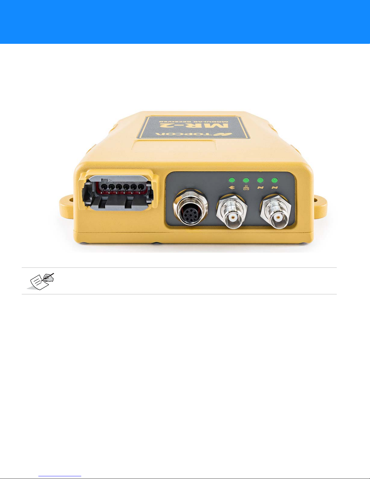
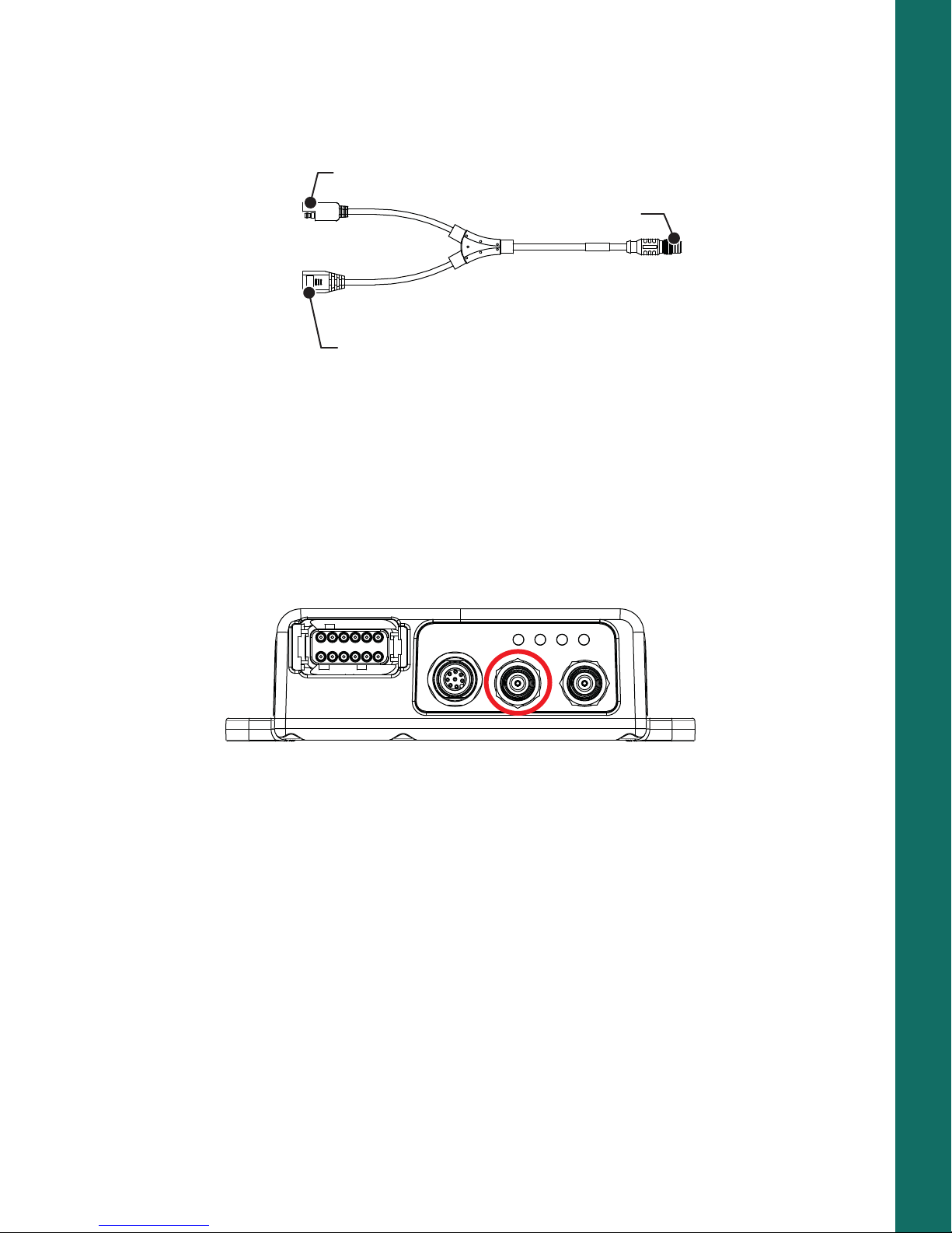
Antenna Connectors
Serial
(Power)
Ethernet
(Power)
Primary
Antenna
Secondary
Antenna
Power
Ethernet STAT
Primary
Antenna
STAT
Secondary
Antenna
Figure 2 shows the antenna connectors for the MR-2. The primary antenna connector is used to connect a GNSS
antenna for precise RTK positioning. You can connect another GNSS antenna to the secondary connector for
heading and inclination determination. For more information, see
page 14.
For complete MR-2 operation, the external antenna supports at least GPS L1C/A, L2C, L2P (Y), GLONASS L1/L2,
and SBAS (WASS/MSAS/EGNOS) signal tracking and accept voltage at +4.75 to +5.10 VDC at 0-70 mA.
Topcon guarantees performance specifications of the MR-2 only when used with Topcon antennas, such as PGF1 GNSS antennas.
“Step 4: Connect Dual Antennas (HD2)” on
Getting Acquainted
Communication and Power Port
Figure 2: MR-2 Interface
P/N: 1011907-01
5
Page 15

Option Authorization File (OAF)
Topcon Positioning Systems issues an Option Authorization File (OAF) to enable the specific options that
customers purchase. An Option Authorization File allows customers to customize and configure the receiver
according to particular needs, thus only purchasing those options needed.
Typically, all receivers ship with a temporary OAF that allows it to be used for a predetermined period of time.
When the receiver is purchased, a new OAF permanently activates the desired, purchased options. Receiver
options remain intact when clearing the NVRAM or resetting the receiver.
The OAF enables the following kinds of functions:
•
Signal tracking (standard L1 GPS; optional L2, signal tracking)
•
Update rate (standard 1Hz; optional 5, 10, 20, 50, or 100 Hz)
•
RTK at 1, 5, 10, 20, 50, and 100 Hz
•
RTCM/CMR Input/Output
•
2-D attitude determination
•
Advanced multipath reduction
•
Satellite Based Augmentation System positioning (WAAS/EGNOS/MSAS)
•
RS-232C (2x) connectivity
Visit the TPS website (or consult a TPS dealer) for a complete list of available OAF options, details,
and upgrades.
Getting Acquainted
Twin Antenna System (HD2)
The MR-2 receiver includes a twin antenna system called HD2. It derives 2D attitude parameters, namely the
heading and inclination, of the baseline between two antennas mounted on a platform. For more information,
see “Twin Antenna System for Heading and Inclination Determination (HD2)” of the
B125 Integrator’s Guide
.
Option Authorization File (OAF)
P/N: 1011907-01
6
Page 16

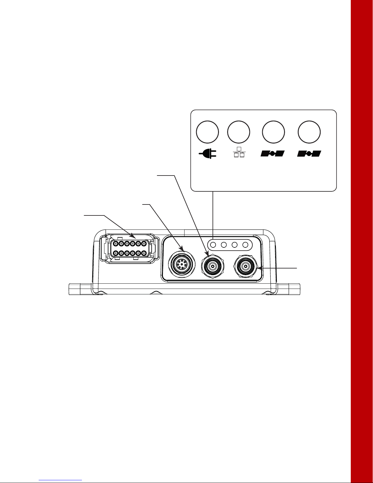
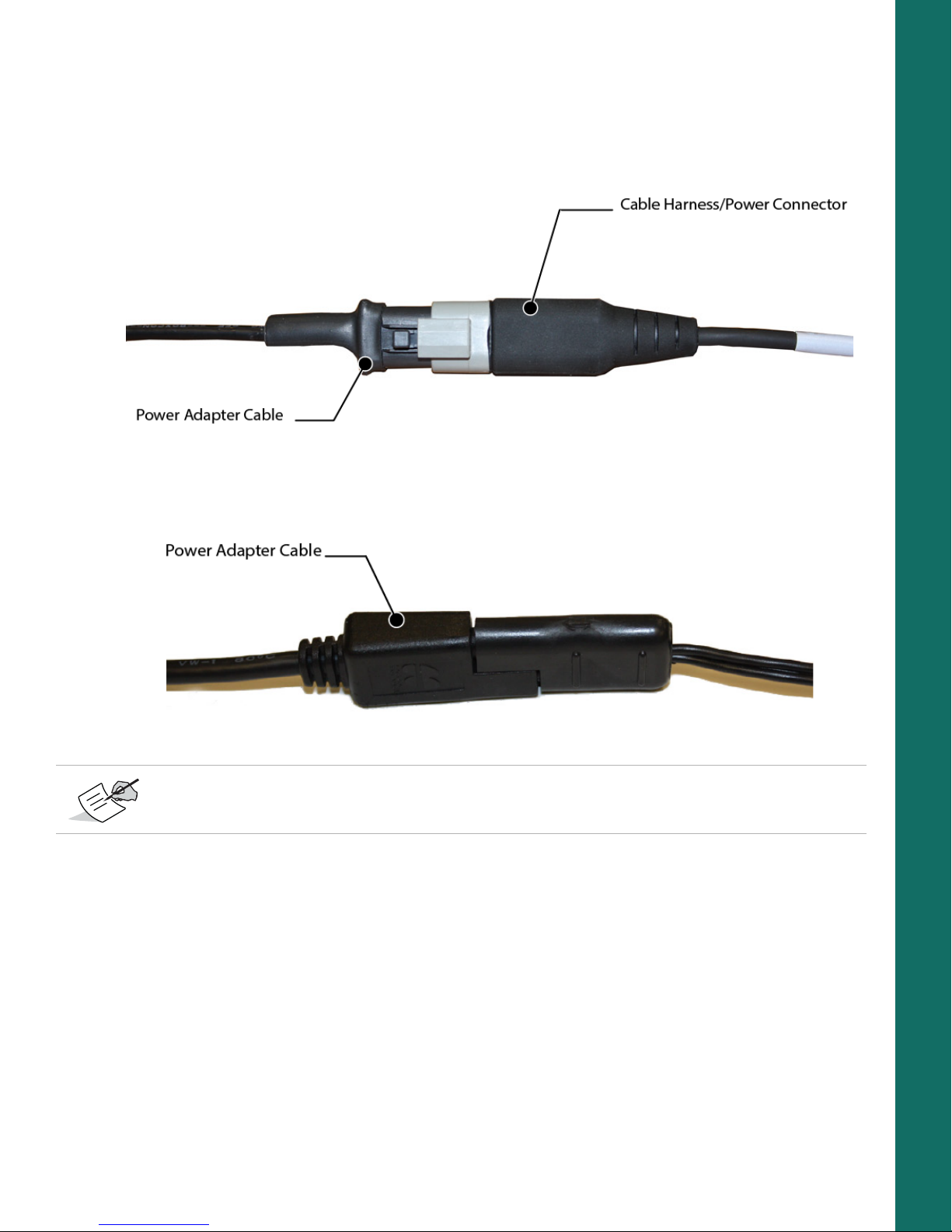
Cables and Accessories
Standard Cables
The MR-2 package includes a cable harness that breaks out two serial communication ports and a power supply
connection to the receiver.
Cable Description Cable Illustration
Cable Harness
• Deutsch 3-pin connector: Connects the
receiver to a 9-36 VDC power supply.
• DB-9 connectors: Connects the receiver to
external devices (controller or computer)
for data transfer and receiver
configuration.
• BNC connector: Provides accurate time
transfer to external devices.
p/n: 14-008207-02LF
Power Adapter
Converts the Deutsch 3-pin connector to an
SAE connector for connection to a 9-36 VDC
power supply.
p/n 1000231-01
Table 1 lists these cables.
Getting Acquainted
Table 1. MR-2 Package Cables
Ethernet Cable
• SAE connector: Connects the receiver to a
9-36 VDC power supply.
• Ethernet connector: Connects the receiver
to external devices (controller or
computer) for data transfer and receiver
configuration.
• M12 connector: Connects to the M12
connector on the receiver.
p/n: 1008816-01
Cables and Accessories
P/N: 1011907-01
7
Page 17
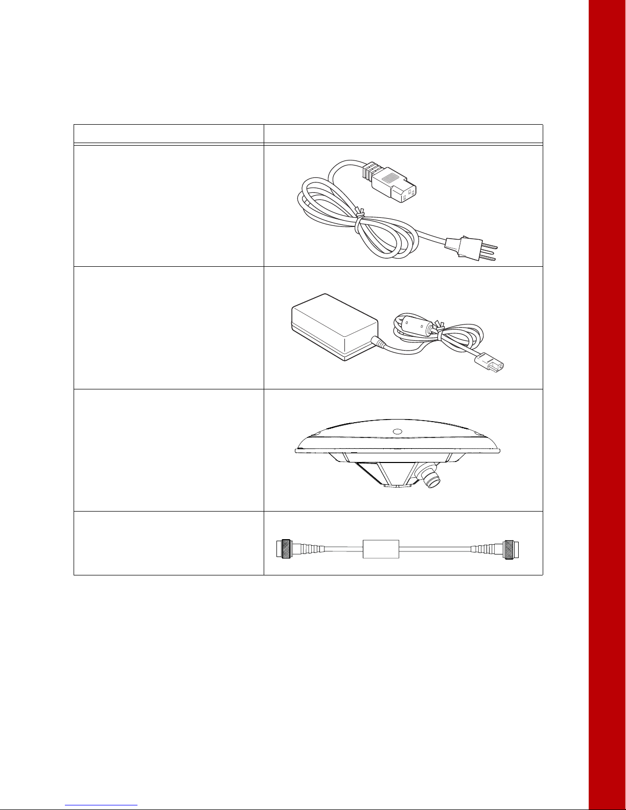
Receiver Accessories
The MR-2 has a variety of accessories to increase its ease of use and facilitate installation. Ta bl e 2 lists these
accessories. For more details on the optional accessories available for the MR-2, contact a local Topcon dealer.
Table 2. MR-2 Package Cables
Cable Description Cable Illustration
Cable, Power/Charger
Connects the power supply unit to a
grounded outlet.
p/n 14-008052-01 (US)
p/n 14-008053-01 (AUS)
p/n 14-008054-01 (EUR)
Power Supply Unit
Converts the alternating current (AC)
supplied from an electrical outlet to a direct
current (DC) for powering the receiver.
The unit connects to the receiver via the
power adapter cable.
p/n 22-034101-01
Getting Acquainted
Full Wave Antenna
For optimal performance, the MR-2 should be
paired with a high precision Topcon GNSS
antenna. The PG-F1 offers high performance
signal tracking for full constellation operation,
while the PG-S1 may be used for dual
frequency configurations.
Cable, External Antenna
Connects the external antenna to the
receiver.
Cables and Accessories
P/N: 1011907-01
8
Page 18

Mounting the Receiver
29
(1.14)
80
(3.15)
153.7
(6.05)
165.9
(6.53)
128.8
(5.07)
11.7
(0.46)
152
(5.98)
163.1
(6.42)
136.4
(5.37)
7 Dia.
(.28)
4 PLCS
8.5
(0.33)
48.5
(1.91)
134.4
(5.29)
136.4
(5.37)
171.7
(6.76)
The four mounting flanges on the MR-2 housing enable you to easily secure the receiver in any orientation, onto
any hard surface, with the strength to withstand tough environmental conditions (
Getting Acquainted
Figure 3).
Figure 3: MR-2 Mounting Dimensions
Mounting the Receiver
P/N: 1011907-01
9
Page 19
• • • • • •
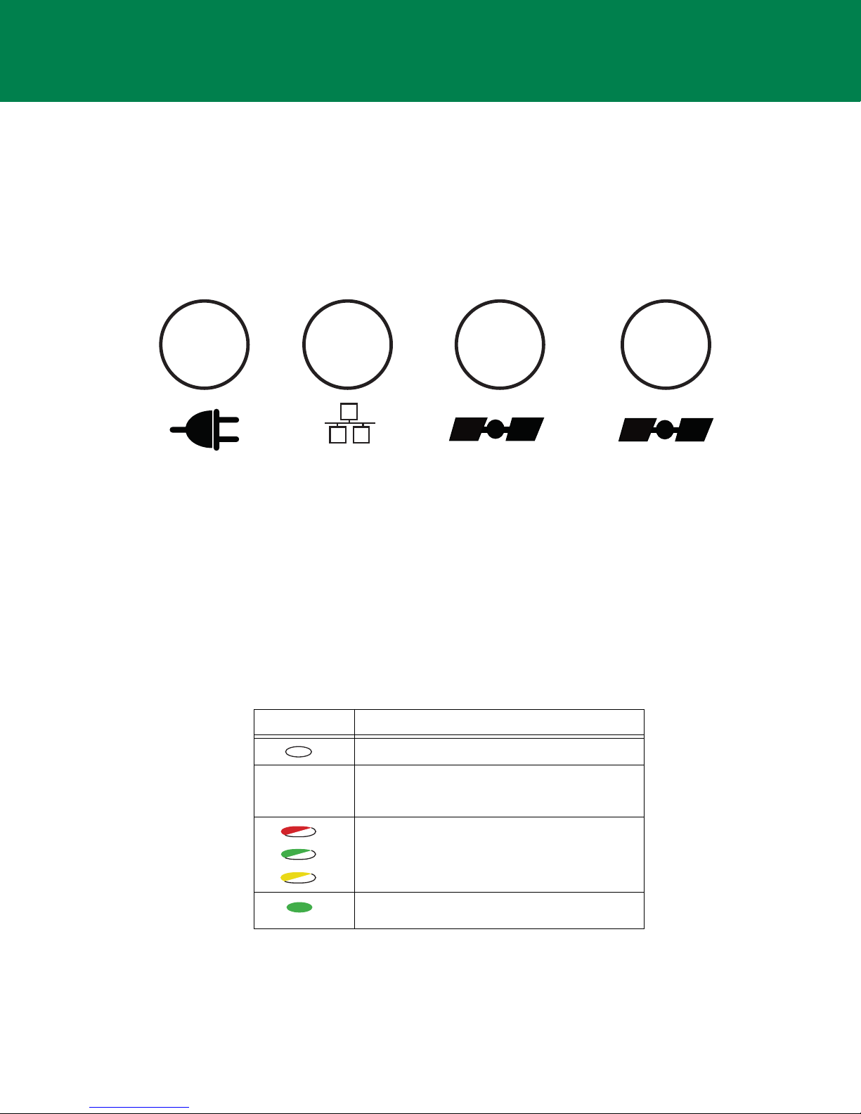
LED Indicators
Power Ethernet
STAT
(Primary Antenna)
STAT
(Secondary Antenna)
The LED indicators able you to control receiver power and data recording. The LEDs display the status of the
power, Ethernet connectivity, and satellite tracking. This chapter describes the different LED blink patterns and
what they mean.
Receiver Status LEDs
There are four status LEDs to provide you information about power Ethernet connectivity, and tracked satellites.
This section describes the color and behavior of each LED.
Power LED
The Power LED indicates whether the receiver is on or off, and to indicate the status and type of OAF loaded.
Figure 4: LED Indicators
Table 3. Power LED Patterns
LED Color Description
When the LED is off, the receiver is off.
When the LED is blinking or solid, the receiver is
on and an OAF is loaded. See below for the types
of OAF.
When the LED continuously blinks between red,
green and yellow, a standalone positioning OAF is
loaded.
When the LED is solid green, an RTK-enabled OAF
is loaded.
LED Indicators
P/N: 1011907-01
10
Page 20

Ethernet LED
The Ethernet LED indicates the status of the Ethernet connection.
Table 4. Ethernet LED Patterns
Display Description
Solid Red: No Ethernet connection.
Solid Green: Ethernet Connection
established.
Satellite Tracking (STAT) LED
There are two LEDs to indicate the status of satellite tracking. If your receiver has only one B125 board, only
the STAT LED for the primary antenna will operate (
board will both STAT LEDs operate. The number of blinks the LED makes indicates the number of satellites for
that constellation.
Blink Order Definition
1 Green blink per tracked GPS satellite
Table 5 describes the blink patterns.
Table 5. STAT LED
Figure 4 on page 10). If your receiver has a second B125
LED Indicators
2 Dark once
3 Yellow blink per tracked GLONASS satellite
4 Dark once
5 Cyan blink per tracked Galileo satellite
6 Dark once
7 Magenta blink per tracked Compass satellite
8 Dark once
9 Blue blink for each QZSS satellite
10 • One red blink: Receiver is not tracking satellites or does
not have a valid position solution
• Dark: Receiver has a valid position solution
Receiver Status LEDs
P/N: 1011907-01
11
Page 21
• • • • • •
System Setup
Before using the MR-2, you will need to connect the necessary cables and antenna(s), and install the Topcon
software, which enables you to configure the receiver. This chapter describes how to set up your new receiver.
Cable and Antenna Connections
The MR-2 receiver is designed to use either a serial cable or Ethernet cable for full operation. The cable and
antenna setup for serial and Ethernet is described below.
Serial Cable Setup
Step 1: Power the Receiver
You can apply power to both ports at the same time. The receiver draws power from the port with the higher
voltage. If both voltages are the same, power will passively switch between both ports. The switching happens
within operating range, and causes no drop in power. The receiver will work without interruption.
1. Mount the receiver to a suitable hard surface where the LED is visible and the ports are accessible. See also
“Mounting the Receiver” on page 9.
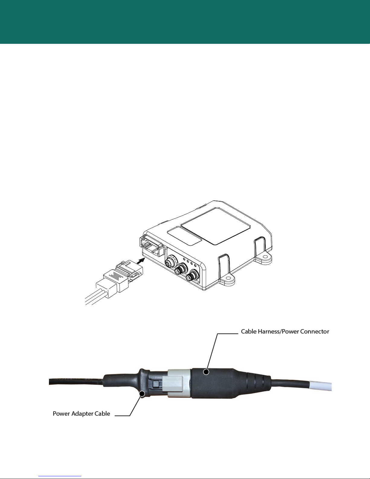
2. Connect the supplied serial cable harness to the power/communication port (Figure 5).
Figure 5: Connecting the Serial Cable Harness to the Receiver
3. Connect the adapter cable to the power connector of the cable harness, as shown in Figure 6.
Figure 6: Power Adapter Cable to the Power Connector
System Setup
P/N: 1011907-01
12
Page 22
4. Connect the other end (SAE connector) of the power adapter cable to a 9-36 VDC power supply unit with
an SAE connector, as shown in
Figure 7: Power Adapter Cable to Power Supply Unit
Figure 7.
You can also create a custom cable to connect a 9-36 VDC directly to the 3-pin Deutsch connector on
the break-out harness.
5. Verify the power supply is on and supplying power.
6. Make sure the MR-2 LED is lit solid, which indicates it is receiving power.
System Setup
Step 2: Connect to a Computer or Display Unit and RTK Correction Source
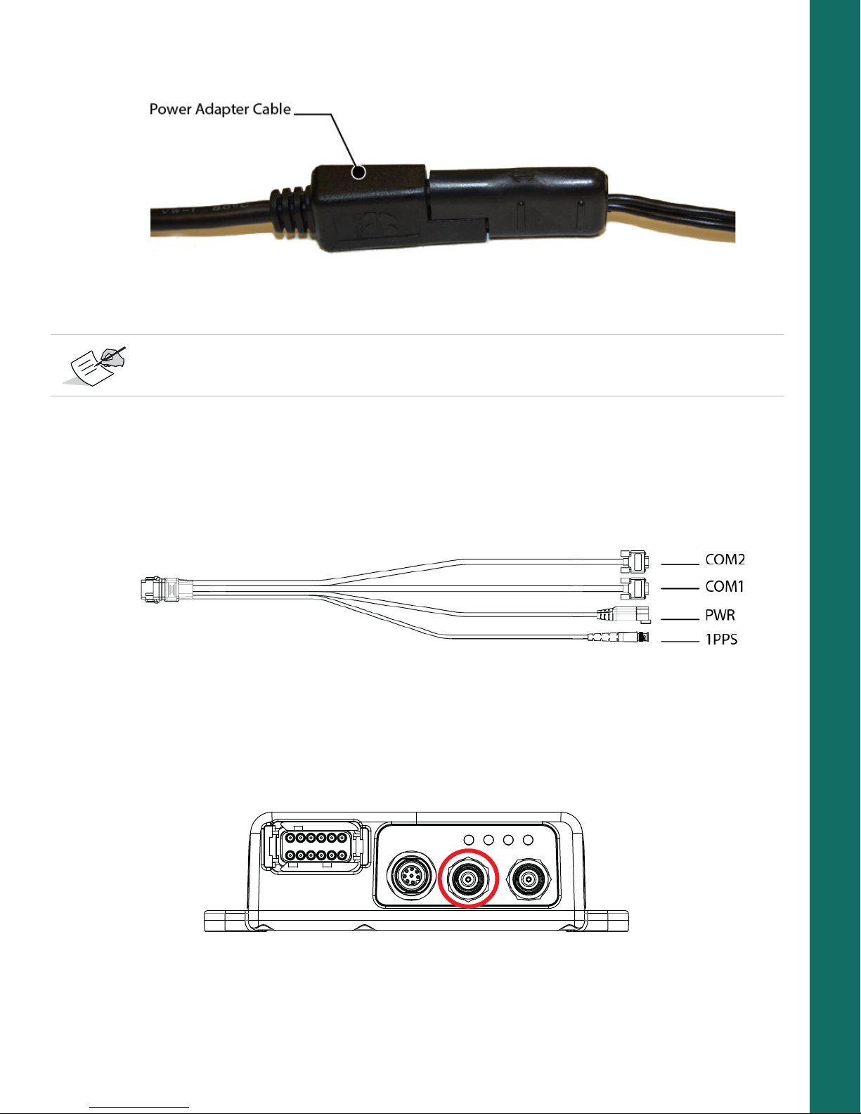
1. Connect the COM1 serial port connector on the cable harness to the serial port on the computer or display.
2. (Optional) If the MR-2 is RTK enabled, connect the COM2 serial port connector to the serial port of the RTK
correction source.
Figure 8: Cable Harness – COM1 and COM2 Serial Ports
Step 3: Connect a Single Antenna
To connect a single external antenna for precise positioning:
1. Mount the GNSS antenna on a rigid surface.
2. Connect the antenna cable to the primary antenna connector circled in red in Figure 9.
3. Make sure the antenna cable is connected to the antenna.
Cable and Antenna Connections
Figure 9: Primary Antenna Connector
P/N: 1011907-01
13
Page 23
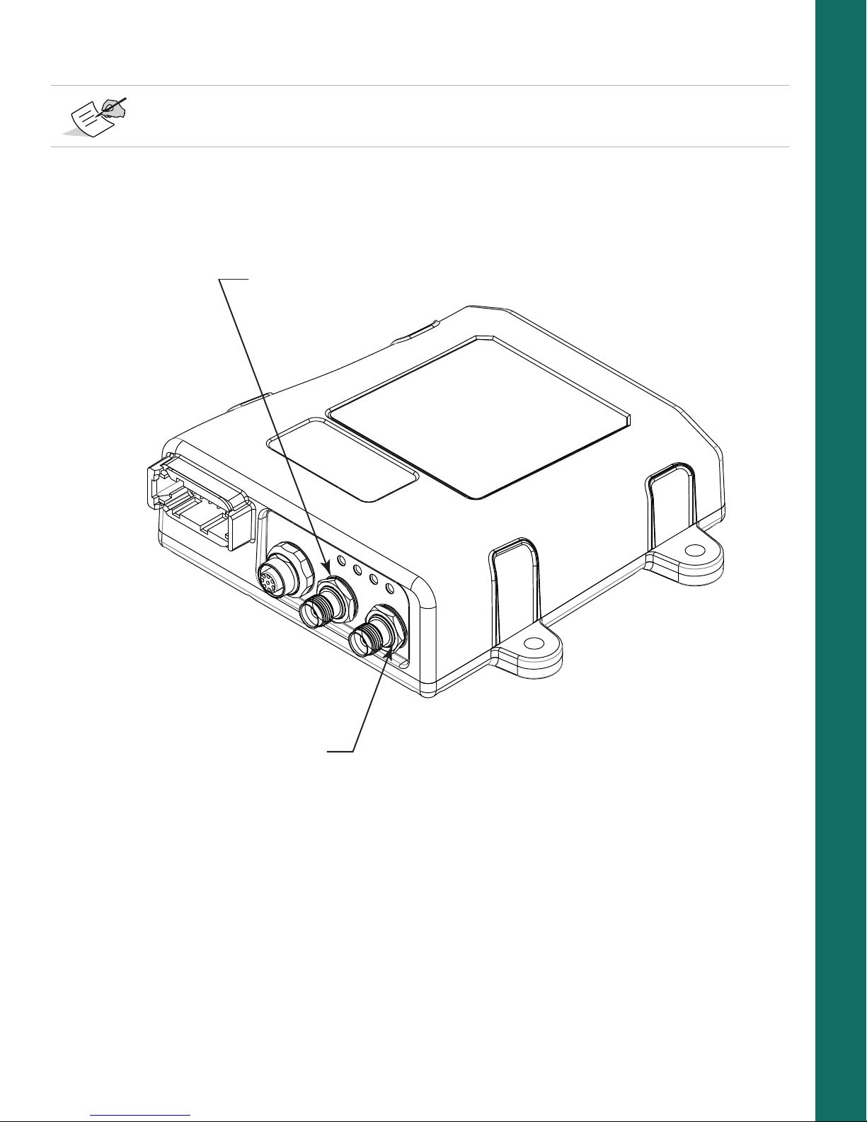
Step 4: Connect Dual Antennas (HD2)
Primary Antenna
Secondary Antenna
HD2 Heading Determination (OCTO) OAF options must be enabled, in addition to a minimum of GPS
L1/L2 signal tracking.
1. Mount both antennas on a rigid platform. The recommended antenna orientation is parallel to the direction
of travel; however, you can use any azimuth.
2. Connect the primary antenna cable to the rear antenna and to the primary antenna connector (Figure 10)
of the MR-2.
System Setup
Figure 10: Antenna Connectors
3. Connect the secondary antenna cable to the front antenna and the secondary antenna connector of the
MR-2.
4. Enable HD2 moving base corrections at the primary antenna, and HD2 heading determination at the
secondary antenna. See the
B125 Integrator’s Guide
for more information.
Step 5: Connect to a PPS Signal
1. Connect the PPS connector on the cable harness to a PPS input port of a suitable instrument.
2. Configure the PPS output with GRIL commands. To do this, see the
B125 Integrator’s Guide
.
Cable and Antenna Connections
P/N: 1011907-01
14
Page 24
Ethernet Cable Setup
Step 1: Power the Receiver
1. Mount the receiver to a suitable hard surface where the LED is visible and the ports are accessible
(see “Mounting the Receiver” on page 9).
2. Connect the adapter cable to the power connector of the cable harness, as shown in Figure 11.
Figure 11: Power Adapter Cable to the Power Connector
3. Connect the other end (SAE connector) of the power adapter cable to a 9-36 VDC power supply unit with
an SAE connector, as shown in
Figure 12.
System Setup
Figure 12: Power Adapter Cable to Power Supply Unit
You can also create a custom cable to connect a 9-36 VDC directly to the 3-pin Deutsch connector on
the break-out harness.
4. Verify the power supply is on and supplying power.
5. Make sure the MR-2 LED is lit solid, which indicates it is receiving power.
Cable and Antenna Connections
P/N: 1011907-01
15
Page 25
Step 2: Connect the Ethernet Cable
Connect to MR-2
Connect to Source
Connect to Power
The MR-2 allows up to five virtual TCP port connections using the same IP address. Virtual TCP ports can be
used to connect the device to a PC (for control) and to an RTK source.
Ethernet cable.
Figure 13: Ethernet Cable Connections
1. Connect the Ethernet cable to the MR-2.
2. Connect the RJ45 end of the Ethernet cable to a source.
3. Connect the SAE end of the Ethernet cable to a power source.
Figure 13 shows the connections for the
Step 3: Connect a Single Antenna
System Setup
To connect a single external antenna for precise positioning:
1. Mount the GNSS antenna on a rigid surface.
2. Connect the antenna cable to the primary antenna connector circled in red in Figure 14.
Figure 14: Primary Antenna Connector
3. Make sure the antenna cable is connected to the antenna.
Cable and Antenna Connections
P/N: 1011907-01
16
Page 26

Step 4: Connect Dual Antennas (HD2)
Primary Antenna
Secondary Antenna
HD2 Heading Determination (OCTO) OAF options must be enabled, in addition to a minimum of GPS
L1/L2 signal tracking.
1. Mount both antennas on a rigid platform. The recommended antenna orientation is parallel to the direction
of travel; however, you can use any azimuth.
2. Connect the primary antenna cable to the rear antenna and to the primary antenna connector (Figure 15)
of the MR-2.
System Setup
Figure 15: Antenna Connectors
3. Connect the secondary antenna cable to the front antenna and the secondary antenna connector of the
MR-2.
4. Enable HD2 moving base corrections at the primary antenna, and HD2 heading determination at the
secondary antenna. See the
B125 Integrator’s Guide
for more information.
Step 5: Connect to a PPS Signal
1. Connect the PPS connector on the cable harness to a PPS input port of a suitable instrument.
2. Configure the PPS output with GRIL commands. To do this, see the
B125 Integrator’s Guide
.
Cable and Antenna Connections
P/N: 1011907-01
17
Page 27

Install the Topcon Receiver Utility (TRU)
TRU is Topcon’s GNSS receiver configuration software. You can download the software from Topcon’s myTopcon
Website (https://www.topconpositioning.com/support). For more information on any of the procedures in this
section or on TRU, refer to the
Computer requirements for TRU are: Microsoft® Windows XP/Vista/7 operating system, an RS-232C port, or an
Ethernet port. Mobile editions are also available for Topcon supported devices equipped with serial connections
running WinCE 5, WinCE 6, WinMobile 6.1/6.5/6.5.3.
To install and run TRU on a computer:
1. Visit myTopcon (https://www.topconpositioning.com/support) and download the file.
2. Locate the TRU.exe file on your computer, and double-click the file to run the installation wizard.
3. Following the on-screen instructions. After installing, a TRU shortcut appears on your desktop.
4. To start TRU, double-click the shortcut, or select it from the Start menu. The TRU main screen appears
(
Figure 16).
TRU Online Help
embedded in the software.
System Setup
Install the Topcon Receiver Utility (TRU)
Figure 16: TRU – Main Screen
P/N: 1011907-01
18
Page 28

• • • • • •
Managing Power
This chapter describes how to power the receiver and use an external power source.
Turning the Receiver On/Off
Use a 5A fuse if connecting directly to a vehicle DC power source.
1. To turn on the receiver, connect either a serial or Ethernet cable from the unit to a power source.
2. To turn off the receiver, disconnect either the serial or Ethernet cable from the unit.
Once the cable is disconnected, the receiver will begin an internal shutdown process lasting approximately 1 to
1.5 minutes. During this process, the receiver is not receiving power, but the power LED remains on until the
end of the shutdown process.
After shutdown, the receiver will begin the startup process lasting approximately 1 to 1.5 minutes. Some
receiver functions may be available during this process. All functions of the receiver are available when the
startup process completes.
Powering the Receiver
The receiver is powered by an external power source connected to either the serial connector or Ethernet
connector.
Power input greater than 36 VDC could damage the receiver.
Connect to an External Power Source
To power the receiver with an external power supply, connect the SAE connector to a power supply operating
between 9 and 36 volts.
Power Cycling
If power is removed from the receiver, it will take up to two minutes for a complete shutdown. When the receiver
is powered on, it will take approximately one minute for a full reboot.
Managing Power
P/N: 1011907-01
19
Page 29

• • • • • •
Configuration
Configuring the receiver enables you to change GPS settings, verify satellite tracking, etc. To do this, you’ll need
to use the Topcon Receiver Utility (TRU) software available the myTopcon Website
(https://www.topconpositioning.com/support). See
more information.
The sections in this chapter describe how to use TRU to configure the receiver. Once this is accomplished, you can:
•
Set up GPS parameters and other settings
•
Monitor the receiver’s GPS status
•
Log raw data to a file
•
Load a new OAF, firmware, and other configuration files to the receiver
Connect The Receiver to TRU
The steps in this section work with receivers that have one or two boards.
1. Connect the receiver and computer as described in “Step 2: Connect to a Computer or Display Unit and RTK
Correction Source” on page 13.
2. Start TRU on the computer. The TRU main screen displays (Figure 17). Initially the tools are inactive.
“Install the Topcon Receiver Utility (TRU)” on page 18 for
3. Click DeviceApplication ModeReceiver Managing.
4. Click DeviceConnect. The Connection Parameters screen appears.
Configuration
Figure 17: TRU – Main Screen
P/N: 1011907-01
20
Page 30

5. Select Serial Port for the Connect Using drop-down list (Figure 18).
Configuration
Figure 18: TRU – Connection Parameters
6. Click the Browse button to the right of
7.
Choose a port from the
Select Port
screen, and click OK (Figure 19). The
appears.
Port Name
.
Connection Parameters
screen
The Port Name shows the friendly and physical name of the computer port. The application remembers the
last used transport, and the last used successful port/device name for every transport, making it easy to connect
to the same device.
Connect The Receiver to TRU
Figure 19: TRU – Select Port Screen
P/N: 1011907-01
21
Page 31

8. If using a secondary receiver board, select the Secondary Receiver check box, and select Serial C from
the Receiver Port drop-down list (
9. Click Connect to establish a connection.
Once the receiver connects to TRU, the icons on the main screen become active. Once active, you can configure
the receiver.
Ethernet Connection
This section describes how to customize the Ethernet settings in the receiver, and how to connect to the receiver
with TRU using an Ethernet connection.
Receiver Ethernet Settings
To verify Ethernet connectivity, the receiver must be connected to an external network or laptop. For a laptop
connection, set up a static IP address on the computer.
Once connected, the Ethernet LED will be solid 2-5 seconds after the receiver is powered on, indicating that an
Ethernet connection is established. If the Ethernet LED does not become green after 10 seconds, check the
external network connect, or reboot the receiver.
View Receiver IP Addresses
The receiver contains a main and auxiliary GNSS board. The IP address for the main board is 192.168.0.9 and
the IP address for the auxiliary board is 192.168.0.10.
To view the IP address of each board, do the following.
1. Connect the receiver to TRU using a Serial connection. See “Connect The Receiver to TRU” on page 20.
2. In TRU, click Receiver SettingsNetwork. The Network screen appears and the Ethernet tab is
active (
Figure 20).
Configuration
Figure 18 on page 21).
3. Write down the IP Address and Gateway.
Ethernet Connection
Figure 20: TRU – Network Screen
P/N: 1011907-01
22
Page 32

Set Up a Static IP Address For the Laptop
When setting up the static IP address of the laptop, the first three numbers of the IP address must match the
receiver’s IP address. For example, if the receiver’s IP address is 10.5.57.200, the computer IP address must be
10.5.57.xxx.
1. Open the Network and Sharing Center on your laptop.
2. Change your Local Area Connection TCP/IPv4 settings to match the receiver (Figure 21).
Configuration
Figure 21: Laptop Internet Protocol Settings
3. Enter the IP address for the primary board (see “View Receiver IP Addresses” on page 22).
4. If needed, enter the Default gateway address.
5. Click OK to apply the changes to your laptop.
Ethernet Connection
P/N: 1011907-01
23
Page 33

View Receiver Password
1. Connect the receiver to TRU using a Serial connection (see “Connect The Receiver to TRU” on page 20).
2. Click Receiver SettingsNetwork. The Network screen appears (Figure 22).
Configuration
Figure 22: Network – TCP Tab
3. Click the TCP tab. The password displays in the Password field.
Change Password
1. Connect the receiver to TRU using a Serial connection (see “Connect The Receiver to TRU” on page 20).
2. Click Receiver SettingsNetwork. The Network screen appears (Figure 22).
3. Click the TCP tab, and enter a new password in the Password field.
4. Click OK, and reset the receiver to enable the new password.
For all receivers, the default password is
topcon
.
Reset the Receiver
After changing Ethernet settings, reset the receiver. Open the Terminal window, enter
Send. The IP addresses become assigned within 30 seconds after reset. The Receiver will reply with a ping,
and become accessible by TCP ports from TRU or PC-CDU. Click X to close Terminal and go to the TRU main
screen.
Shutdown of the receiver takes approximately 1 to 1.5 minutes. After shutdown, the receiver takes
approximately 1 to 1.5 minutes to restart. After restart, all functions of the receiver are available.
set,reset,yes
and click
Ethernet Connection
P/N: 1011907-01
24
Page 34

Connect to TRU Using Ethernet
1. Start TRU on the computer. The TRU main screen displays (Figure 17 on page 20). Initially the tools are
inactive.
2. Click DeviceApplication ModeReceiver Managing.
3. Click DeviceConnect. The Connection Parameters screen appears.
4. Select Network from the Connect Using drop-down list (Figure 23).
Configuration
Figure 23: TRU Connection Parameters – Network
Ethernet Connection
P/N: 1011907-01
25
Page 35

5. If needed, click the Browse icon to the right of
Devices
screen, and click OK (Figure 24). The
Connection Parameters
Port Name
to choose a port from the
screen appears.
My Network
Configuration
Figure 24: My Network Devices – Ethernet Device
The Port Name shows the friendly and physical names of the computer port. The application remembers the
last used transport, and the last used successful port/device name for every transport, making it easy to connect
to the same device.
6. If needed, right-click on the desired port and click Edit. The Network Connection Parameters screen
appears (
Figure 25).
Figure 25: Network Connection Parameters
7. Enter the IP address and password of the GNSS receiver you want to connect to. The main board IP
address is
8. Enter
192.168.0.9
8002
as the default for TCP Port, and click OK. The Connection Parameters screen appears.
, and the auxiliary board IP address is
9. Click Connect to connect to the receiver.
Ethernet Connection
P/N: 1011907-01
192.168.0.10
.
26
Page 36

Configure the Receiver
The following base and rover configurations are recommended for the most common applications; however, you
can select configuration parameters as needed.
Configuration
Do not make other changes without consulting the
TRU Online Help
, embedded in the software.
Configure the Receiver as a Base
The following describes how to configure the receiver as a base.
Configure the Antenna
1. In TRU, click DeviceApplication ModeReceiver ManagingReceiver Settings. The Receiver
Settings screen appears (
Figure 26).
2. Click Tracking & Positioning. The Tracking & Positioning screen appears (Figure 27 on page 28).
3. Click the Antenna tab, and set the GNSS Antenna type to External.
Configure the Receiver
Figure 26: TRU – Receiver Settings
P/N: 1011907-01
27
Page 37

Configuration
Figure 27: Set Antenna Usage
4. Click the Obs tab, and set the following parameters (Figure 28):
•
Elevation Mask, deg
•
Elevation Mask, deg
•
PDOP Mask
: Set
: Set
Satellites Tracking
: Set
Position Computation
Position Computation
to 5 degrees.
to 13 degrees.
to 30 degrees.
Figure 28: Configure Receiver Positioning – Elevation Mask
Configure the Receiver
P/N: 1011907-01
28
Page 38

5. Click the Adv tab, and set the following parameters (Figure 29):
•
Select the C/A code multipath reduction check box. This reduces the C/A code phase multipath.
•
Select the C/A carrier phase multipath reduction check box. This reduces the C/A carrier phase multipath.
•
Ensure that the Cinderella check box is unselected. Only select this option if you want to set all of the receiver
options to their maximum allowable values for 24 hours every other Tuesday at GPS midnight.
Configuration
Figure 29: Configure Advanced Parameters
6. Click OK to return to the Receiver Settings screen.
7. Configure the reference coordinates by entering them using GRIL commands (see “Commands” of the
GRIL Reference Guide
You can also set the reference coordinates using the Base tab in TRU (Figure 30).
).
Figure 30: Set Reference Coordinates in the Base Tab
Configure the Receiver
P/N: 1011907-01
29
Page 39

Set Up the Receiver Serial Ports
1. In TRU, click DeviceApplication ModeReceiver ManagingReceiver Settings. The Receiver
Settings screen appears (
Figure 31).
Configuration
Figure 31: TRU – Receiver Settings
2. Click Ports. The Receiver Ports screen appears (Figure 32 on page 30).
3. Double-click the appropriate Serial Port name (Figure 33 on page 31). The Settings screen for that port
appears.
4. In the Settings screen, select the following (Figure 33):
•
Input Mode
•
Output Mode
Configure the Receiver
– Select
– Select
Command
RTK RTCM 3.1
Figure 32: TRU – Receiver Ports
P/N: 1011907-01
30
Page 40

Configuration
Figure 33: TRU – Serial Port Settings
5. Click OK to return to the Receiver Ports screen.
If you want to set up additional messages, follow the process below. Otherwise click X to return to the Receiver
Settings screen, then click Back to return to the TRU main screen.
Set Up The Receiver TCP Port
1. In TRU, click DeviceApplication ModeReceiver ManagingReceiver Settings. The Receiver
Settings screen appears (
Figure 34).
2. Click Ports, then click the TCP tab. The Receiver Ports screen for the TCP tab appears (Figure 35).
3. Double-click the appropriate TCP Port name (Figure 35). The Settings screen for that port appears.
Configure the Receiver
Figure 34: TRU – Receiver Settings
P/N: 1011907-01
31
Page 41

Figure 35: TRU – Receiver TCP Port
Configuration
4. In the Settings screen, select the following (Figure 36):
•
Input Mode
•
Output Mode
– Select
– Select
Command
RTK RTCM 3.1
Configure the Receiver
Figure 36: TRU – TCP Port Settings
P/N: 1011907-01
32
Page 42

5. Click OK to return to the Receiver Ports screen.
Disabling authentication or changing the port number is done in the TCP tab.
6. If you want to set up additional messages, follow the process below. Otherwise click X to return to the
Receiver Settings screen, then click Back to return to the TRU main screen.
Set Up Additional Messages (Optional)
1. In the Settings screen for your selected serial port, click Messages. The Messages screen appears
(
Figure 37 on page 33).
Configuration
2. Right-click in the screen and click Add new messages. The Receiver Message List screen appears
(
Figure 38 on page 34).
Configure the Receiver
Figure 37: TRU – Serial Port Messages
P/N: 1011907-01
33
Page 43

Configuration
Figure 38: Add New Serial Port Messages
3. Click the (+) icon to expand the rtcm3 list, and select a message you want to add (Figure 39).
4. Double-click the message to add it. The message appears in the bottom list panel. (Figure 39).
Figure 39: New Serial Port Message Added
If you want to edit the new message, follow the procedure below. Otherwise, Click OK to return to the Settings
screen. Click OK again to return to the Receiver Ports screen, and Click X to return to the Receiver Settings
screen. Finally, click Back to return to the TRU main screen.
Configure the Receiver
P/N: 1011907-01
34
Page 44

Edit Additional Messages (Optional)
1. Right-click on the new message from the bottom list panel of the Receiver Message List screen.
2. Click Edit message. The Receiver Message screen appears (Figure 40).
Configuration
Figure 40: Edit a New Message
3. Edit the information as needed, and click OK. The Receiver Message List screen appears.
4. Click OK to return to the Messages screen, then click OK again to return to the Settings screen.
5. In the Settings screen, click OK to return to the Receiver Ports screen, then click X to return to the
Receiver Settings screen.
6. Click Back to return to the TRU main screen.
Configure the Receiver as a Rover
The following describes how to configure the receiver as a rover.
Set the Receiver Positioning
1. Follow steps 1-6 in “Configure the Antenna” on page 27.
2. In the Receiver Settings screen, click Tracking & Positioning. The Tracking & Positioning screen
appears
3. Click the Positioning tab (Figure 41 on page 36).
Configure the Receiver
P/N: 1011907-01
35
Page 45

Configuration
Figure 41: Receiver Settings – Positioning
4. Set the following parameters then click OK to return to the Receiver Settings screen.
•
Positioning Mode
•
Enable Solutions
– Standalone – Where the receiver computes 3D coordinates in autonomous mode without using
differential correction.
– Code Differential – Where the rover receiver computes the current relative coordinate in differential
mode using only pseudo ranges.
– RTK Float – Where the Rover receiver computes the current relative coordinates in differential mode
using both pseudo ranges and phases; however, with a float solution, the phase ambiguity is not a
fixed integer number and the “float” estimate is used instead.
– RTK Fixed – Where the rover receiver computes current relative coordinates, with ambiguity fixing, in
differential mode.
•
DION
– Select the mode in which the DION engine will operate.
– Off – The DION engine is disabled.
– Local – The DION engine provides precise positioning with respect to a starting point.
– Smooth – The DION engine provides smoothed estimates of absolute positions using refined delta
positions from carrier phase processing.
5. Click OK to return to the Receiver Settings screen.
– Select a positioning mode for the receiver.
– Select solutions used in position computation.
Configure the Receiver
P/N: 1011907-01
36
Page 46

Set Up the Receiver Serial Ports
1. In the Receiver Settings screen, click Ports (Figure 42). The Receiver Ports screen appears.
Configuration
Figure 42: Receiver Settings
2. Double-click the appropriate Serial Port name (Figure 42). The Settings screen for that port appears.
3. In the Settings screen, select the following (Figure 43):
•
Input Mode
•
Output Mode
– Select
–
None
RTCM 3.x
4. Click OK to return to the Receiver Ports screen, then click X to return to the Receiver Settings screen.
5. Click Back to return to the TRU main screen.
Configure the Receiver
Figure 43: Serial Port Settings
P/N: 1011907-01
37
Page 47

Set Up The Receiver TCP Port
1. In the Receiver Settings screen, click Ports then click the TCP tab (Figure 44). The Receiver Ports
screen for the TCP tab appears.
Configuration
Figure 44: Receiver Settings
2. Double-click the appropriate TCP Port name (Figure 45). The Settings screen for that port appears.
3. In the Settings screen, select the following (Figure 45):
•
Input Mode
•
Output Mode
– Select
–
None
RTCM 3.x
Configure the Receiver
Figure 45: Serial Port Settings
P/N: 1011907-01
38
Page 48

4. Click OK to return to the Receiver Ports screen, then click X to return to the Receiver Settings screen.
5. Click Back to return to the TRU main screen.
Once the receiver is configured, the configuration remains until changed using TRU or by clearing the NVRAM.
For more details on the settings available for configuring receivers, see the
TRU Online Help
embedded in the
software.
Verify Receipt of Differential Corrections (RTK Rover Only)
1. For RTK Rover receivers, click Status (Figure 46) to ensure the receiver obtains differential correction. The
Status screen appears.
Configuration
Figure 46: TRU – Main Screen and Status Screen
Configure the Receiver
P/N: 1011907-01
39
Page 49

The Data Link tab reflects the status of the received differential messages. If the port is not configured or if
the corrections are not being received, the Link Quality field will be empty.
Configuration
Figure 47: Status – Data Link
2. When finished, click X to close the Status screen and return to the TRU main screen.
3. Click DeviceDisconnect, then DeviceExit to close TRU.
Disconnecting before exiting TRU ensures proper port management.
Configure the Receiver
P/N: 1011907-01
40
Page 50

Configure Receiver for HD2 Operation
HD2 Overview
HD2 Heading Determination (OCTO) OAF options must be enabled, in addition to a minimum of GPS
L1/L2 signal tracking.
The MR-2 can process accurate and instantaneous attitude parameters. The MR-2 combines a pair of B125
receiver boards, and two external antennas, to create a 2D system for heading and pitch. With this method,
one board acts as a moving base, and the other as a rover. The antennas are fixed, and the inter-antenna
distance is constant. The moving base sends standalone position and raw data to the rover, which processes
the data and sends them using ASCII or binary messages.
You can also configure the moving base to accept RTK measurements from a stationary base station. With this
method, the moving base is used as a base and a rover simultaneously. The moving base will process its
position, with centimeter level accuracy, using the measurements from the stationary base station. It will then
transmit the position to the rover.
HD2 operation requires scripts that will configure the receiver by sending commands to the master board of the
MR-2. Several scripts are available on the Topcon Positioning Systems website, which cover the popular work
flows of the MR-2, and can be modified for custom applications.
Configuration
1. Go to
https://www.topconpositioning.com/support/products/mr-2
Firmware & Software Updates (Figure 48).
, and click
2. Connect the primary receiver board to TRU. For more information about connecting to the receiver using
TRU, see
3. Under Software, locate the scripts, click the Download icon, and save the scripts to your computer.
Configure the Receiver
“Connect The Receiver to TRU” on page 20.
Figure 48: MR-2 Product Page
P/N: 1011907-01
41
Page 51

4. Access the Terminal window, and send the script file to the master board by selecting the Send File
menu item.
Scripts are subject to change as firmware matures.
5. To access the heading determination output, connect to the secondary board in TRU, and access the
Status Heading screen. Alternatively, the VHD log can be output from the secondary board.
Check the Receiver’s OAF
Use TRU to view the status of the receiver’s options.
1. Connect the receiver to a computer. See “Step 2: Connect to a Computer or Display Unit and RTK
Correction Source” on page 13
2. Open TRU and connect to the receiver. See “Connect The Receiver to TRU” on page 20.
3. Click the Options icon in the main screen. The Receiver Options screen displays, so you can view
the current authorization options and upload new ones (Figure 49).
Configuration
Check the Receiver’s OAF
Figure 49: Receiver Options
P/N: 1011907-01
42
Page 52

Load an OAF
Each B125 board requires an OAF file provided by Topcon dealers. For any OAF related questions, e-mail Topcon
at options@topcon.com and include the receiver’s ID and serial number. To obtain these numbers, see
the Receiver’s OAF” on page 42.
1. Follow the steps in “Check the Receiver’s OAF” on page 42.
2. Right-click in the Receiver Options screen, and select Upload OAF (Figure 50).
Configuration
“Check
Figure 50: Right-click and Select Upload OAF
3. Navigate to the location of the new Option Authorization File.
4. Select the appropriate file, and click Open (Figure 51).
Load an OAF
Figure 51: Load OAF
P/N: 1011907-01
43
Page 53

Topcon’s TRU initially checks to see if the selected file is compatible with the currently connected receiver. If
you chose a file not intended for this receiver, the Upload OAF window displays an error icon next to the
Receiver ID and disables the Upload the File to the Receiver button.
5. Click Upload the File to the Receiver to start loading the file (Figure 52).
Configuration
Figure 52: Upload the OAF to the Receiver
6. Click Yes at the prompt to reset the receiver (Figure 53).
Figure 53: Reset Receiver
When the receiver resets, the Connection Parameters screen opens.
Load an OAF
P/N: 1011907-01
44
Page 54

7. Click Connect (Figure 54). The TRU main screen appears.
Configuration
Figure 54: Connect to the Receiver
8. Click Options (Figure 55). The Receiver Options screen displays.
Load an OAF
Figure 55: Click Options
P/N: 1011907-01
45
Page 55

9. In the Receiver Options screen (Figure 56), ensure the following are correct:
•
If you upload a universal OAF, make sure the expiration date is still valid.
•
If you upload a customer OAF, make sure the correct customer file is loaded.
Configuration
Figure 56: Receiver Options
10. To view additional OAF details, right-click in the Receiver Options screen and select ViewDetailed
(
Figure 57).
Load an OAF
Figure 57: Additional OAF Details
P/N: 1011907-01
46
Page 56

The Receiver Options screen switches to a detailed view with additional information (Figure 58).
Configuration
Figure 58: Receiver Options – Detailed View
11. Click X to close the Receiver Options screen and return to the TRU main screen.
Load an OAF
P/N: 1011907-01
47
Page 57

Updating Firmware
Updating firmware on the receiver requires an Ethernet connection. If your unit has two B125 boards, each
board requires an update, and each board has a different IP address. The IP address for the main board is
192.168.0.9. The IP address for the auxiliary board is 192.168.0.10. Follow the below procedure for both
boards.
Do not unplug the power or Ethernet connection during the firmware update process.
1. Download the latest firmware build to your PC.
2. Open TRU and click DeviceApplication ModeReceiver Managing.
3. Connect to the receiver using an Ethernet connection (Figure 59).
Configuration
See “Connect to TRU Using Ethernet” on page 25 for more information.
4. Click Connect.
5. Once connected, click DeviceApplication ModeFirmware Loading.
Updating Firmware
Figure 59: TRU – Ethernet Connection
P/N: 1011907-01
48
Page 58

6. Click the Firmware Loading icon. The Select Device screen appears (Figure 60).
Configuration
Figure 60: TRU – Firmware Loading
7. Select Receiver from the Device Type drop-down list.
8. Click Next. The Information screen appears (Figure 61).
9. Verify that the information is correct, and click Next. The Select Files screen appears
(Figure 62 on page 50).
Updating Firmware
Figure 61: TRU – Receiver Information
P/N: 1011907-01
49
Page 59

10. Click the folder icon, navigate to, and select the firmware build you downloaded in step 1.
Configuration
Figure 62: Locate and Select Firmware
11. Click Next to the begin the upload.
Once the begins, a status screen appears (Figure 63). Do not unplug the power or Ethernet connection during
this process.
Updating Firmware
Figure 63: Firmware Upload In Progress
P/N: 1011907-01
50
Page 60

12. When the upload ends, click Finish. A prompt appears indicating that the receiver is updating firmware
(
Figure 64).
Figure 64: Firmware Update In Progress
13. Wait approximately ten minutes for the process to finish.
14. Click OK to return to the Select Device screen.
15. Open the Terminal window in TRU.
16. Enter
During the update process, the receiver will return the following:
print,dev/core:on
and click Send.
RE00F/par/dev/core={
RE01B 0={mode=normal,state=run},
Configuration
RE01F 1={mode=update,state=updateX}}
For
RE01F 1={mode=update,state=updateX}}, X
When the update process is finished, the receiver will return the following:
will increase from 1 to 7.
RE00F/par/dev/core={
RE01B 0={mode=normal,state=run},
RE01B 1={mode=normal,state=run}}
17. Repeat steps 2-16 for the auxiliary board.
18. When both boards have been updates, disconnect from the receiver in TRU.
Updating Firmware
P/N: 1011907-01
51
Page 61

• • • • • •
Use Cases
The MR-2 receiver is suitable for a variety of applications from marine construction to surveying applications. The
MR-2 provides precise positioning, and heading and attitude information. This chapter describes different use
cases for the MR-2 receiver.
GNSS Modular Receiver
The MR-2 is a highly efficient GNSS sensor that you can integrate in various surveying and construction operations
where there are requirements for high accuracy, rapid deployment, and easy integration.
Serial communication available on this modular receiver provides full flexibility to connect to any external radio.
The primary antenna connection enables you to connect an external survey-grade antenna and use the receiver
as a rover suited to the job requirements.
Site Reference Station
You can integrate the MR-2 with an external radio using serial communication, and use it as a base receiver. As a
base, the MR-2 configuration can output RTK corrections in industry standard format for a rover receiver to
produce reliable and accurate RTK positions.
GNSS Sensor for Heading and Attitude
The MR-2 allows for the use of a dual antenna system, called HD2, that derives 2D attitude parameters (heading
and inclination) from the baseline vector between two antennas connected to the MR-2 receiver. Altogether, the
MR-2 can provide the high performance RTK position, heading, and pitch or roll of a vehicle or vessel where it is
deployed.
Use Cases
P/N: 1011907-01
52
Page 62

• • • • • •
Troubleshooting
This chapter will help you diagnose and solve some common problems encountered with the receiver.
Do not attempt to repair equipment yourself. Doing so will void the warranty, and may damage the
hardware.
Check This First
Before contacting Topcon support, check the following:
•
Register your product at https://www.topconpositioning.com/support.
•
Check all external receiver connections carefully to ensure correct and secure connections. Double check for
worn or defective cables.
•
Check the power source for incorrectly connected cables.
•
Check that the most current software is installed onto the computer and that the most current firmware is loaded
into the receiver. Check the TPS website for the latest updates.
Then try the following:
•
Reset the receiver using TRU (
•
Restore default settings using TRU (
If the problem persists, see the following sections for other solutions.
ToolsResent Receiver
ToolsFactory Reset
).
).
Powering Problems
If you are using an external power source, the cable may be disconnected or damaged.
•
Make sure the cable is securely connected and undamaged.
•
Make sure the power source is not defective.
•
Using a volt meter, ensure power is present to the power source output connector.
•
Power cycle the receiver. See “Power Cycling” on page 19 for more information.
Receiver Problems
The following are some of the most commonly encountered receiver problems.
The receiver cannot establish a connection to a computer or external controller.
Cable specific problems:
•
The cable is not properly plugged in:
– Check that the cable connector is attached to the correct receiver port.
– Unplug the cable, then securely and properly reconnect it to the receiver.
•
The cable is damaged:
– Use an undamaged cable. Contact a dealer to replace the cable.
Generic problems:
•
The receiver port used for connection is not in Command mode:
a. Connect the receiver to a computer using a free port (see “Step 2: Connect to a Computer or Display
Unit and RTK Correction Source” on page 13) and start TRU.
b. Open TRU, and connect to the receiver. See “Connect The Receiver to TRU” on page 20.
c. In TRU, click Receiver SettingsPorts.
d. Double-click on the port, and change the Input Mode to Command.
Trou bleshoo ti ng
P/N: 1011907-01
53
Page 63

The receiver does not lock on to satellites for a long period of time.
The corresponding receiver options may be disabled or expired (satellite signals must be enabled with OAFs).
•
Order a new OAF with the desired options activated to enable or extend validity of the corresponding receiver
options. Contact a dealer or visit the TPS website for details.
•
Refer to the
The receiver tracks too few satellites.
The survey is conducted near obstructions (tree canopy, tall buildings, and so forth).
•
Check that the multipath reduction check boxes have been selected.
a. Connect the receiver to a computer using a free port (see “Step 2: Connect to a Computer or
Display Unit and RTK Correction Source” on page 13) and start TRU.
b. Open TRU, and connect to the receiver. See “Connect The Receiver to TRU” on page 20.
c. In TRU, click Receiver SettingsTracking & PositioningAdv tab.
d. Make sure the C/A code multipath reduction check box is selected.
•
Move to an area free of obstructions, if possible.
The receiver cannot obtain Code Differential and/or RTK solutions.
•
Incorrect Base coordinates entered.
– Specify the correct coordinates for the base station using TRU or another suitable field data collection
software.
•
The receiver is not configured as a Base or Rover.
– If the receiver should function as a Base, ensure it has the proper configuration. See “Configure the
Receiver as a Base” on page 27 for details.
– If the receiver should function as a Rover, ensure it has the proper configuration. See “Configure the
Receiver as a Rover” on page 35 for details.
•
The corresponding receiver options may be disabled or expired.
– Order a new OAF with the required options activated to enable or extend validity of the corresponding
receiver options. Contact a dealer or visit the TPS website for details
– Refer to the
•
There are not enough common satellites. In order to obtain a fixed solution, the Base and Rover should track
at least five common satellites.
– Check the elevation masks of the rover and base receivers; they should be the same. To do this, on the
TRU main screen, choose Receiver SettingsTracking & PositioningObs tab.
– Verify there is a clear view of the sky to allow sufficient satellite tracking.
•
A discrepancy exists between the differential standards used at the base and rover receivers.
a. Connect the receiver to a computer using a free port (see “Step 2: Connect to a Computer or
Display Unit and RTK Correction Source” on page 13) and start TRU.
b. Open TRU, and connect to the receiver. See “Connect The Receiver to TRU” on page 20.
c. In TRU, click Receiver SettingsPorts.
d. Double-click on the port to configure, and make sure the Input Mode of the rover matches the
format of the Output Mode of the base (i.e. RTCM 3.x) See “Configure the Receiver as a Rover”
on page 35 for more information.
•
Poor satellite geometry (PDOP/GDOP values are too high). The recommended value is less than 3.5.
– Conduct a survey when PDOP values are low.
•
The elevation mask is above 15 degrees:
– Lower the elevation mask. To do this, on the TRU main screen, click Receiver SettingsTracking &
PositioningObs tab.
– Verify there is a clear view of the sky to allow sufficient satellite tracking.
•
The transmitting and/or receiving antenna may be improperly connected:
– Check that the radio modem’s antenna is securely and properly connected to the antenna connector.
– Check that the radio modem’s antenna is undamaged. If damaged, contact a TPS dealer to replace the
antenna.
TRU Online Help
TRU Online Help
embedded in the software.
embedded in the software.
Troubleshooting
Receiver Problems
P/N: 1011907-01
54
Page 64

•
The specified baud rate is incompatible with the baud rates the modem supports.
– The baud rate is the rate at which the receiver transmits differential messages to the modem and vice
versa.
– Change the baud rate to that which the modem supports. Refer to the modem’s manual for
information.
•
The base and rover modems use different radio link parameters.
– Configure the Base and Rover radio modems according to the procedures listed in the applicable
section. See the
•
The distance between the base and rover is too far:
– Close the distance between the base and rover.
– Use repeaters to increase radio coverage.
•
There may be a source of radio interference that disrupts radio communications:
– Change the RF channel (if possible).
– Use a spectrum analyzer to detect the radio characteristics of the interfering signal and change the
system’s configuration accordingly.
– Remove the jamming signal source or relocate the radio antennas (if possible).
– The radio may not be properly connected to the receiver.
– Double-check all cable connections.
Topcon Receiver Utility (TRU) Online Help
Clear NVRAM Using TRU
The receiver’s Non-volatile Random Access Memory (NVRAM) holds data required for satellite tracking, such as
ephemeris data and receiver position. The NVRAM also keeps the current receiver’s settings, such as active
antenna input, elevation masks, and recording interval.
Even though clearing the NVRAM is not a common (nor normally a recommended) operation, there are times
when clearing the NVRAM can eliminate communication or tracking problems. Clearing the receiver’s NVRAM
can be interpreted as a “soft boot” in the computer.
After clearing the NVRAM, the receiver requires time to collect new ephemerides and almanacs (around 15
minutes).
Troubleshooting
, embedded in the software.
Clearing the receiver’s NVRAM will reset the receiver to factory default values.
To clear the NVRAM:
1. Connect the receiver and computer. See “Step 2: Connect to a Computer or Display Unit and RTK
Correction Source” on page 13 for this procedure.
2. Open TRU, and connect to the receiver. See “Connect The Receiver to TRU” on page 20.
3. Click the Tools icon in the main screen. The Tools dialog box appears, enabling you to reset the receiver
and clear the NVRAM.
4. Click Factory Reset, and then click Yes to continue.
Cleaning and Storing the Receiver
•
Use a clean cloth moistened with neutral detergent or water.
•
Never use an abrasive cleaner, ether, thinner benzene, or other solvents.
•
Always make sure the receiver is completely dry before storing it. Dry any moisture with a soft, clean cloth.
Clear NVRAM Using TRU
P/N: 1011907-01
55
Page 65

• • • • • •
Safety Warnings
General Warnings
TPS receivers are designed for survey and survey related uses (that is, surveying coordinates,
distances, angles and depths, and recording such measurements). This product should never be
used:
•
Without the user thoroughly understanding this manual.
•
After disabling safety systems or altering the product.
•
With unauthorized accessories.
•
Without proper safeguards at the survey site.
•
Contrary to applicable laws, rules, and regulations.
Receiver Warnings
Tampering with the receiver by the end users or non-factory authorized technicians will void the
receiver’s warranty:
• Do not attempt to open the receiver and modify any of its internal components.
• Do not charge in conditions different than specified.
• Do not short circuit.
Usage Warnings
If this product has been dropped, altered, transported or shipped without proper packaging, or
otherwise treated without care, erroneous measurements may occur.
The owner should periodically test this product to ensure it provides accurate measurements.
Inform TPS immediately if this product does not function properly.
Safety Warnings
P/N: 1011907-01
56
Page 66

• • • • • •
Specifications
This chapter provides specifications for the MR-2 and its internal components.
General Details
Table 6 lists the MR-2’s general specifications.
Physical
Enclosure Aluminum alloy
Color Topc on Yellow and Black
Dimensions (mm) 172 (w) x 166 (d) x 49 (h)
Weight (g) Single: 0.88 kg (1.94 lbs)
Dual: 0.94 kg (2.07 lbs)
Seals Silicon
Tracking
Table 6. General MR-2 Specifications
Number of
Channels
Tracked Signals GPS: L1 C/A, L1C, L1P(Y), L2P(Y), L2C, L5
Antenna Type External. Supports dual antenna input for heading determination through Topcon HD2
Multipath
Reduction
PLL/DLL Setting Adjustable bandwidth and order
Smoothing
Interval
Data and Memory
Internal Memory Up to 8GB for each B125 board
Data Update /
Output Rate
226 channels with universal tracking channels
GLONASS: L1 C/A, L1P, L2 C/A, L2P, L3C
Galileo: E1, E5a, E5b, E5AltBoc
Compass: B1, B2
SBAS Corrections: WAAS/EGNOS/MSAS
QZSS Nav: L1 C/A, L1C, L2C, L5C
L-band: Yes (1525 – 1560 MHz)
technology.
Yes, code and carrier
Adjustable, code and carrier
Up to 100 Hz (20 Hz standard) (no interpolation)
Real-time Data
Output
Heading
Determination
Data Logging On-board data logging (for support purposes only) up to 8GB for each B125 board
Specifications
Proprietary TPS format, RTCM SC104 ver. 2.x, 3.0, and 3.1; CMR/CMR+; MSM;
NMEA 0183 version 2.x, 3.0, and 3.0
Yes: simultaneous RTK + HD2
P/N: 1011907-01
57
Page 67

Environment
Table 6. General MR-2 Specifications
Specifications
Operating
Temperat ur e
Storage
Temperat ur e
Humidity 100%, condensing per MSP-PDA-012 class B, ref MRII-143
Waterproof Rating IPX7 (1 meter submersion)
Dust Rating IP6X (fully dust proof)
Random Vibration 10-1014 Hz, 7.64g in all three axes
Sinusoidal
Vibration
Shock 50 G, 6 -20ms pulse
Drop 3 ft. drop on concrete slab
Power
Internal Voltage
Range
Power
Consumption
-10° C to +75° C
-50° C to +85° C
5-200 Hz, 8.9 g, in all three axes
9 to 36 VDC. Reverse Polarity Protected
Single: 5 watts @ 9-36 VDC (typical)
Dual: 8 watts @9-36 VDC (typical)
12 watts max
Power and Communications
Ports Deutsch DTM Series 12-pin
Receptacle for power and communications
Serial (x3), CAN, and PPS on main connector
Turck M12 8-Pin
Breaks out to RJ45 and SAE power
Antenna
Connectors
LEDs 4 LEDs:
NMEA
NMEA Version Ver. 2.1, 2.2, 2.3, 3.0 output
Messages GGA, GLL, GNS, GRS, GSA, GST, GSV, HDT, RMC, VTG, ZDA, ROT, GMP
Output Interval
DGPS
Correction Format
2x TNC (Antenna power 4.75 – 5.10 VDC)
Power
Ethernet
Primary Antenna
Secondary Antenna
1 Hz standard; 5, 10, 20, 50, 100 Hz optional
RTCM SC104 Ver. 2.1, 2.2, and 2.3
RTCM Message
1, 3, 9, 31, 32, 34; user selectable
Type
Process Interval
General Details
1 Hz standard; 5, 10, 20, 50, 100 Hz optional
P/N: 1011907-01
58
Page 68

Table 6. General MR-2 Specifications
Specifications
Output Interval
for RTC
Correction Data
Elevation Mask
Multi-base DGPS
RTK
Correction
Format
RTCM Message
Type
Ambiguity
Initialize
Baseline
Strength
Accuracy (rms)
Standalone
RTCM based
DGPS
1 Hz standard; 5, 10, 20, 50, 100 Hz optional
0 to 90 degrees (independent of data logging)
Differential correction select mode: Nearest, Mix, Best (optional)
RTCM SC104 Ver. 2.2, 2.3, 3.1, MSM
3, 18, 19, 20, 21, 22, +RTCM 3; user selectable
OTF
Up to 50 km in the morning and evening
Up to 32 km at noon
a
Horizontal: 1.2 m
Vertical: 1.8 m
Horizontal: 0.3 m
Vertical: 0.5 m
SBAS
OmniSTAR
VBS/XP/HP
PPP
(TerraStar-D)
Static/Fast Static
RTK Static
RTK Kinematic/
Stop&Go/
Network
Heading
Inclination
Velocity
Time
Time to First Fix
(50%)
Horizontal: 0.8 m
Vertical: 1.2 m
Horizontal: 0.7/0.15/0.1 m
Horizontal: 0.05 m
Vertical: 0.1 m
Horizontal: 3 mm + 0.5ppm (x baseline length)
Vertical: 5 mm + 0.8ppm (x baseline length)
Horizontal: 3 mm + 0.5ppm (x baseline length)
Vertical: 5 mm + 0.8ppm (x baseline length)
Horizontal: 5 mm + 0.5ppm (x baseline length)
Vertical: 10 mm + 0.8ppm (x baseline length)
0.3°/D, where D is the inter-antenna distance in meters.
0.5°/D, where D is the inter-antenna distance in meters.
0.02 m/sec
30 nsec
Hot (almanac, recent ephemeris, and approx. position) <10 sec
Warm (almanac, approx. position & time, and no recent ephemeris) <35 sec
Cold (no almanac or ephemeris, and no approx. position or time) <60 sec
Reacquisition
General Details
<1 sec
P/N: 1011907-01
59
Page 69

a. These specifications wills vary depending on the number of satellites used, obstructions, satellite geometry (PDOP),
PIN 12
PIN 7
PIN 6
PIN 1
occupation time, multipath effects, and atmospheric conditions. Performance may be degraded in conditions with high
ionospheric activity, extreme multipath, or under dense foliage. For maximum system accuracy, always follow best
practices for GNSS data collections.
Connector Specifications
The MR-2 has two antenna connectors, and one port connector for power and data upload/download.
Main Connector
The power connector (Figure 65) is a sealed receptacle, Deutsch DTM Series 12-pin connector located on the
front of the receiver.
Specifications
Figure 65: Power Connector
Table 7 provides the power connector specifications.
Table 7. Main Connector Specifications
No.
1 GND_IN Ground Input
2 PWR_IN Power Input
3 TXD1 Output
4 RXD1 Input
5 RXD2 Input
6 TXD2 Output
7 GND Ground
8 IGN Input
9
10 CAN_L1/
Signal
Name
CAN_H1/
RXD3
TXD3
a
Input/Output
Input/Output
Direction
11 PPS Pulse Per Second Output
Connector Specifications
P/N: 1011907-01
60
Page 70

Table 7. Main Connector Specifications
SHIELD
PIN 6
PIN 5
PIN 4
PIN 8
PIN 3
PIN 2
PIN 1
PIN 7
Specifications
No.
12 GND Ground
a. COM 3 attaches to a secondary B125 board.
Signal
Name
Direction
Ethernet Connector
The Ethernet connector is a sealed receptacle located on the front of the receiver.
Figure 66: Ethernet Connector
Table 8 provides the Ethernet connector specifications.
Table 8. Ethernet Connector
Specifications
No.
1 PWR
2 GND
3 GND
4 TX-
5 RX+
6 TX+
7 PWR
8 RX-
Signal
Name
Connector Specifications
P/N: 1011907-01
61
Page 71

Cable Harness
PIN 12
PIN 7
PIN 1
PIN 6
Cable Harness Receiver End Connector
Figure 67: Cable Harness Receiver Connector
Table 9 provides pin out specifications for the receiver end of the cable harness.
Table 9. Cable Harness (Receiver End) Specifications
Specifications
No.
1 GND_IN Ground Input
2 PWR_IN Power Input
3 TXD1 Output
4 RXD1 Input
5 RXD2 Input
6 TXD2 Output
7 GND Ground
8 IGN Power Input
9 COM3 Input
10 COM3 Output
11 PPS Pulse Per Second Output
12 GND Ground
Signal
Name
Direction
Connector Specifications
P/N: 1011907-01
62
Page 72

Cable Harness Power Connector
PIN A
PIN C
PIN B
Figure 68: Cable Harness Power Connector
Table 10 provides pin out specifications for the power connector of the cable harness.
Table 10. Cable Harness Power Arm
(Receiver Side) Specifications
No. Signal Name
A Vin
Specifications
B GND
C IGN
Connector Specifications
P/N: 1011907-01
63
Page 73

Cable Harness COM1 Connector
PIN 6
PIN 9
PIN 5
PIN 1
Figure 69: Cable Harness COM1 Connector
Table 11 provides pin out specifications for the COM1 connector of the cable harness.
Table 11. Cable Harness COM1 Connector Specifications
Specifications
No.
1 N/C – –
2 TXD1 RS232 O/P
3 RXD1 RS232 I/P
4 N/C – –
5 GND GND GND
6 N/C – –
7 CTS RS232 Connected to
8 RTS RS232 Connected to
N/C – – –
RS232
Signal
Level Direction
Pin 8
Pin 7
Connector Specifications
P/N: 1011907-01
64
Page 74

Cable Harness COM2 Connector
PIN 6
PIN 9
PIN 5
PIN 1
Figure 70: Cable Harness COM2 Connector
Table 12 provides pin out specifications for the COM2 connector of the cable harness.
Table 12. Cable Harness COM2 Connector Specifications
Specifications
No.
1 N/C – –
2 TXD2 RS232 O/P
3 RXD2 RS232 I/P
4 N/C – –
5 GND GND GND
6 N/C – –
7 N/C – –
8 N/C – –
9 N/C – –
RS232
Signal
Level Direction
Connector Specifications
P/N: 1011907-01
65
Page 75

Power Adapter Connector
PIN B
PIN C
PIN A
Figure 71: Power Adapter Cable
Table 13 provides pin out specifications for the power adapter connector of the optional power adapter cable.
Table 13. Power Adapter Connector
Specifications
Specifications
No.
A PWR_IN
B GND_IN
C IGN
RS232
Signal
Connector Specifications
P/N: 1011907-01
66
Page 76

Ethernet Cable
SHIELD
PIN 6
PIN 7
PIN 1
PIN 8
PIN 2
PIN 3
PIN 4
PIN 5
Figure 72: Ethernet Cable - Receiver Side
Table 14 provides pin out specifications for the receiver side of the optional Ethernet cable.
Specifications
Table 14. Receiver Side Ethernet Cable
Specifications
No.
1 PWR Power
2 PWR_GND Power/Ground
3 PWR_GND Power/Ground
4 TX-
5 RX+
6 TX+
7 PWR Power
8 RX-
Signal
Name
Level Direction
Connector Specifications
P/N: 1011907-01
67
Page 77

• • • • • •
Regulatory
The following sections provide information on this product’s compliance with government regulations for use.
FCC Compliance
This equipment has been tested and found to comply with the limits for a Class A digital device pursuant to part
15 of the FCC rules. These limits are designed to provide reasonable protection against harmful interference when
the equipment is operated in a commercial environment. This equipment generates, uses, and can radiate radio
frequency energy and, if not installed and used in accordance with the instruction manual, may cause harmful
interference to radio communications. Operation of this equipment in a residential area is likely to cause harmful
interference in which case the user will be required to correct the interference at his own expense.
If this equipment does cause interference to radio or television equipment reception, which can be determined by
turning the equipment off and on, the user is encouraged to try to correct the interference by one or more of the
following measures:
•
Reorient or relocate the receiving antenna.
•
Move the equipment away from the receiver.
•
Plug the equipment into an outlet on a circuit different from that to which the receiver is powered.
•
Consult the dealer or an experienced radio/television technician for additional suggestions.
Any changes or modifications to the equipment not expressly approved by the party responsible for
compliance could void your authority to operate such equipment.
Industry Canada Compliance
This class A digital apparatus complies with Canadian ICES-003.
Cet appareil numérique de la classe A est conforme à la norme NMB-003 du Canada.
This device complies with Industry Canada license-exempt RSS standard(s). Operation is subject to the following
two conditions: (1) this device may not cause interference, and (2) this device must accept any interference,
including interference that may cause undesired operation of the device.
Le présent appareil est conforme aux CNR d’Industrie Canada applicables aux appareils radio exempts de licence.
L’exploitation est autorisée aux deux conditions suivantes : (1) l’appareil ne doit pas produire de brouillage, et (2)
l’utilisateur de l’appareil doit accepter tout brouilage radioélectrique subi, même si le brouillage est susceptible
d’en compromettre le fonctionnement.
Regulatory
P/N: 1011907-01
68
Page 78

Community of Europe Compliance
The product described in this manual is in compliance with the R&TTE and EMC directives from the European
Community.
European Community Declaration of Conformity
The following declares that this device conforms to the R&TTE Directive 1999/5/EC and Motor Vehicle EMC
Directive 2004/104/ec.
The following standards were applied: (R&TTE Directive 1999/5/EEC and Motor Vehicle EMC Directive
2004/104/ec)
•
EN 301 489 V1.9.2 (2011-09)
•
EN 60950-1: 2006 + A11:2009/A1:2010/A2:2013
•
EN 301 489-3 V1.61 (2013-08)
•
EN 300 440-2 V1.4.1
•
EMC Directive 204/104/ec
The following CE mark is affixed to the device:
Regulatory
This is a Class A product. In a domestic environment this product may cause radio interference in
which case the user may be required to take adequate measures.
Declaration of Conformity (R&TTE Directive 1999/5/EC)
esky [Czech]
Dansk
[Danish]
Deutsch
[German]
Eesti
[Estonian]
English Hereby,
Español
[Spanish]
[Greek]
(Topcon)
požadavky a dalšími píslušnými ustanoveními smrnice 1999/5/ES.
Undertegnede
overholder de væsentlige krav og øvrige relevante krav i direktiv
1999/5/EF.
Hiermit erklärt
mit den grundlegenden Anforderungen und den übrigen einschlägigen
Bestimmungen der Richtlinie 1999/5/EG befindet.
Käesolevaga kinnitab
1999/5/EÜ põhinõuetele ja nimetatud direktiivist tulenevatele teistele
asjakohastele sätetele.
essential requirements and other relevant provisions of Directive
1999/5/EC.
Por medio de la presente
requisitos esenciales y cualesquiera otras disposiciones aplicables o
exigibles de la Directiva 1999/5/CE.
tímto prohlašuje, že tento
(Topcon)
(Topcon)
(Topcon)
erklærer herved, at følgende udstyr
dass sich das Gerät
(Topcon)
declares that this
(Topcon)
(MR-2)
seadme
(MR-2)
(MR-2)
declara que el
je ve shod se základními
(MR-2)
(MR-2)
in Übereinstimmung
vastavust direktiivi
is in compliance with the
(MR-2)
cumple con los
Community of Europe Compliance
P/N: 1011907-01
69
Page 79

Regulatory
Français
[French]
Italiano
[Italian]
Latviski
[Latvian]
Lietuvi
[Lithuanian]
Nederlands
[Dutch]
Malti [Maltese] Hawnhekk,
Magyar
[Hungarian]
Polski [Polish] Niniejszym,
Português
[Portugues]
Slovensko
[Slovenian]
Slovensy
[Slovak]
Suomi
[Finnish]
Svenska
[Swedish]
Par la présente
exigences essentielles et aux autres dispositions pertinentes de la
directive 1999/5/CE.
Con la presente
requisiti essenziali ed alle altre disposizioni pertinenti stabilite dalla
direttiva 1999/5/CE.
Ar šo
(Topcon)
prasbm un citiem ar to saisttajiem noteikumiem.
Šiuo
(Topcon)
ir kitas 1999/5/EB Direktyvos nuostatas.
Hierbij verklaart
met de essentiële eisen en de andere relevante bepalingen van richtlijn
1999/5/EG.
essenzjali u ma provvedimenti orajn relevanti li hemm fid-Dirrettiva
1999/5/EC.
Alulírott,
alapvetõ követelményeknek és az 1999/5/EC irányelv egyéb elõírásainak.
oraz stosowne postanowienia zawarte Dyrektywie 1999/5/EC.
(Topcon)
essenciais e outras disposições da Directiva 1999/5/CE.
(Topcon)
ostalimi relevantnimi doloili direktive 1999/5/ES.
(Topcon)
príslušné ustanovenia Smernice 1999/5/ES.
(Topcon)
1999/5/EY oleellisten vaatimusten ja sitä koskevien direktiivin muiden
ehtojen mukainen.
Härmed intygar
med de väsentliga egenskapskrav och övriga relevanta bestämmelser
som framgår av direktiv 1999/5/EG.
(Topcon)
declara que este
izjavlja, da je ta
týmto vyhlasuje, že
vakuuttaa täten että
(Topcon)
(Topcon)
deklar, ka
deklaruoja, kad šis
(Topcon)
(Topcon)
(Topcon)
déclare que l'appareil
dichiara che questo
(MR-2)
dat het toestel
, jiddikjara li dan
nyilatkozom, hogy a
, deklaruj, e
(MR-2)
(Topcon)
att denna
(MR-2)
est conforme aux
(MR-2)
atbilst Direktvas 1999/5/EK btiskajm
(MR-2)
atitinka esminius reikalavimus
(MR-2)
(MR-2)
jikkonforma mal-tiijiet
(MR-2)
(MR-2)
spenia wymagania zasadnicze
(MR-2)
está conforme com os requisitos
v skladu z bistvenimi zahtevami in
(MR-2)
spa základné požiadavky a všetky
(MR-2)
tyyppinen laite on direktiivin
(MR-2)
står I överensstämmelse
è conforme ai
in overeenstemming is
megfelel a vonatkozó
WEEE Directive
Following information is for EU-member states only:
The use of the symbol below indicates that this product may not be treated as household waste. By ensuring
this product is disposed of correctly, to help prevent potential negative consequences for the environment and
human health, which could otherwise be caused by inappropriate waste handling of this product. For more
detailed information about the take-back and recycling of this product, please contact a supplier where you
purchased the product or consult.
WEEE Directive
P/N: 1011907-01
70
Page 80

• • • • • •
Warranty
Topcon laser and electronic positioning equipment are guaranteed against defective material and workmanship
under normal use and application consistent with this Manual. The equipment is guaranteed for the period
indicated, on the warranty card accompanying the product, starting from the date that the product is sold to the
original purchaser by Topcon’s Authorized Dealers.
During the warranty period, Topcon will, at its option, repair or replace this product at no additional charge. Repair
parts and replacement products will be furnished on an exchange basis and will be either reconditioned or new.
This limited warranty does not include service to repair damage to the product resulting from an accident, disaster,
misuses, abuse or modification of the product.
Warranty service may be obtained from an authorized Topcon warranty service dealer. If this product is delivered
by mail, purchaser agrees to insure the product or assume the risk of loss or damage in transit, to prepay shipping
charges to the warranty service location and to use the original shipping container or equivalent. A letter should
accompany the package furnishing a description of the problem and/or defect.
The purchaser’s sole remedy shall be replacement as provided above. In no event shall Topcon be liable for any
damages or other claim including any claim for lost profits, lost savings or other incidental or consequential
damages arising out of the use of, or inability to use, the product.
1
1. The warranty against defects in a Topcon battery, charger, or cable is 90 days.
Warranty
P/N: 1011907-01
71
Page 81

• • • • • •
Glossary
B
BDS – BeiDou Navigation Satellite System maintained and operated by China. See also, BeiDou.
Base Station – A GNSS receiver set up over a known point, which is used to derive correction information for
nearby Rover (mobile) GNSS receivers.
BeiDou – Navigation Satellite System maintained and operated by China. See also, BDS.
C
G
GALILEO – The satellite system currently being maintained and operated by the European Union (EU) and
European Space Agency (ESA).
GGD – GPS + GLONASS Dual Frequency signal tracking.
GLONASS – The GLObal NAvigation Satellite System maintained and operated by the Russian Federation.
GNSS – Global Navigation Satellite Systems, such as GPS and GLONASS.
GPS – The Global Positioning System maintained and operated by the United States Department of Defense.
L
L1 – The primary L-band carrier used by GPS and GLONASS satellites to transmit satellite data.
L2 – The secondary L-band carrier used by GPS and GLONASS satellites to transmit satellite data.
Light-Emitting Diode (LED) – Used as indicator lights on the receiver to display the status of the receiver’s
components and control receiver operations.
M
MAGNET Field™ – Data controller software that is part of the MAGNET software system.
MAGNET Office™ – Post-processing and CAD solution software for surveying and grade application. It is part of
the MAGNET software system.
MINTER – The receiver’s Minimum INTERface used to display and control data input and output.
N
Network RTK – Collects satellite observations from the reference stations within the network and sends RTK
corrections to the Rover.
O
Option Authorization File (OAF) – This enables the specific features that a customer purchases.
P
Phase Center of Antenna – The point from which the electromagnetic radiation spreads spherically outward,
with the phase of the signal being equal at any point on the sphere.
Pocket-3D – Field controller software by Topcon that supports both GNSS and TS.
Glossary
P/N: 1011907-01
72
Page 82

R
Real-Time Kinematic (RTK) – A precise method of real-time surveying. RTK enables you to check the
measurement quality without having to process the data.
Root Mean Square (RMS) – Statistical measure of the magnitude of a varying quantity.
Rover – A mobile GNSS receiver and data collector used for determining location in the field.
S
Satellite-Based Augmentation Systems (SBAS) – Complements existing global navigation systems.
SBAS transmits differential corrections and messages for navigation satellites that are within sight of a
network or reference stations in a wide area, such as a continent.
Static Survey – Typically uses a network or multiple baseline approach for positioning. This method
provides the highest accuracy and requires the longest observation times.
T
Topcon Receiver Utility (TRU) – Hardware configuration software for receivers and peripheral devices.
TRU is available for download from myTopcon (https://www.topconpositioning.com/support).
U
Glossary
P/N: 1011907-01
73
Page 83

Specifications subject to change without notice. All rights reserved. 1011907-01 Rev A 02/17 ©2017 Topcon Corporation
www.topconpositioning.com
 Loading...