

Page 1

.$9
&YDBWBUPSIndicate System
Installation and Calibration Manual
Page 2

MC-X1
For more information contact Synergy Positioning Systems or
visit the Synergy Positioning Systems website at www.synergypositioning.co.nz
All branches: Phone 0800 867 266 Email: info@synergypositioning.co.nz
Excavator Indicate System
Installation and Calibration
Manual
PartNumber1022461‐01
RevB
©CopyrightJune2018
AllcontentsinthismanualarecopyrightedbyTopcon.Allrightsreserved.Theinformationcontainedherein
maynotbeused,accessed,copied,stored,displayed,sold,modified,published,distributed,orotherwise
reproducedwithoutexpresswrittenconsentfromTopcon.
Page 3

Table of Contents
Preface . . . . . . . . . . . . . . . . . . . . . . . . . . . . . . . . . . . . . . . . . . . . . . . . . . . . iv
Introduction . . . . . . . . . . . . . . . . . . . . . . . . . . . . . . . . . . . . . . . . . . . . . . . . 1
Indicate System Components . . . . . . . . . . . . . . . . . . . . . . . . . . . . . . . . . . . . . 1
2D System Configuration . . . . . . . . . . . . . . . . . . . . . . . . . . . . . . . . . . . . . . . . 4
3D System Configuration . . . . . . . . . . . . . . . . . . . . . . . . . . . . . . . . . . . . . . . . 4
MC-X1 Connectivity and Configuration . . . . . . . . . . . . . . . . . . . . . . . . . . 5
Connecting to the MC-X Web Interface from a PC . . . . . . . . . . . . . . . . . . . . . 5
Connecting to the MC-X Web Interface via MCXCONFIG. . . . . . . . . . . . . . . . 5
Viewing General Information and Firmware . . . . . . . . . . . . . . . . . . . . . . . . . 6
Upgrading MC-X1 Firmware . . . . . . . . . . . . . . . . . . . . . . . . . . . . . . . . . . . . . . 6
Resetting the MC-X1 . . . . . . . . . . . . . . . . . . . . . . . . . . . . . . . . . . . . . . . . . . . . 7
Assigning GR-i3 Vibration Mount to Auxiliary . . . . . . . . . . . . . . . . . . . . . . . . 8
Loading GR-i3 Firmware . . . . . . . . . . . . . . . . . . . . . . . . . . . . . . . . . . . . . . . . . 9
Loading GNSS Firmware . . . . . . . . . . . . . . . . . . . . . . . . . . . . . . . . . . . . . . . . . 11
System Verification . . . . . . . . . . . . . . . . . . . . . . . . . . . . . . . . . . . . . . . . . . . . . 13
Loading EASy-Proof Radio Channels . . . . . . . . . . . . . . . . . . . . . . . . . . . . . . . . 15
Factory Reset for the GR-i3 via TRU . . . . . . . . . . . . . . . . . . . . . . . . . . . . . . . . 17
Configuring SL-100 for MC-X1 Communication . . . . . . . . . . . . . . . . . . . . . . . 20
Installation . . . . . . . . . . . . . . . . . . . . . . . . . . . . . . . . . . . . . . . . . . . . . . . . 21
TS-i3 Sensors . . . . . . . . . . . . . . . . . . . . . . . . . . . . . . . . . . . . . . . . . . . . . . . . . . 21
TS-i3 Sensor Orientation . . . . . . . . . . . . . . . . . . . . . . . . . . . . . . . . . . . . . . . . 22
CAN Termination . . . . . . . . . . . . . . . . . . . . . . . . . . . . . . . . . . . . . . . . . . . . . . . 23
Hitch Sensor . . . . . . . . . . . . . . . . . . . . . . . . . . . . . . . . . . . . . . . . . . . . . . . . . 24
DogBone Sensor (Optional Mounting Location). . . . . . . . . . . . . . . . . . . . . . . . . 25
Tilt Bucket Sensor . . . . . . . . . . . . . . . . . . . . . . . . . . . . . . . . . . . . . . . . . . . . . 26
Tilt Rotator . . . . . . . . . . . . . . . . . . . . . . . . . . . . . . . . . . . . . . . . . . . . . . . . . . 26
Stick Sensor . . . . . . . . . . . . . . . . . . . . . . . . . . . . . . . . . . . . . . . . . . . . . . . . . 27
Boom Sensor . . . . . . . . . . . . . . . . . . . . . . . . . . . . . . . . . . . . . . . . . . . . . . . . 28
Secondary Boom Sensor . . . . . . . . . . . . . . . . . . . . . . . . . . . . . . . . . . . . . . . . 28
Body Sensor . . . . . . . . . . . . . . . . . . . . . . . . . . . . . . . . . . . . . . . . . . . . . . . . . 29
LS-B10W . . . . . . . . . . . . . . . . . . . . . . . . . . . . . . . . . . . . . . . . . . . . . . . . . . . . . . 29
MC-X1 Controller . . . . . . . . . . . . . . . . . . . . . . . . . . . . . . . . . . . . . . . . . . . . . . . 30
S-B10W Laser Receiver Setup . . . . . . . . . . . . . . . . . . . . . . . . . . . . . . . . . 30
GNSS Antenna, Mount and Pole . . . . . . . . . . . . . . . . . . . . . . . . . . . . . . . . . . . 31
Excavator Indicate System P/N: 1022461-01
i
Page 4

WiFi Antenna and Magnet Mount (If Purchased) . . . . . . . . . . . . . . . . . . . . . . 33
Machine Measurements and Configuration . . . . . . . . . . . . . . . . . . . . . . . 34
Taking Machine Measurements . . . . . . . . . . . . . . . . . . . . . . . . . . . . . . . . . . . . 34
GR-i3 . . . . . . . . . . . . . . . . . . . . . . . . . . . . . . . . . . . . . . . . . . . . . . . . . . . . 34
Body and Boom. . . . . . . . . . . . . . . . . . . . . . . . . . . . . . . . . . . . . . . . . . . . . . . 35
Stick . . . . . . . . . . . . . . . . . . . . . . . . . . . . . . . . . . . . . . . . . . . . . . . . . . . . . . 35
Hitch . . . . . . . . . . . . . . . . . . . . . . . . . . . . . . . . . . . . . . . . . . . . . . . . . . . . . . 35
DogBone . . . . . . . . . . . . . . . . . . . . . . . . . . . . . . . . . . . . . . . . . . . . . . . . . . . 36
Attachments . . . . . . . . . . . . . . . . . . . . . . . . . . . . . . . . . . . . . . . . . . . . . . . . . 36
LS-B10W . . . . . . . . . . . . . . . . . . . . . . . . . . . . . . . . . . . . . . . . . . . . . . . . . . 37
Entering Sensor Information . . . . . . . . . . . . . . . . . . . . . . . . . . . . . . . . . . . . . . 38
Audible Guidance . . . . . . . . . . . . . . . . . . . . . . . . . . . . . . . . . . . . . . . . . . . . . . . 42
Lightbars. . . . . . . . . . . . . . . . . . . . . . . . . . . . . . . . . . . . . . . . . . . . . . . . . . . . . . 42
Configuration Complete. . . . . . . . . . . . . . . . . . . . . . . . . . . . . . . . . . . . . . . . . . 43
Calibration . . . . . . . . . . . . . . . . . . . . . . . . . . . . . . . . . . . . . . . . . . . . . . . . . 44
Table of Contents
Sensor Filtering . . . . . . . . . . . . . . . . . . . . . . . . . . . . . . . . . . . . . . . . . . . . . . . . 44
Body Sensor . . . . . . . . . . . . . . . . . . . . . . . . . . . . . . . . . . . . . . . . . . . . . . . . . . . 45
Boom Sensor . . . . . . . . . . . . . . . . . . . . . . . . . . . . . . . . . . . . . . . . . . . . . . . . . . 47
Secondary Boom Sensor (Optional) . . . . . . . . . . . . . . . . . . . . . . . . . . . . . . . . 48
Stick Sensor . . . . . . . . . . . . . . . . . . . . . . . . . . . . . . . . . . . . . . . . . . . . . . . . . . . 49
Excavator Hitch . . . . . . . . . . . . . . . . . . . . . . . . . . . . . . . . . . . . . . . . . . . . . . . . 50
DogBone Sensor . . . . . . . . . . . . . . . . . . . . . . . . . . . . . . . . . . . . . . . . . . . . . . 50
On Hitch/Coupling . . . . . . . . . . . . . . . . . . . . . . . . . . . . . . . . . . . . . . . . . . . . . 52
Attachment Edge. . . . . . . . . . . . . . . . . . . . . . . . . . . . . . . . . . . . . . . . . . . . . . 53
Multiple Attachments . . . . . . . . . . . . . . . . . . . . . . . . . . . . . . . . . . . . . . . . . . . 54
Tilt Bucket . . . . . . . . . . . . . . . . . . . . . . . . . . . . . . . . . . . . . . . . . . . . . . . . . . 55
Tilting Rotating Bucket. . . . . . . . . . . . . . . . . . . . . . . . . . . . . . . . . . . . . . . . . . 58
Calibrating the LS-B10W . . . . . . . . . . . . . . . . . . . . . . . . . . . . . . . . . . . . . . . . . 59
Setup Verification . . . . . . . . . . . . . . . . . . . . . . . . . . . . . . . . . . . . . . . . . . . 60
Testing Machine Element Sensors for Accuracy . . . . . . . . . . . . . . . . . . . . . . . 60
String Line Verification . . . . . . . . . . . . . . . . . . . . . . . . . . . . . . . . . . . . . . . . . . 62
Setup . . . . . . . . . . . . . . . . . . . . . . . . . . . . . . . . . . . . . . . . . . . . . . . . . . . . . . 62
Test . . . . . . . . . . . . . . . . . . . . . . . . . . . . . . . . . . . . . . . . . . . . . . . . . . . . . . . 63
Troubleshooting . . . . . . . . . . . . . . . . . . . . . . . . . . . . . . . . . . . . . . . . . . . . . . . . 64
Hitch Sensor . . . . . . . . . . . . . . . . . . . . . . . . . . . . . . . . . . . . . . . . . . . . . . . . . 64
Stick Sensor . . . . . . . . . . . . . . . . . . . . . . . . . . . . . . . . . . . . . . . . . . . . . . . . . 64
Boom Sensor . . . . . . . . . . . . . . . . . . . . . . . . . . . . . . . . . . . . . . . . . . . . . . . . 65
LS-B10W Test . . . . . . . . . . . . . . . . . . . . . . . . . . . . . . . . . . . . . . . . . . . . . . . . . . 66
Excavator Indicate System P/N: 1022461-01
ii
Page 5

Specifications . . . . . . . . . . . . . . . . . . . . . . . . . . . . . . . . . . . . . . . . . . . . . . . 68
MC-X1 . . . . . . . . . . . . . . . . . . . . . . . . . . . . . . . . . . . . . . . . . . . . . . . . . . . . . . . . 68
Connector Pinouts . . . . . . . . . . . . . . . . . . . . . . . . . . . . . . . . . . . . . . . . . . . . . 69
GR-i3 . . . . . . . . . . . . . . . . . . . . . . . . . . . . . . . . . . . . . . . . . . . . . . . . . . . . . . . . . 70
WiFi Antenna . . . . . . . . . . . . . . . . . . . . . . . . . . . . . . . . . . . . . . . . . . . . . . . . . . 71
WiFi Antenna Magnet Mount . . . . . . . . . . . . . . . . . . . . . . . . . . . . . . . . . . . . . . 72
Safety Warnings and Regulatory Information . . . . . . . . . . . . . . . . . . . . . 73
General Warnings. . . . . . . . . . . . . . . . . . . . . . . . . . . . . . . . . . . . . . . . . . . . . . . 73
RF Radiation Hazard Warning . . . . . . . . . . . . . . . . . . . . . . . . . . . . . . . . . . . . . 74
Regulatory Information . . . . . . . . . . . . . . . . . . . . . . . . . . . . . . . . . . . . . . . . . . 74
FCC Statements . . . . . . . . . . . . . . . . . . . . . . . . . . . . . . . . . . . . . . . . . . . . . . 74
IC Statements. . . . . . . . . . . . . . . . . . . . . . . . . . . . . . . . . . . . . . . . . . . . . . . . 74
Déclaration de conformité IC . . . . . . . . . . . . . . . . . . . . . . . . . . . . . . . . . . . . . 75
Voltage . . . . . . . . . . . . . . . . . . . . . . . . . . . . . . . . . . . . . . . . . . . . . . . . . . . . . . . 75
Open Source Support . . . . . . . . . . . . . . . . . . . . . . . . . . . . . . . . . . . . . . . . . . . . 75
Table of Contents
Excavator Indicate System P/N: 1022461-01
iii
Page 6

Preface
Thank you for purchasing this Topcon product. The materials available in this Manual (the “Manual”) have been
prepared by Topcon Positioning Systems, Inc. (“TPS”) for owners of Topcon products, and are designed to assist
owners with the use of the product and its use is subject to these terms and conditions (the “Terms and
Conditions”).
Please read the terms and conditions carefully.
Ter m s an d Conditions
Use
This product is designed to be used by a professional. The user should have a good knowledge of the safe use of
the product and implement the types of safety procedures recommended by the local government protection
agency for both private use and commercial job sites.
Copyrights
All information contained in this Manual is the intellectual property of, and copyrighted material of TPS. All rights
are reserved. Do not use, access, copy, store, display, create derivative works of, sell, modify, publish, distribute,
or allow any third party access to, any graphics, content, information or data in this Manual without TPS’ express
written consent and may only use such information for the care and operation of the product. The information
and data in this Manual are a valuable asset of TPS and are developed by the expenditure of considerable work,
time and money, and are the result of original selection, coordination and arrangement by TPS.
Tra demarks
X-52™, X-72™, X-53™, X-73™, MC-X1™, GX-55™, GX-75™, LS-B10W™, TS-i3™, TS-i3d™,
GR-i3™, 3D-MC™, Topcon®, and Topcon Positioning Systems™ are trademarks or registered trademarks of TPS.
Windows® is a registered trademark of Microsoft Corporation. The Bluetooth® word mark and logos are owned
by Blue t ooth SIG , Inc. and a ny use of such mar k s by Topcon Pos i tioning Systems, Inc. is used under license. Other
product and company names mentioned herein may be trademarks of their respective owners.
Disclaimer of Warranty
EXCEPT FOR ANY WARRANTIES IN AN APPENDIX OR A WARRANTY CARD ACCOMPANYING THE PRODUCT, THIS
MANUAL A N D THE PRO D UCT ARE P R OVIDED “AS-IS.” THER E ARE NO OTHE R WAR RANTIES. T PS DISCLAI M S ANY
IMPLIED WARRANTY OF MERCHANTABILITY OR FITNESS FOR ANY PARTICULAR USE OR PURP O S E. T PS AN D I TS
DISTRIBUTORS SHALL NOT BE LIABLE FOR TECHNICAL OR EDITORIAL ERRORS OR OMISSIONS CONTAINED
HEREIN; NOR FOR INCIDENTAL OR CONSEQUENTIAL DAMAGES RESULTING FROM THE FURNISHING,
PER FOR MANCE OR USE OF THIS MATERIAL OR THE PRODUCT. SUCH DISCLAIMED DAMAGES INCLUDE BUT ARE
NOT LIMITED TO LOSS OF TIME, LOSS OR DESTRUCTION OF DATA, LOSS OF PROFIT, SAVINGS OR REVENUE,
OR LOSS OF THE PRODUCT’S USE. IN ADDITION TPS IS NOT RESPONSIBLE OR LIABLE FOR DAMAGES OR COSTS
INCURRED IN CONNECTION WITH OBTAINING SUBSTITUTE PRODUCTS OR SOFTWARE, CLAIMS BY OTHERS,
INCONVENIENCE, OR ANY OTHER COSTS. IN ANY EVENT, TPS SHALL HAVE NO LIABILITY FOR DAMAGES OR
OTHERWISE TO YOU OR ANY OTHER PERSON OR ENTITY IN EXCESS OF THE PURCHASE PRICE FOR THE
PRODUCT.
License Agreement
Use of any computer programs or software supplied by TPS or downloaded from a TPS website (the “Software”)
in connection with the product constitutes acceptance of these Terms and Conditions in this Manual and an
agreement to abide by these Terms and Conditions. The user is granted a personal, non-exclusive, nontransferable license to use such Software under the terms stated herein and in any case only with a single product
Preface
Excavator Indicate System P/N: 1022461-01
iv
Page 7

or single computer. You may not assign or transfer the Software or this license without the express written
consent of TPS. This license is effective until terminated. You may terminate the license at any time by
destroying the Software and Manual. TPS may terminate the license if you fail to comply with any of the Terms
or Conditions. You agree to destroy the Software and manual upon termination of the use of the product. All
ownership, copyright and other intellectual property rights in an d t o t h e S oftware belong to TPS. If th e s e l i ce ns e
terms are not acceptable, return any unused software and manual.
Confidentiality
This Manual, its contents and the Software (collectively, the “Confidential Information”) are the confidential and
proprietary information of TPS. You agree to treat TPS’ Confidential Information with a degree of care no less
stringent that the degree of care you would use in safeguarding your own most valuable trade secrets. Nothing
in this paragraph shall restrict you from disclosing Confidential Information to your employees as may be
necessary or appropriate to operate or care for the product. Such employees must also keep the Confidentiality
Information confidential. In the event you become legally compelled to disclose any of the Confidential
Information, you shall give TPS immediate notice so that it may seek a protective order or other appropriate
remedy.
Website; Other Statements
No statement contained at the TPS website (or any other website) or in any other advertisements or TPS
literature or made by an employee or independent contractor of TPS modifies these Terms and Conditions
(including the Software license, warranty and limitation of liability).
Preface
Safety
Improper use of the product can lead to injury to persons or property and/or malfunction of the product. The
product should only be repaired by authorized TPS warranty service centers. Users should review and heed the
safety warnings in an Appendix.
Miscellaneous
The above Terms and Conditions may be amended, modified, superseded, or canceled, at any time by TPS. The
above Terms and Conditions will be governed by, and construed in accordance with, the laws of the State of
California, without reference to conflict of laws.
Manual Conventions
This manual uses the following conventions:
Convention Description Example
Bold Menu, or drop-down menu selection File > Exit (Click the File menu and click
Name of a dialog box or screen From the Connection screen...
Button or key commands Click Finish.
Mono
Italic
User supplied text or variable Type guest, and click Enter.
Reference to another manual or help document Refer to the
Exit)
Topcon Reference Manual.
Further information to note about system configuration, maintenance, or setup.
Supplementary information that can have an adverse affect on system operation, system
performance, data integrity, or measurements.
Preface
Excavator Indicate System P/N: 1022461-01
v
Page 8

Notification that an action has the potential to result in minor personal injury, system
damage, loss of data, or loss of warranty.
Notification that an action has the potential to result in personal injury or property
damage.
Notification that an action has the potential to result in severe personal injury or death.
Preface
Preface
Excavator Indicate System P/N: 1022461-01
vi
Page 9

Introduction
This manual discusses how to install and calibrate Topcon’s Indicate Excavator Systems utilizing the
MC-X1 Controller.
The TS-i3 single and dual axis sensors used in the Topcon excavator systems measure the pitch and roll
angle of various machine elements. Each sensor accurately measures a gravity-referenced angle of the
body, boom, stick, and attachment, sending this angle data to a GX-55/GX-75 (GX Series) display to
provide precise grade. Each sensor is configured and calibrated for its specific location on the excavator.
The dual axis body sensor functionality is unique as it measures both pitch and roll (cross slope) of the
machine.
Indicate System Components
Tab le 1 lists the hardware and software components of the indicate systems.
The MC-X1 System Architecture requires all of the sensors to be running on a
500kbps Baud Rate. Legacy sensors used in MC-R3, MC-i3, and MC-i4 systems
are not compatible with the MC-X1 excavator system. Ensure that the sensors
to be used in the MC-X1 system have the correct part number and label
denoting the 500kbps Baud Rate.
Table 1. 2D and 3D Excavator Indicate System Components
Hardware Software/Firmware
MC-X1 Controller 3D-MC V12.2.307 or later
GX-55/GX-75 Display (GX Series) MCXCONFIG
(MC-X Machine Control Gateway)
TS-i3 Tilt Sensors (500kbps Baud Rate) MC-MCX 6.01 or later
LS-B10W Laser Receiver (500kbps Baud Rate) Topcon Receiver Utility (TRU) 3.2 or later
EASy-Proof Radio Module (3D Only)
GR-i3 GNSS Antenna with Vibration Mount (3D Only)
Optional Optional
SL-100 SL-100 Firmware 1.15 or later
WiFi Antenna (OMNI 2.4-2.5 GHz)
WiFi Antenna Magnet Mount (0-6 GHz)
Introduction
Excavator Indicate System P/N: 1022461-01
1
Page 10
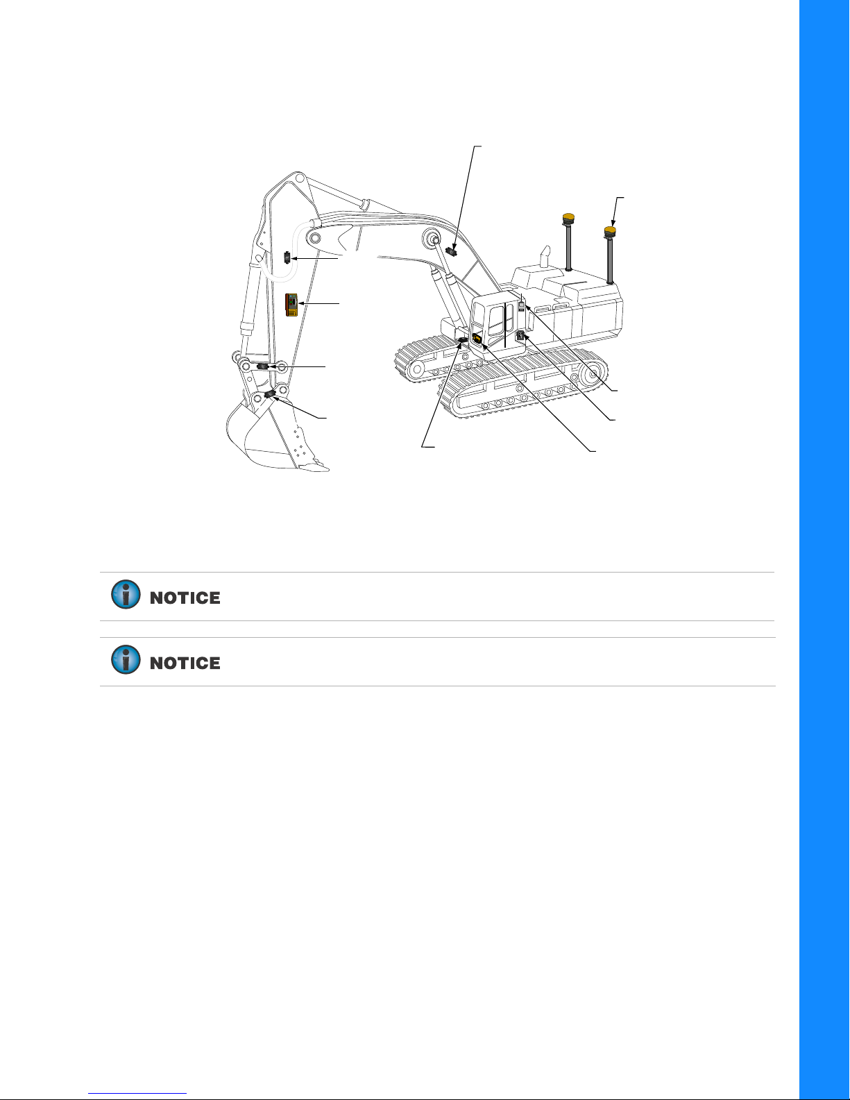
The TS-i3 Tilt Sensors, the MC-X1 Controller, the GX Series display, and the LS-B10W Laser Receiver
Bucket (Hitch)
Sensor
LS-B10W
Laser Receiver
LS-B10W
Laser Receiver
Body Sensor
Boom Sensor
Stick
Sensor
Stick
Sensor
Radio Module
GNSS Antenna 2X
GX Series Display
MC-X1 Controller
Optional
DogBone
Sensor
P/N: 1015925-01
S/N: 1420-XXXXX
make up the 2D indicate system. The LS-B10W adds a laser height reference, and is calibrated for its
location on the stick of the excavator. The 3D system (
Figure 1) utilizes two GR-i3 GNSS Antenna and
a radio module for precise 3D control.
Introduction
Figure 1: Machine Components
When installing components, use the Topcon supplied fuse or fused power
from the machine of the same rating.
System ground must be connected to the frame side of the ground
disconnect switch, not directly to the negative battery terminal.
Indicate System Components
Excavator Indicate System P/N: 1022461-01
2
Page 11
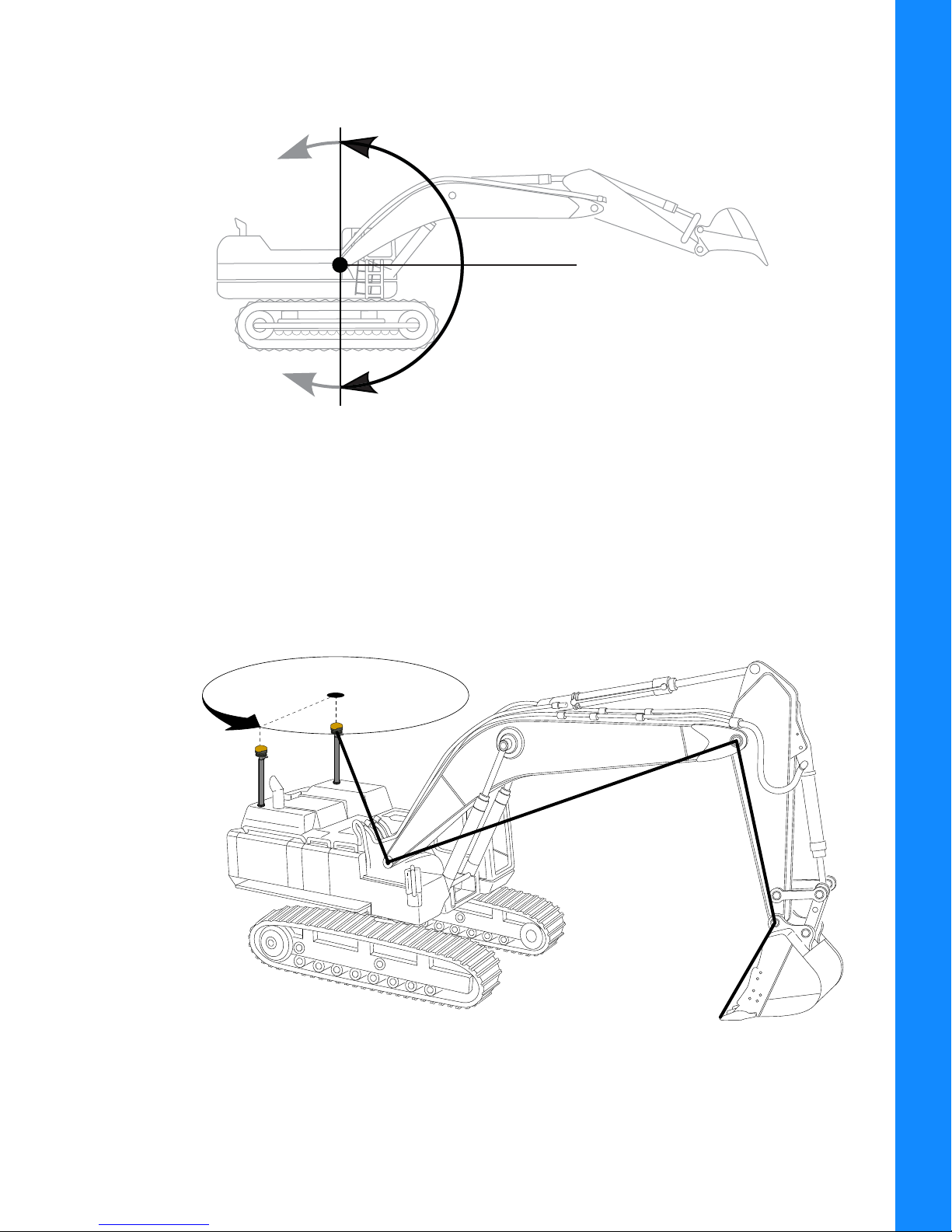
Sitting in the cab facing forward, the sensor angles are 0° straight ahead (horizontal), +90° straight
0°
+90°
-90°
Main Antenna
Position
Aux Antenna
provides
heading
Project position from
Main Antenna to bucket teeth
up, and -90° directly down (
Figure 2).
Figure 2: Angle Convention Used For Tilt Sensors
The Main and Auxiliary (Aux) antennas provide positional and heading information.
Introduction
• Main antenna – determines 3D machine position.
• Aux antenna – determines heading using relative position.
Using TS-i3 sensors, the 3D position of the bucket is projected from the Main antenna.
Figure 3: Tilt Sensor Positional and Heading References
Indicate System Components
Excavator Indicate System P/N: 1022461-01
3
Page 12
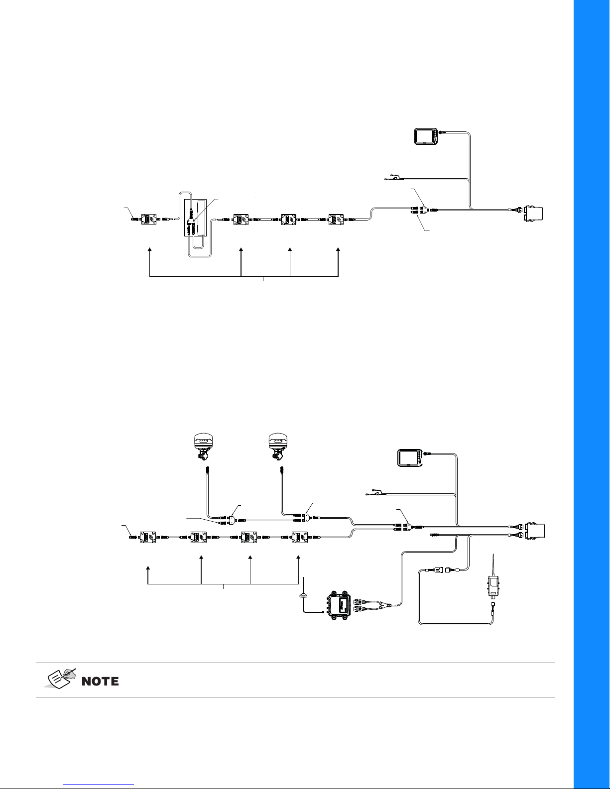
2D System Configuration
+
-
MC-X1
GX SERIES DISPLAY
TS-i3 500 TILT SENSORS
BODY
BOOMSTICK
BUCKET
(HITCH)
CAN open
UNSWITCHED
VOLTAGE SUPPLY
1017652-01
9063-1167-XX
M12 CAN CABLE
4060-0586
SENSOR
TERMINATOR
3020-0623
F-M-M TEE
B
A
LS-B10W
LASER RECEIVER
AND BRACKET
3020-0526
M-M-M TEE
4060-0586
SENSOR
TERMINATOR
GR-i3
ANTENNA
RADIO
+
-
MC-X1
GR-i3
ANTENNA
BODYBOOMSTICKBUCKET
(HITCH)
CAN open
J1939
SERIAL
TS-i3 500 TILT SENSORS
UNSWITCHED
VOLTAGE SUPPLY
1017652-01
1026213-01
1018416-01
3020-0526
M-M-M TEE
9063-1167-XX
M12 CAN CABLE
4060-0586
SENSOR
TERMINATOR
3020-0623
F-M-M TEE
4060-0586
3020-0526
M-M-M TEE
SITELINK
SL-100
B
A
SL-100
SENSOR
TERMINATOR
GX SERIES DISPLAY
Figure 4 shows the basic cabling connections for the 2D excavator indicate system.
Figure 4: Basic Cable Connections - 2D Excavator Indicate System
Introduction
3D System Configuration
Figure 5 shows the basic cabling connections for the 3D excavator indicate system with SL-100.
Figure 5: Basic Cable Connections - SL-100 3D Excavator Indicate System
Indicate System Components
3D configurations may also include the LS-B10W laser receiver. See Figure 4 on
page 4.
Excavator Indicate System P/N: 1022461-01
4
Page 13
MC-X1 Connectivity and Configuration
Configuration of the unit can be done using a GX Series display while connected in the machine, or with
a computer using the following programing cable:
• MC-X1 Program Cable
Connecting to the MC-X Web Interface from a PC
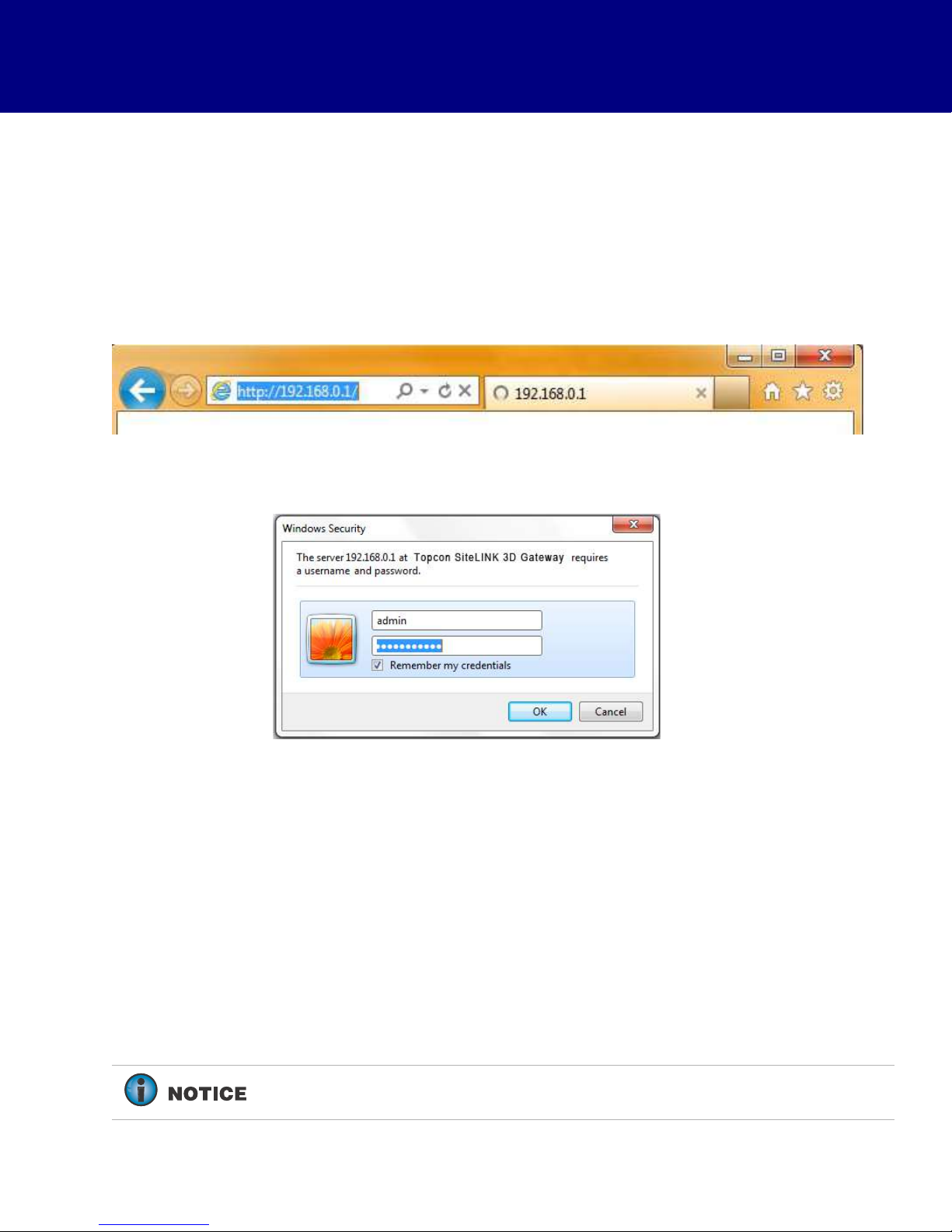
1. Open the web browser on the display or your computer.
2. Type 192.168.0.1 into the address bar to connect to the web interface of the MC-X1 (Figure 6).
Figure 6. Access Topcon Sitelink3D Gateway Web Interface
When prompted for the user name and password, enter admin for both (Figure 7).
Figure 7. Enter Sitelink3D User Name and Password
Connecting to the MC-X Web Interface via MCXCONFIG
MCXCONFIG is also know as the MC-X Machine Control Gateway.
1. Download the MCXCONFIG installer file from myTopcon
(https://www.topconpositioning.com/support).
2. Double-tap on the MCXCONFIG program icon on the desktop of the GX Series display to open the
web interface.
3. When prompted for the user name and password, enter admin for both.
A password is not required in MCXCONFIG 1.0.3.3 or later.
MC-X1 Connectivity and Configuration
Excavator Indicate System P/N: 1022461-01
5
Page 14
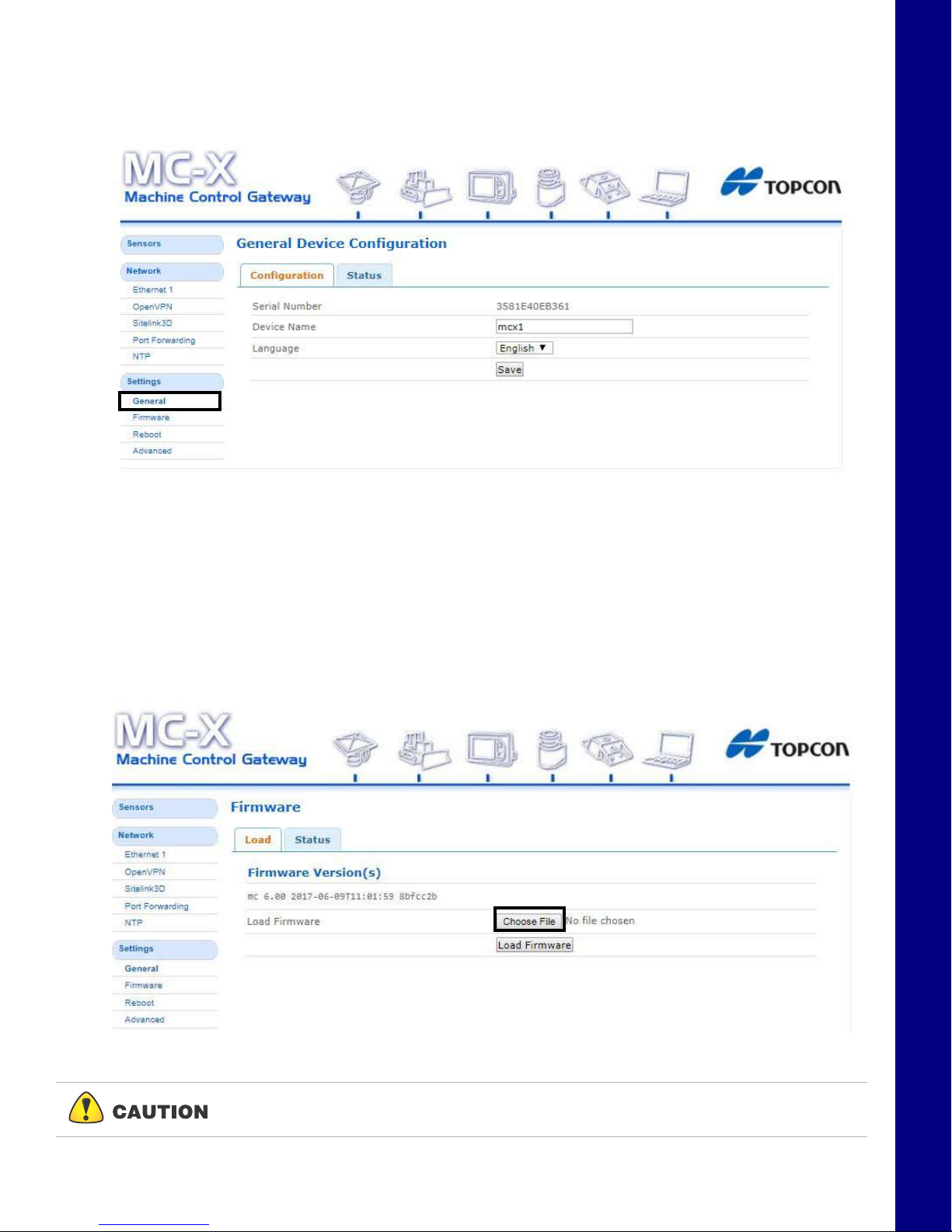
Viewing General Information and Firmware
x
x
From the left menu on the screen, click Settings General. The device information is listed in the
General Device Configuration screen (
Figure 8. General Device Information
Figure 8).
MC-X1 Connectivity and Configuration
Upgrading MC-X1 Firmware
1. To upgrade MC-X1 firmware, click SettingsFirmware.
2. Click the Choose File button. Windows® Explorer appears.
3. Locate and select the appropriate controller firmware for the MC-X1.
4. Click Load Firmware to begin.
Figure 9. Load Firmware - Choose File
Do not close the web browser or power off the system during the firmware upload
process.
Viewing General Information and Firmware
Excavator Indicate System P/N: 1022461-01
6
Page 15
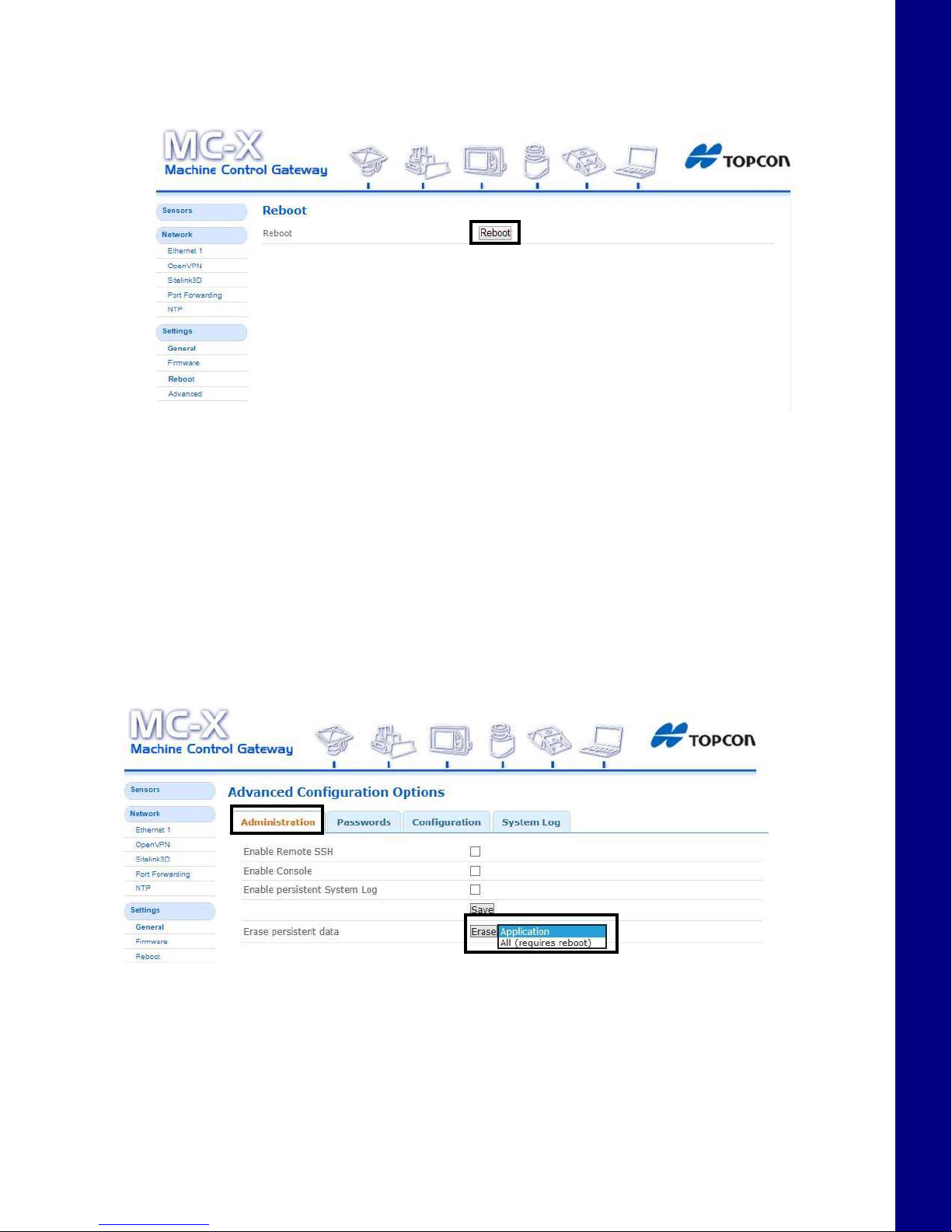
5. Once firmware loading is complete, a reboot prompt appears.
x
6. Click Reboot.
Resetting the MC-X1
If the MC-X1 settings are in an unknown state, all the settings can be reset, which will remove most
settings, including any user defined settings. This step is recommended if the history of the unit is
unknown, or if it has been upgraded from any early beta version of the MC-X1 firmware.
MC-X1 Connectivity and Configuration
Figure 10. Reboot
1. From the menus on the left of the screen, click SettingsAdvanced, and then click the
Administration tab.
2. In Erase persistent data row, select Application from the drop-down list.
3. Click Erase.
Figure 11. Firmware
4. Locate and click the Reboot shortcut link at the top of the screen, or click SettingsReboot
on the left side of the screen.
Resetting the MC-X1
Excavator Indicate System P/N: 1022461-01
7
Page 16
Assigning GR-i3 Vibration Mount to Auxiliary
The Main GR-i3 Vibration Mount must be disconnected from the system in order to assign an
Auxiliary (AUX) antenna.
If Left Pole, Right Pole, GRi3, or AuxGRi3 do not populate in the MC-X Machine
Control Gateway Sensors menu, 3DMC must deploy a machine file with MC-X1 as
Position input.
1. Open 3D-MC to create a machine builder file (if one has not already been created), and select
MC-X1 from the Position input drop-down menu. If a machine builder has already been
configured, make sure MC-X1 is selected as the Position Input.
2. Navigate to the end of the machine builder, and tap Finish.
3. Ensure the correct machine file is selected on the Machine files page, and tap OK. Now, your
.mx3 is deployed, and the necessary sensors will populate in the MC-X Machine Control Gateway
Sensors menu.
An .mx3 file that is active in 3D-MC is considered the “deployment”.
MC-X1 Connectivity and Configuration
4. Open MCXCONFIG.
5. Disconnect the CAN cable from the bottom of the Main GR-i3 Vibration Mount on the Left side of
the machine.
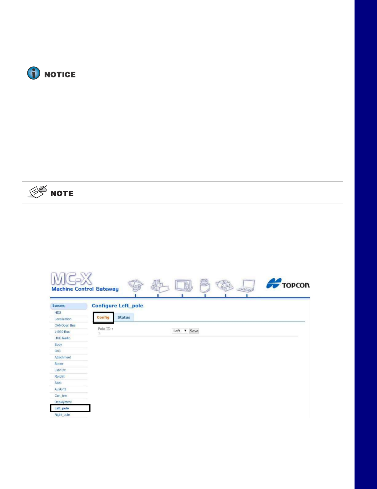
6. From the menus on the left of the screen, click Sensors > Left_pole, and then click the Config
tab..
Figure 12. Settings - Left Pole - Config Tab
7. Selec t Right from the drop-down menu (Figure 13).
Assigning GR-i3 Vibration Mount to Auxiliary
Excavator Indicate System P/N: 1022461-01
8
Page 17

8. Tap Save. The GR-i3 Vibration Mount is set to AUX.
Figure 13. Right
9. Reconnect the CAN cable to the main GR-i3 Vibration Mount on the Left side of the machine.
MC-X1 Connectivity and Configuration
The GR-i3 units are not assigned Main or AUX. Only a Vibration Mount may be
assigned to be AUX. The GR-i3s remain interchangeable.
Loading GR-i3 Firmware
1. Select the GR-i3 menu under Sensors.
Loading GR-i3 Firmware
Figure 14. Sensors - GR-i3
Excavator Indicate System P/N: 1022461-01
9
Page 18

2. Select the Firmware Upgrade tab.
Figure 15. Firmware Upgrade
MC-X1 Connectivity and Configuration
3. Select Choose File (Figure 16) and navigate to the GR-i3 firmware file (.bin extension).
4. Choose Upgrade and the firmware upgrade process should begin (Figure 16).
Figure 16. Choose File
Loading GR-i3 Firmware
Excavator Indicate System P/N: 1022461-01
10
Page 19
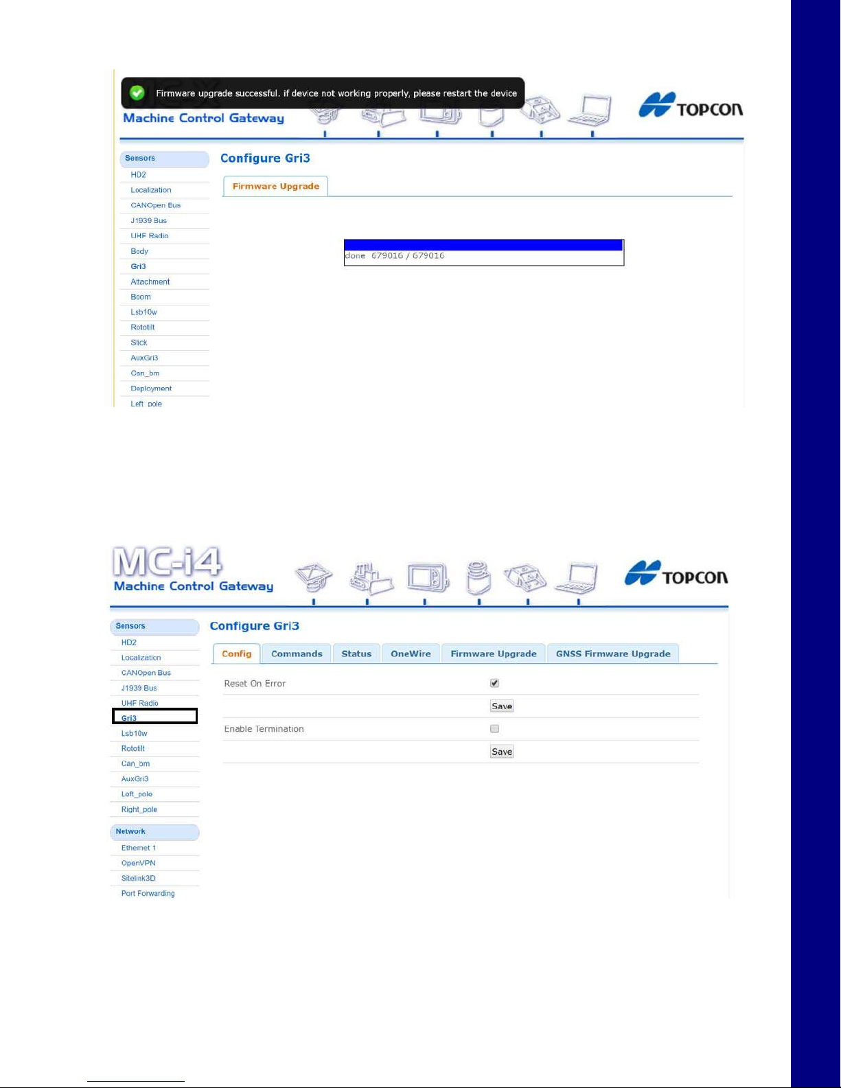
A notification appears once the upgrade process is complete (Figure 17).
Figure 17. Firmware Upgrade Successful
MC-X1 Connectivity and Configuration
5. Select AuxGRi3 under the Sensors tab, and repeat steps 2 through 4 for the Auxiliary antenna.
Loading GNSS Firmware
1. Select the GR-i3 menu under Sensors.
Figure 18. GNSS Firmware - GR-i3
Loading GNSS Firmware
Excavator Indicate System P/N: 1022461-01
11
Page 20
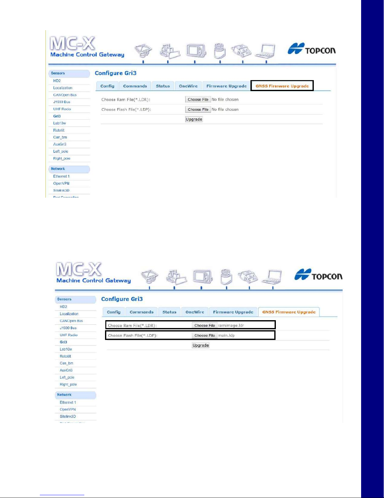
2. Select the GNSS Firmware Upgrade tab.
Figure 19. GNSS Firmware Upgrade Tab
MC-X1 Connectivity and Configuration
3. To choose the RAM file, select Choose File and navigate to the GR-i3 firmware file
(.ldr extension).
4. To choose the Flash file, select Choose File and navigate to the GR-i3 firmware file
(.ldp extension).
Figure 20. GNSS Firmware - Choose File
Loading GNSS Firmware
Excavator Indicate System P/N: 1022461-01
12
Page 21
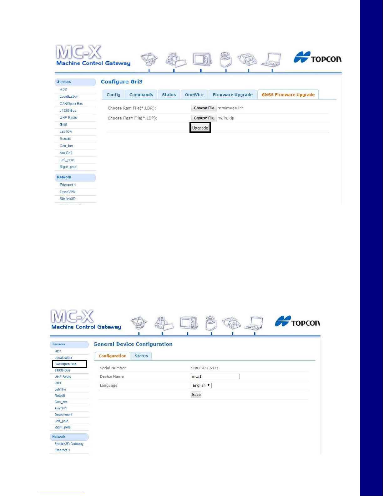
5. Choose Upgrade and the firmware upgrade process should begin. A notification appears once
the upgrade process is complete.
MC-X1 Connectivity and Configuration
6. Select AuxGRi3 under the Sensors tab, and repeat steps 2 through 5 for the Auxiliary antenna.
System Verification
Now that all necessary firmware has been loaded onto the MC-X1, CAN communication can be
verified.
1. Ensure all sensors and GR-i3s are connected, then tap on CANOpen Bus.
Figure 21. GNSS Firmware - Upgrade
System Verification
Figure 22. CANOpen Bus
Excavator Indicate System P/N: 1022461-01
13
Page 22
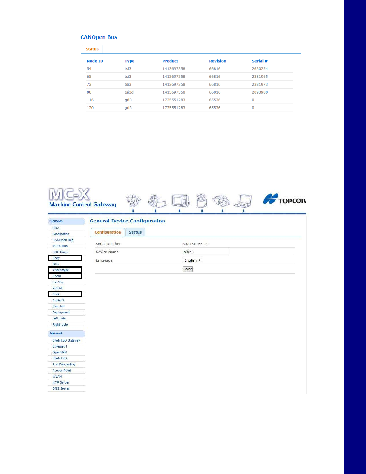
2. All communicating devices will populate in the Status window (Figure 23).
Figure 23. CANOpen Bus - Communicating Devices Status
Once a machine builder has been made active with the correct sensor designations (see
“Calibration” on page 44), the Body, Boom, Stick, and Attachment will be selectable in the
Sensors menu as shown in Figure 24 on page 14.
MC-X1 Connectivity and Configuration
Figure 24. CANOpen Bus - Communicating Devices Status
System Verification
Excavator Indicate System P/N: 1022461-01
14
Page 23
Loading EASy-Proof Radio Channels
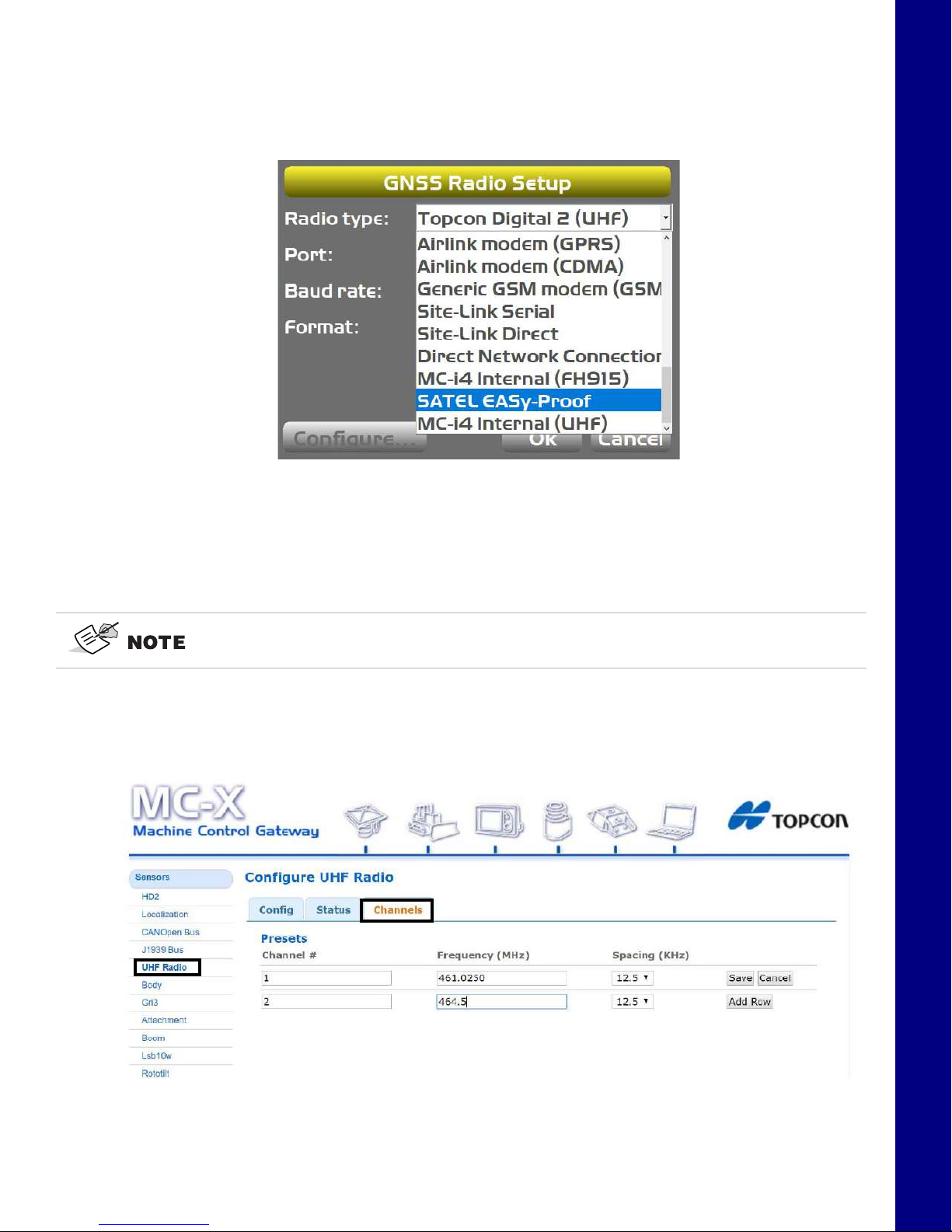
1. Open 3D-MC to create a machine builder file (if one has not already been created), and select
Satel EASy-Proof from the radio drop-down menu. If a machine builder has already been
configured, make sure Satel EASy-Proof is selected as the radio type.
Figure 25. UHF Radio Setup
MC-X1 Connectivity and Configuration
2. Navigate to the end of the machine builder, and tap Finish.
3. Ensure the correct machine file is selected on the Machine files page, and Tap OK.
Now, your .mx3 is deployed, and the radio will populate in the MC-X Machine Control Gateway.
An .mx3 file that is active in 3D-MC is considered the “deployment”.
4. UHF RADIO will not populate in the MC-X Web Interface unless an .mx3 file with the Satel
EASy-Proof radio type is deployed from 3D-MC.
5. Open MCXCONFIG, and select UHF Radio under Sensors.
Loading EASy-Proof Radio Channels
Figure 26. UHF Radio Setup
Excavator Indicate System P/N: 1022461-01
15
Page 24
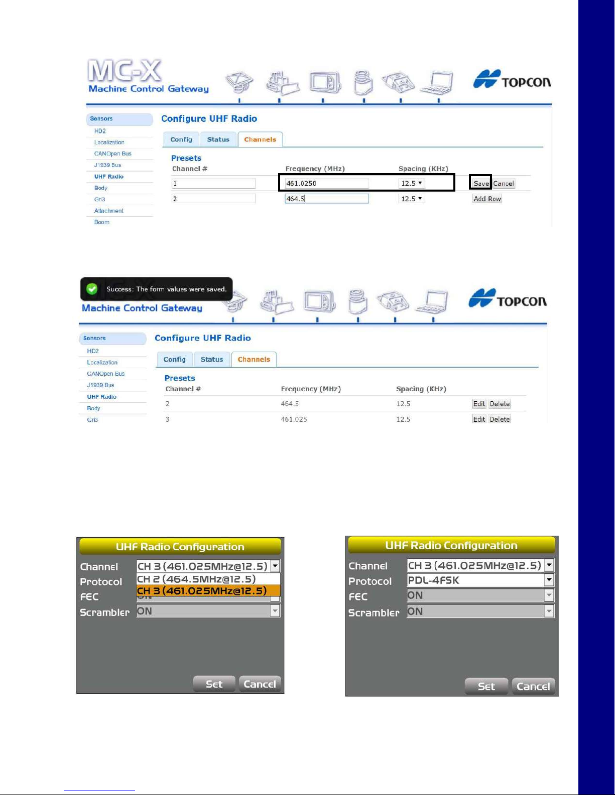
6. Tap the Channels tab, enter the appropriate values, and tap Save.
Figure 27. UHF Radio Setup
Anotificationappearswhenthevaluesaresaved(Figure28).
MC-X1 Connectivity and Configuration
Figure 28. UHF Radio Setup - Saved
7. Close MCXCONFIG.
8. Open 3D-MC, and tap Tools > Configure Radios > Configure, and then select the
appropriate channel from the drop-down menu.
9. Tap Set.
Figure 29. UHF Radio Configuration
Loading EASy-Proof Radio Channels
Excavator Indicate System P/N: 1022461-01
16
Page 25
Factory Reset for the GR-i3 via TRU
A Factory Reset resets all the receiver parameters to their default values and clears the receiver's NonVolatile Random Access Memory (NVRAM). NVRAM holds data required for satellite tracking. Factory
Reset does not delete any files from the receiver and does not reset modem parameters.
Perform a Factory Reset after loading a new GNSS firmware file and sometimes to eliminate
communication or tracking problems. After performing the procedure, the receiver requires some time
to collect new ephemerids and almanacs (up to 15 minutes)
To perform a Factory Reset using Topcon Receiver Utility (TRU):
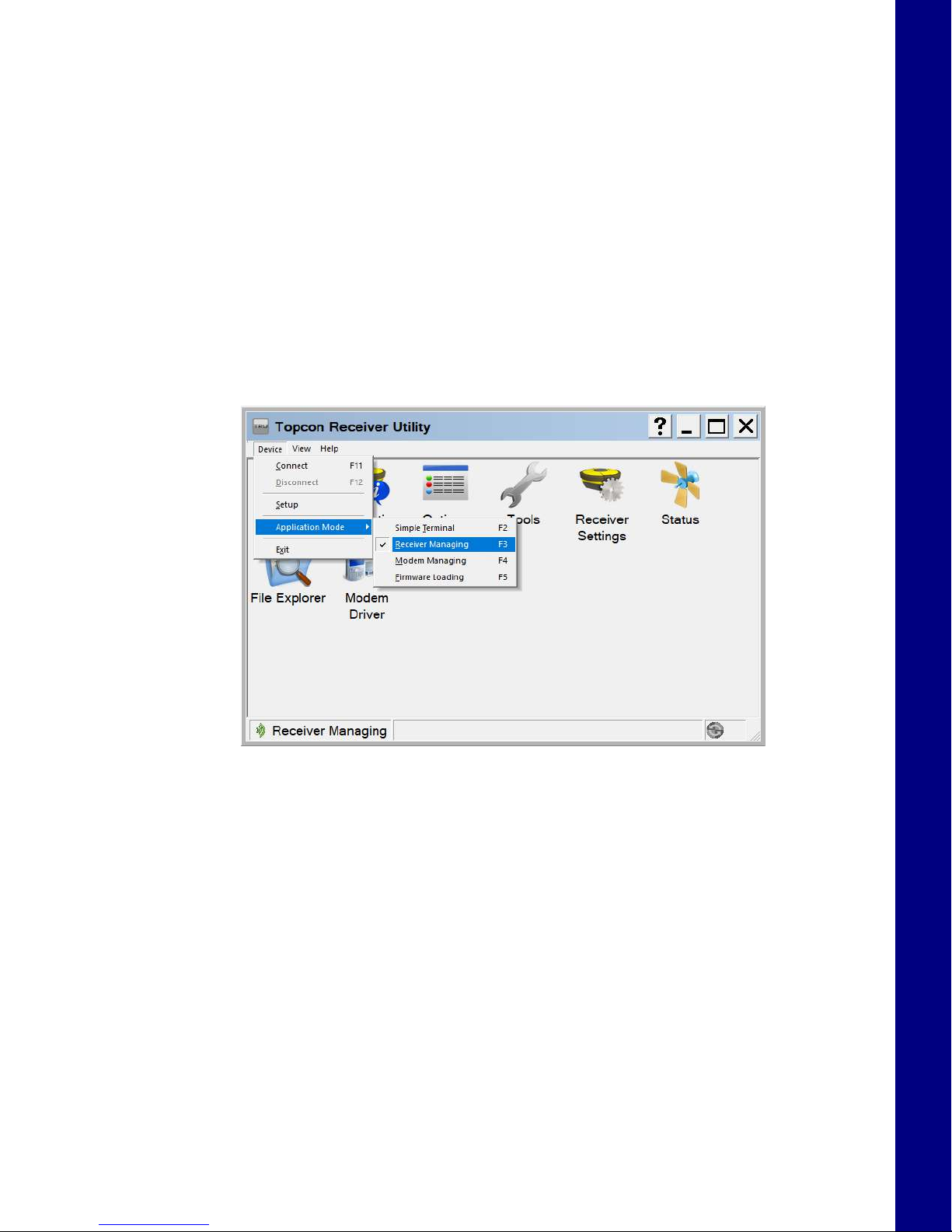
1. Open TRU from the desktop of the GX Series display.
2. Tap Device > Application Mode > Receiver Managing.
MC-X1 Connectivity and Configuration
3. Tap Device > Connect.
Factory Reset for the GR-i3 via TRU
Figure 30. TRU - Receiver Managing
Excavator Indicate System P/N: 1022461-01
17
Page 26
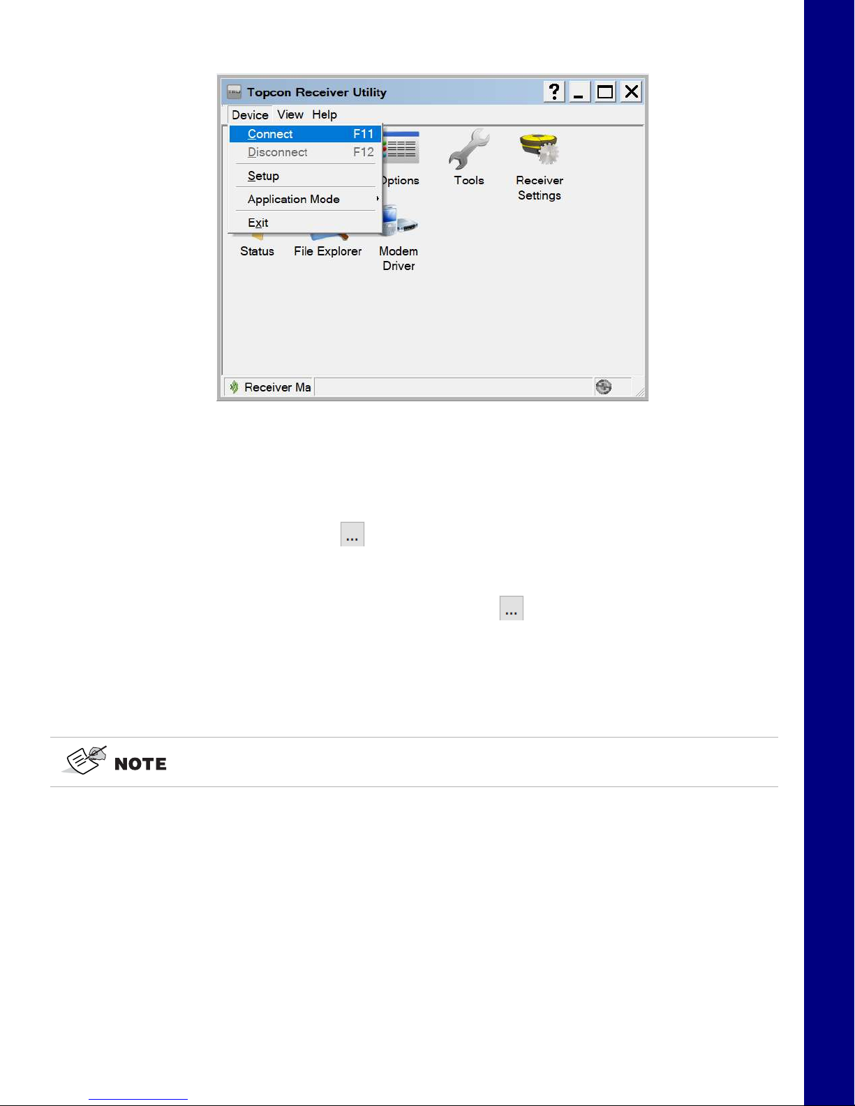
Figure 31. TRU - Connect
MC-X1 Connectivity and Configuration
4. In the Connection Parameters screen, select Network from the Connect Using drop-down
list.
5. In the Device Name field, tap to select the device name to which the GPS receiver board is
connected.
a. If a Device name has not been configured, tap . Then press and hold on the white
area of the screen.
b. Select Add. The Network Connection screen appears.
c. Enter a Name to identify the Main GNSS board
MC-i3, MC-i4, and the GR-i3 utilize the same network parameters for Main and AUX
GNSS boards.
d. Enter the following network parameters for the GR-i3 Main GPS board:
– IP Address or Host Name: 192.168.0.1
– TCP Port: 8012
– Password: TPS
e. Tap Ok.
Factory Reset for the GR-i3 via TRU
Excavator Indicate System P/N: 1022461-01
18
Page 27

6. After resetting the Main GNSS board, repeat steps 3 to 5e for the Auxiliary GNSS board.
The TCP Port for the Auxiliary GNSS board is 8013.
MC-X1 Connectivity and Configuration
Figure 32. TRU - Network Parameters
7. Tap Connect.
8. Tap the Tools icon .
9. Select Factory Reset.
10. A popup message appears. Tap OK.
11. After both GNSS boards have been reset, close TRU.
Factory Reset for the GR-i3 via TRU
Excavator Indicate System P/N: 1022461-01
19
Page 28

Configuring SL-100 for MC-X1 Communication
The following section explains how to configure the optional SL-100 for communication with the
MC-X1.
To communicate with the MC-X1, SL-100 Firmware 1.15 must be installed on the SL-100. Refer to the
SL-100 Configuration Manual
Firmware cannot be loaded while the SL-100 is connected to the MC-X1. SL-100
programming cables are necessary.
Once the SL-100 is connected, the Sitelink3D Gateway is accessible under Network.
P/N: 1000226-01 to load the firmware.
MC-X1 Connectivity and Configuration
Figure 33. Sitelink3D Gateway
To return to the MC-X Machine Control Gateway, click Back.
Configuring SL-100 for MC-X1 Communication
Excavator Indicate System P/N: 1022461-01
20
Page 29

Installation
TS-i3 Sensors
Before installation, note the following:
Each TS-i3 sensor contains a single or dual axis sensor element. The sensor’s mounting location
determines the sensor type; single axis or dual axis. Single axis sensors mount on the stick, boom, and
attachment, in a left or right orientation. The body sensor is dual axis, and mounts only in a flat
orientation with the label up.
• Check the sensor’s serial numbers before installing. The last two digits of the
serial number determine the sensor CAN address, and must be unique to each
machine.
• A sensor ending in 00 is considered a special CAN identifier, and will be
identified as 01 in 3D-MC; therefore; if you have a sensor with 00 and a sensor
with 01, there will be some confusion in 3D-MC.For example, sensor serial
number 0302 and 0402 will have the same CAN address (“02”), causing
communication errors.
When mounting the tilt sensors, begin with the attachment to help simplify cable
routing.
The dual axis TS-i3 sensor is labeled “TS-i3d”.
When installing the sensors, ensure that they are mounted parallel to the axis being measured. Locate
surfaces that protect the sensor from physical damage and are convenient for cable routing. When the
posit ion of the im pleme nt is a t zero degree s (hor izont al), m ake a n ote of the di rect ion of the ar row marke r
on the serial label (located on the top of the sensor). This direction is needed during calibration. The
calibration process uses 3D-MC to enter direction, orientation, and other sensor variables.
Installation
Excavator Indicate System P/N: 1022461-01
21
Page 30

TS-i3 Sensor Orientation
Figure 34: TS-i3 Sensor Location and Direction
Mounting each tilt sensor within +/- 20° of the pivot centerline is a good practice.
Though not necessary for system performance, squaring the sensors to each part of
the machine makes for a cleaner looking installation.
All tilt sensor orientation is determined when the implement is horizontal (zero
degrees). The orientation of each tilt sensor is entered in 3D-MC.
It is recommended that the sensors be installed on the boom, stick and attachment
implements with serial numbers in ascending or descending order.
Installation
When entering sensor information, make note of each sensor’s serial number and
its orientation. TS-i3 sensor orientation for boom, stick, and hitch is only left or
right.
TS-i3 Sensors
Excavator Indicate System P/N: 1022461-01
22
Page 31

CAN Termination
BODY
BOOMSTICK
BUCKET
(HITCH)
4060-0586
SENSOR
TERMINATOR
+
-
MC-X1
CAN open
UNSWITCHED
VOLTAGE SUPPLY
1017652-01
3020-0623
F-M-M TEE
4060-0586
B
A
SENSOR
TERMINATOR
GX SERIES DISPLAY
GR-i3
ANTENNA
GR-i3
ANTENNA
3020-0526
M-M-M TEE
4060-0586
SENSOR
TERMINATOR
3020-0526
M-M-M TEE
+
-
MC-X1
GX SERIES DISPLAY
CAN open
UNSWITCHED
VOLTAGE SUPPLY
1017652-01
3020-0623
F-M-M TEE
B
A
To ensure proper communication on the CAN bus, the last sensor physically connected must use the
hard terminator provided with the excavator systems. Typically, the hard terminator connects to the
hitch sensor or the tilt bucket sensor as shown in
Figure 35: Hard Terminator on Last TS-i3 Sensor
On a 2D system, the hard terminator must also connect to the F-M-M Tee (Figure 36).
Installation
Figure 35.
Figure 36: Hard Terminator on F-M-M Tee - 2D System
On a 3D system, the hard terminator must also connect to the M-M-M Tee at the last GR-i3 (usually
the AUX), as shown in
CAN Termination
Figure 37,
Figure 37: Hard Terminator M-M-M Tee - 3D System
Excavator Indicate System P/N: 1022461-01
23
Page 32

Hitch Sensor
The hitch sensor is the most challenging sensor to mount to keep the sensor and cables protected.
If a quick release coupler is installed on the excavator, the most accurate and safe place to mount the
sensor is on the inside of the coupler
An alternative mounting location is on the left side of the DogBone, either on the inside or the outside
of the DogBone itself; see
“DogBone Sensor (Optional Mounting Location)” on page 25.
If no hitch sensor is used select None (hanging attachment).
TS-i3 sensors are only mounted on the left or right of the DogBone or
quick-release.
When mounting the attachment sensor, keep the following in mind (Figure 38):
• Position the hitch on the ground (bucket flat on the ground) before mounting the sensor.
• Mount the sensor between the attachment pivot pin and the linkage pin as shown in Figure 38.
.
Installation
• Sensor is orientation Left/Right.
Correct
Quick-release Coupler
Mounting
Orientation
Correct
Attachment
Mounting
Orientation
Figure 38: Quick-release and Attachment Sensor Mounting
CAN Termination
Excavator Indicate System P/N: 1022461-01
24
Page 33

DogBone Sensor (Optional Mounting Location)
Correct Mounting
Orientation
An optional location for the hitch sensor is on the DogBone. This location offers additional protection
of the sensor, but produces less accurate readings (especially if the joints are worn). If possible,
placing the sensor on the inside of the DogBone will provide additional protection. Mounting the
sensor on the DogBone requires additional calibration steps.
Installing the sensor on the inside of the DogBone may not be possible on
smaller machines due to space constrictions.
If using the DogBone mounting option, worn joints in the DogBone linkage
causes decreased accuracy.
TS-i3 sensors are only mounted on the left or right of the DogBone.
The recommended location of the sensor is on the left side of the DogBone.
Installation
Figure 39: DogBone Sensor Mounting Example
CAN Termination
Excavator Indicate System P/N: 1022461-01
25
Page 34

Tilt Bucket Sensor
Single-axis TS-i3 Sensor Orientation Dual-axis TS-i3d Sensor Orientation
If using tilt bucket, an additional sensor may be mounted to the bucket (Figure 40). Ti lt bucket sensor
mounting differs from all other sensors. Determine the location and orientation of the sensor with the
bucket sitting flat on the ground.
If using a single-axis TS-i3 sensor, mount the sensor vertically, with the
label front/arrow right, or label back/arrow right from the cab
perspective.
If using a dual-axis TS-i3d sensor, mount the sensor with a flat
orientation, on a the top of the attachment with the label up. The arrow
may point left, right, forward, or back.
Installation
Figure 40: Tilt Bucket Sensor Mounting
Tilt Rotator
The following brands of supported Tilting/Rotating attachments include;
• Rototilt
• Engcon
• Steelwrist
Each manufacturer has specific installation documentation which is required for setup and calibration.
CAN Termination
®
®
®
Excavator Indicate System P/N: 1022461-01
26
Page 35

Stick Sensor
Locate a convenient surface to mount the sensor. Mounting the sensor close to the top of the stick
will help prevent damage during digging.
The mounting location shall be on the left or right side of the stick (from the cab point of view).
Correct Side
Location
Installation
CAN Termination
Figure 41: TS-i3 Stick Sensor Mounting
Excavator Indicate System P/N: 1022461-01
27
Page 36

Boom Sensor
CL
Correct
Parallel Location
CL
Incorrect
Taper Location
Direction of Travel ( Away from Cab)
For the boom sensor, locate a convenient surface parallel to the boom center. The mounting location
may be on the left or right side of the boom (from the cab point of view). Be sure to place the sensor
at a location away from the boom pivot
Placing the boom sensor on a tapered section will cause calculation errors.
Installation
Figure 42: Boom Sensor Mounting
Secondary Boom Sensor
The secondary boom sensor mounting locations are identical to the primary boom sensor mounting
locations. If a second boom is installed, see the previous section
“Boom Sensor” on page 28.
CAN Termination
Excavator Indicate System P/N: 1022461-01
28
Page 37

Body Sensor
For the TS-i3d dual axis body sensor, locate a convenient surface where the sensor can be mounted
with the label up.
The recommended mounting location is between the boom’s elevation cylinders (Figure 43).
If a secure mounting surface cannot be between the boom’s elevation cylinders, mount the body
sensor to the alternative mounting location on top of the body, or under the boom pivot pin.
Recommended
Location
Body Sensor
Boom Pivot
Body Sensor
Installation
LS-B10W
The LS-B10W Laser Receiver and bracket must be mounted on the left side of the stick. The following
section describes bracket mounting, cable routing, and LS-B10W Laser Receiver mounting.
1. Before installing the LS-B10W bracket, you must assemble the bracket kit; see the
Indexing Bracket Assembly Instructions
Alternate
Location
Figure 43: Body Sensor Mounting - Top View
A mark on the laser receiver and the cross hairs on the mounting bracket
are used to determine its position on the stick.
LS-B10W
(p/n: 7030-1370) for more information.
When determining mounting location, be cautious of limitations in cable
lengths.
2. Install the LS-B10W onto the bracket.
LS-B10W
Excavator Indicate System P/N: 1022461-01
29
Page 38

3. Route the cables as shown in Figure 44.
LS-B10W Laser Receiver
LS-B10W Cable
Attachment Sensor Cable
Stick Sensor Cable
Installation
Figure 44: LS-B10W Cable Routing
MC-X1 Controller
Install the MC-X1 Controller onto the machine’s body using the magnet mounts provided, and connect
the cable to the GX Series Display.
S-B10W Laser Receiver Setup
MC-X1 Controller
Excavator Indicate System P/N: 1022461-01
30
Page 39

GNSS Antenna, Mount and Pole
Weld Mount
Locations on Counterweight
1. Weld the Antenna Pole Weld Mount to the top of the counterweight as shown in Figure 45.
Various makes and models may require fabrication of mounting surface for
the Antenna Pole Mount. Ensure that the top of the antenna is flush or
slightly above the cab roof when mounted.
Installation
Figure 45: Antenna Pole Mount Weld Mount Locations
2. Repeat Step 1 on the opposite side of the excavator.
3. Install the two antenna poles onto the weld mount using the three (3) bolts as shown in
Figure 46.
GNSS Antenna, Mount and Pole
Excavator Indicate System P/N: 1022461-01
31
Page 40

Installation
Mast
Weld Mount
Figure 46: Antenna Pole Installed
4. Install the strain relief brackets. Remove the two (2) small bolts to route the TURK CAN cable
through the bracket. Ensure enough cable is routed through, so that the cable can be threaded
into the GR-i3 BASE (
Figure 48 on page 33).
GNSS Antenna, Mount and Pole
Figure 47: Strain Relief
Excavator Indicate System P/N: 1022461-01
32
Page 41

5. Install the GNSS antenna, align the strain relief bracket, and connect the cable (Figure 48 on
GR-I3 GNSS Antenna
Mast
Strain Relief Bracket
Cable
Antenna Vibration Mount
Weld Mount
Bolt 3X
page 33).
Installation
Figure 48: GNSS Antenna Installed on Pole
WiFi Antenna and Magnet Mount (If Purchased)
1. Install the WiFi Antenna Magnet Mount onto the machine’s cab.
2. Install the WiFi Antenna onto the Magnet Mount.
3. Connect the WiFi Antenna cable to the MC-X1.
WiFi Antenna and Magnet Mount (If Purchased)
Excavator Indicate System P/N: 1022461-01
33
Page 42

Machine Measurements and Configuration
GR-i3F GNSS Antennas
GR-i3F GNSS Antenna
Heights
Note: Take the
Antenna Above
measurement from
the bottom of the
GR-i3 (the top of
the Vibration
Mount).
Boom/Body (1)
ĞŶƚĞƌŽĨZŽƚĂƟŽŶ
Taking Machine Measurements
Accurately measure and enter the machine dimensions into the 3D-MC machine builder, and write your
measurements on the lines at the side of the following screen captures.
Incorrect measurements or data entry errors have a direct affect on excavating
accuracy. Take each measurement twice to ensure accuracy.
GR-i3
Machine Measurements and Configuration
Excavator Indicate System P/N: 1022461-01
34
Page 43

Body and Boom
Boom Length
Secondary Boom Length
Boom Sensor ID
Body Sensor ID
ΘKƌŝĞŶƚĂƟŽŶ
Secondary
Boom Sensor ID
^ƟĐŬ>ĞŶŐƚŚ
^ƟĐŬ^ĞŶƐŽƌ/
Hitch Sensor ID
DŽƵŶƟŶŐ>ŽĐĂƟŽŶ
The Hitch Sensor may
be mounted on the
Dogbone or the
Hitch/Coupling.
Hanging Attachment
may be selected if
there is no sensor.
Stick
Machine Measurements and Configuration
Hitch
Taking Machine Measurements
Excavator Indicate System P/N: 1022461-01
35
Page 44

DogBone
ƩĂĐŚŵĞŶƚtŝĚƚŚĂŶĚ>ĞŶŐƚŚ
;ƌĞƉĞĂƚĞĚĨŽƌĞĂĐŚďƵĐŬĞƚͿ
EŽƚĞDƵůƟƉůĞĂƩĂĐŚŵĞŶƚƐŵĂLJ
ďĞƐĞƚƵƉĂƚĂŶLJƟŵĞtŚĞŶ
ƌĞĂĚLJĨŽƌƵƐĞĞŶƐƵƌĞƚŚĂƚƚŚĞ
ĚĞƐŝƌĞĚĂƩĂĐŚŵĞŶƚŝƐĐĂůŝďƌĂƚĞĚ
;ƐĞĞƉŐϯϱͿ
ZĞĐŽƌĚ^ĞŶƐŽƌ/ĂŶĚŽƌŝĞŶƚĂƟŽŶ
ĨŽƌĂůůƐĞŶƐŽƌƐ
Note: Length 3 is the length
ĨƌŽŵƚŚĞĂƩĂĐŚŵĞŶƚƉŝǀŽƚ
ƉŝŶƉĞƌƉĞŶĚŝĐƵůĂƌƚŽƚŚĞƟůƚ
ƉŝǀŽƚƉŝŶ/ĨƚŚŝƐŵĞĂƐƵƌĞŵĞŶƚŝƐŝŶĐŽƌƌĞĐƚƚŚĞ
ĂĐĐƵƌĂĐLJŽĨƚŚĞĂƩĂĐŚŵĞŶƚ
ǁŝůůďĞĚĞŐƌĂĚĞĚĂƐŝƚŝƐ
ƟůƚĞĚ
^ĞŶƐŽƌ/
ΘKƌŝĞŶƚĂƟŽŶ
ƩĂĐŚŵĞŶƚ^ĞƚƵƉ
ƵĐŬĞƚZŽƚĂƚŽƌ
^ĞŶƐŽƌ/
DogBone Lengths
Attachments
Machine Measurements and Configuration
,ŝƚĐŚ^ĞŶƐŽƌ/
EŽƚĞ^ƟĐŬĂŶŐůĞĚŝīĞƌĞŶĐĞ;ŝīͿŝƐ
ĚĞƚĞƌŵŝŶĞĚĚƵƌŝŶŐĐĂůŝďƌĂƟŽŶŽĨƚŚĞ
ŵĂĐŚŝŶĞ
Taking Machine Measurements
Excavator Indicate System P/N: 1022461-01
36
Page 45

Machine Measurements and Configuration
ƩĂĐŚŵĞŶƚ^ĞƚƵƉ
ůĂŵƐŚĞůůƵĐŬĞƚ
ƩĂĐŚŵĞŶƚ^ĞƚƵƉ
dƌĂƉĞnjŽŝĚĂůƵĐŬĞƚ
ƩĂĐŚŵĞŶƚ^ĞƚƵƉ
'ƌŝŶĚŝŶŐtŚĞĞů
ĞƉƚŚĨƌŽŵĞŶƚĞƌůŝŶĞŽĨ^ƟĐŬ
Distance from Bucket Pivot
to LSB10W
Distance from Left of Pivot
Angle to the Stick Centerline
Note: Only determinded during
calibration of the machine.
LS-B10W
Taking Machine Measurements
Excavator Indicate System P/N: 1022461-01
37
Page 46

Entering Sensor Information
Power up the system and allow several minutes for the 3D-MC software to detect the sensors.
Before calibrating the sensors on the excavator systems, set up each sensor in 3D-MC. You will need
the following information:
• the last two digits of the sensor’s serial number
• the physical orientation of the sensor mounting
Step 1: Configure the Machine File and the excavator options.
1. In the GX Series display, tap the Power ButtonControlMachine setup.
2. Select a current machine file and tap Edit, or tap New to create a new machine file.
3. On the Configuration name/type screen, enter or select the appropriate data as needed
(
Figure 49).
Machine Measurements and Configuration
Figure 49: Configuration name/type
4. Tap Next to navigate to the Excavator Options screen and select None as the Position
Input (
5. Enter 3D/2D excavator options:
Figure 50 on page 39).
a. For 3D systems, choose MC-X1 for Position Input and Sensor Input.
b. For 2D systems, select MC-X1 for Sensor Input.
Entering Sensor Information
Excavator Indicate System P/N: 1022461-01
38
Page 47

Figure 50: Select the Appropriate Position and Sensor Input
6. Enter 3D/2D sensor values:
a. For 3D systems, tap Next to navigate to the Excavator Antenna Mounting screen,
followed by the Excavator Antenna Heights screen. Enter the appropriate values as
needed on both screens.
Machine Measurements and Configuration
b. For 2D systems tap Next to navigate to the Excavator IMU Mounting screen, and
select the appropriate values as needed.
Then tap Next to navigate to the Boom /
Body (1) screen. Enter the appropriate values.
7. If using a TS-i4 as a compass, select TS-i4 from the drop-down menu. Then tap the Wrench
icon to calibrate the compass. Follow the on-screen instructions.
8. Tap Next to navigate to the Boom / Body (2) screen. Enter the appropriate value.
Step 2: Designate each sensor to its corresponding implement.
If using a TS-i4, TS-i4-IMU will be selected as the Sensor ID for the body.
For the Body, Boom, Stick, and Attachment sensors, Tap the appropriate
Sensor ID box and select the serial number (last two digits) of the sensor
corresponding to the machine element. Refer to your notes from installation
to select the correct sensor ID from the drop-down menu.
Entering Sensor Information
Excavator Indicate System P/N: 1022461-01
39
Page 48

1. Tap Next to navigate to the Excavator Frame/Sensor screen (Figure 51).
Figure 51: Select Body and Boom Sensor ID
2. Tap the appropriate Sensor ID box and select the serial number (last two digits) of the sensor
corresponding to the machine element.
3. Enter the appropriate values.
Machine Measurements and Configuration
4. Tap Next to access the Excavator Stick screen.
Figure 52: Select Stick Sensor ID
5. Enter the appropriate values, and select the corresponding sensor.
Entering Sensor Information
Excavator Indicate System P/N: 1022461-01
40
Page 49

6. Tap Next to access the Excavator Hitch screen.
Figure 53: Select Bucket Sensor ID
7. Enter the appropriate values, and select corresponding sensor.
8. Tap Next to access the Excavator Attachments screen.
a. Tap New to access the Excavator Attachment Setup screen.
Machine Measurements and Configuration
b. Enter or select the appropriate data as needed.
Figure 54: Excavator Attachments
c. Press Next to access the Calibrate Attachment Angle screen (calibration performed
in next chapter).
d. Press Next to access the Calibrate Bucket Base screen (calibration performed in next
chapter).
e. Press Finish to access the Excavator Attachments screen.
f. Repeat Steps a through e for each attachment.
Entering Sensor Information
Excavator Indicate System P/N: 1022461-01
41
Page 50

Audible Guidance
1. Tap Next to access the Audible Guidance screen.
2. Enter the desired Tone and Duration settings.
Lightbars
Machine Measurements and Configuration
Figure 55: Audible Guidance
1. Tap Next to access the Light Bars screen.
2. Enter the desired settings.
Figure 56: Lightbars
Audible Guidance
Excavator Indicate System P/N: 1022461-01
42
Page 51

Configuration Complete
1. Tap Next to access the Configuration Complete! screen.
2. Press Finish to save configuration, or press Cancel to return to the Machine Files screen
without saving.
Machine Measurements and Configuration
Figure 57: Configuration complete!
Configuration Complete
Excavator Indicate System P/N: 1022461-01
43
Page 52

Calibration
Before calibrating the sensors, note the following:
Sensor Filtering
The filter level for each sensor can be changed depending on the application and operator’s choice. A
value of 4 (heavy filtering) will dampen sensor reaction, while a value of 1 (light filtering) will cause faster
sensor reaction.
If using the DogBone mounting option, worn joints in the DogBone linkage will
cause decreased accuracy.
The best practice is to perform the machine calibrations as ordered in this
manual. Performing the calibrations out of order will not affect system
performance.
There are two exceptions to this rule when using a DogBone sensor:
a. You must calibrate the stick sensor before calibrating the DogBone sensor.
b. When using a tilt bucket sensor you must calibrate the attachment/DogBone
sensor before calibrating the tilt bucket sensor.
1. On the GX Series display, tap the Power ButtonControlMachine setup. Select the applicable
machine file and tap Edit. Tap Next to navigate to the Excavator Frame/Sensors screen,
Excavator Stick screen, or the Excavator Hitch screen.
2. Tap the Wrench icon next to Sensor ID (Figure 58).
3. Select a filtering level and tap OK (Figure 58).
4. Navigate through the remaining steps of Machine Setup, then save the file and exit 3D-MC.
Calibration
Excavator Indicate System P/N: 1022461-01
Figure 58: Set Filtering Level
44
Page 53

Body Sensor
Once the sens ors are n amed , assign ed to a ma chin e el emen t, a nd the orientation is selected, calibrate
each sensor using 3D-MC. A sensor calibration can be performed at any time.
1. On the GX Series display, tap the Power Button Control Machine setup.
2. Select the appropriate machine file, and tap Edit.
3. Continue to press Next to access the Excavator Frame/Sensors screen.
4. Tap the Wrench icon for the body sensor.
5. Tap the Orientation box, and select the physical orientation of the mounted sensor; tap OK.
Calibration
Orientation is Label up with the arrow pointing one of the four directions.
Body Sensor
Figure 59: Select Sensor Orientation
The body sensor calibration requires both the pitch and roll calibrations.
Perform both calibrations at the same time to ensure accurate
measurements.
Excavator Indicate System P/N: 1022461-01
45
Page 54

Calibration
Rotate 180° - Position 2
Starting Position - Position 1
Figure 60: Body Calibrations for Latitudinal Slope
6. Position the machine on a flat and stable surface, free of obstructions.
7. Curl the stick and bucket in as close as possible to reduce tipping errors.
8. Rotate the body parallel to the tracks (Position 1) as shown in Figure 60.
9. Tap Set next to Pitch, enter the value as zero, and tap Set again (Figure 61); repeat for the
Roll value.
Figure 61: Set Pitch and Roll Values to Zero
Body Sensor
Excavator Indicate System P/N: 1022461-01
46
Page 55

10. Without moving the tracks, rotate the machine 180° (Position 2) as shown in Figure 60 on
page 46.
11. Tap Set next to Pitch, set the value to half the displayed values, and tap Set again
(i.e. -5.3/ 2 = -2.65 and -2.8/ 2 = -1.4) (Figure 62); repeat for the Roll value, and then tap OK.
Figure 62: Set Pitch and Roll Value to Half of Displayed Values
Once the body sensor roll value is calibrated, rotate the machine until the body
Roll is 0.0. The remaining sensors require 0.0 Roll to be calibrated.
Calibration
12. Tap Ok to return to the Excavator Frame/Sensor screen.
Boom Sensor
When performing the boom sensor calibration, a laser is recommended to correc tly p os ition the boom
at zero degrees.
1. Tap the Wrench icon that corresponds to the boom sensor (Figure 64).
2. Select the correct orientation from the drop-down menu.
3. Ensure the machine is parked on a flat and stable surface, and that the Body Sensor reads a 0.0
degree roll.
4. Place a zero slope rotating laser along the side of the machine to shine on both the boom pivot
and stick pivot.
5. Adjust the laser height to strike the center of the boom pivot (Figure 63).
6. Move the boom to align the stick pivot with the laser (Figure 63).
Boom Sensor
Excavator Indicate System P/N: 1022461-01
47
Page 56

Figure 63: Place Laser to Strike Center of Boom Pivot
Secondary Boom
check box
7. Tap the Wrench icon that corresponds to the boom sensor (Figure 64).
8. Tap Set next to Pitch, enter the value as zero, and tap Set again (Figure 64).
Calibration
Figure 64: Set Pitch Value to Zero
9. Tap OK to return to the Excavator Frame/Sensors screen.
Secondary Boom Sensor (Optional)
The secondary boom sensor uses the same calibration method as the primary boom sensor.
1. Check the Secondary Boom check box (Figure 65), and see “Boom Sensor” on page 47 for
instructions on calibrating the secondary boom sensor.
Figure 65: Secondary Boom Check Box
Secondary Boom Sensor (Optional)
Excavator Indicate System P/N: 1022461-01
48
Page 57

2. Tap Next to access the Excavator Stick screen.
Stick Sensor
1. Tap the Wrench icon that corresponds to the stick sensor (Figure 67 on page 50).
2. Select the correct orientation from the drop-down menu.
3. When performing the stick sensor calibration position the stick at -90 degrees. -90 degrees is
accomplished when the Bucket Pivot Pin is directly under the Stick Pivot Pin. A magnet and
plumb bob is recommended for this step.
4. Position the stick at -90° (Figure 66 on page 49).
Calibration
Stick Sensor
Excavator Indicate System P/N: 1022461-01
Figure 66: Stick at -90°
49
Page 58

5. Tap Set next to Pitch, enter the Pitch value as -90.0°, and tap Set again (Figure 67).
Excavator Hitch
There are two options to mount the hitch sensor:
• Mount the sensor directly on the attachment/bucket, or inside the quick release coupler.
Calibration
Figure 67: Set Pitch Value to -90.0
• Mount the sensor on the DogBone.
Because the DogBone option requires extra steps before calibrating the bucket, this procedure will be
discussed first.
If mounting the hitch sensor directly on the attachment, or inside the quickrelease coupler, skip to
“On Hitch/Coupling” on page 52.
DogBone Sensor
When performing the DogBone sensor calibration, a builder’s level is required to correctly position the
DogBone at zero degrees.
The DogBone calibration compares the stick sensor to the DogBone sensor to
determine bucket angle. The stick sensor must be properly calibrated before
attempting the DogBone calibration.
1. Tap the Wrench icon that corresponds to the DogBone sensor (Figure 68).
Excavator Hitch
Excavator Indicate System P/N: 1022461-01
50
Page 59

2. Select the correct orientation from the drop-down menu (Figure 68).
Figure 68: Check Sensor Mounted on DogBone.
3. Set the DogBone pivot pin and the bucket pivot pin vertical with either a plumb bob or a survey
instrument. Then set the DogBone horizontal using a builder’s level.
4. Once the DogBone is square and level, tap Set next to Pitch, enter 0.00, and tap Set.
Calibration
Figure 69: Set Pitch Value to Zero
5. Tap OK; the Excavator DogBone screen appears (Figure 70).
6. Tap the Wrench icon; the DogBone Calibration screen appears.
7. Ensure that the angle between the DogBone and line between the DogBone pivot pin and the
attachment pivot pin is still 90 degrees, as was done in step 3.
8. Tap OK; the Excavator DogBone screen appears with a stick angle difference displayed.
Excavator Hitch
Excavator Indicate System P/N: 1022461-01
51
Page 60

Figure 70: Determine Stick Angle Difference
Stick Angle
Difference
9. If this is the last sensor physically connected to the machine, see “CAN Termination” on page 23.
On Hitch/Coupling
1. When performing the on hitch/coupling sensor calibration, position the bucket at -90° degrees.
Calibration
Excavator Hitch
Excavator Indicate System P/N: 1022461-01
Figure 71: On Hitch/Coupling
52
Page 61

2. Align the bucket pivot, and the bucket teeth.
3. On the GX Series display, tap the Power ButtonControl Machine
setup, select the applicable machine file for the job, and tap Edit.
4. Tap Next to navigate to the Excavator Hitch screen.
5. Tap the Wrench icon for the bucket sensor.
6. Tap Set next to Pitch, enter the Pitch value as -90.0 degrees, and tap Set
again (
Figure 72).
Calibration
Figure 72: Set the Pitch Value to -90.0°
7. If this is the last sensor physically connected to the machine, see “CAN Termination” on page 23.
Attachment Edge
Perform the following attachment edge calibration procedures for all attachment types. These
calibrations must also be performed for each individual attachment when using multiple attachments.
1. On the GX Series display, tap the Power ButtonControlMachine setup.
2. Tap Next until the Excavator attachments screen appears
3. Select the attachment that is on the machine.
4. Tap Edit. The Excavator attachment setup screen appears.
5. Tap Next.
Excavator Hitch
Excavator Indicate System P/N: 1022461-01
53
Page 62

6. With the attachment plumb, tap Calibrate from the Calibrate Attachment Angle screen
Figure 73); tap Next to go to the Calibrate Bucket Base screen.
(
Figure 73: Calibrate Attachment Angle
7. Move the attachment so that the bottom of the attachment lays flat on the ground, and tap
Calibrate; tap Finish to go to the Excavator Attachments screen (
Figure 74).
Calibration
Figure 74: Calibrate Attachment Base
If setting up multiple attachments of any kind, skip to “Multiple Attachments” .
Multiple Attachments
If a using a quick coupler to switch attachments, mount the sensor to the quick release mechanism,
or the DogBone, not the attachment. When calibrating multiple attachments, you must perform the
vertical and flat attachment calibrations for each applicable attachment; see
page 53.
Excavator Hitch
Excavator Indicate System P/N: 1022461-01
“Attachment Edge” on
54
Page 63

Tilt Bucket
1. On the GX Series display, tap the Power ButtonControlMachine setup. Select the
applicable machine file for the job and tap Edit. The Configuration name/type screen
appears.
2. Tap Next until you reach the Excavator Attachments screen, and then tap New to create a
new Tilting bucket, or tap Edit to calibrate an existing Tilting bucket.
3. Select Tilting Bucket from the drop-down menu, and enter the bucket Width and Length
Figure 75).
(
4. Enter a value for the tilt bucket Length (3), and select a Sensor ID for the tilt bucket sensor.
Calibration
Figure 75: Enter Tilt Bucket Measurements
5. Using a carpenter’s level adjust the bucket until the tilt pin is horizontal.
6. Using a carpenter’s level, adjust the cross slope of the bucket until the bucket is level.
7. In 3D-MC, tap the Wrench icon next to the Sensor ID.
8. Select the sensor’s Orientation based on this position (Figure 76).
Note that the Single-axis TS-i3 sensor orientation is only
label front / arrow right or label back / arrow right.
If using the Dual-axis TS-i3d, the orientation is label up / arrow front,
label up / arrow back, label up / arrow left, or
label up / arrow right.
Excavator Hitch
Excavator Indicate System P/N: 1022461-01
55
Page 64

Figure 76: Select Tilt Sensor Orientation
Dual-axis TS-i3d
Single-axis TS-i3
For both single-axis TS-i3 Sensor and dual-axis TS_i3d sensor follow steps 9
to 12
Calibration
For tilt bucket always use the SET buttons to calibrate the tilt bucket. In
calibration steps 9 to 12, 3D-MC calculates the relation (or position) between
the hitch and tilt bucket sensor, and stores the value.
Even when dual axis TS-i3d sensor for tilt bucket is used, the pitch will be
used from the hitch sensor.
9. Tap the Set button for Pitch. A popup screen will appear.
Excavator Hitch
Excavator Indicate System P/N: 1022461-01
56
Page 65

Calibration
Single-axis TS-i3
Dual-axis TS-i3d
Figure 77: Set Pitch
10. To set the pitch:
a. Single-axis: Ensure the tilt axis (or pin) is horizontal. Tap Ok.
– The Pitch will be set to 0.0, and the relationship between the Tilt Pivot and the Hitch
sensor is recorded.
b. Dual-axis: Ensure the tilt axis (or pin) is horizontal and the tilt is level. Tap Ok.
– The Pitch will be set to 0.0, and the relationship between the Tilt Pivot and the Hitch
sensor is recorded.
11. Tap the Set button for Roll (Figure 78 on page 58). A popup screen will appear.
Excavator Hitch
Excavator Indicate System P/N: 1022461-01
57
Page 66

Calibration
Single-axis TS-i3
Dual-axis TS-i3d
12. To set the roll:
a. Single-axis TS-i3: Ensure Tilt is zero and the Tilt Sensor is vertical. For the Tilt sensor to
be vertical, the label must be straight forward with arrow pointing to the right from the
cab perspective or straight back with arrow pointing to the right from the cab
perspective. Tap Ok.
– The roll will be set to 0.0, and the relationship between the verticality of the tilt sensor
and Hitch sensor will be recorded
b. Dual-axis TS-i3d: The Tilt Sensor should be horizontal (label facing up). Ensure the Tilt
Pivot is level and the Tilt is zero. Tap Ok.
– The roll will be set to 0.0.
13. Tap Ok to finish this calibration.
To calibrate the bucket edge, see “Attachment Edge” on page 53.
multiple buckets of any kind, see “Multiple Attachments” on page 54.
Figure 78: Set Roll
If setting up
Tilting Rotating Bucket
Refer to the Installation and Setup manual from the manufacturer of the tilting / rotating bucket.
Excavator Hitch
Excavator Indicate System P/N: 1022461-01
58
Page 67

Calibrating the LS-B10W
To calibrate the LS-B10W Laser Receiver, determine the position of the receiver on the stick. After
calibrating the sensor, 3D-MC will determine the angle of the LS-B10W to the stick center line.
1. Position the machine on a stable surface free of obstructions, and rotate the body to 0.0° roll.
2. Orient the stick so that the LS-B10W is positioned vertically.
3. On the GX Series display, tap the Power ButtonControlMachine setup. Select the
applicable machine file for the job, and tap Edit.
4. Tap Next to navigate to the Laser Receiver (LSB10W) screen.
5. Enter the following measurements for the LS-B10W (Figure 79).
• Depth to center of stick – enter the measurement for the distance between the middle of
the stick to the light cells on the LS-B10W.
• From bucket pivot – enter the measurement for the distance from the along the projected
line between the bucket pivot and stick pivot at the point where the LS-B10W is perpendicular
to the projected line (Figure 79).
Calibration
• Left of pivot line – enter the measurement for the distance between the mark on the LS-
B10W and the pivot line. If right of pivot line, use a negative value.
6. Make sure the LS-B10W Laser Receiver is vertical, and then tap Calibrate to determine the
angle between the stick and the LS-B10W (
Figure 79: LS-B10W Laser Receiver Measurements
Figure 79).
If the stick sensor is replaced with a new tilt sensor, you must recalibrate the
LS-B10W Laser Receiver.
To test the LS-B10W calibration, see “LS-B10W Test” on page 66.
Calibrating the LS-B10W
Excavator Indicate System P/N: 1022461-01
59
Page 68

Setup Verification
Bucket extended
Bucket mid-position
Bucket curled
Performing a full system test verifies the accuracy of the excavator systems at various machine positions.
It is your responsibility to be completely familiar with the cautions described in
these installation instructions. These messages advise against the use of
specific methods or procedures, which can result in personal injury, damage to
the equipment, or unsafe operating conditions. Remember, most accidents are
caused by failure to observe basic safety precautions.
Testing Machine Element S ensors for Accuracy
Testing the sensors on the boom, stick, and bucket requires three bucket measurements at three boom
and stick extensions.
1. Using a hub, record the local coordinates with the following machine positions facing North.
2. Then rotate 180° and record each position again facing South.
Record Bucket Positions with Boom and Stick Fully Extended
Setup Verification
Excavator Indicate System P/N: 1022461-01
60
Page 69

Record Bucket Positions with Boom and Stick in Mid-extension
Bucket extended
Bucket mid-position
Bucket curled
Setup Verification
Testing Machine Element Sensors for Accuracy
Excavator Indicate System P/N: 1022461-01
61
Page 70

Record Bucket Positions with Boom and Stick Retracted
Bucket extended
Bucket mid-position
Bucket curled
Setup Verification
If a hub with a known position is available, use those coordinates as the reference. Otherwise, use
the first position as a reference. Compare each position to the reference. The difference should be
within ± 0.2Ft.
String Line Verification
The following sections describe setting up a string line to test the sensor accuracy.
Setup
1. Set a zero slope using a laser.
2. Set up a string line the length of the machine’s reach, and then set up the string level.
3. Utilize the measure slope feature to perform the following test. For more information on the
Measure Slope function, refer to the
3D-MC User's Manual P/N 1013510-01.
String Line Verification
Excavator Indicate System P/N: 1022461-01
62
Page 71

Tes t
1. Extend the machine implements so that the bucket is at the far end of the string line.
2. Lower the bucket to the string, and tap OK on the Measure first point screen of the Measure
Slope feature in 3D-MC.
3. Retract the machine implements so that the bucket is at the near end of the string.
4. Lower the bucket to the string and tap OK on the Measure second point screen of the
Measure Surface feature. The sloping surface created by 3D-MC should match the slope of the
string line as set by the laser.
5. Position the bucket on the string at several points, and compare the cut/fill readings shown in
3D-MC; cut/fill readings should be zero for each position (
Figure 80).
Setup Verification
Figure 80: Move the Bucket and Compare 3D-MC Measurements
Reasonable accuracy is within 0.10´. If the machine is well maintained and the
measurements made within this guide are precise, accuracy should be even better.
6. If the measurements read zero from point to point, the test is done. If they do not, see
“Troubleshooting” on page 64.
String Line Verification
Excavator Indicate System P/N: 1022461-01
63
Page 72

Troubleshooting
When troubleshooting, begin with the hitch sensors. If you are unable to determine the problem,
proceed with the stick sensor, and then the boom sensor. Note that for the hitch and boom sensors,
there are optional secondary sensors that should be checked if they are used. If you are unable to
determine the problem after following the procedures below, contact Topcon support.
Hitch Sensor
1. Position the hitch above the string line so that the bucket teeth or edge are at their closest point
to the string.
2. Place the bucket teeth or edge on the string, and zero the bucket in 3D-MC.
3. Curl only the bucket in and out in various positions, and measure the distance from the string
line to the bucket teeth a with measuring tape (
Setup Verification
Figure 81).
Figure 81: String Line Verification - Bucket
4. Compare the measuring tape values with those shown in 3D-MC.
5. If the measurements compared against 3D-MC match, there could be an issue with one of the
other sensors; repeat steps 1-4 and reverify.
6. If the measurements compared against 3D-MC still match, check the tilt bucket sensor (if used),
and then follow the steps in
7. If the measurements compared against 3D-MC do not match, each sensor must be evaluated for
machine measurement or calibration errors.
“Stick Sensor” below.
Stick Sensor
1. Position the bucket above the string line so that the bucket teeth or edge are at their closest
point to the string.
2. Place the bucket teeth or edge on the string, and zero the bucket in 3D-MC.
Troubl esho o ti n g
Excavator Indicate System P/N: 1022461-01
64
Page 73

3. Curl only the stick in and out at various positions, and measure the distance from the string line
to the bucket teeth with a measuring tape (
Figure 82: String Line Verification - Stick
4. Compare the measuring tape values with those shown in 3D-MC.
5. If the measurements compared against 3D-MC match, there could be an issue with one of the
other sensors; repeat steps 1-4 and reverify.
6. If the measurements compared against 3D-MC still match, follow the steps in “Boom Sensor”
below.
Figure 82).
Setup Verification
7. If the measurements compared against 3D-MC do not match, each sensor must be evaluated for
machine measurement or calibration errors.
Boom Sensor
1. Position the bucket above the string line so that the bucket teeth or edge are at their closest
point to the string.
2. Place the bucket teeth or edge on the string, and zero the bucket in 3D-MC.
3. Curl only the boom in and out at various positions, and measure the distance from the string line
to the bucket teeth with a measuring tape (
Figure 83).
Figure 83: String Line Verification - Boom
4. Compare the measuring tape values with those shown in 3D-MC.
5. If the measurements compared against 3D-MC match, repeat steps 1-4 and reverify.
Troubl esho o ti n g
Excavator Indicate System P/N: 1022461-01
65
Page 74

6. If the values still match, check the secondary boom sensor (if used), and then the body sensor.
7. If the measurements compared against 3D-MC do not match, each sensor must be evaluated for
machine measurement or calibration errors.
LS-B10W Test
1. Set the Rotating Laser to transmit a flat plane beam.
2. Set flat string line, and measure the distance from the laser plane to the string line using a grade
rod with laser receiver.
Setup Verification
Figure 84: Laser Plane to String Line Measurement
Distance from laser plane to string line:_________________________
3. Create a 0% Known Slope Surface in 3D-MC by tapping the Topcon Logo button Tools
Known Slope, ensure grade is 0.00%, and tap OK.
4. Place the LS-B10W in the laser plane, and press the Zero to laser button.
5. Set the Elevation Set Point equal to the distance from string to laser plane.
LS-B10W Test
Excavator Indicate System P/N: 1022461-01
66
Page 75

Figure 85: Zero to Laser
6. Touch the bucket tooth to the string and verify grade.
Setup Verification
Figure 86: Laser Plane to String Line Measurement
7. Track the machine to a different location. Perform the Zero to laser function again.
8. Touch the bucket tooth to the string and verify grade.
LS-B10W Test
Excavator Indicate System P/N: 1022461-01
67
Page 76

Specifications
This chapter provides specifications for the MC-X1 Controller and GR-i3 Antenna.
MC-X1
Tab le 2 lists the MC-X1 specifications.
General
Supply Voltage 9-32VDC
Supply Current 0.2A typical operating current; max. at 24VDC input power, no peripheral
Table 2. MC-X1 Specifications
equipment;
7.5A max. operating current
Electromagnetic
Compatibility
Switched Output
Power
Ports 1 ea. port RS232/Digital IO
Wireless WIFI 802.11abgn and BT 2.0/BLE 4.1
Environmental
Operating
Temperature
Moisture Test Per SR-012 level 2: 240 hours at 96%RH
Ingress
Protection
Applicable Standards
Emissions:
Applicable regulation: EN 13309:2010; ISO13766:2006; EN 55032:2012
Immunity:
Applicable regulation: EN 13309:2010; ISO 13766:2006; EN 301 489-1
5A sensor/conditioned output power
2 ea. Ethernet
2 ea. CAN
-40°C (-40°F) to +80°C (176°F)
IP67
Shock Test 25G 11 ms ½ sine wave 6X each axis
Salt Fog Test ASTM B117-03
Vibration Test 10-2000Hz Random, 7.7 Grms.
Specifications
Excavator Indicate System P/N: 1022461-01
68
Page 77

Connector Pinouts
Conn A
Conn B
7 6
12
7
6
1
12
1
Specifications
Conn A - DTM06 12-pin
(A-coded, Gray)
Conn B - DTM06 12-pin
(A-coded, Gray)
1 Power In 1 Ethernet – RX+
2 Ground 2 Ethernet – RX3 Ground 3 Ethernet – TX+
4 Conditioned Power Out 4 Ethernet – TX5 Ignition input (HW
5 CAN 2 – Low
interlock and input to
CPU)
6 Ground 6 CAN 2 – High
7 Ethernet – RX+ 7 Conditioned power out
8 Ethernet – RX- 8 Ground
9 Ethernet – TX+ 9 Ground
10 Ethernet – TX- 10 Digital In/Out, RS-232 RX,
11 CAN 1 – L 11 Digital In/Out, RS-232 TX,
PPS/Event In/Out
PPS/Event In/Out
12 CAN 1 – H 12 Conditioned Power Out
MC-X1
Excavator Indicate System P/N: 1022461-01
69
Page 78

GR-i3
Tab le 2 lists the GR-i3 specifications.
Specifications
Table 3. GR-i3 Specifications
General
Supply Voltage 9-32VDC
Supply Current 0.2A typical operating current @ 24VDC
0.3A max. operating current @ 24VDC
Electromagnetic
Compatibility
Ports CANopen
Wireless BT 2.0/BLE 4.0
Environmental
Operating
Temperature
Moisture Test NA
Ingress
Protection
Shock Test 25G 11 ms ½ sine wave each axis
Applicable Standards
Emissions:
Applicable regulation: EN55022:1994 NA
Immunity:
Applicable regulation: EN55024:1998 A1:2001 and A2:2003
ESD: ±8KV
RF: 27 to 500 MHz 3V/m
Fast transient: ±0.5KV capacitively coupled
Wired Operation via CAN: -40°C (-40°F) to +80°C (176°F)
Wireless Operation: -30°C (-22°F) to +60°C (140°F)
IP67
Salt Fog Test ASTM B117-03
Vibration Test 10-2000Hz Random, 7.7 GRMS, 8 hours each axis
Physical
Housing Magnesium alloy and PBT+PC Alloy
Housing
Dimensions
Connectors Custom 9-pin Pogo connector
Weight 0.68 Kg. (1.5 lbs)
Signal Tracking
Channels 226 Universal Tracking Channels
Signals Tracked GPS: L1, L2, L2C; GLONASS: L1, L2, L2C; BeiDou: B1, B2; Galileo: E1;
GR-i3
135mm (5.31 in.) x 85mm (3.35 in.) x 36mm (1.42 in.)
SBAS; QZSS: L1, L2C
Excavator Indicate System P/N: 1022461-01
70
Page 79

Table 3. GR-i3 Specifications
Accuracy Standalone H: 1.2 m; V: 1.8 m
DGPS H: 0.3 m; V: 0.5 m
SBAS H: 0.8 m; V: 1.2 m
RTK H: 5 mm + 0.5 ppm x baseline; V: 10 mm + 0.8 ppm x baseline
RTK Initialization Time < 10 seconds
RTK Initialization Reliability > 99%
Connector Pinouts
Conn A - 9-pin Pogo
1 Power
2 CAN H
3 CAN L
4 —
5 —
Specifications
6 —
7 —
8 Wire DN
9 Ground
WiFi Antenna
BLACK OMNI ANTENNA, 2.4-2.5 GHZ WI-F1
Topcon P/N: 1020001-01
Manufacturer: LAIRD TECHNOLOGIES
Manufacturer P/N: TRAB24003
General
Specific
Frequency
Table 4. WiFi Antenna Specifications
2400-2500 MHz
Gain dBi 3 dBi
Mobile Antenna
Mounting Type
Antenna Material Plastic
Maximum Power 100 W
Item Height 2.7 IN (69 MM)
WiFi Antenna
NMO
Excavator Indicate System P/N: 1022461-01
71
Page 80

WiFi Antenna Magnet Mount
HIGH FREQ NMO MAG MOUNT 0-6GHZ
Topcon p/n 1020002-01
Manufacturer: LAIRD TECHNOLOGIES
Manufacturer P/N: GB195RPSMAI
Table 5. WiFi Antenna Magnet Mount Specifications
General
Frequency Range 0-6 GHz
Mounting Type Magnetic base, NMO mount
Installation Metallic/magnet mountable surface
Specifications
Operating
Temperature
Cable Type Low loss, double-shielded ATX195
Cable Length 12 ft. (3.65 m)
Pull Strength 80 lbs
-40°C (-40°F) to +85°C (+185°F)
WiFi Antenna Magnet Mount
Excavator Indicate System P/N: 1022461-01
72
Page 81

Safety Warnings and Regulatory Information
General Warnings
1. Read and become familiar with the machine manufacturer’s operator’s manual, including safety
information, before installing or using Topcon components.
2. Use extreme caution on the job site. Working around heavy construction equipment can be
dangerous.
3. DO NOT attach Topcon brackets, cables, or hose connections while the machine is running.
4. DO NOT allow any Topcon components to limit the visibility of the operator.
5. Use Ty-wraps to keep hoses and cables secured, and away from possible wear or pinch points.
6. Use eye protection when welding, cutting, or grinding on the machine.
7. Protect yourself at all times, and wear protective clothing when working on or near hydraulic lines.
Hydraulic lines can be under extreme pressure, even when the machine is turned off.
Relieve all pressure in the hydraulic lines before disconnecting or removing any
lines, fittings, or related components. If injury occurs, seek medical assistance
immediately.
When welding, use appropriate precautions and practices. After welding, all affected
areas should be painted with a rust inhibitor.
Disconnect all Topcon system electrical cables prior to welding on the machine.
DO NOT weld near hydraulic lines or on any equipment when in operation.
All mounting bracket welds must be secure and strong to prevent the sensor
equipment from vibrating excessively, or from detaching at the weld during
operation.
This product should never be used:
• Without the operator thoroughly understanding the Operator’s Manual and
Quick Reference Guide.
• After disabling safety systems or altering the product.
• With unauthorized accessories.
• Without proper safeguards at the job site.
• Contrary to applicable laws, rules, and regulations.
TPS products should never be used in dangerous environments. Use in rain or snow
for a limited period is permitted.
General Warnings
Excavator Indicate System P/N: 1022461-01
73
Page 82

Tampering with the unit by the operator or non-factory authorized technicians will
void the unit’s warranty:
• Do not attempt to open the unit and modify any of its internal components.
• Do not short circuit.
RF Radiation Hazard Warning
To ensure compliance with FCC and Industry Canada RF exposure requirements,
this device must be installed in a location where the antennas of the device will
have a minimum distance of at least 20 cm from all persons. Using higher gain
antennas and types of antennas not certified for use with this product is not
allowed. The device shall not be located with another transmitter.
Installez l'appareil en veillant à conserver une distance d'au moins 20 cm entre les
éléments rayonnants et les personnes. Cet avertissement de sécurité est conforme
aux limites d'exposition définies par la norme CNR102 at relative aux fréquences
radio.
Safety Warning and Regulatory Information
Regulatory Information
The following sections describe the FCC and IC statements.
FCC Statements
FCC Rule15.19(a)(3)
This device complies with part 15 of the FCC Rules. Operation is subject to the following two
conditions: (1) This device may not cause harmful interference, and (2) this device must accept any
interference received, including interference that may cause undesired operation.”
FCC Rule 15.21
Changes to the device not approved by the Topcon could void the user’s ability to operate the device.
IC Statements
This Class A digital apparatus complies with Canadian ICE-S003.
The term “IC:” before the radio certification number only signifies that Industry Canada technical
specifications were met.
RF Radiation Hazard Warning
Excavator Indicate System P/N: 1022461-01
74
Page 83

Under Industry Canada regulations, this radio transmitter may only operate using an antenna of a
type and maximum
(or lesser) gain approved for the transmitter by Industry Canada. To reduce potential radio
interference to other users, the antenna type and its gain should be so chosen that the equivalent
isotropically radiated power (EIRP) is not more than that necessary for successful communication.
This device complies with Industry Canada license exempt RSS standard(s). Operation is subject to
the following two conditions: (1) this device may not cause interference, and (2) this device must
accept any interference, including interference that may cause undesired operation of the device.
Under Industry Canada regulations, this radio transmitter may only operate using an antenna of a
type and maximum (or lesser) gain approved for the transmitter by Industry Canada. To reduce
potential radio interference to other users, the antenna type and its gain should be so chosen that the
equivalent isotropically radiated power (EIRP) is not more than that necessary for successful
communication.
Déclaration de conformité IC
Cet appareil numérique de la classe A est conforme à la norme NMB-003 du Canada.
Conformément à la réglementation d'Industrie Canada, le présent émetteur radio peut fonctionner
avec une antenne d'un type et d'un gain maximal (ou inférieur) approuvé pour l'émetteur par
Industrie Canada. Dans le but de réduire les risques de brouillage radioélectrique à l'intention des
autres utilisateurs, il faut choisir le type d'antenne et son gain de sorte que la puissance isotrope
rayonnée équivalente (PIRE) ne dépasse pas l'intensité nécessaire à l'établissement d'une
communication satisfaisante. Ce matériel respecte les standards RSS exempt de licence d’Industrie
Canada. Son utilisation est soumise aux deux conditions suivantes: (1) l’appareil ne doit causer
aucune interférence, et (2) l’appareil doit accepter toute interférence, quelle qu’elle soit, y compris les
interférences susceptibles d’entraîner un fonctionnement non requis de l’appareil. Selon la
réglementation d’Industrie Canada, ce radio transmetteur ne peut utiliser qu’un seul type d’antenne
et ne doit pas dépasser la limite de gain autorisée par Industrie Canada pour les transmetteurs. Afin
de réduire les interférences potentielles avec d’autres utilisateurs, le type d’antenne et son gain
devront être définis de telle façon que la puissance isotrope rayonnante équivalente (PIRE) soit juste
suffisante pour permettre une bonne communication.
Safety Warning and Regulatory Information
Voltage
Input Voltage: 12 Vdc or 24 Vdc
Functional Range: 9-32 Vdc
Open Source Support
The Topcon TotalCare website contains the licenses and notices for open source software used in this
product.
With respect to the free/open source software, if you have any questions or wish to receive a copy of
the source code to which you are entitled under the applicable free/open source license(s), such as
the GNU Lesser/General Public License, please visit http://topconcare.com/en/support/.
Voltage
Excavator Indicate System P/N: 1022461-01
75
Page 84

ª5PQDPO$PSQPSBUJPO/BUJPOBM%SJWFt-JWFSNPSF$"tSpecifications subject to change without notice. All rights reserved. 3FW#Draft 0/1
www.topconpositioning.com
 Loading...