

Page 1
USER MANUAL
MIRROR CHART
MC-4S
Page 2

Page 3

INTRODUCTION
Thank you for purchasing the TOPCON Mirror Chart MC-4S.
INTENDED USE / INDICATIONS FOR USE
This instrument is the visual acuity chart which is used in conjunction with the CV-5000.
(Unless this instrument is connected to the CV-5000, it cannot operate as a visual acuity
chart.)
FEATURES
This instrument has the following features:
• The active chart in which the targets are changed and moved is installed.
You can observe the patient's eye condition with the target's move.
• The animation playback function is installed. You can check a variety of visual conditions
by watching the displayed image.
• You can set the installing distance to 60cm, 80cm, 95cm, 1m and 1.5m*.
* Only when selecting the H1 type.
PURPOSE OF THIS MANUAL
To ensure the best use of the instrument (safely and efficiently), please carefully read "DISPLAYS AND SYMBOLS FOR SAFE USE" and "GENERAL SAFETY INFORMATION" and
familiarize yourself with the correct safety procedures prior to operating the MC-4S.
Keep the user manual on hand for future reference.
This instrument should be used in conjunction with a CV system.
There are three methods to operate the MC-4S through the CV-5000.
• Operate the MC-4S with the 1Dial Controller KB-50S.
• Connect the mouse to the monitor and operate the MC-4S with the mouse.
• Connect a personal computer to the CV-5000 and operate the MC-4S with it.
This manual is made according to operation with the KB-50S. In the case of "Mouse operation" and "Personal computer operation", you may use this manual by changing the words to
the specified ones as shown in the following table.
Controller unit/CV software
screen of 1Dial Controller
Monitor unit/CV software
screen of 1Dial Controller
KB-50S
operation
Notation Switch Button Button
Action Press Click Click
Display of
setting menu
Display of
test list
Action Touch Click Click
[Shift]+
[Menu]
[Shift]+[Prog] [Examination
Mouse
operation
[Settings]
button
list]
Personal computer
operation
[Settings]
button
[Examination list]
1
Page 4

2
1. No part of this manual may be copied or reprinted, in whole or in part, without prior written
permission.
2. The contents of this manual are subject to change without prior notice and without legal
obligation.
3. The contents of this manual are correct to the best of our knowledge. Please inform us of
any ambiguous or erroneous descriptions, missing information, etc.
4. Original Instructions
This instruction manual was originally written in English.
©2011 TOPCON CORPORATION
ALL RIGHTS RESERVED
Page 5

CONTENTS
INTRODUCTION .............................................................................................................................. 1
GENERAL SAFETY INFORMATION ............................................................................................... 5
GENERAL MAINTENANCE INFORMATION ................................................................................... 7
DISCLAIMERS ................................................................................................................................. 7
DISPLAYS AND SYMBOLS FOR SAFE USE ................................................................................. 8
POSITIONS OF WARNING AND CAUTION INDICATIONS ........................................................... 9
BEFORE USE ...............................................................................................................................10
STANDARD COMPONENTS ......................................................................................................... 10
NOMENCLATURE .................................................................................................................... 11
NOMENCLATURE OF ALIGNMENT EMITTER ............................................................................ 12
PREPARATION BEFORE USE ....................................................................................... 13
INSTALLING THE INSTRUMENT .................................................................................................. 13
CONNECTING TO COMPU-VISION CV-5000 .............................................................................. 14
CONNECTING THE POWER CORD ............................................................................................. 15
PILOT LAMP STATUS ................................................................................................................... 16
REGISTERING THE VISUAL ACUITY CHART ............................................................................. 16
SETTING THE INSTALLING DISTANCE ...................................................................................... 18
SETTING THE ALIGNMENT EMITTER ......................................................................................... 19
HOW TO ADJUST ALIGNMENT .................................................................................................... 20
INDICATION OF CHART ...................................................................................................... 21
TEST CHART LIST ........................................................................................................................ 21
OPERATION AFTER USE ............................................................................................................. 26
CHART FUNCTIONS UNIQUE TO THE MC-4S .................................................. 27
BLACK-AND-WHITE REVERSING FUNCTION ............................................................................ 27
CHARACTER CONTRAST CHANGING FUNCTION .................................................................... 29
ACTIVE CHART ............................................................................................................................. 34
DISPLAY OF STILL IMAGE/MOVIE .............................................................................................. 39
REGISTRATION (USER CUSTOMIZE) AND DISPLAY/PLAYBACK OF
STILL IMAGES/MOVIES ................................................................................................................ 47
SETTING THE VISUAL ACUITY CHART ...................................................................................... 52
MAINTENANCE .......................................................................................................................... 57
DAILY CHECKUPS ........................................................................................................................ 57
USER MAINTENANCE ITEMS ...................................................................................................... 58
REPLACING THE BATTERY ......................................................................................................... 58
BEFORE REQUESTING SERVICE .............................................................................. 59
TROUBLE SHOOTING GUIDE ...................................................................................................... 59
3
Page 6

SPECIFICATIONS & PERFORMANCE ..................................................................... 62
SPECIFICATIONS BY ITEMS ........................................................................................................62
OTHER SPECIFICATIONS ............................................................................................................ 62
GENERAL INFORMATION ON USAGE AND MAINTENANCE .............. 63
PURPOSE OF USE/EFFICACY OR EFFECT ............................................................................... 63
ENVIRONMENTAL CONDITIONS FOR USE ................................................................................ 63
STORING METHOD, USAGE PERIOD AND OTHERS ................................................................ 63
ELECTRIC RATING ....................................................................................................................... 64
DIMENSIONS AND WEIGHT ......................................................................................................... 64
SYSTEM CLASSIFICATION ..........................................................................................................64
OPERATION PRINCIPLE .............................................................................................................. 65
CHECKPOINTS FOR MAINTENANCE .......................................................................................... 65
DISPOSAL ..................................................................................................................................... 65
PATIENT’S ENVIRONMENT ......................................................................................................... 66
REQUIREMENTS FOR THE EXTERNAL DEVICE ....................................................................... 66
ELECTROMAGNETIC COMPATIBILITY ....................................................................................... 67
REFERENCE MATERIAL .................................................................................................... 71
SHAPE OF PLUG .......................................................................................................................... 71
4
Page 7
GENERAL SAFETY INFORMATION
WARNINGS
Preventing Electric Shock and Fire.
To avoid injury, do not touch the terminal while the AC adapter is in use.
To avoid fire and electric shock, install the instrument in a place free of water and other liquids.
To avoid fire and electric shock, do not insert metal objects into any clearance, etc.
To avoid fire in the event of an instrument malfunction, immediately turn off the power switch and
remove the power plug from the outlet if you see smoke coming from the instrument or if you detect
other problems. Don't install the instrument where it is difficult to disconnect the power plug from the
outlet. Ask your dealer for repairs.
5
Page 8
CAUTIONS
Preventing Electric Shock and Fire.
Set the test distance of the instrument correctly.
[The reliability of the measurement result may be lowered.]
Be careful not to damage the chart window or stain it with fingerprints, dust or other contaminants.
[The reliability of the measurement result may be lowered.]
Electromagnetic Compatibility (EMC)
This instrument has been tested (with 100V/230V) and found to comply with IEC60601-1-2 Ed.3.0:
2007.
This instrument radiates radio frequency energy within standard and may affect other devices in the
vicinity.
If you have discovered that turning on/off the instrument affects other devices, we recommend you
change its position, keep a proper distance from other devices, or plug it into a different outlet. Please
consult the dealer from whom you purchased the instrument if you have any additional questions.
Connect devices complying with UL60950/UL60950-1, UL60601-1 or IEC60950/ IEC60950-1 to the
MC-4S. Ask the authorized Topcon representative service engineer to connect the device.
6
Page 9
GENERAL MAINTENANCE INFORMATION
USER MAINTENANCE
To ensure the safety and performance of this instrument, all maintenance work, unless specified in this
manual, shall be conducted by trained service engineers.
The following maintenance tasks may be done by the user.
For details, see "MAINTENANCE" in this manual.
CLEANING THE CHART WINDOW
The chart window of the instrument can be cleaned by the user. For details, refer to “Cleaning the
chart window” on page 57 in this manual.
CHECKING THE SCREW FOR THE SUPPORT METAL FIXTURE FOR LOOSENESS
The user can check if the screws for the support metal fixture are loose. For details, refer to “USER
MAINTENANCE ITEMS” on page 58 of this manual.
DISCLAIMERS
• TOPCON shall not take any responsibility for damage due to fire, earthquakes, actions by third persons and other accidents, or damage due to negligence and misuse by the user and any use under
unusual conditions.
• TOPCON shall not take any responsibility for damage derived from inability to properly use this
instrument, such as loss of business profit and suspension of business.
• TOPCON shall not take any responsibility for damage caused from using this instrument in a manner other than that described in this user manual.
• Diagnoses made shall be the responsibility of pertaining doctors and TOPCON shall not take any
responsibility for the results of such diagnoses.
7
Page 10
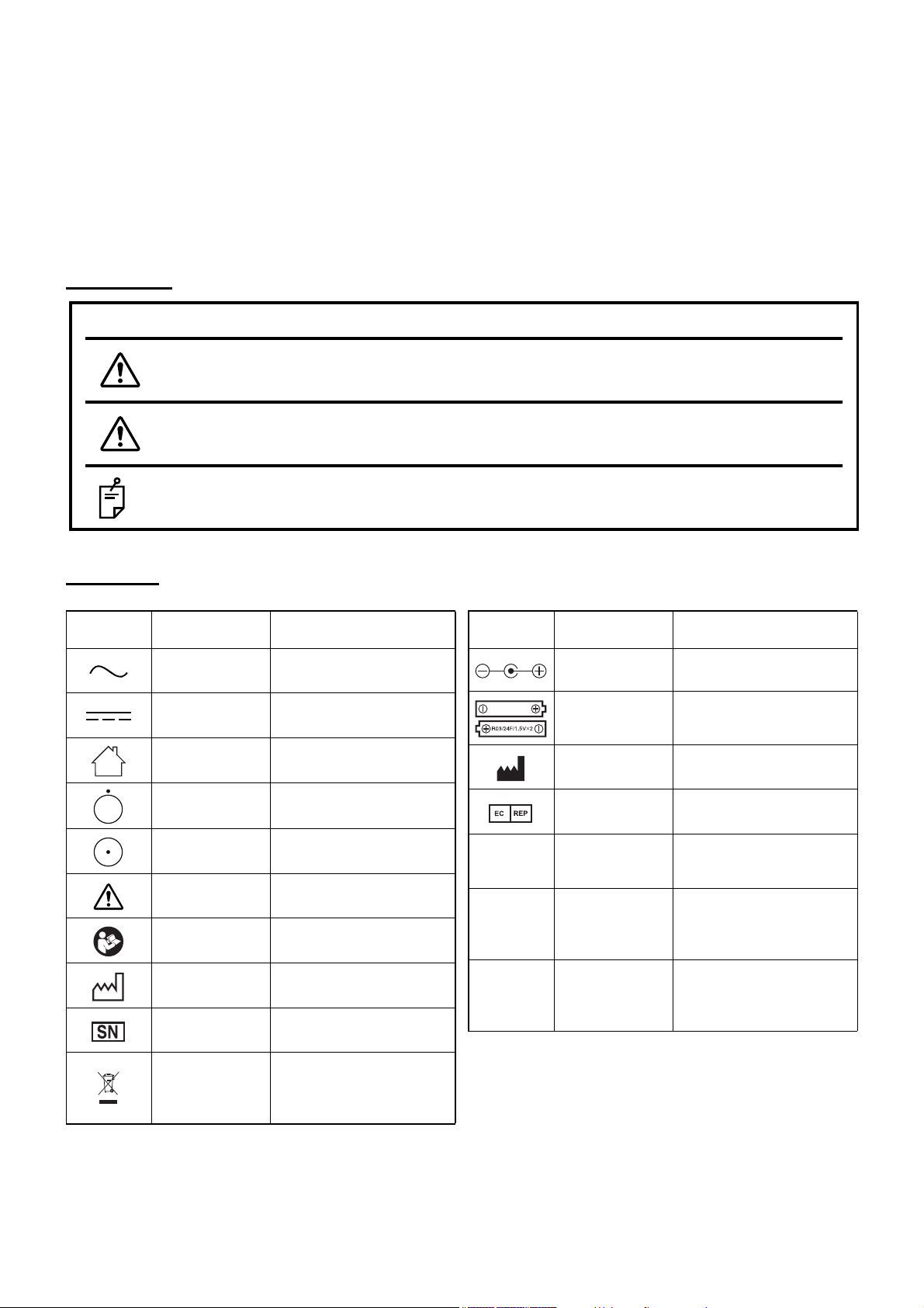
DISPLAYS AND SYMBOLS FOR SAFE USE
Symbol
IEC/ISO
Publication
Description
IEC 60417-5032 Alternating Current
IEC 60417-5031 Direct current
IEC 60417-5957 For indoor use only
IEC 417-5265
“Off” (only for a part of
EQUIPMENT)
IEC 417-5264
“On” (only for a part of
EQUIPMENT)
ISO 7010-W001 General warning sign
ISO 7010-M002
Refer to the instruction manual.
ISO 7000-2497 Date of manufacture
ISO 7000-2498 Serial number
Not applicable
WEEE Directive 2002/96/
EEC
Separate collection is necessary
*
*
Symbol
IEC/ISO
Publication
Description
Not applicable
Polarity
Centre positive symbol
Not applicable The polarity of the batteries
ISO 7000-3082 Manufacturer
ISO 15223-1
Authorised Representative in
the European Community
VGA *
Used to enter the VGA signal. (This is not used when
using the product.)
DVI *
Used to enter the DVI signal.
(The image cable, which is
an accessory, is connected
to this.)
POWER *
Used to connect the AC
adapter. (The AC adapter,
which is an accessory, is
connected to this.)
To encourage safe and proper use and to prevent danger to the operator and others or potential damage
to property, important cautionary messages are placed on the instrument body and inserted in the instruction manual.
We suggest that everyone using the instrument understands the meaning of the following displays, icons
and text before reading the "GENERAL SAFETY INFORMATION" and observes all listed instructions.
DISPLAYS
Display Meaning
Indicates a potentially hazardous situation which, if not avoided,
WARNINGS
CAUTIONS
NOTES
could result in death or serious injury.
Indicates a potentially hazardous situation which, if not avoided, may
result in minor or moderate injury.
Useful functions to know. Paying attention to these will prevent the
problems noted.
SYMBOL
*: for USA and Canada
8
Page 11
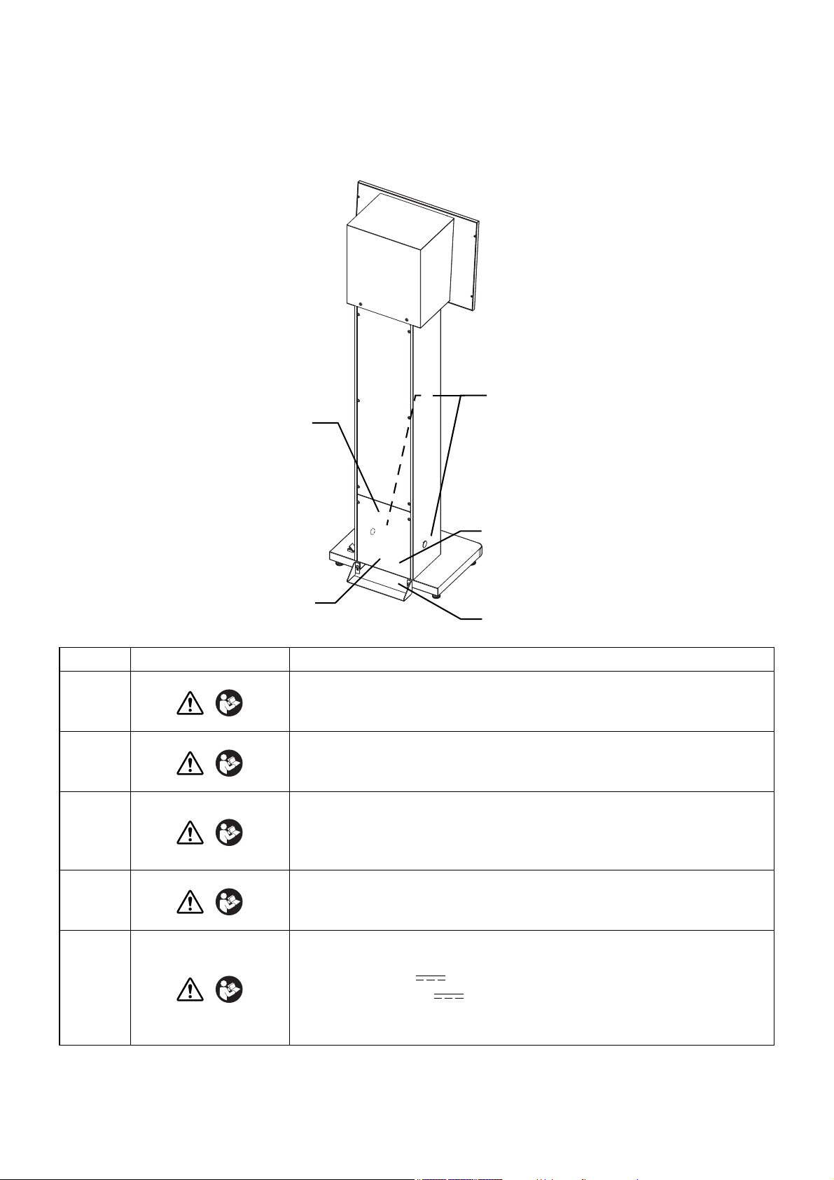
POSITIONS OF WARNING AND CAUTION INDICATIONS
1
3
2
4
5
To ensure safety, the machine provides warning displays.
Use the instrument correctly by observing the display instructions. If any of the following display labels are
missing, contact your TOPCON dealer or your local Topcon office listed on the back cover of this manual.
No. Label Meaning
WARNING
1
2
3
4
5
* Do not connect any equipment to these connections, other than what is listed in the standard compo-
nents table on page 10.
To avoid injury caused by electric shock, do not open the cover.
Ask your dealer for service.
WARNING
Do not the touch the terminal while using the AC adapter.
Doing this may cause injury.
CAUTION
Only install the maintenance cap when cleaning the instrument. If
you do not follow this, the chart may not be displayed correctly and
cause an incorrect test result.
CAUTION
Install the support metal fixture. If you fail to install this, the instrument may fall and injure someone.
Use an AC adapter of the following rating for this instrument.
100V: 12V 2.5A ( )
220-240V: 12V 5A ( )
If you use an adapter which is outside of the above rating, the instrument may be damaged.
CAUTION
9
Page 12

BEFORE USE
STANDARD COMPONENTS
The table below shows the standard components. Make sure that you have all of the components.
The numerical value in ( ) shows the quantity. If one of the standard components is not included in the
package, contact your dealer or your local TOPCON office (listed on the back cover).
User manual /
Power cord (1) AC adapter (1) *
Instruction manual (1)
USER MANUAL
MIRROR CHART
MC-4S
Dust cover (1) Alignment emitter (1) Dry battery (2)
Image cable (1)
* BPM030S12F04 (for USA and Canada)
JMW160KA1200F09 (for outside the USA and Canada)
10
BEFORE USE
Page 13

NOMENCLATURE
2
3
1
4
123
4
CAUTIONS
Front surface
To avoid electric shock, do not touch the external connection terminal
and the patient at the same time.
Chart window: The patient watches the chart through this window.
Power switch/Pilot lamp: The pilot lamp indicates the power status of the instrument. The pilot
lamp is lit in orange when the instrument is plugged into the outlet.
When the power switch is turned ON, this lamp is lit in green and the
instrument can receive the image signal.
Maintenance cap: Use this in maintenance.
Sensor detector unit: This unit receives the signal from the alignment emitter to adjust the
eye position.
11
NOMENCLATURE
Page 14

Lower rear surface
8
5
9
6
10
7
56789
10
Magnet
Battery cover
Light emitting unit
Switch
Cover
NOTES
Analog VGA connector: Usually this is not used.
DVI connector: Used to connect with the external devices (CV-5000 only). Ask the
AC adapter jack: Used to connect the AC adapter.
Support metal fixture: This reinforces the instrument's stability.
Screw for support metal fixture:These affix the support metal fixture onto the instrument.
Adjuster: Used to adjust the inclination when installing the instrument.
Cover is attached to the analog VGA connector. Don't use this connector.
service personnel to connect the instrument with the external
devices.
NOMENCLATURE OF ALIGNMENT EMITTER
12
NOMENCLATURE
Page 15
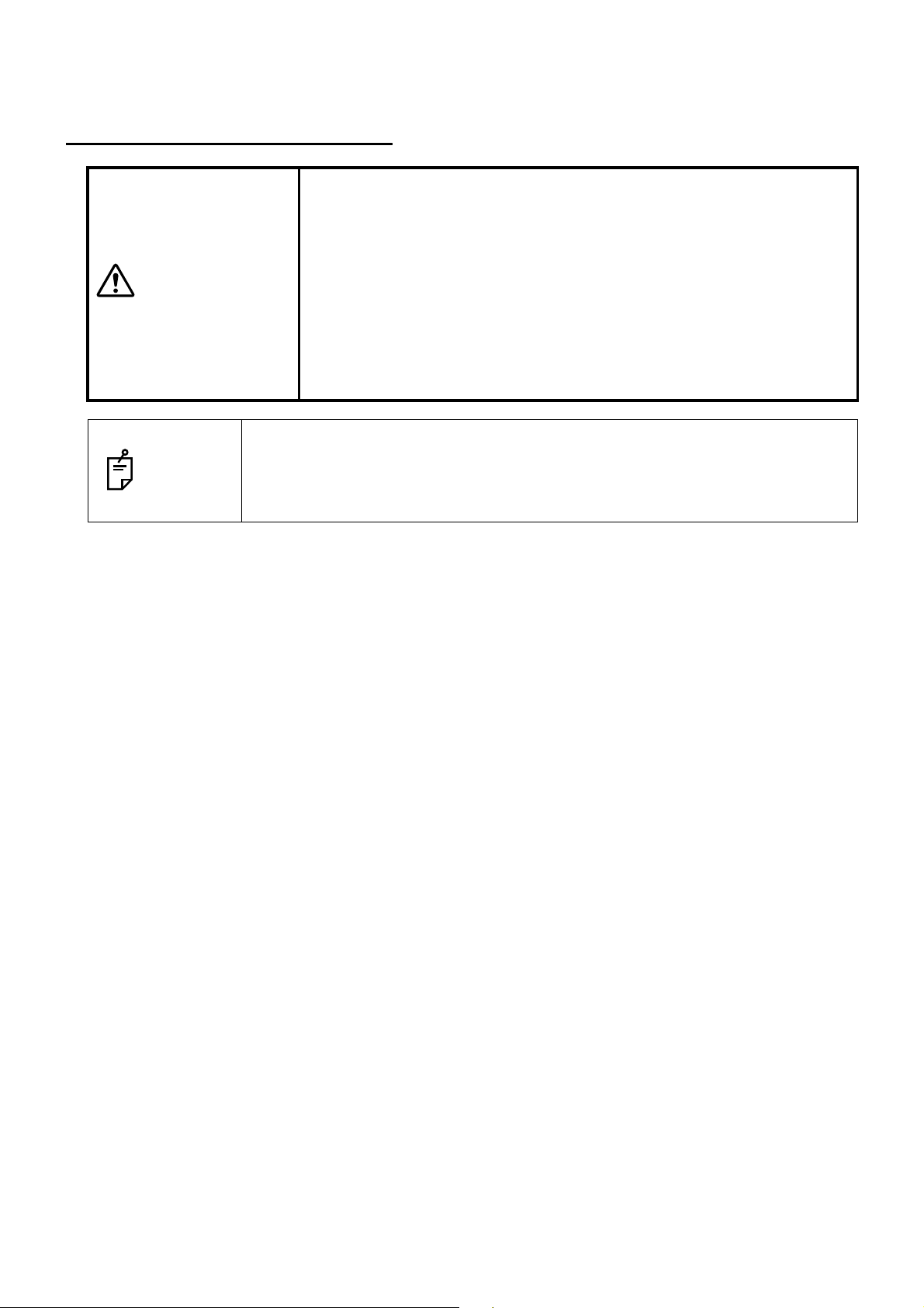
PREPARATION BEFORE USE
INSTALLING THE INSTRUMENT
• Be careful not to damage the chart window or stain it with fingerprints,
dust or other contaminants.
The reliability of the measurement result may be lowered.
CAUTIONS
On the chart window, there is sometimes noticeably unevenness on the back-
NOTES
ground due to interfering light. To prevent sunlight or interfering light from coming in contact with the chart window directly, change the installation location or
the direction of the instrument.
• Tighten the screws for the support metal fixture securely so they cannot be loosened. If the screw becomes loosened, the instrument may
fall and cause damage and/or injury.
• To remove the support metal fixture, ask your service personnel. If the
instrument is not installed along a wall, it may fall and cause injury.
13
PREPARATION BEFORE USE
Page 16
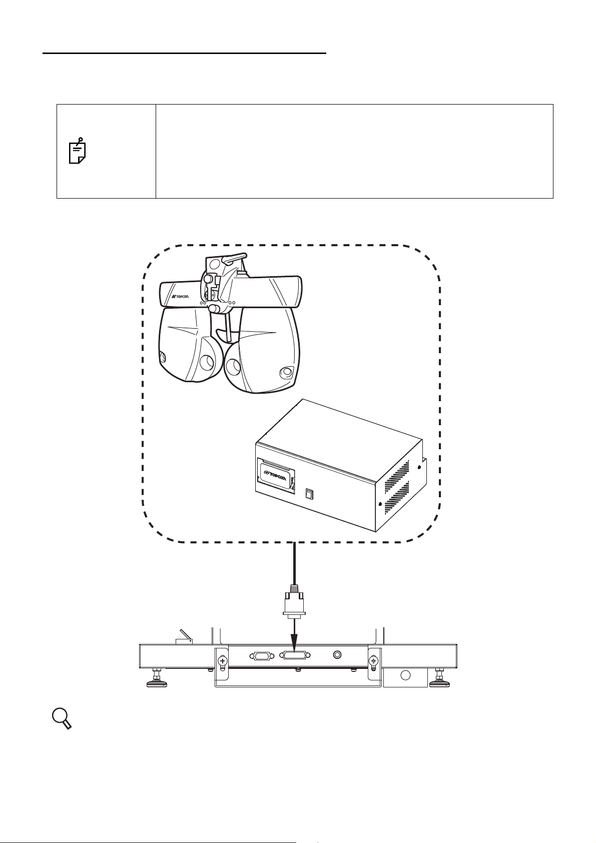
CONNECTING TO COMPU-VISION CV-5000
CV system
MC-4S
This instrument is connected to the CV system and is used as a visual acuity chart.
As shown below, connect the image cable to the DVI connector of this instrument.
This instrument can only be connected to the following devices: CV POWER
SUPPLY UNIT WITH BUILT-IN PERSONAL COMPUTER or the personal com-
NOTES
puter connected to the CV POWER SUPPLY UNIT WITH EXTERNAL PERSONAL COMPUTER. This instrument cannot be connected to the CV power
supply unit and the personal computer connected with the CV power supply
unit.
CV-5000
Refer to the CV-5000 user manual for the connection method for the CV system.
14
PREPARATION BEFORE USE
Page 17
CONNECTING THE POWER CORD
• To avoid fire and electric shock in case of leakage, be sure to use a
WARNINGS
grounded outlet. Do not connect to outlets that are not grounded.
• To avoid electric shock, use only the attached AC adapter.
CAUTIONS
To avoid electric shock, do not handle the plugs with wet fingers.
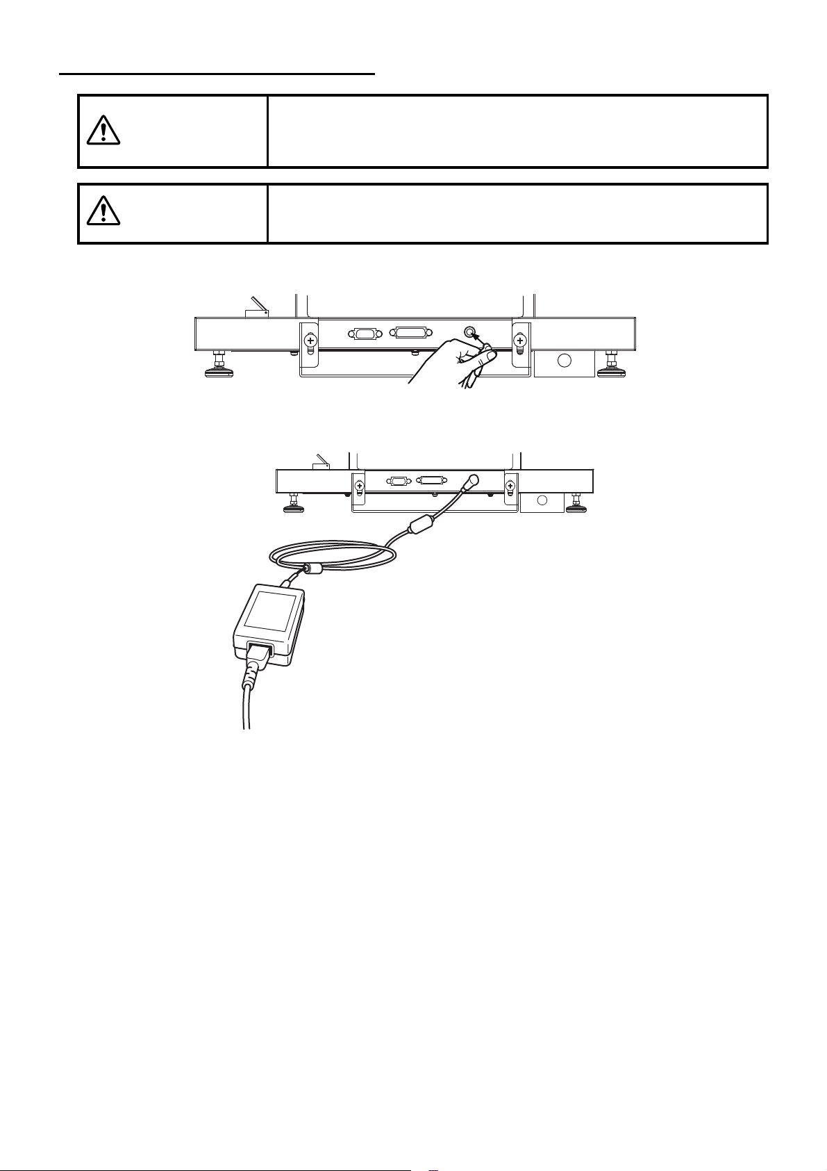
1 Connect the AC adapter to the AC adapter jack on the lower rear surface.
2 Connect the power cord to the AC adapter.
3 Insert the power cord plug into the 3-plug AC outlet with proper grounding.
PREPARATION BEFORE USE
15
Page 18
PILOT LAMP STATUS
The pilot lamp color in each instrument status is shown below.
(1) OFF: AC adapter; Not connected.
Power switch; ON/OFF
(2) Lit in orange: AC adapter; Connected.
Power switch; OFF
(3) Lit in green: AC adapter; Connected.
Power switch; ON
REGISTERING THE VISUAL ACUITY CHART
Operate this instrument through the CV system. This chapter will explain the setting procedure of the
visual acuity chart that is necessary to use this instrument.
1 Turn on this instrument and the power supply unit.
* When operating through a personal computer:
When using this instrument by connecting to a personal computer, it is necessary to display
the desktop on the screen before starting the CV software. Set “Resolution: 640 x 480, 32bit color (Screen refresh rate: 70Hz or more)” for the MC-4S monitor and connect it as the
sub monitor in advance.
Turn on this instrument, the power supply unit and the personal computer to start the CV
software.
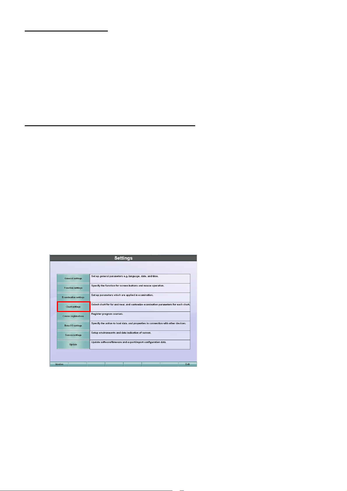
2 While pressing the [Shift] switch on KB-50S, press the [Menu] switch.
The "Settings" menu is displayed.
16
PREPARATION BEFORE USE
Page 19
3 Touch the [Chart settings] button.
The menu to select the chart that should be connected is displayed.
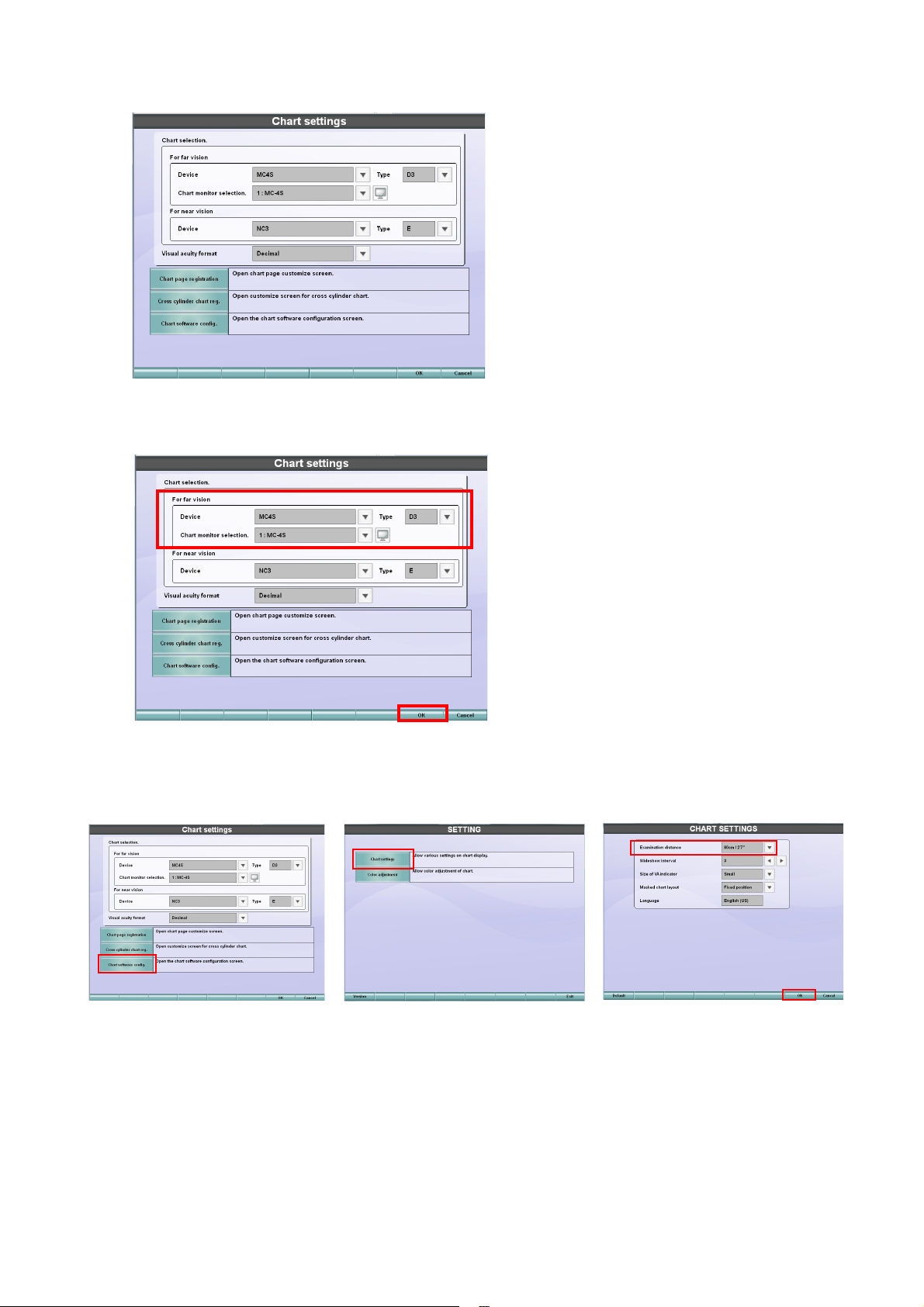
4 Set "MC-4S" for "Device" of "For far vision" and then select a type from "Type". Then, select
"MC-4S" for "Chart monitor selection".
5 Touch the [Chart software config.] button and then the [Chart settings] button. The "CHART
SETTINGS" screen appears. Set [Examination distance] according to the real test distance.
Touch the [OK] button and then the [Exit] button. The "Chart settings" screen appears again.
6 Touch the [OK] button and then the [Exit] button to save the setting and finish the procedure.
17
PREPARATION BEFORE USE
Page 20
SETTING THE INSTALLING DISTANCE
• To avoid electric shock, when setting the installing distance do not
make any contact with the patient and the sensor detector unit at the
CAUTIONS
same time.
• Before setting the installing distance, make sure that the power switch
of the instrument is OFF. If it is ON, you may receive an electric
shock.
NOTES
You can change the installing distance to 60cm, 80cm, 95cm, 1m and 1.5m*.
* Only when selecting the H1 type.
According to the installing distance, it is necessary to change the DIP switch of the instrument.
To change the installing distance setting, ask your service personnel.
1 To perform setting for the instrument, open the cover at the rear of the sensor detector unit.
NOTES
Installing distance
60cm OFF OFF OFF
80cm OFF ON OFF
95cm, 1m, 1.5m OFF OFF ON
To change the setting of the instrument, ask your service personnel.
Instrument
SW01-1 SW01-2 SW01-3
*The installing distance is set to 80cm as the default when shipped.
18
PREPARATION BEFORE USE
Page 21
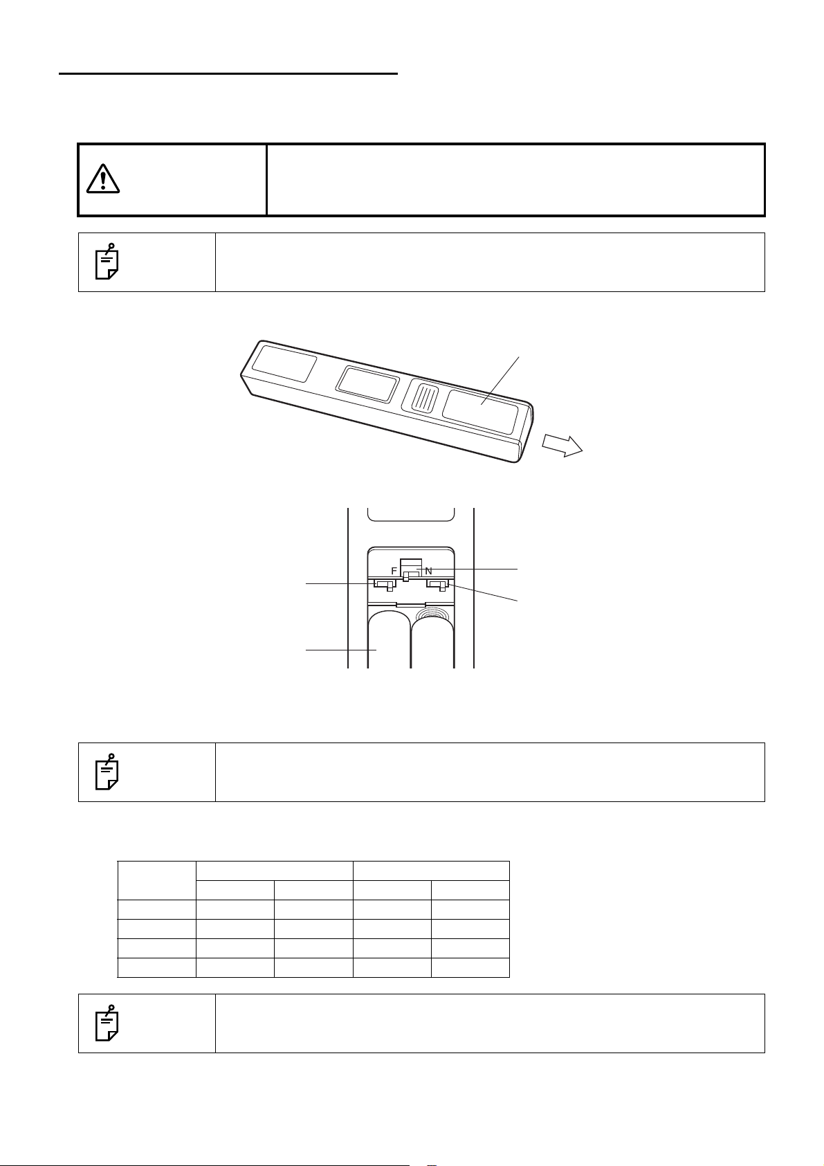
SETTING THE ALIGNMENT EMITTER
Battery cover
Battery box
Slide switch S1
Left: H
Right: L
Slide switch S3
Slide switch S2
Left: H
Right: L
When installing two or more instruments in neighboring areas, it is necessary to set the channels of the
instruments and controllers in order to prevent interference. (It is possible to install up to four instruments.)
To avoid electric shock, when changing the setting of the alignment
CAUTIONS
emitter do not make any contact with the patient and alignment emitter
at the same time.
NOTES
To change the setting of the alignment emitter, ask your service personnel.
1 Remove the battery cover from the alignment emitter.
2 Change the slide switches inside the battery box according to the channel table.
3 Attach the battery cover.
4 To perform the setting for the instrument, open the cover at the rear of the sensor detector unit.
NOTES
Channel table
Setting of alignment emitter and instrument
NOTES
To change the setting of the instrument, ask your service personnel.
Channel
1HHOFFOFF
2LHONOFF
3HLOFFON
4 L L ON ON
Alignment emitter Instrument
S1 S2 SW02-1 SW02-2
"Channel 1" is set as the default when shipped.
19
PREPARATION BEFORE USE
Page 22
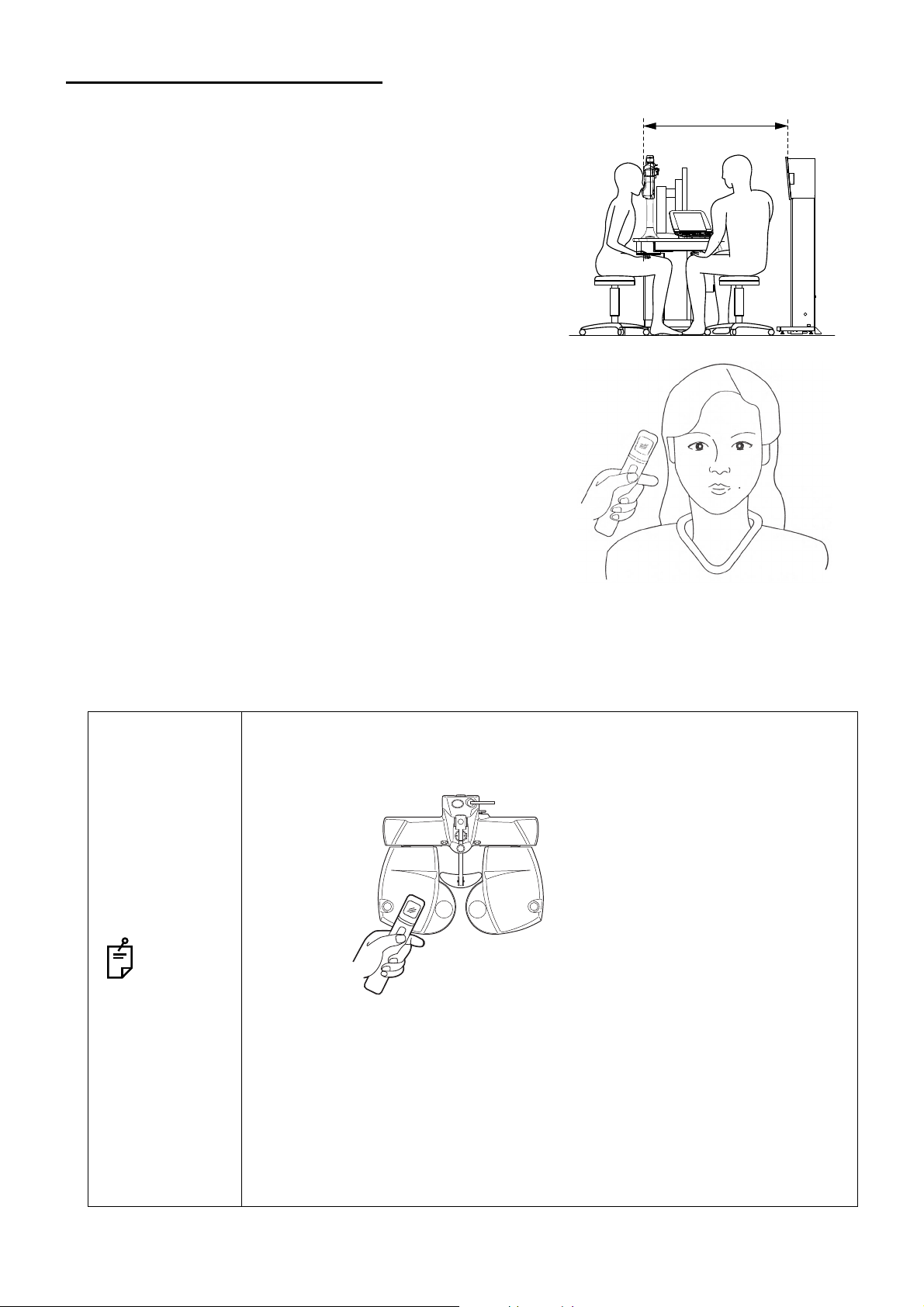
HOW TO ADJUST ALIGNMENT
Place the alignment emitter beside
the eye and adjust the height.
Place the alignment emitter
beside the examination window
and adjust the height.
1 Set 80cm (refer to Note 1) as the distance from the
instrument’s front surface to the patient’s eye. Then,
ask the patient to sit down on the chair.
Note 1: The installing distance can be selected from
60cm, 80cm, 95cm, 1m and 1.5m*.
* Only when selecting the H1 type.
2 Place the alignment emitter beside the right eye of the
patient and press its switch.
80cm
3 Adjust the chart indication position to the optimum within the range of 150mm at the right and left
positions and 200mm in the upper and lower positions against the front of the chart window.
• When the patient watches the chart through the TOPCON CV-5000 or other
instruments, press the alignment emitter switch beside the examination window.
NOTES
• If the alignment emitter is placed too far away in the back-and-forth direction,
sometimes the height is not adjusted correctly though it is beside the eye or
examination window.
• When using the alignment emitter, let it face the sensor detector unit of the
MC-4S.
• If the chart window is in the sunlight or if there is a window behind the patient,
the instrument may operate incorrectly or its buzzer may sound continuously
to stop its operation. Change the installation location or close the curtain or
blind.
20
PREPARATION BEFORE USE
Page 23
INDICATION OF CHART
The MC-4S has the functions particular to the image indication type. This user manual will explain the
chart functions that are unique to the MC-4S. For a general indication of charts, refer to the Compu-Vision
CV-5000 user manual.
• The Compu-Vision CV-5000 user manual describes the tests when the MC-4S
is used.
• When the instrument is set to indicate the visual acuity, it is indicated at the
NOTES
TEST CHART LIST
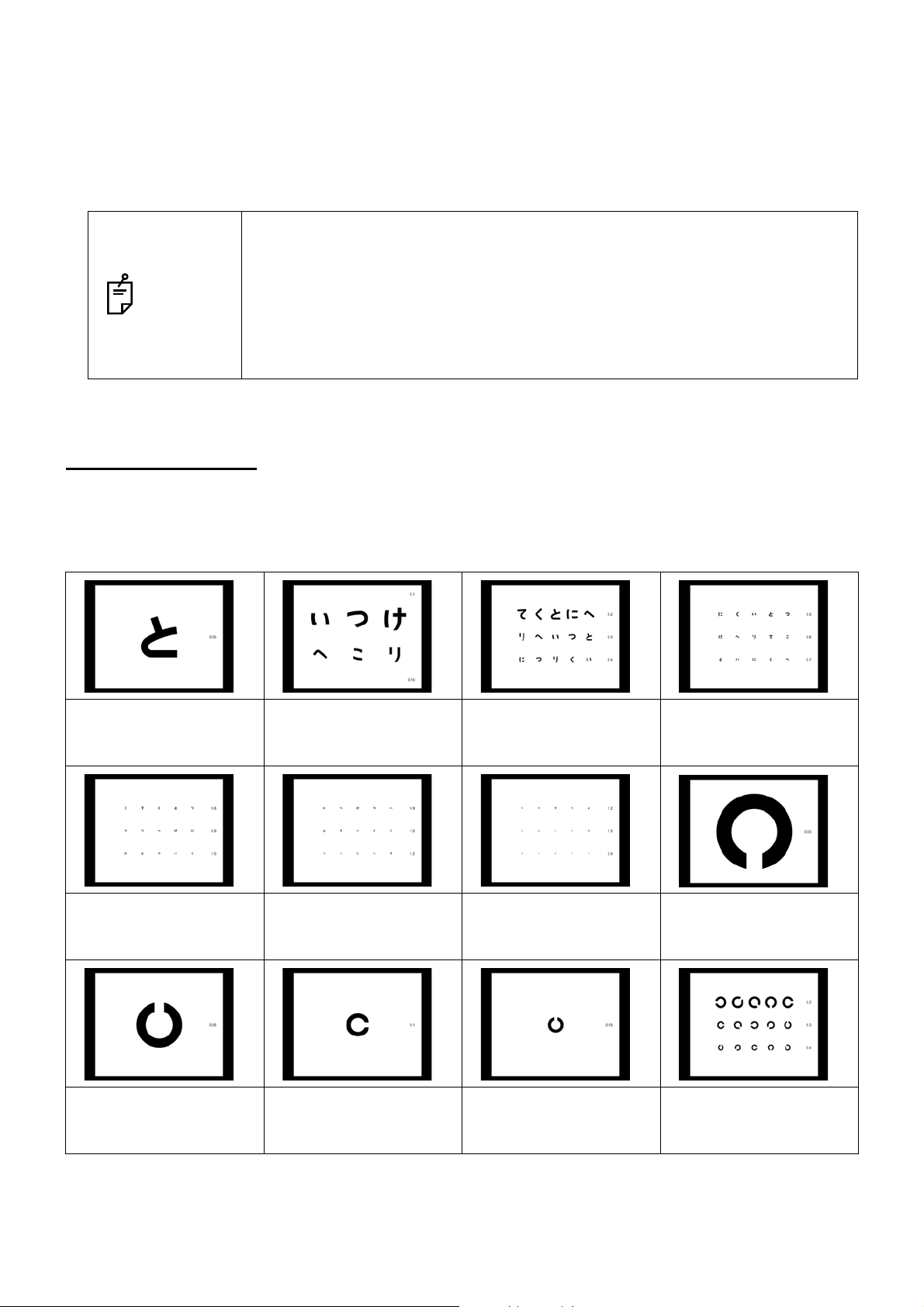
The MC-4S can indicate three types of charts (D type, F type and H1 type).
right side of the chart.
When a large chart is selected, the visual acuity is indicated at the upper or
lower right. Sometimes, even if the system is set to indicate the visual acuity
in large size, it is forcedly indicated in small size.
• D type
Hiragana chart:
Visual acuity 0.05
Hiragana chart:
Visual acuity 0.8, 0.9
and 1.0
Hiragana chart:
Visual acuity 0.1 and
0.15
Hiragana chart:
Visual acuity 0.9, 1.0
and 1.2
Hiragana chart:
Visual acuity 0.2, 0.3
and 0.4
Hiragana chart:
Visual acuity 1.2, 1.5
and 2.0
Hiragana chart:
Visual acuity 0.5, 0.6
and 0.7
Landolt ring chart:
Visual acuity 0.03
Landolt ring chart:
Visual acuity 0.05
Landolt ring chart:
Visual acuity 0.1
Landolt ring chart:
Visual acuity 0.15
Landolt ring chart:
Visual acuity 0.2, 0.3
and 0.4
21
INDICATION OF CHART
Page 24

Landolt ring chart:
Visual acuity 0.5, 0.6
and 0.7
Landolt screening chart ETDRS chart (1) ETDRS chart (2) Illustration chart
Landolt ring chart:
Visual acuity 0.8, 0.9
and 1.0
Landolt ring chart:
Visual acuity 1.2, 1.5
and 2.0
Hiragana screening
chart
RG chart RG binocular balance
chart
Reticle heterophoria
chart (black background)
Fixation target chart Cyclophoria chart
Cross chart with fixation
target (white background)
(white background)
Binocular balance
(polarization) chart
Cross chart with fixation
target (black background)
Cyclophoria chart
(black background)
Reticle heterophoria
chart (white background)
Cross ring chart
One vertical line character chart
One horizontal line
character chart
22
INDICATION OF CHART
Aniseikonia chart Precise stereoscopic
vision chart
Depth perception test
chart
Page 25

Worth 4 Dots chart Cross cylinder chart (1) Cross cylinder chart (2) Cross cylinder chart (3)
Astigmatism chart (1) Astigmatism chart (2) Astigmatism chart (3)
• F type
Letter E chart:
Visual acuity 0.03
Letter E chart:
Visual acuity 0.5, 0.6 and 0.7
Landolt ring chart:
Visual acuity 0.1 and 0.16
Letter E chart:
Visual acuity 0.05
Letter E chart:
Visual acuity 0.8, 0.9 and 1.0
Landolt ring chart:
Visual acuity 0.2, 0.3 and 0.4
Letter E chart:
Visual acuity 0.1 and 0.16
Letter E chart:
Visual acuity 1.2, 1.5 and 2.0
Landolt ring chart:
Visual acuity 0.5, 0.6 and 0.7
Letter E chart:
Visual acuity 0.2, 0.3 and 0.4
Landolt ring chart:
Visual acuity 0.05
Landolt ring chart:
Visual acuity 0.8, 0.9 and 1.0
Landolt ring chart:
Visual acuity 1.2, 1.5 and 2.0
Numeral chart:
Visual acuity 0.1 and 0.2
Numeral chart:
Visual acuity 0.3, 0.4 and 0.5
Numeral chart:
Visual acuity 0.6, 0.7 and 0.8
23
INDICATION OF CHART
Page 26

Numeral chart:
Visual acuity 1.0, 1.2
and 1.5
ETDRS chart (1) ETDRS chart (2) RG chart Binocular balance
Chart for children:
Visual acuity 0.2 and
0.3
Chart for children:
Visual acuity 0.4, 0.5
and 0.6
Chart for children:
Visual acuity 0.7, 0.8
and 1.0
(polarization) chart
Reticle heterophoria
chart (white background)
Cross chart with fixation
target (white background)
Stereoscopic vision
chart
Reticle heterophoria
chart (black background)
Cross chart with fixation
target (black background)
Worth 4 Dots chart Cross cylinder chart (1) Cross cylinder chart (2)
Cross ring chart Fixation target chart
Aniseikonia chart (vertical)
Aniseikonia chart (horizontal)
Cross cylinder chart (3) Astigmatism chart (1) Astigmatism chart (2) Astigmatism chart (3)
24
INDICATION OF CHART
Page 27

• H1 type
Alphabet chart:
Visual acuity 400
Alphabet chart:
Visual acuity 40, 30 and
25
Alphabet and numeral
chart: Visual acuity 25,
20 and 15
Alphabet chart:
Visual acuity 200 and 150
Alphabet chart:
Visual acuity 30,25 and
20
Letter E chart:
Visual acuity 600
Alphabet chart:
Visual acuity 100 and 80
Alphabet chart:
Visual acuity 20, 15 and
10
Letter E chart:
Visual acuity 400
Alphabet chart:
Visual acuity 70, 60 and 50
Alphabet chart:
Visual acuity 20
Letter E chart:
Visual acuity 200
Letter E chart:
Visual acuity 150
Letter E chart:
Visual acuity 30,25 and 20
Numeral chart:
Visual acuity 70, 60 and 50
Letter E chart:
Visual acuity 100 and 80
Letter E chart:
Visual acuity 20, 15 and 10
Numeral chart:
Visual acuity 40, 30 and 25
Letter E chart:
Visual acuity 70, 60 and 50
Numeral chart:
Visual acuity 200 and 150
Numeral chart:
Visual acuity 30,25 and 20
Letter E chart:
Visual acuity 40, 30 and 25
Numeral chart:
Visual acuity 100 and 80
Numeral chart:
Visual acuity 20, 15 and 10
25
INDICATION OF CHART
Page 28
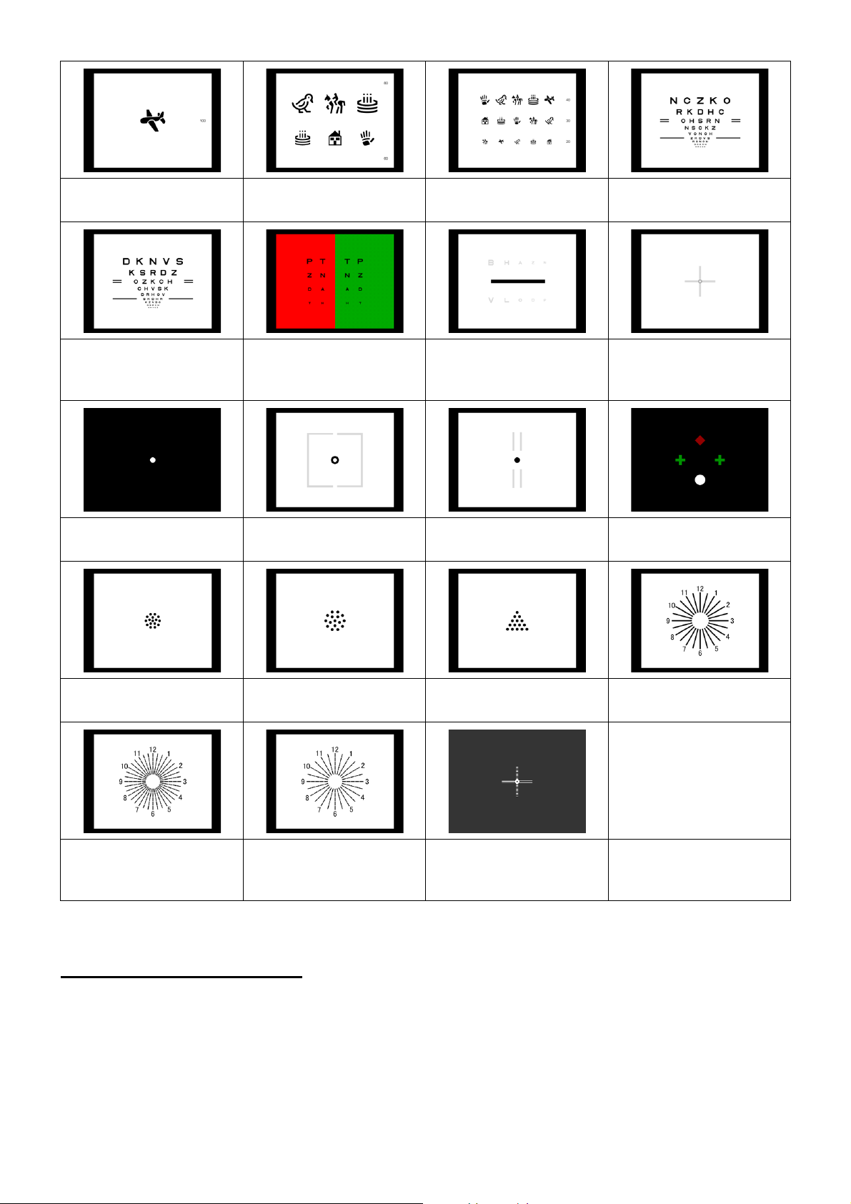
Chart for children:
Visual acuity 100
Chart for children:
Visual acuity 80 and 60
Chart for children:
acuity 40, 30 and 20
Visual
ETDRS chart (1)
ETDRS chart (2) RG chart Binocular balance
(polarization) chart
Fixation target chart Aniseikonia chart Stereoscopic vision
chart
Cross cylinder chart (1) Cross cylinder chart (2) Cross cylinder chart (3) Astigmatism chart (1)
Cross chart with fixation
target (white background)
Worth 4 Dots chart
Astigmatism chart (2) Astigmatism chart (3) Cross chart with fixation
target (black background)
OPERATION AFTER USE
1 Turn off the power switch.
2 Unplug the power cable from a 3-pin AC inlet with grounding.
26
INDICATION OF CHART
Page 29

CHART FUNCTIONS UNIQUE TO THE MC-4S
BLACK-AND-WHITE REVERSING FUNCTION
The MC-4S has the ability to change the chart indicating black characters with white background to the
one indicating white characters with black background in the visual acuity measurement.
Relevant chart
This function is applied to the visual acuity charts except the screening chart.
An example of the test chart icon displayed on the chart page of the KB-50S:
Usable chart
Reversing the black-and-white display condition
1 Select the visual acuity chart which can be reversed from the chart page.
2 Press the [Shift] key on the KB-50S and touch the [Reverse] button among the function buttons
at the bottom of the screen.
3 On the MC-4S, the chart is displayed in the reversed black-and-white condition.
At the same time, the chart is also displayed in the reversed condition on the chart check display
area of the KB-50S.
27
CHART FUNCTIONS UNIQUE TO THE MC-4S
Page 30

• To reverse the black-and-white condition through the mouse/personal computer, click the button displayed on the test screen of Step 2.
• The black-and-white reverse mode is kept while the following operations are
NOTES
Canceling the reversed black-and-white display condition
being executed.
• Changing to any other visual acuity chart applicable to this reverse mode
• Setting and moving the vertical mask, horizontal mask and character mask
• Executing the random mode
1 Press the [Shift] key on the KB-50S and touch the [Reverse] button among the function buttons
at the bottom of the screen.
2 The reversed black-and-white condition of the chart indicated on the MC-4S is canceled.
At the same time, the reversed condition of the chart is also canceled on the chart check display
area of the KB-50S.
• To cancel the reversed black-and-white condition through the mouse/personal
computer, click the button displayed on the test screen of Step 2.
• The black-and-white reverse mode is also canceled by the following opera-
NOTES
tions.
• Changing to the chart which is not applicable to this reverse mode
• Setting the RG mask
• Setting the contrast mode
28
CHART FUNCTIONS UNIQUE TO THE MC-4S
Page 31

CHARACTER CONTRAST CHANGING FUNCTION
In the MC-4S, the character contrast of the chart can be changed and displayed for visual acuity measurement.
There are two display methods. "Single rate character contrast mode" changes the character contrast of
the whole chart uniformly. "Plural rate character contrast mode" changes the contrast of each column on
the chart.
Single rate character contrast mode
In "Single rate character contrast" mode, the character contrast on the chart can be changed in seven
steps, 2.5%, 5%, 10%, 12.5%, 25%, 50%, and 100%.
Relevant chart
This function is applied to all the visual acuity charts except the screening chart.
An example of the test chart icon displayed on the chart page of the KB-50S:
Usable chart
Setting "Single rate character contrast"
1 Select the visual acuity chart applicable to the "Single rate character contrast" function from the
chart page.
2 Touch the [Contrast] button among the function buttons at the bottom of the screen on the KB-
50S to display the contrast setting menu.
29
CHART FUNCTIONS UNIQUE TO THE MC-4S
Page 32

3 Touch the button of the desired contrast from the contrast setting menu. The chart indicated on
the MC-4S is displayed with the selected contrast as shown below.
• When operating the CV system through a mouse/personal computer, you can
change the contrast with the same procedure.
NOTES
• When changing the chart to another that is applicable to this mode, the "Single rate character contrast" mode is kept.
• While the "Single rate character contrast" mode is being executed, you cannot
set the vertical, horizontal, character and RG masks.
Input of contrast visual acuity in the single rate character contrast mode
1 Input the visual acuity value. For inputting the visual acuity, refer to the COMPU-VISION CV-
5000 USER MANUAL.
2 The visual acuity value with the contrast value, which is being displayed, is recorded.
30
CHART FUNCTIONS UNIQUE TO THE MC-4S
Page 33

Canceling "Single rate character contrast"
1 Touch the [Contrast] button among the function buttons at the bottom of the screen on the KB-
50S to display the contrast setting menu.
2 Touch the [Exit] button on the contrast selection menu, and the "Single rate character contrast"
mode is canceled.
• When operating the CV system through a mouse/personal computer, you can
NOTES
cancel the contrast with the same procedure.
• When changing to a chart that is not applicable to this mode, the "Single rate
character contrast" mode is also canceled.
Plural rate character contrast mode
In the "Plural rate character contrast" mode, the contrast conditions of the five stages, 25%, 12.5%,
10%, 5% and 2.5%, can be displayed on one chart at a time.
Relevant chart
This function is applied to a visual acuity chart having 3 lines and 5 columns.
An example of the test chart icon displayed on the chart page of the KB-50S:
Usable chart
Unusable chart
31
CHART FUNCTIONS UNIQUE TO THE MC-4S
Page 34

Setting "Plural rate character contrast"
1 Select the visual acuity chart applicable to the "Plural rate character contrast" function.
2 Touch the [Contrast] button among the function buttons at the bottom of the screen on the KB-
50S to display the contrast setting menu.
3 Touch the [Plural rate] button in the contrast setting menu. As shown below, on the MC-4S, the
chart is displayed under the condition that the columns are different in contrast by stages, 25%,
12.5%, 10%, 5% and 2.5% from the leftmost.
• When operating the CV system through a mouse/personal computer, you can
change the contrast with the same procedure.
NOTES
• When changing the chart to another that is applicable to this mode, the "Plural
rate character contrast" mode is kept.
• While the "Plural rate character contrast" mode is being executed, you cannot
set the vertical, horizontal, character and RG masks.
32
CHART FUNCTIONS UNIQUE TO THE MC-4S
Page 35

Input of contrast visual acuity in the plural rate character contrast mode
1 Input the visual acuity value. For inputting the visual acuity, refer to the COMPU-VISION CV-
5000 USER MANUAL.
2 The dialog box to select a contrast value is displayed. Touch the desired contrast value.
3 The visual acuity with the touched contrast value is recorded.
Canceling "Plural rate character contrast"
1 Touch the [Contrast] button among the function buttons at the bottom of the screen on the KB-
50S to display the contrast setting menu.
2 Touch the [Exit] button on the contrast selection menu, and the "plural rate character contrast"
mode is canceled.
• When operating the CV system through a mouse/personal computer, you can
NOTES
cancel the contrast with the same procedure.
• When changing to a chart that is not applicable to this mode, the "Plural rate
character contrast" mode is also canceled.
33
CHART FUNCTIONS UNIQUE TO THE MC-4S
Page 36

ACTIVE CHART
In the MC-4S, it is possible to use "Active chart" for testing/checking by making use of the characteristics
of the built-in liquid crystal visual acuity chart.
Prism simulation function
With this function, you can move the target indicated to the right/left eyes in the phoria test. This function is useful to explain the eye condition to the patient or check the patient's eye after the test.
Relevant chart
The following charts are applicable to this function:
Executing "Prism simulation"
1 Select the chart applicable to "Prism simulation" from the chart page.
2 Perform the phoria measurement according to normal procedure.
3 Touch the [Simulate] button among the function buttons at the bottom of the screen on the KB-50S.
4 The prism lens, which is set on the measuring head of the CV-5000, is temporarily canceled. As
shown below, the chart is converted so that the targets may be indicated at the right and left eye
target positions and then the chart is displayed on the MC-4S.
The prism measurement value is rounded to the 0.2 prism step value.
Example: Cross chart
Before simulation After simulation
34
CHART FUNCTIONS UNIQUE TO THE MC-4S
Page 37

5 You can change the prism amount by using the dial of the KB-50S.
In the "Simulation" mode, the prism movable range is 6.0
4.4
BD to 4.4BU for vertical prism.
Turn the dial, and the target moves according to "Dial Navigation".
Horizontal phoria
measurement
Vertical phoria
measurement
Example of "Dial Navigation" for cross chart
Turn the dial clockwise, and the vertical line moves left
and the horizontal line moves right.
Turn the dial counterclockwise, and the vertical line
moves right and the horizontal line moves left.
Turn the dial clockwise, and the vertical line moves down
and the horizontal line moves up.
Turn the dial counterclockwise, and the vertical line
moves up and the horizontal line moves down.
6 To finish "Simulation", touch the [Simulate] button again.
The chart of the MC-4S is returned to the display status before executing "Simulation".
The prism lens on the measuring head of the CV-5000 is set according to the current prism
value.
BI to 6.0BO for horizontal prism and,
• When operating through a mouse/personal computer, do not turn the dial but
click the button on the control window. Operate according to "Mouse Navigation".
• The "Simulation" mode cannot be executed in the following case: The preset
prism value before accessing the "Simulation" mode is beyond the prism movable range of the "Simulation" mode.
NOTES
• When executing the "Simulation" mode with the cross ring chart, the prism
movable range is 6.0
BU for vertical prism. The range where the targets are within the chart
4.4
screen is 1.4
tical prism. If you set the prism value exceeding this range, the right eye target moves to the outside of the chart because of the chart shape
characteristics.
• When changing to other charts, the "Simulation" mode is also exited.
BI to 1.4BO for horizontal prism and 1.0BD to 1.0BU for ver-
BI to 6.0BO for horizontal prism and 4.4BD to
Aniseikonia simulation function
By using the aniseikona simulation function, the target size at the left side of the vertical aniseikonia
chart can be changed in stages and, under this changed status, the chart can be displayed.
Relevant chart
The following chart is applicable to this function:
35
CHART FUNCTIONS UNIQUE TO THE MC-4S
Page 38

Executing "Aniseikonia simulation"
1 Select the chart applicable to "Aniseikonia simulation" from the chart page.
2 Touch the [Simulate] button among the function buttons at the bottom of the screen on the KB-50S.
3 The "Simulation" mode starts.
Turn the dial of the KB-50S during the "Simulation" mode, and the square size at the left side is
changed as shown below. Adjust the size so that the patient can see the right and left targets in
the same size.
4 Operate the dial according to "Dial Navigation".
Turn the dial clockwise, and the left target size is decreased by 0.5%
step.
Turn the dial counterclockwise, and the left target size is increased by
0.5% step.
The changeable size range is -10% to 10% with the size rate of the left square against the right
one.
The size during changing is displayed on the function button at the bottom of the screen on the
KB-50S.
36
CHART FUNCTIONS UNIQUE TO THE MC-4S
Page 39

5 To record the result, touch the [Record] button among the function buttons at the bottom of the
screen on the KB-50S.
6 To finish "Simulation", touch the [Simulate] button again.
The chart of the MC-4S is returned to the display status before executing "Simulation".
• When operating through a mouse/personal computer, do not turn the dial but
NOTES
click the button on the control window. Operate according to "Mouse Navigation".
• When changing to other charts, the "Simulation" mode is also exited.
Astigmatism chart rotation function
By using this function, on the astigmatism chart where only one radial line color is deeper than others,
the deeper line can be changed with the dial. To measure the cylinder axis by using the astigmatism
chart, let the patient align the deeper line on the chart with the line whose color is deeper in his/her
vision.
Relevant chart
The following charts are applicable to this function:
37
CHART FUNCTIONS UNIQUE TO THE MC-4S
Page 40

Executing "Astigmatism chart rotation function"
1 Select the chart applicable to the "Astigmatism chart rotation" function from the chart page.
2 Touch the [Rotate] button among the function buttons at the bottom of the screen on the KB-50S.
When the cylinder power and axis are already measured and the lens is already set on the measuring head of the CV-5000, the cylinder axis is rounded to the 5-degree step value and the cylinder power is temporarily set to 0.00D.
3 The chart on the screen of the MC-4S is changed to the following one.
Turn the dial of the KB-50S, and the deeper color line on the astigmatism chart is changed in the
dial turning direction.
Let the patient align the deeper color line on the chart with the line whose color is deeper in his/
her vision.
4 To exit the "Astigmatism chart rotation" mode, touch the [Rotate] button again.
The chart of the MC-4S is returned to the status before executing the "Astigmatism chart rotation"
function.
The cylinder power before executing the "Astigmatism chart rotation" mode is set with the current
cylinder axis on the measuring head of the CV-5000.
• When operating through a mouse/personal computer, do not turn the dial but
click the button on the control window. Operate according to "Mouse Navigation".
NOTES
• While the "Astigmatism chart rotation" mode is being executed in the KB-50S,
the display of "Dial Navigation" is opposite to the real axis value change.
• When changing to other charts, the "Astigmatism chart rotation" mode is also
exited.
38
CHART FUNCTIONS UNIQUE TO THE MC-4S
Page 41

DISPLAY OF STILL IMAGE/MOVIE
It is possible to display still images/movies on the MC-4S. In addition, the 3D still images and movies can
be displayed by making use of the polarization chart characteristics.
Still images and movies are preinstalled.
It is also possible to display the still images and movies prepared by the customer.
Preinstalled contents
When shipped, 20 files of still images, 2 files of movies and 9 files of still images for slideshows for
each of D type, F type and H1 type are provided in the MC-4S.
Still image file
• D type
Chart page
icon
MC-4S Test screen Remarks
Still image is displayed on MC-4S and
the test screen.
Still image is displayed on MC-4S and
the test screen.
Still image is displayed on MC-4S and
the test screen.
Still image is displayed on MC-4S and
the test screen.
Still image is displayed on MC-4S and
the test screen.
39
CHART FUNCTIONS UNIQUE TO THE MC-4S
Page 42

Chart page
icon
MC-4S Test screen Remarks
Still image is displayed on MC-4S and
the test screen.
Still image is displayed on MC-4S and
the test screen.
Still image is displayed on MC-4S and
the test screen.
Still image is displayed on MC-4S and
the test screen.
Still image is displayed on MC-4S and
the test screen.
Still image is displayed on MC-4S and
the test screen.
Still image is displayed on MC-4S and
the test screen.
40
CHART FUNCTIONS UNIQUE TO THE MC-4S
Page 43

Chart page
icon
MC-4S Test screen Remarks
The still image is displayed on the MC4S only.
The still image is displayed on the MC4S only.
This still image is the 3D still image.
Watch this image through the polarized
lens set on the measuring head of the
CV-5000. It will be seen as a stereoscopic vision.
This still image is the 3D still image.
Watch this image through the polarized
lens set on the measuring head of the
CV-5000. It will be seen as a stereoscopic vision.
This still image is the 3D still image.
Watch this image through the polarized
lens set on the measuring head of the
CV-5000. It will be seen as a stereoscopic vision.
This still image is the 3D still image.
Watch this image through the polarized
lens set on the measuring head of the
CV-5000. It will be seen as a stereoscopic vision.
This still image is the 3D still image.
Watch this image through the polarized
lens set on the measuring head of the
CV-5000. It will be seen as a stereoscopic vision.
41
CHART FUNCTIONS UNIQUE TO THE MC-4S
Page 44

Chart page
icon
• F type, H1 type
MC-4S Test screen Remarks
This still image is the 3D still image.
Watch this image through the polarized
lens set on the measuring head of the
CV-5000. It will be seen as a stereoscopic vision.
Chart page
icon
MC-4S Test screen Remarks
Still image is displayed on MC-4S and
the test screen.
Still image is displayed on MC-4S and
the test screen.
Still image is displayed on MC-4S and
the test screen.
Still image is displayed on MC-4S and
the test screen.
42
CHART FUNCTIONS UNIQUE TO THE MC-4S
Still image is displayed on MC-4S and
the test screen.
Still image is displayed on MC-4S and
the test screen.
Page 45

Chart page
icon
MC-4S Test screen Remarks
Still image is displayed on MC-4S and
the test screen.
This still image is the 3D still image.
Watch this image through the polarized
lens set on the measuring head of the
CV-5000. It will be seen as a stereoscopic vision.
This still image is the 3D still image.
Watch this image through the polarized
lens set on the measuring head of the
CV-5000. It will be seen as a stereoscopic vision.
This still image is the 3D still image.
Watch this image through the polarized
lens set on the measuring head of the
CV-5000. It will be seen as a stereoscopic vision.
This still image is the 3D still image.
Watch this image through the polarized
lens set on the measuring head of the
CV-5000. It will be seen as a stereoscopic vision.
This still image is the 3D still image.
Watch this image through the polarized
lens set on the measuring head of the
CV-5000. It will be seen as a stereoscopic vision.
This still image is the 3D still image.
Watch this image through the polarized
lens set on the measuring head of the
CV-5000. It will be seen as a stereoscopic vision.
The still image is displayed on the MC4S only.
43
CHART FUNCTIONS UNIQUE TO THE MC-4S
Page 46

Chart page
Chart page icon (example)
icon
MC-4S Test screen Remarks
The still image is displayed on the MC4S only.
The still image is displayed on the MC4S only.
The still image is displayed on the MC4S only.
The still image is displayed on the MC4S only.
Playback of still images
1 Select an optional still image icon from the chart page.
The still image is played.
The still image is displayed on the MC4S only.
The still image is displayed on the MC4S only.
NOTES
Select any other chart. The playback of the still image is finished and the
selected chart is indicated.
44
CHART FUNCTIONS UNIQUE TO THE MC-4S
Page 47

Movie file
Chart page icon (example)
• D type
Chart page
icon
• F type, H1 type
Chart page
icon
MC-4S Remarks
This movie is the 3D movie.
Watch this movie through the polarized lens set on the measuring head of the CV-5000. It will be seen as a stereoscopic
vision.
This movie shows the landscape photographed from the car
running on a superhighway.
MC-4S Remarks
Playback of movie
1 Select "MOVIE" from the chart page.
The movie is played.
This movie is the 3D movie.
Watch this movie through the polarized lens set on the measuring head of the CV-5000. It will be seen as a stereoscopic
vision.
This movie is the animation showing the scene "Traveling on
the road at night".
NOTES
Select any other chart. The playback of the movie is finished and the selected
chart is indicated.
45
CHART FUNCTIONS UNIQUE TO THE MC-4S
Page 48

Still image file for slideshow
Chart page icon
• D type, F type, H1 type
Chart page
icon
MC-4S Remarks
The images are displayed on the MC4S in the order
shown.
The still image display time can be
changed in the setting screen.
Playback of slideshow
1 Select "Slideshow" from the chart page.
The image slideshow is played.
NOTES
Select any other chart. "Slideshow" is canceled and the selected chart is indicated on the instrument.
46
CHART FUNCTIONS UNIQUE TO THE MC-4S
Page 49

REGISTRATION (USER CUSTOMIZE) AND DISPLAY/PLAYBACK OF STILL IMAGES/MOVIES
User customizable contents
In the MC-4S, it is possible to display/play back the still images/movies prepared by the customer by
saving them in the USB memory and connecting it with the CV-5000 system.
NOTES
It is necessary to connect the USB memory to the USB port of the CV-5000 system before starting this system.
Contents that can be added:
The contents that can be added by the customer are shown below.
2D still image
It is possible to display the photos taken by a digital camera and an illustration made by the customer.
Access this still image from the KB-50S and display it optionally.
3D still image
Register one image for each of the right and left eyes. It is possible to compound these images
so that they may be displayed as a 3D image on the MC-4S.
To display the stereoscopic image, prepare the still images for the right and left eyes with a little
parallax between them. Access this still image from the KB-50S and display it optionally.
Still image to be displayed on the test screen
It is possible to relate the photos taken by a digital camera and an illustration made by the customer with the 2D or 3D still images and display them on the test screen in a link operation.
For instance, it is possible to display a far image on the MC-4S and, on the test screen, display a
nearby image.
Movie
It is possible to display the image taken by the video camera.
Still image for slideshow
The photos taken by a digital camera and an illustration made by the customer can be displayed
as a slideshow.
CHART FUNCTIONS UNIQUE TO THE MC-4S
47
Page 50
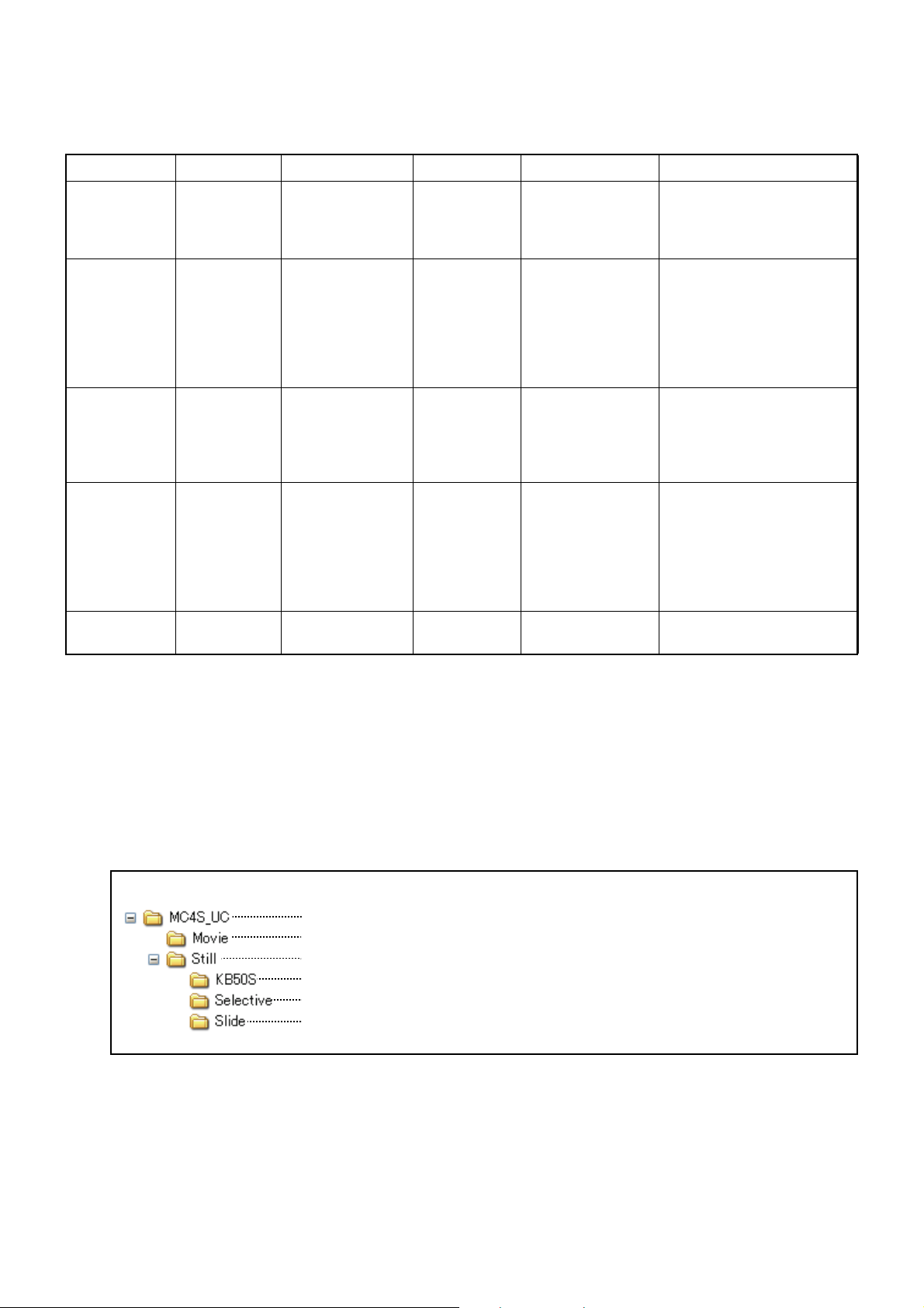
File format
USB memory
This folder contains all of the user customizable contents.
This folder contains the movie files.
This folder contains the still image files. Three folders are included in it.
This folder contains the still images which are displayed on the test screen.
This folder contains the 2D/3D still images which are displayed on the MC-4S.
This folder contains the still images for the slideshow that are displayed on the
MC-4S.
The following table shows the conditions of the files that can be displayed and played as user customizable contents.
Type Format Size File quantity Filename Remarks
2D
still image
JPEG Optional 20 files when
combined
with 3D still
images
01.jpg - 20.jpg When using a number for
the filename, do not use
the same number as the
3D still image.
3D
still image
Still image to
be displayed
on the test
screen
Movie WMV file
Still image
for slideshow
JPEG Optional 20 files when
combined
with 2D still
images
JPEG 800 × 600 20 files 01.jpg - 20.jpg This still image is related
Max. vertical
encoded by
CODEC
Windows
Media Video
7 - 8
JPEG Optional 20 files 01.jpg - 20.jpg
and horizontal
size: 1280×1024
Max. bit rate:
4Mbps or less
Max. frame rate:
30fps
2 files 01.wmv/02.wmv The playback of the movie
How to add the user customizable contents
For right eye:
01R.jpg - 20R.jpg
For left eye:
01L.jpg - 20L.jpg
The image size for the
right eye must be the
same as the left eye.
When using a number for
the filename, do not use
the same number as the
2D still image.
to the 2D/3D still image
having the same number
as the number in the filename of this image.
is not smooth in some
movie files.
To use the user customizable contents files, save these files in the USB memory and connect it with
the CV-5000 system.
Folder configuration of the USB memory
48
CHART FUNCTIONS UNIQUE TO THE MC-4S
Arrange the folders under USB memory in the following configuration and add the file.
Page 51

Registration to the chart page of the KB-50S
To display the user customizable contents on the MC-4S, it is necessary to add the icons concerned to
the chart page of the KB-50S.
1 Press the [Shift] key and [Menu] key of the KB-50S at the same time to display the "Settings"
screen.
2 On the "Settings" screen, touch the [Chart settings] button.
3 The "Chart settings" screen is displayed.
Make sure that "MC4S" is set for "Device" and then touch the [Chart page registration] button.
4 The "Chart page registration" screen is displayed.
49
CHART FUNCTIONS UNIQUE TO THE MC-4S
Page 52

Drag the user customizable contents icons from the chart icon list at the top of the screen and
drop them into the chart page to register them.
These are the icons for 2D/3D still images.
The number in the icon corresponds to the filename.
This is the icon for slideshow.
These are the icons for movies.
The number in the icon corresponds to the filename.
5 Perform the registration to set the polarized lens onto the measuring head of the CV-5000 auto-
matically when a still image is displayed in order to register the 3D still image.
Select the icon to be registered as the 3D still image from the chart page and touch the [Modify]
button.
6 The "Change Parameters" screen is displayed.
50
CHART FUNCTIONS UNIQUE TO THE MC-4S
Page 53

7 Touch the [Aux. lens] button to display the auxiliary lens list. Select the polarized lenses whose
shape is like " ".
8 Touch the [OK] button to close the "Change Parameters" screen.
9 After registering all of the user customizable contents icons, touch the [OK] button to exit from the
"Settings" screen and return to the test screen.
10 After returning to the test screen, make sure that the registered user customizable contents icons
are added in the chart page. Then, make sure that the still images, movies and slideshows are
displayed correctly.
Display/playback of the user customizable contents
It is necessary to connect the USB memory where the user customizable con-
NOTES
tents are saved to the USB port of the CV-5000 system before starting this system.
1 Select the icon of the user customizable contents to be displayed and played from the chart
page.
The selected image of the user customizable contents is displayed and played.
NOTES
Select any other chart. The playback of the user customizable contents is finished and the selected chart is indicated.
51
CHART FUNCTIONS UNIQUE TO THE MC-4S
Page 54

SETTING THE VISUAL ACUITY CHART
You can set a variety of operations such as the installing distance of the MC-4S, the display status of
mask, the display interval of a slideshow, etc.
Set the visual acuity chart through the setting screen of the CV system.
Displaying the setting screen
Display the setting screen of the MC-4S by the following procedure:
1 Press the [Shift] key and [Menu] key of the KB-50S at the same time.
2 The "Settings" menu is displayed.
Touch the [Chart settings] button on the "Settings" menu.
3 The "Chart settings" screen appears.
Make sure that "MC-4S" is set for "Device" and touch the [Chart software config.] button.
52
CHART FUNCTIONS UNIQUE TO THE MC-4S
Page 55

4 The "SETTING" menu of the MC-4S appears.
Chart settings
Touch the [Chart settings] button on the "SETTING" menu of the MC-4S, and the "CHART SETTINGS"
screen appears.
You can set the following items on the "CHART SETTINGS" screen:
1 Examination distance
Set the installing distance of the MC-4S.
Select one of 60cm, 80cm, 95cm, 1m and 1.5m* according to the distance from the MC-4S
instrument's front surface to the patient's eye.
* You can select this only when selecting the H1 type.
2 Slideshow interval
Set the interval for changing the still image in the preinstalled slideshow and the "User customizable contents" slideshow.
You can set the interval within the range of 3 to 10 seconds at intervals of 1 second.
CHART FUNCTIONS UNIQUE TO THE MC-4S
53
Page 56

3 Size of VA indicator
Set the size of the visual acuity value that is displayed at the rightmost side of the chart. Select
from "Small", "Large" and "Disable". When you select "Disable", the visual acuity value is not
displayed on the MC-4S screen.
4 Masked chart layout
Set the chart display position when setting "Vertical mask", "Horizontal mask" and "Character
mask" that are valid for the visual acuity chart.
Select "Fixed position", and part of the chart is displayed without changing the chart's display
position when setting the mask.
Select "Center position", and part of the chart, which is displayed when setting the mask, is displayed at the center of the screen.
5 Language
The language, which is set currently on the MC-4S, is displayed.
Language setting is linked with the setting of the CV-5000 system. You cannot change the language setting here.
NOTES
Color adjustment
Touch the [Color adjustment] button on the "SETTING" menu of the MC-4S, and the "COLOR
ADJUSTMENT" screen appears.
You can adjust the chart color on the "COLOR ADJUSTMENT" screen.
Background, R&G chart
Touch the [Page 1] button among the function buttons, and this adjustment screen appears.
You can adjust the background color of the chart having the normal white background and the red and
green of the Red/Green chart.
When this screen appears, the display to check the adjusted color appears on the MC-4S screen.
Touch the [Default] button among the function buttons. The set data for the
chart is returned to the setting when shipped.
54
CHART FUNCTIONS UNIQUE TO THE MC-4S
Page 57

The adjusting procedure is shown below.
1 Select the object of adjustment from [Color to adjust]. You can select from "Background", "Red"
and "Green".
2 Adjust the color selected on [Color to adjust] by changing [R], [G] and [B] within the range of 0 to
255.
Set "0", and the color ingredient is zero. Select "255", and the color ingredient is maximum.
3 When changing the value of [R], [G] and [B], the change is effectuated in the color of the MC-4S
screen at the same time. Adjust the object color while watching the screen.
4 After adjusting the color, select the unadjusted item from [Color to adjust] and carry out Step 2
and 3.
NOTES
Binocular test chart (Chart on black)
Touch the [Page 2] button among the function buttons, and this adjustment screen appears.
You can adjust the "Red", "Green", "Background" and "Crossed area" (the place where the red crosses
the green) of the chart that separates fusion by using the red/green lens (e.g. the cross ring chart or
Worth 4 Dots chart).
When this screen appears, the display to check the adjusted color appears on the MC-4S screen.
Touch the [Default] button among the function buttons. The set data for the
chart is returned to the setting when shipped.
The adjusting procedure is shown below.
1 Set your red/green eyeglasses or the red/green lens on the tentative frame. Adjust the color
while watching the MC-4S screen.
2 Select the object of adjustment from [Color to adjust]. You can select from "Red", "Green",
"Background" and "Crossed area".
CHART FUNCTIONS UNIQUE TO THE MC-4S
55
Page 58

3 Adjust the color selected on [Color to adjust] by changing [R], [G] and [B] within the range of 0 to
255.
Set "0", and the color ingredient is zero. Select "255", and the color ingredient is maximum.
4 When changing the value of [R], [G] and [B], the change is effectuated in the color of the MC-4S
screen at the same time. Adjust the object color while watching the screen.
The following table shows the points for the adjustment.
Adjusted color Right eye (red lens) Left eye (green lens)
Red "Red" can be recognized as red.
The "Crossed area" can be assimilated with "Red" and recognized as
red.
Green "Green" is assimilated with the back-
ground color on the screen.
Background The background color is assimilated
with "Green" on the screen.
Crossed area The "Crossed area" can be assimi-
lated with "Red" and recognized as
red.
"Red" is assimilated with the background color on the screen.
"Green" can be recognized as green.
The "Crossed area" can be assimilated with "Green" and recognized as
green.
The background color is assimilated
with "Red" on the screen.
The "Crossed area" can be assimilated with "Green" and recognized as
green.
5 After adjusting the color, select the unadjusted item from [Color to adjust] and carry out Step 2
and 3.
NOTES
Touch the [Default] button among the function buttons. The set data for the
chart is returned to the setting when shipped.
56
CHART FUNCTIONS UNIQUE TO THE MC-4S
Page 59

MAINTENANCE
To avoid fire or electric shock, turn off the power of the instrument and
WARNINGS
Dust is a formidable foe to the instrument. Cover the machine when not in use.
When not in use, turn off the power switch.
When the AC adapter is not in use for a long period of time, disconnect the power plug.
DAILY CHECKUPS
Inspection at start
remove the power plug from the outlet before inspecting or cleaning the
instrument.
CAUTIONS
You can change the test distance with a setting in the instrument. Ensure that the correct distance is
set prior to performing the V. A. test so you do not perform measurement with a different test distance.
For the setting of the instrument, refer to "SETTING THE INSTALLING DISTANCE" in this manual.
Cleaning the chart window
• Do not use organic solvent such as thinner. Do not leave the instrument with
NOTES
• Do not apply force when removing the dust on the chart window. Cleaning the
When the chart window is stained, wipe it lightly with an absorbent cotton or a clean cloth.
When the chart window is badly stained, prepare a solution of diluted neutral detergent and moisten a
soft cloth with it. Wring the cloth thoroughly and wipe the chart window with the cloth. After the chart
window has dried, wipe it with a dry soft cloth.
To prevent the reliability of the measurement result from being lowered,
set the test distance of the instrument correctly.
water drops on its surface as it is. Keep the chart window surface dry from
moisture. The chart window may be deteriorated or damaged. If any liquid
enters the instrument, it may malfunction.
chart window with tissue paper may cause the chart window to be damaged.
57
MAINTENANCE
Page 60

Cleaning the monitor
When there is dust on the monitor, open the maintenance cap and remove dust with a commercial
blower or the like.
USER MAINTENANCE ITEMS
Item Inspection time Contents
Inspection Before using • The instrument must operate normally.
• The chart window must be free of stain or damage.
• The screw for the support metal fixture must not be loosened.
Cleaning When the part is stained • Chart window
• Instrument body, switches, etc.
REPLACING THE BATTERY
Replacing the battery of alignment emitter
• When replacing the battery, use the AAA size dry battery.
NOTES
• When replacing the battery, fit a new battery to the battery direction indicated
on the battery case bottom and then load it correctly.
• When replacing the battery, do not use the old and new batteries together.
1 Remove the battery cover on the rear surface of the instrument. For removing the battery cover,
refer to P.19.
2 Remove the old battery.
3 Load a new battery.
4 Attach the battery cover to the original position.
58
MAINTENANCE
Page 61

BEFORE REQUESTING SERVICE
TROUBLE SHOOTING GUIDE
To avoid electric shock, do not remove the cover. Contact your local
WARNINGS
Refer to the following check list when you encounter a problem.
If, after following the instructions below, you still cannot restore the instrument to a normal condition
or if the problem does not fall into any of the categories below, contact your dealer or your local
TOPCON office (listed on the the back cover).
Problem Condition Remedial measure Page
authorized dealer or your local Topcon office (listed on the back cover)
to repair the instrument.
Check list
The chart window suddenly turns off.
The pilot lamp is not lit
in green.
Error message Remedial measure
"Fail to execute chart software. (Error Code
601)"
or
"Fail to change the resolution of the selected
chart monitor. (Error Code 1)"
or
"Fail to change the resolution of the selected
chart monitor. (Error Code 2)"
The image signal is not inputted from the CV-5000.
If the pilot lamp is lit in orange,
the power switch is not turned
on.
If the pilot lamp is OFF, the
power cord or AC adapter is
not connected to the instrument.
MC-4S software message and remedial measure
Check the connection with the
CV-5000.
Check the power switch and
the power cord or AC adapter
connection.
This message is displayed when you cannot change the
resolution of the MC-4S.
When using the CV system with a KB-50S or the CV
system with a mouse, restart the CV system.
When using the MC-4S with an external personal computer, set the resolution to "640×480" and the color to
"32 bits" for the MC-4S on the personal computer connected to the MC-4S in advance. While the screen is
ON, start the CV software.
If the instrument does not reset, ask the TOPCON office
to repair it.
14
16
“Fail to change the resolution of the selected
chart monitor. (Error Code 3)”
This message is displayed when using the MC-4S with
an external personal computer and restarting is necessary because the resolution of the MC-4S is changed.
Restart the personal computer to which the MC-4S is
connected. Then, start the CV software.
If the instrument does not reset, ask the TOPCON office
to repair it.
59
BEFORE REQUESTING SERVICE
Page 62

Error message Remedial measure
"Fail to execute chart software. (Error Code
602)”
"Could NOT find the selected chart monitor.
Please confirm the chart monitor setting and
the connection."
or
"Fail to execute chart software. (Error Code
603)"
"Fail to execute chart software. (Error Code
604)"
"Fail to execute chart software. (Error Code
605)"
This message is displayed when the MC-4S starts and
the necessary files cannot be accessed. Try the following items.
Restart the CV system.
Reinstall the software.
If the instrument does not reset, ask the TOPCON office
to repair it.
It is probable that the monitor cable is not connected or
is connected improperly. Connect the cable and restart
the CV system.
It is probable that the MC-4S is connected through a
VGA cable. Use the DVI cable to connect with the MC4S. After connecting, restart the CV system.
It is probable that the connected monitor is not the MC4S. Make sure that the MC-4S is connected as the
monitor. Make sure that "MC-4S" is set in "Chart monitor selection". After connecting, restart the CV system.
It is probable that any other chart except the MC-4S is
set in "Chart monitor selection" of "Chart settings".
Set "MC-4S" in "Chart monitor selection" of "Chart settings".
This message is displayed in the following case: When
the CV system starts the MC-4S system, it specifies the
chart type. The MC-4S cannot recognize this setting.
Restart the CV system.
If the instrument does not reset, select a chart type
again or reinstall the software.
"Fail to execute chart software. (Error Code
606)"
"Fail to open chart software configuration
screen because the other task is in progress.
Please try again."
"Fail to change chart type because the other
task is in progress. Please try again."
"Fail to change chart language setting
because the other task is in progress."
"Fail to open chart software configuration
screen. (Error Code 300)"
"Fail to open chart software configuration
screen. (Error Code 301)"
This message is displayed when the setting file of the
MC-4S cannot be accessed.
Restart the CV system.
If the instrument does not reset, ask the TOPCON office
to repair it.
This message is displayed when the command to open
the MC-4S setting screen cannot be executed because
the MC-4S is executing another task.
Access the setting screen again.
This message is displayed when the command to
change the type cannot be executed because the MC4S is executing another task.
Change the type again.
This message is displayed when the command to
change the language cannot be executed because the
MC-4S is executing another task.
Change the language again.
Restart the CV system.
If the instrument does not reset, ask the TOPCON office
to repair it.
This message is displayed when the setting file of the
MC-4S cannot be accessed.
Restart the CV system.
If the instrument does not reset, ask the TOPCON office
to repair it.
60
BEFORE REQUESTING SERVICE
Page 63

Error message Remedial measure
"Fail to execute chart software with selected
chart type. Please select different chart type.
(Error Code 401)"
"IDS_CHART_LANG_TYPE_ERR (Error
Code 501)"
"Fail to save chart software configurations.
The changed parameters are canceled.
(Error Code 701)"
* When the errors occur frequently, contact your dealer or your local TOPCON office (listed on the back
cover).
This message is displayed when the MC-4S cannot recognize the chart type changed by the setting.
Restart the CV system.
If the instrument does not reset, select a chart type
again or reinstall the software.
This message is displayed when the language that is
not usable in the MC-4S software is set in the CV software.
The MC-4S software starts in the English mode. Use
the software as it is.
This message is displayed when the setting file of the
MC-4S cannot be accessed after exiting the setting.
Restart the CV system and change the setting again.
When the instrument is not reset, ask your local TOPCON office to repair it.
61
BEFORE REQUESTING SERVICE
Page 64

SPECIFICATIONS & PERFORMANCE
SPECIFICATIONS BY ITEMS
Test distance : 5.0m
Test chart : Visual acuity test chart for visual acuity 0.03 - 2.0 and visual function test chart
Chart display : Charts of one horizontal line, one vertical line, one character, R&G, reversed
B&W are displayed. Contrast is changed. Polarization display is done.
Filter : Polarized filter
Luminance : 200 ±20cd/m
Contrast : 85% or more
Installing distance : 60cm, 80cm, 95cm, 1m or 1.5m (from the vertex of the patient to the chart win-
dow of the instrument)
OTHER SPECIFICATIONS
Display resolution : VGA (640×480 pixels)
External input/output port : DVI connector
2
* Specifications and appearance are subject to change without advance notice for product improve-
ment.
* Sometimes there is a missing dot or lighting dot on the screen of the chart window. Its cause is not a
problem with the instrument but the characteristics of the liquid crystal display. So, it has nothing to
do with repair or replacement.
Essential performance
NOTES
• The screen display is not to be disturbed.
• The instrument must not reboot.
62
SPECIFICATIONS & PERFORMANCE
Page 65

GENERAL INFORMATION ON USAGE AND MAINTENANCE
PURPOSE OF USE/EFFICACY OR EFFECT
This instrument displays the visual acuity chart data outputted by the following two units and is used as
the visual acuity chart in the visual function test.
• CV POWER SUPPLY UNIT WITH BUILT-IN PERSONAL COMPUTER, which is a component of the
Compu-Vision CV-5000
• The external personal computer connected to CV POWER SUPPLY UNIT
ENVIRONMENTAL CONDITIONS FOR USE
Temperature : 10°C - 40°C
Humidity : 30% - 90% (non-condensing)
Air pressure : 700hPa - 1060hPa
STORING METHOD, USAGE PERIOD AND OTHERS
1. Storage (without wrapping (without package))
* Temperature: 10°C - 40°C
Humidity: 10% - 95% (without dew condensation)
Air pressure: 700hPa - 1060hPa
* THIS INSTRUMENT DOES NOT MEET THE TEMPERATURE REQUIREMENTS OF ISO 15004-
1 FOR STORAGE. DO NOT STORE THIS INSTRUMENT IN CONDITIONS WHERE THE TEMPERATURE MAY RISE ABOVE 40°C OR FALL BELOW 10°C.
2. Storage (with wrapping (with package))
Temperature: -20°C - 50°C
Humidity: 10% - 95%
3. Transportation (with wrapping (with package))
Temperature: -40°C - 70°C
Humidity: 10% - 95%
4. When storing the instrument, ensure that the following conditions are met:
(1) The instrument should not be splashed with water.
(2) Store the instrument away from an environment where air pressure, temperature, humidity, ven-
tilation, sunlight, dust, salty/sulfurous air, etc. could cause damage.
(3) Do not store or transport the instrument on a slope or uneven surface or in an area where it is
subject to vibrations or instability.
(4) Do not store the instrument where chemicals are stored or gas is generated.
5. Usage period
8 years from delivery providing regular maintenance is performed (according to the self-certification
[Topcon data])
63
GENERAL INFORMATION ON USAGE AND MAINTENANCE
Page 66

ELECTRIC RATING
AC adapter rating : BPM030S12F04 (for USA and Canada)
Input : 100-240V, 50-60Hz, 1.0A
Output : 12V, 2.5A
: JMW160KA1200F09 (outside of USA and Canada)
Input : 100-240V, 50-60Hz, 1.5A
Output : 12V, 5.0A
Power supply voltage : AC 100-240V
Frequency : 50-60Hz
DIMENSIONS AND WEIGHT
Instrument body
Dimensions: 440mm (W) × 339mm (D) × 1330mm (H)
Weight: 19.5kg
SYSTEM CLASSIFICATION
Type of protection against electric shocks: This instrument is classified as Class I equipment.
(MC-4S Mirror Chart)/Internal power supply device (Alignment emitter)
Class I equipment does not depend only on basic insulation for protection against electric shocks, but
also provides a means of connection to a protective earth system of facilities so that metal parts that
come into contact do not become conductive while the basic insulation is in failure.
"Internal power supply device" is a device that can be operated by the internal power supply.
Degree of protection against harmful ingress of water: IPx0 (MC-4S Mirror Chart and alignment
emitter)
The MC-4S has no protection against ingress of water. (The degree of protection against harmful
ingress of water defined in IEC 60529 is IPx0.)
Classification according to the method(s) of sterilization or disinfection recommended by the
manufacturer: not applicable. (MC-4S Mirror Chart and alignment emitter)
The MC-4S has no part to be sterilized or be disinfected.
Classification according to the degree of safety of application in the presence of a flammable
anesthetic mixture with air or with oxygen or nitrous oxide:
Equipment not suitable for use in the presence of a flammable anesthetic mixture with air or with
oxygen or nitrous oxide. (MC-4S Mirror Chart and alignment emitter)
The MC-4S should be used in environments where no flammable anesthetics and/or flammable gases
are present.
Classification according to the mode of operation: Continuous operation. (MC-4S Mirror Chart and
alignment emitter)
Continuous operation is the operation under normal load for an unlimited period, without the specified limits of temperature being exceeded.
64
GENERAL INFORMATION ON USAGE AND MAINTENANCE
Page 67

OPERATION PRINCIPLE
This symbol is applicable for EU member countries only.
To avoid potential damage to the environment and possibly human health, this
instrument should be disposed of (i) for EU member countries - in accordance with
WEEE (Directive on Waste Electrical and Electronic Equipment), or (ii) for all other
countries, in accordance with local disposal and recycling laws.
Receives the test chart data and indicates it on the liquid crystal display. By using the mirror, the
patient can check the test chart data visually with the size of the regular distance in front of him/her.
CHECKPOINTS FOR MAINTENANCE
Maintenance by user
1. Regularly maintain and check the instrument and its parts.
2. Make sure that the test distance of the instrument is set correctly.
3. Make sure that the instrument is installed in a stable place.
4. When using the instrument after a prolonged period of inactivity, confirm normal and safe operation
beforehand.
5. If the chart window is stained, clean it.
6. When this instrument is not in use, apply the dust cover to it.
For details, refer to "PREPARATION BEFORE USE" and "MAINTENANCE."
DISPOSAL
Dispose of the instrument according to local disposal and recycling laws.
NOTES
GENERAL INFORMATION ON USAGE AND MAINTENANCE
65
Page 68

PATIENT’S ENVIRONMENT
Radius 1.5m
1.5m1.5m
2.5m
Device applicable to the use in
• USB memory
Do not use a power strip in the
patient's environment. Connect
the power supply of the device to
the commercial power supply.
patient’s environment
When the patient or inspector may touch the devices (including the connecting devices) or when the
patient or inspector may touch the person in contact with the devices (including the connecting
devices), the patient's environment is shown below.
In the patient's environment, use a device conforming to IEC60601-1. If you are compelled to use any
device not conforming to IEC60601-1, use an insulation transformer or the common protective earth
system.
REQUIREMENTS FOR THE EXTERNAL DEVICE
The external device connected to the analog and digital interfaces must comply with the respective IEC
or ISO standards (e.g. IEC 60950 for data processing equipment and IEC 60601-1 for medical equipment).
Anybody connecting additional equipment to medical electrical equipment configures a medical system
and is therefore responsible that the system complies with the requirements for medical electrical systems. Attention is drawn to the fact that local laws take priority over the above mentioned requirements.
If in doubt, contact your dealer or TOPCON(see the back cover).
66
GENERAL INFORMATION ON USAGE AND MAINTENANCE
Page 69

ELECTROMAGNETIC COMPATIBILITY
This product conforms to the EMC standard (IEC 60601-1-2 Ed.3.0: 2007).
a) MEDICAL ELECTRICAL EQUIPMENT needs special precautions regarding EMC and needs to be
installed and put into service according to the EMC information provided in the ACCOMPANYING
DOCUMENTS.
b) Portable and mobile RF communications equipment can affect MEDICAL ELECTRICAL EQUIPMENT.
c) The use of ACCESSORIES, transducers and cables other than those specified, with the exception of
transducers and cables sold by the manufacturer of the EQUIPMENT or SYSTEM as replacement
parts for internal components, may result in increased EMISSIONS or decreased IMMUNITY of the
EQUIPMENT or SYSTEM.
d) The EQUIPMENT or SYSTEM should not be used adjacent to or stacked with other equipment. If
adjacent or stacked use is necessary, the EQUIPMENT or SYSTEM should be observed to verify nor-
mal operation in the configuration in which it will be used.
e) The use of the ACCESSORY, transducer or cable with EQUIPMENT and SYSTEMS other than those
specified may result in increased EMISSION or decreased IMMUNITY of the EQUIPMENT or SYS-
TEM.
Item Article code Cable Shielded Ferrite Core Length (m)
Image cable 42496 9012 YES YES 3.0
AC adapter 42428 9001 NO YES 1.5
AC adapter 42428 9011 NO YES 1.5
Power cord 42412 2090 NO NO 3.0
Guidance and manufacturer's declaration - electromagnetic emissions
The MC-4S is intended for use in the electromagnetic environment specified below. The customer or
the user of the MC-4S should assure that it is used in such an environment.
Emissions test Compliance Electromagnetic environment - guidance
RF emissions
CISPR 11
RF emissions
CISPR 11
Harmonic emissions
IEC61000-3-2
Voltage fluctuations/
flicker emissions
IEC61000-3-3
Group 1
Class B
Class A
Complies
The MC-4S uses RF energy only for its internal function.
Therefore, its RF emissions are very low and are not likely
to cause any interference in nearby electronic equipment.
The MC-4S is suitable for use in all establishments other
than domestic and those directly connected to the public
low-voltage power supply network that supplies buildings
used for domestic purposes.
67
GENERAL INFORMATION ON USAGE AND MAINTENANCE
Page 70

Guidance and manufacturer's declaration - electromagnetic immunity
The MC-4S is intended for use in the electromagnetic environment specified below. The customer or
the user of the MC-4S should assure that it is used in such an environment.
Immunity test
Electrostatic
discharge (ESD)
IEC 61000-4-2
Electrical fast
transient/burst
IEC 61000-4-4
Surge
IEC 61000-4-5
Voltage dips, short
interruptions and
Voltage variations
on power supply
input lines
IEC 61000-4-11
IEC 60601
test level
± 6 kV contact
± 8 kV air
± 2 kV for power
supply lines
± 1 kV for
input/output lines
± 1 kV
line (s) to line (s)
± 2 kV
line (s) to earth
<5% U
t
(>95% dip in Ut)
for 0.5 cycle
40% U
t
(60% dip in Ut)
for 5 cycles
70% U
t
(30% dip in Ut)
for 25 cycles
<5% U
t
(>95% dip in Ut)
for 5 sec
Compliance
level
± 6 kV contact
± 8 kV air
± 2 kV for power
supply lines
± 1 kV for
input/output lines
± 1 kV
line (s) to line (s)
± 2 kV
line (s) to earth
<5% U
t
(>95% dip in Ut)
for 0.5 cycle
40% U
t
(60% dip in Ut)
for 5 cycles
70% U
t
(30% dip in Ut)
for 25 cycles
<5% U
t
(>95% dip in Ut)
for 5 sec
Electromagnetic environment -
guidance
Floors should be wood, concrete or
ceramic tile. If floors are covered
with synthetic material, the relative
humidity should be at least 30%.
Mains power quality should be that
of a typical commercial or hospital
environment.
Mains power quality should be that
of a typical commercial or hospital
environment.
Mains power quality should be that
of a typical commercial or hospital
environment. If the user or the MC4S requires continued operation
during power mains interruptions, it
is recommended that the MC-4S be
powered from an uninterruptible
power supply or battery.
Power frequency
(50/60 Hz)
magnetic field
IEC 61000-4-8
NOTE U
is the a.c. mains voltage prior to application of the test level.
t
3 A/m 3 A/m
Power frequency magnetic fields
should be at levels characteristic of
a typical location in a typical commercial or hospital environment.
68
GENERAL INFORMATION ON USAGE AND MAINTENANCE
Page 71

Guidance and manufacturer's declaration - electromagnetic immunity
P
P
P
The MC-4S is intended for use in the electromagnetic environment specified below. The customer or
the user of the MC-4S should assure that it is used in such an environment.
Immunity test
Conducted RF
IEC 61000-4-6
Radiated RF
IEC 61000-4-3
IEC 60601
test level
3 Vrms
150kHz to 80MHz
3 V/m
80MHz to 2.5GHz
Compliance
level
3 V
3 V/m
Electromagnetic environment -
guidance
Portable and mobile RF communications
equipment should be used no closer to any
part of the MC-4S, including cables, than
the recommended separation distance calculated from the equation applicable to the
frequency of the transmitter.
Recommended separation distance
d = 1.2
d = 1.2 80MHz to 800MHz
d = 2.3 800MHz to 2.5GHz
where P is the maximum output power rating of the transmitter in watts (W) according
to the transmitter manufacturer and d is the
recommended separation distance in
meters (m).
Field strengths from fixed RF transmitters,
as determined by an electromagnetic site
survey,
ance level in each frequency range.
a
should be less than the compli-
b
Interference may occur in the vicinity of
equipment marked with the following symbol:
NOTE 1
NOTE 2
At 80 MHz and 800 MHz, the higher frequency range applies.
These guidelines may not apply in all situations. Electromagnetic propagation is affected by
absorption and reflection from structures, objects and people.
abField strengths from fixed transmitters, such as base stations for radio (cellular/cordless) telephones
and land mobile radios, amateur radio, AM and FM radio broadcast and TV broadcast cannot be predicted theoretically with accuracy. To assess the electromagnetic environment due to fixed RF transmitters, an electromagnetic site survey should be considered. If the measured field strength in the
location in which the MC-4S is used exceeds the applicable RF compliance level above, the MC-4S
should be observed to verify normal operation. If abnormal performance is observed, additional measures may be necessary, such as reorienting or relocating the MC-4S.
Over the frequency range 150 kHz to 80 MHz, field strengths should be less than 3 V/m.
69
GENERAL INFORMATION ON USAGE AND MAINTENANCE
Page 72

Recommended separation distance between
PPP
portable and mobile RF communications equipment and the MC-4S
The MC-4S is intended for use in an electromagnetic environment in which radiated RF disturbances
are controlled. The customer or the user of the MC-4S can help prevent electromagnetic interference
by maintaining a minimum distance between portable and mobile RF communications equipment
(transmitters) and the MC-4S as recommended below, according to the maximum output power of the
communications equipment.
Separation distance according to frequency of transmitter
Rated maximum output
power of transmitter
W
0.01 0.12 0.12 0.23
0.1 0.380.380.73
1 1.2 1.2 2.3
10 3.8 3.8 7.3
100 12 12 23
For transmitters rated at a maximum output power not listed above, the recommended separation distance d in metres (m) can be estimated using the equation applicable to the frequency of the transmitter, where P is the maximum output power rating of the transmitter in watts (W) according to the
transmitter manufacturer.
150kHz to 80MHz
d = 1.2
80MHz to 800MHz
m
d = 1.2
800MHz to 2,5GHz
d = 2.3
NOTE 1
NOTE 2
At 80 MHz and 800 MHz, the separation distance for the higher frequency range applies.
These guidelines may not apply in all situations. Electromagnetic propagation is affected by
absorption and reflection from structures, objects and people.
70
GENERAL INFORMATION ON USAGE AND MAINTENANCE
Page 73

REFERENCE MATERIAL
SHAPE OF PLUG
Country Voltage/frequency Shape of plug
Mexico 110V/50Hz Type C&E
Argentina 220V/60Hz Type A
Peru 220V/60Hz Type A
Venezuela 110V/50Hz Type C&E
Bolivia & Paraguay 220V/60Hz Type A (Most common)
Type H (Infrequently)
Chile 220V/60Hz Type A
Colombia 110V/50Hz Type C
Brazil 220V/60Hz
127V/60Hz
Ecuador 110V/50Hz Type C&E
USA 120V/60Hz Type A (Hospital Grade)
Canada 120V/60Hz Type A (Hospital Grade)
Type A
Type C
71
REFERENCE MATERIAL
Page 74

Page 75

Please provide the following information when contacting us regarding questions about this Prod-
5
uct:
Model name: MC-4S
Serial No.: This is described on the rating nameplate on the top surface of the
instrument.
Period of use: Please inform us of the date of purchase.
State of instrument: Please provide us with as much detail as possible on the problem.
Mirror Chart MC-4S
USER MANUAL
Version of 2014 (1403-100TH )
Date of issue: March 31, 2014
Published by TOPCON CORPORATION
75-1 Hasunuma-cho, Itabashi-ku, Tokyo, 174-8580 Japan
©2014 TOPCON CORPORATION
ALL RIGHTS RESERVED
Page 76

Mirror Chart
5
MC-4S
42496 90215
Printed in Japan 1403-100TH
 Loading...