

Page 1
SURVEYING INSTRUMENTS
INSTRUCTION MANUAL
LAYOUT NAVIGATOR
LN-100
21313 91070
Page 2

HOW TO READ THIS MANUAL
Thank you for selecting the LN-100 series.
• Please read this Instruction manual carefully, before using this product.
• LN-100 has a function to output data to a connected host computer. Command operations from a
host computer can also be performed. For details, refer to "Communication manual" and ask your
local dealer.
• The specifications and general appearance of the instrument are subject to change without prior
notice and without obligation by TOPCON CORPORATION and may differ from those appearing in
this manual.
• The content of this manual is subject to change without notice.
• Some of the diagrams shown in this manual may be simplified for easier understanding.
• This manual is protected by copyright and all rights are reserved by TOPCON CORPORATION.
• Except as permitted by Copyright law, this manual may not be copied, and no part of this manual
may be reproduced in any form or by any means.
• This manual may not be modified, adapted or otherwise used for the production of derivative works.
Symbols
The following conventions are used in this manual.
: Indicates precautions and important items which should be read before
operations.
: Indicates the chapter title to refer to for additional information.
: Indicates supplementary explanation.
: Indicates an explanation for a particular term or operation.
{Power switch} etc. : Indicates keys on the operation panel.
i
Page 3

CONTENTS
1. PRECAUTIONS FOR SAFE OPERATION ................................................ 1
2. PRECAUTIONS ......................................................................................... 4
3. LASER SAFETY INFORMATION .............................................................. 7
4. NOMENCLATURE AND FUNCTIONS ...................................................... 9
4.1 Parts of the Instrument ....................................................................... 9
4.2 Control Panel ................................................................................... 10
Explanation of the operation panel ......................................................... 10
Displaying battery life .............................................................................11
Laser plummet ON/OFF and brightness adjustment .............................. 11
5. PREPARATION ....................................................................................... 12
5.1 Using the Battery ............................................................................. 12
Battery charging .....................................................................................12
Installing the battery ...............................................................................14
5.2 W-LAN Connection with the Controller ............................................ 15
Mode A connection ................................................................................15
Mode B connection ................................................................................15
Connection setting items ........................................................................16
5.3 Setting Up the Instrument ................................................................ 17
Power ON/OFF ......................................................................................17
Auto leveling ........................................................................................... 18
Centering ................................................................................................19
About the instrument height when setting the instrument point .............20
6. OUTLINE OF SURVEY............................................................................ 21
6.1 Usable Range .................................................................................. 21
6.2 Functions of Guide Light .................................................................. 21
7. CHECK .................................................................................................... 22
Setting Up the Instrument ......................................................................22
Measurement .........................................................................................22
Calculation .............................................................................................24
Assessment ............................................................................................24
8. TROUBLESHOOTING ............................................................................. 25
8.1 LED Display ..................................................................................... 25
8.2 What to Do When ............................................................................. 25
9. SPECIFICATIONS ................................................................................... 26
10. REGULATIONS ....................................................................................... 30
ii
Page 4

1. PRECAUTIONS FOR SAFE OPERATION
For the safe use of the product and prevention of injury to operators and other persons as well as
prevention of property damage, items which should be observed are indicated by an exclamation point
within a triangle used with WARNING and CAUTION statements in this operator’s manual.
The definitions of the indications are listed below. Be sure you understand them before reading the
manual’s main text.
Definition of Indication
General
WARNING
CAUTION
This symbol indicates items for which caution (hazard warnings inclusive) is urged.
Specific details are printed in or near the symbol.
This symbol indicates items which are prohibited. Specific details are printed in or near
the symbol.
This symbol indicates items which must always be performed. Specific details are printed
in or near the symbol.
Warning
Do not use the unit in areas exposed to high amounts of dust or ash, in areas where there
is inadequate ventilation, or near combustible materials. An explosion could occur.
Do not perform disassembly or rebuilding. Fire, electric shock, burns, or hazardous
radiation exposure could result.
When securing the instrument in the carrying case make sure that all catches, including
the side catches, are closed. Failure to do so could result in the instrument falling out
while being carried, causing injury.
Ignoring this indication and making an operation error could possibly
result in death or serious injury to the operator.
Ignoring this indication and making an operation error could possibly
result in personal injury or property damage.
Caution
Do not use the carrying case as a footstool. The case is slippery and unstable so a
person could slip and fall off it.
Do not place the instrument in a case with a damaged catch, belt or handle. The case or
instrument could be dropped and cause injury.
This instrument automatically operates when the power is turned ON or OFF. Do not
touch the instrument during operation. Doing so may cause injury.
1
Page 5

Power Supply
Warning
Do not use batteries other than those designated. An explosion could occur, or abnormal
heat generated, leading to fire.
To prevent shorting of the battery in storage, apply insulating tape or equivalent to the
terminals. Otherwise shorting could occur, resulting in fire or burns.
Do not place articles such as clothing on the battery charger while charging batteries.
Sparks could be induced, leading to fire.
Do not use damaged power cords, plugs or loose outlets. Fire or electric shock could
result.
Do not use power cords other than those designated. Fire could result.
Use only the specified battery charger to recharge batteries. Other chargers may be of
different voltage rating or polarity, causing sparking which could lead to fire or burns.
Do not connect or disconnect power supply plugs with wet hands. Electric shock could
result.
Do not short circuit. Heat or ignition could result.
Do not use voltage other than the specified power supply voltage. Fire or electrical shock
could result.
Do not use the battery or charger for any other equipment or purpose. Fire or burns
caused by ignition could result.
Do not heat or throw batteries or chargers into fire. An explosion could occur, resulting
in injury.
Do not use batteries or the battery charger if wet. Resultant shorting could lead to fire or
burns.
1. PRECAUTIONS FOR SAFE OPERATION
Tripod
Caution
Do not touch liquid leaking from batteries. Harmful chemicals could cause burns or
blisters.
Caution
When mounting the instrument to the tripod, tighten the centering screw securely. Failure
to tighten the screw properly could result in the instrument falling off the tripod, causing
injury.
2
Page 6

Tighten securely the leg fixing screws of the tripod on which the instrument is mounted.
Failure to tighten the screws could result in the tripod collapsing, causing injury.
Do not carry the tripod with the tripod shoes pointed at other persons. A person could be
injured if struck by the tripod shoes.
Keep hands and feet away from the tripod shoes when fixing the tripod in the ground. A
hand or foot stab wound could result.
Tighten the leg fixing screws securely before carrying the tripod. Failure to tighten the
screws could lead to the tripod legs extending, causing injury.
Wireless technology (Wireless LAN)
Warning
Do not use within the vicinity of hospitals. Malfunction of medical equipment could
result.
Use the instrument at a distance of at least 22 cm from anyone with a cardiac
pacemaker. Otherwise, the pacemaker may be adversely affected by the
electromagnetic waves produced and cease to operate as normal.
Do not use onboard aircraft. The aircraft instrumentation may malfunction as a result.
Do not use within the vicinity of automatic doors, fire alarms and other devices with
automatic controls as the electromagnetic waves produced may adversely affect
operation resulting in an accident.
1. PRECAUTIONS FOR SAFE OPERATION
3
Page 7
2. PRECAUTIONS
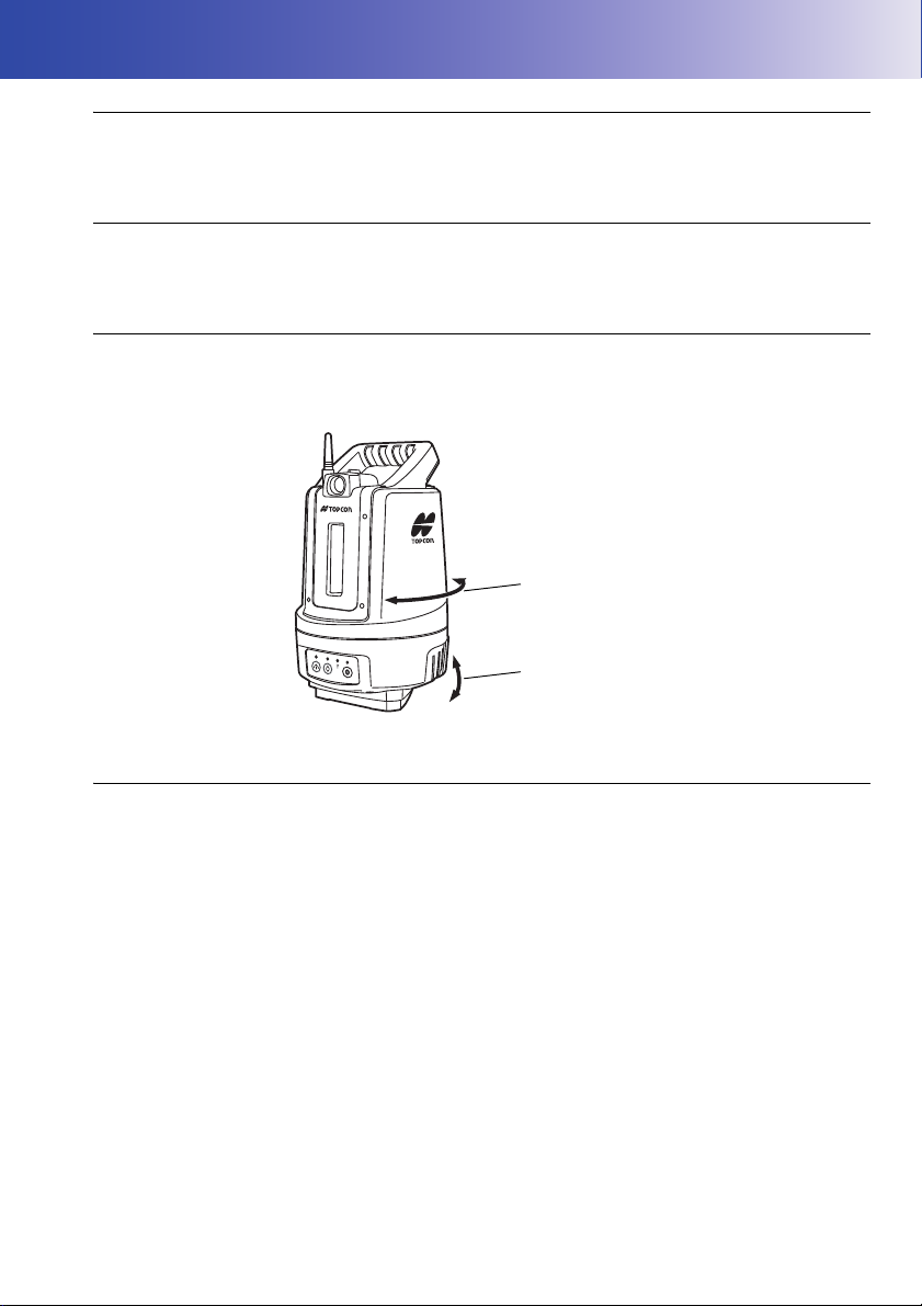
When the power is turned ON
(Auto leveling)
When the power is turned ON or OFF
(Auto rotation)
Charging Battery
• Be sure to charge the battery within the charging temperature range.
Charging temperature range : 0 to 40°C
Warranty policy for Battery
• Battery is an expendable item. The decline in retained capacity depending on the repeated charging/
discharging cycle is out of warranty.
About operation when the power is turned ON/OFF
This instrument operates as shown below and performs auto leveling/auto rotation when the power of
the instrument is turned ON or OFF. Do not touch the instrument during operation. Doing so may
cause injury.
Precautions concerning water and dust resistance
Dustproof and waterproof performance of the instrument comply with IP65. Please read the following
carefully before using.
• Close the battery cover tightly.
• Make sure that moisture or dust particles do not come in contact with the terminal or connectors.
Operating the instrument with moisture or dust on the terminal or connectors may cause damage to
the instrument.
• Make sure that the inside of the carrying case and the instrument are dry before closing the case. If
moisture is trapped inside the case, it may cause the instrument to rust.
• If there is a crack or deformation in the rubber packing for the battery cover or external interface
hatch, stop using and replace the packing.
• To retain the waterproof property, it is recommended that you replace the rubber packing once every
two years. To replace the packing, contact your local sales representative.
4
Page 8

2. PRECAUTIONS
Other precautions
• Do not insert a foreign object into the instrument during the auto leveling. Doing so will cause a
failure.
• Never place the instrument directly on the ground. Sand or dust may cause damage to the screw
holes or the centering screw on the base plate.
• Protect the instrument from heavy shocks or vibration.
• Protect the instrument from rain or drizzle with an umbrella or waterproof cover.
• Never carry the instrument on the tripod to another site.
• Turn the power off before removing the battery.
• Remove the battery before placing the instrument in its case.
• Make sure that the instrument and the protective lining of the carrying case are dry before closing the
case. The case is hermetically sealed and if moisture is trapped inside, the instrument could rust.
• Consult your local dealer before using the instrument under special conditions such as long periods
of continuous use or high levels of humidity. In general, special conditions are treated as being
outside the scope of the product warranty.
Maintenance
• Wipe off moisture completely if the instrument gets wet during survey work.
• Always clean the instrument before returning it to the case. The lens requires special care. First,
dust it off with the lens brush to remove tiny particles. Then, after providing a little condensation by
breathing on the lens, wipe it with the wiping cloth.
• Store the instrument in a dry room where the temperature remains fairly constant.
• Check the tripod for loose fit and loose screws.
• If any trouble is found on the rotatable portion, screws or optical parts (e.g. lens), contact your local
dealer.
• When the instrument is not used for a long time, check it at least once every 3 months.
• Every 4,000 to 5,000 hours operation in total, change grease of driving parts. Contact your local
dealer for the maintenance.
• When removing the instrument from the carrying case, never pull it out by force. The empty carrying
case should be closed to protect it from moisture.
• Check the instrument for proper adjustment periodically to maintain the instrument accuracy.
Exporting this product (Relating EAR)
• This product is equipped with the parts/units, and contains software/technology, which are subject
to the EAR (Export Administration Regulations). Depending on countries you wish to export or bring
the product to, a US export license may be required. In such a case, it is your responsibility to obtain
the license. The countries requiring the license as of May 2013 are shown below. Please consult
the Export Administration Regulations as they are subject to change.
North Korea
Iran
Syria
Sudan
Cuba
URL for the EAR of the US: http://www.bis.doc.gov/policiesandregulations/ear/index.htm
5
Page 9

2. PRECAUTIONS
Exporting this product (Relating telecommunications regulations)
• Wireless communication module is incorporated in the instrument. Use of this technology must be
compliant with telecommunications regulations of the country where the instrument is being used.
Even exporting the wireless communication module may require conformity with the regulations.
Exceptions from responsibility
• The user of this product is expected to follow all operating instructions and make periodic checks
(hardware only) of the product’s performance.
• The manufacturer, or its representatives, assumes no responsibility for results of faulty or intentional
usage or misuse including any direct, indirect, consequential damage, or loss of profits.
• The manufacturer, or its representatives, assumes no responsibility for consequential damage, or
loss of profits due to any natural disaster, (earthquake, storms, floods etc.), fire, accident, or an act
of a third party and/or usage under unusual conditions.
• The manufacturer, or its representatives, assumes no responsibility for any damage (change of
data, loss of data, loss of profits, an interruption of business etc.) caused by use of the product or
an unusable product.
• The manufacturer, or its representatives, assumes no responsibility for any damage, and loss of
profits caused by usage different to that explained in the operator’s manual.
• The manufacturer, or its representatives, assumes no responsibility for damage caused by incorrect
operation, or action resulting from connecting to other products.
6
Page 10
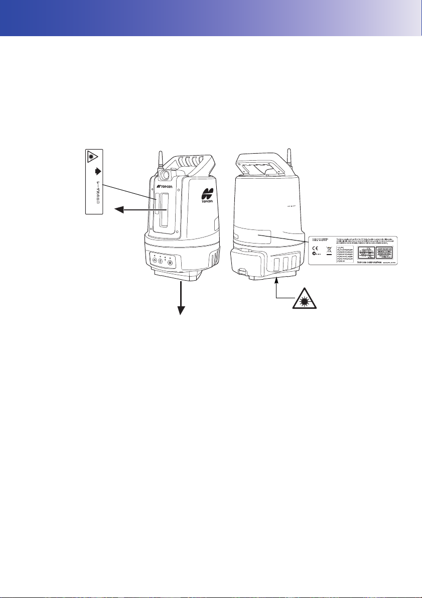
3. LASER SAFETY INFORMATION
A laser beam is emitted
from here
A laser beam is emitted from
here
AVOID EXPOSURE-Laser radiation
is emitted from this aperture.
The instrument is classified as the following class of Laser Product according to IEC Standard
Publication 60825-1 Ed.2.0: 2007 and United States Government Code of Federal Regulation FDA
CDRH 21CFR Part 1040.10 and 1040.11 (Complies with FDA performance standards for laser
products except for deviations pursuant to Laser Notice No.50, dated June 24, 2007.)
• EDM device : Class 3R Laser Product
• Laser pointer : Class 3R Laser Product
• Laser plummet : Class 2 Laser Product
Please read the following safety instructions carefully before using the LN-100.
Warning
• Use of controls or adjustments or performance of procedures other than those specified herein may
result in hazardous radiation exposure.
• Never intentionally point the laser beam at another person. The laser beam is injurious to the eyes
and skin. If an eye injury is caused by exposure to the laser beam, seek immediate medical attention
from a licensed ophthalmologist.
• Do not look directly into the laser beam. Doing so could cause permanent eye damage.
• Do not stare at the laser beam. Doing so could cause permanent eye damage.
• Never look at the laser beam through a telescope, binoculars or other optical instruments. Doing so
could cause permanent eye damage.
• Sight targets so that the laser beam does not stray from them.
Caution
• Perform checks at start of work and periodic checks and adjustments with the laser beam emitted
under normal conditions.
• When the instrument is not being used, turn off the power.
• When disposing of the instrument, destroy the battery connector so that the laser beam cannot be
emitted.
7
Page 11

3. LASER SAFETY INFORMATION
• Avoid setting the instrument at heights at which the path of the laser may strike pedestrians or
drivers at head height. Operate the instrument with due caution to avoid injuries that may be caused
by the laser beam unintentionally striking a person in the eye.
• Never point the laser beam at mirrors, windows or surfaces that are highly reflective. The reflected
laser beam could cause serious injury
• Only those who have received training as per the following items shall use this product.
• Read this manual for usage procedures for this product.
• Hazardous protection procedures (read "LASER SAFETY INFORMATION")
• Requisite protective gear (read "LASER SAFETY INFORMATION")
• Accident reporting procedures (stipulate procedures beforehand for transporting the injured and
contacting physicians in case there are laser-induced injuries).
• Persons working within the range of the laser beam are advised to wear eye protection which
corresponds to the laser wavelength of the instrument being used.
• Areas in which the laser is used should be posted with a standard laser warning sign.
• When using the laser-pointer function, be sure to turn OFF the output laser after distance
measurement is completed. Even if distance measurement is canceled, the laser-pointer function is
still operating and the laser beam continues to be emitted.
8
Page 12
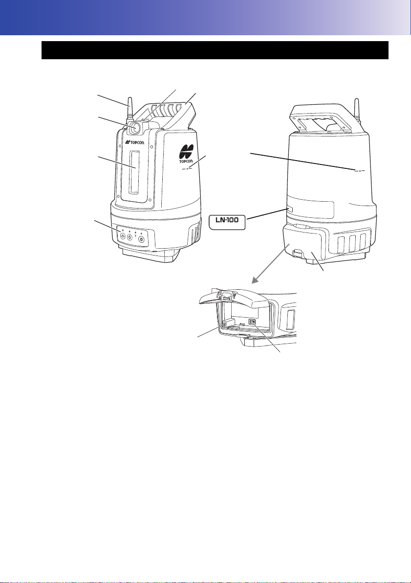
4. NOMENCLATURE AND FUNCTIONS
Wireless
antenna
Guide light
Operation
panel
Battery cover
Handle
Instrument
height mark
W-LAN mode selector
switch
Reset switch
Window
Position where the
serial number is
printed
Sighting collimator
4.1 Parts of the Instrument
Instrument height mark
The height of the instrument is as follows:
176 mm (from the position where a tripod is mounted to the instrument height mark)
“About the instrument height when setting the instrument point” on page 20
Sighting collimator
Use this function to align the direction (horizontal only) of the instrument with the survey point.
Look through the sighting collimator and align the window with the direction of the prism.
Reset switch
This function resets the W-LAN setting to the default factory setting.
"8.2 What to Do When" on page 25
Do not use this switch under normal circumstances.
9
Page 13

4. NOMENCLATURE AND FUNCTIONS
W-LAN LED
Power LED
Auto leveling LED
Laser plummet/
Laser pointer LED
Power switchLaser plummet
switch
Auto leveling switch
Wireless antenna
This antenna may be damaged depending on how it is handled. Be careful not to hit the antenna while
working, as it sticks out from the instrument.
4.2 Control Panel
Explanation of the operation panel
Name Function details
Power switch Power ON: Press it for a short time
Power OFF: Hold down the switch for more than 1 second
Power LED Off: Power OFF
W-LAN mode selector switch
(inside the battery cover)
Lighting up in green: Power is ON
Blinking in green: During Power-OFF-process
Blinking in red: Battery voltage dropped
Mode A: Flip the switch to the right
Mode B: Flip the switch to the left
10
Page 14

4. NOMENCLATURE AND FUNCTIONS
W-LAN LED When it is Mode A
Laser plummet switch Laser plummet ON: Press it
Connection waiting state: Blinking in green every 1 second
(repeating a cycle in which the LED
is on for 1 second and then off for
1 second)
Connecting: Lighting up in green
When it is Mode B
Connection waiting state: Blinking in green quickly
(repeating a cycle of quick on twice,
followed by 2 seconds off)
Connecting: Lighting up in green
When an error is detected in the W-LAN setting item:
Lighting up in red
Laser plummet OFF: Press and hold (More than 1 second).
“Laser plummet ON/OFF and brightness adjustment” on
page 11
Laser plummet/
Laser pointer LED
Auto leveling switch Starts auto leveling: Press it while auto leveling is stopped.
Auto leveling LED Blinking in green: In auto leveling
Off: Laser plummet or laser pointer is OFF
Blinking in green: Laser plummet or laser pointer ON
Stops auto leveling: Press it again while auto leveling is being
Extends the leveling screw:
Lighting up in green: Within the range of inclination
Lighting up in red: Outside the range of inclination
Blinking in red: Outside the range of auto leveling
performed.
Hold it down.
compensation (±6 minutes)
compensation (±6 minutes or over)
“Auto leveling” on page 18
Displaying battery life
The battery life is low when the power LED is blinking in red and a beep sound (repeating beeps) is
heard. Exchange the battery. The battery life of the instrument is displayed on the controller.
Refer to the instruction manual of the controller.
Laser plummet ON/OFF and brightness adjustment
The operation method of the laser plummet is as follows:
Function Description
Turn ON the laser plummet Press the {laser plummet switch} for a short time.
Turn OFF the laser plummet Hold down the {laser plummet switch} for at least 1 second or it
Turn up the brightness Pressing the {laser plummet switch} for a short time while the
The laser plummet lights up with the stored brightness.
turns OFF automatically about five minutes after the laser
plummet is turned ON. The brightness used when the laser
plummet turned OFF is stored.
laser plummet is turned ON turns up the brightness by one level,
up to level 5. After reaching level 5, it goes back to level 1.
11
Page 15

5. PREPARATION
Guides
Slot 1
Slot 2
Charging
lamp
Grooves
5.1 Using the Battery
Battery charging
The battery was not charged at the factory. Charge the battery fully before using the instrument.
• The charger will become rather hot during use. This is normal.
• Do not use to charge batteries other than those specified.
• The charger is for indoor use only. Do not use outdoors.
• Batteries cannot be charged, even when the charging lamp is flashing, when the temperature is
outside the charging temperature range.
• Remove batteries from the charger before putting into storage.
• When not in use, disconnect the power cable plug from the wall outlet.
• Store the battery in a dry room where the temperature is within the following ranges. For long-term
storage, the battery should be charged at least once every six months.
Storage period Temperature range
1 week or less -20 to 50°C
1 week to 1 month -20 to 45°C
1 month to 6 months -20 to 40°C
6 months to 1 year -20 to 35°C
• Batteries generate power using a chemical reaction and as a result have a limited lifetime. Even
when in storage and not used for long periods, battery capacity deteriorates with the passage of
time. This may result in the operating time of the battery shortening despite having been charged
correctly. In this event, a new battery is required.
PROCEDURE
1. Connect the power cable to the charger and
plug the charger into the wall outlet.
2. Mount the battery in the charger by matching
the grooves on the battery with the guides on
the charger.
12
Page 16

5. PREPARATION
3. When charging starts, the lamp starts blinking.
4. The lamp lights when charging is finished.
5. Remove the battery and unplug the charger.
• Slots 1 and 2:
The charger starts charging the battery mounted first. If you place two batteries in the charger, the
battery in slot 1 is charged first, and then the battery in slot 2. (
• Charging lamp:
The charging lamp is off when the charger is outside the charging temperature range or when the
battery is mounted incorrectly. If the lamp is still off after the charger falls within its charging
temperature range and the battery is mounted again, contact your local dealer. (
• Charging time per battery (at 25°C):
BDC70:about 5.5 hours
step 2)
steps 2 and 3)
13
Page 17

5. PREPARATION
Installing the battery
Mount the charged battery.
• Use the attached battery (BDC70).
• When installing/removing the battery, make sure that moisture or dust particles do not come in
contact with the inside of the instrument.
• Be careful not to shut the battery cover on your fingers.
• Before removing the battery, turn off the power to the instrument. If the battery is removed while the
power is switched on, a warm boot may occur. File and folder data may be lost as a result.
• Do not open the battery cover while the power is on.
• Remove batteries from the surveying instrument or charger before putting into storage.
PROCEDURE
1. Push the catch on the battery cover upwards
to open the cover.
2. Check the orientation of the terminal of the
battery, and then insert the battery by sliding it
to the right and pressing against the main unit.
• Do not insert the battery diagonally, as this
may damage the main unit or the battery
terminal.
3. Close the battery cover.
Make sure it clicks.
14
Page 18

5. PREPARATION
Master machine
Slave machine
Master machine
Slave
machine
5.2 W-LAN Connection with the Controller
There are two methods to set up a W-LAN connection between the instrument and the controller:
Mode A connection
This is a one-to-one connection using the instrument as a master machine and the controller as a
slave machine for W-LAN connection. When using the Mode A connection, the instrument performs
as a DHCP server.
For details of the connection method, refer to the instruction manual of W-LAN Config for LN-100.
Mode B connection
Connect via other access point (as the master machine) using the instrument and the controller as
slave machines for W-LAN connection.
For details of the connection method, refer to the instruction manual of W-LAN Config for LN-100.
• The network settings of Mode A and Mode B are saved one each.
15
Page 19

Connection setting items
Item Selection item Default factory setting
SSID Fixed Model name _ serial number
Security None/WEP/WPA/WPA2 WPA2
Password
(Security key)
Mode A
Channel 1 to 11 11
IP address Fixed 192.168.0.1
Subnet mask Fixed 255.255.255.0
DHCP function Fixed DHCP server enabled
DHCP lease address Fixed 192.168.0.10 to
SSID Up to 32 bytes No setting
Security None/WEP/WPA/WPA2 None
Password
(Security key)
Mode B
IP address xxx.xxx.xxx.xxx format No setting
Subnet mask xxx.xxx.xxx.xxx format No setting
DHCP function DHCP client / static IP DHCP client
WEP64:
String of 5 characters
(e.g. RIVER) or
10 hexadecimal characters
(e.g. 12345678AF)
WEP128:
String of 13 characters or
26 hexadecimal characters
WPA/WPA2:
String of 8 to 63 characters or
64 hexadecimal characters
WEP64:
String of 5 characters or
10 hexadecimal characters
WEP128:
String of 13 characters or
26 hexadecimal characters
WPA/WPA2:
String of 8 to 63 characters or
64 hexadecimal characters
5. PREPARATION
(e.g. LN-100_AB1234)
00serial number
(e.g. 00AB1234)
192.168.0.25
No setting
• After purchasing the instrument, change the password for Mode A to other than the serial number.
• If you forget the password, refer to "8.2 What to Do When" on page 25.
16
Page 20

5. PREPARATION
5.3 Setting Up the Instrument
Power ON/OFF
Caution
This instrument automatically operates when the power is turned ON or OFF. Do not
touch the instrument during operation. Doing so may cause injury.
PROCEDURE: Power ON
1. Turn the power ON.
Press the {Power switch} on the operation panel to turn the power ON.
When the power is turned ON, the power LED turns on. After the leveling automatically has
started, the instrument rotates automatically.
• Avoid a W-LAN connection during auto leveling when setting up the instrument.
• After the rotation starts, do not touch the instrument until it stops at the original position.
Refer to “Auto leveling” on page 18 for information on auto leveling.
• Auto Power OFF function:
If no key operation or no data communication has been performed for about 30 minutes, the power
turns OFF automatically.
• If the power cannot be turned ON even when the battery is mounted or if the power turns OFF as
soon as the power turns ON, it is thought that the battery life is gone. Change it for a fully charged
battery.
“Displaying battery life” on page 11
Procedure: Power OFF
1. Hold down the {Power switch} for about 1 second.
17
Page 21

5. PREPARATION
Auto leveling
Caution
Do not touch the instrument during auto leveling. Doing so may cause injury.
• By performing auto leveling, the center of the instrument is automatically leveled within the range
of ±30". After that, if the inclination of the main unit exceeds the range of inclination
compensation (±6'), the red LED will light up. In this case, auto leveling will not automatically
start. Perform auto leveling again.
PROCEDURE
1. Press {Auto leveling switch} while auto leveling is stopped.
The auto leveling LED starts blinking in green and auto leveling starts. After completing auto
leveling, the LED lights up in green.
• If a foreign object gets caught in the auto leveling section, hold down {Auto leveling switch}.
If the leveling screw is extended, remove the foreign object, and restart auto leveling.
The following describes how to press {Auto leveling switch} and its relationship with the
operation of the instrument:
Auto leveling
switch
Short press One beep After the beep sound is heard,
Long press
(1 second)
Hold down Two beeps After the beep sound is heard, the leveling screw starts extending. It
*1)
If a sound other than these beep sound patterns is heard, refer to the instruction manual of TSShield.
*2)
When auto leveling is performed by pressing {Auto leveling switch} for a long time (1 second), the
same auto leveling operation as that performed when {Power switch} is turned ON is performed.
Measurement by rotating the instrument 180° calibrates the inclination sensor.
Beep sound
*1)
Two beeps After the beep sound is heard,
While auto leveling is stopped
auto leveling starts when you
release the switch.
auto leveling starts when you
release the switch. At this time,
the instrument rotates 180°.*2)
stops when you release the switch.
While auto leveling is being
performed
After the beep sound is heard, auto
leveling stops when you release the
switch.
18
Page 22

Centering
Centering screw
Survey point
PROCEDURE
1. Make sure the legs are spaced at equal intervals
and the head is approximately level.
Set the tripod so that the head is positioned over the
survey point.
Make sure the tripod shoes are firmly fixed in the
ground.
2. Place the instrument on the tripod head.
Supporting it with one hand, tighten the centering
screw on the bottom of the unit to make sure it is
secured to the tripod.
5. PREPARATION
3. Aim a laser beam at the survey point.
Turn the {Laser Plummet Switch} ON and loosen the
centering screw.
Fix the centering screw after aiming the laser beam
at the survey point.
• The laser light blinks when the instrument is
performing auto leveling.
19
Page 23

5. PREPARATION
Survey point
Instrument height
About the instrument height when setting the instrument point
The instrument height entered for setting the instrument point is the height from the survey point to the
instrument height mark.
Refer to the instruction manual of the controller for the settings.
20
Page 24

6. OUTLINE OF SURVEY
Center of the instrument
Usable range
Outside the Distance
Measurement Range
Guide light
Green Red
The instrument can perform a stakeout survey and a side shot method.
Use the controller for measurement.
6.1 Usable Range
The following shows the usable range of the instrument.
Do not operate the instrument out of the usable range shown below.
㼻
25
0.9m
22m
100m
0m
• Distance Measurement
The distance measurement limit of the instrument is a radial shape with a radius of 104 m from the
center of the instrument.
Moving the target at the limit of the distance measurement range may result in the target being
located outside the range within which measurement is possible.
5㼻
10m
4m
6.2 Functions of Guide Light
By setting the guide light to “ON,” you can tell from a distance about the state of the instrument and
the direction to move the pole, by reference to the color of the light and the blinking pattern.
The left of the guide light is green and the right is red.
21
Page 25

7. CHECK
µí µí²°í
Йоуфтхнеоф
рпйоф²
Йоуфтхнеоф
рпйоф±
Небухтенеофрпйофв Небухтенеофрпйофб
ATP2 : The 360° Prism should be set up so that a pair of diametrically-opposed hexagonal
points on its rubber flanges are aligned with the sighting direction of the instrument
(see the diagram below).
ATP2S : The 360° Prism should be set up so that a pair of diametrically-opposed marks on
top of the prism are aligned with the sighting direction of the instrument.
: Hexagonal points
: Prism sighting direction
LN-100 is a precision instrument. It must be inspected before use so that it always performs accurate
measurements.
In addition, the instrument should be inspected with special care after it has been stored a long time,
transported, or when it may have been damaged by a strong shock.
Setting Up the Instrument
Perform a setup operation under an environment where the sunlight is weak and not fluctuating
as well as LN-100 and the targets can be set as illustrated below.
• To perform checking efficiently, mark the four points described below using setting-out function
in advance.
• Place the instrument and targets in a straight line when looking from directly above.
• Acceptable range of each point position is ±5cm in all directions.
• Set LN-100 and the targets on a substantially horizontal place (such as a floor, level ground,
tripods of the same height). (The guideline for difference in height at 30 m is about 30 cm)
• Use ATP2 (360° prism) or ATP2S (360° slide prism) for the target.
• To set ATP2S, lower the height of the prism to reduce the setting error.
Measurement
• Sighting can be more accurately performed by facing the ATP2/ATP2S toward the instrument.
22
Page 26

7. CHECK
µí µí²°í
Йоуфтхнеоф
рпйоф²
Йоуфтхнеоф
рпйоф±
Небухтенеофрпйофв Небухтенеофрпйофб
µí µí²°í
Йоуфтхнеоф
рпйоф²
Йоуфтхнеоф
рпйоф±
Небухтенеофрпйофв Небухтенеофрпйофб
µí µí²°í
Йоуфтхнеоф
рпйоф²
Йоуфтхнеоф
рпйоф±
Небухтенеофрпйофв Небухтенеофрпйофб
µí µí²°í
Йоуфтхнеоф
рпйоф²
Йоуфтхнеоф
рпйоф±
Небухтенеофрпйофв Небухтенеофрпйофб
1. Set the instrument at instrument point 1.
2. Measure the target set at measurement point a to record the coordinates.
Because the target is re-measured at measurement point a after shifting to measurement point b,
the position should be marked (positioning accuracy is approximately ±1mm).
3. Set the target at measurement point b.
4. Measure the target set at measurement point b to record the coordinates.
5. Set up the instrument at instrument point 2.
6. Measure the target set at measurement point b to record the coordinates.
7. Set the target at measurement point a.
Return to the measurement position shown in 2. above.
8. Measure the target set at measurement point a to record the coordinates.
23
Page 27

Measurement results recording table:
D
1
X
1 a,
X
1 b,
–()
2
Y
1 a,Y1 b,
–()
2
+=
D
2
X
2 a,
X
2 b,
–()
2
Y
2 a,Y2 b,
–()
2
+=
Z1Z
1 a,Z1 b,
–=
Z
2Z2 a,Z2 b,
–=
ED mm[]
D
1D2
–()
2
------------------------
1000×=
EZ mm[] Z
2Z1
–()1000×=
Instrument point Target X [m] Y [m] Z [m]
1
2
a
b
a
b
X
1,a :
X
1,b :
X
2,a :
X
2,b :
Y
1,a :
Y
1,b :
Y
2,a :
Y
2,b :
Calculation
Obtain the distance error (ED) and the vertical error (EZ) from the following formulas:
Z
Z
Z
Z
7. CHECK
1,a :
1,b :
2,a :
2,b :
Assessment
Confirm that the distance error (ED) and the vertical error (EZ) fall within the following ranges:
• Distance error
• Vertical error
• If the error falls out of the range, contact your local dealer.
-6 (mm) < ED < +6 (mm)
-11.6 (mm) < EZ < +11.6 (mm)
24
Page 28

8. TROUBLESHOOTING
If there is a problem, check the table below and follow the suggestions.
8.1 LED Display
LED display What is happening How to resolve
Auto leveling LED is blinking
in red.
W-LAN LED is blinking in red An error occurred in the
Because the instrument is
inclined excessively, auto
leveling cannot be performed.
hardware.
8.2 What to Do When
Conditions Causes How to resolve
Forgot the password. ---
Signal is weak. Use the instrument in a good
Incorrect security settings Configure the security setting to
Wireless connection to the
controller is disabled.
When the W-LAN mode is set to Mode B
Wireless connection to the
controller is disabled.
*) How to press the reset switch
Set the W-LAN mode to Mode A, and then turn the power ON.
Before being connected to the wireless (while the W-LAN LED is blinking), hold down the reset
switch until it beeps twice.
Incorrect password Enter the correct password.
Another controller is already
communicating.
It takes too long for WPA2
authentication.
Access point cannot be found. The channel of the access point
Attempting to connect with an
access point that cannot be
connected unless the MAC
address is registered in advance.
Perform auto leveling again after
leveling the surface, such as the
flat top surface of the tripod,
where the instrument is installed.
A repair is necessary. Contact
your local dealer.
Press the reset switch*) to reset
to the factory default settings.
Configure the communication
settings again.
signal environment.
the same as that of LN-100.
Check whether it is
communicating with another
controller.
Wait until the authentication
completes.
may be set to 12 or greater (out of
the search range of LN-100).
Change the channel.
MAC address for LN-100 needs
to be registered in advance.
At this time, the W-LAN is configured as follows:
Security: WPA2
Password: 00 serial number
25
Page 29

9. SPECIFICATIONS
282.324
0.294362 p×
1 0.003661 t×+
------------------------------------------
–
0.04127 e×
1 0.003661 t×+
------------------------------------------
+
Atmospheric Correction Factor (ppm) =
Usable range
Altitude angle ±25° (0.9 to 22 m)
Difference of altitude ±10 m (22 to 100 m)
Horizontal angle 360°
Distance 0.9 to 100 m
(
"6.1 Usable Range" on page 21)
General accuracy (While measuring coordinates at 50 m)
Reproducibility
Horizontal positioning 3 mm (2σ)
Altitude positioning 6 mm (2σ)
Absolute positioning
Horizontal positioning ±5 mm
Altitude positioning ±10 mm
Angle measurement section
Method Absolute rotary encoder method
Resolving power 1"
Inclination compensation section
Method Hydraulic dual-axis inclination sensors
Compensation range ±6' 00"
Distance measuring section
Method Retardation survey method (Prism distance measurement only)
Measurable range 0.9 to 100 m
Update rate of distance data 20 Hz
Light source Laser diode
Wavelength 690 nm
Laser class Class 1 equivalent when measuring the distance
Atmospheric correction Entry of the temperature and atmospheric pressure
(Depending on the application)
(Default factory setting : 15°C, 1013hPa)
Atmospheric correction factor (ppm)
Prism constant correction Yes
*1: When using ATP2/ATP2S
Weather conditions for measurement: Other than bad weather, such as rain, dense fog, and
strong heat haze
*1
*2
*2: Atmospheric correction factor (ppm)
The atmospheric correction value is calculated using the following formula and set into the
memory.
t : Air temperature (°C)
p : Pressure (hPa)
e : Water vapor pressure (hPa)
h : Relative humidity (%)
E : Saturated water vapor pressure
26
Page 30

9. SPECIFICATIONS
E6.1110
7.5 t×()
t237.3+()
----------------------------
×=
eh
E
100
--------- -×=
• e (water vapor pressure) can be calculated using the following formula.
Laser pointer section (Availability of the function depends on the application to be used.)
Light source Laser diode
Wavelength 690 nm
Laser class Class 3R
Spot size Width: 7 mm / Length: 8 mm (at a distance of 20 m)
Width 16.9 mm / Length: 19.3 mm (at a distance of 50 m)
Auto tracking section
Method Image sensor method using a coaxial optical system for beam
emission and reception
Auto trackable range
0.9 to 100 m
Light source Laser diode
Wavelength 793 nm
Laser class Class 1
*1: When using ATP2/ATP2S
Weather conditions for measurement: Other than bad weather, such as rain, dense fog, and
strong heat haze
Ranging tracking optical system
Structure Coaxial optical system for tracking a measurement of distance
Objective aperture Ø16.5 mm
Focus distance 50 mm
*1
Motor actuator
Motion range 360° (Horizontal)
Maximum rotation speed 60°/second (10 rpm)
(The time required for 180° rotation: 3.0 seconds)
Minimum feed angle (operated from the external application)
Auto leveling section
Method Main unit integral type
Auto leveling mechanism Dual-axis
Leveling range ±3°
Guide light
Light source Light-emitting diode (LED) (Red 626 nm / Green 524 nm)
Visible range Greater than 8° at horizontal (full length: 7 m at a distance of 50
15" (±3.75 mm equivalent at a distance of 50 m)
m)
27
Page 31

9. SPECIFICATIONS
Laser plummet section
Light source Laser diode
Wavelength 635 nm
Laser class Class 2
Beam accuracy 1.0 mm or less (At the height of the head of a tripod of 1.3 m)
Spot diameter Ø3 mm or less (At the height of the head of a tripod of 1.3 m)
Communication section
W-LAN Supports 802.11 n/b/g
Antenna for W-LAN External
Security (Selection item) None/WEP/WPA/WPA2 (Default factory setting : WPA2)
Communication distance 100 m (Depending on the controller to be used)
Power source section
Standard battery BDC70 lithium-ion battery
Continuous service hour (at 20°C)
About 5 hours
Battery (BDC70)
Nominal voltage 7.2 V
Capacity 5,240 mAh
Dimensions 40 (W) X 70 (D) X 40 (H) mm
Weight About 197 g
Charger (CDC68A)
Input voltage 100 to 240 V AC
Charging time (at 25°C per battery)
BDC70 About 5.5 hours (Charging may take longer than this at low or
Range of charging temperature
Range of storage temperature
Dimensions 94 (W) X 102 (D) X 36 (H) mm
Weight About 170 g
high temperature.)
0 to 40°C
-20 to 65°C
Backup power supply (for the clock)
Power off function Yes (30 minutes)
General
Panel section
Number of keys (types)
Number of LEDs (types)
W-LAN mode switching Mode A/B switching (Inside the battery box)
Self-diagnosis function Yes
Buzzer Beep only
Sighting collimator Yes
Dimensions 185 (W) X 196 (D) X 295 (H) mm
Lithium battery (More than 8 years)
3 types (Power source, laser plummet, auto leveling)
4 types (Power source, laser plummet, auto leveling, W-LAN)
28
Page 32

Instrument height 176 mm
Weight About 4 kg (Including the battery)
Environmental resistance
Operating temperature -20 to 50°C (No condensation)
Storage temperature -30 to 60°C (No condensation)
Dustproof / Waterproof IP65
9. SPECIFICATIONS
29
Page 33

10.REGULATIONS
Region/
Country
U.S.A. FCC
Directives/
Regulations
-Class A
Labels/Declarations
FCC Compliance
WARNING:
Changes or modifications to this unit not expressly approved by the
party responsible for compliance could void the user's authority to
operate the equipment.
NOTE:
This equipment has been tested and found to comply with the limits
for a Class A digital device pursuant to Part 15 of the FCC Rules.
These limits are designed to provide reasonable protection against
harmful inter-ference when the equipment is operated in a commercial
environment. This equipment generates, uses, and can radiate radio
frequency energy and, if not installed and used in accordance with the
operator’s manual, may cause harmful interference to radio
communications. Operation of this equipment in a residential area is
likely to cause harmful interference in which case the user will be
required to correct the interference at his own expense.
Means of conformity
This device complies with part 15 of the FCC Rules, Operation is
subject to the following two conditions: (1) This device may not cause
harmful interference, and (2) this device must accept any interference
received, including interference that may cause undesired operation.
This transmitter must not be co-located or operated in conjunction
with any other antenna or transmitter.
This equipment complies with FCC radiation exposure limits set forth
for uncontrolled equipment and meets the FCC radio frequency (RF)
Exposure Guidelines in Supplement C to OET65. This equipment has
very low levels of RF energy that is deemed to comply without
maximum permissive exposure evaluation (MPE). But it is desirable
that it should be installed and operated with at least 20cm and more
between the radiator and person’s body (excluding extremities:
hands, wrists, feet and ankles).
Declaration of Conformity
Model Number: LN-100
Trade Name: TOPCON CORPORATION
Manufacturer
Name: TOPCON CORPORATION
Address: 75-1, Hasunuma-cho, Itabashi-ku, Tokyo,
174-8580 JAPAN
Country:JAPAN
U.S.A. Representative
Responsible party: TOPCON POSITIONING SYSTEMS, INC.
Addr ess 7400 National Drive Livermore, CA94551, U.S.A
Telephone number: 925-245-8300
30
Page 34

10. REGULATIONS
Region/
Country
California,
U.S.A
California,
U.S.A
California
and NY,
U.S.A.
Directives/
Regulations
Proposition
65
Perchlorate
Material
(CR Lithium
Battery)
Recycling
Batteries
Labels/Declarations
31
Page 35

10. REGULATIONS
Region/
Country
Canada ICES
EU
Directives/
Regulations
EMC-Class B
R&TTEClass 2
-Class A
Labels/Declarations
This Class A digital apparatus meets all requirements of Canadian
Interference-Causing Equipment Regulations.
Cet appareil numérique de la Class A respecte toutes les exigences
du Règlement sur le matériel brouilleur du Canada.
This class A digital apparatus complies with Canadian ICES-003.
Cet appareil numerique de la classe A est conforme a la norme
NMB-003 du Canada.
Operation is subject to the following two conditions: (1) this device
may not cause interference, and (2) this device must accept any
interference, including interference that may cause undesired
operation of this device.
This equipment complies with IC radiation exposure limits set forth
for uncontrolled equipment and meets RSS-102 of the IC radio
frequency (RF) Exposure rules. This equipment should be installed
and operated with at least 20cm and more between the radiator and
person’s body (excluding extremities: hands, wrists, feet and ankles).
EU R&TTE-
Class 2
R&TTE Directive
LN-100
Hereby, TOPCON CORP., declares that the above-mentioned
equipment is in compliance with the essential requirements and
other relevant provisions of Directive 1999/5/EC.
Please inquire below if you wish to receive a copy of Topcon's
Declaration of Conformity.
Topcon Europe Positioning B.V.
Essebaan 11, 2908 LJ Capelle a/d IJssel,
The Netherlands
Tel:+31-10-4585077 Fax:+31-10-2844949
http://www.topcon-positioning.eu/index.asp
32
Page 36

10. REGULATIONS
Region/
Country
EU WEEE
EU EU Battery
Australia C-Tick
Directives/
Regulations
Directive
Directive
Labels/Declarations
33
Page 37

http://www.topcon.co.jp
©2013 TOPCON CORPORATION
ALL RIGHTS RESERVED
Please see the attached address list or the following website for contact addresses.
GLOBAL GATEWAY http://global.topcon.com/
 Loading...