

Page 1

SURVEYING INSTRUMENTS
IP-S3 HD1
Mobile Mapping System
72008 92080
INSTALLATION MANUAL
For more information contact Synergy Positioning Systems or
visit the Synergy Positioning Systems website at www.synergypositioning.co.nz
All branches: Phone 0800 867 266 Email: info@synergypositioning.co.nz
Page 2

i
HOW TO READ THIS MANUAL
Thank you for selecting the IP-S3.
• Please read this Instruction manual carefully, before using this product.
• The specifications and general appearance of the instrument are subject to change without prior
notice and without obligation by TOPCON CORPORATION and may differ from those appearing in
this manual.
• The content of this manual is subject to change without notice.
• Some of the diagrams shown in this manual may be simplified for easier understanding.
• This manual is protected by copyright and all rights are reserved by TOPCON CORPORATION.
• Except as permitted by Copyright law, this manual may not be copied, and no part of this manual
may be reproduced in any form or by any means.
• This manual may not be modified, adapted or otherwise used for the production of derivative works.
Symbols
The following conventions are used in this manual.
: Indicates precautions and important items which should be read before
operations.
: Indicates the chapter title to refer to for additional information.
: Indicates supplementary explanation.
Notes regarding manual style
• All other company and product names featured in this manual are trademarks or registered
trademarks of each respective organization.
Page 3

ii
CONTENTS
1. PRECAUTIONS FOR SAFE OPERATION ................................................ 1
2. PRECAUTIONS ......................................................................................... 3
3. LASER SAFETY INFORMATION .............................................................. 6
4. SYSTEM CONFIGURATION ..................................................................... 7
4.1 Standard Package Components ........................................................ 7
IP-S3 Cube ...............................................................................................7
4.2 Optional Accessories ......................................................................... 7
Mount kit ...................................................................................................7
Wheel encoder .........................................................................................7
Gasket ......................................................................................................7
Car ...........................................................................................................8
Roof carrier ..............................................................................................8
Overfender ...............................................................................................8
Personal computer ...................................................................................8
AC/DC inverter .........................................................................................8
Tools ........................................................................................................8
4.3 Vehicle Preparation ............................................................................ 8
5. INSTALLING AND ARRANGING CABLES ............................................... 9
6. IP-S3 CUBE DIAGRAM ........................................................................... 10
7. OPERATION FLOW OF IP-S3 SYSTEM................................................. 11
8. PREPARE THE VEHICLE ....................................................................... 12
8.1 Install the Roof Carrier ..................................................................... 12
8.2 Install the Mount Kit ......................................................................... 12
8.3 Install the Wheel Encoder ................................................................ 16
Required Parts .......................................................................................16
Installing the wheel encoder ...................................................................16
Installing the wheel encoder cable .........................................................17
8.4 Install the Gasket ............................................................................. 18
9. INSTALLING THE IP-S3 CUBE............................................................... 19
9.1 Install the IP-S3 Cube ...................................................................... 19
9.2 Connect the Cables ......................................................................... 23
Fixing the timing box ..............................................................................23
Connecting the power cable ...................................................................23
Connecting the power cable (battery side) .............................................24
Preparing a personal computer ..............................................................25
Connect the Computer Cable .................................................................25
Connect the Timing Box Ethernet Cable ................................................26
Connect the Indicator Box Cable ...........................................................27
Connect the Wheel Encoder Cable to the Box .......................................27
Connect the IP-S3 Cube Cables ............................................................28
Fixing the Cables ..................................................................................29
Page 4

iii
9.3 Indicator Box .................................................................................... 30
Status LED .............................................................................................30
GNSS LED .............................................................................................30
LED display ............................................................................................31
Resetting the timing box .........................................................................31
Clearing NVRAM (Initializing GNSS) ......................................................31
9.4 Removing of IP-S3 Cube ................................................................. 32
10. SPECIFICATIONS ................................................................................... 33
11. REGULATIONS ....................................................................................... 35
Page 5

1
1. PRECAUTIONS FOR SAFE OPERATION
For the safe use of the product and prevention of injury to operators and other persons as well as
prevention of property damage, items which should be observed are indicated by an exclamation point
within a triangle used with WARNING and CAUTION statements in this operator’s manual.
The definitions of the indications are listed below. Be sure you understand them before reading the
manual’s main text.
Definition of Indication
General
WARNING
Ignoring this indication and making an operation error could possibly
result in death or serious injury to the operator.
CAUTION
Ignoring this indication and making an operation error could possibly
result in personal injury or property damage.
This symbol indicates items for which caution (hazard warnings inclusive) is urged.
Specific details are printed in or near the symbol.
This symbol indicates items which are prohibited. Specific details are printed in or near
the symbol.
This symbol indicates items which must always be performed. Specific details are printed
in or near the symbol.
Warning
Do not use the unit in areas exposed to high amounts of dust or ash, in areas where there
is inadequate ventilation, or near combustible materials. An explosion could occur.
Do not perform disassembly or rebuilding. Fire, electric shock, burns, or hazardous
radiation exposure could result.
Carefully attach the IP-S3 cube to the mount kit. Damage to the instrument or serious
injury can occur.
To avoid injury, stop the car engine and apply the emergency brake before mounting or
removing the device.
Before approaching the extended slide bar, look around carefully. The slide bar may hit
your head or face to cause injury.
When securing the instrument in the carrying case make sure to set all the locks. Failure
to do so could result in the instrument falling out while being carried, causing injury.
Caution
Do not use the carrying case as a footstool. The case is slippery and unstable so a
person could slip and fall off it.
Page 6

2
1. PRECAUTIONS FOR SAFE OPERATION
Power Supply
Do not place the instrument in a damaged case. The instrument could be dropped
and cause injury.
Carefully carry this instrument. Dropping it will cause injury of persons or trouble/wrong
operation of the instrument.
Warning
Do not use voltage other than the specified power supply voltage. Fire or electrical shock
could result.
Do not use damaged power cords or plugs. Fire or electric shock could result.
Do not use power cords other than those designated. Fire could result.
Do not connect or disconnect power supply plugs with wet hands. Electric shock could
result.
To avoid fire and electric shock in the event of an instrument malfunction, immediately
turn off the power if you notice heat, smoke or smell coming from the instrument or if you
detect other problems.
To avoid electric shock, turn off the power of the car before connecting the power cable.
Page 7

3
2. PRECAUTIONS
Shock to the instrument
When carrying or transporting this instrument, put it into the special shipping case (Optional). If the
instrument is exposed to extreme shock, it may malfunction or be operated wrongly.
Dew condensation
After operating the instrument in a place with much rain/moisture, dry the instrument completely and
then store it into the case. If the instrument is stored with water, dew condensation will occur in the
instrument to cause malfunction or wrong operation.
Extreme temperature change
If this instrument is subject to extreme temperature change (for example, carrying it from a warm room
to the cold outdoors), the survey accuracy is temporarily changed. Accustom the instrument to the
use environment before using it.
Mounting to a car
Before mounting/removing this instrument, put the car on a flat and stable place with enough extent
and brightness, and turn off the engine. Mount the roof carrier securely according to the roof carrier's
instruction manual. Unless you observe this caution, serious injury may occur.
Stain
When the window unit in the laser scanner is dirty, moisten a soft, clean lint-free cloth with water and
wipe off the window unit with the cloth. If the instrument with the dirty window unit is used, the
accuracy is sometimes affected adversely.
Influence by electric wave
When using this instrument in a place with the strong electric waves mentioned below, it does not
operate normally from time to time.
• Near a transceiver or other devices generating strong electric waves
• Near an electric wave source such as television or radio
Driving
Drive the vehicle at legal speed.
Follow all driving laws for your area while driving the vehicle. When starting, steering or braking
suddenly, check the mounting status of the device.
When this instrument has been mounted on the car, the car height increases to approximately 2.3m
for sedans. Drive the car carefully where the height is limited.
Survey in rainy weather
Do not perform survey in rainy weather. Sometimes the instrument cannot survey the object
accurately.
Page 8
4
2. PRECAUTIONS
Mounting the wheel encoder
To mount the wheel encoder, install the overfender according to the vehicle laws in your area, and
obtain the automobile inspection certificate again.
Privacy
The data collected with this device can include images that violate privacy laws. Delete or alter images
that violate privacy rights before making the data publicly available.
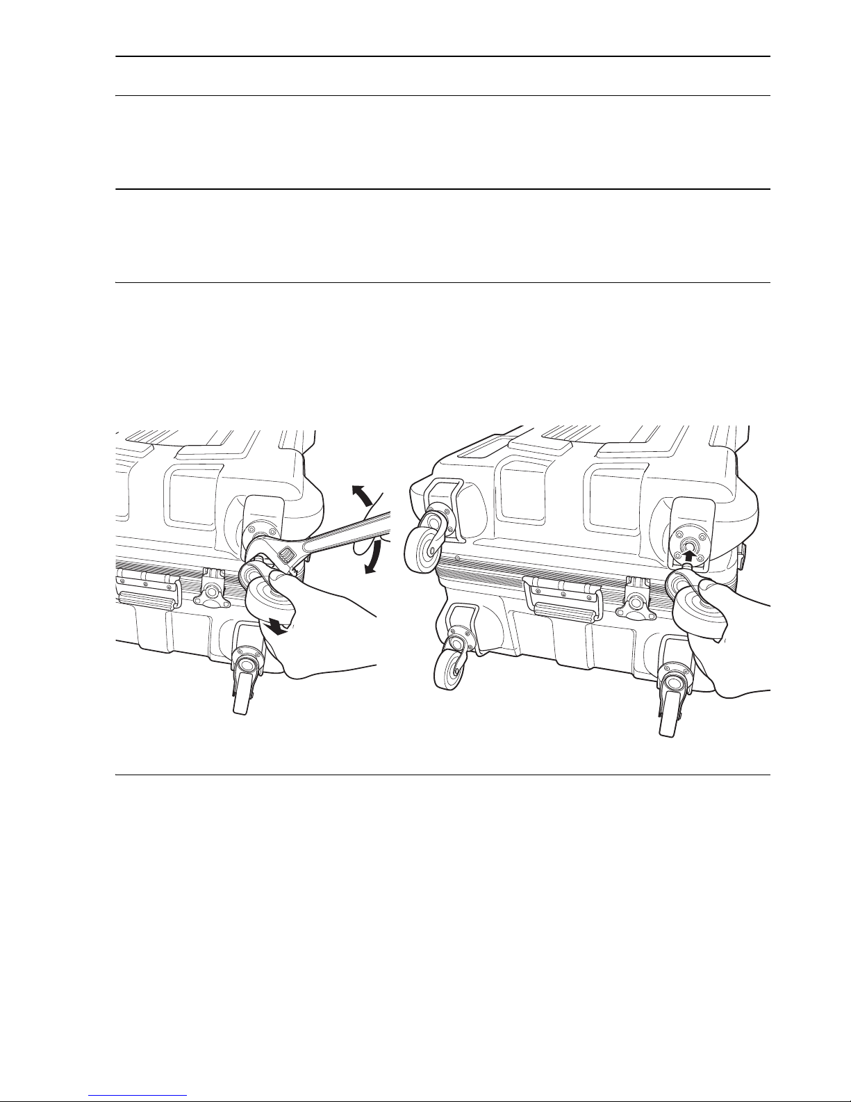
Removing/attaching casters on the carrying case(Optional)
Remove casters from the case as needed.
Maintenance
• Wipe off moisture completely if the instrument gets wet during survey work.
• Always clean the instrument before returning it to the case.
• Store the instrument in a dry room where the temperature remains fairly constant.
• Even when the instrument is not used for a long time, check its operation at least every 3 months.
• When removing the instrument from the carrying case, never pull it out by force. The empty carrying
case should be closed to protect it from moisture.
• Check the instrument for proper adjustment periodically to maintain the instrument accuracy.
Attachment
Removal
If you cannot remove casters by pulling
them with your hand, use commercially
available tools sold in stores.
Page 9

5
2. PRECAUTIONS
Exporting this product (Relating EAR)
• This product is equipped with the parts/units, and contains software/technology, which are subject
to the EAR (Export Administration Regulations). Depending on countries you wish to export or bring
the product to, a US export license may be required. In such a case, it is your responsibility to obtain
the license. The countries requiring the license as of May 2013 are shown below. Please consult
the Export Administration Regulations as they are subject to change.
North Korea
Iran
Syria
Sudan
Cuba
URL for the EAR of the US: http://www.bis.doc.gov/policiesandregulations/ear/index.htm
Exceptions from responsibility
• The user of this product is expected to follow all operating instructions and make periodic checks
(hardware only) of the product’s performance.
• The manufacturer, or its representatives, assumes no responsibility for results of faulty or intentional
usage or misuse including any direct, indirect, consequential damage, or loss of profits.
• The manufacturer, or its representatives, assumes no responsibility for consequential damage, or
loss of profits due to any natural disaster, (earthquake, storms, floods etc.), fire, accident, or an act
of a third party and/or usage under unusual conditions.
• The manufacturer, or its representatives, assumes no responsibility for any damage (change of
data, loss of data, loss of profits, an interruption of business etc.) caused by use of the product or
an unusable product.
• The manufacturer, or its representatives, assumes no responsibility for any damage, and loss of
profits caused by usage different to that explained in the operator’s manual.
• The manufacturer, or its representatives, assumes no responsibility for damage caused by incorrect
operation, or action resulting from connecting to other products.
Page 10
6
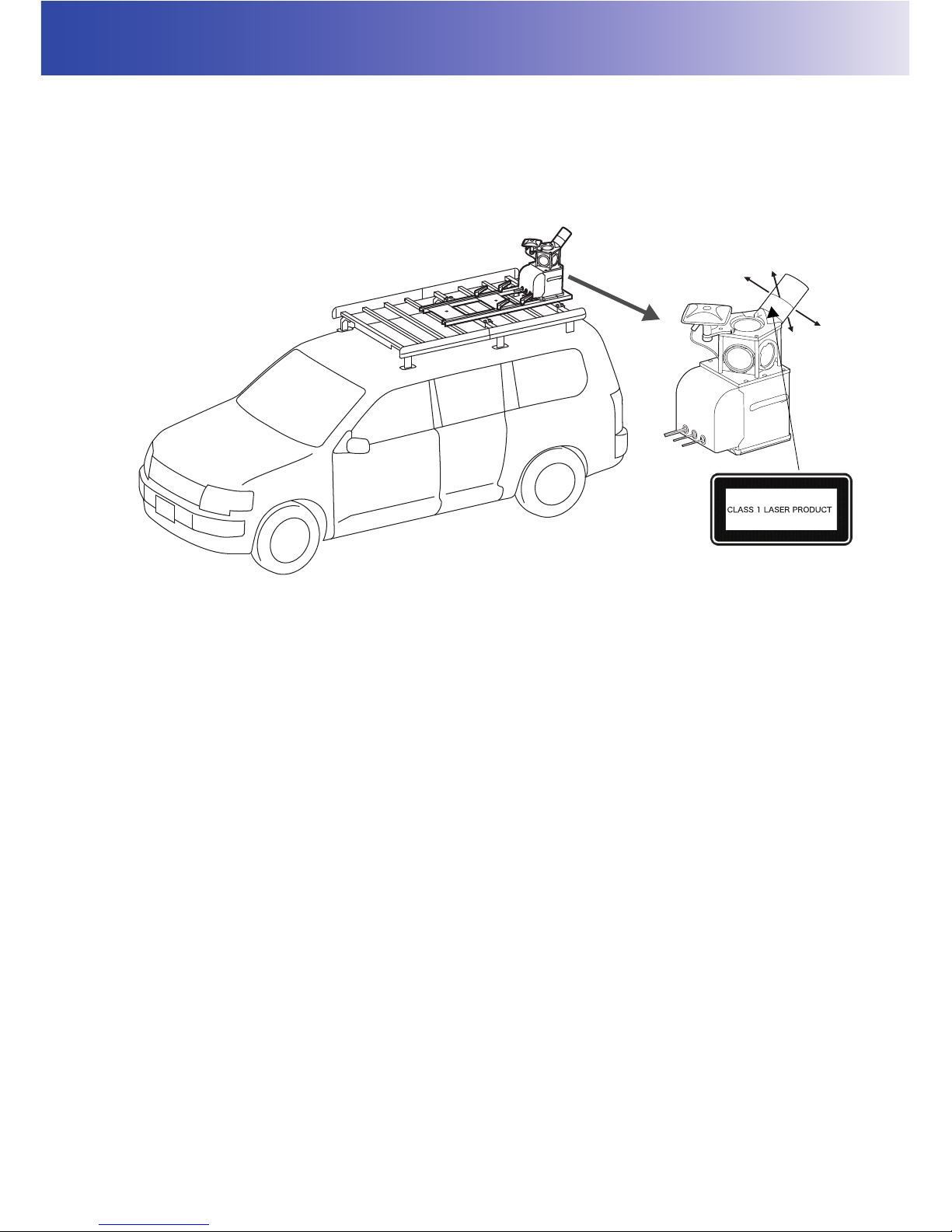
3. LASER SAFETY INFORMATION
The instrument is classified as the following class of Laser Product according to IEC Standard
Publication 60825-1 Ed.2.0: 2007 and United States Government Code of Federal Regulation FDA
CDRH 21CFR Part 1040.10 and 1040.11 (Complies with FDA performance standards for laser
products except for deviations pursuant to Laser Notice No.50, dated June 24, 2007.)
Please read the following safety instructions carefully before using the IP-S3.
Warning
• Use of controls or adjustments or performance of procedures other than those specified herein may
result in hazardous radiation exposure.
• Never intentionally point the laser beam at another person. The laser beam is injurious to the eyes
and skin. If an eye injury is caused by exposure to the laser beam, seek immediate medical attention
from a licensed ophthalmologist.
Caution
• Perform checks at start of work and periodic checks and adjustments with the laser beam emitted
under normal conditions.
• When the instrument is not being used, turn off the power.
• When disposing of the instrument, destroy the battery connector so that the laser beam cannot be
emitted.
Laser beam is emitted
from here. (360° rotation)
Class 1 Laser Product
Page 11

7
4. SYSTEM CONFIGURATION
IP-S3 Cube
Refer to "STANDARD PACKAGE COMPONENTS" (enclosed paper).
IP-S3 cube has already been assembled. Because it has already been adjusted, do not disassemble
it.
Mount kit
Slide bar (with clamp lever) : 1 set
Carrier plate : 2 pcs.
Slide base : 2 pcs.
Step screw (M6) : 2 pcs.
Cable tie :20 pcs.
Carrier base A : 8 pcs.
Carrier base B : 8 pcs.
Hexagonal socket head cap screw
(M10×55mm) :16 pcs.
Spare hexagonal socket head cap screw : 4 pcs.
Washer assembled hexagonal socket head cap screw
(M10×20mm) : 1 pc.
Spare washer assembled hexagonal socket head cap screw : 1 pc.
Plain washer (M10) :16 pcs.
Spare plain washer : 4 pcs.
Spring washer (M10) :16 pcs.
Spare spring washer : 4 pcs.
Wheel encoder
Wheel encoder : 1 pc.
Nut : Size and quantity depend on the car model.
Tire nut quantities and wheel encoder shape are different between vehicles. Contact your local dealer
for more information.
Gasket
When cables are arranged in the car, a gasket is used to minimize the clearance of the window glass.
4.1 Standard Package Components
4.2 Optional Accessories
Page 12

8
4. SYSTEM CONFIGURATION
Car
Wheel encoder types are determined by the car model. Contact your local dealer. To prevent the car
from being reflected within the scan range of scanner, select a car model where you can mount the
instrument at the rear.
Roof carrier
Mount the roof carrier onto the car securely.
Overfender
When using the wheel encoder, an overfender is required for most of the car models. To mount the
overfender, obtain the automobile inspection certificate again. Contact your dealer both when
selecting a car model and when mounting the overfender.
Personal computer
For the recommended specifications, refer to the Mobile Master Office and Mobile Master Field
instruction manuals.
AC/DC inverter
This inverter is necessary to activate a personal computer. Prepare an AC/DC inverter according to
the power consumption of your personal computer.
Tools
When installing the mount kit, the following tools are necessary.
• Allen wrench 8mm (for hexagonal socket head cap screw)
• Allen wrench 4mm (for step screw)
4.3 Vehicle Preparation
Page 13
9
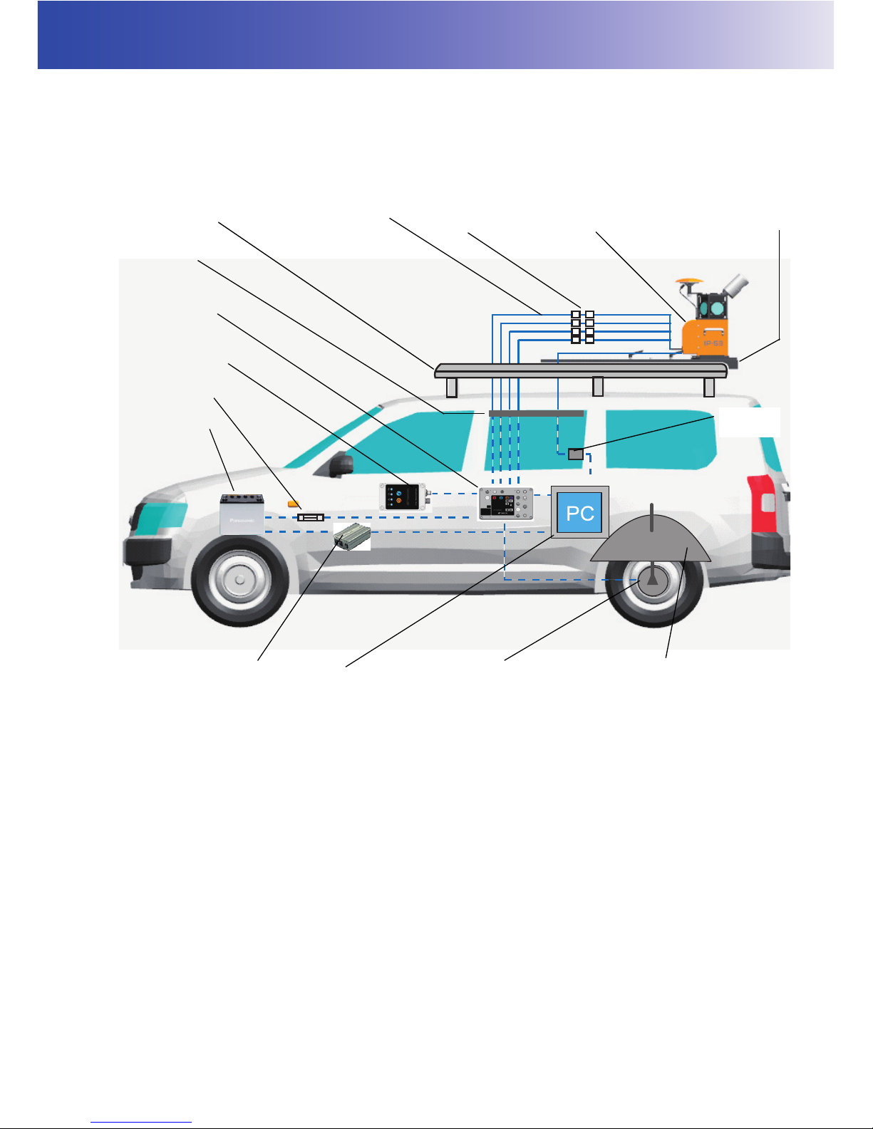
5. INSTALLING AND ARRANGING CABLES
The outline for installing the devices is shown below.
The cables from the IP-S3 cube are connected to the devices from the inside of the vehicle through
the windows.
Roof carrier
Mount kit
IP-S3 cube
Gasket
Car battery
Personal computer
(for collecting data/setting
devices)
Wheel encoder
Overfender
Cable
Timing box
Indicator box
Fuse (30A)
AC/DC inverter
USB3.0
repeater
Relay connector
Page 14

10
6. IP-S3 CUBE DIAGRAM
The IP-S3 cube has already been assembled. Because it has already been adjusted, do not
disassemble it.
Scanner
GNSS antenna
Spherical
camera
IMU
(in the case)
Handle
IMU cable
Scanner cable
GNSS cable
USB 3.0 cable (long)
Camera cable
Page 15

11
7. OPERATION FLOW OF IP-S3 SYSTEM
The operation outline and the relevant instruction manuals are shown below.
Collect data
Install the IP-S3 cube when surveying (parts that are removed from the car)
• Installing the roof carrier
• Installing the mount kit
• Installing the wheel encoder
• Installing the gasket
Advance preparation (parts that are not removed from the car)
Remove the devices
IP-S3 HD1 Installation Manual (this manual)
• Installing the IP-S3 cube to the mount kit
• Connecting the cables
• Checking the operation
• Preparing the personal computer
IP-S3 HD1 Installation manual (this manual)
• Collecting the base station (known point) data
• Checking the operation of sensors
• Collecting the IP-S3 data
Mobile Master Field Instruction Manual
Post-processing
Subsequent work
• Post-processing
• Making the point cloud data (Coloring the point cloud)
Mobile Master Office Instruction Manual
Page 16

12
8. PREPARE THE VEHICLE
When preparing the vehicle, install the following devices.
1. Mount the roof carrier onto the car. For details, refer to the roof carrier's instruction manual.
Mount the carrier plate onto the roof carrier bar using the following procedure. (The carrier plate has
the binding band to clamp the cables.)
1. Put the carrier base A on the roof carrier bar and align the hole position. (4 places)
2. Put one carrier plate on the carrier base A.
3. Mount the carrier plate to carrier base using the 4 hexagonal socket head cap screws on both
ends of the plate.
4. Repeat step 3 for the other carrier plate.
8.1 Install the Roof Carrier
8.2 Install the Mount Kit
Roof carrier
Carrier base A
Carrier base B
Carrier plate
Roof carrier
Roof carrier bar
Hexagonal socket
head cap screw
Carrier plate
Spring washer
Plain washer
Page 17

13
8. PREPARE THE VEHICLE
5. Mount the side base to the carrier plate using carrier base B and the 8 hexagonal head cap
screws. The side base must be pointed in the direction shown below.
When the instrument is shipped, the slide bases are secured to the slide bar with 4 clamp levers.
Detach the clamp levers from the slide bar before using the slide bases.
Slide base
Hexagonal socket head cap screw(8pcs.)
Carrier plate
Slide base
(Pay attention to the
mounting direction.)
Long hole
Hexagonal socket
head cap screw
Spring washer
Plain washer
Car traveling direction
Clamp lever
Slide bar
Page 18

14
8. PREPARE THE VEHICLE
6. Remove the 4 clamp levers, spring washers, and plain washers from the side bar.
7. Put the slide bar on the slide base.
8. As shown in the illustration below, locate where the sidebar is fully extended and securely tighten
the clamp lever and step screw.
Torque the step screw to 5N-m.
9. Adjust the slide base to be parallel to the slide bar, making sure clearances are the same.
10. Tighten the 8 hexagonal head cap screws, and torque to 24.4N-m.
Clamp lever
Step screw
Slide bar
Slide base
Slide bar
Clamp lever
Step screw
Slide base
Extend fully.
Spring washer
Plain washer
Page 19

15
8. PREPARE THE VEHICLE
11. Loosen the 4 clamp levers, retract the slide bar, and place it in the the center of the roof carrier.
12. Securely tighten the 4 clamp levers by hand.
The knob parts of all clamp levers used for this product can be rotated by pulling them in the direction
indicated by the arrow in the diagram below. When tightening the clamp levers, rotate the knobs so
that you can easily apply your force.
Clamp lever
Slide bar
Retract.
Clamp lever(knob)
Page 20

16
8. PREPARE THE VEHICLE
Required Parts
The number in parentheses is quantity.
Installing the wheel encoder
1. Remove the wheel nuts from one of the right and left tires.
2. Attach the wheel encoder nuts.
8.3 Install the Wheel Encoder
Wheel encoder (1) Wheel encoder cable (1)
Wheel encoder nut and bolt
(Size and quantity are different between car
models.)
Genuine nut
Special nut
Page 21

17
8. PREPARE THE VEHICLE
3. Make a hole on the overfender of the rear tire to fix the wheel encoder bar.
4. Pass the wheel encoder bar through the hole on the overfender of the rear tire.
5. Align the hole of wheel encoder with the nut of the rear tire.
6. Attach the wheel encoder bolt.
Installing the wheel encoder cable
1. Connect the cable of rear tire to the wheel encoder. (The connection for the IP-S3 cube will be
mentioned later.)
Wheel encoder bar
Hole
Overfender
Wheel encoder
Special bolt
Wheel encoder
Wheel encoder cable
[Sensor Side] is written on the tag
of this part.
Page 22

18
8. PREPARE THE VEHICLE
• Arrange the wheel encoder cable so that it stays within the vehicle width.
• The quantity of wheel encoder parts is different from vehicle to vehicle. Contact your local dealer for
more information.
After mounting the IP-S3 cube on the roof of the vehicle, connect it to the timing box using the included
cables. Keep the rear window slightly open to route the cables to the timing box. Use a gasket to
decrease the gap in the open window.
1. Trim the gasket to fit the rear window.
2. Slightly lower the window, and attach the gasket.
8.4 Install the Gasket
Gasket
Window glass of rear seat
Page 23

19
9. INSTALLING THE IP-S3 CUBE
To prevent theft, only install the IP-S3 cube to the mount kit when surveying.
The IP-S3 cube has already been calibrated. Do not disassemble it.
1. Loosen the 4 clamp levers of the slide bar.
2. Extend the slide bar in the direction shown in the diagram below.
3. Tighten the 4 clamp levers.
9.1 Install the IP-S3 Cube
Warning
Carefully attach the IP-S3 cube to the mount kit. Damage to the instrument or serious
injury can occur.
Before approaching the extended slide bar, look around carefully. The slide bar may hit
your head or face to cause injury.
Clamp lever
Slide bar
Extend.
Page 24

20
9. INSTALLING THE IP-S3 CUBE
4. Make sure that the four quick shoe lock pins are lowered.
5. Loosen the 2 clamp levers of the quick shoe.
6. Hold both handles of the IP-S3 cube, and place it on the quick shoe as shown in the image
below.
Be careful not to catch the cable.
Lock pin
Clamp lever
Quick shoe
Lock pin
Handle
Quick shoe
Page 25

21
9. INSTALLING THE IP-S3 CUBE
7. Place the IP-S3 cube against the fixing pins of the quick shoe. Then, raise the lock pins to make
sure that the IP-S3 cube is secured.
8. Tighten the two clamp levers.
9. Tighten the hexagonal socket head cap screw with washer (M10Å~20mm) from the bottom of the
quick shoe.
The IP-S3 cube is now installed.
Fixing pin
Lock pin
Lock pin
Clamp lever
Handle
Washer assembled hexagonal
socket head cap screw
Page 26

22
9. INSTALLING THE IP-S3 CUBE
10. Loosen the clamp lever of the slide bar, and retract the slide bar as shown in the image below.
11. Tighten the clamp lever of slide bar.
• When surveying, extend and use the slide bar.
• If you open the hatchback while the slide bar is extended, the hatchback may be damaged.
Before opening the hatchback, retract the slide bar.
Page 27

23
9. INSTALLING THE IP-S3 CUBE
After mounting the IP-S3 cube on the roof of the vehicle, connect it to the timing box using the included
cables. Keep the rear window slightly open to route the cables to the timing box. Do not allow any slack
in the cables.
Fixing the timing box
To prevent the timing box from moving while the car is running, adhere Velcro tape to the rear surface
of timing box as shown below.
Connecting the power cable
1. Connect the IP-S3 side connector ([Timing Box Side] is written on the tag) of the power cable to
the power supply port (POWER) of timing box. Do not supply power to the timing box.
• If power is supplied to the box at this point, it may draw too much power and cause the connector
to fail.
• The above illustration shows the position of each connector.
• Do not connect the cables incorrectly.
• The color sheet on the timing box shows the color of each cable tag.
9.2 Connect the Cables
Warning
To avoid electric shock, turn off the car engine before connecting the power cables.
Timing box
Velcro tape
Page 28

24
9. INSTALLING THE IP-S3 CUBE
Connecting the power cable (battery side)
1. Connect the power cable to the car battery.
The wire on the battery side of the power cable is exposed. Topcon recommends placing the
exposed wire inside a connector. For safety and ease of use, connect the red cable to the
positive (+) terminal, and the black cable to the negative (-) terminal.
Timing box
Power cable
Sheet
Timing box switch
Example of the connection unit
Power cable
[+] terminal
[-] terminal
Car battery
Page 29

25
9. INSTALLING THE IP-S3 CUBE
• Power is supplied to IP-S3 from the car battery directly. Even if the car engine is turned off, IP-S3
operates and the car battery discharges power. Whenever the car engine stops, turn off the timing
box switch.
• When connecting the power cable, turn off the timing box switch.
• When connecting all cables, turn off the timing box switch.
Preparing a personal computer
A computer running Microsoft Windows is required to set up the IP-S3 cube, check the settings, and
collect data. An AC power supply is required for the computer.
Set up your computer away from heat and moisture and direct sunlight.
Connect the Computer Cable
1. Connect the Ethernet cable to the Ethernet port on the computer.
2. Connect the USB 3.0 cable to the USB jack of the computer.
Do not connect the USB 3.0 cable to the computer while Windows is starting. The camera does not
operate normally from time to time. In such a case, start Windows correctly, then connect the cable.
Ethernet cable
[PC Side] is written on the tag of this part.
USB3.0 cable
[PC Side] is written on the tag of this part.
Page 30

26
9. INSTALLING THE IP-S3 CUBE
Connect the Timing Box Ethernet Cable
1. Remove the cap from the timing box Ethernet cable.
2. Connect the IP-S3 side of the Ethernet cable to the Ethernet port of the IP-S3 cube.
Ethernet cable
[Timing Box Side] is written on the
tag of this part.
Ethernet port(Blue)
Page 31

27
9. INSTALLING THE IP-S3 CUBE
Connect the Indicator Box Cable
1. Remove the cap from the indicator box port.
2. Using the indicator box cable, connect the timing box to the indicator box as shown below.
Connect the Wheel Encoder Cable to the Box
1. Remove the cap from the timing box Encoder port.
2. Connect the wheel encoder cable to the Encoder port on the timing box. The encoder port is
located next to the wheel encoder port. See "8.3 Install the Wheel Encoder" on page 16 for more
information.
Indicator box cable
[Timing Box Side] is written
on the tag of this part.
[Indicator Side] is
written on the tag of
this part.
Wheel encoder cable
[Timing Box Side] is written on
the tag of this part.
Encoder port (white)
Page 32

28
9. INSTALLING THE IP-S3 CUBE
Connect the IP-S3 Cube Cables
1. Connect all cables from the timing box to the IP-S3 cube, and ty-wrap them for easy storage.
Cube side
IMU (Tag: brown)
Camera (Tag: purple)
Scanner (Tag: red)
GNSS (Tag: white)
Timing Box side
[1]IMU
(Tag: brown)
[2]Camera
(Tag: purple)
[3]Scanner
(Tag: red)
[4]GNSS
(Tag: white)
[Joint Side] is written on
the tag of this part.
[Joint Side] is written on
the tag of this part.
Connect the cables on the timing box side to the ports shown below.
Timing Box
[1]IMU
[2]Camera
[3]Scanner
[4]GNSS
Page 33

29
9. INSTALLING THE IP-S3 CUBE
Fixing the Cables
• After connecting all cables, attach them to the binding band of the carrier plate.
• Fix the cables without excessive tension.
Carrier plate
Connector
Binding band
(Detachable)
Page 34

30
9. INSTALLING THE IP-S3 CUBE
Using the LEDs of the IP-S3 indicator box, check if the IP-S3 system operates properly.
Status LED
After turning the power on, if the Status LED blinks red some part of the IP-S3 system is not operating
correctly.
If the Status LED blinks green, the IP-S3 system is operating correctly and the system can collect data.
It takes approximately 1 minute for the Status LED to register green from turning the power on.
GNSS LED
This LED blinks a different color according to the number of satellites currently being tracked in GPS
and GLONASS. Green indicates GPS and orange indicates GLONASS. Right after the power is ON,
this LED blinks red. A Red blinking LED indicates that the instrument is not surveying. When the single
system is surveying, the LED does not blink red.
For more information on device operation, see the Mobile Master Field Instruction Manual.
9.3 Indicator Box
Status LED
LAN LED
Switch LED
GNSS LED
NVRAM Clear button
System reset
button
Indicator box
Page 35

31
9. INSTALLING THE IP-S3 CUBE
LED display
LED status is described in the table below.
For all errors, except GNSS initialization, follow the steps in "Resetting the Timing Box" below.
For descriptions of errors, see the Mobile Master Field Instruction Manual.
Resetting the timing box
1. Continuously press the System Reset button until the Switch LED blinks slowly.
2. Release the system reset button. The Switch LED blinks rapidly until the timing box is reset.
After resetting is finished, the timing box restarts.
Clearing NVRAM (Initializing GNSS)
1. Continuously press the NAVRAM Clear button until the Switch LED blinks slowly.
2. Release the NVRAM Clear button. The Switch LED blinks rapidly until NVRAM is cleared.
After NVRAM is cleared, the timing box restarts.
LED Indication Contents
Status
Solid red
Startup
Solid orange
Sensor is being initialized.
Solid green
Operating properly
Green blink
Collecting data
Blinks red two times
System error
Blinks red three times GNSS initialization error (Clear NVRAM.)
Blinks red four times
IMU error
Blinks red five times
Scanner data error
Blinks red six times
Scanner synchronization error
LAN
Solid green During Ethernet connection to timing box from
each sensor
Switch
Solid green Within 4 seconds after the switch is pressed
Blinks green slowly Within 4 - 8 seconds after the switch is pressed
Blinks green rapidly Instrument reset or NAVRAM is clearing
GNSS
Blinks red Surveying is not performed
Blinks green
Tracking GPS satellites:
The blinking times indicate the number of
satellites being tracked.
Blinks orange
Tracking GLONASS satellites:
The blinking times indicate the number of
satellites being tracked.
Page 36

32
9. INSTALLING THE IP-S3 CUBE
After surveying, follow the steps below to remove the IP-S3 cube.
1. Disconnect the cables.
2. Loosen the clamp lever of slide bar and extend the slide bar.
3. Loosen the clamp lever of the quick shoe.
4. Pull down the 4 lock pins.
5. Holding both handles, remove the IP-S3 cube as shown in the diagram below.
9.4 Removing of IP-S3 Cube
Lock pin
Clamp lever
Page 37

33
10.SPECIFICATIONS
IP-S3 Timing box
Dimensions 260 (W) × 160 (D) × 121 (H) mm
Weight 3.0kg(6.6lb)
Operating temperature range -20°C to 50°C (-4° to 122°F)
Storage temperature range -30°C to 60°C (-22° to 140°F)
Dustproof/Waterproof IP65 (JIS C0920:2003)
Input/Output port Power supply, Ethernet, scanner, spherical camera,
wheel encoder, IMU, GNSS antenna
Time resolution 10 nsec
Input voltage 9V to 36V
Power consumption 60W (when cube is connected)
GNSS receiver Built-in
Indicator Box
Dimensions 75 (W) × 125 (D) × 34 (H) mm
Weight 0.2kg(4.4lb)
Operating temperature range -20°C to 50°C (-4° to 122°F)
Storage temperature range -30°C to 60°C (-22° to 140°F)
Dustproof/Waterproof IP65 (JIS C0920:2003)
LED Status, LAN, Switch, GNSS
Cube
Dimensions 300 (W) × 500 (D) × 600 (H) mm
Weight 18kg(39.6lb)
Sensors installed in Cube GNSS antenna, IMU, Laser scanner, Spherical camera
Sensors
GNSS receiver
Number of channel 226 channels
GPS L1/L2 carrier, L1CA, L1P, L2P
GLONASS L1/L2 carrier, L1CA, L1P, L2P
Data update 10 Hz
Static survey accuracy H: ±3.0mm + 0.5ppm
V: ±5.0mm + 0.5ppm
Kinematic survey accuracy H: ±10mm + 1ppm
V: ±15mm + 1ppm
Operating temperature range -40°C to 85°C (-40° to 185°F)
Storage temperature range -40°C to 60°C (-40° to 140°F)
Vibration 4G (sine wave), 7.7G (Random vibration)
Shock 30G
GNSS antenna
Operating Frequency Range L1 GPS/GLONASS 1586.5 ± 25MHz
L2 GPS/GLONASS 1236 ± 20 MHz
L-Band 1535 ± 10 MHz
Operating temperature range -50°C to 85°C (-58° to 185°F)
Storage temperature range -55°C to 50°C (-67° to 122°F)
Dustproof/Waterproof IP67 (JIS C0920:2003)
Vibration Random Vibration : IEC 60068-2-34, Test Fd
Sinusoidal vibration : IEC 60068-2-6, Test Fc
Shock Shock : IEC 60068-2-29 Test Ea
Bump : IEC 60068-2-29 Test Eb
Drop : 2m pole drop to concrete
IMU
Gyro bias stability 1°/hr
Page 38

34
10. SPECIFICATIONS
Acceleration bias stability 7.5 mg
Operating temperature range -40°C to 65°C (-40° to 149°F)
Storage temperature range -50°C to 80°C (-58° to 176°F)
Dustproof/Waterproof IP67 (JIS C0920:2003)
Vibration 6Grms(20Hz to 2000Hz)
Shock 7G(6 to 10msec 1/2Sine)
Laser scanner
Point density 700000 points/sec
Valid range 100m
Operating temperature range -10°C to 60°C (-14° to 140°F)
Storage temperature range -40°C to 105°C (-40° to 221°F)
Dustproof/Waterproof IP67 (JIS C0920:2003)
Vibration 3Grms(5Hz to 200Hz)
Shock 500m/s
2
(11msec)
Spherical camera
Camera unit CCD camera (6 pcs.)
Maximum resolution 8000 × 4000 pixels
Operating temperature range 0°C to 45°C (32° to 113°F)
Storage temperature range -30°C to 60°C (-22° to 140°F)
Maximum image capturing
speed 10fps
Wheel encoder
Pulse rate 2500 PPR
Operating temperature range -40°C to 85°C (-40° to 185°F)
Dustproof/Waterproof IP67 (JIS C0920: 2003)
Vibration 100m/s
2
(10Hz to 2000Hz)
Shock 2500m/s
2
(6msec)
General
Absolute coordinates accuracy*1) 50mm@10m distance (1 sigma)
*1) Comparison to 10 known points in 30 times by 30km/h
Surface accuracy*2) 10mm on road surface (1 sigma)
*2) Plane fitting results on flat road surface
Continuous surveying time 4 hours
Page 39

35
11.REGULATIONS
Region/
Country
Directives/
Regulations
Labels/Declarations
U.S.A. FCC
-Class A
FCC Compliance
WARNING:
Changes or modifications to this unit not expressly approved by the
party responsible for compliance could void the user's authority to
operate the equipment.
NOTE:
This equipment has been tested and found to comply with the limits
for a Class A digital device pursuant to Part 15 of the FCC Rules.
These limits are designed to provide reasonable protection against
harmful inter-ference when the equipment is operated in a
commercial environment. This equipment generates, uses, and can
radiate radio frequency energy and, if not installed and used in
accordance with the operator’s manual, may cause harmful
interference to radio communications. Operation of this equipment
in a residential area is likely to cause harmful interference in which
case the user will be required to correct the interference at his own
expense.
California,
U.S.A
Proposition
65
California,
U.S.A
Perchlorate
Material
(CR Lithium
Battery)
Canada ICES
-Class A
This Class A digital apparatus meets all requirements of Canadian
Interference-Causing Equipment Regulations.
Cet appareil numérique de la Class A respecte toutes les
exigences du Règlement sur le matériel brouilleur du Canada.
This class A digital apparatus complies with Canadian ICES-003.
Cet appareil numerique de la classe A est conforme a la norme
NMB-003 du Canada.
Page 40

36
11. REGULATIONS
EU
EMC-Class A
EMC NOTICE
In industrial locations or in proximity to industrial power
installations, this instrument might be affected by electromagnetic
noise. Under such conditions, please test the instrument
performance before use.
This is a CLASS A product. In a domestic environment this product
may cause radio interference in which case the user may be
required to take adequate measures.
Model: Mobile Mapping System IP-S3 HD1
Manufacturer
Name: TOPCON CORPORATION
Address: 75-1, Hasunuma-cho, Itabashi-ku, Tokyo, 174-
8580 JAPAN
Europe Representative
Name: Topcon Europe Positioning B.V.
Representative Director:
Jim Paetz
Address: Essebaan 11, 2908 LJ Capelle a/d IJssel, The
Netherlands
EU WEEE
Directive
Region/
Country
Directives/
Regulations
Labels/Declarations
Page 41

http://www.topcon.co.jp
GLOBAL GATEWAY http://global.topcon.com/
Please see the attached address list or the following website for contact addresses.
©2015 TOPCON CORPORATION
ALL RIGHTS RESERVED
 Loading...