

Page 1

INSTRUCTION MANUAL
LUMINANCE METER
Rev 1.1
Page 2

2 3
Page 3

INTRODUCTION
Thank you so much for your purchasing our TOPCON TECHNOHOUSE Luminance Meter IM-1000.
IM-1000 is a handy type luminance meter that can measure a wide range with high accuracy. This
manual describes the outline, basic operation procedure, specifications and the communication
specifications required for developing the software regarding the Luminance Meter IM-1000. Read
this manual carefully before putting the instrument into operation in a proper manner.
Page 4
DISPLAY FOR SAFE USE
Display
Meaning
DANGER
Ignoring or disregarding this display may result in serious injury
or cause the death of human beings.
WARNING
Ignoring or disregarding this display may result in serious injury
or lead to life threatening situations.
CAUTION
Ignoring or disregarding this display may lead to personal injury
or damage of facilities.
Icon
Meaning
This icon indicates Caution.
Specific content is expressed with words or an image located close to
the icon.
(Example
: Be careful for an electric shock.)
This icon indicates Prohibition.
Specific content is expressed with words or an image located close to
the icon.
(Example : Don’t touch the operating units.)
This icon indicates Mandatory Action.
Specific content is expressed with words or an image located close to
the icon.
(Example : Install the grounding.)
In order to encourage the safe use of products and prevent any danger to the operator and others or
damage to existing facilities, important warnings are put on the products and inserted into the
instruction manuals.
We suggest that everyone understand the meaning of the following displays and icons before reading
the "SAFETY CAUTIONS" and text.
DISPLAYS
• "Personal injury" means an injury, burn or electric shock which does not requir entering or going to
hospital.
• "Damage of facilities" refers to extensive damage to buildings, household belongings, livestock or
pets.
ICONS
4
Page 5
Icons
Prevention Item
Prohibition
Don't use this instrument where combustible steam (for example
gasoline) occurs.
It may cause a fire.
Prohibition
Don't disassemble or modify this instrument.
A fire or electric shock may occur.
Mandatory Action
Use the AC adapter which is an accessory sold separatery.
If not, the AC adapter malfunctions to cause a fire or electric shock.
Prohibition
Don't disassemble the AC adapter.
It may cause a fire or electric shock.
Mandatory Action
Remove dust or water from the outlet of the AC adapter.
If not, a fire may occur.
Mandatory Action
If an abnormal noise, smell or smoke comes in this instrument, turn
off the power and remove the AC adapter from the outlet at once.
A fire will occur if using the instrument without repairing the
troublepoint. Consult with your dealer or TOPCON TECHNOHOUSE.
Icons
Prevention Item
Prohibition
Install the battery to be fit to the specified polarity.
The leakage may cause an injury or malfunction.
Prohibition
Don’t put the instrument on an unstable place (e.g., on an
unsteady table or a sloped surface).
The instrument may fall off or turn over to cause an injury.
Prohibition
Don't pull out or insert the plug by a moistened hand.
It may cause an electric shock.
WARNING
CAUTION
5
Page 6

ESCAPE CLAUSE
• TOPCON shall not take any responsibility for damage due to fire, earthquake, actions by third
persons and other accidents, or the negligence and misuse of the user and use under unusual
conditions.
• TOPCON shall not take any responsibility for damage derived from the inability to use this equipment,
such as a loss of business profit and suspension of business.
• TOPCON shall not take any responsibility for damage caused by operations other than those
described in this Instruction Manual.
• TOPCON shall not take any responsibility for damage caused by operation failures due to
combination with other devices.
CAUTIONS FOR USE
• Be sure to use the standard accessory, nickel hydride battery (charging type) for the instrument. If
you use others except the standard accessory, the instrument may operate irregularly.
• Be sure to use the specified AC adapter for the instrument. Any other AC adapter will cause a
malfunction. The input voltage is AC100 - AC240 and the power supply frequency is 50Hz - 60Hz.
• Be sure to turn off the power switch before connecting/disconnecting an external plug such as the AC
adapter or RS-232C connector.
• When the instrument is not in use for a long time, disconnect the power plug to save the energy.
• Take out the battery to avoid leakage and store the instrument when it is expected to be disused for
a month or more.
• The instrument does not have a waterproof structure. Don’t use or store the instrument where it is
splashed with water or other liquids.
• Don’t measure a bright thing that is beyond the measuring range. The photo detector may be
damaged to hinder the accurate measurement.
• Don’t use the instrument in the place with much dust, high humidity or corrosive gas.
• Don’t use the instrument where the temperature is sharply changed. The instrument has the built-in
temperature compensation circuit. However, it cannot perform measurement precisely in the
environment where the temperature is sharply changed.
• Don’t use or store the instrument where a strong shock (e.g., falling off) or constant vibration is given.
Because the instrument has the precise optical parts, a shock or vibration will cause a malfunction.
When carrying the instrument, do not give a vibration or shock to it directly.
• Store the instrument under the normal temperature condition. Don’t store it under the high
temperature and humidity condition (e.g., in a vehicle).
• The instrument case is made of plastic. Don’t wipe it, using any chemicals (acetone or thinner).
Don’t bring it near any place whose temperature is 50°C or more.
• Make a calibration regarding the instrument about once a year to keep the measurement accuracy.
For the request of calibration, contact your dealer or TOPCON TECHNOHOUSE.
• The data stored in the built-in memory are erased in the calibration of the instrument. Make a
backup file of the necessary data before requesting the calibration.
6
Page 7

USER MAINTENANCE
Unless specified in this manual, the maintenance work shall be conducted only by a trained service
engineer, to ensure the safety and performance of the instrument. The following maintenance work,
however, may be executed by the operator. Regarding the maintenance method, read the applicable
text in this manual.
n Cleaning the instrument cover and beam detector
If the instrument case and beam detector are stained, moisten a soft cloth with the diluted neutral
detergent and, with this cloth, remove the stain. Then, wipe the case and beam detector with a dry,
soft cloth.
The stain, fingerprint or oil on the beam detector sometimes causes a measurement error. Carefully
clean the beam detector. Don’t use acetone, thinner, benzine or other solvents.
7
Page 8

CONTENTS
INTRODUCTION ...................................................................................................................... 3
DISPLAY FOR SAFE USE ........................................................................................................ 4
1.PREPARATION BEFORE USE .................................................................................. 12
1.1. CHECKING THE INSTRUMENT AND ACCESSORIES ................................................... 12
1.2. NAMES AND FUNCTIONS OF COMPONENTS .............................................................. 13
1.2.1. Names and functions of switches on keyboard ......................................................................................... 15
1.2.2. Names and contents of data on the display screen ................................................................................... 17
1.3. PREPARATION................................................................................................................ 18
1.3.1. Connecting the AC adapter ....................................................................................................................... 18
1.3.2. Installing the batteries ............................................................................................................................... 20
1.3.3. Installing personal computer ..................................................................................................................... 21
1.3.4. Turning ON/OFF the power ....................................................................................................................... 22
2.OPERATION OF THE MEASURED VALUE .............................................................. 23
2.1. DISPLAY OF THE MEASURED VALUE ........................................................................... 23
3. SETTING OPERATION............................................................................................... 24
3.1. FUNCTION MODE........................................................................................................... 24
3.1.1. Shifting to function mode/returning to measurement mode ....................................................................... 24
3.1.2. Set item/Data display ................................................................................................................................ 25
3.2. DETAILS OF FUNCTION MODE ..................................................................................... 26
3.2.1. Setting the averaging count ...................................................................................................................... 26
3.2.2. Setting the interval mode .......................................................................................................................... 26
3.2.3. Setting the interval measurement conditions ............................................................................................ 27
3.2.4. Setting the manual measurement conditions ............................................................................................ 27
3.2.5. Setting continuous measurement .............................................................................................................. 27
3.2.6. Setting the reference light source.............................................................................................................. 28
3.2.7. Setting the sample light source ................................................................................................................. 28
3.2.8. Setting the reference value ....................................................................................................................... 28
3.2.9. Setting the spectral correction ................................................................................................................... 29
3.2.10. Setting the tristimulus values correction .................................................................................................. 29
3.2.11. Setting the wireless LAN ......................................................................................................................... 30
3.2.12. Setting the wireless LAN IP address ....................................................................................................... 30
3.2.13. Setting the wireless LAN subnet mask .................................................................................................... 31
3.2.14. Setting the wireless LAN port number ..................................................................................................... 31
3.2.15. Setting the wireless LAN access point .................................................................................................... 32
3.2.16. Setting the wireless LAN WEP ................................................................................................................ 32
3.2.17. Setting the wireless LAN PASS PHRASE ............................................................................................... 33
3.2.18. Setting the RS-232C baud rate ............................................................................................................... 33
8
Page 9

3.2.19. Setting the back light ............................................................................................................................... 34
3.2.20. Setting the measurement data automatic saving function ................................................................................ 34
3.2.21. Setting the measurement data history clearing function .................................................................................. 34
4. COMMUNICATION WITH PERSONAL COMPUTER ................................................ 35
4.1. COMMUNICATION COMMAND ...................................................................................... 35
4.2. COMMAND LIST ............................................................................................................. 35
4.3. COMMUNICATION PROTOCOL ..................................................................................... 38
4.3.1. RM command ............................................................................................................................................ 38
4.3.2. LM command............................................................................................................................................. 38
4.3.3. WHO command ......................................................................................................................................... 38
4.3.4. VER command .......................................................................................................................................... 39
4.3.5. SRL command ........................................................................................................................................... 39
4.3.6. ST command ............................................................................................................................................. 40
4.3.7. ST2 command ........................................................................................................................................... 41
4.3.8. ST3 command ........................................................................................................................................... 41
4.3.9. CST command .......................................................................................................................................... 42
4.3.10. STP command ......................................................................................................................................... 42
4.3.11. STR_# command ..................................................................................................................................... 43
4.3.12. STR2_# command .................................................................................................................................. 44
4.3.13. STR3_# command .................................................................................................................................. 45
4.3.14. MG_# command ...................................................................................................................................... 45
3.3.15. MRW_# command ................................................................................................................................... 45
4.3.16. MRR command ....................................................................................................................................... 46
4.3.17. MTW_## command ................................................................................................................................. 46
4.3.18. MTR command ........................................................................................................................................ 46
4.3.19. FO_# command ....................................................................................................................................... 46
4.3.20. FOR command ........................................................................................................................................ 47
4.3.21. FW_##_#### command .......................................................................................................................... 47
4.3.22. FR_## command ..................................................................................................................................... 47
4.3.23. TRW_# command.................................................................................................................................... 47
4.3.24. TRR command ........................................................................................................................................ 48
4.3.25. XW, YW, ZW_##_#### command ........................................................................................................... 48
4.3.26. XR, YR, ZR command ............................................................................................................................. 48
4.3.27. BRW _# command .................................................................................................................................. 48
4.3.28. BRR command ........................................................................................................................................ 49
4.3.29. ACW_## command ................................................................................................................................. 49
4.3.30. ACR command ........................................................................................................................................ 49
4.3.31. ERR command ........................................................................................................................................ 49
4.4. MEASUREMENT DATA OUTPUT FORMAT .................................................................... 50
4.5. WIRELESS LAN CONNECTION ..................................................................................... 53
5. ERROR CODE ........................................................................................................... 56
9
Page 10

5.1. ERROR CODE LIST ........................................................................................................ 56
APPENDICES ................................................................................................................. 58
SPECIFICATIONS & PERFORMANCE .................................................................................. 58
BLOCK DIAGRAM .................................................................................................................. 61
EXTERNAL DIMENSIONS DIAGRAM .................................................................................... 62
GRAPH ................................................................................................................................... 63
10
Page 11

RULES OF SYMBOLS IN THIS MANUAL
Symbol
Description
☞
“ ”
Shows the section to which you should make reference in this manual.
☞
< >
Shows other manuals to which you should make reference.
NOTICE
Explains the points that you should understand and pay attention to.
MEMO
Explains the knowledge that you should refer to or that will be useful.
This manual has the rules about symbols as shown below.
11
Page 12

1.PREPARATION BEFORE USE
1.1. CHECKING THE INSTRUMENT AND ACCESSORIES
Make sure that you have the instrument and accessories shown below.
If one of them is missing, contact your dealer or TOPCON TECHNOHOUSE.
n IM-1000 instrument body 1
n CD-ROM 1
(Instruction manual/colorimetry program CS-900A)
n Soft case 1
n Hand strap 1
n Beam detector cap 1
n RS-232C cable 1
n Nickel hydride battery charger set 1
(with four nickel hydride batteries)
12
Page 13
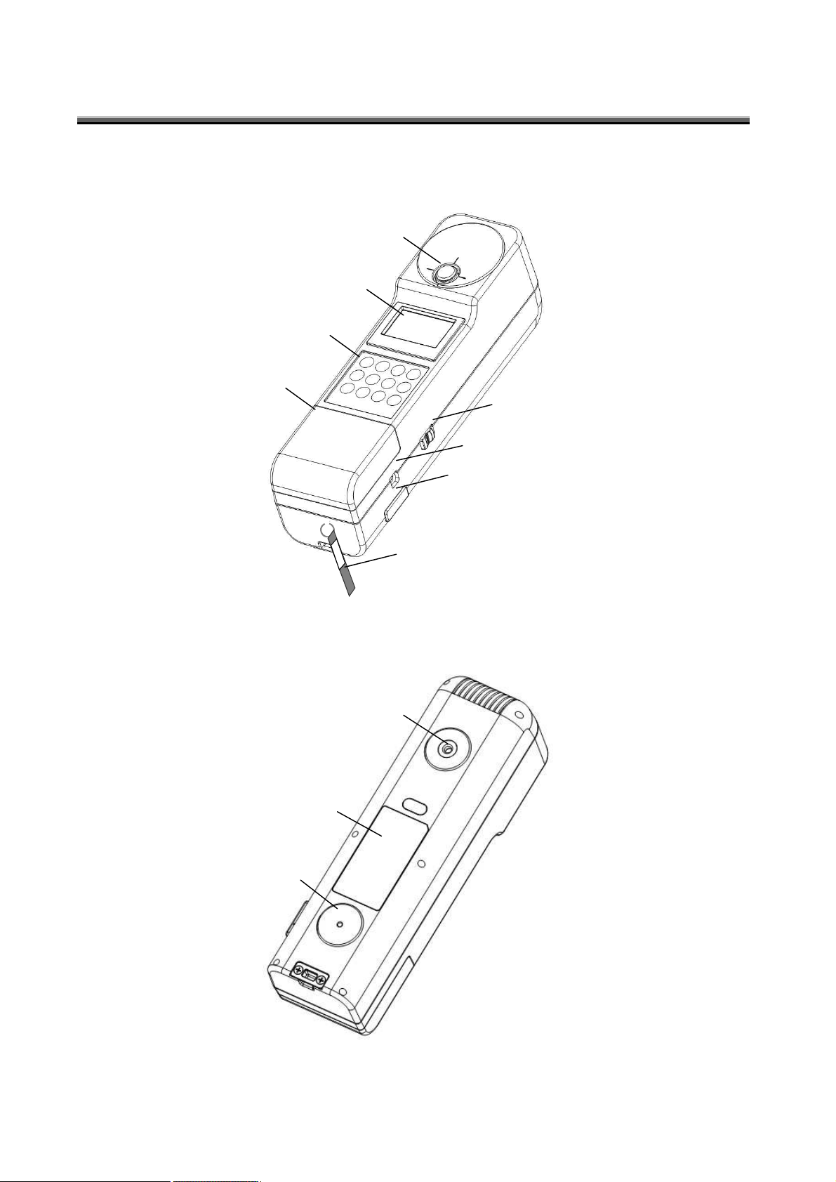
1.2. NAMES AND FUNCTIONS OF COMPONENTS
○1 Beam detector
○2 Display unit
○3 Keyboard
○5 External power supply connector
○4 Power switch
○6 RS-232C connector
○7 Hand strap
Battery cover
○8 Tripod screw
Rating name plate
○9 Tool screw
This chapter will explain the names and functions of the components with the illustrations about the
instrument.
13
Page 14

○1 Beam detector:
Receives the light. Make the whole beam detector receive the light to measure the illuminance.
○2 Display unit:
This is the liquid crystal display unit to indicate a variety of information such as the measured
value or measurement condition.
○3 Keyboard:
These switches are used to start/stop measurement, set the measurement conditions and
perform other operations.
○4 Power switch:
This switch is used to turn on/off the instrument.
○5 External power supply connector:
Insert the output plug of the AC adapter (optional accessory) exclusively for the instrument into
this connector.
○6 RS-232C connector:
Connect the RS-232C cable (standard accessory) exclusively for the instrument to this
connector.
○7 Hand strap:
The falling-off prevention hand strap is attached here.
○8 Tripod screw:
This screw is used to mount the instrument on the tripod.
TOPCON TECHNOHOUSE has adopted the screw for mounting the 1/4-20UNC (depth: 5mm)
camera.
○9 Tool screw:
This screw is used to mount the instrument on a system or others.
The size is “M3×0.5, depth: 6mm”.
14
Page 15
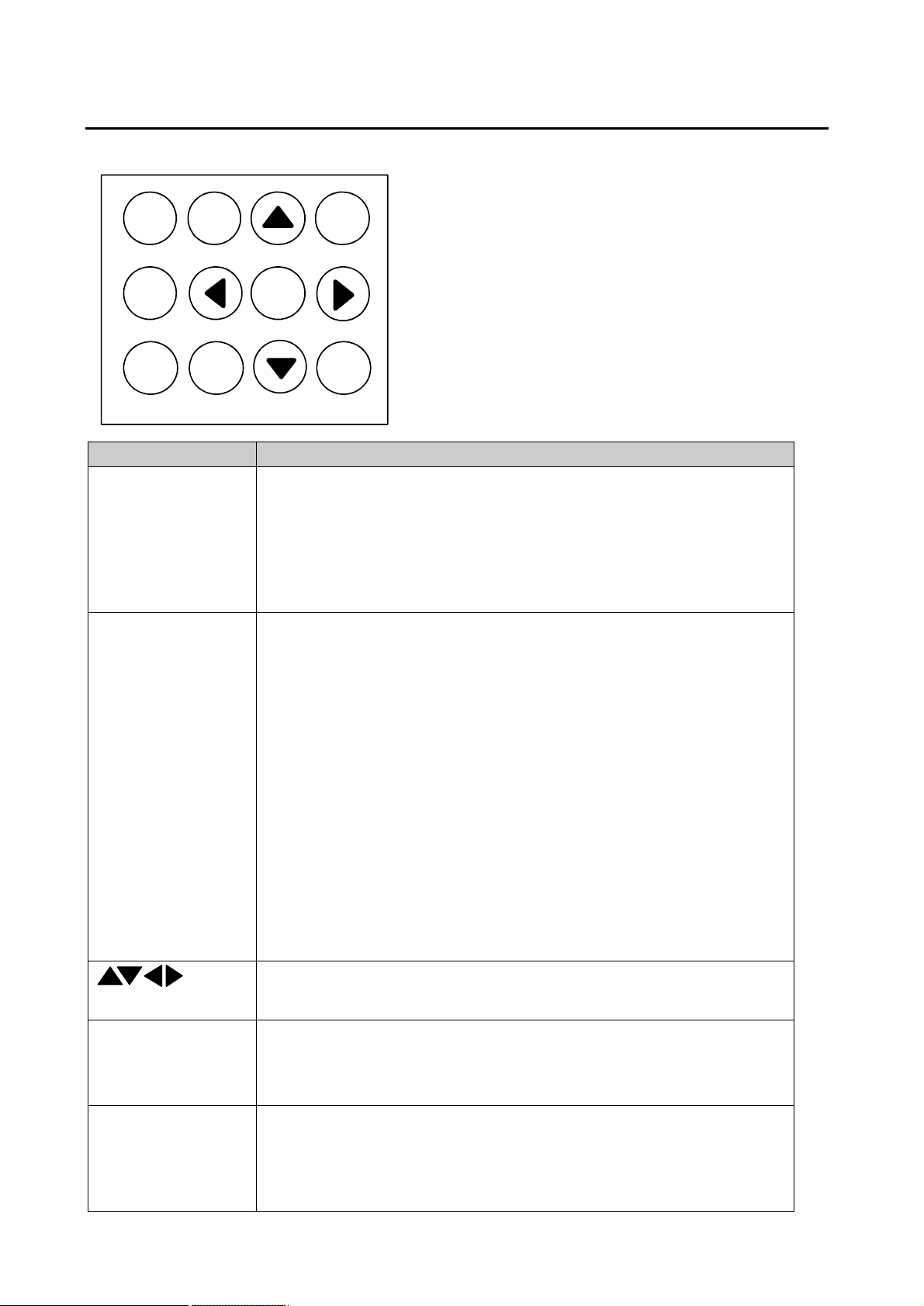
1.2.1. Names and functions of switches on keyboard
Name
Function
MEAS. switch
Starts/stops measurement.
When continuous measurement is valid, measurement starts by
pressing this switch once and stops by pressing it again. To stop
measurement, sometimes the pressing time is longer than usual due to
the integral time.
When continuous measurement is invalid, measurement is performed
once by pressing this switch once.
AUTO/MANU.
switch
Select the measurement range mode.
Each time you press this switch, the mode is changed.
AUTO FULL (FL):
At every measurement, the optimal measurement range and the
integral time are set.
AUTO FIRST (FS):
Only at first measurement, the optimal measurement range and the
integral time are set. The set range and time are kept until the
measurement stops.
AUTO ADJUST (AJ):
When first measurement is done and when “over range” and “under
range” are detected, the optimal measurement range and the integral
time are set.
MANUAL RANGE (ML):
Measurement is done with the measurement range and integral time
set for the “MANUAL” mode.
One of “FL”, “FS”, “AJ” and “ML” is indicated on the display unit.
switches
Used to display the items, the value increment/decrement, the digit shift
and the measurement data history in the function mode.
INV. switch
Used to effectuate the [CALL], [CAL], [WPS] and [W-LAN] functions that
are indicated at the bottom.
When any of these functions is valid, “INV” is indicated on the display
unit.
SAVE. switch
Saves the measurement data of the instrument (up to 50) in the internal
memory. The saved data are not erased even if the power is OFF.
When the measurement data history is saved, the startup time with
“Power: ON” is delayed because the measurement data are read and
internally calculated.
MEAS.
AUTO/
MANU.
INV.
SAVE.
ENTER
MODE
FUNC.
⊿
INV.
CALL
CAL
WPS
W-LAN
The names and functions of switches on the keyboard are mentioned below.
15
Page 16
ENTER switch
This is used to decide the item, value, digit position, etc. in the function
mode.
∆ switch
Measurement is done in the difference mode.
The difference against the reference value is indicated as the
measurement data.
MODE. switch
Select the display mode.
Select one of [Ev/x/y], [Ev/u’/v’], [X/Y/Z], [Ev/Tcp/duv], [Ev/Ra/Tcp],
[Ev/λd/Pe] and [Spectral radiation graph].
You can change “Tcp” of [Ev/Ra/Tcp] to “color rendering property
evaluation” and “special color rendering property evaluation R1-R15”
with [ ] and [ ] switches.
In the color rendering property evaluation mode, the display update is
slower than other modes due to the internal calculation time.
FUNC. switch
The system shifts to the function mode.
In the function mode, set the measurement conditions, the
communication conditions, the correction factor application, etc.
CALL switch
(INV)
Indicates the reference value to be applied to the difference mode.
To return to the normal mode, press [INV.] and then [CALL] again.
CAL switch
(INV)
Unused.
WPS switch
(INV)
You can set and connect the wireless LAN to the WPS device easily.
For applying the WPS function, please read the instruction manual of the
connected device together with this manual.
W-LAN switch
(INV)
Connect the wireless LAN according to the setting conditions.
To disconnect the wireless LAN, press [INV.] and then [W-LAN] again.
16
Page 17
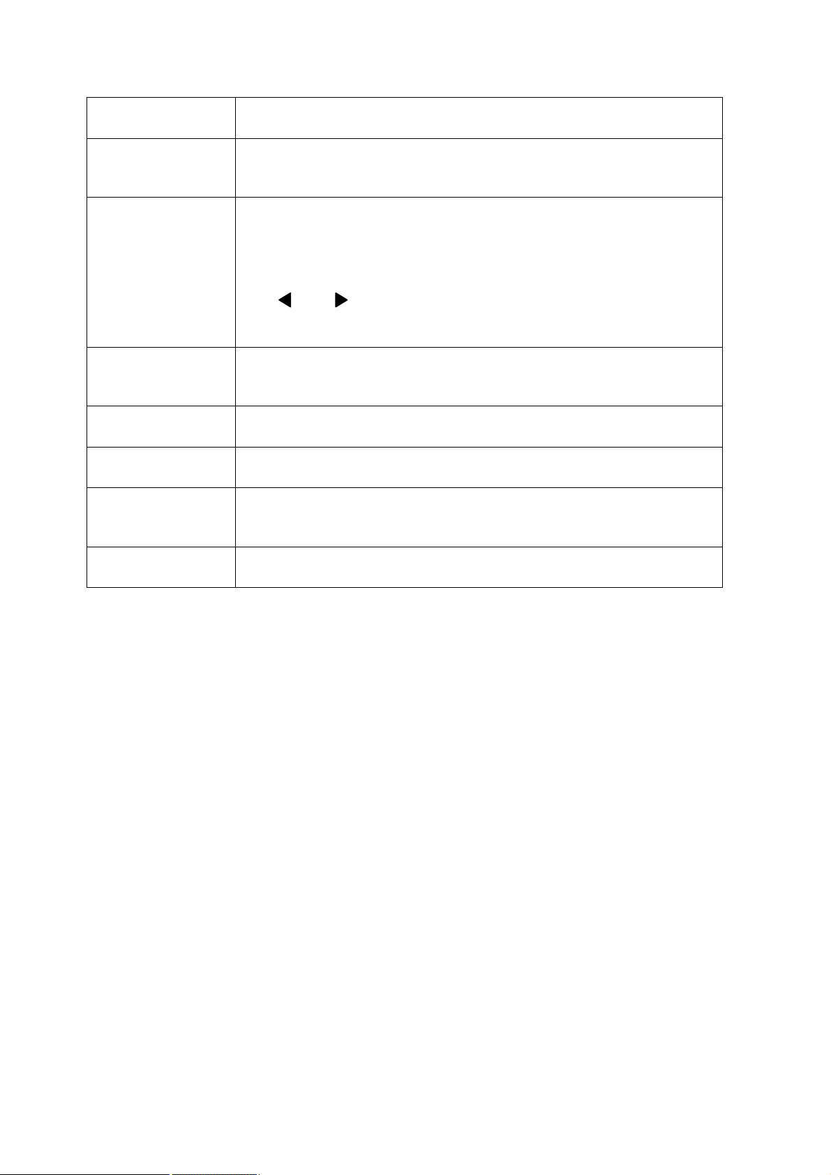
1.2.2. Names and contents of data on the display screen
Name
Contents
○1 Measurement
range mode
Indicates the measurement range mode which is currently set.
FL/FS/AJ/ML
☞
“1.2.1. Names and functions of switches on keyboard”
○2 Average
measurement
Indicates whether average measurement should be done.
SGL : One measurement
AVE : Average measurement
○3 Correction
Indicates whether the correction factor should be applied.
No indication : Correction factor is not applied.
F : Correction factor of spectrum or tristimulus values is
applied.
○4 Interval
measurement
Indicates whether interval measurement should be done.
No indication : Normal measurement
I : Interval measurement
○5 Wireless LAN
Indicates the wireless LAN connection.
No indication : Not connected.
W : Connected.
○6 Battery power
Indicates the remaining power of the driven batteries.
No indication : Power is sufficient.
BAT : Power is not sufficient. (Replace the batteries within 10
minutes.)
Be sure to use the standard accessory, nickel hydride battery. If any
other battery is used, the indication is sometimes different from the
above.
○7 Measurement
status/INV
Indicates the measurement status and the [INV.] ON/OFF status.
No indication: Measurement stops/INV is OFF.
MEAS : Measurement is being performed.
INV : INV is ON.
○8 Measurement
range
Indicates the measurement range.
r1 - r4 : Range 1 to Range 4
○9 Measurement data
Indicates the measurement data according to the display mode.
☞
“1.2.1. Names and functions of switches on keyboard”
○10 Measurement data
history number
Indicates the measurement data history number.
No. 1 - No. 50 (The number of the newest data is No. 1 and the
sequential numbers are given.)
The names and contents of data on the display screen are mentioned below.
17
Page 18
1.3. PREPARATION
WARNING
WARNING
CAUTION
This chapter will explain the preparation before starting measurement.
1.3.1. Connecting the AC adapter
How to connect the AC adapter to the instrument is mentioned below.
Use the AC adapter which is an accessory sold separately.
If not, the AC adapter malfunctions to cause a fire or electric shock.
Remove dust or water from the outlet of the AC adapter.
If not, a fire may occur.
Don’t pull out or insert the plug by a moistened hand.
It may cause an electric shock.
1. Make sure that the instrument is OFF.
18
Page 19

2. Insert the output connector of the AC adapter into the external power supply connector of the
instrument.
3. Insert the AC adapter plug into the outlet.
19
Page 20
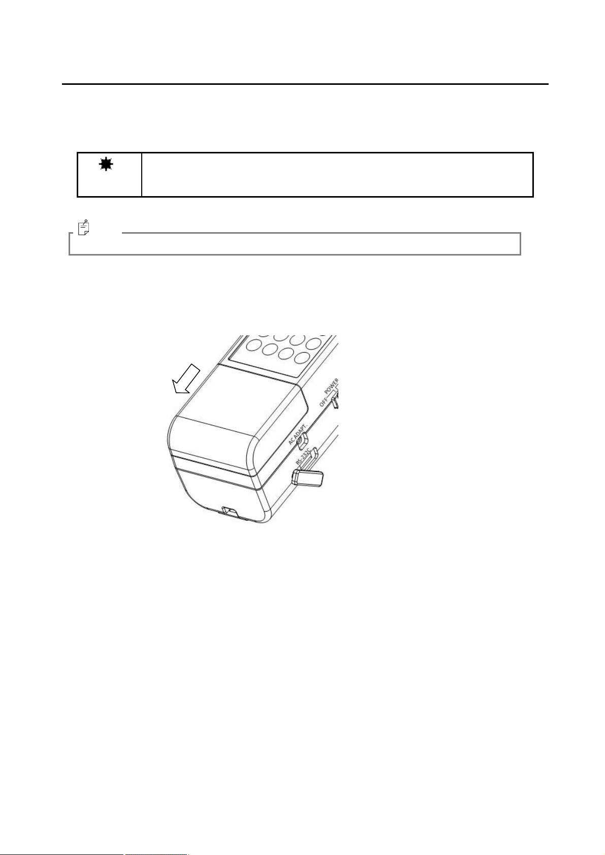
1.3.2. Installing the batteries
NOTICE
Use the standard accessory, nickel hydride battery (charging type). If you use
others except the standard accessory, the instrument may operate irregularly.
MEMO
How to install the batteries is mentioned below.
Use the standard accessory, nickel hydride battery (charging type: 4 pieces).
For charging the nickel hydride battery, refer to the instruction manual of the charger.
1. Make sure that the instrument is OFF.
2. Install the batteries according to the polarity indication in the battery chamber.
3. Attach the battery cover securely.
20
Page 21

1.3.3. Installing personal computer
NOTICE
Don’t connect and disconnect the connectors on condition that the instrument is ON.
NOTICE
The frequency 2.4GHz band, which is used by the instrument, is also used by
electronic ovens, medical instruments and other wireless stations.
1. When using the instrument, check if any other wireless station or wireless
equipment is used in its periphery.
2. If radio wave interference has occurred, change the location of the instrument or
stop using the wireless LAN for the instrument.
3. The wireless LAN module, which conforms to the Japanese technical standards, is
built in the instrument. It is not possible to use the wireless LAN in any other
country or area except Japan.
4. If you use the instrument out of Japan, turn off the wireless LAN function.
☞
“3.2.11. Setting the wireless LAN”
MEMO
MEMO
To connect a personal computer with the instrument, use the RS-232C cable exclusively for the
instrument or the wireless LAN. The RS-232C signal line of the instrument is arranged according to
the 9-pin D-SUB that is used in the DOS/V personal computer and others. When connecting with a
personal computer through the extension cable, use the straight wiring cable.
For the connection on the personal computer, refer to your computer’s manual at the same time.
The RS-232C specifications are shown below. Others except the baud rate are fixed.
• Communication method : Full duplex
• Synchronization : Start-stop transmission
• Baud rate : 9600/19200/38400 bps (Bits Per second)
• Data length : 7 bits
• Parity : Odd number (ODD)
• Stop bit : 1 bit
• Communication type : Text (ASCII)
• Delimite : CR + LF (This is added to the last of a communication data line and
then the data is sent.)
The wireless LAN specifications are shown below. (Exclusively for Japan)
• Standard to be observed : IEEE802.11b infrastructure/ad hoc mode
• Frequency range : 2.4GHz band (1-13ch)
• Communication distance : Indoors 10m/Outdoors 15m typ
• Baud rate : 38400 bps
• Security : WEP/WPA/WPA2
The communication distance and speed are changed due to the radio wave, obstacles,
installation environment, etc. We cannot guarantee the communication speed and distance.
Please understand this.
21
Page 22

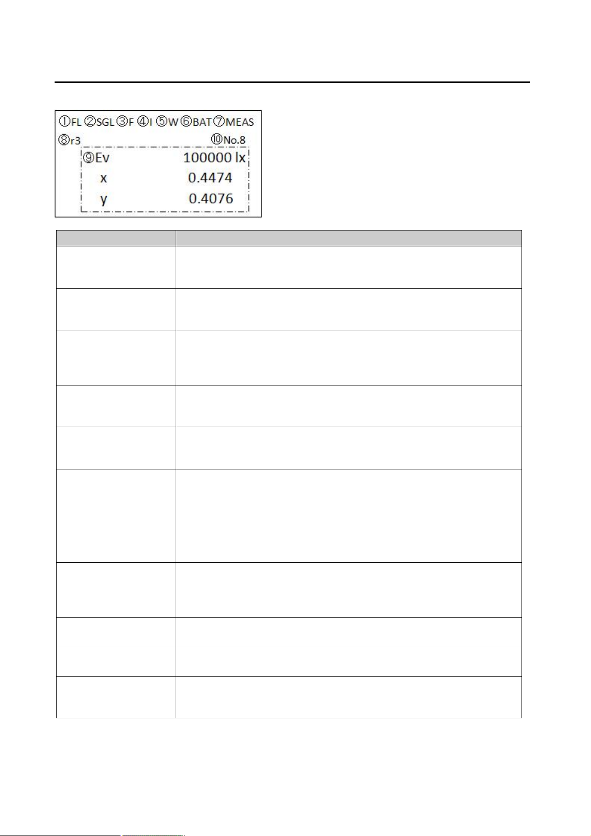
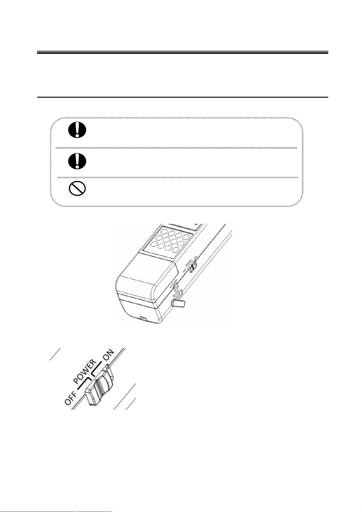
1.3.4. Turning ON/OFF the power
How to turn on/off the power is mentioned below.
n When turning on the power
Slide the power switch to “ON”.
When the power is turned on, initialization starts. If an error occurs during the initialization, the
error message is indicated on the display unit.
n When turning off the power
Slide the power switch to “OFF”.
22
Page 23

Illuminance Ev/Average color rendering property
evaluation Ra/Correlated color temperature mode
Illuminace Ev/Dominant wavelength
λd/Excitation purity Pe mode
MEMO
2.OPERATION OF THE MEASURED VALUE
2.1. DISPLAY OF THE MEASURED VALUE
You can change the measured value display mode by pressing the [MODE] switch when
measurement stops. The changeable display modes are shown below.
Illuminance Ev/Chromaticity xy mode Illuminance Ev/Chromaticity u’v’ mode
Tristimulus values XYZ mode Illuminance Ev/Correlated color temperature
Tcp/Deviation duv mode
Spectral radiation illuminance graph/Peak wavelength
spectral radiation illuminance/Illuminance Ev mode
• [Tcp] can be changed to “Color rendering property evaluation R1-R15”.
• In the difference mode, only illuminance is updated.
23
Page 24

3. SETTING OPERATION
3.1. FUNCTION MODE
Function mode is used to check and change a lot of data and items stored in the built-in memory of the
instrument.
3.1.1. Shifting to function mode/returning to measurement
mode
Use the [FUNC.] switch to shift to the function mode and return to the measurement mode. Press the
[FUNC.] switch once, and the system shifts to the function mode. Press the switch again, and the
system returns to the measurement mode (function mode is canceled).
n Shifting to function mode
1. Make sure that the instrument is in the standby status.
2. Press the [FUNC.] switch to access the function mode.
“3.1.2. Set item/Data display”
☞
n Returning to the measurement mode
Press the [FUNC.] mode again in the function mode. The system exits from the function mode
and returns to the measurement mode.
24
Page 25

3.1.2. Set item/Data display
In the function mode, the displayed items and data are changed by pressing the [ ] and [ ] switches.
The set items and data are shown below.
• Setting the averaging count
• Setting ON/OFF of interval mode
• Setting the interval measurement conditions
• Setting the manual measurement conditions
☞
• Setting ON/OFF of continuous measurement
• Setting the reference light source
• Setting the sample light source
• Setting the reference value
• Setting ON/OFF of the spectral correction factor
• Setting ON/OFF of the tristimulus values correction factor
• Setting ON/OFF of the wireless LAN
• Setting the wireless LAN IP address
• Setting the wireless LAN subnet mask
• Setting the wireless LAN port number
• Setting the wireless LAN access point
• Setting the wireless LAN WEP
• Setting the wireless LAN PASS PHRASE
• Setting the RS-232C baud rate
• Setting the back light
• Setting the measurement data automatic saving function
• Setting the measurement data history clearing function
“3.2.1. Setting the averaging count”
☞
“3.2.2. Setting the interval mode”
☞
“3.2.3. Setting the interval measurement conditions”
☞
“3.2.4. Setting the manual measurement conditions”
“3.2.5. Setting continuous measurement”
☞
“3.2.6. Setting the reference light source”
☞
“3.2.7. Setting the sample light source”
☞
“3.2.8. Setting the reference value”
☞
“3.2.9. Setting the spectral correction”
☞
“3.2.10. Setting the tristimulus values correction”
☞
“3.2.11. Setting the wireless LAN”
☞
“3.2.12. Setting the wireless LAN IP address”
☞
“3.2.13. Setting the wireless LAN subnet mask”
☞
“3.2.14. Setting the wireless LAN port number”
☞
“3.2.15. Setting the wireless LAN access point”
☞
“3.2.16. Setting the wireless LAN WEP”
☞
“3.2.17. Setting the wireless LAN PASS PHRASE”
☞
“3.2.18. Setting the RS-232C baud rate”
☞
“3.2.19. Setting the back light”
☞
“3.2.20. Setting the measurement data automatic saving function”
☞
“3.2.21. Setting the measurement data history clearing function”
☞
25
Page 26

3.2. DETAILS OF FUNCTION MODE
To select a proper item, use the [ ] and [ ] switches. To enter a numerical value, specify the digit
position with the [ ] and [ ] switches and set a value with the [ ] and [ ] switches.
3.2.1. Setting the averaging count
Set the averaging count.
Settable range: 1 - 20
* When “1” is set, the average measurement is invalid.
3.2.2. Setting the interval mode
Set ON/OFF of the interval measurement and the system operation if the interval time is exceeded.
MODE : Set ON/OFF of the interval measurement.
OFF : Invalid
ON : Valid
ERROR STOP : Set whether measurement should continue or stop when the interval time is
exceeded.
OFF : Measurement continues.
ON : Measurement stops.
26
Page 27

3.2.3. Setting the interval measurement conditions
Set the start delay time, the count and the interval time for interval measurement.
START : Set the time until measurement starts since you pressed the [MEAS.] switch.
Settable range: 1 - 180s
COUNT : Set the interval measurement count.
Settable range: 1 - 50
TIME : Set the interval time.
Settable range: 1 - 99s
3.2.4. Setting the manual measurement conditions
Set the measurement range and the integral time for manual measurement.
RANGE : Set the measurement range.
Settable range: 1 - 4
TIME : Set the integral time.
Settable range: 10 - 20000ms
3.2.5. Setting continuous measurement
Set ON/OFF of continuous measurement.
OFF : Measurement is done once and is finished.
ON : Measurement continues until the [MEAS.] switch is pressed again.
27
Page 28

3.2.6. Setting the reference light source
MEMO
Set the type of the reference light that will be applied to the calculation of color rendering property
evaluation.
Settable range : JIS Z 8726/Illuminant A/Illuminant D65/Illuminant D50/Illuminant D55/Illuminant
D75/Illuminant C
3.2.7. Setting the sample light source
Set the sample light source that will be applied to the calculation of color rendering property evaluation.
Daylight : Daylight fluorescent lamp
Other Lamp : Others except daylight fluorescent lamp
3.2.8. Setting the reference value
Set the reference value that will be applied to the difference mode.
STD SELECT : Set the reference value registration number.
Settable range: 1 - 3
The setting procedure is shown below.
1. Press the [ENTER] switch and select a registration number with the [ ] and [ ] switches.
2. After selecting, press the [MEAS.] switch to perform measurement.
3. After the measurement, its result is indicated. Press the [ENTER] switch to register the result.
The reference value of the indicated number is applied.
28
Page 29

3.2.9. Setting the spectral correction
MEMO
Set whether the correction factor of each wavelength should be applied to the spectral radiation
illuminance.
Enter the correction factor directly or set it within 380nm - 780nm at intervals of 1nm through the
remote mode.
OFF : Spectral correction is not applied.
ON : Spectral correction is applied.
Shift to the direct entry screen for the correction factor of each wavelength. You can
change the wavelength with the [ ] and [ ] switches. If you do not enter the correction
factor directly, press the [FUNC.] switch.
Settable range: 0.0001 - 100.0
You can set the correction factor from the colorimetry program CS-900A.
3.2.10. Setting the tristimulus values correction
Set the correction factor and whether it should be applied to the tristimulus values.
OFF : Tristimulus values correction is not applied.
ON : Tristimulus values correction is applied.
Settable range: 0.0001 - 100.0
29
Page 30
3.2.11. Setting the wireless LAN
MEMO
MEMO
Set ON/OFF of the wireless LAN function.
• This menu is indicated only in the model having the wireless LAN function.
• After changing the setting, turn on/off the power of the instrument. By turning it on/off, the set
data is applied.
• If the instrument is used in other countries except Japan, be sure to set “OFF” for wireless
LAN function.
3.2.12. Setting the wireless LAN IP address
Set the instrument’s IP address that will be applied to the wireless LAN communication.
Settable range : 192.168.0.0 - 192.168.255.255
• This menu is indicated only in the model having the wireless LAN function.
• After changing the setting, turn on/off the power of the instrument. By turning it on/off, the set
data is applied.
30
Page 31

3.2.13. Setting the wireless LAN subnet mask
MEMO
MEMO
Set the instrument’s subnet mask that will be applied to the wireless LAN communication.
Settable range : 255.255.0.0. - 255.255.255.255
• This menu is indicated only in the model having the wireless LAN function.
• After changing the setting, turn on/off the power of the instrument. By turning it on/off, the set
data is applied.
3.2.14. Setting the wireless LAN port number
Set the instrument’s port number that will be applied to the wireless LAN communication.
Settable range : 49152 - 65535
• This menu is indicated only in the model having the wireless LAN function.
• After changing the setting, turn on/off the power of the instrument. By turning it on/off, the set
data is applied.
31
Page 32

3.2.15. Setting the wireless LAN access point
MEMO
MEMO
Set the access point (SSID) that will be applied to the wireless LAN communication.
Press the [ENTER] switch, and the access points, which can be connected currently, are indicated.
Select and decide a proper access point.
• For setting the access point, read the instruction manual of the connected device at the same
time.
• If the access point is not changed, it is not necessary to set it at each measurement. Set the
access point only when it must be changed.
• This menu is indicated only in the model having the wireless LAN function.
• After changing the setting, turn on/off the power of the instrument. By turning it on/off, the set
data is applied.
3.2.16. Setting the wireless LAN WEP
Set WEP (Wired Equivalent Privacy Key) that will be applied to the wireless LAN communication.
• For setting WEP, read the instruction manual of the connected device at the same time.
• This menu is indicated only in the model having the wireless LAN function.
• After changing the setting, turn on/off the power of the instrument. By turning it on/off, the set
data is applied.
32
Page 33

3.2.17. Setting the wireless LAN PASS PHRASE
MEMO
MEMO
Set PASS PHRASE that will be applied to the wireless LAN communication.
Settable range : 63 letters or less
• For setting PASS PHRASE, read the instruction manual of the connected device at the same
time.
• This menu is indicated only in the model having the wireless LAN function.
• After changing the setting, turn on/off the power of the instrument. By turning it on/off, the set
data is applied.
3.2.18. Setting the RS-232C baud rate
Set the baud rate that will be applied to the RS-232C communication.
Settable range: 38400/19200/9600
After changing the setting, turn on/off the power of the instrument. By turning it on/off, the set
data is applied.
33
Page 34

3.2.19. Setting the back light
MEMO
MEMO
Set ON/OFF of the back light in the liquid crystal display unit.
OFF : The back light is always OFF.
ON : The back light is always ON.
ECO : When measurement is being done and when the instrument is not operated for 1 minute or
more, the back light is OFF.
Right after measurement has been finished and when any switch is pressed, the back light
is ON.
If turning on the back light only is necessary in the [ECO] mode, press the [ENTER] switch.
3.2.20. Setting the measurement data automatic saving function
Set ON/OFF of the measurement data automatic saving function.
OFF : The data is not automatically saved.
ON : The data is automatically saved at each measurement.
When the automatic saving function is ON, the data is written in the internal memory at each
measurement. So it takes longer time until the measurement is finished.
3.2.21. Setting the measurement data history clearing function
Clear the history of all the measurement data that are saved in the instrument’s internal memory.
YES : Clear the history of all the measurement data.
BACK : Cancels the function mode.
34
Page 35

Communication command
Function
RM
Set the remote mode.
LM
Set the local mode. (The remote mode is canceled.)
WHO
Obtain the model name.
VER
Obtain the software version.
SRL
Obtain the serial number.
ST
Execute measurement.
When measurement is finished, the measurement data is sent
back.
All the measurement data are sent back.
☞
“4.4 MEASUREMENT DATA OUTPUT FORMAT”
ST2
Execute measurement.
When measurement is finished, the measurement data is sent
back.
Only colorimetry data is sent back.
☞
“4.4 MEASUREMENT DATA OUTPUT FORMAT”
ST3
Execute measurement.
When measurement is finished, the measurement data is sent
back.
Only the colorimetry data and color rendering property evaluation
are sent back.
☞
“4.4 MEASUREMENT DATA OUTPUT FORMAT”
4. COMMUNICATION WITH PERSONAL
COMPUTER
4.1. COMMUNICATION COMMAND
The instrument (IM-1000) can communicate with a personal computer by using RS-232C and wireless
LAN.
This chapter will explain the commands that will be used when the customer makes a peculiar
program for the communication with the instrument.
* The values are fixed for the following items.
Data bit: 7
Stop bit: 1
Parity: Odd number (ODD)
Delimiter: CR: 0x0d, LF: 0x0a
Use the RS-232C communication cable exclusively for the instrument.
4.2. COMMAND LIST
The communication commands and their functions are shown below. “_” means a space and “#”
means a numerical value.
35
Page 36

Communication command
Function
CST
Start continuous measurement.
The data of each measurement is not sent back. Obtain the
measurement data with the “STR*” command.
If you send this command during continuous measurement, “NO” is
returned.
STP
Stop continuous measurement.
If you send this command during continuous measurement,
continuous measurement stops.
STR_#
- Obtain the data of the specified number from the measurement
history while measurement is in the stop status.
Settable range: 1 - 50 (“1” is the newest data.)
- Obtain the newest data during continuous measurement. It is
not necessary to specify the measurement history number.
Send the “STR” command only.
Obtain all the measurement data.
☞
“4.4 MEASUREMENT DATA OUTPUT FORMAT”
STR2_#
- Obtain the data of the specified number from the measurement
history while measurement is in the stop status.
Settable range: 1 - 50 (“1” is the newest data.)
- Obtain the newest data during continuous measurement. It is
not necessary to specify the measurement history number.
Send the “STR2” command only.
Obtain the colorimetry data only. You cannot obtain the spectral
radiation illuminance and color rendering property evaluation.
☞
“4.4 MEASUREMENT DATA OUTPUT FORMAT”
STR3_#
- Obtain the data of the specified number from the measurement
history while measurement is in the stop status.
Settable range: 1 - 50 (“1” is the newest data.)
- Obtain the newest data during continuous measurement. It is
not necessary to specify the measurement history number.
Send the “STR3” command only.
Obtain the colorimetry data and color rendering property evaluation.
You cannot obtain the spectral radiation illuminance.
☞
“4.4 MEASUREMENT DATA OUTPUT FORMAT”
MG_#
Set the measurement range mode.
0: AUTO FULL (FL) 1: AUTO FIRST (FS)
2: AUTO ADJUST (AJ) 3: MANUAL RANGE (ML)
☞
“1.2.1. Names and functions of switches on keyboard”
MRW_#
Set the measurement range when [MANUAL RANGE] is set.
1: Range 1 2: Range 2 3: Range 3 4: Range 4
MRR
Obtain the measurement range when [MANUAL RANGE] is set.
MTW_##
Set the integral time when [MANUAL RANGE] is set.
Settable range: 10 - 20000ms
MTR
Obtain the integral time when [MANUAL RANGE] is set.
FO_#
Set ON/OFF of spectral correction.
0: OFF 1: ON
FOR
Obtain the ON/OFF data of spectral correction.
36
Page 37

Communication command
Function
FW_#_#######
Set the spectral correction factor (within 380 - 780nm at intervals of
1nm).
0: 380nm - 400: 780nm
Settable range: 0.0001 - 100.0
FR_#
Obtain the spectral correction factor (within 380 - 780nm at
intervals of 1nm).
0: 380nm - 400: 780nm
TRW_#
Set ON/OFF of the tristimulus values.
0: OFF 1: ON
TRR
Obtain the ON/OFF data of tristimulus values.
XW_#######
Set the correction factor of the tristimulus value X.
Settable range: 0.0001 - 100.0
XR
Obtain the correction factor of the tristimulus value X.
YW_#######
Set the correction factor of the tristimulus value Y.
Settable range: 0.0001 - 100.0
YR
Obtain the correction factor of the tristimulus value Y.
ZW_#######
Set the correction factor of the tristimulus value Z.
Settable range: 0.0001 - 100.0
ZR
Obtain the correction factor of the tristimulus value Z.
BRW_#
Set the baud rate of RS-232C.
0: 9600 1: 19200 2: 38400
BRR
Obtain the baud rate of RS-232C.
ACW_##
Set the averaging count.
Settable range: 1 - 20
When “1” is set, the average measurement is invalid.
ACR
Obtain the averaging count in average measurement.
ERR
Obtain the newest error number and message.
37
Page 38

4.3. COMMUNICATION PROTOCOL
MEMO
The protocols for the RS-232C/wireless LAN communication are shown below.
The instrument (IM-1000) sends the following answers as the responses to all the commands.
• “OK” when the command is normally received
• “NO” when the command cannot be analyzed
• “NG” when the command is normally received but the processing is not normal
“_” means a space and “#” means a numerical value.
When sending the commands continuously, set an interval of at least 3ms between the
sending actions.
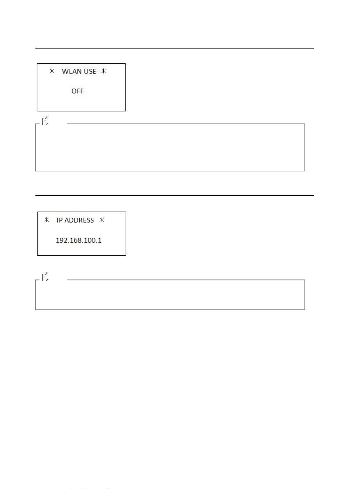
4.3.1. RM command
Set the remote mode.
External control device
“RM”+CR+LF
Command IM-1000
“OK”+CR+LF
4.3.2. LM command
Set the local mode.
When the instrument receives this command while the local mode is set, it sends back “NO”.
External control device Command IM -1000
“LM”+CR+LF
“OK”+CR+LF
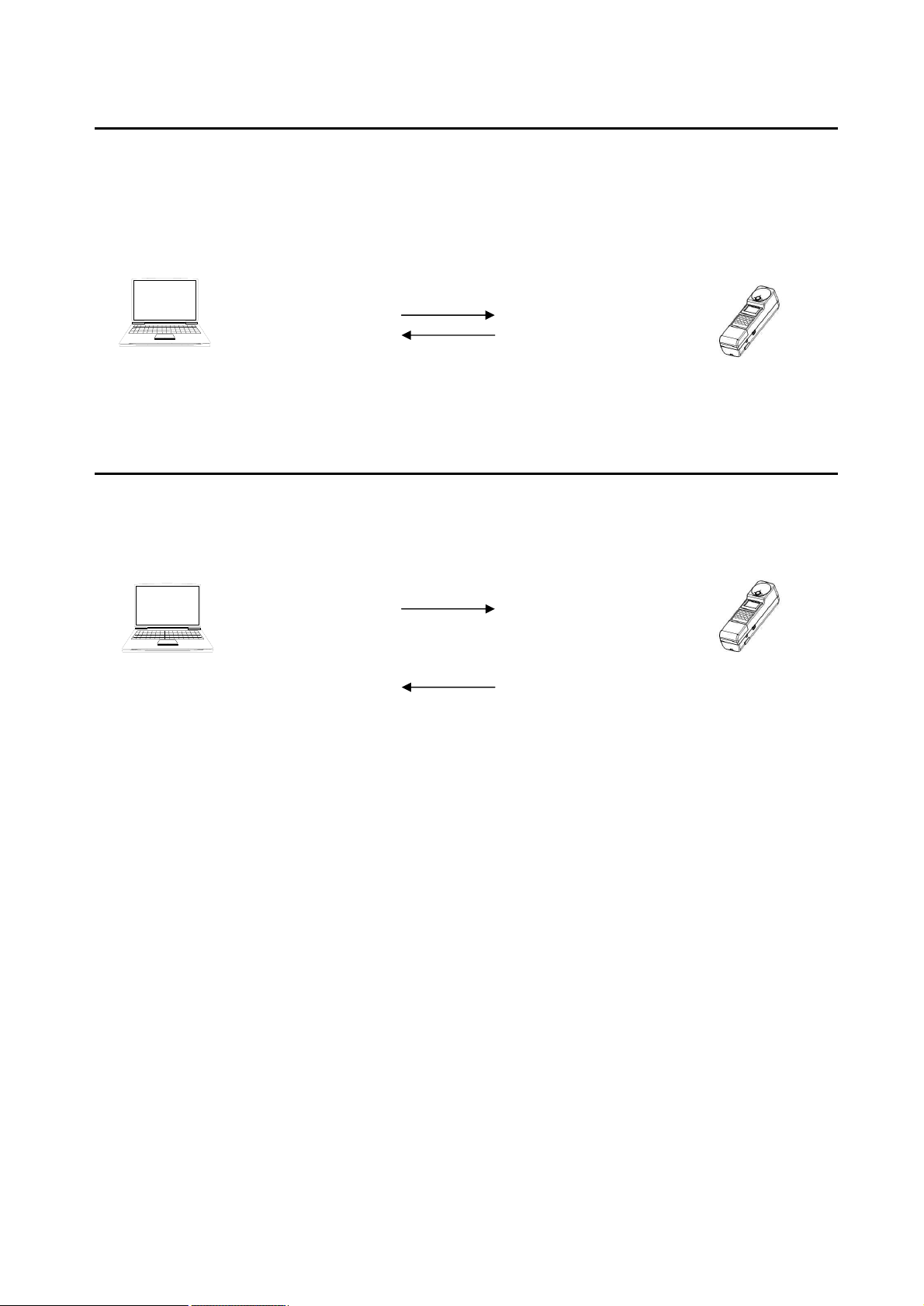
4.3.3. WHO command
Obtain a model name.
External control device Command IM -1000
“WHO”+CR+LF
“OK”+CR+LF
“IM-1000”+CR+LF
“END”+CR+LF
38
Page 39

4.3.4. VER command
Obtain the software version.
Obtainable range: 1.00 - 99.99
External con trol device Command IM -1000
“VER”+CR+LF
4.3.5. SRL command
Obtain the serial number.
Obtainable range: 00000000 - 99999999
External control device Command IM -1000
“SRL”+CR+LF
“OK”+CR+LF
“1.00”+CR+LF
“END”+CR+LF
“OK”+CR+LF
“12345678”+CR+LF
“END”+CR+LF
39
Page 40

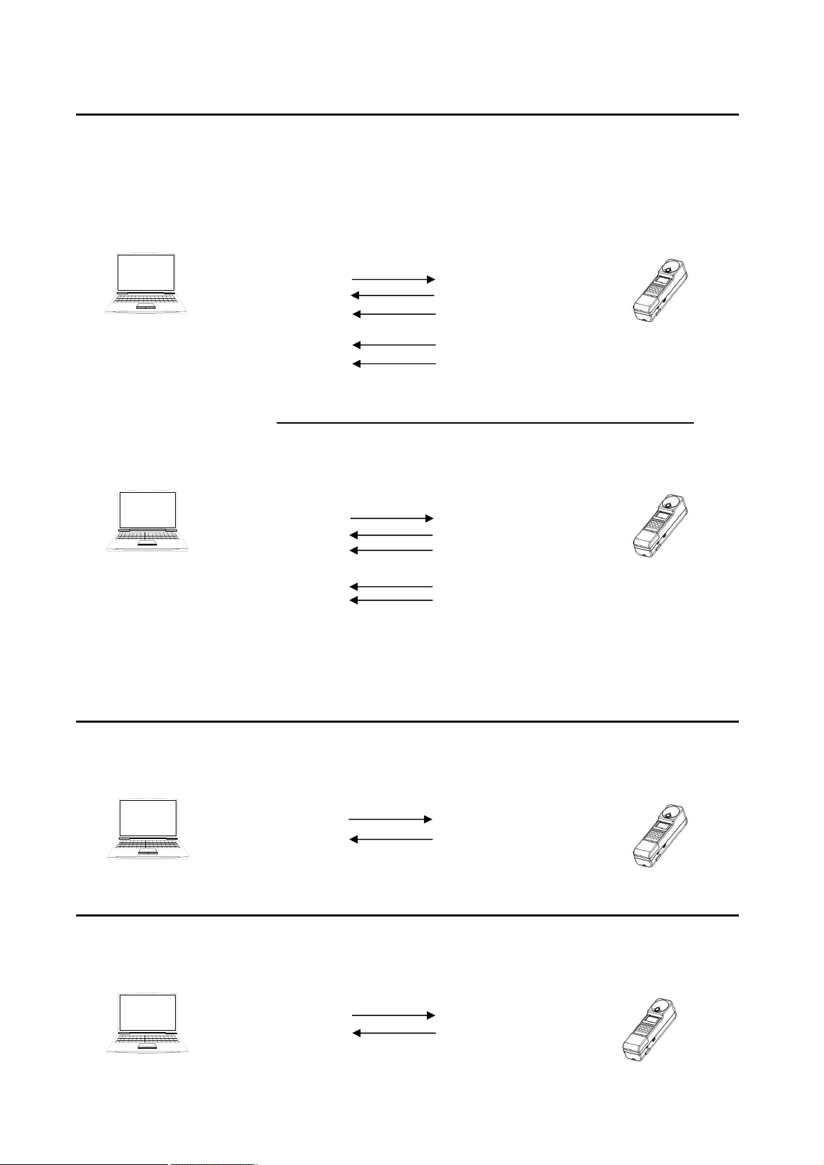
4.3.6. ST command
As soon as the instrument receives this command, it starts measurement according to the
measurement conditions already set. When the measurement is finished, the measurement data is
sent according to “4.4. MEASUREMENT DATA OUTPUT FORMAT”.
- Sending from the external control device to the instrument
The external control device (PC or PLC, etc.) sends the character line “ST” (0x53/0x54) with CR
(0x0d) and LF (0X0a) via RS-232C or wireless LAN.
- Sending from the instrument to the external control device
The instrument recognizes “ST” and sends back “OK” with CR and LF as the command recognition
normal response. At the same time measurement starts.
When the measurement is normally finished, the measurement data is sent back according to “n ST,
STR command measurement data format” of “4.4 MEASUREMENT DATA OUTPUT FORMAT”. If an
error occurs during measurement, “NG” with CR and LF is sent back. When the external control
device receives “NG”, it sends “ERR” with CR and LF and you can check the contents of the error.
External control device Command IM -1000
“ST”+CR+LF
“OK”+CR+LF
Measurement starts.
・ ・ ・ ・ ・
Measurement is finished.
DATA1+CR+LF
・ ・ ・ ・ ・
DATA433+CR+LF
“END”+CR+LF
n When the command cannot be recognized
“ST”+CR+LF
“NO”+CR+LF
n When a measurement error occurs
“ST”+CR+LF
“OK”+CR+LF
Measurement starts.
・ ・ ・ ・ ・
“NG”+CR+LF
* All the data (colorimetry, spectral radiation illuminance and color rendering property evaluation) are
output.
40
Page 41

4.3.7. ST2 command
As soon as the instrument receives this command, it starts measurement according to the
measurement conditions already set. When the measurement is finished, the measurement data is
sent back according to “n ST2, STR2 command measurement data format” of “4.4. MEASUREMENT
DATA OUTPUT FORMAT”.
External control device Command IM -1000
“ST2”+CR+LF
“OK”+CR+LF
Measurement starts.
・ ・ ・ ・ ・
Measurement is finished.
DATA1+CR+LF
・ ・ ・ ・ ・
DATA16+CR+LF
* Only the colorimetry is output. The spectral radiation illuminance and color rendering property
evaluation are not output.
“END”+CR+LF
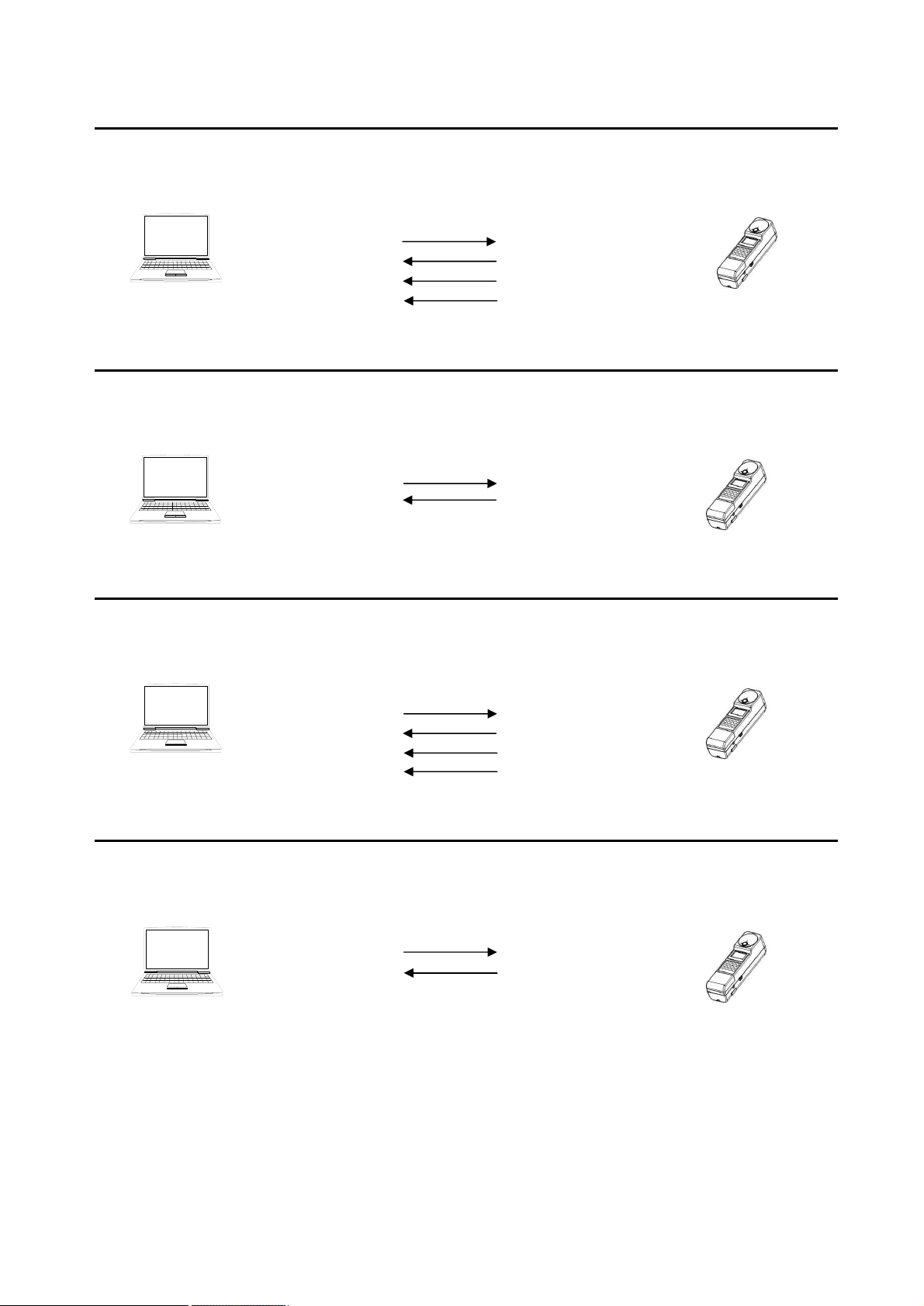
4.3.8. ST3 command
As soon as the instrument receives this command, it starts measurement according to the
measurement conditions already set. When the measurement is normally finished, the measurement
data is sent back according to “n ST3, STR3 command measurement data format” of “4.4.
MEASUREMENT DATA OUTPUT FORMAT”.
External control device Command IM -1000
“ST3”+CR+LF
“OK”+CR+LF
Measurement starts.
・ ・ ・ ・ ・
Measurement is finished.
DATA1+CR+LF
・ ・ ・ ・ ・
DATA32+CR+LF
* Only the colorimetry and color rendering property evaluation are output. The spectral radiation
illuminance is not output.
“END”+CR+LF
41
Page 42
4.3.9. CST command
When the instrument receives this command while measurement is in the stop status, it starts
continuous measurement at once according to the measurement conditions already set. The data of
each measurement is not sent back. Obtain the measurement data with the “STR”, “STR2” and
“STR3” commands.
When the instrument receives this command during continuous measurement, it sends back “NO”.
External control device Command IM -1000
“CST”+CR+LF
“OK”+CR+LF
Continuous
measurement starts.
・ ・ ・ ・ ・
4.3.10. STP command
When the instrument receives this command during continuous measurement, it stops the continuous
measurement. Sometimes it takes long time until the measurement stops due to the receiving time
status.
External control de vice Command IM -1000
“STP”+CR+LF
Continuous
measurement stops.
・ ・ ・ ・ ・
“OK”+CR+LF
42
Page 43

4.3.11. STR_# command
When the instrument receives this command while measurement is in the stop status, the specified
number data saved in the instrument is output. The measurement data number is “No.1” (newest) to
“No.50”.
Obtainable range: 1 (newest) - 50
n When measurement is in the stop status
External control device Command IM -1000
“STR_#”+CR+LF
“OK”+CR+LF
DATA1+CR+LF
・ ・ ・ ・ ・
DATA433+CR+LF
“END”+CR+LF
When the instrument receives this command during continuous measurement, the newest
measurement data is output. It is not necessary to specify the measurement data number.
n When the instrument is performing measurement continuously
External contr ol device Command IM -1000
“STR”+CR+LF
“OK”+CR+LF
DATA1+CR+LF
・ ・ ・ ・ ・
DATA433+CR+LF
“END”+CR+LF
* All the data (colorimetry, spectral radiation illuminance and color rendering property evaluation) are
output.
43
Page 44

4.3.12. STR2_# command
When the instrument receives this command while measurement is in the stop status, the specified
number data saved in the instrument is output. The measurement data number is “No.1” (newest) to
“No.50”.
Obtainable range: 1 (newest) - 50
n When measurement is in the stop status
External control device Command IM -1000
“STR2_#”+CR+LF
“OK”+CR+LF
DATA1+CR+LF
・ ・ ・ ・ ・
DATA16+CR+LF
“END”+CR+LF
When the instrument receives this command during continuous measurement, the newest
measurement data is output. It is not necessary to specify the measurement data number.
n When the instrument is performing measurement continuously
External control device Command IM -1000
“STR2”+CR+LF
“OK”+CR+LF
DATA1+CR+LF
・ ・ ・ ・ ・
DATA16+CR+LF
“END”+CR+LF
* Only the colorimetry is output. The spectral radiation illuminance and color rendering property
evaluation are not output.
44
Page 45
4.3.13. STR3_# command
When the instrument receives this command while measurement is in the stop status, the specified
number data saved in the instrument is output. The measurement data number is “No.1” (newest) to
“No.50”.
Obtainable range: 1 (newest) - 50
n When measurement is in the stop status
External control device Command IM -1000
“STR3_#”+CR+LF
“OK”+CR+LF
DATA1+CR+LF
・ ・ ・ ・ ・
DATA32+CR+LF
When the instrument receives this command during continuous measurement, the newest
measurement data is output. It is not necessary to specify the measurement data number.
n When the instrument is performing measurement continuously
External control device Command IM -1000
“STR3”+CR+LF
* Only the colorimetry and color rendering property evaluation are output. The spectral radiation
illuminance is not output.
“END”+CR+LF
“OK”+CR+LF
DATA1+CR+LF
・ ・ ・ ・ ・
DATA32+CR+LF
“END”+CR+LF
4.3.14. MG_# command
Set the measurement range mode.
Settable range 0: AUTO FULL 1: AUTO FIRST 2: AUTO ADJUST 3: MANUAL RANGE
External control device Command IM -1000
“MG_#”+CR+LF
“OK”+CR+LF
3.3.15. MRW_# command
Set the measurement range for the “MANUAL RANGE” measurement.
Settable range 1: Range 1 2: Range 2 3: Range 3 4: Range 4
External control device Command IM -1000
“MRW_####”+CR+LF
“OK”+CR+LF
45
Page 46
4.3.16. MRR command
Obtain the measurement range for the “MANUAL RANGE” measurement.
Obtainable range 1: Range 1 2: Range 2 3: Range 3 4: Range 4
External control device Command IM -1000
“MRR”+CR+LF
“OK”+CR+LF
“1”+CR+LF
“END”+CR+LF
4.3.17. MTW_## command
Set the integral time for the “MANUAL RANGE” measurement.
Settable range: 10 - 20000ms
External control device Command IM -1000
“MTW_##”+CR+LF
“OK”+CR+LF
4.3.18. MTR command
Obtain the integral time for the “MANUAL RANGE” measurement.
Obtainable range: 10 - 20000ms
External control device Command IM -1000
“MTR”+CR+LF
“OK”+CR+LF
“####”+CR+LF
“END”+CR+LF
4.3.19. FO_# command
Set ON/OFF of the spectral correction factor.
Settable range 0: OFF 1: ON
External control device Command IM -1000
“FO_#”+CR+LF
“OK”+CR+LF
46
Page 47

4.3.20. FOR command
Obtain the ON/OFF data of the spectral correction factor.
Obtainable range 0: OFF 1: ON
External control device Command IM -1000
“FOR”+CR+LF
4.3.21. FW_##_#### command
Set the spectral correction factor at intervals of 1nm.
Settable range 1: 0:380nm - 400:780nm
Settable range 2: 0.0001 - 100.0
External control device Command IM -1000
“FW_##_####”+CR+LF
“OK”+CR+LF
“#”+CR+LF
“END”+CR+LF
“OK”+CR+LF
4.3.22. FR_## command
Obtain the spectral correction factor at intervals of 1nm.
Obtainable range: 0:380nm - 400:780nm
External control device Command IM -1000
“FR_##”+CR+LF
4.3.23. TRW_# command
Set ON/OFF of the tristimulus values correction factor.
Settable range 0: OFF 1: ON
External control device Command IM -1000
“TRW_#”+CR+LF
“OK”+CR+LF
“####”+CR+LF
“END”+CR+LF
“OK”+CR+LF
47
Page 48

4.3.24. TRR command
Obtain the ON/OFF data of the tristimulus values correction factor.
Obtainable range 0: OFF 1: ON
External control device Command IM -1000
“TRR”+CR+LF
“OK”+CR+LF
“#”+CR+LF
“END”+CR+LF
4.3.25. XW, YW, ZW_##_#### command
Set the correction factors of the tristimulus values XYZ.
Settable range: 0.0001 - 100.0
External control device Command IM -1000
“FY_####”+CR+LF
“OK”+CR+LF
4.3.26. XR, YR, ZR command
Obtain the correction factors of the tristimulus values XYZ.
Obtainable range: 0.0001 - 100.0
External control device Command IM -1000
“XR”+CR+LF
4.3.27. BRW _# command
Set the baud rate for the RS-232C communication.
Settable range 0: 9600 1: 19200 2: 38400
External control device Command IM -1000
“BRW_#”+CR+LF
“OK”+CR+LF
“####”+CR+LF
“END”+CR+LF
“OK”+CR+LF
48
Page 49

4.3.28. BRR command
Obtain the baud rate for the RS-232C communication.
Obtainable range 0: 9600 1: 19200 2: 38400
External control device Command IM -100 0
“BRR”+CR+LF
4.3.29. ACW_## command
Set the averaging count.
Settable range: 1 - 20
External control device Command IM -1000
“ACW_##”+CR+LF
“OK”+CR+LF
“#”+CR+LF
“END”+CR+LF
“OK”+CR+LF
4.3.30. ACR command
Obtain the averaging count.
Obtainable range: 1 - 20
External control device Command IM -1000
“ACR”+CR+LF
4.3.31. ERR command
Obtain the newest error number and message.
Obtainable range 1: 0 - 999
Obtainable range 2: Maximum 20 bytes
External con trol device Command IM -1000
“ERR”+CR+LF
“OK”+CR+LF
“##”+CR+LF
“END”+CR+LF
“OK”+CR+LF
“12”+CR+LF
“over range error”+CR+LF
“END”+CR+LF
49
Page 50

4.4. MEASUREMENT DATA OUTPUT FORMAT
No.
Item
Unit
Example of output
Remarks
1
Measurement range
- 1
2
Integral time
ms
150
Unit: 1ms
3
Radiant illuminance
W/m2
2.495E-05
Valid digit of index: 4 digits
4
Illuminance
lx
143.5
Valid digit: Upper 4 digits
In the case of 999 or less, the
numeral at the first decimal
place is indicated.
5
Tristimulus value X
-
144.1
¯
6
Tristimulus value Y
-
143.5
¯
7
Tristimulus value Z
-
83.1
¯
8
Chromaticity x
-
0.3885
To the fourth decimal place
9
Chromaticity y
-
0.3872
¯
10
Chromaticity u’
-
0.2262
¯
11
Chromaticity v’
-
0.5073
¯
12
Correlated color
temperature
K
3868
13
Deviation
-
0.0026
To the fourth decimal place
14
Dominant wavelength
nm
578.3
To the first decimal place
15
Excitation purity
-
0.3281
To the fourth decimal place
16
Peak wavelength
nm
555
17
Spectral radiation
illuminance 380nm
W/m3
2.495E-04
Valid digit of index: 4 digits
¯
¯
¯
¯
¯
417
Spectral radiation
illuminance 780nm
W/m3
1.736E-02
¯
418
Average color rendering
property evaluation Ra
-
89
419
Color rendering property
evaluation R1
-
76
¯
¯
¯
¯
¯
Color rendering property
evaluation R8
-
98
¯
Special color rendering
property evaluation R9
-
84
¯
¯
¯
¯
433
Special color rendering
property evaluation R15
-
64
434
Data end
-
“END”
End command
The formats to output the measurement data from the instrument are shown below.
The measurement data format is changed according to the measurement commands and the
measurement data obtaining commands.
n ST, STR command measurement data format
* 434 items are fixed for output. If the measured value is not normal, “****” is output for the item.
50
Page 51

n ST2, STR2 command measurement data format
No.
Item
Unit
Example of output
Remarks
1
Measurement range
- 1
2
Integral time
ms
150
Unit: 1ms
3
Radiant illuminance
W/m2
2.495E-05
Valid digit of index: 4 digits
4
Illuminance
lx
143.5
Valid digit: Upper 4 digits
In the case of 999 or less, the
numeral at the first decimal
place is indicated.
5
Tristimulus value X
-
144.1
¯
6
Tristimulus value Y
-
143.5
¯
7
Tristimulus value Z
-
83.1
¯
8
Chromaticity x
-
0.3885
To the fourth decimal place
9
Chromaticity y
-
0.3872
¯
10
Chromaticity u’
-
0.2262
¯
11
Chromaticity v’
-
0.5073
¯
12
Correlated color
temperature
K
3868
13
Deviation
-
0.0026
To the fourth decimal place
14
Dominant wavelength
nm
578.3
To the first decimal place
15
Excitation purity
-
0.3281
To the fourth decimal place
16
Peak wavelength
nm
555
17
Data end
-
“END”
End command
* 17 items are fixed for output. If the measured value is not normal, “****” is output for the item.
51
Page 52

n ST3, STR3 command measurement data format
No.
Item
Unit
Example of output
Remarks
1
Measurement range
- 1
2
Integral time
ms
150
Unit: 1ms
3
Radiant illuminance
W/m2
2.495E-05
Valid digit of index: 4 digits
4
Illuminance
lx
143.5
Valid digit: Upper 4 digits
In the case of 999 or less, the
numeral at the first decimal
place is indicated.
5
Tristimulus value X
-
144.1
¯
6
Tristimulus value Y
-
143.5
¯
7
Tristimulus value Z
-
83.1
¯
8
Chromaticity x
-
0.3885
To the fourth decimal place
9
Chromaticity y
-
0.3872
¯
10
Chromaticity u’
-
0.2262
¯
11
Chromaticity v’
-
0.5073
¯
12
Correlated color
temperature
K
3868
13
Deviation
-
0.0026
To the fourth decimal place
14
Dominant wavelength
nm
578.3
To the first decimal place
15
Excitation purity
-
0.3281
To the fourth decimal place
16
Peak wavelength
nm
555
17
Average color
rendering property
evaluation Ra
-
89
18
Color rendering
property evaluation R1
-
76
¯
¯
¯
¯
¯
Color rendering
property evaluation R8
-
98
¯
Special color rendering
property evaluation R9
-
84
¯
¯
¯
¯
32
Special color rendering
property evaluation
R15
-
64
33
Data end
-
“END”
End command
* 33 items are fixed for output. If the measured value is not normal, “****” is output for the item.
52
Page 53

4.5. WIRELESS LAN CONNECTION
NOTICE
The frequency 2.4GHz band, which is used by the instrument, is also used by
electronic ovens, medical instruments and other wireless stations.
1. When using the instrument, check if any other wireless station or wireless
equipment is used in its periphery.
2. If radio wave interference has occurred, change the location of the instrument or
stop using the wireless LAN for the instrument.
3. The wireless LAN module, which conforms to the Japanese technical standards, is
built in the instrument. It is not possible to use the wireless LAN in any other
country or area except Japan.
4. If you use the instrument out of Japan, turn off the wireless LAN function.
☞
“3.2.11. Setting the wireless LAN”
MEMO
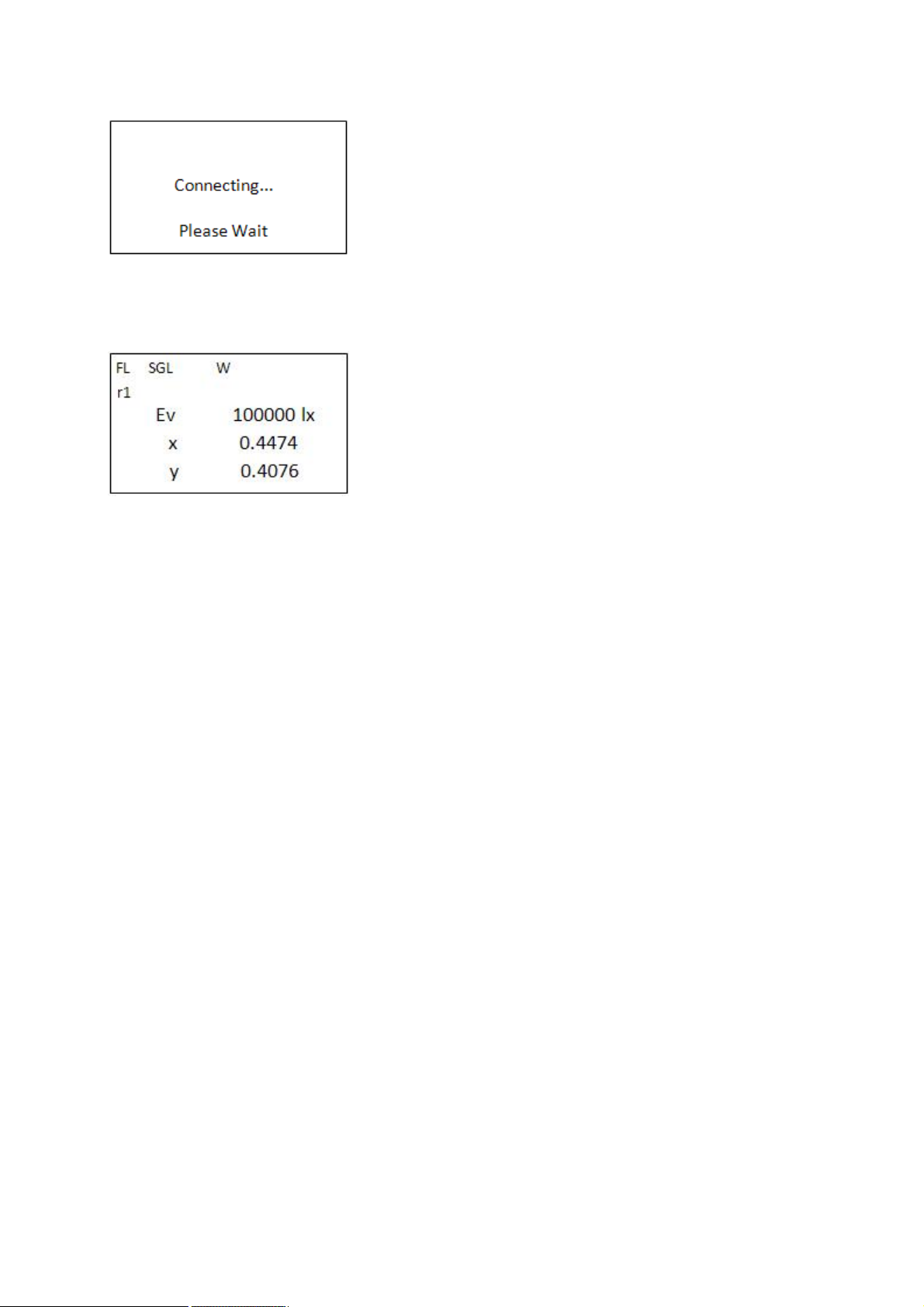
This chapter will explain how to connect the instrument with the wireless LAN access point (hereinafter,
access point).
• The explanation in this chapter will be done on the assumption that setting the access point has
already been finished.
• For setting and operating the access point, check the instruction manual of the access point.
• The procedure in this chapter is one example. It cannot be applied to some access points.
n Connection (when the access point has the easy connection AOSS function)
1. Set the IP address, subnet mask and port number of the instrument in the function mode. The IP
address must be fit to that on the access point.
2. Turn on the power of the access point and enable it to be connected.
3. Retrieve and set the access point in the function mode. After setting, cancel the function mode.
4. Press the [INV.] switch and then the [WPS] switch to connect with the access point.
53
Page 54

5. Press the [AOSS] button of the access point until the corresponding LED blinks twice.
6. When the connection is finished normally, “W” is indicated as the status display.
If the connection has failed several times, check the setting of the instrument and access point.
Then, wait for 3 minutes or more and start the connection again.
n Connection (when the access point does not have the easy connection function)
1. Set the IP address, subnet mask and port number of the instrument in the function mode. The IP
address must be fit to that on the access point.
2. Set “WEP” and “PASS PHRASE”, which are set for the access point, into the instrument.
3. Turn on the power of the access point and enable it to be connected.
4. Retrieve and set the access point in the function mode. After setting, cancel the function mode.
54
Page 55
5. Press the [INV.] switch and then [W-LAN] switch to connect with the access point.
6. When the connection is finished normally, “W” is indicated as the status display.
If the connection has failed several times, check the setting of the instrument and access point.
Then, wait for 3 minutes or more and start the connection again.
55
Page 56

Code
Contents
Remedial measure
Message
0
The instrument is
normal.
A remedial measure is not necessary.
1
13
A system error has
occurred.
Contact TOPCON TECHNOHOUSE.
When contacting our company, inform us
of the error code, the occurrence
frequency, the power supply status (AC
adapter or batteries) and the occurrence
status as detailedly as possible.
system error
mode change error
2 3 A trouble has occurred
in the internal memory.
It is probable that the internal memory is
damaged.
Restart the instrument by turning OFF and
then ON. Then, contact TOPCON
TECHNOHOUSE. When contacting our
company, inform us of the error code, the
occurrence frequency, the power supply
status (AC adapter or batteries), the
occurrence status and the condition at
restart as detailedly as possible.
memory init error
memory access error
5
The correction factor
calculation has failed.
Check the following points.
- Does an error occur when measurement
is performed?
- Is the measured value abnormal?
calculation error
6
The parameters are not
normal.
Check the following points.
- Are the parameters for sending within
the allowable setting range?
- Is the quantity of the parameters for
sending correct?
parameter error
7 9 Initialization of RS232C has failed.
Initialization of the
wireless LAN has
failed.
It is probable that the internal device is
damaged.
Restart the instrument by turning OFF and
then ON. Then, contact TOPCON
TECHNOHOUSE. When contacting our
company, inform us of the error code, the
occurrence frequency, the power supply
status (AC adapter or batteries), the
occurrence status and the condition at
restart as detailedly as possible.
RS-232C init error
LAN init error
5. ERROR CODE
5.1. ERROR CODE LIST
This chapter will explain the error messages and error codes that will be displayed on the instrument
and be obtained by the “ERR” command.
56
Page 57

Code
Contents
Remedial measure
Message
8
10
32
33
34
A trouble has occurred
in the RS-232C
communication.
A trouble has occurred
in the wireless LAN
communication.
Check the following points.
- Is the communication data (of wireless
LAN access point) set correctly in both
the external control device and the
instrument?
- Is the exclusive RS-232C cable
connected to both the external control
device and the instrument normally?
- Is the straight wiring cable used when
the RS-232C extension cable is used?
RS-232C trans error
LAN trans error
over run error
flamig error
parity error
11
12
Under range error has
occurred.
Over range error has
occurred.
Check the following points.
- Is the measured brightness within the
allowable measurement range?
- Is the measurement range mode set to
[AUTO FIRST] or [MANUAL RANGE]?
Is measurement performed where
brightness is sharply changed?
- Does the error occur though the
measurement range mode is set to
[AUTO FULL]?
under range error
over range error
14
The set value is beyond
the allowable range.
Set a value within the allowable range.
value out of range
17
18
19
20
21
22
A trouble has occurred
in motor or sensor.
It is probable that the motor or sensor is
damaged.
Restart the instrument by turning OFF and
then ON. Then, contact TOPCON
TECHNOHOUSE. When contacting our
company, inform us of the error code, the
occurrence frequency, the power supply
status (AC adapter or batteries), the
occurrence status and the condition at
restart as detailedly as possible.
mtor init error
mtor origin error
mtor move error
mtor sensor error
mtor signal error
mtor pos error
23
A trouble has occurred
in the photo detector or
internal PCB.
It is probable that the photo detector or
internal PCB is damaged.
Restart the instrument by turning OFF and
then ON. Then, contact TOPCON
TECHNOHOUSE. When contacting our
company, inform us of the occurrence
frequency, the power supply status (AC
adapter or batteries) and the occurrence
status as detailedly as possible.
count read error
31
The instrument has
exceeded the interval
time
Set the longer interval time than the
measurement time.
interval time over
57
Page 58

JIS class
Conforms to the general AA class illuminance meter
(JIS C 1609-1: 2006).
Spectral method
LVF (Linear Variable Filter)
Photo detector
Silicone photo diode array
Measurable wavelength range
380 nm - 780 nm
Output wavelength resolution
1 nm
Measurable illuminance range *1
2 - 1000000 lx
Accuracy *1
Illuminance Ev ±2% ±1digit
Chromaticity xy ±0.0050 (5 - 10 lx)
±0.0035 (10 - 50 lx)
±0.0020 (beyond 50 lx)
Repeatability *1, *2, *3
Illuminance Ev 0.5% +1digit
Chromaticity xy 0.0035 (5 - 10 lx)
0.0020 (beyond 10 lx)
Visible range relative spectral sensitivity
characteristics
(Difference from spectral relative luminous
efficiency: f1’)
2% or less
Systematic difference of angular incident
light characteristics: f2
3% or less
Ultra-violet range sensitivity characteristics
(ultra-violet range sensitivity: u)
2% or less
Infrared range sensitivity characteristics
(infrared range sensitivity: r)
2% or less
Fatigue characteristics: fF
Within ±1%
Temperature characteristics: fT
Within ±3% (-10 to 40°C with 23°C as reference)
Humidity characteristics: fH
Within ±3% (without dew condensation)
Characteristics against intermittent light: fC
Within ±2%
APPENDICES
SPECIFICATIONS & PERFORMANCE
* The display accuracy is the one set at shipment.
*1: Standard light A : In AUTO measurement range
*2: Illuminance Ev (2σ) : [2 standard deviation/average] in ten continuous measurements
*3: Chromaticity xy : [Maximum value - Minimum value] in ten continuous measurements
58
Page 59

Measurement range mode
AUTO
AUTO FULL / AUTO FIRST / AUTO ADJUST
MANUAL
MANUAL RANGE
Display mode
[Ev/x/y]
Illuminance Ev / Chromaticity x / Chromaticity y
[Ev/u’/v’]
Illuminance Ev / Chromaticity u’ / Chromaticity v’
[X/Y/Z]
Tristimulus values X/Y/Z
[Ev/Tcp/duv]
Illuminance Ev / Correlated color temperature Tcp /
Deviation duv
[Ev/Ra/Tcp]
Illuminance Ev /
Average color rendering property evaluation Ra /
Correlated color temperature Tcp
[Ev/λd/Pe]
Illuminance Ev / Dominant wavelength λd /
Excitation purity Pe
[Spectral radiation illuminace graph]
Warm-up time
When the measured illuminance is less than 20 lx: 10 minutes or more
*When the measured illuminance is 20 lx or more, warm-up is not
necessary.
Measurement time
Approx. 0.2 seconds
(When the measurement range is “MANUAL”, 100ms is fixed as the
integral time and the “STR2” command is used)
* The measurement time is sometimes longer due to the personal
computer specification, the use environment and the command
receiving timing.
Approx. 0.5 - 50 seconds (Measurement range: AUTO)
Display
Liquid crystal display unit with 128×64 dots and back light ON/OFF
function
Interface
RS-232C (The values are fixed except the baud rate.)
- Communication method
Full duplex
- Synchronization
Start-stop transmission
- Baud rate
9600/19200/38400 bps (Bits Per second)
- Data length
7 bits
- Parity
Odd number (ODD)
- Stop bit
1 bit
- Communication type
Text (ASCII)
- Delimiter
CR + LF
Wireless LAN (exclusively for Japan)
- Standard to be observed
IEEE802.11b infrastructure/ad hoc mode
- Frequency range
2.4GHz band (1-13ch)
- Communication distance
Indoors 10m/Outdoors 15m typ
- Baud rate
38400 bps
- Security
WEP/WPA/WPA2
59
Page 60
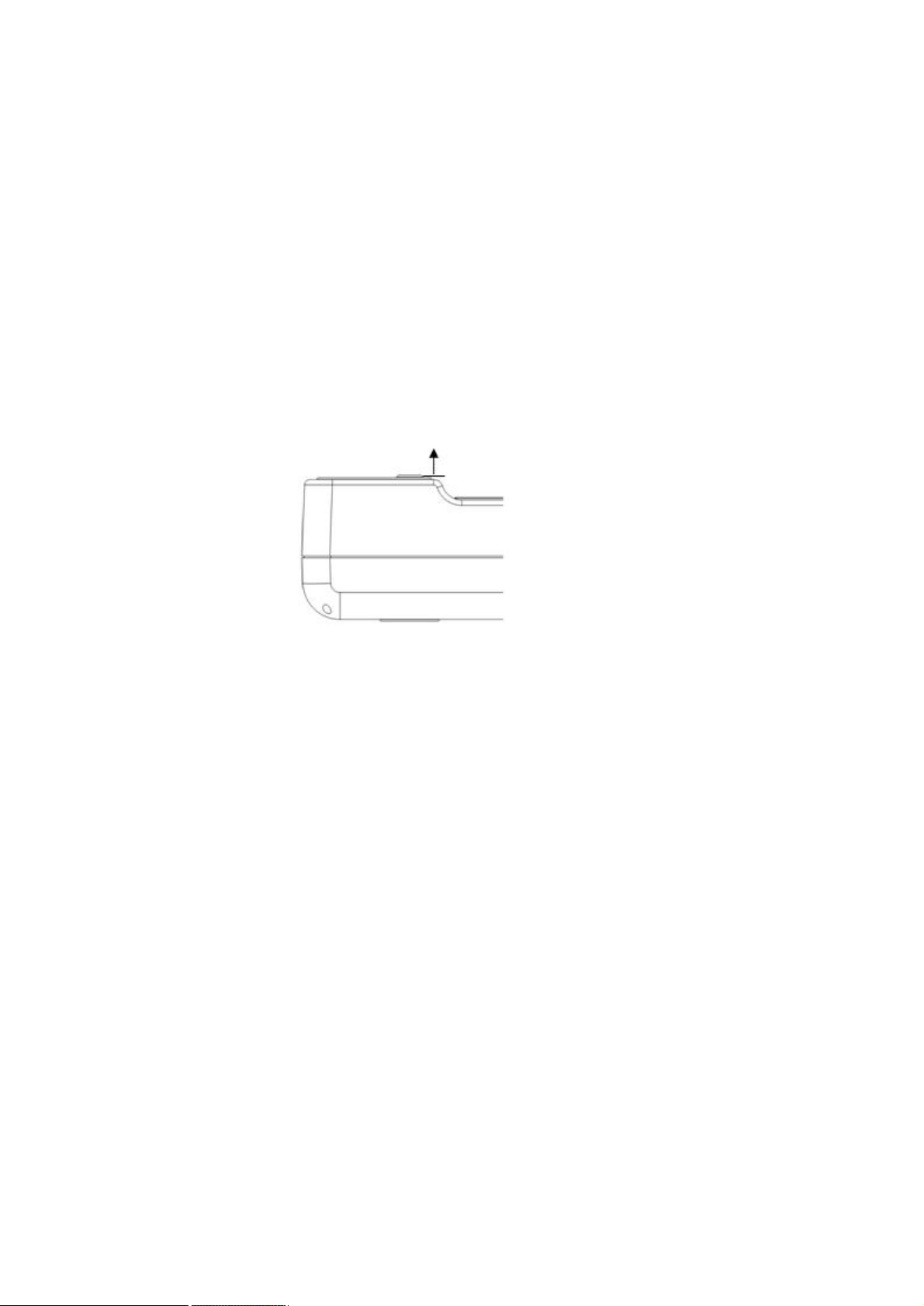
Power supply
Nickel hydride AA battery: 4 pcs. (Standard accessory)
*Battery life (Operable time): Approx. 7 hours
(When the new nickel hydride batteries (standard accessory) are fully
charged)
Exclusive AC adapter (optional accessory)
Operating conditions
Temperature -10°C - +40°C
Humidity 85%RH or less (without dew condensation)
Storing conditions
Temperature -10°C - +50°C
Humidity 85%RH or less (without dew condensation)
External dimensions
Approx. 70 (width) × 250 (depth) × 78 (height) mm
(Without beam detector cap and power switch)
Weight
Approx. 640g (including the batteries)
Measurement reference surface
Edge of beam detector
60
Page 61

BLOCK DIAGRAM
Filter turret
Diffusion
plate
Operational
Amplifier
Power supply system and
control system
AC adapter
Battery
Silicone photo
diode array
Motor
Sensor
PCB
Power switch
(Option)
Keyboard
A/D
converter
Liquid crystal
display unit
Analog
PCB
DC-DC
converter
Motor driver
Wireless
LAN module
Visible range spectral relative luminous efficiency IM-1000
Wavelength (nm)
GRAPH
Visible range relative spectral sensitivity characteristics (Typical value)
61
Page 62

EXTERNAL DIMENSIONS DIAGRAM
Power switch
Battery box
Air vent
Light receiving unit ø14
Keyboard
Strap attaching unit
(Tool screw)
1/4-20UNC Depth 5
(Tripod screw for JIS
B7103 camera)
RS-232C
62
Page 63

FCC Compliance Information
This equipment has been tested and found to comply with the limits for a Class A digital device, pursuant
to part 15 of the FCC Rules.
These limits are designed to provide reasonable protection against harmful interference when the
equipment is operated in a commercial environment. This equipment generates, uses, and can radiate
radio frequency energy and, if not installed and used in accordance with the instruction manual, may cause
harmful interference to radio communications. Operation of this equipment in a residentia l area is likely to
cause harmful interference in which case the user will be required to correct the interference at his own
expense.
This device complies with Part 15 of FCC Rules. Operation is subject to the following two conditions:
(1) the device may not cause interference, and (2) the device must accept any interference, including
interference that may cause undesired operation of this device.
IMPORTANT NOTE:
FCC RF Radiation Exposure Statement:
This equipment complies with FCC RF radiation exposure limits set forth for an uncontrolled environment.
This equipment should be installed and operated with a minimum distanc e of 20 centimeters between the
radiator and your body. This transmitter must not be co-located or operating in conjunction with any other
antenna or transmitter.
NOTE: THE GRANTEE IS NOT RESPONSIBLE FOR ANY CHANGES OR MODIFICA
TIONS NOT EXPRESSLY APPROVED BY THE PARTY RESPONSIBLE FOR COMPLIA
NCE. SUCH MODIFICATIONS COULD VOID THE USER’S AUTHORITY TO
OPERATE THE EQUIPMENT.
Page 64

Warranty Period
One year from the date of shipment from TOPCON TECHNOHOUSE.
Repair During Warranty Period
If trouble should arise during normal use of the IM-1000, we will make repairs resulting from design or
manufacturing defects at no charge.
Repair After Warranty Period
If functionality can be restored through repair, we will repair your instrument for a charge.
Maintenance Period
We will stock functional repair parts
We will repair the IM-1000 while these parts remain in stock.
After the stocking period, we may be able to repair the IM-1000. Consult with your retailer or TOPCON
TECHNOHOUSE for futher details.
(*1) Functional repair parts are those parts required to make the IM-1000 function.
(*2) Although we strive to meet this stocking period, it may be shortened due to unforeseen
circumstances.
(*1)
for eight years
(*2)
from the date of manufacture.
Disposal
Follow local disposal and recycling ordinances when disposing of the IM-1000.
Please have the following information available when making an inquiry:
· Serial number: Noted on the specification plate on the bottom of the instrument.
· Use period: The dates of purchase as well as the last calibration.
∙ Environment: Type of measurement light source, instrument settings,
measurement values, measurement status, etc.
∙ Description of problem: As detailed as possible.
Inquiries: Refer to the back cover of this manual for contact information.
Page 65

Contact information:
LUMINANCE METER
75-1 Hasunuma-cho, Itabashi-ku, Tokyo 174-8580 Japan
◆ Inquiries regarding the product
Sales Department Tel 03(3558) 2666 Fax 03 (3558) 4661
◆ Inquiries regarding repairs and maintenance
Service Department Tel 03 (3558) 2710 Fax 03 (3558) 3011
Luminance Meter IM-1000
Instruction Manual
2012 Edition
Date of issue First edition : July, 2012
1.1 edition : August, 2012
Published by: Topcon Technohouse Corporation
©2012 TOPCON TECHNOHOUSE CORPORATION
ALL RIGHTS RESERVED
Unauthorized copying prohibited.
 Loading...