

Page 1

HiPer VR
GNSS Receiver
Quick Reference Card
Page 2
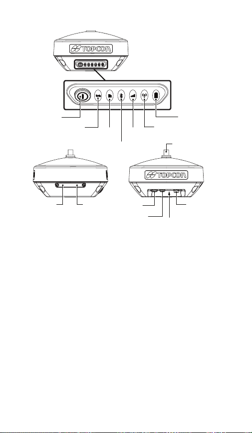
Features
USB
Power
Button
Reset
Button
STAT
REC Cellular
SIM Card
(Model
dependent)
Bluetooth
Power
Serial
Radio
Micro
Battery
TNC or
BNC
External
GNSS
Antenna
Getting Started
Turning the Receiver On and Off
To turn on the receiver, press and hold the power button until the LEDs briey
ash. The receiver is turning on when: the Power LED blinks green, the receiver
channels initialize and start tracking all visible satellites at any time and location,
and the serial port is available. When the startup is complete, the Power LED is
solid green only when external power is used; otherwise the Power LED is off.
After startup, the integrated wireless devices in the receiver are ready to use,
and the receiver is available to obtain the correction data from reference station
and to measure ground point coordinates with high accuracy. Also the receiver
is ready to start data recording to the internal memory.
To turn-off the receiver, press and hold the power button for more than 3 but
less than 10 seconds. Release the power button when the Power LED blinks
yellow. This delay prevents the receiver from being turned off by mistake.
Allow the receiver to complete the power off cycle, which is approximately 15
seconds.
Powering the Receiver
The receiver is powered by an internal battery or an external valid power source
connected to the power port. If an external power source is connected, the
receiver draws power from it instead of the battery. You can connect the receiver
to an external power source, such as a vehicle battery, with 9 – 27 VDC to
operate the receiver.
Page 3
A power input greater than 27 VDC could damage the
receiver.
Charging the internal battery
1. Connect the supplied power cable to the receiver’s power port.
2. Connect the SAE connector of the power cable to the SAE connector of the
power adapter.
3. Plug the power adapter into an available outlet for approximately ve hours to
fully charge the battery.
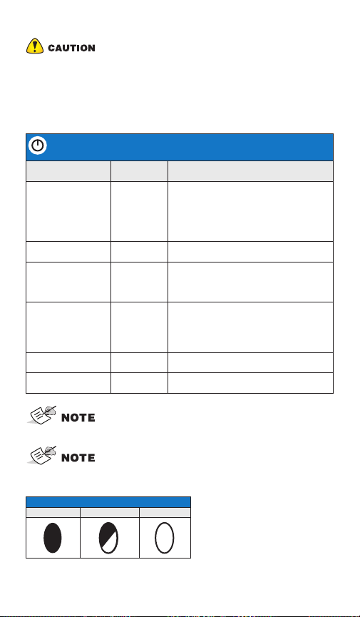
POWER BUTTON FUNCTIONS
FUNCTION
Power On 1+ seconds
Power O 3-10 seconds
Start/Stop Data
Logging
Toggling between
Static and Kinematic
post-processing
modes
Performing factory
reset
Emergency Power
O
PRESS
BUTTON
Press three
times in a
row within 2
seconds
Press three
times in a
row within 1
second
10-15
seconds
60 seconds
A delay of several seconds occurs between the last clicking
of the Power button and rst blinking/last blinking of the
REC LED.
When using external power, the Power LED is solid green
except for startup and shutdown procedures.
LED DESCRIPTION
Power LED blinks until startup completes.
After that the LED light is solid green, if
the external power source is connected to
the receiver. If the external power source
is not connected to the receiver, the LED
is o.
Release the Power button when the STAT
LED turns yellow.
Refer to the REC (Recording) LED
description.
Refer to the REC (Recording) LED
description.
This function is available for “Occupation
mode switch” only. See Topcon Receiver
Utility (TRU) Help.
Release Power button when STAT LED
blinks magenta.
Release the Power button when all of the
LEDs are o.
LED Display Panel
LED ICON KEY
SOLID BLINKING OFF
Page 4

STATUS LED
Green Blink One blink per tracked GPS satellite.
Yellow Blink One blink per tracked GLONASS satellite.
Cyan Blink One blink per tracked Galileo satellite.
Magenta Blink One blink per tracked BeiDou satellite.
Blue Blink One blink per tracked QZSS satellite.
White Blink One blink per tracked L-band Satellite.
Red Blink
Red Solid
+ Green Solid
+ Yellow Solid
RECORDING (REC) LED
LED blink mode switch enabled
Green Blink File logging is in progress.
Red Solid
Occupation mode switch enabled
Green Blink
Yellow Blink
Red Solid
BLUETOOTH LED
Blue Blink Bluetooth is on and waiting for a connection.
One blink when there are no tracked satellites or
solutions. Two blinks per second when the receiver is in
exception mode. Otherwise, the LED is o.
OAF is expired.
File logging is in progress. The Static mode is the current
post-processing mode.
File logging is in progress. Static mode is the current postprocessing mode.
File logging is in progress. Kinematic mode is the current
post-processing mode.
File logging problem. No free memory, or hardware
problem with data recording.
LED is o when le is not logging data.
Blue Solid A single Bluetooth connection has been established.
Blue Solid +
Blue Blink *N
every 10
seconds
Multiple (N) valid Bluetooth connections have been
established.
Page 5

RADIO LED - UHF GNSS RECEIVER
Command mode (rover and base)
Red Blink
+ Green Blink
+ No light
Receiver mode (rover)
Green Solid Modem is not receiving correction data.
Yellow Blink Modem is receiving correction data from a base.
Transmitter mode (base)
Green Solid Modem is not transmitting correction data.
Red Blink Modem is transmitting correction data.
Retranslator mode (base)
Yellow Blink
+ Red Blink
RADIO LED - FH915+ GNSS RECEIVER
Command Mode (rover and base)
Red Blink
+ Green Blink
Receiver mode (rover)
Green Blink Modem is not synchronized with a base.
Green Solid
Yellow Solid Modem receives correction data from a base.
Transmitter mode (base)
Red Solid Modem transmits correction data.
MAGNET Field or TRU sends commands to congure the
GNSS receiver.
Modem is receiving and transmitting correction data.
MAGNET Field or TRU sends commands to congure
the modem.
Modem is synchronized with a base and ready to receive
correction data.
BATTERY LED
The receiver is on—and the internal battery is in use
Green Solid The charge is greater than 50%.
Yellow Solid The charge is between 10% and 50%.
Red Solid The charge is less than 10%.
Page 6

BATTERY LED
The receiver is on—and the external power source is in use
Green Solid The internal battery is fully charged.
Green Blink
Yellow Blink
Red Blink
The internal battery is at greater than 50% capacity; the
battery is charging.
The internal battery is at greater than 10% capacity; the
battery is charging.
The internal battery is at less than 10% capacity; the
battery is charging.
The receiver is off
Green Solid
Green Blink
Yellow Blink
No Light
The receiver is connected to an external power source,
and the battery is fully charged.
The receiver is connected to an external power source,
and the battery is at greater than 50% capacity; the
battery is charging.
The receiver is connected to an external power source,
and the battery is at less than 50% capacity; the battery
is charging.
The receiver is not connected to an external power
source.
Regulatory and Safety Warnings
Product Conformity
Hereby, Topcon declares that the HiPer VR radio modem is in compliance with the essential
requirements (radio performance, electromagnetic compatibility, and electrical safety)
and other relevant provisions described in Directive 2014/53/EU. The full text of the EU
declaration is available at the following internet address:
https://www.topconpositioning.com/support/products/hiper-vr
Therefore, the equipment is labeled with the CE-marking. The operating frequency range of
the device is not harmonized throughout the market area and the local spectrum authority
should be contacted prior to use.
Class A Digital Device Statement
This equipment has been tested and found to comply with the limits for a Class A digital
device pursuant to part 15 of the FCC rules. These limits are designed to provide reasonable
protection against harmful interference when the equipment is operated in a commercial
environment. This equipment generates, uses, and can radiate radio frequency energy and,
if not installed and used in accordance with the instruction manual, may cause harmful
interference to radio communications. Operation of this equipment in a residential area is
likely to cause harmful interference in which case the user will be required to correct the
interference at his own expense.
If this equipment does cause interference to radio or television equipment reception, which
can be determined by turning the equipment off and on, the user is encouraged to try to
correct the interference by one or more of the following measures:
• Reorient or relocate the receiving antenna.
• Move the equipment away from the receiver.
• Plug the equipment into an outlet on a circuit different from that to which the receiver is
powered.
• Consult the dealer or an experienced radio/television technician for additional suggestions.
Page 7

Restrictions on Use
For more information contact Synergy Positioning Systems or
visit the Synergy Positioning Systems website at www.synergypositioning.co.nz
All branches: Phone 0800 867 266 Email: info@synergypositioning.co.nz
The HiPer VR UHF radio modem has been designed to operate only at specic frequencies.
The exact frequency in use differs from one region and/or country to another. The user of a
radio modem must take care that the said device is not operated without the permission of
the local authorities on frequencies other than those specically reserved and intended for
use without a specic permit.
The HiPer VR UHF (406-470 MHz) is allowed to be used in the following countries, either
on license free channels or on channels where the operation requires a license. Additional
detailed information is available at the local frequency management authority.
Countries*: AT, BE, BG, CY, DK, FI, FR, DE, GR, IS, IE, IT, LU, MT, NL, NO, ES, SE, CH, GB,
AU, CA, CZ, EE, HU, LV, LT, PL, PT, RO, SI, SK, ZA and US.
* codes of the countries follow the ISO 3166-1-Alpha-2 standard
RF Exposure Warning
To comply with RF exposure requirements, maintain at least 37 cm
between the user and the GNSS receiver.
Battery Warning
Do not attempt to open the battery pack or replace it.
Do not disassemble the battery pack.
Do not charge in conditions different than specied.
Do not use other than the specied battery charger.
Do not short circuit.
Do not crush or modify.
Dispose of batteries according to your local regulations.
Technical Documentation and Utility Software
On the Topcon Support website (www.topconpositioning.com/support), you
can download manuals, technical documentation, training material, and
various utility software to help you set up and use your Topcon product.
The website also offers registration resources, training, and technical
assistance.
Register for a free account at https://www.topconpositioning.com/support
today to download this material.
Your local authorized dealer is:
Page 8

www.topconpositioning.com
HiPer VR Quick Reference Card
©2018 Topcon Corporation 7400 National Drive, Livermore CA 94550 All rights reserved.
Specifications subject to change without notice.
P/N 1027033-01 Rev. A
 Loading...