

Page 1
INSTRUCTION MANUAL
AUTO TRACKING TOTAL STATION
GTS-820A
SERIES
GTS-821A
GTS-822A
GTS-823A
GTS-825A
Page 2

Page 3

FOREWORD
Thank you for purchasing the TOPCON Auto Tracking Total Station, GTS-82 0A
series. For the best performance of the instruments, please carefully read these
instructions and keep them in a convenient location for future reference.
General Hand l ing Prec autions
Before starting work or operation, be sure to check that the instrument is functioning
correctly with normal performance.
Do not submerge the instrument into water.
The instrument can not be submerged underwater.
The instrument is designed based on the International Standard IP54, therefore it is protected from
the normal rainfall.
Setting the instrument on a tripod
When mounting the instrument on a tripod, use a wooden tripod when possible. The vibrations that
may occur when using a metallic trip od can effect the measuring precision.
Installing the tribrach
If the tribra ch is ins talle d inco rrec tly, the measuring pr ecis ion coul d be effec ted . Occasional ly check the
adjusting screws on the tr i brach. Make s ur e the base fix ing lever is locked and the base fixing screws
are tightened.
TR-5 or TR-5P tribrach should be used for prism side when the traverse s urveys is perfor med .
FORE W ORD
Guarding the instrument against shocks
When tr anspo r ting t he instrum ent, p ro vide some pr otection t o m in imize risk of shocks. Heavy shocks
may cause the measurement to be faulty.
Carrying the instrument
Always carry the instrument by its handgrip.
Exposing the instrument to extreme heat.
Do not leave the instrument in extreme heat for longer than necessary. It could adversely affect its
performance.
Sudden changes of temperature
Any sudden change of temperature to the instrument or prism may result in a reduction of measuring
distance range, i.e when taking the instrument out from a heated vehicle. Let instrument acclimate
itself to ambient temperature.
Battery level check
Confirm battery level remaining before operating.
Memory back up
The instrument has a built in battery for memory back up. If the battery power is low, “Back up battery
empty” will display. It is still possible to measure the distance and the angle , but t h e measured data
and the parameter setting can be lost . Cont act your dealer, to replace the battery.
Taking the battery out
It is recommended not to take the battery out during the power is on. All the data stored is possible
gone at th at t i me. So please do your assembling or ta ki ng the bat ter y out after the pow er i s off .
No responsibility
TOPCON Corporation has no responsibility for loss of data stored in the memory in case unexpected
accidents.
1
Page 4

FORE W ORD
Rotating the instrument and telescope
Rota t i on of t he inst rum ent or tel escope is driven electronically in normal operation.
Do not disturb the rotation.
Storage in the case
Keep the telescope horizontally and turn the instrument to align its mark with the lower base mark
(Storage mark). Keep its objective lens si de downward . Sto r ing it in the case in any other way may
cause damage. Hold the hand grips and base with both hands, when taking the instrument out of the
case, or putting the equ i pm ent i n th e case.
Maintenance for driving parts.
Every 4,000~5, 000 hours operation in total, cha nge grease of driving parts.
Contact your dealer or TOPCON Head Office for the maintenance.
2
Page 5
FORE W ORD
G
Display for Safe Use
In order to encourage the safe use of products and prevent any danger to the operator and others or
damage to properties, important warnings are put on the products and inserted in the instruction
manuals.
We suggest that everyone understand the meaning of the following displays and icons before reading
the “Safety Cautions” and text
Display Meaning
WARNIN
CAUTION
•Injury refers to hurt, burn, electric shock, etc.
•Physical damage refers to extensive damage to buildings or equipment and furniture.
Ignoring or disregard of this display may lead to t he danger of death or
serious injury.
Ignoring or disregard of this display may lead to personal injury or physical damage.
Safety Caut ions
WARNING
•There is a risk of fire, electric shock or physical harm if you attempt to disassemble or
repair the instrument yourself.
This is only to be carried out by TOPCON or an authorized dealer, only!
•Cause eye injury or blindness.
Do not look at the sun through a telescope.
•Laser beams can be dangerous, and can cause eye injury's if used incorrectly.
Never attempt to repair the instrument yourself.
•Cause eye injury or blindness.
Do not stare into beam.
•High temperature may cause fire.
Do not cover the charger while it is charging.
•High temperature may cause fire.
Do not connect the battery to an instrument while it is charging.
•Risk of fire or electric shock.
Do not use damaged power cable, plug and socket.
•Risk of fire or electric shock.
Do not use a wet battery or charger.
•May ignite explosively.
Never use an instrument near flammable gas, liquid matter, and do not use in a coal mine.
•Battery can cause explosion or injury.
Do not dispose in fire or heat.
•Risk of fire or electric shock.
Do not use any power voltage except the one given on manufacturers instructions.
•Battery can cause outbreak of fire.
Do not use any other type of charger other than the one specified.
•Risk of fire.
Do not use any other power cable other than the one specified.
•Battery can cause outbreak of fire.
Do not block up the vent of the battery.
•The short circuit of a battery can cause a fire.
Do not short circuit battery when storing it.
3
Page 6

FORE W ORD
CAUTION
Use of controls or adjustment or performance of procedures other than those specified herein
may result in hazardous radiation exposure.
Let the laser beam reach the aimed object or the target without anybody else in the laser beam
path. In case you operate laser beam open, avoid radiating laser beam to the height of man's
head. It is quite possible for the beam to enter into one's eyes, and it is possible to lose visual
sight temporarily, and lose one's caution and awareness of other dangers - avoid glaring beam.
Do not connect or disconnect equipment with wet hands, you are at risk of electric shocks if you
do!
Risk of injury by overturn the carrying case.
Do not stand or sit on th e carrying cases.
Please note that the tips of tripod can be hazardous, be aware of this when setting up or carrying
the tripod.
Risk of injury by falling down the instrument or case.
Do not use a carrying case with a damaged which belts, grips or latches.
Do not allow skin or clothing to come into contact with acid from the batteries, if this does occur
then wash off with copious amounts of water and seek medical advice.
A plumb bob can cause an injury to a person if used incorrectly.
It could be dangerous if the instrument falls over, please ensure you attach a handle battery to
the instrument securely.
Ensure that you mount the Tribrach correctly, failing to do so may result in injury if the tribrach
were to fall over.
It could be dangerous if the instrument falls over, please check that you fix the instrument to the
tripod correctly.
Risk of injury by falling down a tripod and an instrument.
Always check that the screws of tripod are tightened.
User
1)This product is for professional use only!
The user is required to be a qualified surveyor or have a good knowledge of surveying, in order to
understand the user and safety instructions, before operating, inspecting or adjusting.
2)Wear the required protectors (safety shoes, helmet, e tc.) when operating.
Exceptions fr om Respo ns ibility
1)The user of this product is expected to follow all operating instructions and make periodic checks of the
product’s performance.
2)The manufacturer, or its representatives, assumes no responsibility for results of a faulty or intentional
usage or misuse including any direct, indirect, consequential damage, and loss of profits.
3)The manufacturer, or its representative s, assumes no responsibility for co ns equential damage, and
loss of profits by any disaster, (an earthquake, storms, floods etc.).
A fire, accident, or an act of a third party and/or a usage any other usual conditions.
4)The manufactur er , or its represent ativ es, assumes no respon si bility for any damage, and loss of pr ofits
due to a change of data, loss of data, an in terruption of business etc., caused by using the product or
an unusable product.
5)The manufactur er , or its represent ativ es, assumes no respon si bility for any damage, and loss of pr ofits
caused by usage except for explained in the user manual.
6)The manufacturer, or its representative s, assumes no responsibility for damage c aused b y wrong
movemen t , or ac t i o n due to connecti n g with o th er products.
4
Page 7
Laser Safety
GTS-820A series uses the visible laser beam for auto tracking, optical communication. The
GTS-820A series products are manufactured and sold in accordance with “Radiation Safety of Laser
Products, Equip men t Classificati on, Require me nts and Use r‘s Guid e” (I EC Pub li cation 60825-1 ) or
“Performance Standards for Light-Emitting Products” (FDA/BRH 21 CFR 1040) provided on the safety
standards for laser beam.
As per the said standards, GTS-820A series is classified as “Class 2 (CLASS II) Laser Products”.
The laser beam belongs not very dangerous type but we request you to keep and understand “Safety
standard for users” as mentione d in the manual inst ruction.
In case of any failure, do not disassemble the instrument. Contact TOPCON or your TOPCON dealer.
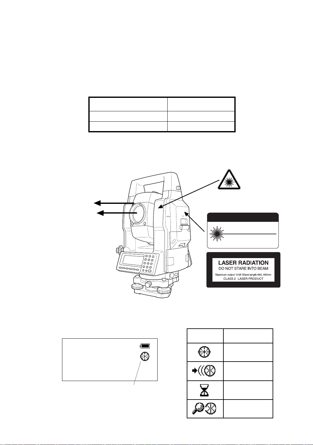
Laser class of each mode is as foll o ws.
Mode Laser class
Autotracking Class 1 (CLASS II)
Optical communication Class 2 (CLASS II)
Labels
Find the labels which describes the caution and safety about the laser beam as follows in GTS-820A
series.
We request you to replace it one anytime the caution labels are damaged or lost and paste a new one
at the same place. You can get the labels from Topcon or your dealer.
Warning Label
Beam ap ertur e
Explanatory Label
Beam ap ertur e
CAUTION
LASER RADIATION-DO NOT
STARE INTO BEAM
WAVE LENGTH 660, 690nm
1mW MAXIMUM OUTPUT
DIODE LASER
CLASS II LASER PRODUCT
FORE W ORD
Each label is differed by the market.
GTS-820A series
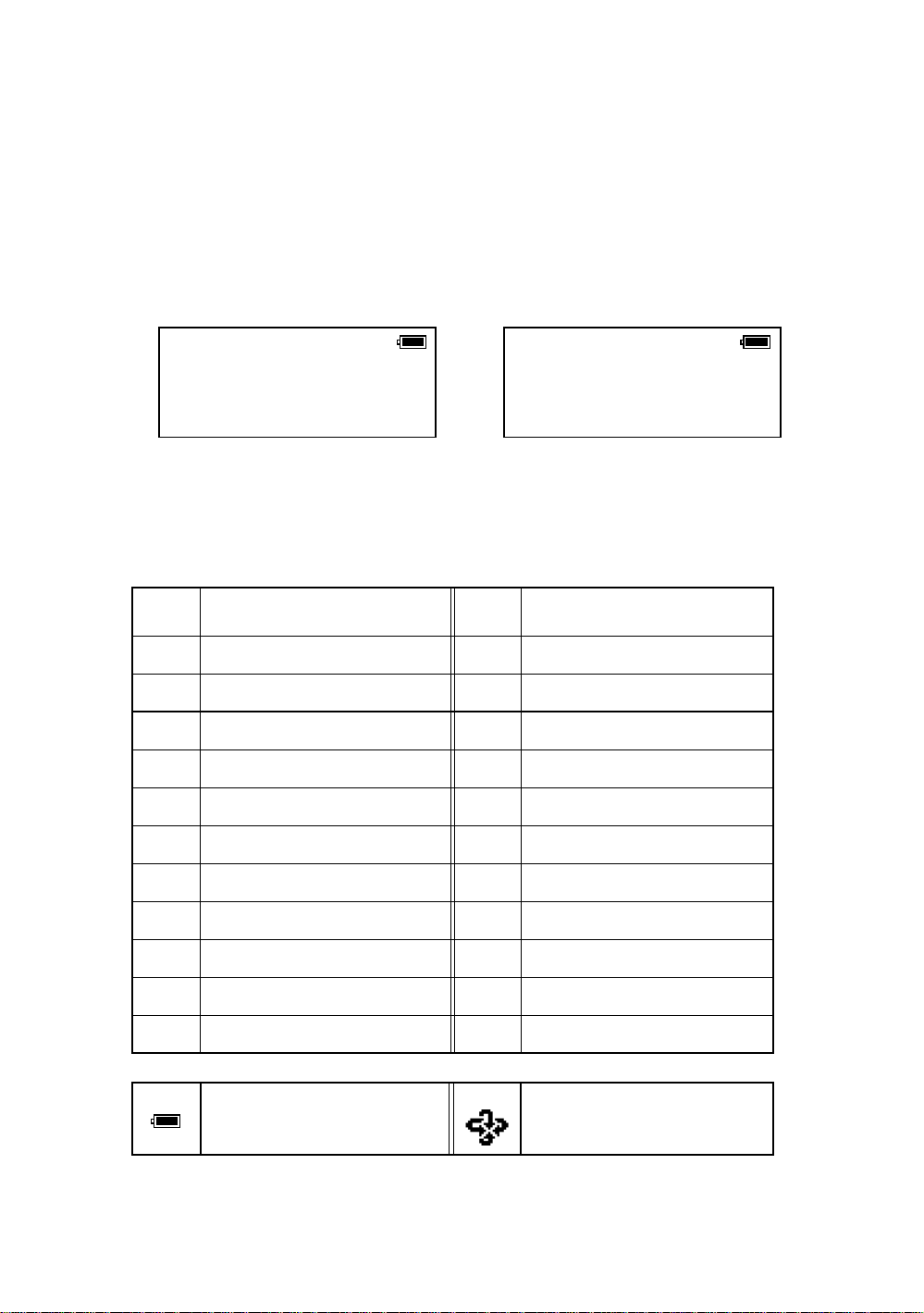
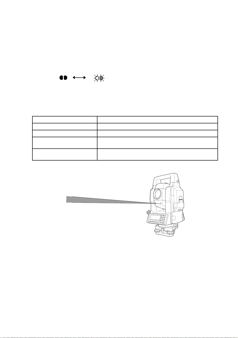
Symbol marks while the laser is emitting.
The following symbol marks of instrument status will indicate that the laser is emitting.
Marks
V : 87°55'45"
HR: 180°44'12"
SD HD NEZ 0SET HOLD P1↓
The symbol mark
Status of
instrument
Auto-collimating
Auto-tracking
Waiting
Searching
5
Page 8

Contents
FOREWORD . . . . . . . . . . . . . . . . . . . . . . . . . . . . . . . . . . . . . . . . . . . . . . . . . . 1
General Handling Precautions. . . . . . . . . . . . . . . . . . . . . . . . . . . . . . . . . . . . . . . . . . . . . . . . 1
Display for Safe Use . . . . . . . . . . . . . . . . . . . . . . . . . . . . . . . . . . . . . . . . . . . . . . . . . . . . . . . 3
Safety Cautions . . . . . . . . . . . . . . . . . . . . . . . . . . . . . . . . . . . . . . . . . . . . . . . . . . . . . . . . . . . 3
User . . . . . . . . . . . . . . . . . . . . . . . . . . . . . . . . . . . . . . . . . . . . . . . . . . . . . . . . . . . . . . . . . . . . 4
Exceptions from Responsibility . . . . . . . . . . . . . . . . . . . . . . . . . . . . . . . . . . . . . . . . . . . . . . . 4
Laser Safety. . . . . . . . . . . . . . . . . . . . . . . . . . . . . . . . . . . . . . . . . . . . . . . . . . . . . . . . . . . . . . 5
Contents. . . . . . . . . . . . . . . . . . . . . . . . . . . . . . . . . . . . . . . . . . . . . . . . . . . . . . . . . . . . . . . . . 6
Standard Set Composition. . . . . . . . . . . . . . . . . . . . . . . . . . . . . . . . . . . . . . . . . . . . . . . . . . . 9
1 NOMENCLATURE AND FUNCTIONS . . . . . . . . . . . . . . . . . . . . . . . . . . 1-1
1.1 Nomenclature . . . . . . . . . . . . . . . . . . . . . . . . . . . . . . . . . . . . . . . . . . . . . . . . . . . . . . . .1-1
1.2 Display . . . . . . . . . . . . . . . . . . . . . . . . . . . . . . . . . . . . . . . . . . . . . . . . . . . . . . . . . . . . . 1-3
1.3 Operating Key. . . . . . . . . . . . . . . . . . . . . . . . . . . . . . . . . . . . . . . . . . . . . . . . . . . . . . . .1-4
1.4 Function Key (Soft Key) . . . . . . . . . . . . . . . . . . . . . . . . . . . . . . . . . . . . . . . . . . . . . . . . 1-5
1.5 Star key (*key) mode . . . . . . . . . . . . . . . . . . . . . . . . . . . . . . . . . . . . . . . . . . . . . . . . . . 1-7
1.6 Auto Power Off . . . . . . . . . . . . . . . . . . . . . . . . . . . . . . . . . . . . . . . . . . . . . . . . . . . . . . 1-11
1.7 Data Output. . . . . . . . . . . . . . . . . . . . . . . . . . . . . . . . . . . . . . . . . . . . . . . . . . . . . . . . .1-11
1.8 Rotating Method . . . . . . . . . . . . . . . . . . . . . . . . . . . . . . . . . . . . . . . . . . . . . . . . . . . . . 1-11
1.8.1 Rotating by H/V Shuttle and H/V Jog. . . . . . . . . . . . . . . . . . . . . . . . . . . . . . . . . 1-11
1.8.2 Auto Inversion . . . . . . . . . . . . . . . . . . . . . . . . . . . . . . . . . . . . . . . . . . . . . . . . . . 1-11
1.8.3 Rotating automatically to a required Horizontal and Vertical angle . . . . . . . . . . 1-11
1.9 Using together with RC-2II Remote Control System. . . . . . . . . . . . . . . . . . . . . . . . . . 1-12
1.10 Using connecting with Personal Computer (PC). . . . . . . . . . . . . . . . . . . . . . . . . . . . 1-13
2 PREPARATION FOR MEASUREMENT . . . . . . . . . . . . . . . . . . . . . . . . . 2-1
2.1 Power Connection. . . . . . . . . . . . . . . . . . . . . . . . . . . . . . . . . . . . . . . . . . . . . . . . . . . . . 2-1
2.2 Setting Instrument Up For Measurement . . . . . . . . . . . . . . . . . . . . . . . . . . . . . . . . . . . 2-2
2.3 Power Switch Key ON. . . . . . . . . . . . . . . . . . . . . . . . . . . . . . . . . . . . . . . . . . . . . . . . . . 2-3
2.4 Battery Level Indicator . . . . . . . . . . . . . . . . . . . . . . . . . . . . . . . . . . . . . . . . . . . . . . . . . 2-4
2.5 Main Menu Icons. . . . . . . . . . . . . . . . . . . . . . . . . . . . . . . . . . . . . . . . . . . . . . . . . . . . . . 2-5
2.6 Vertical and Horizontal Angle Tilt Correction . . . . . . . . . . . . . . . . . . . . . . . . . . . . . . . . 2-6
2.7 Compensation of Systematic Error of Instrument . . . . . . . . . . . . . . . . . . . . . . . . . . . . . 2-7
2.8 Resume Mode ON/OFF . . . . . . . . . . . . . . . . . . . . . . . . . . . . . . . . . . . . . . . . . . . . . . . . 2-8
2.9 How to Enter Numerals and Alphabet Letters. . . . . . . . . . . . . . . . . . . . . . . . . . . . . . . . 2-8
2.10 Memory Card . . . . . . . . . . . . . . . . . . . . . . . . . . . . . . . . . . . . . . . . . . . . . . . . . . . . . . . 2-9
2.11 Inclination of Prism and Measuring Error . . . . . . . . . . . . . . . . . . . . . . . . . . . . . . . . . 2-10
3 AUTOMATIC TRACKING / AUTOMATIC COLLIMATION . . . . . . . . . . 3-1
3.1 Automatic Tracking . . . . . . . . . . . . . . . . . . . . . . . . . . . . . . . . . . . . . . . . . . . . . . . . . . . . 3-1
3.2 Automatic Collimation . . . . . . . . . . . . . . . . . . . . . . . . . . . . . . . . . . . . . . . . . . . . . . . . . . 3-3
3.3 Range of Laser for Auto-tracking and Auto-collimating . . . . . . . . . . . . . . . . . . . . . . . . 3-4
3.4 Setting Parameters for Auto-Tracking. . . . . . . . . . . . . . . . . . . . . . . . . . . . . . . . . . . . . . 3-5
3.4.1 Setting Items . . . . . . . . . . . . . . . . . . . . . . . . . . . . . . . . . . . . . . . . . . . . . . . . . . . . 3-5
3.4.2 How to set the parameters. . . . . . . . . . . . . . . . . . . . . . . . . . . . . . . . . . . . . . . . . . 3-7
4 STANDARD MEASUREMENT MODE . . . . . . . . . . . . . . . . . . . . . . . . . . 4-1
4.1 Angle Measurement . . . . . . . . . . . . . . . . . . . . . . . . . . . . . . . . . . . . . . . . . . . . . . . . . . . 4-1
4.1.1 Measuring Horizontal Angle Right and Vertical Angle . . . . . . . . . . . . . . . . . . . . . 4-1
4.1.2 Switching Horizontal Angle Right/Left . . . . . . . . . . . . . . . . . . . . . . . . . . . . . . . . . 4-2
4.1.3 Measuring from the Required Horizontal Angle. . . . . . . . . . . . . . . . . . . . . . . . . . 4-2
4.1.4 Vertical Angle Percent Grade(%) Mode. . . . . . . . . . . . . . . . . . . . . . . . . . . . . . . . 4-3
4.1.5 Automatic Rotation to a Required Horizontal and Vertical Absolute Angle . . . . .4-4
4.2 Distance Measurement. . . . . . . . . . . . . . . . . . . . . . . . . . . . . . . . . . . . . . . . . . . . . . . . . 4-5
4.2.1 Setting of the Atmospheric Correction . . . . . . . . . . . . . . . . . . . . . . . . . . . . . . . . . 4-5
4.2.2 Setting of the Correction for Prism Constant . . . . . . . . . . . . . . . . . . . . . . . . . . . . 4-5
4.2.3 Distance Measurement (Continuous Measurement) . . . . . . . . . . . . . . . . . . . . . . 4-5
4.2.4 Distance Measurement (Single/N-times Measurement) . . . . . . . . . . . . . . . . . . . . 4-6
4.2.5 Fine / Coarse Measuring Mode . . . . . . . . . . . . . . . . . . . . . . . . . . . . . . . . . . . . . . 4-8
4.2.6 Stake Out (S-O) . . . . . . . . . . . . . . . . . . . . . . . . . . . . . . . . . . . . . . . . . . . . . . . . . . 4-9
4.3 COORDINATE MEASUREMENT. . . . . . . . . . . . . . . . . . . . . . . . . . . . . . . . . . . . . . . . 4-10
4.3.1 Setting Coordinate Values of Occupied Point . . . . . . . . . . . . . . . . . . . . . . . . . . 4-10
4.3.2 Setting of the Instrument Height / Prism Height . . . . . . . . . . . . . . . . . . . . . . . . . 4-12
4.3.3 Execution of Coordinate Measuring. . . . . . . . . . . . . . . . . . . . . . . . . . . . . . . . . . 4-13
6
FORE W ORD
Page 9

FORE W ORD
4.4 DATA OUTPUT . . . . . . . . . . . . . . . . . . . . . . . . . . . . . . . . . . . . . . . . . . . . . . . . . . . . . 4-15
5 PROGRAM MODES . . . . . . . . . . . . . . . . . . . . . . . . . . . . . . . . . . . . . . . . 5-1
5.1 Se tt ing a D i rection Angle for B acksight Orientation . . . . . . . . . . . . . . . . . . . . . . . . . . . 5-2
5.2 Retaining a Coordinate (STORE- NEZ) . . . . . . . . . . . . . . . . . . . . . . . . . . . . . . . . . . . . 5-3
5.3 Remote Elevation measurement (REM). . . . . . . . . . . . . . . . . . . . . . . . . . . . . . . . . . . . 5-5
5.4 Missing Line Measurement (MLM) . . . . . . . . . . . . . . . . . . . . . . . . . . . . . . . . . . . . . . . . 5-8
5.5 Line Measurement (LINE). . . . . . . . . . . . . . . . . . . . . . . . . . . . . . . . . . . . . . . . . . . . . . 5-11
5.6 Offset measurement (OFFSET) . . . . . . . . . . . . . . . . . . . . . . . . . . . . . . . . . . . . . . . . . 5-14
5.6.1 Angle Offset . . . . . . . . . . . . . . . . . . . . . . . . . . . . . . . . . . . . . . . . . . . . . . . . . . . . 5-15
5.6.2 Distance Offset Measurement . . . . . . . . . . . . . . . . . . . . . . . . . . . . . . . . . . . . . . 5-17
5.6.3 Plane Offset Measurement . . . . . . . . . . . . . . . . . . . . . . . . . . . . . . . . . . . . . . . . 5-19
5.6.4 Column Offset Measurement. . . . . . . . . . . . . . . . . . . . . . . . . . . . . . . . . . . . . . . 5-21
5.7 External Link. . . . . . . . . . . . . . . . . . . . . . . . . . . . . . . . . . . . . . . . . . . . . . . . . . . . . . . . 5-23
5.7.1 Starting compatible communication program of AP-L1A . . . . . . . . . . . . . . . . . . 5-23
5.7.2 Setting for the communication . . . . . . . . . . . . . . . . . . . . . . . . . . . . . . . . . . . . . . 5-23
5.7.3 Carrying out Communication . . . . . . . . . . . . . . . . . . . . . . . . . . . . . . . . . . . . . . . 5-27
6 MEMORY MANAGE MODES . . . . . . . . . . . . . . . . . . . . . . . . . . . . . . . . . 6-1
6.1 View Internal Memory and Card Memory Status . . . . . . . . . . . . . . . . . . . . . . . . . . . . . 6-1
6.2 Protect a File. . . . . . . . . . . . . . . . . . . . . . . . . . . . . . . . . . . . . . . . . . . . . . . . . . . . . . . . . 6-2
6.3 Rename a File . . . . . . . . . . . . . . . . . . . . . . . . . . . . . . . . . . . . . . . . . . . . . . . . . . . . . . . 6-2
6.4 Deleting a File. . . . . . . . . . . . . . . . . . . . . . . . . . . . . . . . . . . . . . . . . . . . . . . . . . . . . . . . 6-3
6.5 Copy a File . . . . . . . . . . . . . . . . . . . . . . . . . . . . . . . . . . . . . . . . . . . . . . . . . . . . . . . . . . 6-3
6.6 Initializing Memory . . . . . . . . . . . . . . . . . . . . . . . . . . . . . . . . . . . . . . . . . . . . . . . . . . . . 6-4
7 COMMUNICATION MODES . . . . . . . . . . . . . . . . . . . . . . . . . . . . . . . . . . 7-1
7.1 Setting of PROTOCOL . . . . . . . . . . . . . . . . . . . . . . . . . . . . . . . . . . . . . . . . . . . . . . . . . 7-1
7.2 Data File In . . . . . . . . . . . . . . . . . . . . . . . . . . . . . . . . . . . . . . . . . . . . . . . . . . . . . . . . . . 7-2
7.3 Data File Out. . . . . . . . . . . . . . . . . . . . . . . . . . . . . . . . . . . . . . . . . . . . . . . . . . . . . . . . . 7-2
8 PARAMETERS SETTING MODE . . . . . . . . . . . . . . . . . . . . . . . . . . . . . . 8-1
8.1 Parameter Setting Options . . . . . . . . . . . . . . . . . . . . . . . . . . . . . . . . . . . . . . . . . . . . . . 8-1
8.1.1 Parameters for Measurement and Display . . . . . . . . . . . . . . . . . . . . . . . . . . . . . 8-1
8.1.2 Parameters for communication . . . . . . . . . . . . . . . . . . . . . . . . . . . . . . . . . . . . . . 8-3
8.2 Setting Parameters. . . . . . . . . . . . . . . . . . . . . . . . . . . . . . . . . . . . . . . . . . . . . . . . . . . . 8-5
8.2.1 Parameters for Measurement and Display . . . . . . . . . . . . . . . . . . . . . . . . . . . . . 8-5
8.2.2 Parameters for Communication . . . . . . . . . . . . . . . . . . . . . . . . . . . . . . . . . . . . . . 8-6
8.2.3 Password Option . . . . . . . . . . . . . . . . . . . . . . . . . . . . . . . . . . . . . . . . . . . . . . . . . 8-6
9 CHECK AND ADJUSTMENT . . . . . . . . . . . . . . . . . . . . . . . . . . . . . . . . . 9-1
9.1 Checking and Adjusting of Instrument Constant. . . . . . . . . . . . . . . . . . . . . . . . . . . . . . 9-1
9.2 Checking the Optical Axis. . . . . . . . . . . . . . . . . . . . . . . . . . . . . . . . . . . . . . . . . . . . . . . 9-2
9.3 Checking/Adjusting the Theodolite Functions. . . . . . . . . . . . . . . . . . . . . . . . . . . . . . . . 9-4
9.3.1 Checking /Adjusting the Plate Level . . . . . . . . . . . . . . . . . . . . . . . . . . . . . . . . . . 9-5
9.3.2 Checking /Adjusting the Circular Level . . . . . . . . . . . . . . . . . . . . . . . . . . . . . . . . 9-5
9.3.3 Adjustment of the Vertical Cross-hair . . . . . . . . . . . . . . . . . . . . . . . . . . . . . . . . . 9-6
9.3.4 Collimation of the Instrument. . . . . . . . . . . . . . . . . . . . . . . . . . . . . . . . . . . . . . . . 9-7
9.3.5 Checking / Adjusting the Optical Plummet Telescope . . . . . . . . . . . . . . . . . . . . . 9-8
9.4 Adjustment of Compensation Systematic Error of Instrument . . . . . . . . . . . . . . . . . . . 9-9
9.5 Showing Constant List and Switch ON/OFF
Compensation Systematic Error of Instrument. . . . . . . . . . . . . . . . . . . . . . . . . . . . . 9-11
9.6 How to adjust the date and time. . . . . . . . . . . . . . . . . . . . . . . . . . . . . . . . . . . . . . . . . 9-12
9.7 How to Set the Instrument Constant Value. . . . . . . . . . . . . . . . . . . . . . . . . . . . . . . . . 9-13
9.8 Reference Frequency Checking Mode. . . . . . . . . . . . . . . . . . . . . . . . . . . . . . . . . . . . 9-14
9.9 Inspection and Adjustment of Optic Axis for Auto -Tracking. . . . . . . . . . . . . . . . . . . . 9-15
10 SETTING THE PRISM CONSTANT VALUE. . . . . . . . . . . . . . . . . . . . 10-1
11 SETTING ATMOSPHERIC CORRECTION . . . . . . . . . . . . . . . . . . . . 11-1
11.1 Calculation of Atmospheric Correction. . . . . . . . . . . . . . . . . . . . . . . . . . . . . . . . . . . 11-1
11.2 Setting of Atmospheric Correction Value . . . . . . . . . . . . . . . . . . . . . . . . . . . . . . . . . 11-1
12 CORRECTION FOR REFRACTION AND EARTH CURVATURE . . . 12-1
12.1 Distance Calculation Formula. . . . . . . . . . . . . . . . . . . . . . . . . . . . . . . . . . . . . . . . . . 12-1
13 POWER SOURCE AND CHARGING . . . . . . . . . . . . . . . . . . . . . . . . . 13-1
13.1 Rechargeable Battery BT-56Q . . . . . . . . . . . . . . . . . . . . . . . . . . . . . . . . . . . . . . . . . 13-1
7
Page 10

FORE W ORD
14 DETACH/ATTACH OF TRIBRACH. . . . . . . . . . . . . . . . . . . . . . . . . . . 14-1
15 BATTERY SYSTEM. . . . . . . . . . . . . . . . . . . . . . . . . . . . . . . . . . . . . . . 15-1
16 PRISM SYSTEM . . . . . . . . . . . . . . . . . . . . . . . . . . . . . . . . . . . . . . . . . 16-1
17 PRECAUTIONS . . . . . . . . . . . . . . . . . . . . . . . . . . . . . . . . . . . . . . . . . . 17-1
18 ERROR DISPLAYS . . . . . . . . . . . . . . . . . . . . . . . . . . . . . . . . . . . . . . . 18-1
19 SPECIAL ACCESSORIES. . . . . . . . . . . . . . . . . . . . . . . . . . . . . . . . . . 19-1
20 SPECIFICATIONS . . . . . . . . . . . . . . . . . . . . . . . . . . . . . . . . . . . . . . . . 20-1
APPENDIX . . . . . . . . . . . . . . . . . . . . . . . . . . . . . . . . . . . . . . . . . APPENDIX-1
Dual Axis Compensation...... ............ ............ .. ............ ............ ............................. APPENDIX-1
Precaution when Charging or Storing Batteries.................................................. APPENDIX-3
8
Page 11
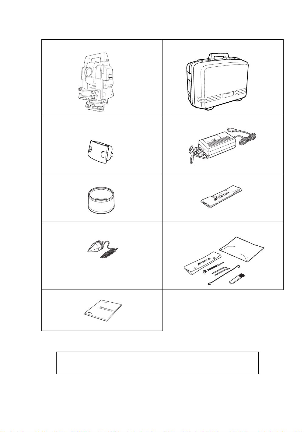
Standard Set Composition
The numeric al v alue in parentheses shows t he quantity.
GTS-820A series (with lens cap) (1) Plastic carrying case (1)
Battery BT-56Q (2) Battery charger BC-27BR or BC-27CR (1)
Sun shade (1) Plastic rain cove r (1)
FORE W ORD
Plumb bo b se t (1) Tool kit with c a se [ rod pi ns , Plum b bob hook, scre w -
Plumb bob hook is included
in the tool kit case.
Instruction manual (1)
(Make sure that all of the above items are with the instrument when purchased.)
Remarks:
1) Battery char ger BC- 27C R is for AC 230V us e and BC-27B R is for AC 120V use.
2) Plumb bob set and plumb bob hook are supplied for certain markets.
driver, cleaning brush ] (1)
9
Page 12
1 NOMENCLATURE AND FUNCTIONS
O
L
(
T
L
(
c
(
1 NOMENCLATURE AND FUNCTIONS
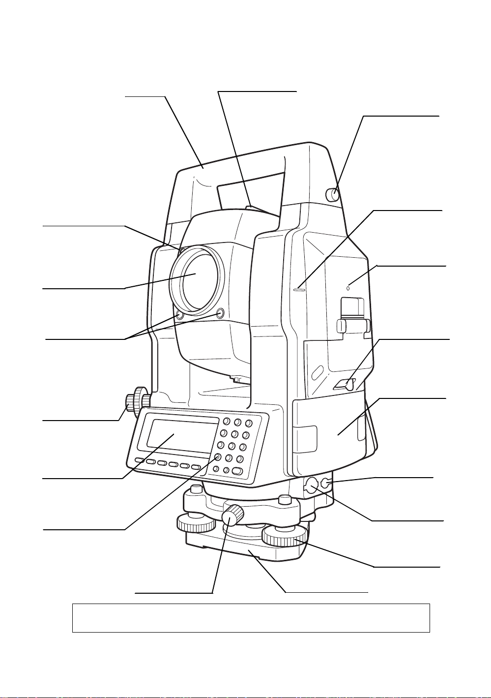
1.1 Nomenclature
Handle
aser aperture
for optical
ommunication)
bjective lens
aser aperture
for auto-tracking)
racking indicator
Sighting collimator
Handle fixing knob
Instrument height
mark
Instrument center
mark
Card cover lever
Battery BT-56 Q
Optical plummet
telescope
Display window
Only for GTS - 821A)
Operation keys
(Only for GTS-821A)
The caution labels are pasted up GTS-820A series which describe the warning of laser beam.
Refer to "Laser Safety" about label positions and their shapes.
Base fixing screw
Base (Model TR-5)
Power sup p ly
connector
Serial Signal
Connector-1(6pin)
Leveling screw
1-1
Page 13
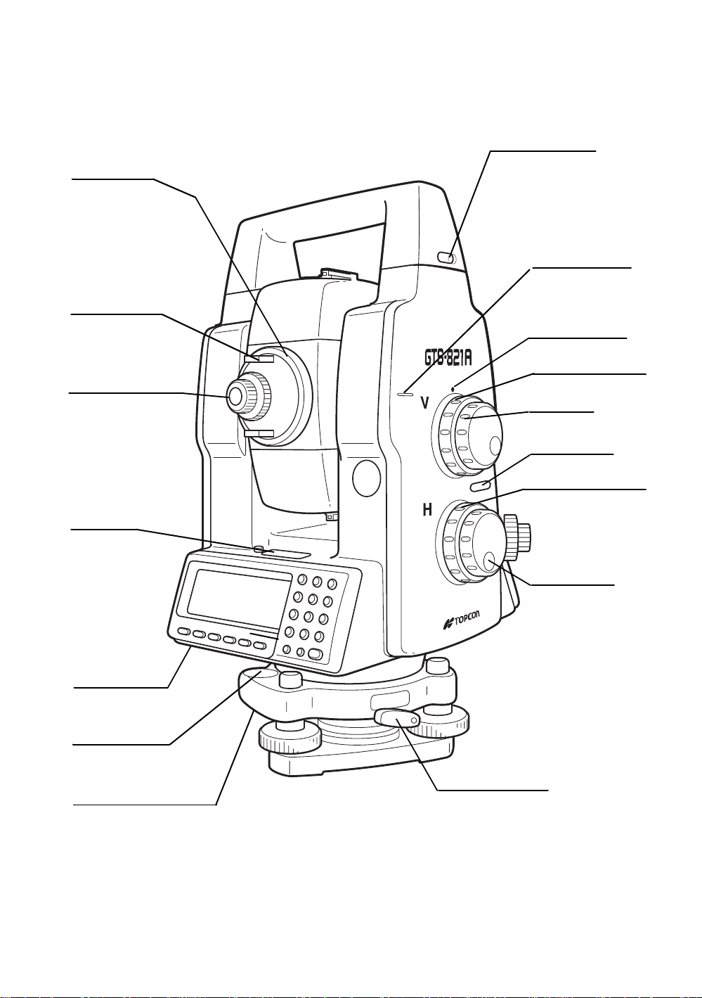
Telescope
focusing knob
1 NOMENCLATURE AND FUNCTIONS
Handle fixing knob
Instrument height
mark
Telescope grip
Telescope eyepiece
Plate level
Centronics
connector
Instrument center
mark
Vertical shuttle
Vertical jog
Power swi t ch
Horizontal shuttle
Horizontal jog
Circular level
Adjusting screws for
circular level
Tribrach fixing lever
1-2
Page 14
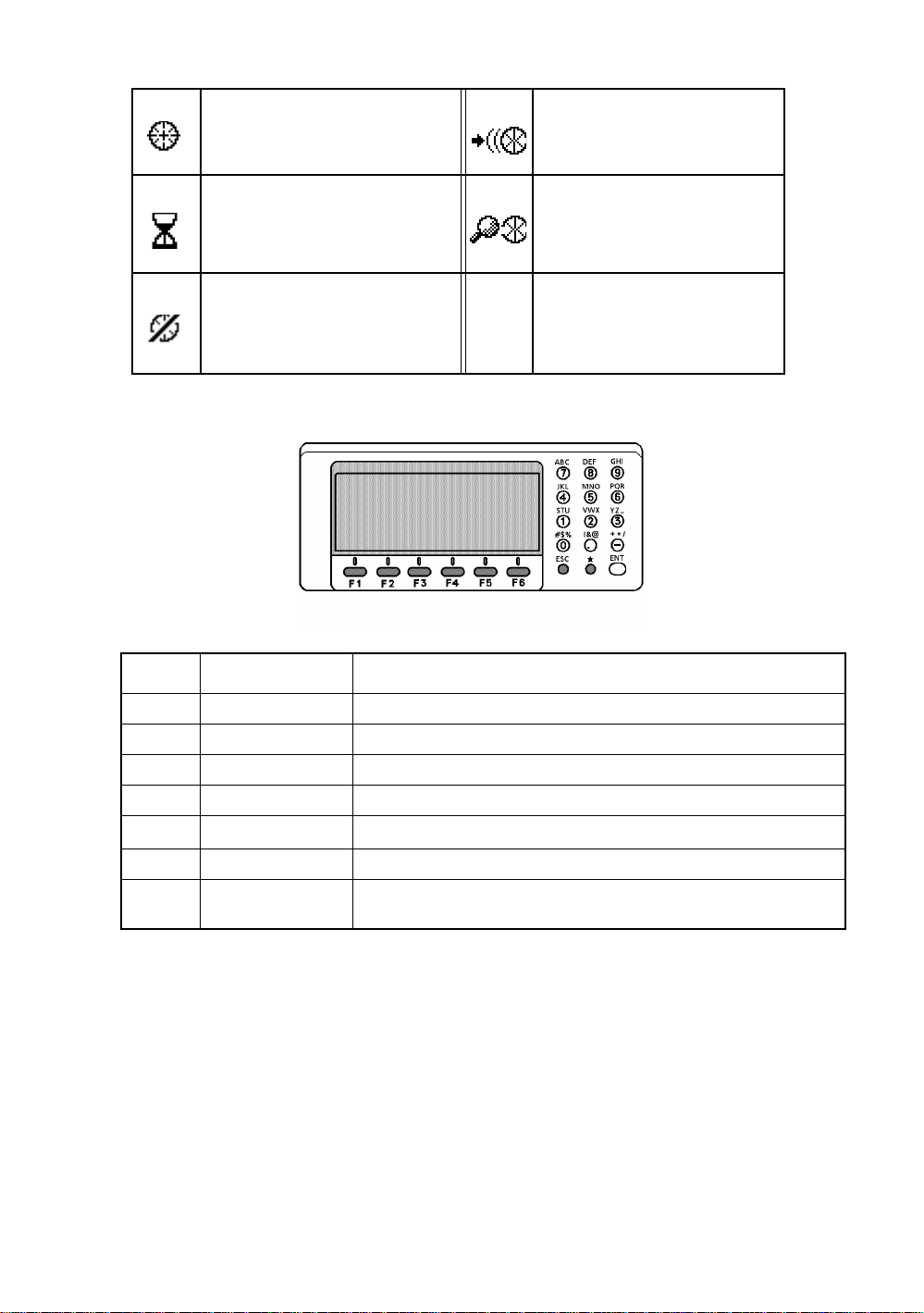
1.2 Display
Display
•
In general upper fo ur lines displ ay the mea suring data, and the
bottom line displays the soft key function which is changed by the measuring mode.
Contrast
•
The c ontras t and i ll umination of display w i ndow are ad justed by st a r (H) key.
Heater (Au t om atic)
•
The built-in heater keeps the display functional when the temperature goes below 0°C (32 °F). To
switch the heater ON or OFF, refer to Chapter 8 “PARAMETERS SETTING MODE”.
When the he ater i s ON a nd the temperat ure g o es belo w 0 ° C .(32 °F), the heater automatical ly
adjust the temperature to the display to keep it operating.
Example
•
1 NOMENCLATURE AND FUNCTIONS
V : 87°55'45"
HR: 180°44'12"
SD HD NEZ 0SET HOLD P1
Angle measure me nt mode
V-angle : 87°55’20”
H-angle : 180°44’12”
↓
V : 87°55'40"
HR: 180°44'12" PSM 0.0
SD: 12.345 PPM 0.0
(m) *F.R
MEAS MODE VH HD NEZ P1
Distance measurement mode
Horizontal-angle : 87°55’40”
Horizontal distance : 180°44’12”
Relative elevation :12.345m
Display marks
•
Display Contents Display Content
V V-angle * EDM working
V% Percent grade (m) Meter unit
HR H-angle right (f) Feet unit
HL H-angle l ef t F Fine mode
HD Horizontal dis t ance C Coarse mode (1mm)
VD Relative elevation T Tracking mode (10mm)
↓
SD Slope distance R Repeat meas ur ement
N N coordinate S Single measurement
E E coordinate N N-ti m es me as urem ent
Z Z coordinate ppm Atmospheric correction value
psm Prism constant value
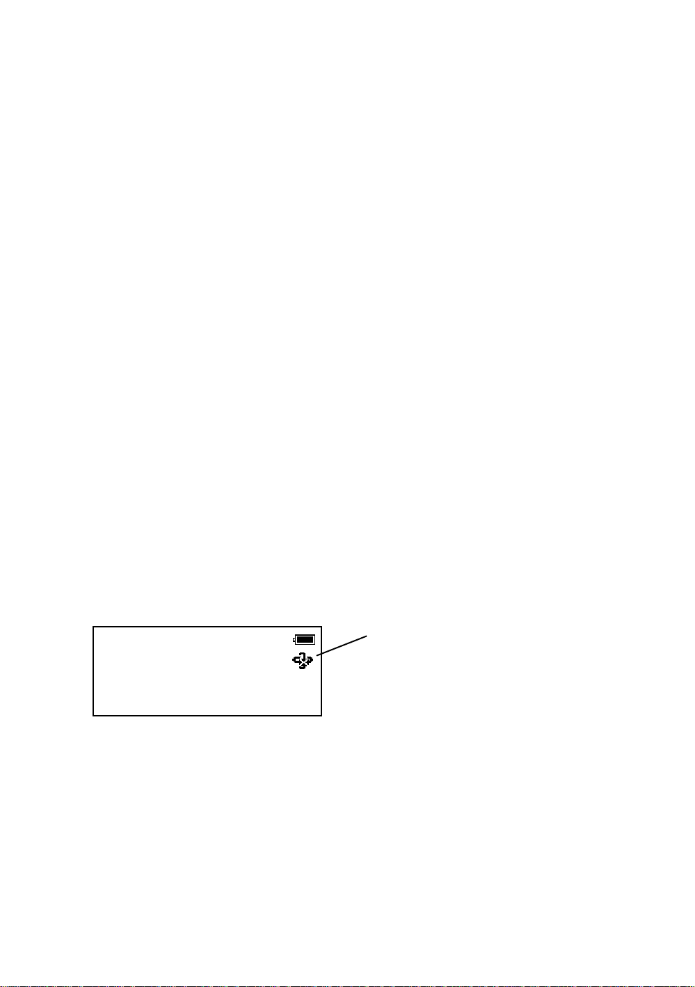
Battery Level Indicator
Refer to Section 2.4 “B attery Level
Indicator” for further information.
Rotation Indicator
Refer to Section 1.8 “Rotating
Method” for further information.
1-3
Page 15
l The symbol marks for Auto-tracking and Auto-collimating
1 NOMENCLATURE AND FUNCTIONS
Auto-collimating
Laser is emit ting
(
GTS-820A serie s is i n autocollimat ing stat u s.
Waiting (
GTS-820A serie s is i n waiting
status.
Failure in auto-collimating.
Laser is off
(
GTS-820A serie s could not find
the target prism dur ing aut o collimating.
Laser is emitting
1.3 Operat ing Key
Auto-tracking
)
)
)
Laser is emitting
(
GTS-820A series is in autotracking status.
Searching (
GTS-820A series is searching a
prism.
)
Laser is emitting
)
KEY NAME FUNCTION
F1~F6 Soft key Functions are according to the displayed message.
0~9 . - Numeric key Numeric Character Entry for Preset Data
A ~/ Alpha key Alpha Character Entry
ESC Escape key Escape to Previous Display or Menu
*
ENT Enter key End operation of data input and accepts data
POWER Power key
Star key Option al ins tr ume nt funct i ons
ON/OFF of power source.
(Power key is located on the side of the instrument.)
1-4
Page 16
1 NOMENCLATURE AND FUNCTIONS
1.4 Function Key (So ft K ey)
The Soft Key Functions are labeled on the bottom of display. Soft Key functions are different for each
measurement.
V : 87°55'45"5
HR: 180°44'12"5
SD HD NEZ 0SET HOLD
P1
↓
[F1] [F2] [F3] [F4]
V : 87°55'45"5
HR: 180°44'12"5
SD HD NEZ 0SET HOLD P1
TURN HSET R/L V/% TILT P2
Angle measuring
V : 90 10'20"5
HR: 120 30'40"5 PSM 0.0
HD: PPM 0.0
VD: (m) F.R
MEAS MODE VH SD NEZ P1
REC SO MEAN P2
Horizontal distance measuring
Page Display
Angle
measuring
SD F1 Slope distance measur ing mode.
HD F2 Horizontal distance measuring mode.
NEZ F3 Coordinate distance measuring mode.
0SET F4 Set horizontal angle to 0°00'00".
HOLD F5 Horizontal angle hold.
TURN F1 Turns the instrument to required angle automatically.
HSET F2 Preset a horizontal angle.
R/L F3 Changes hori zontal angle ri gh t or lef t.
V/% F4 Changes the disp l ay to vertical angle or percent of grade.
TILT F5
Soft
key
Sets the tilt function, ON/OFF.
If ON, the display shows tilt correction value.
Soft keys
↓
↓
↓
↓
[F5]
[F6]
V : 90°10'20"5
HR: 120°30'40"5 PSM 0.0
SD: PPM 0.0
(m) F.R
MEAS MODE VH HD NEZ P1
TURN SO MEAN m/ft P2
Slope distance measur ing
N : 12345.6789
E : -12345.6789 PSM 0.0
Z : 10.1234 PPM 0.0
(m) F.R
MEAS MODE VH SD HD P1
↓
TURN HT MEAN P2
Coordinate measuring
Function
↓
↓
↓
1-5
Page 17

1 NOMENCLATURE AND FUNCTIONS
Page Display
Slope
distance
measuring
Horizontal
distance
measuring
Coordinate
measuring
Soft
key
MEAS F1
Starts sl ope distance mea surement mode.
Changes Continuous/ N-times (single) measurement mode.
Function
MODE F2 Chang es Fine / Coarse(1mm) /Co arse(10 mm) m ode.
VH F3 Angle me asurement mode.
HD F4
NEZ F5
Horizontal distance measurement mode. Displays the horizontal distance
data after N-times or single measurement.
Coordinate measurement mode.
Displays the coordinate after N-times or single measurement.
TURN F1 Turns the instrument to required angle automatically.
SO F2 Stake out measurement mode.
MEAN F3 Sets the number of N-time measurement.
m/ft F4 Changes distance measurement unit to meter or feet.
MEAS F1
Starts horizontal d i stance measurement mode.
Changes continuous/ N-times (single) measurement mode.
MODE F2 Chang es Fine / Coarse(1mm) /Co arse(10 mm) m ode.
VH F3 Angle me asurement mode.
SD F4
NEZ F5
Slope distance measuri ng mode.
Display the sl ope distance af ter N-times or si ngl e measureme nt.
Coordinate measurement mode.
Displays the coordinate after N-times or single measurement.
TURN F1 Turns the instrument to required angle automatically.
SO F2 Stake out measurement mode.
MEAN F3 Sets the number of N-time measurement.
m/ft F4 Switches meter or feet unit.
MEAS F1
Starts coordinate measurement mode.
Changes continuous/ N-times (single) measurement mode.
MODE F2 Chang es Fine / Coarse(1mm) /Co arse(10 mm) m ode.
VH F3 Angle me asurement mode.
SD F4
HD F5
Slope distance measuri ng mode.
Display the sl ope distance af ter N-times or si ngl e measureme nt.
Horizontal distance measurement mode. Displays the horizontal distance
data after N-times or single measurement.
TURN F1 Turns the instrument to required angle automatically.
HT F2 Input Instrument / prism height values.
MEAN F3 Sets the number of N-time measurement.
m/ft F4 Switches meter or feet unit.
SET F5 Pre-set instrument coordinate values.
1-6
Page 18
1 NOMENCLATURE AND FUNCTIONS
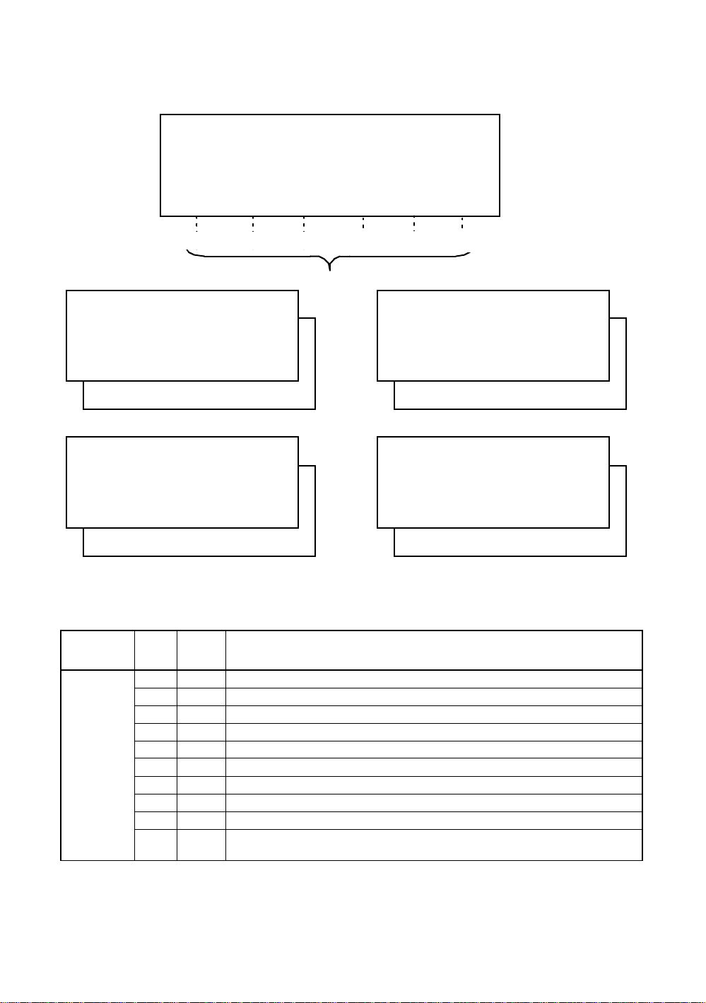
1.5 Star key (*key) mode
Press the (H) key to view the instrument options. Since there are three screens of options, press
[F6](1↓) soft key to view the next screen.
The following instrument options can be selected from the (H):
Screen One
•
1)View Dat e & Time
2)Auto-tracking [F1]
3)Auto-collimating [F2]
4)Set the parameters for Auto-tracking.[F3]
5)Auto- inversio n [F4]
6)Electric circular graphic display[F5]
Screen Two
•
7)Adjustment the co ntrast of the displa y [F1 & F2]
8)Turn the back light of the display ON/OFF [F3]
9)Reticle illumination---Off / Low / Medium / High [F4]
10) View free memory for internal and card memory [F5 ]
Screen Th ree
•
11) The light acceptance quantity level (signal level) is displayed.[F1]
12)Set the Temperature, Pressure, Atmospheric Correction Value (ppm), and Prism Constant
Va lue ( PSM ) [F2]
13)Turn the Tracking Indicator option ON/OFF [F3]
Auto-tracking
Auto-collimating
Set parameter for Auto-trackin g
Auto- inversion
Electric circular graphic display
Date & Time
Cont rast adjustment
Displaying
Signal Level
2003-10-10 14:30:40
1
↓
View free memory for Card/Internal Memory
Back Li ght of Displ ay
Reticle illumination
2003-10-10 14:30:40
2
↓
Set the Temperature, Pressure, Atmospheric Correction
Value (PPM), and Prism Constant Value (PSM)
Trac ki ng indicator
2003-10-10 14:30:40
3
↓
Screen 1
Screen 2
Screen 3
1-7
Page 19
1 NOMENCLATURE AND FUNCTIONS
1) View Date & Time
The date and time can be viewed on both screens. To change the displayed order of the date, (Date/
Month/Year), (Month / Date / Ye ar) or (Year/Month/Date), see Chapter 8 “PARAMETERS SETTI NG
MODE” .
To set the date a nd time, see Chapter 9 “CHECK AND ADJUSTMENT”.
2) Turn the auto-trackin g ON/OFF
Press the [F1] key to start auto-tracking. See Section 3.1 “Automatic Tracking” .
3) Turn the auto-collima tin g ON/OFF
Press the [F2] key to start auto-col lima ting. See Section 3.2 “Automatic Collimation” .
4) Set the parameters for the auto-tracking
A proper setting for each parameter such as tracking pattern, tracking range, waiting time, tracking
speed and trac ki ng se nsit ivity. See Section 3.4 “Set ting Par a me ter s for Aut o -Tracking” .
5) Auto Inversion
Pressing the [F4] key causes the instrument to reverse and turn the telescope and instrument
automatically.
l To stop auto rotating in case of emergency, press any keys except POWER key.
l During auto rotation, do not disturb the instrument.(Stopping the rotation with a touch of the hand).
Such action may cause trouble or harm to instrument or operator.
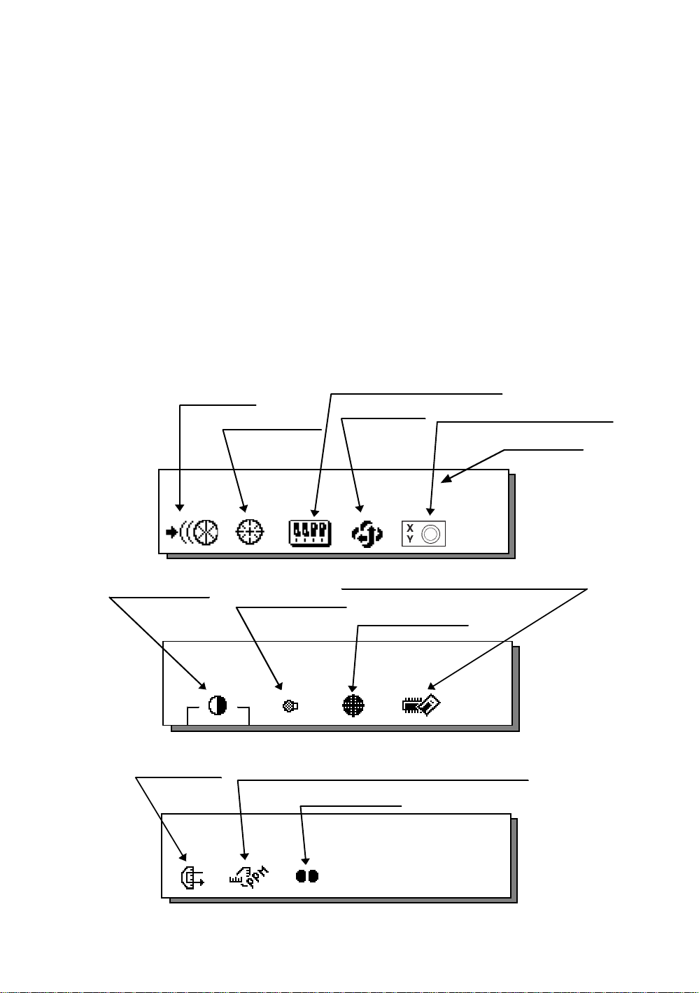
6) Electr ic circular level graphic display
Electric circular level can be displayed by graphic. This function is good for level the instrument when
the circular level is difficult to see directly.
Press the [F5] key to display the graphic.
In the displays of reverse side, the graphic bub ble mov es in reverse.
X:------------Y:-------------
Rotate the leveling screws while observing the display.
After leve ling, press [F1]. The display cha nge s to the prev ious mode.
7) Adjustme nt the contrast of the dis p lay
This enable you to adjust the contrast of the display.
Press the [F6] key to get to Screen 2 on the display.
Press the [F1] or [F2] key to brighten or dim the display.
8) Turn the display back light ON/OFF
When the back light is OFF, the light bulb icon is dark.
Press the [F6] key to get to Screen 2 on the display.
To turn the back light ON, press the [F3] key. Press [F3] again to turn the back light OFF.
OFF ON
X:+0°00'00"
Y:+0°00'00"
1-8
Page 20
1 NOMENCLATURE AND FUNCTIONS
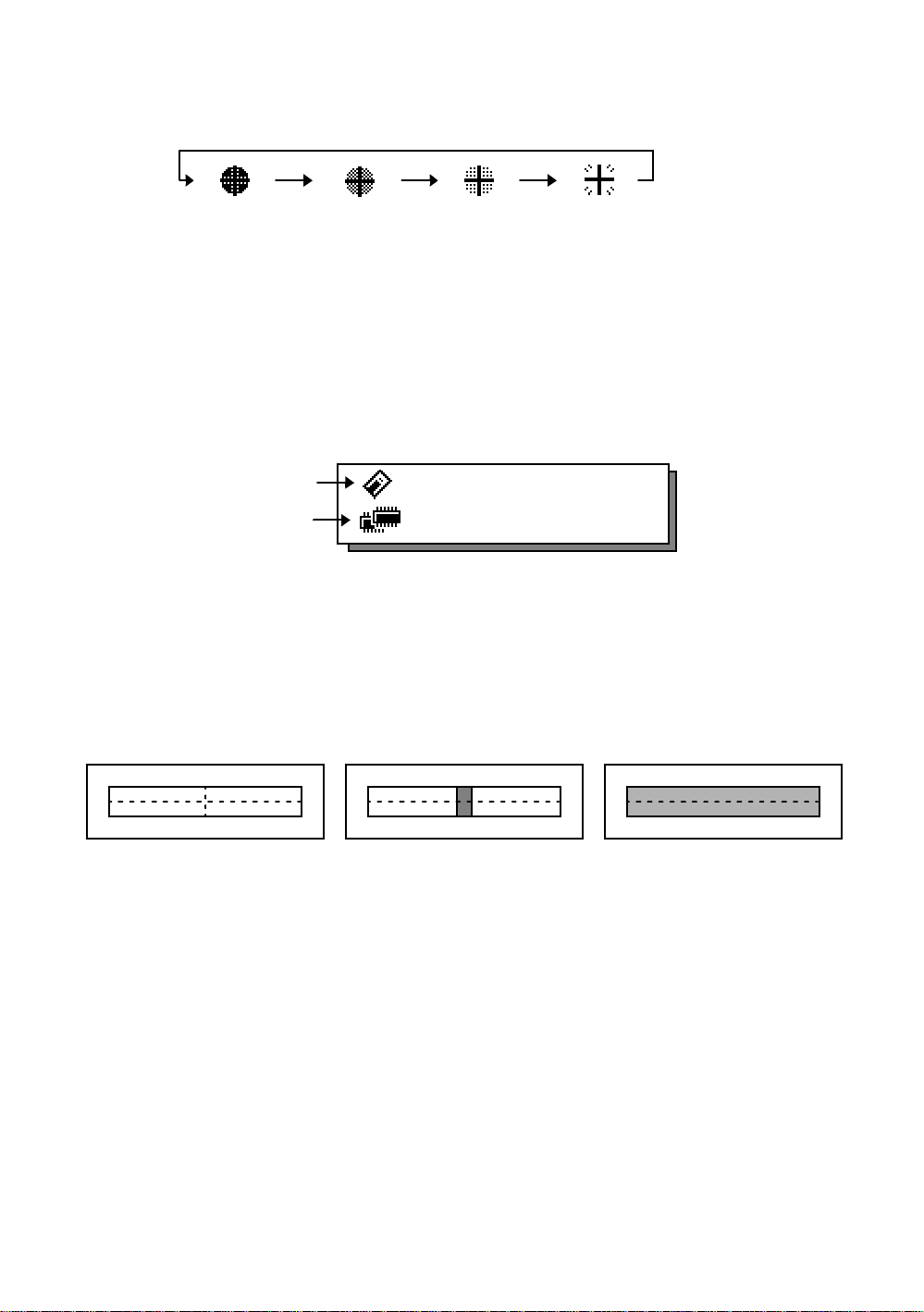
9) Reticle illumination (OFF/Low/Middle/High)
Press the [F6] key to get to Screen 2 on the display. Press the [F4] key to turn the reticle illumination
ON. Continuing to press [F4] will change the intensity options.
OFF
10) View free memory
The amount of free memory for the card or internal memory can be displayed.
Press the [F6] key to get to Screen 2 on the display.
Press the [F5] key to view free memory.
The card memory icon (top left side of the display) shows the size of the card and the amount of free
memory. The second icon shows the amount of free internal memory.
Card Memo r y
Internal Memory
See Chapter 6 “MEMORY MANAGE MODES”, for further options and instructions.
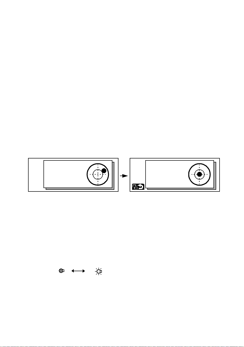
11) Set audio mode
The light acceptance quantity level (Signal level) is displayed in this mode.
When reflected light from the prism is rece i ved , a buzzer soun ds. This function is good for easy
collimation when the target is difficult to find.
Press the [F1] key on scre en 3.
The received return signal level is displayed with bar graph as follows.
Low
Middle
512KB
High
315KByte
1882KByte
No light acceptance
(1) To stop the buzzer, see Chapter 8 “PARAMETERS SETTING MODE”.
(2) Also, it is possible to display the signal level in Distance Measuring Mode.
12)Setting Temperature, Pressure, Atmospheric correction value (ppm), Prism constant value
(PSM)
The temperature, pressure, PPM, and PSM can be viewed by pressing the [F2] key on screen 3 .
The received return signal level is displayed with bar graph as follows.
Refer to Chapter 10 “SETTING THE PRISM CONSTANT VALUE” and Chapter 11 “SETTING
ATMOSPHERIC CORRECTION”, for further instructions.
Minimum quantity level
Maximum quantity l evel
1-9
Page 21
1 NOMENCLATURE AND FUNCTIONS
13)Tracking Indicator
A man who is staying on line with t he direc t ion of GTS-820A series or automatic tracking status by
emitted LED light (orange color) from GTS-820A series.
Operation
•
Pressing [F3] key on screen three functions Tracking Indicator. The tracking indicator status will be
changed a cco rding to the typ e of auto tra cki n g m ode an d i ts co ndi tions. A man from the prism side can
recognize t he status of instrument.
When angle measuring value turns stable during track ing still object, the tracking indicator changes
from quick con tinu ous fla shing to qu ick inte rm itten t flashing. S o you can dec ide fro m the sign of fla shing
for recording data timing at one person surveying.
OFF ON
Meaning of Tracking Indicator ON or Flashing
Trac ki ng Indicator Tracking status of instrument
Continuous ON Wait status
Slow flashing Manual mode
Quick continuous flashing
Quick intermittent flashing
In case angle measuring value is instable during auto tracking
mode.
In case angle measuring value is stable during auto tracking
mode.
l The function of the Tracking Indicator will be used as a guide to know the status of GTS-820A
series from the prism side. This is not a function to determine precise collimating for measuring.
l The quality of its results will depend on the weather conditions and the use's eyesight.
l Sometimes happens d i fficult y of seeing t he t r ack i ng ind i cator becaus e too mu ch bright of the beam
for tracking.
l Using Tracking Indicator mode will result shorter in reduced time out of the battery.
1-10
Page 22
1 NOMENCLATURE AND FUNCTIONS
1.6 Auto Power Off
The Auto Power OFF feature can be set from 1 to 99 minutes. If no keys are pressed within the set
time, the Auto Power OFF will automatically turn the instrument OFF in order to save the battery time.
See Chapter 8 “PARAMETERS SETTIN G MODE”, for furth e r inst ru ct ions.
1.7 Data Output
When GTS-820A series receives data output command from an external connected
device, the measured data will be output by GTS-820A series. Select from the following
2 ways for the output. (For setting, see Chapter 8 “PARAMETERS SETTING MODE” .)
REC-A : The measurement is started and new data is output.
REC-B : The data being displayed is output.
1.8 Rotating Method
1.8.1 Rotating by H/V Shuttle and H/V Jog
H/V shuttle or H/V jog can be used to rotate the instrument manually. The shuttle movement or
displacement is proportional in speed and size of angle desired. A small, slow turn of the shuttle will
result in a slow sma ll angl e displaced. L i kew ise, a larger abr up t turn of the shuttle will result in a coarse
angle displacement. H/V jog can be used for accurate collimating of the target much like a standard
tangent screw.
1.8.2 Auto Inversion
Pressing the [F4] key in Star Key mode causes the instrument to reverse and turn the telescope and
instrument automa tically.
l To stop auto rotating by auto inversion key in case of emergency, press any keys except POWER
key.
l During auto rotation, don't disturb the instrument.(Stopping the rotation with a touch of the hand).
Such action may cause trouble or harm to instrument or operator.
See Section 1.5 “Star key (*key) mode” for further instructions.
1.8.3 Rotating automatically to a required Horizontal and Vertical angle
In Standard Measu rem ent Modes, the instrument can be rot ate d autom at ically by inpu t a required
horizontal and/or vertical angle.
For further instructions, see Section 4.1.5 “Automatic Rotation to a Required Horizontal and Verti cal
Absolute Angle” .
V : 87°55'45"5
This mark will appear while the
instrument is rotating automatically.
HR: 180°44'12"5
SD HD NEZ 0SET HOLD P1
↓
1-11
Page 23
1 NOMENCLATURE AND FUNCTIONS
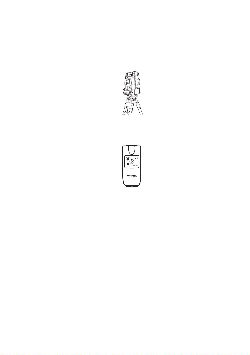
1.9 Using together with RC-2II Remote Control System
Using together with RC-2II Remot e Con tr ol System makes it possibl e to opti c al communi cat e betwe en
the inst rument and rem ot e controller RC-2RII, the pris m side. This gi ves easy operat ion by one man
surveying in applying programs.
Also connecting data collector to remote con troller, you can manage communication reciprocally
between the instrument and direct to data collector.
Turn-round function
You can turn the GTS-820A series round to the remote controller RC-2RII side easily by [Turn-round]
key of the remote controller RC-2RII. This function helps to increase one man surveying efficiency.
RC-2RII
See to Section 5.7 “External Link” and Chapter 8 “PARAMETERS SETTING MODE” for further
information.
l Set the transmit path to " RC".
l Set the transmit channel same as RC-2RII side.
l To execute transmission, set the remote in Programs mode to [Remote].
1-12
Page 24
1 NOMENCLATURE AND FUNCTIONS
1.10 Using connectin g with Personal C om pu ter (P C )
The auto-tracking function or auto collimating function makes easy remote control of the instrument
from PC. The followings are the main communication commands and explanations. How to
communicat e or more information s of communica ti on com ma nd, you can see the i nterface manua l
which provided optiona ll y.
Commands Action of GTS-820A series
Transmit
command
Mode setting
Transmit command for measured data
Transmit command for tracking mode
Transmit command for battery level The battery level will be out put.
Transmit command for coordinate of
instrument point
Transmit command for tracking
parameter
Setting of angle me asurement
Setting of distance measuremen t
Setting coor dinate of instrument point Setting the coo rdinate of instru me nt poi nt .
Setting the track i ng para me t er
Each measured data will be out put
according to t he command type.
The status of Aut om at ic Tr acking mode
will be out put.
Setting coordinate of instrument point will
be ou t put.
Each setting tracking parameter of
instrument will be out put according to the
command type.
Each selecting mode in horizontal angle
or angle measurement can be decided
according to t he purpose of comman d.
Setting the measurement mode for
distance me asurement.
Setting each tracking parameter
according to t he command.
Action
T.I. ON / OFF ON / OFF of Tracking indicator.
Rotating command Rotating of setting angle.
Inversion Inversion movement.
Setting trac ki ng mo de
Setting from automatic tracking mode to
each command mode.
1-13
Page 25
2 PREPARATION FOR MEASUREMENT
2 PREPARATION FOR MEASUREMENT
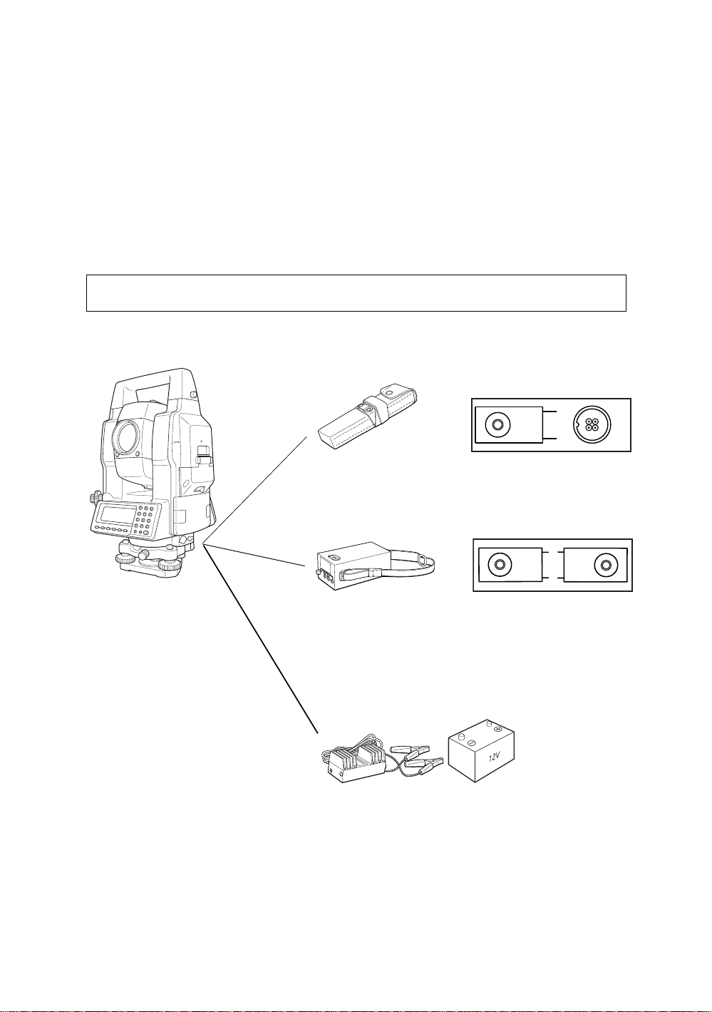
2.1 Power Connectio n
(unnecessary if on-board Ni-MH battery BT-56Q is used)
See below for connecting the external battery pack.
Battery pack BT-3Q
l
Power cord , PC-5 is used.
Large capacity battery pack BT-3L
l
Power cord PC-6 is used.
l When using a external battery, the rechargeable battery BT-56Q should be attached
(The instrument will lack in balance if the internal battery BT-56Q is removed.)
The external batter y and th e inter nal ba ttery can be used at the same time. The GTS- 820 A seri es
will select a battery due to the battery remaining automatically.
PC-5
Connector ends
BT-3Q
PC-5
PC-6
PC-5 or PC-6
BT-3L
2-1
AC-6
PC-6
External 12V Battery
Page 26
2 PREPARATION FOR MEASUREMENT
Leveling screw C
9
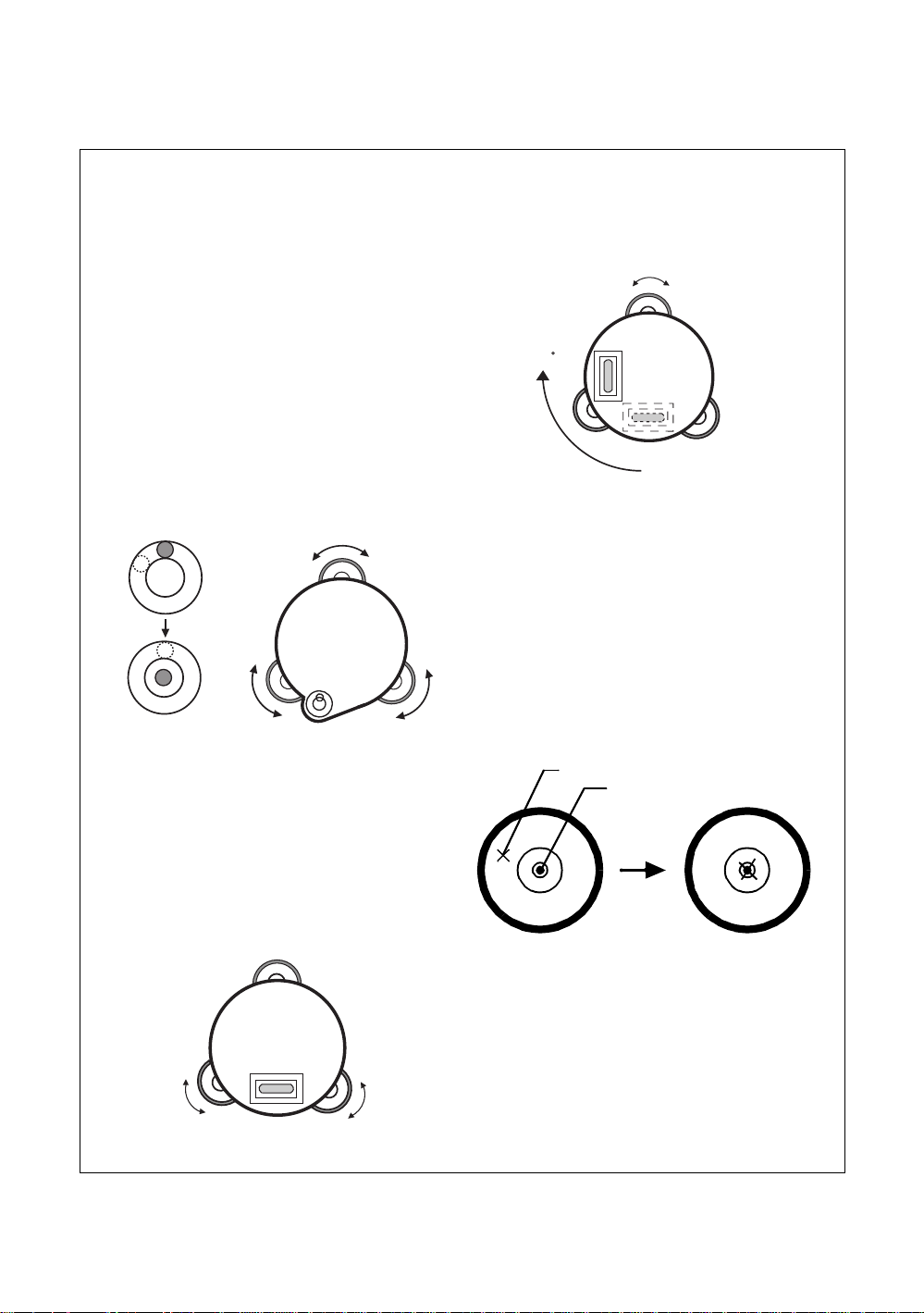
2.2 Setting Instrument Up For Measurement
Mount the instrument to the tripod. Level and cente r the instr um en t pre cise l y to ins ur e the best
performance. Use tripods with a tripod screw of 5/8 in. diameter and 11 threads per inch, such as the
Type E TOPCON wide- frame wooden tripod.
Reference: Leveling and Centering the Instrument
1. Setting up the Tripod
First, e xtend t he ex tens ion legs to s uita ble l engths
and tighten t he screws on thei r midsec ti ons.
2. Attaching the Instrument on the Tripod
Head
Place the instrument carefully on the tripod head
and slide the instrument by loosening the tripod
screw. If the plumb bob is p osit ioned right over the
center of th e point, slightl y ti gh t en the tri po d
screw.
3.
Roughly Leveling the Instrument by Using the Circular
Level
1 Turn the leveling screws A and B to move the
bubble i n t he c i rcular level. The bub ble is now
located on a line perpendicular to a line
running thr oug h the cen ters of t he two l evel ing
screws be i ng adjusted.
Leveling
screw A
2 Turn the leveling scre w C to bring the bubble
to the center of the cir c ular level.
4. Centering by Using the Plate Level
1 Ro tat e the instrument horizontally by using
the Horizontal motion/c l am p scr ew and place
the plate level parallel with the line connecting
levelin g screw s A and B, and then brin g the
bubble to the center of the plate level by
turning leveling screws A and B.
Leveling screw B
2 Ro t ate the instrument 90° (100g) around its
vertical axis and turn the remaining leveling
screw or C to center the bubble once more.
Leveling screw C
0
3 Repeat the procedures 1 and 2 for each 90°
(100g) rotation of the instrument and check
whether the bubble is corr ectly centere d for all
four points.
5. Centering by Using the Optical Plummet
Telescope
Adjust the eyepiece of the optical plummet
telescope t o your eyes ight.
Slide the instrument by loosening the tripod
screw, place the point on the center mark, and
then tighten the tripod screw. Sliding the
instrument carefully not to rotate that allows you
to get the least dislocation of the bubble.
Point
Center mark
6. Completely Leveling the Instrument
Leveling the instrument precisely in a similar way
to 4. Rotate the ins trum ent and check to see that
the bubble is in the center of the plate level
regardless of telescope direction, then tighten the
Leveling
screw A
Leveling
screw B
tripod screw hard.
2-2
Page 27
2.3 Power Switch Key ON
)
g
d
e
Power ON
2 PREPARATION FOR MEASUREMENT
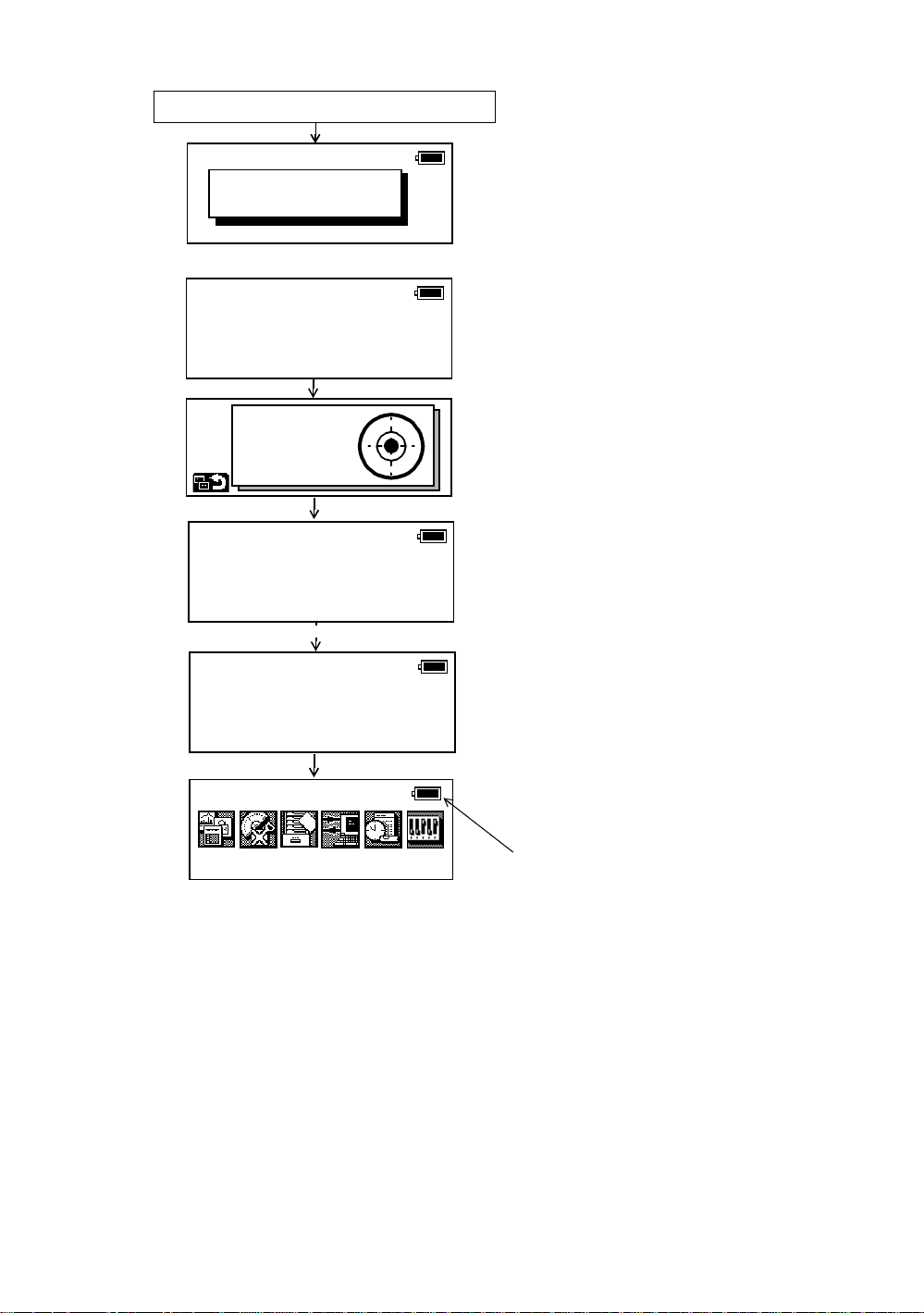
1) Confirm the instrument is leveled.
2) Turn the power switch ON.
Input a password
[ ]
Self check mode
ESC
X:+0°00'00"
Y:+0°00'00"
Self checking ...
[ 1/6 ]
Self checking ...
[ 6/6 ]
3) Type your password.
Self checki n g mode will disp lay.
To skip the self checking , pr ess [F1 ] (ES C
key.
Level the ins trumen t by turning t he leveli n
screws.
When the leveling is within ±30" and
stable, the self checking will start.
The instrument will turn automatically and
the tilt sensor offset value will be measure
and me mo rized.
2003-10-10 14:30
Prog
Std Mem
Main menu icons
Self checking option
l
The self checking f unc ti on is to che ck i nternal communicat ion and ti lt sens or of f set value.
When ambient tem per at ur e is cha nged or the i nstrument is not balanc ed by its int e rnal battery is
attached or detach ed, the self che cki n g is reco mm end ed.
Password option
l
Setting a password (Maximum 10 digits number) and activating ON of password option can be helpful
to avoid miss operation by unauthorized operator.
Setting password option is necessary to use this function.
To set password option, see Chapter 8 “PARAMETERS SETTING MODE” .
Choosing the first mode when turning on the instrum ent
l
You can choose the first mode from the following modes when turning on the instrument.
1. Main Menu 2. Standard Measurement Mode 3. External Link
See Chapter 8 “PARAMETERS SETTING MODE” .
ON/OFF of a self check function can also be chosen.
l
See Chapter 8 “PARAMETERS SETTING MODE” .
l Confirm the battery power remaining on the display. Replace with charged battery or charge when
battery level is low. Refer to Section 2.4 “Battery Level Indicator” .
Comm
Adj
Para
After checki ng, the mai n me nu icon s wi ll b
shown.
Battery Power Remaining Display
2-3
Page 28
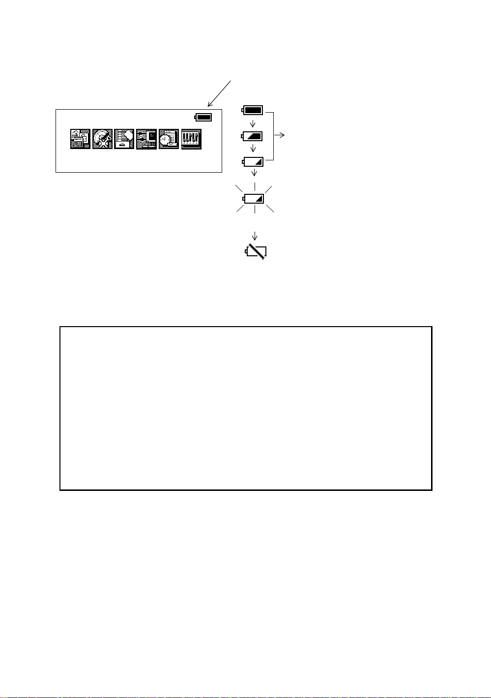
2.4 Batter y Level Indicator
The battery power indicator shows the level of battery strength.
Indicates Battery Power Remaining
2003-10-10 15:30:40
2 PREPARATION FOR MEASUREMENT
Measurement is possible.
Prog
Note:
1) The battery operating time will vary depending on the environmental conditions, such as
ambi ent temper ature, chargin g time, and t he number of tim es charging and discharging the
battery.
2) In low temperature (especially while the heater of display is working), the battery operating
time will shorten to one-half of normal temperature use.
3) The indicator for battery power remaining shows the power level during each measurement
mode. The condition indicated for the battery power remaining in the angle measurement
mode may not be adequate to measure a distance. Changing from angle mode to distance
mode during a poor battery condition may cause the EDM not to measure a distance.
We recommend that you check the battery condition before going into the field.
4) Also note, when changing from one measurement mode to another, the battery indicator may
not show a decr eas e or an i ncr ease i mm ediately. The batt ery i ndicator syste m was desi gne d
to show the general condition for the battery strength. It does not respond instantly.
5) For more information on battery usage, refer to Chapter 13 “POWER SOURCE AND
CHARGING” .
Mem Comm
Std
* Battery power remaining display is omitted in this manual.
Adj
Para
Blinking
The power is p oor. The batter y sho ul d be
recharged or replace the battery.
(Angle me asurent can only be possi ble,
the auto-collimating, auto-tracking and
distance maesurenat can not be
possible.)
Measurement is impossible. Need to
recharge or replace the battery.
2-4
Page 29
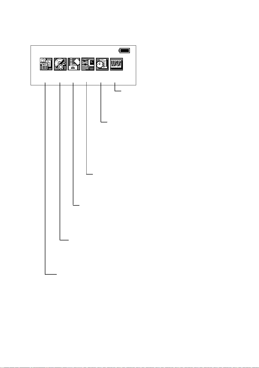
2.5 Main Menu Icons
The main menu icons are as follow s.
Select t he men u by pressi ng soft k eys ([F1]~[F6]).
2003-07-10 15:30:40
2 PREPARATION FOR MEASUREMENT
Prog
Std
Mem Comm
Adj
Para
PARAMETERS SETTING MODES
The PARAMETE RS SETTING MODES are
stored in memory once the instrument is OFF.
(See Chapter 8 “PARAMETERS SETTING
MODE”.)
ADJUSTMENT MODES
Used for checki ng and adjust m ent.
l Systematic errors adjust m ent for com pensa tion.
l Show compensation value s of systemati c erro rs of
instrument
l Set Date & Time
l Set instrument constant value
l Reference frequency of EDM
l Optic Axis for Auto-tracking
(See Chapter 9 “CHECK AND ADJUSTMENT”.)
COMMUNICATION MODES
l Set communica ti on with external instrument
l Input/Output a data file
l Load application program.
(See Chapter 7 “COMMUNICATION MODES”.)
MEMORY MANAGE MODES
l Display memory status
l Pro tect/ Er as/Renam e/Copy File s,
l Initialize a card or internal memory.
(See Chapter 6 “MEMORY MANAGE MO DES” .)
STANDARD MEASUREMENT MODES
l Angle measurement
l Distance measurement
l Coordinate measurement
(See Chapter 4 “STANDARD MEASUREMENT MO DE ” .)
PROGRAM MODES ( APPLICATION MEASUREMENT)
l Set a direction angle for h orizontal orientation
l Retain Coordinate (STORE-NEZ)
l Remote elevation measuremen t
l Missing line me asurement
l Line measurement
l External link
l Off set measurement
(See Chapter 5 “PROGRAM MODES” .)
2-5
Page 30
2 PREPARATION FOR MEASUREMENT
V
W
X
S
P
O
T
Q
D
U
R
|
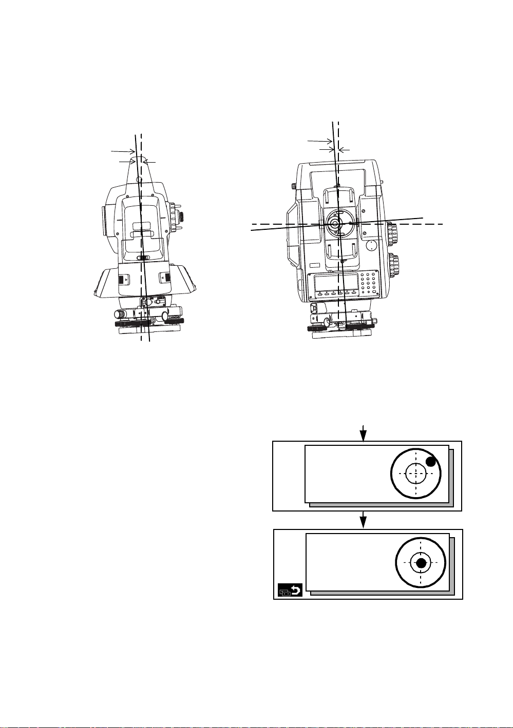
2.6 Vertical and Horizontal Angle Tilt Correction
When the tilt sensors are activated, automatic correction of vertical and horizontal angle for
mislevelment is displayed.
To ensure a precise angle measurement, tilt sensors must be turned on. The display can also be used
to fine level the instrument. If the (TILT OVER) display appears the instrument is out of automatic
compensation range and must be leveled manually.
Zenith
Standing axis
Standing axis
Inclination of the standing
axis in the X direction
Zenith
Inclinati on of the standing
axis in the Y direction
X
U
R
|
Trunnion axis
Horizontal
W
V
T
S
Q
P
D
O
l GTS-820A seri es compensates bot h th e vert i cal angle and the hor i zontal angle r eadings due to
inclination of the standing axis in the X and Y directions.
l For more information about dual axis compensation, see Chapter “APPENDIX” “Dual Axis
Compensation”.
When the instrume nt t il ted ove r correc t ion
range.
X:
Y:
Rotate the leveling screws and level the
instrument.
After leveling (when each axis is within ±1'30 "),
the display returns to the previous mode
automatically.
X:+0°00'00"
Y:+0°00'00"
X,Y tilt correction range : within ±4'
l The display of Vertical or Horizontal angle i s unst able when i nst ru me nt is on an uns ta ble stage or a
windy day. You can turn off the auto tilt correction function of V/H angle in this case. To set TILT
correct ion mod e ON/O FF, refer to next page or Chapter 8 “P AR AME TE RS SETTI N G MODE ”.
2-6
Page 31

Setting Tilt Correction by Soft Key
l
Enable you to select tilt ON/OFF function on page 2.
The setting performed here will be me morized after powering OFF.
[Example] Setting X,Y Tilt ON
Operating procedure Option Display
1
Press [F6] key to get the function page 2.
2 PREPARATION FOR MEASUREMENT
V : 87°55'45"
HR: 180°44'12"
[F6]
2
Press [F5](TI LT) key.
Current setting is displayed. *1
3
Press [F2]( ON- 2) key.
The display sh ow s t ilt cor r ection value .
4
Press [F1] key.
The display returns previous mode.
*1) Pressing [F6](ESC) key, the display returns previous mode.
l The tilt sensor setting will be stored in memory when the instrument is turned OFF.
The tilt sensor option can al so be changed in t he Parameter Setting Modes. When you change t he tilt
sensor option in the angle measurement mode, it will change in the Parameter Setting Modes and visa
verse.
[F5]
[F2]
[F1]
SD HD NEZ 0SET HOLD P1
REC HSET R/L V/% TILT P2
TILT ON (V)
ON-1 ON-2 OFF ESC
X:+0°00'00"
Y:+0°00'00"
2.7 Compensat ion of Systematic Error of Instrument
1) Error of vertical axis (X,Y tilt sensor of f se t )
2) Collimat ion err o r
3) Erro r of ve r tical angle 0 datum
4) Error of horizontal axis
The above mentioned errors can be compensated by software, which calculated internally
according to each compensation value.
Also these er rors can be compensat ed by software collima t ing one sid e o f the telescope t hat i s
carried out to delete the error by turning in normal and reverse both sides of telescope so far.
↓
↓
l To adjust or reset the above compensation value, see Chapter 9 “CHECK AND ADJUSTMENT” .
l Enable you to st op this function, se e Chapter 8 “PARAMETERS SETTING MODE” or Chapter 9
“CHECK AND ADJ U STMEN T” .
2-7
Page 32

2 PREPARATION FOR MEASUREMENT
2.8 Resume Mode ON/OFF
The Resume mode will memorize the last display or mode when the power is turned OFF.
When the power is turned bac k ON, the last display or mode will be shown.
The Resume mode option only appears when the power is OFF.
Power switch key OFF
Power off
Resume mode
OFF ON ESC
[F1] [F2]
Pressing [F1](OFF) key or [F2](ON) key, select the resume mode.
2.9 How to Enter Numerals and Alphabet Letters
Alpha and numeri c charact er k ey entr y is simple and quick from the key board.
[Example] Renaming a file in the Memory Manager Modes.
Operating procedure Option Display
Rename
Old name [TOPCON .DAT]
New name [
1
Press [F1](Alpha) key to be entering alphabet
letter mode.
2
Enter Alphabets. *1)
Type “H”
Move cursor
Type “I”
Type “L”
Type “
”
3
Press [F1](Num) key to be entering numeric
mode.
Input “104”
[F1]
[9][9]
[F4]
[9][9][9]
[4][4][4]
[3][3][3]
[F1]
[1][0][4]
Alpha SPC ← →
Rename
Old name [TOPCON .DAT]
New name [HIL
Num SPC ← →
Rename
Old name [TOPCON .DAT]
New name [HIL
]
]
104 ]
Alpha SPC ← →
4
Press [ENT] when complete.
*1) When the same alpha key is to be typed two or more times consecutively, press [F4](→) key between
characters. This moves the cursor to the right.
*2) Extensions can not be changed.
[ENT]
2-8
Page 33

2.10 Memory Card
How to i n sert a memor y card
2 PREPARATION FOR MEASUREMENT
1) Pull the ca rd c over lever to open the
card cover.
2) Insert a memory card until the card
guide is up.
3) Close the card cov er.
Card cover lever
Card guide
Memory card
How to extract a memory card
1) Pull the card cover lever to open the card
cover.
2) Pull down the card guide.
3) Extract the memory card.
Card guide
2-9
Page 34

2 PREPARATION FOR MEASUREMENT
2.11 Inclination of Prism and Measuring Error
For the best results, aim or point prism s in the di recti on of the GTS-820 A series so t hat maximum signal
can be returned to the instrument. Sighting prism obliquely because of inclined settings, may result in
measuring errors. These errors will be proportional to the misalignment as showing in following graphs.
The more misali gnment of the prism, the more error in me asurement.
Measured data can be different according to the prism constant value. This can occur when a prism is
moving. Pin- pole prism set L1 ( for one-person surveying) and pin-pole pris m holder L1 (for fixed point
observation) are designed to minimize measuring error in such case. Make the best use of them. In
case you are forced to use the normal prism in inclined state because there is no other way possible,
we recommend to use switching holder, prism constant value (0 or 30mm), and set to 30mm
(Compensation value of -30mm).
Prism constant value : 0mm
Prism
Inclined angle
Measuring
point
Instrument
point
Prism constant value : 30mm
Inclined angle
2-10
Page 35

Prism type-2 (Normal prism)
l
2 PREPARATION FOR MEASUREMENT
Increasing
distance
range
( mm )
l
Increasing
distance
range
( mm)
-1
Distance Measuring er ror
6
5
4
3
C=0
2
C=30
1
0
-1
0
10
20
Inclined angle (degree)
Prism type - 3 or 5 (Prism unit A2/A3)
Distance Measuring er ror
4
3
2
C=0
1
C=20
0
C=30
0
10 20 30
Incli ned angle (degree)
C=40
Angle error
range
( mm )
30
12
8
Angle error
range
4
( mm
0
-4
-2
22
14
18
0
Angle measuring error
C=0
6
2
C=30
C=40
0
0
10
20
30
Inclined angle (degree)
Angle me asuring error
C=0
C=20
C=30
10
20 30
Incli ned angle (degree)
(Example)
In case Prism constan t value (C) = 0mm, Prism inclinati on = 20°, Measuring distance = 100m by Prism
type-2 :
Distance error is :
l
From the graph prism type-2, the distance error shows in increasing range quantity 2.5mm along
curved li ne of C=0 when prism inclinati on i s 20° .
Angle error is :
l
From the graph prism type-2, along curved line of C=0 with prism inclination of 20°, find angle error
quantit y (14. 2m m) and cal cul ate angle error by the following formula.
-1
Angleerror range
Angle error =
------------------------------------------------------
tan
Measuring dis cetan
-1
14.2
=
--------------------
tan
100x10
3
=29″
2-11
Page 36

3 AUTOMATIC TR ACKING / AUT OMATIC COLLIMATION
3 AUTOMATI C TRACKING / AUTOMATIC
COLLIMATION
WARNING
l Cause eye injury or blindness.
Do not stare into beam.
CAUTION
l Let the laser beam reach the aimed object or the target without anybody else in the laser beam path. In
case you operate laser beam open, avoid rad i ating laser beam to the heig ht of man's head. It is quite
possible for the beam to enter into one's eyes, and it is possible to lose visual sight temporarily, and
lose one's caution and awareness of other dangers - avoid glaring beam.
3.1 Automatic Tracking
Measuring t he moving tar get in autom at ic t racking mode.
l The Coarse (10mm) mode is used for t he mov ing t arg et .
l Use a keyboard on the eyepiece side. When the keyboard on the opposition side is used an error
will be displayed to protect a worker from the radiation of the laser.
Operating procedure Option Display
1
Manually collimate the target prism using V/H
jog/shuttle.
2
Press the star [*] key to show the star key
options.
3
Press the [F1] key. The mode will be
automatic tr ac king mode.
The instrument search es the prism a nd t r ack s
automatically.
[
*
[F1]
]
V : 87°55'45"
HR: 180°44'12"
SD HD NEZ 0SET HOLD P1↓
V : 87°55'45"
HR: 180°44'12"
SD HD NEZ 0SET HOLD P1↓
2003-10-10 14:30:40
1
↓
3-1
Page 37

3 AUTOMATIC TR ACKING / AUT OMATIC COLLIMATION
4
Choose measuring modes by pressing the
soft keys.
Measuring starts.
Sample: Horizontal distance measuring
l If the target prism is lost during auto tracking status, the instrument will automatically change to Wait i ng
status and symbol mark will be switched. If the target is found during Waiting status, tracking resumes,
and if not, status changes to Searching status. When the target prism is found, tra cking will resume.
[F2]
V : 90°10'20"
HR: 120°30'40" PSM 0.0
HD: < PPM 0.0
VD: (m) *c.R
MEAS MODE VH SD NEZ P1↓
Automatic tracking
Tracking
status
Normal
Star key
mode
F1
mode
The target prism is lost
Waiting status
The target prism is not found
for some time
Searching status
l The following symbol marks are indicated at the right side of the display.
In all these sta tus, laser beam is emitt ing.
Track ing st at us
The target pr ism
is found
Waiting status
Searching status
l Aut o tracking stat us sometimes can be unst able fo r a few second s af t er the o pt ical p at h is disturbed.
l If the center of reticle and the center of the prism is not coincided, you should adjust optical axis for
auto-tr ack ing, refer to chapter 9"C hec k and adjus t me nt".
l In the not suitable operati n g condition in such the atmosph eri c con dit ion is not good by the heat
shimmer, or other bad weather condition, in the long distance of the auto-tracking limit, can be
happened not certain tracking or not tracking at the center of the prism.
3-2
Page 38

3 AUTOMATIC TR ACKING / AUT OMATIC COLLIMATION
3.2 Automatic Collimation
The function enables to collimate automatically so that the instrument searches for the cent er of th e
prism when t he tele scop i c is aimed a pr i s m roughly.
Use this mode for the obje ct which is stable.
l You can select Fine or Course mode for the distance measurement in auto-collimation.
Operating procedure Option Display
1
Manually collimate the target prism roughly
using V/H jog/ shuttle.
2
Press the star [*] key.
3
Press the [F2] key.
The instrument begins to collimate When it
searches the prism.
4
Choose measuring modes by pressing the
soft keys.
Measuring starts.
Sample: Horizontal distance measuring
[
]
*
[F2]
[F2]
V : 87°55'45"
HR: 180°44'12"
SD HD NEZ 0SET HOLD P1↓
V : 87°55'45"
HR: 180°44'12"
SD HD NEZ 0SET HOLD P1↓
V : 90°10'20"
HR: 120°30'40" PSM 0.0
HD: < PPM 0.0
VD: (m) *c.R
MEAS MODE VH SD NEZ P1↓
2003-10-10 14:30:40
1
↓
l In case the instrument could not find the prism during auto-collimating, the auto-collimating mode
returns to normal mode after displaying the mark as follows.
l If any key is pressed during auto-collimating, the auto-collimating mode returns to normal mode.
l After auto-collimating is finished, the instrument does not track the prism even if the prism is moved.
l The auto-tracking can be done correctly in the time of shaking prism, or in bad weather condition is not
good by the heat sh immer. Th e above cau tio n mark will be displayed after 10 seconds and the autotracking will be finished.
3-3
Page 39

3 AUTOMATIC TR ACKING / AUT OMATIC COLLIMATION
3.3 Range of Laser for Auto-tracking and Auto-collimating
The range of laser at the long di s tance is wi thin ±30' as shown i n following. So you had better collimate
the prism so that the prism may be located within this range of laser in the first step. As for it, rapid
automatic collimating and automatic tracking becomes possible. If the target prism is out of this range,
time for searching mode will be necessary.
Field of view
about ±30'
Range of laser
about ±30'
The range of the laser beam for auto-tracking in a short distance is same as a telescopic filed of view.
Therefore, quick starting of auto-tracking and auto-collimating are possible if the prism is contained in
the telescopic field of v iew.
3-4
Page 40

3 AUTOMATIC TR ACKING / AUT OMATIC COLLIMATION
3.4 Setting Parameters fo r Auto-Trackin g
A proper setting for each parameter are necessary for custom use.
The setting of the parameters can be done in the star key mode.
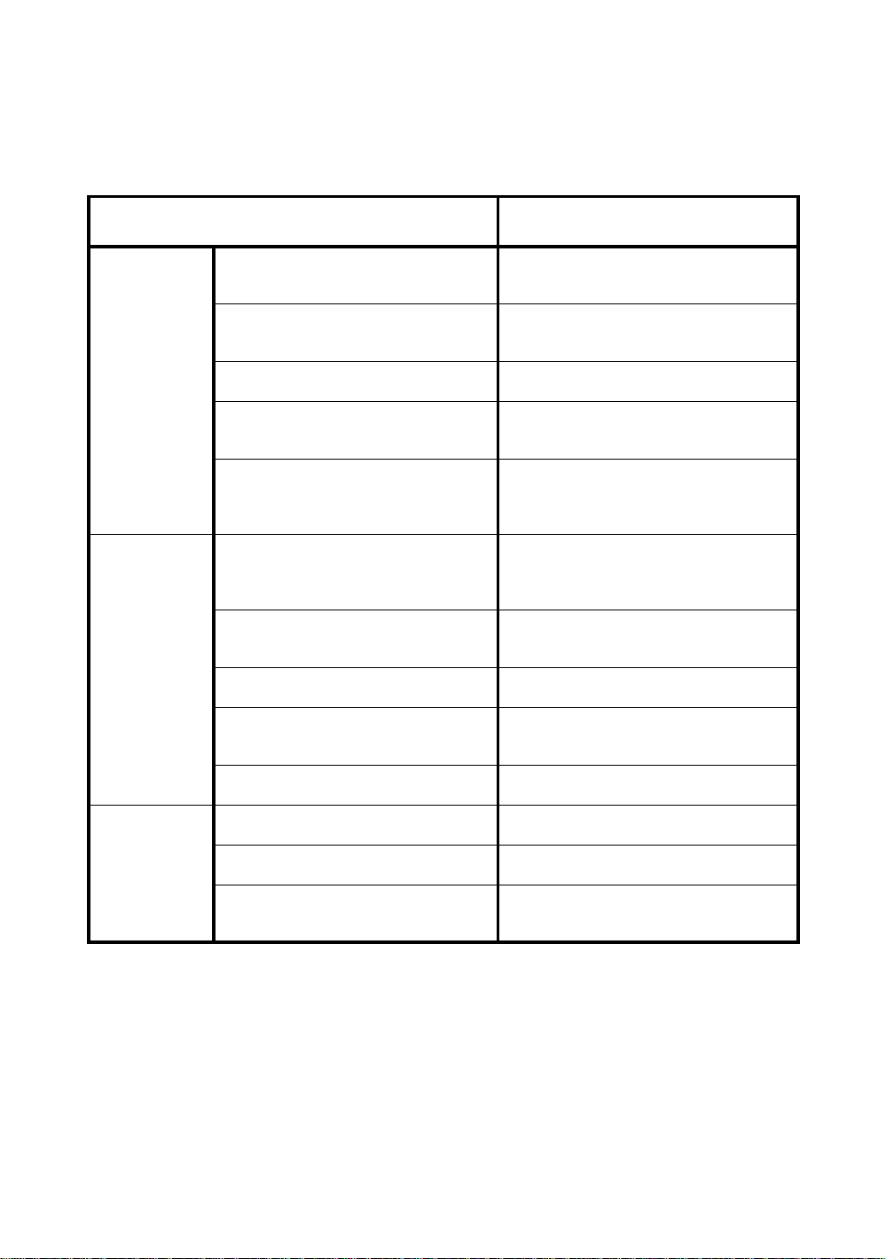
3.4.1 Setting Items
Items Selecting item Contents
SEARCH
PATTERN
SEARCH
RANGE
WAIT TI ME 0:00 to1:00:00
TRACKING
SPEED
REFLECTOR
TYPE
PREDICTION
CTRL TIME
PATTERN 1 The search range is the area to searche d fo r the pr ism by rotating
PATTERN 2
V:0° to 90°
H:0° to180°
(1sec. step)
HOLD
SURVEY Select your purpose.
MACHINE
CONTROL
PRISM The type of the reflector can be selected.
REFLECTOR
TAPE
0.5sec./ 1sec. /
2sec. /3sec. / 4sec
/ 5sec.
the telesc ope and body in sea rching.
The search range is the area to searche d fo r the pr ism by rotating
the telesc ope and body in sea r ching. The SEARC H range is
decided from the point where the prism lost, and the values will be
set to plus and mi nus di re ct ions in horizon tal and vertical. Al s o it is
enable to set each search pattern separately.
The time the prism is lost be for e GTS-820A series starts the
searching. If the mode is set to [HOLD], mode will not change to
searching.
After the instrument loses a prism, the time (prediction operation
time) for the instrument to continue moving operation can be set up.
1) Search Patterns
The search p att e rn i s the rotating method of teles cope and instru men t to f i nd the t arg e t prism in s ea rc h
mode. Search pattern includes the following 2 ways that can be selected.
This patter n can be selected to search the pr ism at the point where the prism is lost.
Instrument searches in up down direction gradually from the point whe re the prism is los t.
PATTERN 1
PATTERN 2
1) Things like hea t haze m ight interfer e w it h th e t r acking syste m in the long di s t anc e, near li mi t of auto
2) Reaction by rotating of inst r ume nt in search mode is se rious. Be sure of each connect io n part of the
The searching is arranged to 2 times until the prism is found.
The au t o tr acking mode changes to manual mode w hen the refl ec tor co ul d not found out
within 2 times searching, and returns to the point where the reflector is lost.
This patt ern can be selected to search for the prism. The search patt er n tri es to locate the
prism in a very short time.
The searching is arranged to 2 times until the reflector is found.
The au t o tr acking mode changes to manual mode w hen the refl ec tor co ul d not found out
within 2 times searching, and returns to the point where the reflector is lost.
tracking range, in search mode.
tribrach or tri pod are firmly.
2) Search Range
The search range is the area to searched for the prism by rotating the telescope and body in Searching.
The Search ran ge is decided fr om the point wher e the prism lost, and the values will be set to plus an d
minus directions in horizontal and vertical.
Select search pattern f ir st, and set the sea r ch r ange to the selected sear ch pattern . Als o it is enabl e to
set each search pattern separately.
3-5
Page 41

3 AUTOMATIC TR ACKING / AUT OMATIC COLLIMATION
[Examp le] SEARC H RANG E : 10° in horizontal, 5° in vertical
Search range
+5°
10°
Point where prism lost
-10° +10°
20°
Setting Sea rch ra nge requi res considera ti on . The items to think about: opti ca l path interrupted by other
objects; collimated point from GTS-820A series to prism is shifted a fter Turning and Searching
Command; possible other prisms, targets, or other objects to interfere with tracking the desired prism;
and many other examples all pl ay a ro le in determining the sear ch range.
Note: This search r ang e is onl y for auto-tracking fu ncti o n. The s earc h range of auto-collimating is f ixed
as ±5° in both directions horizontal and vertical.
-5°
3) Wait Time
The time the prism is lost before GTS-820A series starts the searching. Setting time is 1second step
maximum 60 minutes.
If the mode is set to [HOLD], mode will not change to searching.
4) Tracking Speed
Choose the mode of “Survey” or “Machine Control” according to the purpose of measurement.
l In case requiring auto aiming in high accuracy to the prism which is still.
SURVEY
MACHINE
CONTROL
Note: If the Machine Control mode i s chosen, the GTS-820A may incorrect-track the headlight of a car
etc. temporarily.
l Suitable for fixed point observation, management of landslides, surveying
displacement of dam.
l When beginning auto-tracking, the instrument needs to collimate stable prism.
l Suitable for controlling of construction machinery or real time surveying of variety
traveling objects.
l When beginning auto-tracking, the instrument can track a prism, even if the prism is
moving.
5) Refl ector type
You can choose a reflector type according to reflective objects such as Prism-2 or reflector tape.
This setting will reduce incorrect tracking.
6) Prediction operating time
After the instrument loses a prism, the time (prediction operation time) for the instrument to continue
moving operation can be set up.
During auto t r acking ope r ation, when auto tr acking axis b etwee n the i nstrument and a prism is
intercepted by a tree etc., the moving is continued supposing a motion (prediction) of the prism till then.
It is effect iv e in auto tracking op eration after t he prism is intercepted wi th the obstac l e by thi s fun ct ion.
When an obstacle is large, the prediction operation time should be set up long.
Moreover, when you want to terminate auto tracking operation immediately at the point which missed
the prism, and to be changed into a search state. Prediction operation time should be set up short.
3-6
Page 42

3 AUTOMATIC TR ACKING / AUT OMATIC COLLIMATION
3.4.2 How to set the parameters
Sample setting: Set TRACKING SPEED to [MACHINE CONTROL]
Operating procedure Option Display
1
Press the star [*] key to be in star key mode.
[
]
*
2003-10-10 14:30:40
1
↓
2
Press the [F3] key to select the setting
parameters for auto-tracking.
3
Press the [F6] (P↓) key to get the menu on
page 2.
4
Press the [F1](TRK SPEED) key.
5
Press the [F6] (↓) key to select [MACHINE
CONTROL].
6
Press the [ENT] key to de ci de .
[F3]
[F6]
[F1]
[F6]
[ENT]
F1:SEARCH PATTERN
F2:SEARCH RANGE
F3:WAIT TIME
P↓
F1:TRK SPEED
F2:REFLECTOR TYPE
F3:PREDICTION CTRL TIME
P↓
TRACKING SPEED
SURVEY
↑ ↓
TRACKING SPEED
MACHINE CONTROL
↑ ↓
3-7
Page 43

4 STANDARD MEASUREMENT MODE
)
4 STANDARD MEASUREMENT MODE
2003-10-10 15:30:40
Prog
Std
Mem Comm
Adj
Para
4.1 Angle Measurement
4.1.1 Measuring Horizontal Angle Right and Vertical Angle
Make sure the mode is in Angle measurement.
Operating procedure Operation Dis play
1
Collimate the 1st target (A).
[Press [F2] key .]
STANDARD MEASUREMENT MODE
Angle mea surement, Distance measurement,
Coordinate measurement .
Collimate
A
V : 87°55'45"
HR: 180°44'12"
SD HD NEZ 0SET HOLD P1
2
Set horizontal angle of target A at 0° 00' 00".
Press [F4]( 0 set) key and [F6](SET) key.
3
Collimate the 2nd target (B).
The required H/V angle to target B will be
displayed.
[F4]
[F6]
Collimate
B
H-0SET
HR: 00°00'00"
ESC SET
V : 87°55'45"
HR: 00°00'00"
SD HD NEZ 0SET HOLD P1
V : 87°55'45"
HR: 123°45'50"
SD HD NEZ 0SET HOLD P1
Reference : How to Collimate
1 Point the telescope toward the ligh t . Turn the diopter ring and adjust the diopter so that the cross
hairs are clearly observed.
(Turn the diopter ring toward you first and then bac k wa r d to focu s. )
2 Aim the target at the peak of the triangle mark of the sighting collimator. Allow a certain space
between the sighting collimator and yourself for collimating.
3 Fo cus t he target with the focusing knob.
↓
↓
↓
*If parallax is created between the cross
hairs and the targ et when viewin g
vertically or horizontally while looking
into the telescope, focusing is incorrect
or diopter adjustment is poor.
This advers el y affects precision in
measurement or survey. Eliminate the
parallax b y carefully focusing and usin g
diopter adjustment.
4-1
Åá
Åá
Focusing knob
T el escop e eyep iece ( Diop ter ring
Åá
Åá
Page 44

4 STANDARD MEASUREMENT MODE
4.1.2 Switching Horizontal Angle Right/Left
Make sure the mode is Angl e mea sur ement.
Operating procedure Operation Display
1
Press [F6](↓)key to get the f unc ti on as on
page 2.
[F6]
2
Press [F3](R/L ) key.
The mode Horizontal angle Right (HR)
switches to (HL) mode.
3
Mea sure as HR mode.
l Every time pressin g [F2]( R /L) key i s press ed, HR/HL mode swit ch es.
l HR/HL switching can be turned OFF. Refer to Chapter 8 “PARAMETERS SETTING MODE” .
[F3]
V : 87°55'45"
HR: 120°30'40"
SD HD NEZ 0SET HOLD P1
TURN HSET R/L V/% TILT P2
V : 87°55'45"
HL: 239°29'15" PSM 0.0
PPM 0.0
(m) *F.R
TURN HSET R/L V/% TILT P2
4.1.3 Measuring from the Required Horizontal Angle
1) Setting by Holding the Angle
Make sure the mode is angle measurement.
↓
↓
↓
Operating procedure Operation Dis play
1
Set the requ ired horizontal angle, using
Horizontal jog/shuttle.
2
Press [F5](HO LD) key.
3
Collimate the target.*1)
4
Press [F6](REL) key to finish holding the
horizontal angle.
The display turns back to normal angle
measurement mode.
*1)To return to the previous mode, press [F1](ESC) key.
Collimate
Display
angle
[F5]
[F6]
V : 90°10'20"
HR: 70°20'30"
SD HD NEZ 0SET HOLD
Holding
HR: 70°20'30"
ESC REL
V : 90°10'20"
HR: 70°20'30"
SD HD NEZ 0SET HOLD P1
P1
↓
↓
4-2
Page 45

2) Setting a Horizontal Angle from the Keys
Make sure the mode is Angl e mea sur ement.
Operating procedure Operation Display
1
Collimate the target.
2
Press [F6](↓) key to get the function as on
page 2, and press [F2](HSET) key.
3
Input the required horizontal angle.
*1)
For example:70
4
Press [ENT] key. *2)
°
20'30"
When complet e d, nor mal mea suring from th e
required Horizontal angle is possible.
Collimate
[F6]
[F2]
Input
value
[ENT]
4 STANDARD MEASUREMENT MODE
V : 90°10'20"
HR: 120°30'40"
SD HD NEZ 0SET HOLD P1
TURN HSET R/L V/% TILT P2
H-SET
HR:
H-SET
HR:70.203
EXIT BS
V : 90°10'20"
HR: 70°20'30"
SD HD NEZ 0SET HOLD P1
↓
↓
↓
*1)To revise wrong value, move curs or with [ F6](BS) key, or input from the be ginning by [F1](EXIT) key to
correct value.
*2)With wrong input value (for example 70'), setting will not be completed. Input again from step
3
.
4.1.4 Vertical Angle Percent Grade(% ) Mode
Make sure the mode is Angl e mea sur ement
Operating procedure Operation Dis play
1
Press [F6](↓) key to get the function as on
page 2.
2
Press [F4](V/%) key . *1)
*1) Every time pressing t he [F4](V/%) key, the display mo de switches.
.
V : 90°10'20"
HR: 120°30'40"
[F6]
[F4]
SD HD NEZ 0SET HOLD P1
TURN HSET R/L V/% TILT P2
V%: -0.30 %
HR: 120°30'40"
TURN HSET R/L V/% TILT P2
↓
↓
↓
4-3
Page 46

4 STANDARD MEASUREMENT MODE
4.1.5 Automatic Rotation to a Required Horizontal and Vertical Absolute Angle
The GTS-820A series can be rotated to a required horizontal and vertical absolute angle by direct key
input.
Example: Both vertical and horizontal angle
Operating procedure Operation Display
1
Press the [F6](↓) key to display the second
soft key page.
2
Press the [F1]( TURN) key.
3
Press the [F3] key.
4
Input the vertical angle to be rotated and
press [ENT] key. *1)
For example : 93
°
10'40"
[F6]
[F1]
[F3]
V angle
[ENT]
H angle
[ENT]
V : 87°55'45"
HR: 120°30'40"
SD HD NEZ 0SET HOLD P1
TURN HSET R/L V/% TILT P2
TURN(Absolute)
F1. V angle
F2. H angle
F3. V/H angle
TURN(Absolute
V :
HR:
EXIT
)
BS
↓
↓
5
Input the horizontal angle to be rotated, and
press [ENT] key.
For example : 160
The instrument will start to rotate. *2)
When the i nstrume nt h as fini shed rota ting *3) ,
the instrument will return to the previous
mode.
*1) Setting range for rotation is ;
0°00' 00"≤ HR ≤+359°59' 59"
0
°
00' 00"≤ V ≤ +359°59' 59"
*2) Press any key except pow er key to sto p rotati n g in em erge ncy during oper ation.
*3) You ca n select a ac curacy of the ac tual st opp ing angular positions. Refer to Chapter 8
“P AR AMETERS SE TTI N G MOD E” .
°
20'10"
TURN(Absolute
V : 93°10'10"
HR: 160°2 0' 10"
<
Rotating...
)
>
4-4
Page 47

4 STANDARD MEASUREMENT MODE
4.2 Distance Measur eme nt
4.2.1 Setting of the Atmospheric Correction
When setting the atmospheric correction, obtain the correction value by measuring the temperature
and pressure.
Setting the atmosp heric correct ion is in the STAR key (H) mode, see Chapter 11 “SETTING
A T MOSPHERI C CORRECTION” .
4.2.2 Setting of the Correction for Prism Constant
Topcon's prism constant value is 0. Set correction for prism at 0. If the prism is of another manufacture,
the appropriate co nst ant shall be set befor ehand.
Setting the prism constant value is in the STAR key (H) mode, see Chapter 10 “SETTING THE PRISM
CONSTANT VALUE” .
4.2.3 Di stance Measureme nt (Continuous Me asurement)
Make sure the mode displays angle measurement
Operating procedure Operation Display
1
Collimate the center of prism.
.
V : 90°10'20"
HR: 120°30'40"
SD HD NEZ 0SET HOLD P1
↓
2
Press [F1]( SD ) key or [F2]( HD )key.
*1), 2)
[Exa m ple] Horizontal distance mode
The result are shown *3) ~ *6)
The following characters will be shown on the 4th line right hand corner of the display to
*1)
[F2]
V : 90°10'20"
HR: 120°30'40" PSM 0.0
HD: < PPM 0.0
VD: (m) *F.R
MEAS MODE VH SD NEZ P1
V : 90°10'20"
HR: 120°30'40" PSM 0.0
HD: 716.661 PPM 0.0
VD: 4.001 (m) *F.R
MEAS MODE VH SD NEZ P1
represent measurement mode.
F: Fine meas. mode, C: Coarse (1mm) meas. mode, c: Coarse (10mm) meas. mode.
R: Continuous (Repeat) m eas . m ode , S: Single meas. mode, N: N time meas. mode
*2) When EDM is working , the "* " mark app ears in the display.
*3) The result is shown with buzzer sound.
*4) Measurement may repeat automaticall y if the result is affected by shimmer etc..
*5) To change sing le meas uri n g, pr ess [F1 ] (M EAS ) key.
*6) To return to the angle measur ement mode, press [F3](VH) key.
↓
↓
4-5
Page 48

4 STANDARD MEASUREMENT MODE
4.2.4 Distance Measurement (Single/N-times Measurement)
When presetting the number of times, the instrument measures the distance as the setting times and
the average distance will be displayed.
When presetting the number of times as 1, it does not display the average distance, because of single
measurement. It has been set at single measurement at factory.
1)Setting the number of times
Confirm the angle measurement mode.
Operating procedure Operation Dis play
1
Press [F1](SD) or [F2](HD) key.
V : 90°10'20"
HR: 120°30'40"
SD HD NEZ 0SET HOLD P1
↓
2
Press [F6](↓) key to get the f unction page as
2.
3
Press [F3](ME AN ) key.
4
Input the se tting t he number of t imes, and
press [ENT] key. *1)
[Example] 4 times
N-times measurement starts.
2)Measuring Method
Confirm the angle measurement mode.
Operating procedure Operation Dis play
1
Collimate the center of the prism.
2
Select the measurement mode by pr essing
[F1](SD) or [F2](HD) key.
Example: Horizontal distanc e
N-times measurement starts.
[F2]
[F6]
[F3]
[F4][ENT]
Collimate
[F2]
V : 90°10'20"
HR: 120°30'40" PSM 0.0
HD: PPM 0.0
VD: (m) F.R
MEAS MODE VH SD NEZ P1
REC SO MEAN m/ft P2
Average times
N:0
EXIT BS
V : 90°10'20"
HR: 120°30'40" PSM 0.0
HD: < PPM 0.0
VD: (m) *F.N
REC SO MEAN m/ft P2
V : 90°10'20"
HR: 120°30'40"
SD HD NEZ 0SET HOLD P1
V : 90°10'20"
HR: 120°30'40" PSM 0.0
HD: PPM 0.0
VD: (m) F.N
MEAS MODE VH SD NEZ P1
↓
↓
↓
↓
↓
4-6
Page 49

4 STANDARD MEASUREMENT MODE
V : 90°10'20"
HR: 120°30'40" PSM 0.0
HD: 54.321 PPM 0.0
VD: 1.234 (m) *F.N
MEAS MODE VH SD NEZ P1
The averag e val ue is disp laye d foll owing wi th
buzzer sound and “ * ” mark disappears.
V : 90°10'20"
HR: 120°30'40" PSM 0.0
HD: 54.321 PPM 0.0
VD: 1.234 (m) F.N
MEAS MODE VH SD NEZ
l Press [F1](MEAS) key for re-measuri ng aft er the mea sur e me nt in held.
l To return to the continuous measuring , press [F1](MEAS) key twice.
l To return to the angle measuring mode , press [F3](VH) key.
P1
↓
↓
4-7
Page 50

4 STANDARD MEASUREMENT MODE
4.2.5 Fine / Coarse Measuring Mode
•Fine mode : This is a normal distance measuring mode.
Measurement time 0.2mm mode: approx.2.8 seconds
The unit to be displayed is 0.2mm or 1m m. (0. 001ft or 0.005ft)
•Coarse mode : This mode measures in shorter time than in fine mode.
(1mm) Use this mode for the objects which may be slightly unstable.
Measurement time : approx. 0.7 seconds
The unit to be displayed is 1mm. (0.005ft)
•Coarse mode : This mode measures in shorter time than in coarse(1mm) mode.
(10mm) Use this mode for stake out measurement. It is very useful when tailing the
moving object or carrying out stake-out work.
Measurement time : approx. 0.4 seconds
The unit to be displayed is 10mm. (0.02ft)
Operating procedure Operation Dis play
1
Collimate the center of prism.
2
Select the measurement mode by pr essing
[F1](SD) or [F2](HD) key.
Example: Horizontal distanc e
Measuring starts.
1 mm mode : approx.1.2 seconds
Collimate
[F2]
V: 90°10'20"
HR: 120°30'40"
SD HD NEZ 0SET HOLD P1
V : 90°10'20"
HR: 120°30'40" PSM 0.0
HD: < PPM 0.0
VD: (m) *F.R
MEAS MODE VH SD NEZ P1
↓
↓
3
Press [F2](MODE) key, the mode changes to
Coarse mode.
Press [F2]( MODE ) key again, the mode
changes to Tracking mode. *1)
[F2]
[F2]
V : 90°10'20"
HR: 120°30'40" PSM 0.0
HD: PPM 0.0
VD: (m) c.R
MEAS MODE VH SD NEZ P1
*1) Every time the [F2](MODE) key is pressed, the mode will change as demonstrate d.
The mode is indicated in the alphabet (F, C, c) on the bottom right of the screen.
F: Fin e mode, C: Co arse 1mm mo d e, c: coa rse 10mm mode
↓
4-8
Page 51

4 STANDARD MEASUREMENT MODE
4.2.6 Stake Out (S-O)
The stake out distance is the dif fer ence between t he measured di stance and t he preset dista nce.
Display value = Measured distance -Standard (Preset) distance
The value on the display is the distance in which the rod person must move toward or away from the
instrume nt. A m inus (-) si gn appearing before the stake out distance indicates that the rod person
would move away from the instrument to reach the stake out distance. If the stake out distance is
displayed with no sign, indicating positive (+), the rod person toward the instrument to reach the stake
out distance.
l Stake out operation can be accomplished in any distance measuring mode, horizontal distance
(HD), relative elevation (VD), or slope distance (SD).
[Example: Relative ele vat ion]
Operating procedure Operation Dis play
1
Press [F6]( P1) key in the dis tanc e measur ing
mode to get the function as in page 2.
2
Press [F2]( S-O ) key and press [EN T] key.
3
Enter the r e l ative elevation for stake out, and
press [ENT] key.
The measuring starts.
4
Collimate the target (Prism).
[F6]
[F2]
[ENT]
Enter
value
[ENT]
V : 90°10'20"
HR: 120°30'40" PSM 0.0
HD: PPM 0.0
VD: (m) F.R
MEAS MODE VH SD NEZ P1
TU R N S O M E A N m/f t P 2↓
SO
HD : 0.000
VD :
EXIT BS
V : 90°10'20"
HR : 120°30'40" PSM 0.0
HD : < PPM 0.0
dVD : (m) *F.R
TURN SO MEAN m/ft P2
↓
↓
The difference between the measured
distance and the standard distance is
displayed.
V : 90°10'20"
HR: 120°30'40" PSM 0.0
HD: 12.345 PPM 0.0
dVD: 0.09 (m) *F.R
TURN SO MEAN m/ft P2
↓
l To return to normal distance measurement mode, reset the standard distance to “ 0 ” or turn the power
switch off (Resume mo de: OFF ) once.
4-9
Page 52

4 STANDARD MEASUREMENT MODE
E
4.3 COORDINATE MEASUREMENT
4.3.1 Setting Coordinate Values of Occupied Point
The occupie d point coordinates (NEZ) ca n be pr e set in th e GTS -820A Series to calcul ate the unknown
point coordinates. It is possible to retain the occupied coordinates in memory once the power is turned
OFF if the (NEZ mem) is ON in the Parameter Setting Modes. IF (NEZ mem) is OFF in the Parameter
Setting Modes, the occupied coordinates will be retained only if you choose (Resume ON) when
shutting the power OFF.
For instructions on how to select NEZ memory ON/OFF, refer to Chapter 8 “PARAMETERS SETTING
MODE” .
N
Prism (n,e,z)
z
n
Inst.PointC
Origin(0,0,0)
e
Confirm the angle measurement mode.
Operating procedure Operation Dis play
1
Press [F3](NEZ) key.
2
press [F6](↓) key to get the function as on
page 2.
3
Press [F5](SET) key.
The previous data will be shown.
[F3]
[F6]
[F5]
V : 90°10'20"
HR: 120°30'40"
SD HD NEZ 0SET HOLD P1
N : <
E : PSM 0.0
Z : PPM 0.0
(m) *F.R
MEAS MODE VH SD HD P1
TURN HT MEAN m/ft SET P2
Setting occ. point
N : 12345.6700
E : 12.3400
Z : 10.2300
EXIT BS
↓
↓
↓
4-10
Page 53

4
Input new data and press [ENT] key. *1)
Measuring starts.
*1)To cancel the setting, press [F1](EXIT) key.
N coord.
[ENT]
E coord.
[ENT]
Z coord.
[ENT]
4 STANDARD MEASUREMENT MODE
Setting occ. point
N : 0.0000
E : 0.0000
Z : 0.0000
EXIT BS
Complete
N : <
E : PSM 0.0
Z : PPM 0.0
(m) *F.R
TURN HT MEAN m/ft SET P2
↓
4-11
Page 54

4 STANDARD MEASUREMENT MODE
4.3.2 Setting of the Instrument Height / Prism Height
The instrument height and prism height are used to compute the ground elevation of the unknown
point. If the option to store NEZ i s (on), the instrument and pris m heights will be st ored in memory when
power is turned off.
Confirm the angle measurement mode.
Operating procedure Operation Dis play
V : 90°10'20"
HR: 120°30'40"
SD HD NEZ 0SET HOLD P1
1
Press [F3](NEZ) key.
2
Press [F6](↓) key fr om the coordi nate
measurement mode to ge t the f unction as in
page 2.
3
Press [F2] (HT) key to type in t he i nstrument
and prism height.
Previous data will be shown.
4
Input instrument height, and press [ENT]
key.*1)
[F3]
[F6]
[F2]
Inst. HT
[ENT]
N :
E : PSM 0.0
Z : PPM 0.0
(m) *F.R
MEAS MODE VH SD HD P1
TURN HT MEAN m/ft SET P2↓
Inst. Ht : 1.230 m
R. Ht : 1.340 m
EXIT BS
↓
↓
5
Input prism height, and press [ENT] key.
The display returns to coordinate measuring
mode.
*1)To cancel the setting, press [F1](EXIT) key.
Prism HT
[ENT]
N :
E : PSM 0.0
Z : PPM 0.0
(m) *F.R
TURN
HT MEAN m/ft SET P2
↓
4-12
Page 55

4 STANDARD MEASUREMENT MODE
4.3.3 Execution of Coordinate Measuring
Measure the coordinates by entering the instrument height and prism height, coordinates of unknown
point will be measured directly.
l When setting coordinate values of occupied point, se e Section 4.3.1“Setting Coordinate Values of
Occupied Point” .
l When setting the instrument height and prism height, see Section 4.3.2“Setting of the Instrument
Height / Pri sm Hei ght” .
l The coordinates of the unknown point are calculated as shown below and displayed:
Coordinates of the center of the prism, originated from the center point of the instrument (n,e,z)
Coordinates of occupied point : (N
, E0, Z0)
0
Instrument height : Inst.h
Prism height : R.h
Vertical distance (Relative elevation) : z
Coordinates of the center of the prism,
originat ed from the center point of the inst rument : (n,e,z)
Coordinates of unknown point : (N
N
= N0 + n
1
E
= E0 + e
1
Z
= Z0 + Inst.h + z - P.h
1
, E1, Z1)
1
Center point of the instrument
(No, Eo, Zo + Inst.h)
Occupied point (No, Eo, Zo)
Origin (o, o, o)
Confirm the angle measurement mode.
Operating procedure Operation Dis play
1
Set coordinat es values of occupied point and
instrument/prism height. *1)
2
Set the direction angle of known point A. *2)
3
Collimate target B.
4
Press [F3](NEZ) key.*3)
Measuring starts.
Unknown poin t
(N
1
, E1, Z1)
Set
direction
angle
Collimate
[F3]
V : 90°10'20"
HR: 120°30'40"
SD HD NEZ 0SET HOLD P1
N :
E : PSM 0.0
Z : PPM 0.0
(m) *F.R
MEAS MODE VH SD HD P1
<
↓
↓
4-13
Page 56

4 STANDARD MEASUREMENT MODE
The result will be shown.
N : 12345.6789
E : -12345.6789 PSM 0.0
Z : 10.1234 PPM 0.0
(m) *F.R
MEAS MODE VH SD HD P1
↓
*1) In case the coordinate of instrument point is not entered, (0,0,0) will be used as the default for the
instrument point.
The instrument height will be calculated as 0 when the instrument height is not entered.
*2) The prism h eigh t will be calculated as 0 when the prism height is not set.
*3) Refer to Section 4.1.3“Measuring from the Required Horizontal Angle”or Section 4.1.3“Measuring from
the Required Horizont al Angl e ”
*4) Pressing [F1](MEAS) key, the measurement mode (Continuous measuring/ N-time measuring)
changes.
Pressing [F2](MODE) key, the measurement mode ( F IN E / COARS E (1mm)/ C OARSE(10mm))
changes.
l To return to th e nor m al angl e or distance measuring mode, press [F6](P2
↓
) key to return to the function
as on page 1 and press [F3](VH),[F4](SD) or [F5](HD) key.
4-14
Page 57

4 STANDARD MEASUREMENT MODE
4.4 DATA OUTPUT
Result of meas ur e men t is tran sf er r ed to Data Collector (FC serie s) from GT S-8 20A serie s.
[Example: Di s tance measurement mo de]
Confirm the distance measurement mode.
Operating procedure Displ ay
1
Operate the data collector to measure the distance.
Measurement will be start ed.
2
The result will be shown and transferred to the Data
Collector.
3
The mode will automatically return t o t he di stance
measurement mode.
V : 90°10'20"
HR: 120°30'40" PSM 0.0
HD: < PPM 0.0
VD: (m) *F.R
MEAS MODE VH SD NEZ
V : 90°10'20"
HR: 120°30'40" PSM 0.0
HD: 10.1234 PPM 0.0
VD: 1.234 (m) *F.R
REC > > >
V : 90°10'20"
HR: 120°30'40" PSM 0.0
HD: 10.1234 PPM 0.0
VD: 1.234 (m) *F.R
MEAS MODE VH SD NEZ P1
P1
↓
↓
The following data will be output at each mode.
Mode Output
Angle mode (V,HR or HL) (V in percent) V, HR (or HL)
Horizontal distance mode (V, HR, HD, VD) V, HR, HD, VD
Slope distance mode (V, HR,SD) V, HR, SD,HD
Coordinate mode N, E, Z, HR
l The disp lay and the outp ut at the coarse (1mm) mode are the same as the con tents above.
l Output at the coarse (10mm) mode is displayed as distance data only (HD, VD o r SD).
The information of GTS-820A series regarding tracking auto-tracking are added to the protocol of
Topcon Total Statio n system so far.
Also you can add utility information such as bat tery rem aining, EDM mode, auto-trackin g mode, nor mal/
reversed face information, Tilt information if you like. For selecting, refer to Chapter 8 “PARAMETERS
SETTING MO DE” .
During an utilit y functio n selec t ion, measurement will be continued whenever tilt over. Th e tilt over will
not be compensated here.
In case tilt over, the tilt information will be displayed on the upper right screen as the following marks
during the uti l ity functio n is selected.
V : 90° 10'20" [t]
HR: 120° 30'40" PSM 0.0
HD: < PPM 0.0
VD: (m) *c.R
MEAS MODE VH SD NEZ P1
↓
Tilt information
Marks Status of tilt
[t] Under tilt compensation
[?] Tilt Over
[*]
Tilt OFF
4-15
Page 58

4 STANDARD MEASUREMENT MODE
l Control by interface for Topcon AP-L1A system, see Chapter 5 “PROGRAM MODES” -[EXT.LINK]
section.
l When using other wireless modem or optical remote controller, select to [None] for the protocol of
communication in Chapter 8 “PARAMETERS SETTING MODE” .
4-16
Page 59

5 PROGRAM MODES
5 PROGRAM MODES
2003-10-10 15:30:40
Prog
l The loaded measuring programs are added on this menu.
Programs
F1 BS p 4/7
F2 STORE p
F3 REM p
F4 MLM p MORE
Mem Comm
Std
PROGRAM MODE (APPLICATION MEASUREMENT)
1.Sett i ng a Horizontal Angle
2.Retaining a Coordinate (STORE-NEZ)
3.Remote Elevation Measurement (REM)
4.Missing Line Measur em ent (MLM)
5.Line Measurement (LINE)
6.Offset Measurements (OFF SET)
6.Ex ternal Link
Adj
Para
[F6](MORE) key
[Press [F1] key.]
Programs
F1 LINE
F2 OFFSET p
F3 EXT.LINK p
MORE
p 7/7
5-1
Page 60

5 PROGRAM MODES
5.1 Setting a Direction Angle for Backsight Orientation
(Ent erin g t h e in s trum e nt an d b acksight coordinate values)
From the coordinate value of backsight point (bearing point) and instrument point, the direction angle
from the instrument point to the backsight point can be set.
N
Backsight point A
Instrument point C
Direction angle
E
Example: Backsight point A : N coordinate 54.321m, E coordinate 12.345m
Operating procedure Operation Display
Programs
F1 BS p 4/7
F2 STORE p
F3 REM p
F4 MLM p MORE
1
Press [F1]( BS) key.
Current data will be displayed. *1)
2
Press [F6](OK ) key.
3
Input N and E coordinate of backsight point A.
Example : N coordinate;54.321m
: E coordinate;12.345m
4
Sight backsight point A.
5
Press [F5]( YES ) key.
The display returns to main menu.
*1)If you need to change the occupied point data, press [F1](INP) key and input new data.
[F1]
[F6]
N data
[ENT]
E data
[ENT]
[F5]
Setting Direction Angle
BS:M-POINT
N : 123 4. 56 7 m
E : 234 5 . 6 7 8 m
INP
Setting Direction Angle
BS:T-POINT
N : 54 .3 21 m
E : 12. 3 4 5 m
EXIT
Setting Direction Angle
BS
HR : 320°10'20"
>
Set OK
EXIT
Complete
BS
?
YES NO
OK
5-2
Page 61

5 PROGRAM MODES
5.2 Retaining a Coordinate (STORE- NEZ)
Suppose the instrument P0 moves to P1, P2, P3, etc. and the coordinate at P1, P2, P3 etc., last point
will be retained in the memory, after moving, as from th e origin point.
N
Known point A
Direction angle
Origin (0,0,0)
l Set the coordinate value of instrument point P
toward known point A
Operating procedure Operation Display
1
Press [F2](ST O RE) key.
2
Press [F1](Store NEZ) key. *1)
.
P
1
P
2
Inst. point P
0
and set the direction angle from instrument point P0
[F2]
[F1]
0
Programs
F1 BS p 4/7
F2 STORE p
F3 REM p
F4 MLM p MORE
Retaining Coordinate
1.Store NEZ
2.Recall NEZ
Store NEZ
HR : 120°30'40"
HD : m
P
3
E
3
Collimate target P1 prism which the
instrument mo ves.
4
Press [F1]( ME AS) key.
Measuring will start.
Horizontal distance and horizontal angle are
shown.
Collimate
P1
[F1]
5-3
MEAS HT SET
Store NEZ
HR : 100°10'20"
HD *
MEAS SET
Store NEZ
HR : 100°10'20"
HD * 123.456 m
MEAS
<
m
SET
Page 62

5
Press [F6]( SET ) key.
Coordinate of P1 will be displayed.
6
Press [F5]( YES ) key.
Coordinate of P1 will be decided.
[F6]
[F5]
5 PROGRAM MODES
Store NEZ
N : 123.456 m
E : 12.345 m
Z : 1.234 m
>
SET OK? YES NO
Complete
The display return to main menu.
Turn pow er off and move instr u me nt to P1
( Prism P1 move to P0).
7
After the instrument is set up at P1, turn
power on and be measurement possible.
8
Press [F2](ST O RE) key.
9
Press [F2]( Rec all NEZ ) key.
10
Collimate P0, the former instrument point.
11
Press [F5]( YES ) key.
Power off
Move to
P1
Power on
Select
program
[F2]
[F2]
Collimate
0
P
[F5]
Programs
F1 B S p 4 /7
F2 STORE p
F3 REM p
F4 MLM p MORE
Retaining a Coordinate
1.Store NEZ
2.Recall NEZ
Recall NEZ
HR: 300°10'20"
>
Set OK?
YES NO
Complete
The coordinates at P1 and direction angle
toward P
The display return to main menu.
12
Repeat the procedure 1 ~11 as much as you
wish.
*1)To reset the instrument height or prism height, press [F5](HT) key.
0
are set.
5-4
Page 63

5 PROGRAM MODES
5.3 Remote Elevation meas ur em ent (RE M)
To obtain elevation of the point at which setting the target prism is not possible, place the prism at any
point on the vertical line from the target then carry out REM procedure as follows.
Target K
Instrument
1) With prism height (h) input (Example :h=1.5m)
Operating procedure Operation Display
1
Press [F3](RE M) key.
2
Press [F1]( YES ) key.
Prism P
[F3]
[F1]
VD
Prism heig ht
G
Programs
F1 BS p 4/7
F2 STORE p
F3 REM p
F4 MLM p MORE
REM
Prism height
1.YES
2.NO
REM
(1)Prism Height
P.h : m
EXIT BS
3
Enter prism height, press [ENT] key.
4
Collimate prism .
5
Press [F1]( ME AS) key.
Measuring starts.
Enter
P.HT
[ENT]
Collimate
P
[F1]
5-5
REM
(2)Horizontal Distance
HD : m
MEAS SET
REM
(2)Horizontal Distance
HD * < m
MEAS SET
Page 64

5 PROGRAM MODES
Horizontal distance (HD) between the
instrument and prism will be shown.
6
Press [F6]( SET ) key.
The prism position will be decided. *1)
7
Collimate target K.
Vertical distance (VD) will be shown. *2)
*1)T o return to procedure
To return to procedure
*2)T o return to main menu, press [F1](EXIT) key.
3
, press [F2](P.h) key.
4
, press [F3](HD) key.
2)Without prism height input.
Operating procedure Operation Display
[F6]
Collimate
K
REM
(2)Horizontal Distance
HD : 123.456 m
MEAS SET
REM
VD : 0.234 m
EXIT P.h HD
REM
VD : 1.456 m
EXIT P.h HD
Programs
F1 BS p 4/7
F2 STORE p
F3 REM p
F4 MLM p MORE
SET
1
Press [F3](RE M) key.
2
Press [F2](NO ) key.
3
Collimate prism.
4
Press [F1]( ME AS) key.
Measuring starts.
Horizontal distance (HD) between the
instrument and prism will be shown.
[F3]
[F2]
Collimate
P
[F1]
REM
Prism height
1.YES
2.NO
REM
(1)Horizontal Distance
HD : m
MEAS
REM
(1)Horizontal Distance
HD* < m
MEAS SET
REM
(1)
Horizontal Distance
HD : 123.456 m
MEAS
SET
5-6
Page 65

5
Press [F6]( SET ) key.
The prism position will be decided.
6
Collimate ground point G.
7
Press [F6]( SET ) key.
The position of point G will be decided. *1)
8
Collimate target K.
Vertical distance (VD) will be shown. *2)
3
*1)T o return to procedure
To return to procedure
*2)T o return to main menu, press [F1](EXIT) AND [F5](YES) key.
, press [F2](HD) key.
6
, press [F3](V) key.
[F6]
Collimate
G
[F6]
Collimate
K
5 PROGRAM MODES
REM
(2)Vertical Angle
V : 120°30'40"
SET
REM
(2)Vertical Angle
V : 95°30'40"
SET
REM
VD : 0.000 m
EXIT HD V
REM
VD : 9.876 m
EXIT HD V
5-7
Page 66

5 PROGRAM MODES
5.4 Missing Lin e Measurement (M L M)
Measurement for horizontal distance (dHD), slope distance (dSD) and elevation (dVD) between two
target prisms.
MLM mode has two mods.
1.(A-B, A-C):Measurement is A-B, A-C, A-D,.............
2.(A-B, B-C):Measurement is A-B, B-C, C-D,.............
Prism A
Prism B
Instrument
[Example] 1. (A-B, A-C)
l Procedure of 2. (A-B, B-C) mode is completely same as MLM-1 mode.
Operating procedure Operation Display
1
Press [F4](ML M) key.
2
Press [F1](A-B, A-C) key.
[F4]
[F1]
Prism C
Programs
F1 BS p 4/7
F2 STORE p
F3 REM p
F4 MLM p MORE
Missing Line Measurement
1.(A-B, A-C)
2.(A-B, B-C)
MLM 1
Horizontal Distance 1
HD : m
MEAS SET
5-8
Page 67

3
Collimate prism A, and press [F1](MEAS) key.
Horizontal distance (HD) between the
instrument and prism A will be sho wn.
4
Press [F6]( SET ) key.
5
Collimate prism B and press [F1](MEAS) key.
Horizontal distance (HD) between the
instrument and prism B will be sho wn.
Collimate
A
[F1]
[F6]
Collimate
B
[F1]
5 PROGRAM MODES
MLM 1
Horizontal Distance 1
HD * < m
MEAS SET
MLM 1
Horizontal Distance 1
HD : 123.456 m
MEAS SET
MLM 1
Horizontal Distance 2
HD : m
MEAS SET
MLM 1
Horizontal Distance 2
HD * < m
MEAS SET
6
Press [F6]( SET ) key.
The horizontal distance (dHD) relative
elevation (dVD) and slope distance between
prism A and B.
7
To measure the distance between points A
and C, press [F2](HD) key. *1)
8
Collimate point C (Prism C) and press
[F1](MEAS) key.
Horizontal distance (HD) between the
instrument and prism C will be shown.
[F6]
[F2]
Collimate
C
[F1]
MLM 1
Horizontal Distance 2
HD * 246.912 m
MEAS SET
MLM 1
dHD : 123.456 m
dVD : 12.345 m
dSD : 12.456 m
EXIT HD
MLM 1
Horizontal Distance 2
HD : m
MEAS SET
MLM 1
Horizontal Distance 2
HD : < m
MEAS SET
5-9
Page 68

9
Press [F6]( SE T) key.
The horizontal distance (dHD) relative
elevation (dVD) and slope distance between
prism A and C.
10
To measure the distance between points A
and D, repeat procedure
*1)To return to main menu, press[ F1 ]( EX IT) and [F5](YES) key.
7
to 9. *1)
[F6]
5 PROGRAM MODES
MLM 1
Horizontal Distance 2
HD * 246.912 m
MEAS SET
MLM 1
dHD : 123.456 m
dVD : 12.345 m
dSD : 12.456 m
EXIT HD
5-10
Page 69

5.5 Line Measurement (LINE)
This mode is useful to obtain the line height.
5 PROGRAM MODES
L
P.h
Prism A
[Example:Input of prism height]
Operating procedure Operation Display
1
Press [F6]( MO RE) key fro m programs menu
to get the next page of programs.
Off
VD
HD
[F6]
LH
G
Prism B
Instrument
Programs
F1 BS p 4/7
F2 STORE
F3 REM p
F4 MLM
Programs
F1 LINE
F2 OFFSET p
F3 EXT.LINK p
MORE
p
p 7/7
p MORE
2
Press [F1](LINE) key.
3
Press [F1]( YES ) key.
4
Input the prism height and press [ENT] key.
Input P.h
5-11
[F1]
[F1]
[ENT]
LINE
Prism height
1 YES
2 NO
LINE
Prism height
P.h: m
EXIT BS
LINE
<STEP-1>PT A
HD: m
MEAS SET
Page 70

5
Collimate prism A and press [F1](MEAS) key.
The distance measurement will start.
Collimate
A
[F1]
5 PROGRAM MODES
LINE
<STEP-1>P
T A
HD* < m
Horizontal distance is displayed.
6
Press [F6] (SET) key, and hori zo ntal distance
will be recorded.
7
Collimate prism B and press [F1](MEAS) key.
The distance measurement will start.
Horizontal distance is displayed.
[F6]
Collimate
B
[F1]
LINE
<STEP-1>PT A
HD* 50.234 m
MEAS SET
LINE
<STEP-1>PT B
HD: m
MEAS SET
LINE
<STEP-1>PT B
HD* < m
MEAS SET
LINE
<STEP-1>PT B
HD* 67.543 m
MEAS SET
8
Press [F6] (SET) key, and hori zo ntal distance
will be recorded.
9
Sight line point L .
Measured data to the line point L is displayed.
VD:Vertical distance.
HD:Horizo ntal dist an ce fr om the ins tr ument to
L.
Off :Horizontal distance from A to L.
10
Press [F2](LH) key.
This f unction is used when meas ur i ng the l i ne
height from the ground. The pr ocedure is a s
follows :
l Sight the point on the line before pressing this
key.
l Don‘t move the horizontal tang ent scre w by
setting ground point G.
Sight L
5-12
[F6]
[F2]
LINE
VD: 20.123 m
HD: 38.987 m
Off: 74.123 m
EXIT LH
LINE
G-POINT
V : 30°20'10"
EXIT SET
Page 71

5 PROGRAM MODES
11
Rotate the vertical tangent screw, and sight
ground point G.
12
Press [F6] (SET) key, line height (LH) and
horizontal distance (Off ) are displayed.
l To finish the measurement, press the [F1](EXIT) or [ESC] key.
l To return to operation procedure 9 , press the [F2](VD) key.
l To return to operation procedure 11 , press the [F6](NEXT) key.
The N E XT key is used when the ground po i n t G is not clear and you would like to check another
ground point G on the same vertical line.
Sight G
[F6]
LINE
G-POINT
V : 90°40'20"
EXIT SET
LINE
LH: 33.765 m
Off: 27.521 m
EXIT VD NEXT
5-13
Page 72

5 PROGRAM MODES
5.6 Offset measurement (OFFSET)
There are four offset measurement modes in the Offset Measurement.
l Angle offset
l Distance offset
l Plane offset
l Column offset
Offset Measurement Menu
Programs
F1 LINE
F2 OFFSET p
F3 EXT.LINK p
MOR E
OFFSET MEASUREMENT
1.ANGLE OFFSET
2.DIST. OFFSET
3.PLANE OFFSET
4.COLUMN OFFSET
l Outputting the Measurement Data
The results of offset measurement can be output to external device.
In offs et measurem ent mode, the [F4] soft key wh ich assigned (REC) will appear in measured result
display.
p 7 /7
[F2](OFFSET)
ANGLE OFFSET
HR: 87°55'45"
HD: 20.000 m
VD: 5.000 m
NEXT SD NEZ REC
[F4](REC)
ANGLE OFFSET
HR: 87°55'45"
HD: 20.000 m
VD: 5.000 m
> REC ? YES NO
[F5](YES)
ANGLE OFFSET
HR: 87°55'45"
HD: 20.000 m
VD: 5.000 m
<REC>
l Distance measurement mode of the offset measurement
Offset measurement will be done by N-time fine measurement mode.
5-14
Page 73

5 PROGRAM MODES
5.6.1 Angle Offset
This mode is useful when it is difficult to set up the prism directly, for example at the center of a tree.
Place the prism at t he sam e horiz on t a l di stance fr om th e inst rument as that of point A0 to measure.
To measure the coordinat es of the center positi on, operate the of f set measurement after setti ng t he
instrument height/prism height.
Prism height
Instrument height
When measuring coordinates of ground point A
:Set the inst rum ent heig ht /prism height.
When measuring coordinates of point A
Prism P
the instrument height only. (Set the prism height
to 0 ).
When sight i ng to A
, you can select one of two
0
ways. [HOLD] is to fix vertical angle to the prism
positi on e ven updo wn the telesc ope position , and
[FREE] is to gear vertical angle to the updown of
telescope movement. In case fol l owing the
vertical angle to the movement of telescope,
SD(Slope Distance) and VD(Vertical Distance)
will be changed according to the movement of
telescope.
Occ. Poin t
Operating procedure Operation Display
: Set
0
1
1
Press [F6]( MO RE) key fro m programs menu
to get to the next page of program s.
2
Press [F2]( OF FSE T) key.
3
Press [F1]( AN GLE OFFSET) key.
[F6]
[F2]
[F1]
Programs
F1 B S p 4 /7
F2 STORE p
F3 REM p
F4 MLM p MORE
Programs
F1 LINE
F2 OFFSET p
F3 EXT.LINK p
MORE
OFFSET MEASUREMENT
1.ANGLE OFFSET
2.DIST. OFFSET
3.PLANE OFFSET
4.COLUMN OFFSET
ANGLE OFFSET
p 7/7
1.FREE V-ANGLE
2.HOLD V-ANGLE
5-15
Page 74

4
Select the vertical angle [FREE] or [HOLD].
*1)
5
Collimate prism P, and press the [F1](MEAS)
key . *1 )
The horizontal distance from the instrument
to the prism will be measured.
6
Collimate point A0 using the hor izon tal m otion
clamp and hori zon t al ta nge nt scr ew.
[F1]or [F2 ]
Collimate
P
[F1]
Collimate
A
0
5 PROGRAM MODES
ANGLE OFFSET
HD: m
MEAS HT
ANGLE OFFSET
HD* < m
MEAS HT
ANGLE OFFSET
HR: 20°30'40"
HD: 20.000 m
VD: 0.000 m
NEXT SD NEZ REC
ANGLE OFFSET
HR: 30°00'00"
HD: 20.000 m
VD: 0.000 m
NEXT SD NEZ REC
7
T o sh ow the slope distance of poi nt A0, press
the [F2](SD) key.
8
T o sho w the coordi nates, press the [F3 ](NE Z)
key . *2)
*1) To set the prism height or instrument height, press the [F5](HT) key.
*2) To repeat angle offset measurement, press the [F1](NEXT) key. The display will return to step 5.
[F2]
[F3]
ANGLE OFFSET
V : 90°00'00"
HR: 30°00'00"
SD: 20.000 m
NEXT HD NEZ REC
ANGLE OFFSET
N : 17.321 m
E : 10.000 m
Z : 0.000 m
NEXT SD HD REC
5-16
Page 75

5 PROGRAM MODES
5.6.2 Di stance Offset Measurement
The measurement of a place apart fr om a pris m is possi ble by inputting of f set hor izo ntal distance of
front and back / right and left.
Forward HD
oHD sign
Instrument height
When measuri ng coor dinates of ground point A
When measuring coordinates of point A
Operating procedure Operation Display
A
0
A
1
Occ.Point
Prism height
Prism P
: Set the instrument height / prism height.
1
: Set the instrument height only.
0
(Set the prism height to 0 ).
RorL HD
1
Press [F6]( MO RE) key fro m programs menu
to get to the next page of program s.
2
Press [F2]( OF FSE T) key.
3
Press [F2](DIST. OFFSET) key.
Previous of fset value screen will appear.
dFR: Forward/Rear offset value
dRL: Right/Left offset value
[F6]
[F2]
[F2]
Programs
F1 B S p 4 /7
F2 STORE p
F3 REM p
F4 MLM p MORE
Programs
F1 LINE
F2 OFFSET p
F3 EXT.LINK p
MORE
OFFSET MEASUREMENT
1.ANGLE OFFSET
2.DIST. OFFSET
3.PLANE OFFSET
4.COLUMN OFFSET
DIST. OFFSET
OK INP
p 7/7
dFR : 0.000 m
dRL : 0.000 m
5-17
Page 76

4
If you reset the offset value, press the
[F6](INP) key and input the value. *1)
5
Collimate prism using the horizontal motion
clamp and hori zon t al ta nge nt scr ew.
Press the [F1]( ME AS) key. *2)
The offset measurement data will be shown.
6
T o sh ow the slope distance of poi nt A0, press
the [F2](SD) key.
[F6]
Collimate
P
[F1]
[F2]
5 PROGRAM MODES
DIST. OFFSET
dFR : 0.000 m
dRL : 0.000 m
EXIT BS
DIST. OFFSET
HD: m
MEAS HT
DIST. OFFSET
HR: 30°00'00"
HD: 20.000 m
VD: 0.000 m
NEXT SD NEZ REC
DIST. OFFSET
V : 90°00'00"
HR: 30°00'00"
SD: 20.000 m
NEXT HD NEZ REC
7
T o sho w the coordi nates, press the [F3 ](NE Z)
key . *3)
*1) T o skip the input, press the [F1](OK) key.
*2) To set the prism height or instrument height, press the [F5](HT) key.
*3) To repeat the offset measurement, press the [F1](NEXT) key. The display will return to step 5.
[F3]
DIST. OFFSET
N : 17.321 m
E : 10.000 m
Z : 0.000 m
NEXT SD HD REC
5-18
Page 77

5 PROGRAM MODES
5.6.3 P l ane Offset M easurement
Measuring will be taken for th e place w her e direct measuring can not be done, for example distance or
coordinate measuri ng for a edge of a plane.
Three random target points (P1, P2, P3) on a plane will be measured at first in the plane offset
measurement to determine the measured plane. Collimate the measuring target point (P0) then the
instrument calculates and displays coordin ate and distance value of cross point between collimation
axis and of the plane.
(Prism)
Edge
(Point wit h out prism)
P
(Prism)
3
P
P
2
P
(Prism)
Target heights of P1 to P3 is set to zero automatically.
Operating procedure Operation Display
1
Press [F6]( MO RE) key fro m programs menu
to get to the next page of program s.
2
Press [F2]( OF FSE T) key.
3
Press [F3]( PLA NE OFFSET) key.
Measurement screen of three points on a
plane will be shown.
[F6]
[F2]
[F3]
Programs
F1 B S p 4 /7
F2 STORE p
F3 REM p
F4 MLM p MORE
Programs
F1 LINE
F2 OFFSET p
F3 EXT.LINK p
MORE
OFFSET MEASUREMENT
1.ANGLE OFFSET
2.DIST. OFFSET
3.PLANE OFFSET
4.COLUMN OFFSET
PLANE OFFSET
N001#
MEAS HT
p 7/7
SD : m
5-19
Page 78

4
Collimate prism P1, and press the
[F1](MEAS) key.
Measuring will start.
After measuring, the second point
measurement screen will be shown.
5
Measure the second and third prism in the
same way. *1)
Collimate
P1
[F1]
Collimate
P2
[F1]
Collimate
P3
[F1]
5 PROGRAM MODES
PLANE OFFSET
N002#
SD : m
MEAS HT
PLANE OFFSET
N003#
SD : m
MEAS HT
The instrumen t cal culates and displays
coordinate and dis t ance value of cross point
between collimation axis and of the plane. *2)
6
Collimate point P0 on the plane using the
horizontal motion cl amp and horizonta l
tangent screw.
P0 data will be shown.
7
T o sh ow the slope distance of poi nt P0, press
the [F2](SD) key.
8
T o sho w the coordi nates, press the [F3 ](NE Z)
key . *3),4)
*1) In case the calculation of plane was not successful by the measured three points, error displays. Start
measuring over again from the first poi nt .
*2) Error will be displayed when collimated to the direction which does not cross with the determined
plane.
*3) The reflector height of the target point P0 is set to zero automatically.
*4) To repeat the offset measurement, press the [F1](NEXT) key. The display will return to step 4.
Collimate
P0
[F2]
[F3]
PLANE OFFSET
HR: 85°30'40"
HD: 54.321 m
VD: 10.000 m
NEXT SD NEZ REC
PLANE OFFSET
HR: 75°30'40"
HD: 54.600 m
VD: -0.487 m
NEXT SD NEZ REC
PLANE OFFSET
V : 90°30'30"
HR: 75°30'40"
SD: 54.602 m
NEXT HD NEZ REC
PLANE OFFSET
N : 17.321 m
E : 10.000 m
Z : 20.000 m
NEXT SD HD REC
5-20
Page 79

5 PROGRAM MODES
5.6.4 Column Offset Measurement
If it is pos si ble to measu re circumsc ri ption point (P1) of colum n directly, the distance to the c enter of the
column (P0), coo rdina te and dire ctio n angle can be calcula ted by measur ed circu mscr ipti on points (P 2)
and (P3).
The direction angle of the center of the column is 1/2 of total direction angle of circumscription points
(P2) and (P3).
Operating procedure Operation Display
1
Press [F6]( MO RE) key fro m programs menu
to get to the next page of program s.
2
Press [F2]( OF FSE T) key.
[F6]
[F2]
P
3
P
Programs
F1 B S p 4 /7
F2 STORE p
F3 REM p
F4 MLM p MORE
Programs
F1 LINE
F2 OFFSET p
F3 EXT.LINK p
MORE
OFFSET MEASUREMENT
1.ANGLE OFFSET
2.DIST. OFFSET
3.PLANE OFFSET
4.COLUMN OFFSET
p 7/7
2
P
P
Prism
3
Press [F4]( CO LUM N OFF SET ) key.
Measurement screen of the center of a
column will be shown.
4
Collimate the center of the column (P1) and
press the [F1](MEAS) key.
Measuring will start.
After the measurement, angle measuring
display of the left side (P2) will be shown.
Collimate
5-21
[F4]
P1
[F1]
COLUMN OFFSET
Center
HD : m
MEAS HT
COLUMN OFFSET
Left
HR : 9
SET
0°30'40"
Page 80

5
Collimate the left side of the column (P2) and
press the [F6](SET) key.
After the measurement, angle measuring
display of the right side (P3) will be shown.
6
Collimate the right side of the column (P3)
and press the [ F6] (SET) key.
After the measure ment, the dist anc e betwee n
the inst rument and center of the column (P0)
will be calculated and displayed.
7
T o s how the slop e dis tance of point P0, press
the [F2](SD) key.
8
T o sho w the coordi nates, press the [F3 ](NE Z)
key . *1)
Collimate
P2
[F6]
Collimate
P3
[F6]
[F2]
[F3]
5 PROGRAM MODES
COLUMN OFFSET
Right
HR : 95
SET
COLUMN OFFSET
HR: 90°30'40"
HD: 10.321 m
VD: 0.886 m
NEXT SD NEZ REC
COLUMN OFFSET
V : 85°30'30"
HR: 90°30'40"
SD: 10.999 m
NEXT HD NEZ REC
COLUMN OFFSET
N : 17.321 m
E : 10.962 m
Z : 0.886 m
NEXT SD HD REC
°30'40"
*1) To repeat the offset measurement, press the [F1](NEXT) key. The display will return to step 4.
5-22
Page 81

5 PROGRAM MODES
5.7 External Lin k
You can use compatible communication command of AP-L1A for GTS-820A series. In this process
carry out setting for remote co n trol sys tem RC-2II using toge ther.
5.7.1 Starting compatible communication progra m of AP-L1A
Operating procedure Operation Display
1
Press the [F6](MORE) key to get the next
page.
2
Press the [F3]( EXT.LINK) key.
The c ompati ble prog ram EX TERNAL LINK
will start.
[F6]
[F3]
Programs
F1 BS p 4/7
F2 STORE p
F3 REM p
F4 MLM p MORE
Programs
F1 LINE P 7/7
F2 OFF SET P
F3 EXT.LINK P
MORE
EXTERNAL LINK
1 Execute
2 Setting
5.7.2 Setting for the communication
Decide transmit course and parameters before executing communication.
(1)Setting communication course
Sele c t a c ommunicat ion course accord ing to the us ing optional device.
1) Cable : In case connecting personal computer or other than Topcon's designated wireless
2) RADIO MODEM : In case connecting Topcon's designated wireless modem.
3) RC :In case carrying out optical communication using with the remote controller system
modem to the RS-232C connector.
RC-2II.
Operating procedure Operation Display
Execute Section 5.7.1“Starting compatible
communicat i on progra m of AP-L1A ” to start
[EXT.LINK] of compatible communication
program of AP-L1.
1
Press the [F2]( Setting) key.
2
Press the [F1] key to select [CABLE/RADIO
MODEM/RC]
5-23
[F2]
[F1]
EXTERNAL LINK
1 Execute
2 Setting
Setting
1 CABLE/RADIO MODEM/RC
2 PARAMETER(CABLE)
3 PARAMETER(RC)
4 PARAMETER(RADIO MODEM)
CABLE/RADIO MODEM/RC
CABLE
SET
↓ EXIT
↑
Page 82

3
Select comm unicat ion cours e by pre ssing t he
[F3](↑) or [F4](↓) key.
(Sam ple set ting : RC)
[F3]
or
[F4]
5 PROGRAM MODES
CABLE/RADIO MODEM/RC
RC
4
Press the [F1]( SET ) key to dec i de.
l To cancel the setting, press the [F6](EXIT)key or the [ESC] key.
[F4]
SET
Setting
1 CABLE/RADIO MODEM/RC
2 PARAMETER(CABLE)
3 PARAMETER(RC)
4 PARAMETER(RADIO MODEM)
↓ EXIT
↑
(2)Setting Parameters of Cable (RS-232C)
In case connec ting Topcon's designated wirele ss mod em, sim pl y select communicati o n cours e as
"RADIO MODEM" it i s enough to do setting of parameter automati cally.
In case connec ting personal co mpute r or othe r than Topcon's designate d wireless mo dem, it is requir ed
to do parameters setting for RS-232C before using.
Parameters
1) SPEED (B aud rate)
Sets communicatio n speed
Set items: 1200, 2400, 4800, 9600bps
2) BIT FORMAT
Select the communication format.
Set items:
Bit length : 7 : D7, 8 : D8
Stop bit : 1 : S1, 2 : S2
Parity bit : NONE, ODD, EVEN
3) DELIMITER (Terminate)
Selecting CR (Carriage return), or LF (Line feed) will be added at the end of data.
Set items:
4) RTS (Control of signal line)
5) REC TYPE
Execute Section 5.7.1“Starting compatible
communicat i on progra m of AP-L1A ” to start
[EXT.LINK] of compatible communication
program of AP-L1.
1
Press the [F2]( Setting) key.
ETX, ETX+CR, ETX+CRLF
Select default output of signal line
Set items:
Hi : High level (Normal)
Low : Low level (It becomes High leve l on ly when dat a are tra nsmitted.)
Select the option to record the data for the distance measurement.
REC-A : Measure the distance again and record the updated distance.
REC-B : Record the data for the last distance me asu r em ent on the display.
Operating procedure Operation Display
[F2]
EXTERNAL LINK
1 Execute
2 Setting
Setting
1 CABLE/RADIO MODEM/RC
2 PARAMETER(CABLE)
3 PARAMETER(RC)
4 PARAMETER(RADIO MODEM)
5-24
Page 83

2
Press the [F2] key to select [2PARAMET ER
(CABLE)].
Speed setting screen will appear.
[F2]
SPEED
5 PROGRAM MODES
9600
3
Press the [F3]( ↑) or [F4] (↓) key to sel ect bau d
rate t hen press the [F1](S ET) key to dec ide.
4
Set bit format in the same way.
5
Set DELIMITER (Terminate) in the same way.
6
Set RTS in the same way.
7
Set REC TYPE in the same way.
[F3]
or
[F4]
[F1]
[F3]
or
[F4]
[F1]
[F3]
or
[F4]
[F1]
[F3]
or
[F4]
[F1]
↑ ↓
↑ ↓
↑ ↓
↑ ↓
↑ ↓
SET
BIT FORMAT
D8 S1 NONE
SET
TERMINATE
ETX
SET
RTS
Hi
SET
REC TYPE
REC-A
SET
EXIT
EXIT
EXIT
EXIT
EXIT
l To cancel the setting, press the [F6](EXIT)key or the [ESC] key.
(3)Setting Parameters of RC
Set the paame ters forcommun i cation with remote cont r oll e r system .
Parameters
1) Channel
Sets communication channel
The same channel must be set for GTS-820A series and RC-2RII.
Set channels : 1, 2, 3
2) DELIMITER (Terminate)
Selecting CR (Carriage return), or LF (Line feed) will be added at the end of data.
Set items:
ETX, ETX+CR, ETX+CRLF
3) Retry
This is a method to retry setting for sending data during communication with remote cont roll er RC2RII.
Set items:
Standard, Divided
Standard: Gives good for fast comm uni cation.
This is offered in normal condition.
Divided: Using in bad condition such in long distance, bad condition of sight, strong
Setting
1 CABLE/RADIO MODEM/RC
2 PARAMETER(CABLE)
3 PARAMETER(RC)
4 PARAMETER(RADIO MODEM)
5-25
Page 84

heat simmer, or happens cut off the optical path, in such cases it takes long
time for communication or results failure. You are offered to set [Divided] item.
4) REC TYPE
Select the option to record the data for the distance measurement.
REC-A : Measure the distance again and record the updated distance.
REC-B : Record the data for the last distance measurement on the display.
Operating procedure Operation Display
5 PROGRAM MODES
Execute Section 5.7.1“Starting compatible
communicat i on progra m of AP-L1A ” to start
[EXT.LINK] of compatible communication
program of AP-L1.
1
Press the [F2]( Setting) key.
2
Press the [F3] key to select [3 PARAMETER
(RC)].
3
Select a channel by pressing the [F3](↑) or
[F4](↓) key then press the [F1](SET) key.
4
Select Terminate by pressing the [F3](↑) or
[F4](↓) key then press the [F1](SET) key.
[F2]
[F3]
[F3]
or
[F4]
[F1]
[F3]
or
[F4]
[F1]
EXTERNAL LINK
1 Execute
2 Setting
Setting
1 CABLE/RADIO MODEM/RC
2 PARAMETER(CABLE)
3 PARAMETER(RC)
4 PARAMETER(RADIO MODEM)
CHANNEL
1
↑ ↓
↑ ↓
↑ ↓
SET
TERMINATE
ETX
SET
RETRY
Standard
SET
EXIT
EXIT
EXIT
5
Select Retr y by press ing the [F3]( ↑) or [F4](↓)
key then press the [F1](SET) key
6
Set REC TYPE in the same way.
l To cancel the setting, press the [F6](EXIT)key or the [ESC] key.
[F3]
or
[F4]
[F1]
[F3]
or
[F4]
[F1]
(4)Setting Parameters for Radio Modem
Set the parameters for Radio Modem.
Parameters
1) Channel (Only for certain market)
Sets communication channel
The same channel must be set for GTS-820A series and Radio Modem.
5-26
REC TYPE
REC-A
SET
Setting
1 CABLE/RADIO MODEM/RC
2 PARAMETER(CABLE)
3 PARAMETER(RC)
4 PARAMETER(RADIO MODEM)
↑ ↓
EXIT
Page 85

Set channels : A, B, C......
2) REC TYPE
Select the option to record the data for the distance measurement.
REC-A : Measure the distance again and record the updated distance.
REC-B : Record the data for the last distance me asu r ement on the display.
Operating procedure Operation Display
5 PROGRAM MODES
Execute Section 5.7.1“Starting compatible
communicat i on progra m of AP-L1A ” to start
[EXT.LINK] of compatible communication
program of AP-L1.
1
Press the [F2]( Setting) key.
2
Press the [F4] key to select PARAMETE R
(RADIO MODEM).
(The channel setting display is provided
only for certain market)
3
Set REC TYPE in the same way.
[F2]
[F3]
or
[F4]
[F1]
[F3]
or
[F4]
[F1]
EXTERNAL LINK
1 Execute
2 Setting
Setting
1 CABLE/RADIO MODEM/RC
2 PARAMETER(CABLE)
3 PARAMETER(RC)
4 PARAMETER(RADIO MODEM)
CHANNEL
A
↑ ↓
↑ ↓
SET
REC TYPE
REC-A
SET
Setting
1 CABLE/RADIO MODEM/RC
2 PARAMETER(CABLE)
3 PARAMETER(RC)
4 PARAMETER(RADIO MODEM)
EXIT
EXIT
5.7.3 Carrying out Communicati on
Operating procedure Operation Display
Execute Section 5.7.1“Starting compatible
communicat i on progra m of AP-L1A ” to start
[EXT.LINK] of compatible communication
program of AP-L1.
1
Press the [F1](Exe cute) key.
The display as showing right says the
compatible communication program of APL1A is execut ed and communication
command can be accept ed .
l To stop the communication, press the [F6](EXIT) or [ESC] key.
[F1]
5-27
EXTERNAL LINK
1 Execute
2 Setting
EXTERNAL LINK (RC)
Remote control is being done
from the controller.
EXIT
Page 86

6 MEMORY MANAGE MODES
2003-10-10 15:30:40
[Press [F3] key .]
6 MEMORY MANAGE MODES
Prog
Std
Mem Comm
MEMORY MANAGE MODES
The foll owing items are available in thi s mode.
1. Display the memory size and me mory free.
2. Protecting files
3. Delete files
4. Rename files
5. Copy files
6. Initialize memory.
Para
Adj
Memory manage
F1 Internal memory
F2 Card me mo r y
6.1 View Internal Memory an d Card Memory Status
When selecting the internal memory or card memory, the GTS-820 will display the memory siz e, the
amount of free memory and the expiration date for the internal lithium battery.
The display information format is the same for the card memory ex cept that the ca rd name appears at
the top of the display. The card name can be eleven characters in length, alpha or numeric.
Operating procedure Operation Display
Me m o ry man a ge
F1 Internal memory
F2 Card memory
1
Select Internal memory or Card memory by
pressing [F1] or [F2] key.
The memory capacity and the rem ai nin g
memory capacity are shown.
Example: Internal Memory
2
Press [F6](File) key.
Each File status (File name, File name
extension, Used memory capacity, Date) are
shown.
Press the [ESC] key to return to the main
menu icons.
6-1
[F6]
Memory size 1967KByte
Memory free 1951KByte
Battery expire 2004/01
Init. File
JIS .DAT 1597 12-25
TOPCON .DAT 1089 10-05
FC7 .TXT 2450 09-11
HILL .DAT 31777 08-19
Pro Ren Del Copy ↑ ↓
Page 87

6 MEMORY MANAGE MODES
6.2 Protect a File
Protecting one or more files can be accomplished with the file protection mode. When a file is
protected, an asterisk appears aft er t h e fi le name exte nsion. If a fi le is protec t ed, you can not delet e t he
file unl ess you remove the file protection.
l Note:All the files stored will be erased by initializing the memory, ev en if the files are protected.
Operating procedure Operation Display
1
Proceed Chapter 6.1.
2
Select a file using [F5](↑) key or [F6](↓) key.
3
Press [F1](Pro ) key.
4
Press [F5](ON ) key. *1)
The file is protected and display will return to
file name.
*1) When you cancel the protection, repeat the procedure above mentioned and select [F6](OFF) key.
Select a
file
[F1]
[F5]
JIS .DAT 1597 12-25
TOPCON .DAT 1089 10-05
FC7 .TXT 2450 09-11
HILL .DAT 31777 08-19
Pro Ren Del Copy ↑ ↓
Protect
[TOPCON .DAT]
ON OFF
6.3 Rename a File
Files can be renamed on the card or in internal memory. When renaming a file, the old file name
appears above the input line for the new file name. When typing in the new name, you do not have to
input the file extension.
Operating procedure Operation Display
1
Proceed Chapter 6.1.
2
Select a file using [F5](↑) key or [F6](↓) key.
3
Press [F2](Ren ) key.
4
Enter a new fi l e name with in 8 characters.
Press [ENT] key. *1)
*1) Refer to Chapter 2.9 “How to Enter Numerals and Alphabet Letters” .
Select a
file
[F2]
Enter
name
[ENT]
JIS .DAT 1597 12-25
TOPCON .DAT 1089 10-05
FC7 .TXT 2450 09-11
HILL .DAT 31777 08-19
Pro Ren Del Copy ↑ ↓
Rename
Old name [TOPCON .DAT]
New name [ ]
Alpha SPC ← →
6-2
Page 88

6 MEMORY MANAGE MODES
6.4 Deleting a File
The delete mode erases a file from internal memory or the card me mory. If a file is protected, the file
can not be erased. File protection must be removed before you can delete a file. Only one file can be
erased at a t i m e
1
Proceed Chapter 6.1.
2
Select a file using [F5](↑) key or [F6](↓) key.
3
Press [F3](Del ) key.
4
Confirm the file name, and press [F5](YES)
key.
.
Operating procedure Operation Display
JIS .DAT 1597 12-25
TOPCON .DAT 1089 10-05
FC7 .TXT 2450 09-11
HILL .DAT 31777 08-19
Pro Ren Del Copy ↑ ↓
Select a
file
[F3]
[F5]
Delete
[TOPCON .DAT]
YES NO
l If the file is protected, the file can not be erased. Erase the file after canceling the protection.
6.5 Copy a File
A file can be copied from internal memory to the card memory and vice verse. The copy mode only
copies fil e s to the root direct or y. Files can not be copied into other directories .
Example : Copying a file in internal memory to card memory.
Operating procedure Operation Display
MEMORY manage
F1 Internal memory
F2 Card memory
1
Press [F1] key to choose Internal memory.
2
Select a file using [F5](↑) key or [F6](↓) key.
3
Press [F4](Cop y) key.
[F1]
Select a
file
[F4]
JIS .DAT 1597 12-25
TOPCON .DAT 1089 10-05
FC7 .TXT 2450 09-11
HILL .DAT 31777 08-19
Pro Ren Del Copy ↑ ↓
File Copy
[HILL .DAT]
YES NO
4
Confirm the file name, and press [F5](YES)
key.
[F5]
6-3
Page 89

6.6 Initializing Memory
The initialize memory option will erase
files cannot be retrieved.
Example: Initializing card memory
Operating procedure Operation Display
1
Press [F2] key to select card memory.
2
Press [F1](I nit) key.
3
Confirm the display, and press [F5](YES) key.
Initializing will be executed.
ALL FILES
6 MEMORY MANAGE MODES
in either the internal memory or card memory and
MEMORY manage
F1 Internal memory
F2 Card memory
[F2]
[F1]
[F5]
Card name [TOPCON ]
Memory size 1967KByte
Memory free 1951KByte
Card battery expire 11/99
Init File
RAM card memory format
YES NO
Card name
[ ]
Alpha SPC ← →
4
Input card name and press [EN T] key.
Card memory expire will be shown.
5
Confirm the disp lay, and press [F5](YE S) key.
*1)
The display returns to main menu.
*1) To reset the card memory expire, press [F6] (NO) key and input new data.
Card
name
[ENT]
[F5]
Card memory expire
Today 2003-11
Validity +4.0 year
Until 2007-11
YES NO
6-4
Page 90

7 COMMUNICATION MODES
7 COMMUNICATION MODES
2003-10-10 15:30:40
Prog
The communication modes are used for setting the Baud rate (Protocol), receiving a file (Data file in)
and sending a file (Data file out). A data transfer program on your PC that supports (YMODEM) will be
necessary to send or receive data files.
Com m u n i cati on
F1 Protocol
F2 Data file in
F3 Data file out
Std
Mem Comm
Para
Adj
COMMUN I CATION MO DE S
[Press [F4] key.]
7.1 Setti ng of PROTOCOL
To tra nsfer data files to and from the GTS- 820A Series and P C, the Baud rates must be the same . The
Baud rate selections are 600, 1200, 2400, 4800, 9600, and 19200.
To set the protocol for measured data transferring, refer to Chapter 8 “PARAMETERS SETTING
MODE” ..
Operating procedure Operation Display
1
Press the [F1](Protocol) key for protocol.
2
To select the Baud rate, use the arrow key`s
[F3-F6] to high l ight your choice . When the
correct Baud rate is highlighted, press the
[ENT] key.
[F1]
[F3] to[F6]
[ENT]
7-1
Co m m un icat i o n
F1 Protocol
F2 Data file in
F3 Data file out
Co m m un icat i o n
Speed 600 1200 2400
4800 9600 19200
← → ↑ ↓
Co m m un icat i o n
F1 Protocol
F2 Data file in
F3 Data file out
Page 91

7 COMMUNICATION MODES
7.2 Data File In
When transfe rrin g data files from a PC to the GTS-820A Se ries , the file received into the main director y .
Data files CANNOT be received into a subdirectory. Data files CANNOT be transferred to the card
memory. Files can only be transferred to the internal memory and then copied onto the card.
Operating procedure Operation Display
Make sure the inst rum ent i s ready and
waiting f or the dat a file before you command
the PC to send the file.
1
Press [F2]( Dat a file in) key.
2
Command the PC to send the fi le at thi s time.
File name, amount of received data (Byte) /
Capacity of the f i le (Byte) and percentage of
proceeding will be disp l ayed.
When the transfer is complete, the display will
[F2]
Co m m un icat i o n
F1 Protocol
F2 Data file in
F3 Data file out
Data file in
[TOPCON .DAT]
0/ 8676 (0%)
return to the main menu icons.
7.3 Data File Out
Transferring a file from the GTS-820A internal memory or card memory to the PC is also possible.
Operating procedure Operation Display
Make sure the PC is rea dy and waiting bef ore
the GTS-820 sends the file.
1
Press [F3]( Dat a file ou t) key.
[F3]
Co m m un icat i o n
F1 Protocol
F2 Data file in
F3 Data file out
Da t a fi le out
F1 Internal memory
F2 Card memory
2
Press [F1](Internal memory) or [F2](Card
memory) key and press [ENT] key.
Example: Internal memory
3
Select a f i l e by pres si ng [F5](↑) or [F6] (↓) key
and press [ENT ] ke y.
File name, amount of sent data(Byte) /
Capacity of the f i le (Byte) and percentage of
proceeding will be disp l ayed.
When the transfer is complete, the display will
[F1] to[F2]
[ENT]
Select
a file
[ENT]
JIS .DAT 1597 12-25
TOPCON .DAT 1089 10-05
FC7 .TXT 2450 09-11
HILL .DAT 31777 08-19
Data file out ↑ ↓
Data file out
[TOPCON .DAT]
0/ 1089 (0%)
returns to the file menu.
7-2
Page 92

8 PARAMETERS SETTING MODE
8 PARAMETERS SETTING MODE
2003-10-10 15:30:40
Prog
PARAMETERS SETTING MODE
In this mode, setting of parameters regard with measuring, displaying and
communications will be done.
When a parameter is changed and set, the new value is stored into memory.
Press [F6] key from the main menu icons, the follow i ng display wi ll be shown.
The parameter modes is classified in Measurement and Communication.
Parameters
F1 Measurement
F2 Communication
F3 Password
Std
Mem Comm
Adj
Para
[Press [F6] key.]
8.1 Parameter Setting Options
8.1.1 P arameters for Measurement and Display
Menu Selecting Item Content s
Ang. Unit deg / gon / mil
Min.Angle OFF / ON
Tilt OFF / 1axis / 2axes
Err. corr. OFF / ON
V -0 Zenith / Level Select the vertical angle reading for Zenith 0 or Horizontal 0.
HAmem OFF / MEM. ON
Turn
Auto.Aim
Fine / Normal /
Coarse
Fine / Normal /
Coarse
Select degree(3 60°) , gon(400G) or mil (6400M) for the
measuring angle unit to be shown on the display.
Select the minimum display angle reading ON or OFF.
GTS-821A [ OFF:1" / ON:0.5" ]
GTS-822A [ OFF:1" / ON:0.5" ]
GTS-823A [ OFF:5" / ON:1" ]
GTS-825A [ OFF:5" / ON:1" ]
Select the tilt sensor option for OFF, (1axis) vertical only or
(2axes) vertical and ho r izontal.
Select the error correction ON or OFF for collimation and erro r
adjustment.
Note
:
Perform this item after complete section 9.4.
For more information, refer to Section 9.4 “Adjustment of
Compensat ion Sys t em ati c Error of Instr um ent” and Section
9.5 “Showing Constant Li st and Swi t ch ON/OFF
Compensat ion Sys t em ati c Error of Instr um ent” .
It is able to retain presetting angle after turning power
off.(MEMORY)
Note
:
After changi ng thi s para me t er, turn the power switc h of f onc e .
Select the stopping accuracy of automatic rotation to required
angle.
Fine:3" Normal :5" Coarse:10"
Sele ct the accuracy of automatic collimation.
8-1
Page 93

8 PARAMETERS SETTING MODE
Dist. Unit METER /FEET
C.F. m/ft Us.f /Intl.f
Min. Dist. OFF / ON
S/A buzz. OFF / ON
W-corr. OFF/ 0.14 / 0.20
N/E/Z mem OFF / MEM.ON
N/E- ord. NEZ / ENZ
Temp. Un it °C / °F Select the temperature unit for th e atm ospher i c correction.
Pres. Unit mmHg/inHg/hPa Select the air pressure unit for the atmospheric correction .
R/L Lock OFF / ON
m/ft Lock OFF / ON
d / m / y
Date
A. P. OFF OFF / ON (01 to 99)
Heater OFF / ON
EDM wait OFF / ON (01 to 99)
Ini. mode Menu / Std / E.Link
Self chk OFF / ON Select the self check function ON or OFF when powering on.
m / d / y
y /m / d
Select the distance m easuring unit Meter or Feet shown on
the display .
Select the meter / feet conversion factor.
US SUR VEY feet
1m =3.280833333333333 ft.
INTERNATIONAL feet
1m =3.280839895013123 ft.
Select OFF or ON for the minimum distance in fine mode.
OFF:1mm :ON: 0.2mm
Select the Audio tone OFF or ON for the Set Audio Mode.
Select the coefficient correction for refraction and earth
curvature. Selections for the refraction coefficient are;
OFF (No correction), K=0.14 or K=0.20.
Select the option to store the coordinates (NEZ) for the
occupied point when power is turned off.
Select the display format in the coordinate measurement
mode for NEZ or ENZ.
Prohibit switching angle right or left by soft key in angle
measurement mode
OFF : Switching is possible ON : Prohibition
Prohibit switching meter unit or feet unit.
OFF : Switching is possi ble ON : Prohibition
Select the date format shown on the display.
(Month / Date / Year) , (Date/Month/ Year) or (Year / Month /
Date)
The auto power off function can be turned OFF or set ON.
OFF : not use ON :1 to 99 minutes (numeric key)
The heater option for both dis pl ay units can be tur ned OFF or
ON.
EDM cut off time after distance measurement is completed
can be changed.
OFF : EDM is cut off immediately after measuring
ON : EDM is cut off after 1 to 99 minutes.
Select the initial mode when powering on.
Menu : Menu Std : Standard measurement
E.Link : External link
8-2
Page 94

8.1.2 Parameters for communication
The following settings are effective for standard measurement modes only.
You are requested to set each time of each application such as EXTERNAL LINK (in Program
modes) or other application software.
8 PARAMETERS SETTING MODE
Serial port
Menu Selecting Item Content s
S.Port
.
RS232C
/RC
Selectin g seria l port, RS-23 2C con nector 1(6pins) or Remo te
controll system.
Setting parameters for RS232C
Menu Selecting Item Content s
1200
B. Rat e
Data. L
Parity none / odd /
Stop Bit
Delimit
REC-A/B
Protocol OFF /
NEZ-REC
Trk Stat
/ 2400 / 4800 /
9600
7
/ 8 Select the data length seven digits or eight digits.
1
/ 2 Select the stop bit.
ETX
/ CRLF
A
/ B
ON
Std
/ Exp
OFF
/ ON
even
Sele ct the baud rate.
Select the parity bit.
Select the option OFF or ON for carriage return and line feed
when collecti ng measurem ent d ata with a comput er .
Select the option to record the data.
REC-A : The measurement is started and new data is output.
REC-B : The data being displayed is output.
When communicating to an external device, the protocol for
handshaking can omit the [ACK] coming from the exte rnal
device so data is not sent again .
OFF : Omit the [ACK]
ON : Standard
Record coo rdi nates in standard or Data with slope dista nce
and horizontal angle data.
Selecting additional information of utility to measuring data
such as tracking status or not.
If such utility is selected, electric circular level graphic will not
be displayed whenever tilted over.
OFF :No additional information
ON :Additional information
Setting parameter for RC
Menu Selecting Item Content s
Channel
V.Search
RC
1
/ 2 / 3
15
S
/ M
/ 30
Sets communication channel when using wit h re mo te c ontroll
system.
Selecting the vertical range for searching a prism when using
with remote controll system.
15 : ±15
30 : ±30°
Sele c ting t he number of the RC -2RII to use one or more than
one when using wi th RC-2RII.
S : Si n gl e RC- 2RII use
M : Multiple RC-2R II use
°
8-3
Page 95

Selecting the method of the data re-transmitting.
Std (Standard) : This is off er ed in normal cond it ion.
Retry
Delimit
REC-A/B
NEZ-REC
Trk State
B. Rate 4800 Fixed
Data. L 8 Fixed
Parity none Fixed
Stop Bit 1 Fixed
Std.
ETX
A
/ B
Std
OFF
/ Div.
/ CRLF
/ Exp
/ ON
Div.(Divided) : Using in bad condition such in long
Select the option OFF or ON for carriage return and line feed
when collecti ng measurem ent d ata with a comput er .
Select the option to record the data.
REC-A :The measurement is started and new data is output.
REC-B :The data being displayed is output.
Record coo rdi nates in standard or Data with slope dista nce
and horizontal angle data.
Selecting additional information of utility to measuring data
such as tracking status or not.
If such utility is selected, electric circular level graphic will not
be displayed whenever tilted over.
OFF :No additional information
ON :Additional information
8 PARAMETERS SETTING MODE
distance, bad condition of sight, strong
heat simmer.
8-4
Page 96

8.2 S et ting Parameters
8.2.1 P arameters for Measurement and Display
[Example setting] S/A BUZZER: OFF, Atmospheric pressure: hPa
Operating procedure Operation Display
1
Press the [F6] key from the ma in menu ico ns.
2
Press the [F1] (Measur em ent) key.
3
Select the menu by pressing [F6](↓) key.
(Example: S/A buzz.))
4
Press [F3](←) key, and select OFF.
[F6]
[F1]
[F6]
[F3]
8 PARAMETERS SETTING MODE
Parameters
F1 Measurement
F2 Communication
F3 Password
Parameters (Measurement)
Ang.Unit [ deg ] gon mil
Min.Angl OFF [ ON ]
Tilt [ OFF ] 1axis 2axis
SET EXIT <- -> ↑ ↓
Parameters (Measurement)
S/A buzz. OFF [ ON ]
W-corr. OFF [ 0.14 ] 0.20
N/E/Z mem OFF [ ON ]
SET EXIT <- -> ↑ ↓
Parameters (Measurement)
S/A buzz.[ OFF ] ON
W-corr. OFF [ 0.14 ] 0.20
N/E/Z mem OFF [ ON ]
SET EXIT <- -> ↑ ↓
5
Select the atmospheric pressure menu by
pressing [F6](
6
Press [F4](→) key twice, and select hPa.
7
Press [F1]( SET ) key.
8
Press [F5]( YES ) key. *1)
The display returns main menu.
*1) To cancel the setting, press [F6](NO) key.
↓
) key.
[F6]
[F4]
[F1]
[F5]
Parameters (Measurement)
Pres.Unit [ mmHg ] inHg hPa
R/L Lock [ OFF ] ON
m/ftLock [ OFF ] ON
SET EXIT <- -> ↑ ↓
Parameters (Measurement)
Pres.Uni mmHg inHg [hPa ]
R/L Lock [ OFF ] ON
m/ftLock [ OFF ] ON
SET EXIT <- -> ↑ ↓
Parameters (Measurement)
> Set OK?
YES NO
8-5
Page 97

8 PARAMETERS SETTING MODE
8.2.2 P arameters for Communication
Sample setting: RS232C
Operating procedure Operation Display
1
Press the [F6] key from the ma in menu ico ns.
2
Press the [F2] (Communic at ion) key.
The screen in the right is indicated.
3
Press the [F2]( Set RS232C ) key.
The next steps are same as Section 8.2.1Parameters Setting for communication, refer
to the section 8.2.1.
l The setting wil l reset to the default settings by pressing the [F2 ]( I .GTS) key.
(1200baudrate, Even, Stop 1, Delimit ETX, Rec-A Protocol ON, NEZ-REC Standard) Factory default
settings are indicated with underlines in Chapter 8.1.2 “Parameters for communication” .
l In the setting of RC, the settings of Baudrate, data length, Parity and Stop are fixed.
They will be indicated on the screen for your reference.
Though Protocol is not indicated, it is fixed to OFF.
[F6]
[F2]
[F2]
Parameters
F1 Measurement
F2 Communication
F3 Password
Parameters (Communication)
1 Serial Port RS232C/RC
2 Set RS232C
3 Set RC
Parameters (Communication)
B.Rate [1200] 2400 4800 9600
Data.L [ 7 ] 8
Parity none odd [even]
SET I.GTS <- -> ↑ ↓
8.2.3 Password Option
Establishing a Password
A passwo r d can be set in th e GTS-820A series to secure the use of the instrum ent. Once a password is
establi she d the user can disable the option or c hange the p assw ord . Once a pa ssw ord est a bl ish ed and
the option is turned off, the password will always remain in memory. When turning on the instrument
after a password-input scree n appe ars befor e the se lf -test mode. Typ e in you r pass wor d and press the
[ENTER] to continue.
A maximum of 10 numeric digits can be entered for a password. All zeros (0000000000) or 9`s
(9999999999) are invalid passwords. If 10 unsuccessful attempts are made to input a password, the
instrument will shut off automatically.
Establishing a Password for the first time.
The instructions below show how to establish a password for the first time
Operating procedure Operation Display
1
From the main menu icons, press [F6](Para)
to access the parameters option menu. To
access the password option, press
[F3](Password).
[F6]
[F3]
Parameters
F1 Measurement
F2 Communication
F3 Password
Password
[OFF]
EXIT CHANGE ON OFF
.
8-6
Page 98

2
The password option screen will appear.
When accessing the password option for the
first time, the [OFF] indicator will appear on
the upper left corne r of the screen. To
establish a password you can press the
[F5](ON) key to turn on the option and
establish a password.
3
The password-i nput screen will app ear. At the
blinking cursor type in your password and
press the [ENT] key.
IMPORTANT:
DON'T FORGET YOUR PASSWORD.
WRITE THE PASSWORD DOWN ON
A PIECE OF PAPER AND PUT IN A
SAFE PLACE. ONCE A PASSWORD
IS STORED YOU CAN NOT ERASE IT
FROM MEMORY.
4
The confirmation screen will appear to
confirm your password.
Type the passwo rd in once again and press
[ENT].
5
The passw ord o pti o n screen will appear once
again for 2 seconds and will automatically
change to the main menu icons. Notice the
[ON] indicator is now shown on the display.
[F5]
Type
password
[ENT]
Type
password
[ENT]
8 PARAMETERS SETTING MODE
Password
Input a password
[ ]
EXIT BS
Password
Input again (confirmation)
[ ]
EXIT BS
Password
[ON]
EXIT CHANGE ON OFF
Turning OFF the Password
After a password is e stablished, you can disable the password option. Onc e you disable t he option, the
password-input screen will not appear every time you power on the instrument.
Turning OFF the Password Option
Operating procedure Operation Display
1
From the main menu icons, press [F6](Para)
to access the parameters option menu.
Press [F3](Pas swo r d) to acces s the
password option.
2
Typ e in your password and press [ENT] .
3
The password option screen will appear. The
indicat or on the up per lef t side of the scree n
will show [ON].
[F6]
[F3]
Type
password
[ENT]
Parameters
F1 Measurement
F2 Communication
F3 Password
Password
Input a password
[ ]
EXIT BS
Password
[ON]
EXIT CHANGE ON OFF
8-7
Page 99

8 PARAMETERS SETTING MODE
4
To turn off the password option, press
[F6](OFF). The [ON] indication changes to
[OFF] and the screen automatically ch ange s
back to the ma i n menu i cons.
[F6]
Password
[OFF]
EXIT CHANGE ON OFF
Changing a Password
Once a password is established, you can change the original password. The new password takes the
place of the original password in memory.
Changing the Password
Operating procedure Operation Display
1
From the main menu icons, press [F6](Para)
to access the parameters option menu.
Press [F3](Pas swo r d) to acces s the
password option.
[F6]
Parameters
F1 Measurement
F2 Communication
F3 Password
2
Type in your password at the blinking cursor
and press [ENT].
3
The password option screen will appear.
Press the [ F2 ]( Ch ang e) to chan ge the curr ent
password.
4
The password-i nput screen will app ear. At the
blinkin g curso r ty pe in the new password and
press the [ENT] key.
IMPORTANT:
DON'T FORGET YOUR PASSWORD.
[F3]
Type
password
[ENT]
[F2]
Type
password
[ENT]
Password
Input a password
[ ]
EXIT BS
Password
[ON]
EXIT CHANGE ON OFF
Password
Input a password
[ ]
EXIT BS
Password
Input again (confirmation)
[ ]
EXIT BS
5
The confirmation screen will appear to
confirm your new password.
Typ e in the new passw or d once again and
press [ENT].
6
The passw ord o pti o n screen will appear once
again.
Press the [F1]( EXIT) to return back to the
main menu icons.
Type
password
[ENT]
[F1]
8-8
Password
[ON]
EXIT CHANGE ON OFF
Page 100

9 CHECK AND ADJUSTMENT
9 CHECK AND ADJUSTMENT
9.1 Checking and Adjusting of Ins tru ment Constant
Normally, the instrument constant does not have discrepancy. It is recommended you measure and
compare with an accurately measured distance at a location where the precision is specifically
monitored on a consistent basis. If such a location is not available, establish your own base line over
20m (when purchasing the i nstrument ) and compare with the data measured wit h newly purchase d
instrument.
In both cases note that the setu p displacement of the instr u me nt posi tion over the point, the pri sm,
baseline precision, poor collimation, atmospheric correction, and correction for refraction and earth
curvature determine the inspection precision. Please keep in mind these points.
Also, when providing a base line in a building, please note that the difference in temperature greatly
changes the length measured in the building.
If a difference of 5mm or over is the r esult from the comparative measurement, the following procedure
as shown below could be used to change the instrument constant.
1) Provide point C on a straight line, connecting straight line AB which is almost horizontal and about
100m long, and measure straight lines AB, AC and BC.
A
C
2) Obtain the instrument constant by repeating 1) above several times.
Instrument constant=AC+BC-AB
3) When there is error between written instrument constant value and calculated value, review the
Section 9. 7 “How to Set the Instrument Consta nt Value” procedure.
4) Once again, measure at a calibrated baseline and compare with the instrument base line the
length.
5) If using above pr o cedu r e a nd no difference is fou nd f ro m the instrum ent const ant at the factory or a
difference of over 5mm is found, contact TOPCON or your TOPCON dealer.
B
9-1
 Loading...