

Page 1

INSTRUCTION MANUAL
PULSE TOT AL ST A TION
GPT-2000
SERIES
GPT-2003
GPT-2005
GPT-2006
GPT-2009
Page 2

Page 3

FOREWORD
Thank you for purchasing the T OPCON Pulse Total Station, GPT-2000 series. F or
the best performance of the instruments, please carefully read these instructions
and keep them in a convenient location for future reference.
1
Page 4
General Handling Precautions
Before starting work or operation, be sure to check that the instrument is
functioning correctly with normal performance.
Do not submerge the instrument into water.
The instrument can not be submerged underwater.
The instrument is designed based on the International Standard IP66, therefore it is
protected from the normal rainfall.
Setting the instrument on a tripod
When mounting the instrument on a tripod, use a wooden tripod when possible. The
vibrations that may occur when using a metallic tripod can effect the measuring precision.
Installing the tribrach
If the tribrach is installed incorrectly , the measuring precision could be effected.
Occasionally check the adjusting screws on the tribrach. Make sure the base fixing lever is
locked and the base fixing screws are tightened.
Guarding the instrument against shocks
When transporting the instrument, provide some protection to minimize risk of shocks.
Heavy shocks may cause the measurement to be faulty.
Carrying the instrument
Always carry the instrument by its handgrip.
Exposing the instrument to extreme heat.
Do not leave the instrument in extreme heat for longer than necessary. It could adversely
affect its performance.
Sudden changes of temperature
Any sudden change of temperature to the instrument or prism may result in a reduction of
measuring distance range, i.e when taking the instrument out from a heated vehicle. Let
instrument acclimate itself to ambient temperature.
Battery level check
Confirm battery level remaining before operating.
Taking the battery out
It is recommended not to take the battery out during the power is on. All the data stored is
possible gone at that time. So please do your assembling or taking the battery out after the
power is off.
Noise from the inside of instrument
When EDM turns on, the sound of motors from inside the instrument body may be
heard. This is normal and does not effect operation of the instrument.
2
Page 5
Display for Safe Use
WARNING
In order to encourage the safe use of products and prevent any danger to the operator and
others or damage to properties, important warnings are put on the products and inserted in the
instruction manuals.
We suggest that everyone understand the meaning of the following displays and icons before
reading the “Safety Cautions” and text.
Display
Ignoring or disregard of this display may lead to the danger of death or
serious injury.
CAUTION
•Injury refers to hurt, burn, electric shock, etc.
•Physical damage refers to extensive damage to buildings or equipment and furniture.
Ignoring or disregard of this display ma y lead to personal injury or ph ysical damage.
Meaning
Safety Cautions
WARNING
•There is a risk of fire, electric shock or physical harm if you attempt to disassemble or
repair the instrument yourself.
This is only to be carried out by TOPCON or an authorized dealer, only!
•Cause eye injury or blindness.
Do not look at the sun through a telescope.
•Laser beams can be dangerous, and can cause eye injury's if used incorrectly.
Never attempt to repair the instrument yourself.
•Cause eye injury or blindness.
Do not stare into beam.
•High temperature may cause fire.
Do not cover the charger while it is charging.
•Risk of fire or electric shock.
Do not use damaged power cable, plug and socket.
•Risk of fire or electric shock.
Do not use a wet battery or charger.
•May ignite explosively.
Never use an instrument near flammable gas, liquid matter, and do not use in a coal mine.
•Battery can cause explosion or injury.
Do not dispose in fire or heat.
•Risk of fire or electric shock.
Do not use any power voltage except the one given on manufacturers instructions.
•Battery can cause outbreak of fire.
Do not use any other type of charger other than the one specified.
•Risk of fire.
Do not use any other power cable other than the one specified.
•The short circuit of a battery can cause a fire.
Do not short circuit battery when storing it.
(Only for Laser plummet type)
(Only for Laser plummet type)
3
Page 6

CAUTION
•Use of controls or adjustment or performance of procedures other than those specified herein
may result in hazardous radiation exposure.
•Do not connect or disconnect equipment with wet hands, y ou are at risk of electric shocks if you
do!
•Risk of injury by overturn the carrying case.
Do not stand or sit on the carrying cases.
•Please note that the tips of tripod can be hazardous, be aware of this when setting up or carrying the tripod.
•Risk of injury by falling down the instrument or case.
Do not use a carrying case with a damaged which belts, grips or latches .
•Do not allow skin or clothing to come into contact with acid from the batteries, if this does occur
then wash off with copious amounts of water and seek medical advice.
•A plumb bob can cause an injury to a person if used incorrectly.
•It could be dangerous if the instrument falls ov er , please ensure y ou attach a handle battery to
the instrument securely.
•Ensure that you mount the Tribrach correctly, failing to do so may result in injury if the tribrach
were to fall over.
•It could be dangerous if the instrument falls over, please check that you fix the instrument to
the tripod correctly.
•Risk of injury by falling down a tripod and an instrument.
Always check that the screws of tripod are tightened.
User
1)
This product is for professional use only!
The user is required to be a qualified surveyor or have a good knowledge of surveying, in order to
understand the user and safety instructions, before operating, inspecting or adjusting.
2)Wear the required protectors (safety shoes, helmet, etc.) when operating.
Exceptions from Responsibility
1)The user of this product is expected to follo w all operating instructions and make periodic checks of the
product’s performance.
2)The manufacturer, or its representatives, assumes no responsibility for results of a faulty or intentional
usage or misuse including any direct, indirect, consequential damage, and loss of profits.
3)The manufacturer, or its representatives, assumes no responsibility for consequential damage, and
loss of profits by any disaster, (an earthquake, storms, floods etc.).
A fire, accident, or an act of a third party and/or a usage any other usual conditions.
4)The manufacturer , or its representativ es , assumes no responsibility f or an y damage , and loss of profits
due to a change of data, loss of data, an interruption of business etc., caused by using the product or
an unusable product.
5)The manufacturer , or its representativ es , assumes no responsibility f or an y damage , and loss of profits
caused by usage except for explained in the user manual.
6)The manufacturer, or its representatives, assumes no responsibility for damage caused by wrong
movement, or action due to connecting with other products.
4
Page 7
Safety Standard for Laser Beam
GPT-2000 series uses the invisible laser beam. The GPT-2000 series are manufactured and sold in
accordance with "Performance Standards for Light-Emitting Products" (FDA/BRH 21 CFR 1040) or
"Radiation Safety of Laser Products, Equipment Classification, Requirements and User`s Guide" (IEC
Publication 825) provided on the safety standard for laser beam.
As per the said standard, the GPT-2000 series plumb laser type is classified as "Class 1 (l) Laser
Products".
In case of any failure, do not disassemble the instrument. Contact TOPCON or your TOPCON dealer.
Safety Standard for Laser Beam
(Only for GPT-2000 series Plumb Laser Type)
GPT-2000 series plumb laser type uses the visible laser beam. The GPT-2000 series plumb laser type
are manufactured and sold in accordance with "Performance Standards for Light-Emitting Products"
(FDA/BRH 21 CFR 1040) or "Radiation Safety of Laser Products, Equipment Classification,
Requirements and User`s Guide" (IEC Publication 825) provided on the safety standard for laser beam.
As per the said standard, the GPT-2000 series plumb laser type is classified as "Class 2
Products".
In case of any failure, do not disassemble the instrument. Contact TOPCON or your TOPCON dealer.
Labels
Find the labels which describes the caution and safety about the laser beam as follows in GPT-2000
series.
We request you to replace it one anytime the caution labels are damaged or lost and paste a new one
at the same place. You can get the labels from Topcon or your dealer.
GPT-2000 series
Laser Plummet type
(
II) Laser
Aperture Label
AVOID EXPOSURE
LASER LIGHT IS EMITTED
FROM THIS APERTURE
Depending on the country where the instrument is sold, either of these labels may be
found on the GPT-2000 series laser plummet type.
Beam aperture
Symbol mark while the laser is emitting.
The following symbol mark will appear at the
right side of the second line.
TILT SENSOR:[XY-ON]
X:-0°00'25"
Y: 0°00'20"
X-ON XY-ON OFF L.PL
Warning Label
Explanatory Label
CAUTION
LASER RADIATION-DO NOT
STARE INTO BEAM
WAVE LENGTH 633nm
1mW MAXIMUM OUTPUT
CLASS II LASER PRODUCT
LASER RADIATION
DO NOT STARE INTO BEAM
Maximum output1mW Wave length 633nm
CLASS2 LASER PRODUCT
Symbol mark
5
Page 8

Contents
FOREWORD . . . . . . . . . . . . . . . . . . . . . . . . . . . . . . . . . . . . . . . . . . . . . . . . . . 1
General Handling Precautions. . . . . . . . . . . . . . . . . . . . . . . . . . . . . . . . . . . . . . . . . . . . . . . .2
Display for Safe Use. . . . . . . . . . . . . . . . . . . . . . . . . . . . . . . . . . . . . . . . . . . . . . . . . . . . . . .3
Safety Cautions
User. . . . . . . . . . . . . . . . . . . . . . . . . . . . . . . . . . . . . . . . . . . . . . . . . . . . . . . . . . . . . . . . . . . . .4
Exceptions from Responsibility . . . . . . . . . . . . . . . . . . . . . . . . . . . . . . . . . . . . . . . . . . . . . . . .4
Safety Standard for Laser Beam . . . . . . . . . . . . . . . . . . . . . . . . . . . . . . . . . . . . . . . . . . . . . . .5
Safety Standard for Laser Beam . . . . . . . . . . . . . . . . . . . . . . . . . . . . . . . . . . . . . . . . . . . . . . .5
Labels . . . . . . . . . . . . . . . . . . . . . . . . . . . . . . . . . . . . . . . . . . . . . . . . . . . . . . . . . . . . . . . . . . .5
Symbol mark while the laser is emitting. . . . . . . . . . . . . . . . . . . . . . . . . . . . . . . . . . . . . . . . . .5
Standard Set Composition. . . . . . . . . . . . . . . . . . . . . . . . . . . . . . . . . . . . . . . . . . . . . . . . . . . .9
1 NOMENCLATURE AND FUNCTIONS . . . . . . . . . . . . . . . . . . . . . . . . . . 1-1
1.1 Nomenclature . . . . . . . . . . . . . . . . . . . . . . . . . . . . . . . . . . . . . . . . . . . . . . . . . . . . . . . . 1-1
1.2 Display . . . . . . . . . . . . . . . . . . . . . . . . . . . . . . . . . . . . . . . . . . . . . . . . . . . . . . . . . . . . . 1-3
1.3 Operating Key. . . . . . . . . . . . . . . . . . . . . . . . . . . . . . . . . . . . . . . . . . . . . . . . . . . . . . . . 1-4
1.4 Function Key (Soft Key) . . . . . . . . . . . . . . . . . . . . . . . . . . . . . . . . . . . . . . . . . . . . . . . . 1-4
1.5 Serial signal RS-232C connector . . . . . . . . . . . . . . . . . . . . . . . . . . . . . . . . . . . . . . . . . 1-6
2 PREPARATION FOR MEASUREMENT. . . . . . . . . . . . . . . . . . . . . . . . . 2-1
2.1 Power Connection . . . . . . . . . . . . . . . . . . . . . . . . . . . . . . . . . . . . . . . . . . . . . . . . . . . . 2-1
2.2 Setting Instrument Up For Measurement . . . . . . . . . . . . . . . . . . . . . . . . . . . . . . . . . . . 2-2
2.3 Power Switch Key ON . . . . . . . . . . . . . . . . . . . . . . . . . . . . . . . . . . . . . . . . . . . . . . . . . 2-3
2.4 Battery Power Remaining Display . . . . . . . . . . . . . . . . . . . . . . . . . . . . . . . . . . . . . . . . 2-4
2.5 Vertical and Horizontal Angle Tilt Correction . . . . . . . . . . . . . . . . . . . . . . . . . . . . . . . . 2-5
2.6 How to Enter Alphanumeric characters . . . . . . . . . . . . . . . . . . . . . . . . . . . . . . . . . . . . 2-7
2.7 Point Guide (Only for Point Guide type) . . . . . . . . . . . . . . . . . . . . . . . . . . . . . . . . . . . . 2-8
2.8 Laser Plummet ON/OFF (Only for Laser Plummet type) . . . . . . . . . . . . . . . . . . . . . . . 2-9
3 ANGLE MEASUREMENT . . . . . . . . . . . . . . . . . . . . . . . . . . . . . . . . . . . . 3-1
3.1 Measuring Horizontal Angle Right and Vertical Angle . . . . . . . . . . . . . . . . . . . . . . . . . 3-1
3.2 Switching Horizontal Angle Right/Left. . . . . . . . . . . . . . . . . . . . . . . . . . . . . . . . . . . . . . 3-2
3.3 Measuring from the Required Horizontal Angle . . . . . . . . . . . . . . . . . . . . . . . . . . . . . . 3-2
3.3.1 Setting by Holding the Angle . . . . . . . . . . . . . . . . . . . . . . . . . . . . . . . . . . . . . . . . 3-2
3.3.2 Setting a Horizontal Angle from the Keys . . . . . . . . . . . . . . . . . . . . . . . . . . . . . . 3-3
3.4 Vertical Angle Percent Grade(%) Mode . . . . . . . . . . . . . . . . . . . . . . . . . . . . . . . . . . . . 3-3
3.5 Repetition Angle Measurement . . . . . . . . . . . . . . . . . . . . . . . . . . . . . . . . . . . . . . . . . . 3-4
3.6 Buzzer Sounding for Horizontal Angle 90° Increments . . . . . . . . . . . . . . . . . . . . . . . . 3-5
3.7 Compasses ( vertical angle). . . . . . . . . . . . . . . . . . . . . . . . . . . . . . . . . . . . . . . . . . . . . 3-6
4 DISTANCE MEASUREMENT
4.1 Setting of the Atmospheric Correction . . . . . . . . . . . . . . . . . . . . . . . . . . . . . . . . . . . . . 4-1
4.2 Setting of the Correction for Prism Constant / Non-prism Constant. . . . . . . . . . . . . . . 4-1
4.3 Distance Measurement (Continuous Measurement) . . . . . . . . . . . . . . . . . . . . . . . . . . 4-2
4.4 Distance Measurement
4.5 Fine Mode/Tracking Mode/Coarse Mode . . . . . . . . . . . . . . . . . . . . . . . . . . . . . . . . . . . 4-4
4.6 Stake Out (S.O) . . . . . . . . . . . . . . . . . . . . . . . . . . . . . . . . . . . . . . . . . . . . . . . . . . . . . .4-5
4.7 Offset Measurement. . . . . . . . . . . . . . . . . . . . . . . . . . . . . . . . . . . . . . . . . . . . . . . . . . . 4-6
4.7.1 Angle Offset . . . . . . . . . . . . . . . . . . . . . . . . . . . . . . . . . . . . . . . . . . . . . . . . . . . . . 4-7
4.7.2 Distance Offset Measurement . . . . . . . . . . . . . . . . . . . . . . . . . . . . . . . . . . . . . . . 4-9
4.7.3 Plane Offset Measurement . . . . . . . . . . . . . . . . . . . . . . . . . . . . . . . . . . . . . . . . 4-11
4.7.4 Column Offset Measurement. . . . . . . . . . . . . . . . . . . . . . . . . . . . . . . . . . . . . . .4-13
5 COORDINATE MEASUREMENT . . . . . . . . . . . . . . . . . . . . . . . . . . . . . . 5-1
5.1 Setting Coordinate Values of Occupied Point. . . . . . . . . . . . . . . . . . . . . . . . . . . . . . . . 5-1
5.2 Setting Height of the Instrument. . . . . . . . . . . . . . . . . . . . . . . . . . . . . . . . . . . . . . . . . . 5-2
5.3 Setting Height of Target (Prism Height) . . . . . . . . . . . . . . . . . . . . . . . . . . . . . . . . . . . . 5-2
5.4 Execution of Coordinate Measuring . . . . . . . . . . . . . . . . . . . . . . . . . . . . . . . . . . . . . . . 5-3
6 SPECIAL MODE (Menu Mode). . . . . . . . . . . . . . . . . . . . . . . . . . . . . . . . 6-1
..................................... ............. ...... 3
............................................................................................4-14-1
(N-time Measurement/Single Measurement). . . . . . . . . . . . . . . . . . . 4-3
4-14-1
6
Page 9

6.1 Application Measurement (PROGRAMS) . . . . . . . . . . . . . . . . . . . . . . . . . . . . . . . . . . 6-2
6.1.1 Remote Elevation measurement (REM) . . . . . . . . . . . . . . . . . . . . . . . . . . . . . . . 6-2
6.1.2 Missing Line Measurement (MLM). . . . . . . . . . . . . . . . . . . . . . . . . . . . . . . . . . . . 6-5
6.1.3 Setting Z Coordinate of Occupied Point. . . . . . . . . . . . . . . . . . . . . . . . . . . . . . . . 6-8
6.1.4 Area Calculation. . . . . . . . . . . . . . . . . . . . . . . . . . . . . . . . . . . . . . . . . . . . . . . . . 6-11
6.1.5 Point to Line Measurement . . . . . . . . . . . . . . . . . . . . . . . . . . . . . . . . . . . . . . . .6-14
6.2 Setting the GRID FACTOR. . . . . . . . . . . . . . . . . . . . . . . . . . . . . . . . . . . . . . . . . . . . . 6-16
6.3 Setting Illumination of Display and Cross Hairs. . . . . . . . . . . . . . . . . . . . . . . . . . . . . 6-17
6.4 Setting Mode 1 . . . . . . . . . . . . . . . . . . . . . . . . . . . . . . . . . . . . . . . . . . . . . . . . . . . . . . 6-18
6.4.1 Setting Minimum Reading . . . . . . . . . . . . . . . . . . . . . . . . . . . . . . . . . . . . . . . . . 6-18
6.4.2 Auto Power Off. . . . . . . . . . . . . . . . . . . . . . . . . . . . . . . . . . . . . . . . . . . . . . . . . . 6-19
6.4.3 Vertical and Horizontal Angle Tilt correction ( Tilt ON/OFF) . . . . . . . . . . . . . . . 6-20
6.4.4 Systematic Error of Instrument Correction (only for GPT-2003/2005/2006) . . .6-20
6.4.5 Selecting Battery Type. . . . . . . . . . . . . . . . . . . . . . . . . . . . . . . . . . . . . . . . . . . . 6-21
6.5 Setting Contrast of Display . . . . . . . . . . . . . . . . . . . . . . . . . . . . . . . . . . . . . . . . . . . . 6-21
7 DATA COLLECTION. . . . . . . . . . . . . . . . . . . . . . . . . . . . . . . . . . . . . . . . 7-1
7.1 Preparation. . . . . . . . . . . . . . . . . . . . . . . . . . . . . . . . . . . . . . . . . . . . . . . . . . . . . . . . . .7-3
7.1.1 Selecting a File for Data Collection . . . . . . . . . . . . . . . . . . . . . . . . . . . . . . . . . . . 7-3
7.1.2 Selecting a Coordinate File for Data Collection . . . . . . . . . . . . . . . . . . . . . . . . . . 7-4
7.1.3 Occupied Point and Backsight Point . . . . . . . . . . . . . . . . . . . . . . . . . . . . . . . . . . 7-4
7.2 Operational Procedure of “DATA COLLECT” . . . . . . . . . . . . . . . . . . . . . . . . . . . . . . . . 7-7
7.2.1 Searching the recorded data . . . . . . . . . . . . . . . . . . . . . . . . . . . . . . . . . . . . . . . . 7-8
7.2.2 Entering PCODE / ID using PCODE Library . . . . . . . . . . . . . . . . . . . . . . . . . . . . 7-8
7.2.3 Entering PCODE / ID from the list of PCODE . . . . . . . . . . . . . . . . . . . . . . . . . . . 7-9
7.3 Data Collect Offset Measurement mode. . . . . . . . . . . . . . . . . . . . . . . . . . . . . . . . . . . 7-10
7.3.1 Angle Offset Measurement . . . . . . . . . . . . . . . . . . . . . . . . . . . . . . . . . . . . . . . . 7-10
7.3.2 Distance Offset Measurement . . . . . . . . . . . . . . . . . . . . . . . . . . . . . . . . . . . . . . 7-12
7.3.3 Plane Offset Measurement . . . . . . . . . . . . . . . . . . . . . . . . . . . . . . . . . . . . . . . . 7-14
7.3.4 Column Offset Measurement. . . . . . . . . . . . . . . . . . . . . . . . . . . . . . . . . . . . . . .7-16
7.4 NEZ Auto Calculation . . . . . . . . . . . . . . . . . . . . . . . . . . . . . . . . . . . . . . . . . . . . . . . . . 7-17
7.5 Editing PCODE Library [PCODE INPUT] . . . . . . . . . . . . . . . . . . . . . . . . . . . . . . . . . . 7-18
7.6 Setting Parameter of Data Collect [CONFIG.]. . . . . . . . . . . . . . . . . . . . . . . . . . . . . . 7-19
8 LAYOUT . . . . . . . . . . . . . . . . . . . . . . . . . . . . . . . . . . . . . . . . . . . . . . . . . 8-1
8.1 Preparation. . . . . . . . . . . . . . . . . . . . . . . . . . . . . . . . . . . . . . . . . . . . . . . . . . . . . . . . . .8-3
8.1.1 Setting the GRID FACTOR . . . . . . . . . . . . . . . . . . . . . . . . . . . . . . . . . . . . . . . . .8-3
8.1.2 Selecting Coordinate Data File . . . . . . . . . . . . . . . . . . . . . . . . . . . . . . . . . . . . . . 8-4
8.1.3 Setting Occupied Point . . . . . . . . . . . . . . . . . . . . . . . . . . . . . . . . . . . . . . . . . . . . 8-5
8.1.4 Setting Backsight Point . . . . . . . . . . . . . . . . . . . . . . . . . . . . . . . . . . . . . . . . . . . .8-7
8.2 Executing a Layout. . . . . . . . . . . . . . . . . . . . . . . . . . . . . . . . . . . . . . . . . . . . . . . . . . . . 8-9
8.3 Setting a New Point . . . . . . . . . . . . . . . . . . . . . . . . . . . . . . . . . . . . . . . . . . . . . . . . . . 8-11
8.3.1 Side Shot Method . . . . . . . . . . . . . . . . . . . . . . . . . . . . . . . . . . . . . . . . . . . . . . . 8-11
8.3.2 Resection Method . . . . . . . . . . . . . . . . . . . . . . . . . . . . . . . . . . . . . . . . . . . . . . .8-13
9 MEMORY MANAGER MODE . . . . . . . . . . . . . . . . . . . . . . . . . . . . . . . . . 9-1
9.1 Display Internal Memory Status . . . . . . . . . . . . . . . . . . . . . . . . . . . . . . . . . . . . . . . . . . 9-2
9.2 Searching Data. . . . . . . . . . . . . . . . . . . . . . . . . . . . . . . . . . . . . . . . . . . . . . . . . . . . . . . 9-3
9.2.1 Measured Data Searching . . . . . . . . . . . . . . . . . . . . . . . . . . . . . . . . . . . . . . . . . . 9-3
9.2.2 Coordinate Data Searching . . . . . . . . . . . . . . . . . . . . . . . . . . . . . . . . . . . . . . . . . 9-5
9.2.3 PCODE LIBRARY Searching. . . . . . . . . . . . . . . . . . . . . . . . . . . . . . . . . . . . . . . . 9-6
9.3 FILE MAINTENANCE. . . . . . . . . . . . . . . . . . . . . . . . . . . . . . . . . . . . . . . . . . . . . . . . . . 9-7
9.3.1 Rename a File . . . . . . . . . . . . . . . . . . . . . . . . . . . . . . . . . . . . . . . . . . . . . . . . . . . 9-8
9.3.2 Searching Data in a File. . . . . . . . . . . . . . . . . . . . . . . . . . . . . . . . . . . . . . . . . . . . 9-8
9.3.3 Deleting a File . . . . . . . . . . . . . . . . . . . . . . . . . . . . . . . . . . . . . . . . . . . . . . . . . . .9-9
9.4 Coordinate Data Direct Key Input. . . . . . . . . . . . . . . . . . . . . . . . . . . . . . . . . . . . . . . . 9-10
9.5 Delete a Coordinate Data from a File. . . . . . . . . . . . . . . . . . . . . . . . . . . . . . . . . . . . . 9-11
9.6 Editing PCODE Library. . . . . . . . . . . . . . . . . . . . . . . . . . . . . . . . . . . . . . . . . . . . . . . . 9-12
9.7 Data Communications . . . . . . . . . . . . . . . . . . . . . . . . . . . . . . . . . . . . . . . . . . . . . . . . 9-13
9.7.1 Sending Data . . . . . . . . . . . . . . . . . . . . . . . . . . . . . . . . . . . . . . . . . . . . . . . . . . . 9-13
7
Page 10

9.7.2 Loading Data . . . . . . . . . . . . . . . . . . . . . . . . . . . . . . . . . . . . . . . . . . . . . . . . . . . 9-14
9.7.3 Setting Parameter of Data Communications . . . . . . . . . . . . . . . . . . . . . . . . . . . 9-15
9.8 Initialization. . . . . . . . . . . . . . . . . . . . . . . . . . . . . . . . . . . . . . . . . . . . . . . . . . . . . . . . . 9-16
10 SET AUDIO MODE . . . . . . . . . . . . . . . . . . . . . . . . . . . . . . . . . . . . . . . 10-1
11 SETTING THE PRISM / NON-PRISM CONSTANT VALUE . . . . . . . 11-1
12 SETTING ATMOSPHERIC CORRECTION . . . . . . . . . . . . . . . . . . . . 12-1
12.1 Calculation of Atmospheric Correction . . . . . . . . . . . . . . . . . . . . . . . . . . . . . . . . . . . 12-1
12.2 Setting of Atmospheric Correction Value . . . . . . . . . . . . . . . . . . . . . . . . . . . . . . . . . 12-1
13 CORRECTION FOR REFRACTION AND EARTH CURVATURE . . . 13-1
13.1 Distance Calculation Formula. . . . . . . . . . . . . . . . . . . . . . . . . . . . . . . . . . . . . . . . . . 13-1
14 POWER SOURCE AND CHARGING . . . . . . . . . . . . . . . . . . . . . . . . . 14-1
14.1 On-board Battery BT-52QA . . . . . . . . . . . . . . . . . . . . . . . . . . . . . . . . . . . . . . . . . . . 14-1
15 DETACH/ATTACH OF TRIBRACH. . . . . . . . . . . . . . . . . . . . . . . . . . . 15-1
16 SELECTING MODE. . . . . . . . . . . . . . . . . . . . . . . . . . . . . . . . . . . . . . . 16-1
16.1 Items of the Selecting Mode. . . . . . . . . . . . . . . . . . . . . . . . . . . . . . . . . . . . . . . . . . . 16-1
16.2 How to Set Selecting Mode . . . . . . . . . . . . . . . . . . . . . . . . . . . . . . . . . . . . . . . . . . . 16-3
17 CHECK AND ADJUSTMENT . . . . . . . . . . . . . . . . . . . . . . . . . . . . . . . 17-1
17.1 Checking and adjusting of instrument constant. . . . . . . . . . . . . . . . . . . . . . . . . . . . 17-1
17.1.1 Checking of the accuracy of the non-prism mode . . . . . . . . . . . . . . . . . . . . . . 17-1
17.2 Checking the Optical Axis. . . . . . . . . . . . . . . . . . . . . . . . . . . . . . . . . . . . . . . . . . . . . 17-2
17.3 Checking/Adjusting the Theodolite Functions. . . . . . . . . . . . . . . . . . . . . . . . . . . . . . 17-4
17.3.1 Checking /Adjusting the Plate Level . . . . . . . . . . . . . . . . . . . . . . . . . . . . . . . . 17-5
17.3.2 Checking /Adjusting the Circular Level . . . . . . . . . . . . . . . . . . . . . . . . . . . . . . 17-5
17.3.3 Adjustment of the Vertical Cross-hair . . . . . . . . . . . . . . . . . . . . . . . . . . . . . . . 17-6
17.3.4 Collimation of the Instrument . . . . . . . . . . . . . . . . . . . . . . . . . . . . . . . . . . . . . . 17-7
17.3.5 Checking / Adjusting the Optical Plummet Telescope . . . . . . . . . . . . . . . . . . . 17-8
17.3.6 Checking / Adjusting the Laser Plummet (For Laser Plummet type) . . . . . . . . 17-9
17.3.7 Adjustment of Vertical Angle 0 Datum . . . . . . . . . . . . . . . . . . . . . . . . . . . . . . 17-10
17.4 How to Set the Instrument Constant Value. . . . . . . . . . . . . . . . . . . . . . . . . . . . . . . 17-11
17.5 Adjustment of Compensation Systematic Error of Instrument . . . . . . . . . . . . . . . . 17-12
18 PRECAUTIONS. . . . . . . . . . . . . . . . . . . . . . . . . . . . . . . . . . . . . . . . . . 18-1
19 SPECIAL ACCESSORIES . . . . . . . . . . . . . . . . . . . . . . . . . . . . . . . . . 19-1
20 BATTERY SYSTEM . . . . . . . . . . . . . . . . . . . . . . . . . . . . . . . . . . . . . . 20-1
21 PRISM SYSTEM . . . . . . . . . . . . . . . . . . . . . . . . . . . . . . . . . . . . . . . . . 21-1
22 ERROR DISPLAYS. . . . . . . . . . . . . . . . . . . . . . . . . . . . . . . . . . . . . . . 22-1
23 SPECIFICATIONS. . . . . . . . . . . . . . . . . . . . . . . . . . . . . . . . . . . . . . . . 23-1
APPENDIX ..................................................................................... Appendix-1
Dual Axis Compensation ....................................................................................... Appendix-1
Precaution when Charging or Storing Batteries..................................................... Appendix-3
8
Page 11

Standard Set Composition
1) GPT-2000 series (with lens cap) . . . . . . . . . . . . . . . . . . . . . . . . . . . . . . 1 each
2) On-board Battery BT-52QA . . . . . . . . . . . . . . . . . . . . . . . . . . . . . . . . . . 1 each
3) Battery charger BC-27BR or BC-27CR . . . . . . . . . . . . . . . . . . . . . . . . . 1 each
4) Tool kit with case [2 rod pins, screwdriver , hexagonal wrench
cleaning brush, silicon cloth] . . . . . . . . . . . . . . . . . . . . . . . . . . . . . . . . . 1 set
5) Plastic carrying case . . . . . . . . . . . . . . . . . . . . . . . . . . . . . . . . . . . . . . . 1 each
6) Sun shade . . . . . . . . . . . . . . . . . . . . . . . . . . . . . . . . . . . . . . . . . . . . . . . 1 each
7) Plastic rain cover . . . . . . . . . . . . . . . . . . . . . . . . . . . . . . . . . . . . . . . . . . 1 each
8) Instruction manual . . . . . . . . . . . . . . . . . . . . . . . . . . . . . . . . . . . . . . . . . 1 each
(Make sure that all of the above items are with the instrument when purchased.)
Remarks:
1) Battery charger BC-27CR is for AC 230V use and BC-27BR is for AC 120V use.
2) Plumb bob set and plumb bob hook are supplied for certain markets.
3)
Additional On-board Battery BT-52QA may be included in some markets.
9
Page 12
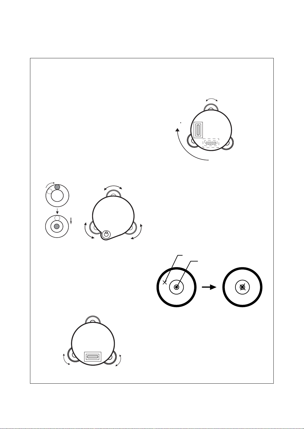
1 NOMENCLATURE AND FUNCTIONS
1 NOMENCLATURE AND FUNCTIONS
1.1 Nomenclature
Handgrip locking screw
Point guide
(Point guide type only)
Handgrip
Objective lens
Display unit
(Only for GPT-2003/
2005)
Circular level
Adjustment screw
for circular level
Tribrach fixing lever
Instrument
center mark
Optical plummet
telescope
(Optical plummet
telescope type only)
Leveling screw
Base
1-1
Page 13

Sighting collimator
1 NOMENCLATURE AND FUNCTIONS
Telescope focusing knob
Telescope grip
Telescope eyepiece
*Vertical motion clamp
*Vertical tangent screw
Plate level
Display unit
Battery locking lever
On-board battery
BT-52QA
Instrument
center mark
Horizontal
tangent screw
Horizontal
motion clamp
Power supply
connector
Serial Signal
connector
*The position of vertical motion clamp and Vertical tangent screw will differ depending on the market.
1-2
Page 14
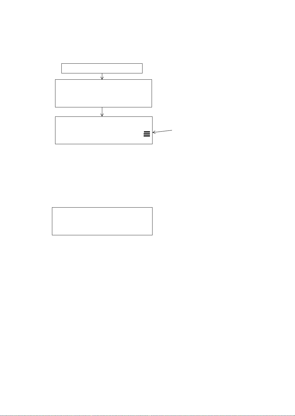
1.2 Display
HR: 120°30'40"
HD* 65.432 m
VD: 12.345 m
MEAS MODE NP/P P1
↓
HR: 120°30'40"
HD* 123.04.6f
VD: 12.03.4f
MEAS MODE NP/P P1
↓
●
Display
The display uses a dot matrix LCD which has 4 lines and 20 characters per line. In general, the
upper three lines display measured data, and the bottom line displays the soft key function which
changes with the measuring mode.
●
Contrast and Illumination
The contrast and illumination of display window are adjusted. See Chapter 6 “SPECIAL MODE
(Menu Mode)”.
●
Example
V : 90°10'20"
HR: 120°30'40"
1 NOMENCLATURE AND FUNCTIONS
0SET HOLD HSET P1
Angle measurement mode
V-angle : 90°10’20”
H-angle : 120°30’40”
Feet unit
↓
Distance measurement mode
Horizontal-angle : 120°30’40”
Horizontal distance : 65.432m
Relative elevation : 12.345m
Feet and inch unit
HR: 120°30'40"
HD* 123.45 f
VD: 12.34 f
MEAS MODE NP/P P1
Horizontal-angle : 120°30’40”
Horizontal distance : 123.45ft
Relative elevation : 12.34ft
●
Display marks
Display Contents Display Content
VV-angle
HR H-angle right m Meter unit
HL H-angle left f Feet unit / Feet and inch unit
↓
Horizontal-angle : 120°30’40”
Horizontal distance : 123ft4in6/8in
Relative elevation : 12ft3in4/8in
✻
EDM working
HD Horizontal distance
VD Relative elevation
SD Slope distance
NN coordinate
EE coordinate
ZZ coordinate
N
Switches non-prism mode or prism mode
P
1-3
Page 15
1 NOMENCLATURE AND FUNCTIONS
1.3 Operating Key
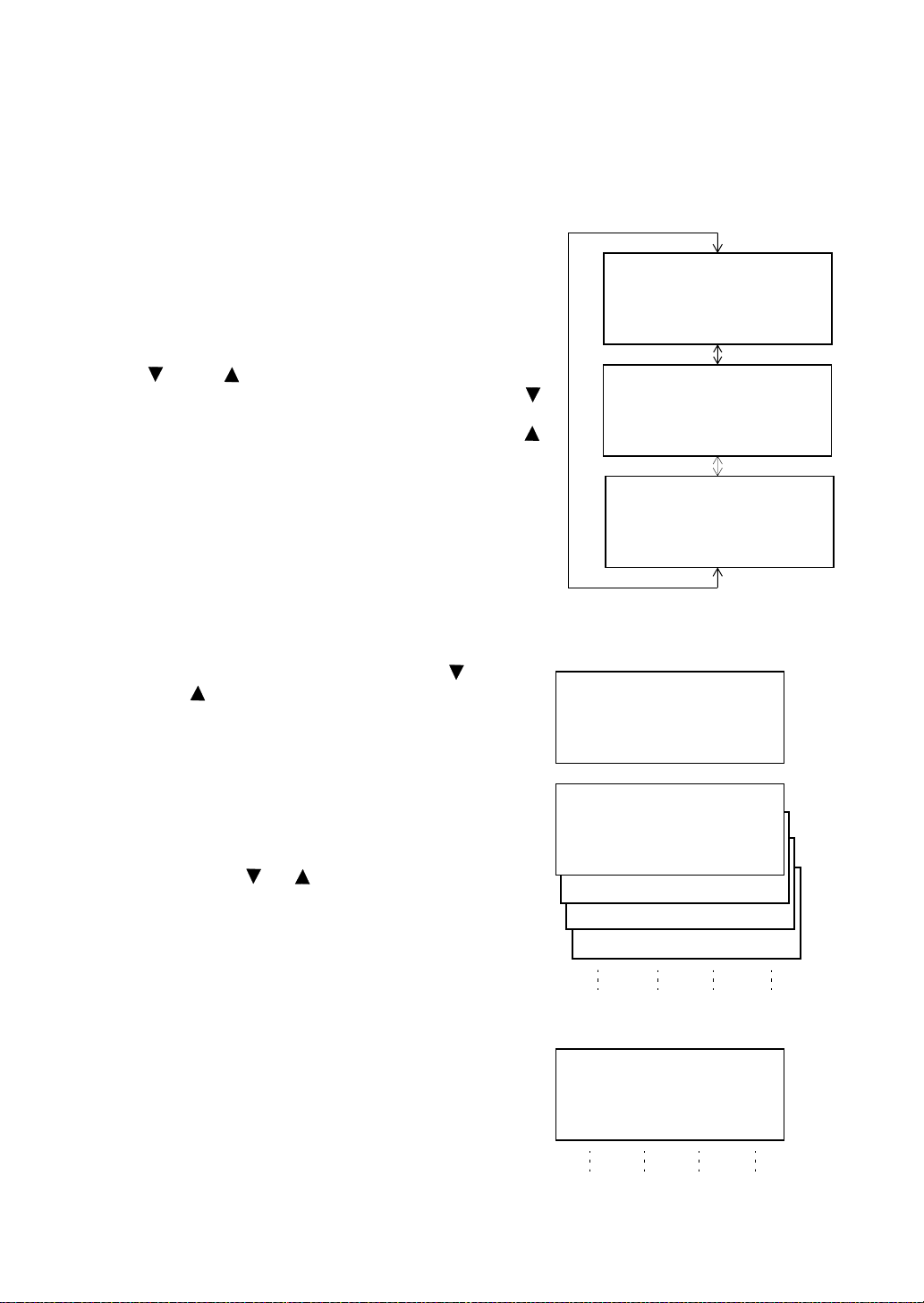
Keys Name of Key Function
Coordinate
meas.key
Distance meas.key Distance measurement mode.
ANG Angle meas.key Angle measurement mode
MENU Menu key
ESC Escape key
POWER Power source key ON/OFF of power source
F1–F4
Soft key
( Function key)
Coordinate measurement mode
Switches menu mode and normal mode. To set application measurements
and adjust in the menu mode.
● Returning to the measurement mode or previous layer mode from the
mode set.
● To be DATA COLLECTION mode or LAYOUT mode directly from the
normal measurement mode.
● It is also possible to use as Record key in normal measurement mode.
To select function of Escape key, see Chapter 16 “SELECTING MODE”
.
Responds to the message displayed.
1.4 Function Key (Soft Key)
The Soft Key message is displayed at the bottom line of display. The functions are according to the
displayed message.
Angle measurement mode Distance measurement mode
V: 90°10'20"
HR:120°30'40"
0SET HOLD HSET P1
TILT REP V% P2
H-BZ R/L CMPS P3
↓
↓
↓
HR:120°30'40"
HD*[r] <<m
VD: m
MEAS MODE NP/P P1
↓
OFSET S.O S/A P2
--- m/f/i --- P3
Coordinates measurement mode
↓
↓
[F1] [F2] [F3] [F4]
Soft keys
N: 123.456 m
E: 34.567 m
Z: 78.912 m
MEAS MODE NP/P P1
R.HT INSHT OCC P2
OFSET m/f/i S/A P3
1-4
↓
↓
↓
Page 16
Angle measurement
Soft
Page
1
2
3
Display
key
mark
F1 0SET Angle of Horizontal is set to 0°00'00"
F2 HOLD Hold the horizontal angle
F3 HSET Sets a required horizontal angle by entering numerals.
F4
P1
F1 TILT
F2 REP Repetition angle measurement mode
F3 V% Vertical angle percent grade(%) mode
F4
P2
F1 H-BZ Sets the buzzer sound for every horizontal angle 90°
F2 R/L Switches R/L rotation of horizontal angle.
F3 CMPS Switches the COMPASS ON/OFF of vertical angle.
F4
P3
The function of soft keys is shown on next page (P2).
↓
Setting Tilt Correction
If ON, the display shows tilt correction value.
The function of soft keys is shown on next page (P3).
↓
The function of soft keys is shown on next page (P1).
↓
Distance measurement mode
F1 MEAS Start measuring
F2 MODE Sets a measuring mode, Fine/Coarse/Tracking
1
F3 NP/P Switches non-prism mode or prism mode.
F4
P1
F1 OFSET Select Off-set measurement mode
F2 S.O Select stake out measurement mode
2
F3 S/A Select set audio mode
F4
P2
F2 m/f/i Switches meter, feet or feet and inch unit.
3
F4
P3
The function of soft keys is shown on next page (P2).
↓
The function of soft keys is shown on next page (P3).
↓
The function of soft keys is shown on next page (P1).
↓
1 NOMENCLATURE AND FUNCTIONS
Function
Coordinate measurement mode
F1 MEAS Start measuring
F2 MODE Sets a measuring mode, Fine/Coarse/Tracking
1
F3 NP/P Switches non-prism mode or prism mode.
F4
P1
F1 R.HT Sets a prism height by input values.
F2 INSHT Sets an instrument height by input values.
2
F3 OCC Sets an instrument coordinate point by input values.
F4
P2
F1 OFSET Select Off-set measurement mode
F2 m/f/i Switches meter, feet or feet and inch unit.
3
F3 S/A Select set audio mode
F4
P3
The function of soft keys is shown on next page (P2).
↓
The function of soft keys is shown on next page (P3).
↓
The function of soft keys is shown on next page (P1).
↓
1-5
Page 17

1 NOMENCLATURE AND FUNCTIONS
1.5 Serial signal RS-232C connector
The serial signal connector is used for connecting the GPT-2000 series with a computer or TOPCON
Data Collector, which enables the computer to receive measured data from the GPT-2000 series or to
send preset data of horizontal angle, etc. to it.
● The following data will be output at each mode.
Mode Output
Angle mode ( V,HR or HL) ( V in percent) V,HR (or HL)
Horizontal distance mode (HR, HD, VD) V,HR, HD, VD
Slope distance mode (V, HR,SD) V,HR, SD,HD
Coordinate mode
● The display and the output at the coarse mode are the same as the contents above.
● Output at the tracking mode is displayed as distance data only.
The details necessary for the connection with the GPT-2000 Series are obtained from its Interface
Manual which is optionally available. Please refer to the manual.
N, E, Z, HR (or V,H,SD,N,E,Z)
1-6
Page 18
2 PREPARATION FOR MEASUREMENT
2 PREPARATION FOR MEASUREMENT
2.1 Power Connection
(unnecessary if on-board Ni-MH battery BT-52QA is used)
See below for connecting the external battery pack.
● Battery pack BT-3Q
Power cord , PC-5 is used.
● Large capacity battery pack BT-3L
Power cord PC-6 is used.
Cable
PC-5
PC-6
Battery pack
BT-3Q
BT-3L
Connector ends
PC-5
PC-6
Note: BT-32Q on-board (Ni-Cd) battery can be also available.
To use BT -32Q (Ni-Cd) battery, it is required to change battery type in selecting mode, see
Section 6.4.5 “Selecting Battery Type”.
2-1
Page 19
2 PREPARATION FOR MEASUREMENT
2.2 Setting Instrument Up For Measurement
Mount the instrument to the tripod. Level and center the instrument precisely to insure the best
performance. Use tripods with a tripod screw of 5/8 in. diameter and 11 threads per inch, such as the
Type E TOPCON wide- frame wooden tripod.
Reference: Leveling and Centering the Instrument
1. Setting up the Tripod
First, extend the extension legs to suitable lengths
and tighten the screws on their midsections.
2. Attaching the Instrument on the Tripod
Head
Place the instrument carefully on the tripod head
and slide the instrument by loosening the tripod
screw . If the plumb bob is positioned right over the
center of the point, slightly tighten the tripod
screw.
3. Roughly Leveling the Instrument by Using
the Circular Level
1 Turn the leveling screws A and B to move the
bubble in the circular level. The bubble is now
located on a line perpendicular to a line
running through the centers of the two leveling
screws being adjusted.
Leveling screw C
Leveling
screw A
2 Turn the leveling screw C to bring the bubble
to the center of the circular level.
4. Centering by Using the Plate Level
1 Rotate the instrument horizontally by using
the Horizontal motion/clamp screw and place
the plate level parallel with the line connecting
leveling screws A and B, and then bring the
bubble to the center of the plate level by
turning leveling screws A and B.
Leveling screw B
2 Rotate the instrument 90° (100gon) around its
vertical axis and turn the remaining leveling
screw or C to center the bubble once more.
Leveling screw C
90
90°
3 Repeat the procedures 1 and 2 for each 90°
(100gon) rotation of the instrument and check
whether the bubble is correctly centered for all
four points.
5. Centering by Using the Optical Plummet
Telescope
Adjust the eyepiece of the optical plummet
telescope to your eyesight.
Slide the instrument by loosening the tripod
screw, place the point on the center mark, and
then tighten the tripod screw. Sliding the
instrument carefully not to rotate that allows you
to get the least dislocation of the bubble.
Point
Center mark
Leveling
screw A
6. Completely Leveling the Instrument
Leveling the instrument precisely in a similar way
to 4. Rotate the instrument and check to see that
the bubble is in the center of the plate level
regardless of telescope direction, then tighten the
tripod screw hard.
Leveling
screw B
2-2
Page 20
2.3 Power Switch Key ON
1 Confirm the instrument is leveled.
2 Press the power key..
Press the power key
TOPCON GPT-2000
V : 90°10'20"
HR: 0°00'00"
2 PREPARATION FOR MEASUREMENT
Battery Power Remaining Display
0SET HOLD HSET P1
● Confirm the battery power remaining display. Replace with charged battery or charge when battery
level is low or indicates “Battery empty”. see Section 2.4“Battery Power Remaining Display” .
● Contrast adjustment
You can confirm prism constant value (PSM), non-prism constant value (NPM), atmospheric
correction value (PPM) and you can also adjust the contrast of the display when the instrument is
turned on.
To display this screen, see Chapter 16 “SELECTING MODE” .
↓
CONTRAST ADJUSTMENT
PSM: 0.0 PPM 0.0
NPM: 0.0
↓ ↑ - - - ENTER
This enables you to adjust the brightness by pressing the [F1](
To memorize the setting value after powering off, press [F4](ENTER) key.
↓
) or [F2](↑) key.
2-3
Page 21
2.4 Battery Power Remaining Display
Battery power remaining display indicates the power condition.
V : 90°10'20"
HR: 0°00'00"
2 PREPARATION FOR MEASUREMENT
Measurement is possible.
0SET HOLD HSET P1
Battery power remaining display
Note: 1 The battery operating time will vary depending on the environmental conditions such as
ambient temperature, charging time, the number of times of charging and discharging etc.
It is recommended for safety to charge the battery beforehand or to prepare spare full
charged batteries.
2For general usage of the battery, see Chapter 14 “POWER SOURCE AND CHARGING” .
3 The battery power remaining display shows the power level regarding to the
measurement mode now operating.
The safety condition indicated by the battery power remaining display in the angle
measurement mode does not necessarily assure the battery’s ability to be used in the
distance measurement mode.
It may happen that the mode change from the angle mode to the distance mode will stop
the operation because of insufficient battery power for the distance mode which
consumes more power than angle mode.
↓
The power is poor. The battery
should be recharged or replaced.
Blinking
<Battery empty>
Other displays disappear.
Measurement is impossible.
Need to recharge or replace
the battery.
2-4
Page 22

2 PREPARATION FOR MEASUREMENT
2.5 Vertical and Horizontal Angle Tilt Correction
(GPT-2009 has vertical angle tilt correction only.)
When the tilt sensors are activated, automatic correction of vertical and horizontal angle for
mislevelment is displayed.
To ensure a precise angle measurement, tilt sensors must be turned on. The display can also be used
to fine level the instrument. If the (TILT OVER) display appears the instrument is out of automatic
compensation range and must be leveled manually.
Zenith
Zenith
Standing axis
Standing axis
Inclination of the standing
axis in the X direction
Inclination of the standing
axis in the Y direction
Horizontal
● GPT-2000 compensates both the vertical angle and the horizontal angle readings due to inclination
of the standing axis in the X and Y directions .
● For more information about dual axis compensation, refer to APPENDIX 1 “Dual Axis
Compensation”.
When the instrument is out of compensation. (TILT OVER)
V : ° ' "
HR: ° ' "
<X TILT OVER>
Standing Axis in the X direction
out of range
V : ° ' "
HR: ° ' "
<Y TILT OVER>
Standing Axis in the Y direction
out of range
V : ° ' "
HR: ° ' "
<XY TILT OVER>
Standing Axis in the X and Y
directions out of range
Trunnion axis
● The display of Vertical or Horizontal angle is unstable when instrument is on an unstable stage or a
windy day. You can turn off the auto tilt correction function of V/H angle in this case.
● To set auto tilt correction from the moment that power is on, see Section 6.4.3“Vertical and
Horizontal Angle Tilt correction ( Tilt ON/OFF)” .
2-5
Page 23
● Setting Tilt Correction by Soft Key
To enable you to select tilt ON/OFF function. setting is not memorized after power is OFF.
[Example] Setting X,Y Tilt OFF
Operating procedure Option Display
1 Press [F4] key to get the function page 2.
2 PREPARATION FOR MEASUREMENT
[F4]
V : 90°10'20"
HR: 120°30'40"
0SET HOLD HSET P1
TILT REP V% P2
2 Press [F1](TILT) key.
In case ON is already selected, the display shows
tilt correction value.
[F1]
TILT SENSOR:[XY-ON]
X:-0°00'25"
Y: 0°00'20"
X-ON XY-ON OFF ---
3 Press [F3](OFF) key.
[F3]
TILT SENSOR: [OFF]
X-ON XY-ON OFF ---
4 Press [ESC] key.
[ESC]
V : 90°10'20"
HR: 120°30'40"
TILT REP V% P2
● The setting mode performed here will not be memorized after powering OFF. To set TILT correction in
the initialized setting ( it is memorized after powering OFF), see Section 6.4.3“Vertical and Horizontal
Angle Tilt correction ( Tilt ON/OFF)” .
↓
↓
↓
2-6
Page 24
2 PREPARATION FOR MEASUREMENT
2.6 How to Enter Alphanumeric characters
This enables you to enter alphanumeric characters such as the instrument height, prism height,
occupied point, backsight point etc..
● How to select a item
[Example setting] Occupied point in the data collection mode.
The arrow indicates a item to enter.
The arrow line moves up or down when the
[] key or [ ] key is pressed.
● How to enter characters
1 Move the arrow to enter a item using the [ ]
or [ ] key.
2 Press the [F1] (INPUT) key.
The arrow changes to the equal (=) .
The characters are displayed on the bottom
line.
3 Press the [ ] or [ ] key to select a page.
PT# →ST-01
ID :
INS.HT: 0.000 m
INPUT SRCH REC OCNEZ
[]
or
[]
PT# :ST-01
ID
→
INS.HT: 0.000 m
INPUT SRCH REC OCNEZ
PT# :ST-01
ID :
INS.HT→ 0.000 m
INPUT SRCH REC OCNEZ
PT#
→
ID :
INS.HT: 0.000 m
INPUT SRCH REC OCNEZ
PT# =
ID :
INS.HT: 0.000 m
1234 5678 90.- [ENT]
ABCD EFGH IJKL [ENT]
4 Press the soft key to select a group of
characters.
Example: [F2](QRST) key is pressed.
MNOP QRST UVWX [ENT]
YZ+#[SPC][CLR][ENT]
[F1] [F2] [F3] [F4]
PT# =
ID :
INS.HT: 0.000 m
(Q) (R) (S) (T)
[F1] [F2] [F3] [F4]
2-7
Page 25
2 PREPARATION FOR MEASUREMENT
5 Press soft key to select a character.
PT# =T
ID :
Example: [F4](T) key is pressed.
Select next character in the same manner.
INS.HT: 0.000 m
MNOP QRST UVWX [ENT]
PT# =TOPCON-1
ID :
INS.HT : 0.000 m
MNOP QRST UVWX [ENT]
6 Press [F4](ENT) key.
The arrow moves to next item.
Select next character in the same manner.
● To correct a character, move the cursor to correct character by pressing [ ] or [ ] key and enter
again.
PT# :TOPCON-1
ID
→
INS.HT : 0.000 m
INPUT SRCH REC OCNEZ
2.7 Point Guide (Only for Point Guide type)
Fast and simple to use, the Point Guide feature is useful when doing stake out work. The LED’s for the
Point Guide System on the instrument telescope assist the rod person to get on-line. When using the
Point Guide System, the battery life will be approximately 8 hours at +20 °C (+68 °F).
Turning the Point Guide ON and Operation:
Press the [MENU] key to get the menu screen and press the
[MENU] key again. Point Guide LED
Looking at the objective lens of the telescope, the right LED
will blink and the left LED will stay lit.
’s will be turned ON.
Instrument
The Point Guide should be used within a distance of 100
meters (328 feet). The quality of its results will depend on the
weather conditions and the user
The goal of the rod person is to look at both LED
instrument and move the prism on-line until both LED
equally bright.
● If the solid LED is brighter, move right.
● If the blinking LED is brighter, move left.
Once you have determined that both of the LED's are equally bright, you are on-line with the
instrument.
Turning the Point Guide OFF:
To turn OFF the Point Guide System, press the [MENU] key again in menu screen.
The point guide function can be available while executing Layout mode. See 8.2 “Executing a Layout”.
’s eyesight.
’s on the
’s are
Illuminate
Blink
Prism
2-8
Page 26
2 PREPARATION FOR MEASUREMENT
2.8 Laser Plummet ON/OFF (Only for Laser Plummet type)
Laser plummet option will help you to center the instrument easily onto the measurement point.
There are two ways to turn on/off of laser plummet option as follows.
● On/Off of laser plummet option by Soft Key in Tilt Correction
Operating procedure Option Display
1 Press the [F4] key to get the function page 2.
[F4]
V : 90°10'20"
HR: 120°30'40"
2 Press the [F1](TILT) key.
In case ON is already selected, the display shows
tilt correction value.
3 Press the [F4](L.PL) key.
By pressing the [F4](L.PL) key, the laser plummet
will be turned On / Off alternately.
● Symbol mark while the laser is emitting.
The following symbol mark will appear at the right side of the second line.
[F1]
[F4]
TILT SENSOR:[XY-ON]
X:-0°00'25"
Y: 0°00'20"
X-ON XY-ON OFF L.PL
● On/Off of laser plummet option from MENU mode
Operating procedure Operation Display
1 Press the [MENU] key.
2 Press the [F4](P
↓
) key to get the menu on page 2.
3 Press the [F3] key.
[MENU]
[F4]
[F3]
0SET HOLD HSET P1
TILT REP V% P2
TILT SENSOR:[XY-ON]
X:-0°00'25"
Y: 0°00'20"
X-ON XY-ON OFF L.PL
TILT SENSOR:[XY-ON]
X:-0°00'25"
Y: 0°00'20"
X-ON XY-ON OFF L.PL
Symbol mark
MENU 1/3
F1:DATA COLLECT
F2:LAYOUT
F3:MEMORY MGR. P
↓
MENU 2/3
F1:PROGRAMS
F2:GRID FACTOR
F3:LASER PLUMMET P
LASER PLUMMET [OFF]
F1:ON
F2:OFF
↓
↓
↓
4 Press the [F1] or [F2] key to turn on or off the laser
plummet option.
[F1] or [F2]
LASER PLUMMET [ON]
F1:ON
F2:OFF
Laser Plummet auto-cut off function
The laser plummet will be turned off automatically after 1 to 99 minutes (Default :3 minutes). It is also
possible to stop the auto-cut off function.
Refer to Chapter 16 “SELECTING MODE” to change the time or to invalidate the function.
2-9
Page 27
3 ANGLE MEASUREMENT
3 ANGLE MEASUREMENT
3.1 Measuring Horizontal Angle Right and Vertical Angle
Make sure the mode is in Angle measurement.
Operating procedure Operation Display
1 Collimate the 1st target (A).
Collimate A
V : 90°10'20"
HR: 120°30'40"
0SET HOLD HSET P1
2 Set horizontal angle of target A at 0° 00' 00".
Press the [F1](0 set) key and press the [F3](YES)
key .
[F1]
H ANGLE 0 SET
> OK?
--- --- [YES][NO]
[F3]
V : 90°10'20"
HR: 0°00'00"
0SET HOLD HSET P1
3 Collimate the 2nd target (B).
The required V/H angle to target B will be
displayed.
Collimate B
V : 98°36'20"
HR: 160°40'20"
0SET HOLD HSET P1
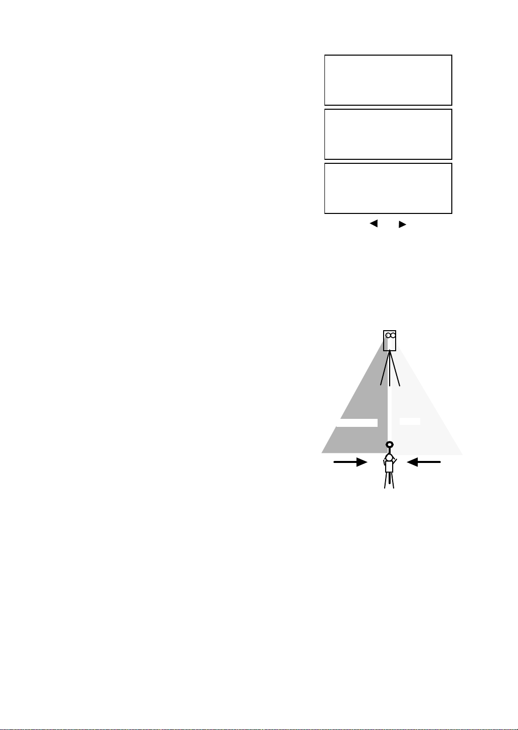
Reference : How to Collimate
1 Point the telescope toward the light. Turn the diopter ring and adjust the diopter so that the cross
hairs are clearly observed.
(Turn the diopter ring toward you first and then backward to focus.)
2 Aim the target at the peak of the triangle mark of the sighting collimator. Allow a certain space
between the sighting collimator and yourself for collimating.
3 Focus the target with the focusing knob.
↓
↓
↓
*If parallax is created between the cross
hairs and the target when viewing
vertically or horizontally while looking
into the telescope, focusing is incorrect
ordiopter adjustment is poor. This
adversely affects precision in
measurement or survey Eliminate the
parallax by carefully focusing
and using diopter adjustment.
3-1
Focusing knob
Telescope eyepiece (Diopter ring)
∞
∞
∞
∞
Page 28
3.2 Switching Horizontal Angle Right/Left
Make sure the mode is Angle measurement.
Operating procedure Operation Display
1
Press the [F4](
on page 3.
↓
) key twice to get the function
twice
[F4]
3 ANGLE MEASUREMENT
V : 90°10'20"
HR: 120°30'40"
0SET HOLD HSET P1
TILT REP V% P2
H-BZ R/L CMPS P3
2
Press the [F2](R/L) key.
The mode Horizontal angle Right (HR)
switches to (HL) mode.
[F2]
V : 90°10'20"
HL: 239°29'20"
H-BZ R/L CMPS P3
3
Measure as HL mode.
Every time pressing the [F2](R/L) key, HR/HL mode switches.
3.3 Measuring from the Required Horizontal Angle
3.3.1 Setting by Holding the Angle
Make sure the mode is angle measurement .
Operating procedure Operation Display
1
Set the required horizontal angle, using
Horizontal tangent screw
Display angle
V : 90°10'20"
HR: 130°40'20"
0SET HOLD HSET P1
↓
↓
↓
↓
↓
2
Press the [F2](HOLD) key.
3
Collimate the target.
4
Press the [F3](YES) key to finish holding the
horizontal angle.*1)
The display turns back to normal angle
measurement mode.
*1) To return to the previous mode, press the [F4](NO) key.
3-2
[F2]
Collimate
[F3]
H ANGLE HOLD
HR= 130°40'20"
> SET ?
--- --- [YES][NO]
V : 90°10'20"
HR: 130°40'20"
0SET HOLD HSET P1
●
↓
Page 29
3.3.2 Setting a Horizontal Angle from the Keys
Make sure the mode is Angle measurement .
Operating procedure Operation Display
1
Collimate the target.
Collimate
3 ANGLE MEASUREMENT
V : 90°10'20"
HR: 170°30'20"
0SET HOLD HSET P1
2
Press the [F3](HSET) key.
[F3]
H ANGLE SET
HR:
INPUT --- --- ENTER
1234 5678 90.-[ENT]
3
Input the required horizontal angle by
using keys. *1)
For example :70°40'20"
When completed, normal measuring from the
required Horizontal angle is possible.
*1) To enter Alphanumeric characters, see Section 2.6 “How to Enter Alphanumeric characters” .
[F1]
70.4020
[F4]
V : 90°10'20"
HR: 70°40'20"
0SET HOLD HSET P1
3.4 Vertical Angle Percent Grade(%) Mode
Make sure the mode is Angle measurement .
Operating procedure Operation Display
1
Press the [F4](↓) key to get the function on page 2.
[F4]
V : 90°10'20"
HR: 170°30'20"
0SET HOLD HSET P1
TILT REP V% P2
↓
↓
↓
↓
2
Press the [F3](V%) key. *1)
[F3]
V : -0.30 %
HR: 170°30'20"
TILT REP V% P2
*1) Every time pressing the [F3](V%) key, the display mode switches.
●
When the measurement is carried out over ±45° (±100%) from the horizontal, the display shows
<OVER>.
3-3
↓
Page 30
3.5 Repetition Angle Measurement
●
Repetition angle measurement can be done by horizontal angle right measurement mode.
Make sure the mode is Horizontal Angle Right measurement.
Operating procedure Operation Display
1
Press the [F4](↓) key to get the function on page 2.
[F4]
3 ANGLE MEASUREMENT
V : 90°10'20"
HR: 170°30'20"
2
Press the [F2](REP)key.
3
Press the [F3](YES) key.
4
Collimate the target A and press the [F1] (0SET)
key .
5
Press the [F3] (YES) key.
6
Collimate the target B using the horizontal clamp
and tangent screw.
Press the [F4](HOLD) key.
[F2]
[F3]
Collimate A
[F1]
[F3]
Collimate B
[F4]
0SET HOLD HSET P1
TILT REP V% P2
↓
↓
REPETITION ANGLE
> OK?
--- --- [YES][NO]
REP-ANGLE COUNT[ 0]
Ht: 0°00'00"
Hm:
0SET V/H REL HOLD
REPETITION ANGLE
INITIALIZE
> OK?
--- --- [YES][NO]
REP-ANGLE COUNT[ 0]
Ht: 0°00'00"
Hm:
0SET V/H REL HOLD
REP-ANGLE COUNT[ 1]
Ht: 45°10'00"
Hm: 45°10'00"
0SET V/H REL HOLD
7
Recollimate target A using the horizontal clamp
and tangent screw, and press the [F3](REL)key.
8
Recollimate target B using the horizontal clamp
and tangent screw, and press the [F4](HOLD) key.
9 Repeat 7 to 8 to measure the desired number of
repetitions.
3-4
Collimate A
[F3]
Collimate B
[F4]
REP-ANGLE COUNT[ 1]
Ht: 45°10'00"
Hm: 45°10'00"
0SET V/H REL HOLD
REP-ANGLE COUNT[ 2]
Ht: 90°20'00"
Hm: 45°10'00"
0SET V/H REL HOLD
REP-ANGLE COUNT[ 4]
Ht: 180°40'00"
Hm: 45°10'00"
0SET V/H REL HOLD
[Example] 4 measurement
Page 31

3 ANGLE MEASUREMENT
10 To return to the normal angle mode, press the
[F2](V/H) key or [ESC] key.
[ESC]
or
[F2]
REPETITION ANGLE
Exit
> OK?
--- --- [YES][NO]
11 Press the [F3](YES) key.
[F3]
V : 90°10'20"
HR: 170°30'20"
0SET HOLD HSET P1
● Horizontal angle can be accumulated up to
(3600°00'00" – minimum reading) (horizontal angle right).
In case of 5 second reading, horizontal angle can be accumulated up to +3599°59'55".
● Error will be displayed when the results differ from first measurement by more than ±30".
3.6 Buzzer Sounding for Horizontal Angle 90° Increments
When the horizontal angle falls in the range of less than ± 1° of 0°, 90°, 180° or 270°, the buzzer
sounds. Buzz er stops only when the horizontal angle is adjusted to 0°00’00”, 90°00’00” , 180°00’00” or
270°00’00”.
This setting is not memorized after powering off. Refer to 16 “SELECTING MODE” to set the initial
setting (memorized after powering off).
Make sure the mode is Angle measurement.
Operating procedure Operation Display
1 Press the [F4](
on page 3.
↓
) key twice to get the function
[F4]
twice
V : 90°10'20"
HR: 170°30'20"
↓
2 Press the [F1](H-BZ) key.
The data previously set is shown.
3 Press the [F1](ON) key or [F2](OFF) key to select
the buzzer ON/OFF.
4 Press the [F4](ENTER) key.
[F1]
[F1] or [F2]
[F4]
0SET HOLD HSET P1
H-BZ R/L CMPS P3
H-ANGLE BUZZER [OFF]
[ON] [OFF] --- ENTER
H-ANGLE BUZZER [ON]
[ON] [OFF] --- ENTER
V : 90°10'20"
HR: 170°30'20"
0SET HOLD HSET P1
↓
↓
↓
3-5
Page 32

3.7 Compasses ( vertical angle)
Vertical angle is displayed as shown below.
3 ANGLE MEASUREMENT
+90°
0°
-90°
Operating procedure Operation Display
1 Press the [F4](
on page 3.
2 Press the [F3](CMPS) key. *1)
*1) Every time pressing the [F3](CMPS) key, the display mode switches.
↓
) key twice to get the function
[F4]
twice
[F3]
0°
V : 98°10'20"
HR: 170°30'20"
0SET HOLD HSET P1
H-BZ R/L CMPS P3
V : - 8°10'20"
HR: 170°30'20"
H-BZ R/L CMPS P3
↓
↓
↓
3-6
Page 33
4 DISTANCE MEASUREMENT
N: 120.456 m
E: 34.567 m
N
P
Z: 12.345 m
MEAS MODE NP/P P1
↓
4 DISTANCE MEASUREMENT
Note: Those distance shorter than 2.5m will not be displayed in Non-prism mode.
● Prism mode and Non-prism mode
In GPT-2000 series, the distance measurement will be done using invisible pulse laser beam emitted
from pulse laser diode. You can select measurement mode between Prism mode which collimating a
prism and Non-prism mode that is collimating a target object except prism.
● Non-prism mode enables all distance measurements such Distance measurement, Coordinate
measurement, Offset measurement and Layout.
● To switch over Prism mode to Non-prism mode or contrary, press the [NP/P] soft key in each
measurement display. [NP] of Non-prism mode indicator will be shown at the right corner of the
display in Non-prism mode measurement.
Changing mode shall be done before measurement.
Example
● It is possible to set Non-prism mode for distance measurement during the power on time. Refer to
● If happened collimating the near distance prism in Non-prism mode, measurement will not be done
Distance measurement mode
HR: 120°30'40"
HD* 65.432 m
N
P
VD: 12.345 m
MEAS MODE NP/P P1
To change the mode, press the [NP/P] soft key in each measurement.
16.SELECTING MODE to set the option.
because of too much light.
↓
Non-prism
mode
indicator
Coordinate measurement mode
4.1 Setting of the Atmospheric Correction
When setting the atmospheric correction, obtain the correction value by measuring the temperature
and pressure. Refer to Section 12.2 “Setting of Atmospheric Correction Value”.
4.2 Setting of the Correction for Prism Constant / Non-prism Constant
Topcon’s prism constant value is 0. Set correction f or prism at 0. If the prism is of another manufacture,
the appropriate constant shall be set beforehand. Refer to Chapter 11 “SETTING THE PRISM / NONPRISM CONSTANT VALUE”. The setting value is kept in the memory even after power is off.
Note: Confirm that Non-prism correction value is set at zero before measurement target such
as a wall in Non-prism mode.
4-1
Page 34
4 DISTANCE MEASUREMENT
4.3 Distance Measurement (Continuous Measurement)
Make sure the mode displays angle measurement.
Operating procedure Operation Display
1 Collimate the center of prism.
Collimate P
V : 90°10'20"
HR: 120°30'40"
2 Press the [ ] key.
Distance measurement starts. *1),2)
[ ]
0SET HOLD HSET P1
HR: 120°30'40"
HD*[r] << m
↓
VD: m
The measured distances are shown. *3)~*5)
MEAS MODE NP/P P1
HR: 120°30'40"
↓
HD* 123.456 m
VD: 5.678 m
MEAS MODE NP/P P1
● Pressing the [ ] key again, the display
changes to horizontal (HR) and vertical (V)angle
and slope distance(SD). *6)
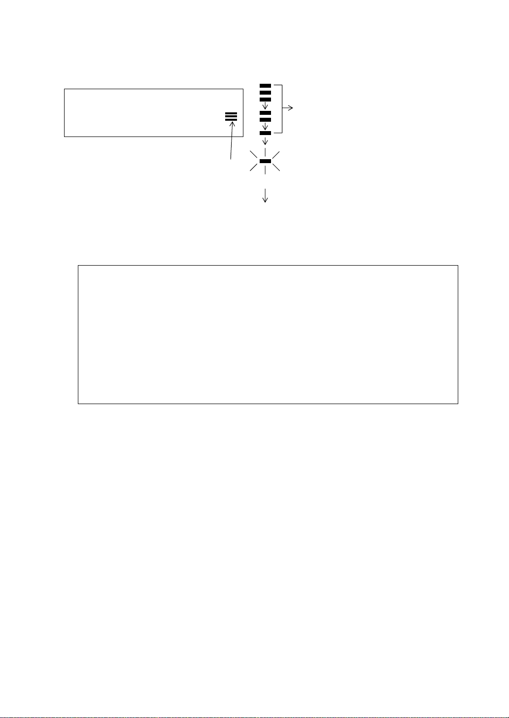
*1) When EDM is working, the "✻ " mark appears in the display.
*2) To change mode from Fine to Coarse or Tracking, refer to section 4.5 “Fine Mode/Tracking Mode/
Coarse Mode”.
To set the distance measurement on when the instrument is powered on, refer to Chapter 16
“SELECTING MODE”.
*3) The distance unit indicator "m" (for meter) , "f" (for feet or feet inch) appears and disappears alternatively
with buzzer sounds at every renewal of distance data.
*4) Measurement may repeat automatically in the instrument if the result is affected by shimmer etc..
*5) To return to the normal measuring angle mode from a distance measuring mode, press the [ANG] key.
*6) It is possible to choose the display order (HR, HD, VD) or (V, HR, SD) for initial measuring distance
mode. Refer to Chapter 16 “SELECTING MODE”.
[ ]
V : 90°10'20"
HR: 120°30'40"
SD* 131.678 m
MEAS MODE NP/P P1
↓
↓
4-2
Page 35
4 DISTANCE MEASUREMENT
4.4 Distance Measurement
When the number of times measurement is preset, the GPT-2000 series measures the distance the set
number of times. The average distance will be displayed.
When presetting the number of times as 1, it does not display the average distance, because of single
measurement. Single measurement is set at the factory.
Make sure the mode displays angle measurement.
Operating procedure Operation Display
1 Collimate the center of prism.
(N-time Measurement/Single Measurement)
V : 90°10'20"
HR: 120°30'40"
0SET HOLD HSET P1
2 Press the [ ] key.
Continuous measuring starts.*1)
[ ]
HR: 120°30'40"
HD*[r] << m
VD: m
MEAS MODE NP/P P1
3 Press [F1](MEAS) key while continuous
measuring is exceeding. *2)
The average value is displayed and "*" mark
disappears.
● While EDM is working, press [F1](MEAS) key
again, the mode will be changed to continuous
measuring mode.
[F1]
HR: 120°30'40"
HD*[n] << m
VD: m
MEAS MODE NP/P P1
HR: 120°30'40"
HD: 123.456 m
VD: 5.678 m
MEAS MODE NP/P P1
↓
↓
↓
↓
*1) It is possible to set the measurement mode for N-times measurement mode or continuous
measurement mode when the power is turned on. Refer to Chapter 16 “SELECTING MODE”.
*2) For setting the number of times (N-times) in the measurement, refer to Chapter 16 “SELECTING
MODE”.
4-3
Page 36

4 DISTANCE MEASUREMENT
● Choose meter /feet / feet+inch unit by soft key
It is possible to change the unit for distance measurement mode by soft key.
This setting is not memorized after power off. Refer to 16 “SELECTING MODE” to set at the initial
setting (memorized after power off).
Operating procedure Operation Display
1 Press the [F4](P1
on page 3.
↓
) key twice to get the function
[F4]
HR: 120°30'40"
HD* 2.000 m
VD: 3.000 m
MEAS MODE NP/P P1
OFSET S.O S/A P2
--- m/f/i --- P3
2 Every time pressing the [F2](m/f/i) key, the display
unit will be changed.
● Every time pressing the [F2](m/f/i) key, the unit
mode switches.
[F2]
HR: 120°30'40"
HD* 6.560 f
VD: 9.845 f
--- m/f/i --- P3
4.5 Fine Mode/Tracking Mode/Coarse Mode
This setting is not memorized after power is off. Refer to Chapter 16”SELECTING MODE” to set at the
initial setting (memorized after power is off).
•Fine Mode : This is a normal distance measuring mode.
•Tracking Mode : This mode measures in shorter time than in fine mode.
•Coarse Mode : This mode measures in shorter time than in fine mode.
The unit to be displayed: 0.2mm or 1mm. (0.001ft or 0.005ft)
Measurement time 0.2mm mode: approx. 3.0 sec.
1mm mode: approx. 1.2 sec.
It is very useful when tailing the moving object or carrying out stake-out work.
The unit to be displayed: 10mm
Measuring time: approx. 0.3 sec.
The unit to be displayed: 10mm or 1mm
Measuring time: approx. 0.5 sec.
↓
↓
↓
↓
Operating procedure Operation Display
1 Press the [F2](MODE) key from the distance
measuring mode.*1)
The initial character (F/T/C) of set mode is
displayed . (F:Fine, T:Tracking, C:Coarse)
2 Press the [F1](FINE) key, [F2](TRACK) key, or
[F3](COARSE) key.
*1) To cancel the setting, press the [ESC] key.
4-4
[F2]
[F1]~[F3]
HR: 120°30'40"
HD* 123.456m
VD: 5.678m
MEAS MODE NP/P P1
HR: 120°30'40"
HD* 123.456m
VD: 5.678m
FINE TRACK COARSE F
HR: 120°30'40"
HD* 123.456m
VD: 5.678m
MEAS MODE NP/P P1
↓
↓
Page 37

4 DISTANCE MEASUREMENT
4.6 Stake Out (S.O)
The difference between the measured distance and the input stake out distance is displayed.
Measured distance — Stake out distance = Displayed value
● In stake out operation, you can select either horizontal distance (HD), relative elevation (VD) and
slope distance (SD)
Operating procedure Operation Display
1 Press the [F4](
mode to get the function on page 2.
↓
) key in the distance measuring
[F4]
HR: 120°30'40"
HD* 123.456 m
VD: 5.678 m
MEAS MODE NP/P P1
OFSET S.O S/A P2
↓
↓
2 Press the [F2](S.O) key.
The data previously set is shown.
3 Select the measuring mode by pressing the [F1] to
[F3] key.
Example : Horizontal distance
4 Enter the distance for stake out. *1)
5 Collimate the target (Prism).
Measuring starts.
The difference between the measured distance
and the stake out distance is displayed.
6 Move the target until the difference becomes 0m.
[F2]
[F1]
[F1]
Enter data
[F4]
Collimate P
STAKE OUT
HD : 0.000 m
HD VD SD ---
STAKE OUT
HD : 0.000 m
INPUT --- --- ENTER
1234 5678 90.-[ENT]
STAKE OUT
HD : 100.000 m
INPUT --- --- ENTER
HR: 120°30'40"
dHD*[r] << m
VD: m
MEAS MODE NP/P P1
HR: 120°30'40"
dHD* 23.456 m
VD: 5.678 m
MEAS MODE NP/P P1
↓
↓
*1) Refer to section 2.6 “How to Enter Alphanumeric characters”.
● To return to normal distance measurement mode, stake out distance to "0" or turn the power off.
4-5
Page 38

4 DISTANCE MEASUREMENT
4.7 Offset Measurement
There are four offset measurement modes in the Offset Measurement.
● Angle offset
● Distance offset
● Plane offset
● Column offset
To show the offset measurement menu, press the [OFSET] soft key from distance or coordinate
measurement mode.
Example:
Distance measurement
HR: 120°30'40"
HD: 123.456 m
VD: 5.678 m
MEAS MODE NP/P P1
OFSET S.O S/A P2
Press the [F1](OFSET) key.
↓
↓
Coordinate measurement
N: 123.456 m
E: 34.567 m
Z: 78.912 m
MEAS MODE NP/P P1
R.HT INSHT OCC P2
OFSET m/f/i S/A P3
Press the [F1](OFSET) key.
↓
↓
↓
Offset Measurement Menu
OFFSET 1/2
F1:ANG.OFFSET
F2:DIST.OFFSET
F3:PLANE OFFSET P
[F4]
↓
OFFSET 2/2
F1:COLUMN OFFSET
P
↓
● Outputting the Measurement Data
The results of offset measurement can be output to external device.
Setting the function of the [ESC] key to (REC), the [F3] soft key which assigned (REC) will appear in
measured result display.
Refer to Chapter 16 “SELECTING MODE” to set this option.
OFFSET-MEASUREMENT
HR: 120°30'40"
SD: 123.456 m
NEXT --- REC ---
[F3]
● Distance measurement mode of the offset measurement
Offset measurement will be done by N-time fine measurement mode.
For setting measuring times refer to Chapter 16 “SELECTING MODE”.
4-6
Page 39

4 DISTANCE MEASUREMENT
4.7.1 Angle Offset
This mode is useful when it is difficult to set up the prism directly, for example at the center of a tree.
Place the prism at the same horizontal distance from the instrument as that of point A0 to measure.
To measure the coordinates of the center position, operate the offset measurement after setting the
instrument height/prism height.
When measuring coordinates of ground point A
:Set the instrument height/prism height.
When measuring coordinates of point A
Prism P
Prism height
Instrument height
Occ. Point
● Set the instrument height/prism height before proceeding to the offset measurement mode.
● When setting the coordinate value for the occupied station, refer to Section 5.1 “Setting Coordinate
Values of Occupied Point”.
the instrument height only. (Set the prism height
to 0 ).
When sighting to A
ways. One is to fix vertical angle to the prism
position even updown the telescope position, and
the other is to gear vertical angle to the updown of
telescope movement. In case following the
vertical angle to the movement of telescope,
SD(Slope Distance) and VD(Vertical Distance)
will be changed according to the movement of
telescope.
To set this option, refer to Chapter 16
“SELECTING MODE”.
, you can select one of two
0
: Set
0
1
Operating procedure Operation Display
1 Press the [F4](P1
mode to get the function on page 2.
↓
) key from distance measuring
2 Press the [F1](OFSET) key.
3 Press the [F1](ANG. OFFSET) key.
4 Collimate prism P, and press the [F1](MEAS) key.
[F4]
[F1]
[F1]
Collimate P
[F1]
HR: 120°30'40"
HD: 123.456 m
VD: 5.678 m
MEAS MODE NP/P P1
OFSET S.O S/A P2
OFFSET 1/2
F1:ANG.OFFSET
F2:DIST.OFFSET
F3:PLANE OFFSET P1
OFFSET-MEASUREMENT
HR: 120°30'40"
HD: m
MEAS --- NP/P ---
OFFSET-MEASUREMENT
HR: 110°20'30"
HD* [n] << m
>Measuring...
↓
↓
↓
4-7
Page 40

4 DISTANCE MEASUREMENT
The horizontal distance from the instrument to the
prism will be measured.
OFFSET-MEASUREMENT
HR: 110°20'30"
HD: 56.789 m
NEXT --- --- ---
5 Collimate point A
clamp and horizontal tangent screw.
using the horizontal motion
0
Collimate
A
0
OFFSET-MEASUREMENT
HR: 113°30'50"
HD: 56.789 m
NEXT --- --- ---
6 Show the relative elevation of point A
.
0
[ ]
OFFSET-MEASUREMENT
HR: 113°20'30"
VD: 3.456 m
NEXT --- --- ---
7 Show the slope distance of point A
● Each time pressing the [ ] key, horizontal
distance, relative elevation and slope distance are
shown in sequence.
8 Show N coordinate of point A
● Each time pressing [ ] key, N,E and Z
coordinate are shown in sequence.
● To return to procedure
● To return to the previous mode, press the [ESC] key.
● To select the Non-prism or Prism mode, press the [F3](NP/P) key after the step 4.
4, press the [F1](NEXT) key.
or A1.
0
.
0
[ ]
OFFSET-MEASUREMENT
HR: 113°20'30"
SD: 56.894 m
NEXT --- --- ---
[]
OFFSET-MEASUREMENT
HR: 113°20'30"
N : -12.345 m
NEXT --- --- ---
4-8
Page 41

4 DISTANCE MEASUREMENT
4.7.2 Distance Offset Measurement
Measuring distance and coordinate of the center of a pond or a tree of which the radius is known.
Measuring the distance or coordinate till P0 point, input
point showing as following draw in distance offset measurement. The display shows distance or
coordinate value until P0 point.
P0
oHD value as an offset value and measure P1
P1
P1
oHD >0
In case the measuring point of (P1) is front side than that of requiring
point of (P0), the offset value shall be plus, and if it is rear side, the
offset value shall be minus.
Occ. Point
● When setting the coordinate value for the occupied station, refer to Section 5.1 “Setting Coordinate
Values of Occupied Point”.
Operating procedure Operation Display
1 Press the [F4](P1
mode to get the function on page 2.
↓
) key from distance measuring
[F4]
oHD < 0
HR: 120°30'40"
HD: 123.456 m
VD: 5.678 m
MEAS MODE NP/P P1
OFSET S.O S/A P2
2 Press the [F1](OFSET) key.
[F1]
OFFSET 1/2
F1:ANG.OFFSET
F2:DIST.OFFSET
F3:PLANE OFFSET P
↓
↓
↓
3 Press the [F2](DIST. OFFSET) key.
4 Press the [F1](INPUT) key and enter a offset
value, and press the [F4](ENTER) key.
5 Collimate prism P1, and press the [F1](MEAS)
key .
Measuring will start.
4-9
[F2]
[F1]
Offset
value
[F4]
Collimate
P1
[F1]
DISTANCE OFFSET
INPUT FORWARD HD
oHD: m
INPUT --- --- ENTER
DISTANCE OFFSET
HR: 80°30'40"
HD: m
MEAS --- NP/P ---
DISTANCE OFFSET
HR: 80°30'40"
HD* [n] << m
>Measuring...
Page 42
4 DISTANCE MEASUREMENT
After measuring, the result added offset value will
be shown.
DISTANCE OFFSET
HR: 80°30'40"
HD* 10.000 m
NEXT --- --- ---
6 Show the relative elevation of point P0.
● Each time pressing the [ ] key, horizontal
distance, relative elevation and slope distance are
shown in sequence.
[ ]
DISTANCE OFFSET
HR: 80°30'40"
VD: 11.789 m
NEXT --- --- ---
DISTANCE OFFSET
HR: 80°30'40"
SD: 11.789 m
NEXT --- --- ---
● Show coordinate of point P0.
[]
N : 12.345 m
E : 23.345 m
Z : 1.345 m
NEXT --- --- ---
● To return to procedure
● To return to the previous mode, press [ESC] key.
● To select the Non-prism or Prism mode, press the [F3](NP/P) key after the step 4.
4, press [F1](NEXT) key.
4-10
Page 43

4 DISTANCE MEASUREMENT
4.7.3 Plane Offset Measurement
Measuring will be taken for the place where direct measuring can not be done, for e xample distance or
coordinate measuring for a edge of a plane.
Three random prism points (P1, P2, P3) on a plane will be measured at first in the plane offset
measurement to determine the measured plane. Collimate the measuring target point (P0) then the
instrument calculates and displays coordinate and distance value of cross point between collimation
axis and of the plane.
Edge
P
3
P
● When setting the coordinate value for the occupied station, refer to Section 5.1 “Setting Coordinate
Values of Occupied Point”.
Example: Non-prism measurement
Operating procedure Operation Display
1 Press the [F4](P1
mode to get the function on page 2.
↓
) key from distance measuring
P
2
P
Target heights of P1 to P3 is set to zero automatically.
[F4]
HR: 120°30'40"
HD: 123.456 m
VD: 5.678 m
MEAS MODE NP/P P1
OFSET S.O S/A P2
↓
↓
2 Press the [F1](OFSET) key.
3 Press the [F3](PLANE OFFSET) key.
4 Press the [F3](NP/P) key to change to the non-
prism mode.
5 Collimate first point P1, and press the [F1](MEAS)
key .
N-time measuring will start.
After measuring, the display will show the second
point measurement.
4-11
[F1]
[F3]
[F3]
Collimate
P1
[F1]
OFFSET 1/2
F1:ANG.OFFSET
F2:DIST.OFFSET
F3:PLANE OFFSET P
PLANE
N001#:
SD: m
MEAS --- NP/P ---
PLANE
N001#:
N
SD: m
MEAS --- NP/P ---
PLANE
N001#:
N
SD* [n] << m
>Measuring...
↓
P
P
Page 44

4 DISTANCE MEASUREMENT
6 Measure the second and third points in the same
way.
The instrument calculates and displays coordinate
and distance value of cross point between
collimation axis and of the plane. *1),2)
7 Collimate the edge (P0) of the plane. *3) ,4)
8 To show the slope distance (SD), press the [ ]
key .
● Each time pressing the [ ] key, horizontal
distance, relative elevation and slope distance are
shown in sequence.
● To show coordinate of point P0, press the [ ]
key .
9 To escape the measuring, press the [F1](EXIT)
key . The display returns to the previous mode.
Collimate
P2
[F1]
Collimate
P3
[F1]
Collimate
P0
PLANE
N002#:
SD: m
MEAS --- NP/P ---
PLANE
N003#:
SD: m
MEAS --- NP/P ---
HR: 80°30'40"
HD: 54.321 m
VD: 10.000 m
EXIT
HR: 75°30'40"
HD: 54.600 m
VD: -0.487 m
EXIT
V : 90°30'40"
HR: 75°30'40"
SD: 56.602 m
EXIT
N
P
N
P
N
P
N
P
N
P
*1) In case the calculation of plane was not successful by the measured three points, error displays. Start
measuring over again from the first point.
*2) Data display is the mode beforehand of offset measurement mode.
*3) Error will be displayed when collimated to the direction which does not cross with the determined plane.
*4) The point height of the target point P0 is set to zero automatically
4-12
Page 45
4 DISTANCE MEASUREMENT
4.7.4 Column Offset Measurement
If it is possible to measure circumscription point (P1) of column directly , the distance to the center of the
column (P0), coordinate and direction angle can be calculated by measured circumscription points (P2)
and (P3).
The direction angle of the center of the column is 1/2 of total direction angle of circumscription points
(P2) and (P3).
2
P
P
● When setting the coordinate value for the occupied station, refer to Section 5.1 “Setting Coordinate
Values of Occupied Point”.
Example: Non-prism measurement
Operating procedure Operation Display
1 Press the [F4](P1
mode to get the function on page 2.
↓
) key from distance measuring
P
[F4]
3
P
HR: 120°30'40"
HD: 123.456 m
VD: 5.678 m
MEAS MODE NP/P P1
OFSET S.O S/A P2
2 Press the [F1](OFSET) key.
[F1]
OFFSET 1/2
F1:ANG.OFFSET
F2:DIST.OFFSET
F3:PLANE OFFSET P
↓
↓
↓
3 Press the [F4](P
↓
) key.
4 Press the [F1](COLUMN OFFSET) key.
5 Press the [F3](NP/P) key to change to the non-
prism mode.
4-13
[F4]
[F1]
[F3]
OFFSET 2/2
F1:COLUMN OFFSET
P
COLUMN OFFSET
Center
HD: m
MEAS --- NP/P ---
COLUMN OFFSET
Center
N
HD: m
MEAS --- NP/P ---
↓
P
Page 46
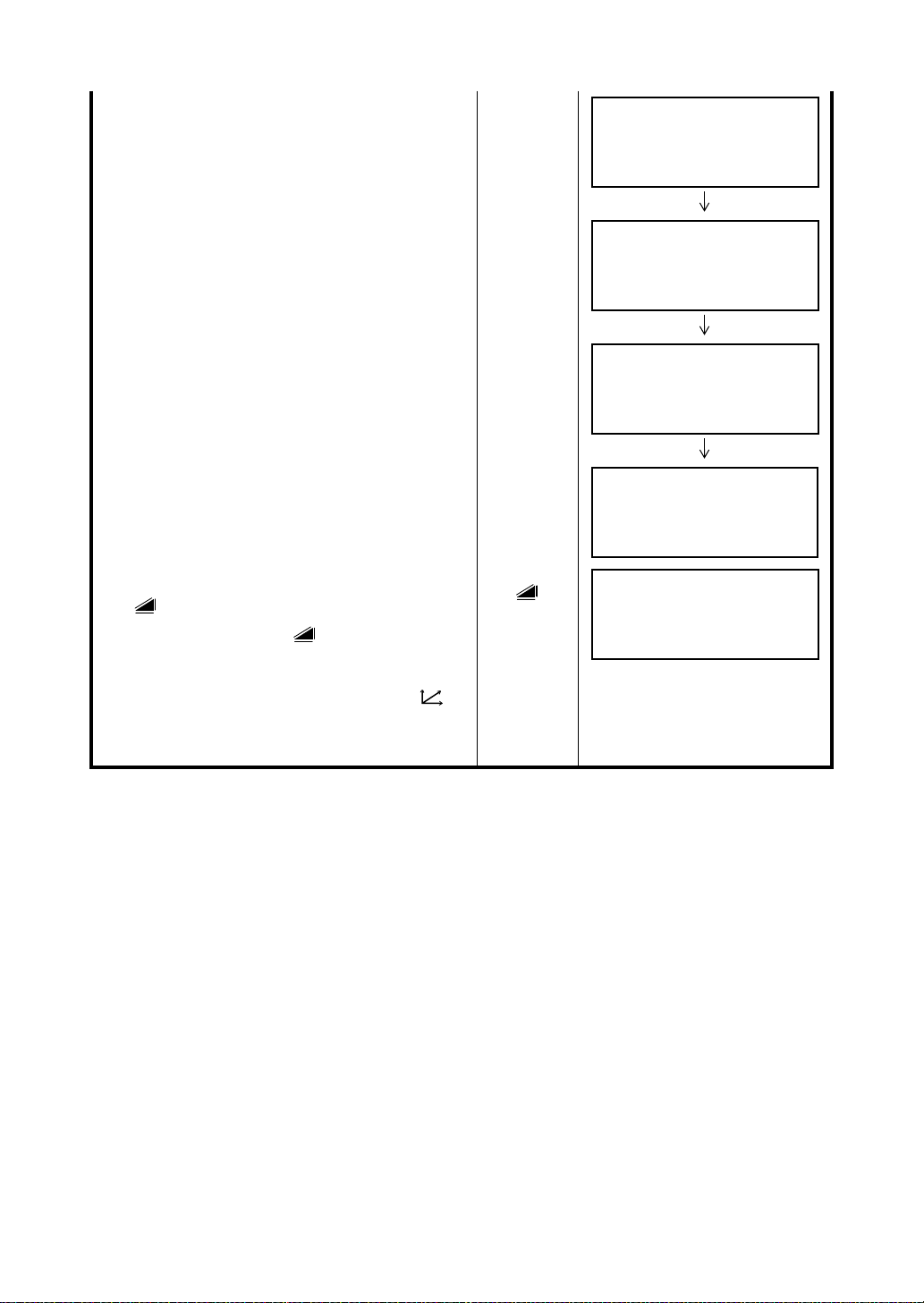
4 DISTANCE MEASUREMENT
6 Collimate the center of the column (P1) and press
the [F1](MEAS) key.
N-time measuring will start.
After the measurement, angle measuring display
of the left side (P2) will be shown.
7 Collimate the left side of the column (P2) and
press the [F4](SET) key.
After the measurement, angle measuring display
of the right side (P3) will be shown.
8 Collimate the right side of the column (P3) and
press the [F4](SET) key.
The distance between the instrument and center
of the column (P0) will be calculated.
9 To show the relative elevation (VD), press the
[] key.
Each time pressing the [ ] key, horizontal
distance, relative elevation and slope distance are
shown in sequence.
● To show coordinate of point P0, press the [ ]
key .
10 To escape the measuring, press the [ESC] key.
The display returns to the previous mode.
Collimate
P1
[F1]
Collimate
P2
[F4]
Collimate
P3
[F4]
[]
COLUMN OFFSET
Center
HD* [n] << m
>Measuring...
COLUMN OFFSET
Left
HR: 120°30'40"
--- --- --- SET
COLUMN OFFSET
Right
HR: 180°30'40"
--- --- --- SET
COLUMN OFFSET
HR: 150°30'40"
HD: 43.321 m
NEXT --- --- ---
COLUMN OFFSET
HR: 150°30'40"
VD: 2.321 m
NEXT --- --- ---
N
P
N
P
N
P
N
P
N
P
4-14
Page 47
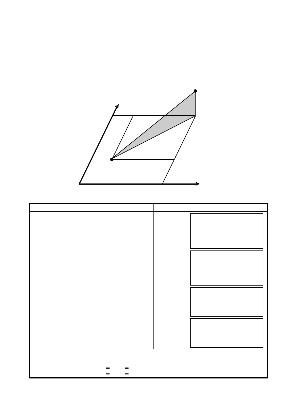
5 COORDINATE MEASUREMENT
5 COORDINATE MEASUREMENT
5.1 Setting Coordinate Values of Occupied Point
Set the coordinates of the instrument (occupied point) according to coordinate origin, and the
instrument automatically converts and displays the unknown point (prism point) coordinates following
the origin.
It is possible to retain the coordinates of the occupied point after turning the power off.
Refer to Chapter 16 “SELECTING MODE”.
N
n
Inst.PointC
Origin(0,0,0)
e
Prism (n,e,z)
z
E
Operating procedure Operation Display
1 Press the [F4](
measurement mode to get the function on page 2.
2 Press the [F3](OCC) key.
3 Enter N coordinate value. *1)
↓
) key from the coordinate
[F4]
[F3]
[F1]
Enter data
[F4]
4 Enter E and Z coordinate values in the same
manner.
After entering the values, the display returns
coordinate measuring display.
*1) Refer to Section 2.6 “How to Enter Alphanumeric characters”.
● Input range –99999999.9990 N,E,Z +99999999.9990 m
–99999999.999 N,E,Z +99999999.999 ft.
–99999999.11.7 N,E,Z +99999999.11.7 ft.+inch
< <
< <
< <
N: 123.456 m
E: 34.567 m
Z: 78.912 m
MEAS MODE NP/P P1
R.HT INSHT OCC P2
N→ 0.000 m
E: 0.000 m
Z: 0.000 m
INPUT --- --- ENTER
1234 5678 90. –[ENT]
N: -72.000 m
E→ 0.000 m
Z: 0.000 m
INPUT --- --- ENTER
N: 51.456 m
E: 34.567 m
Z: 78.912 m
MEAS MODE NP/P P1
↓
↓
↓
5-1
Page 48

5 COORDINATE MEASUREMENT
5.2 Setting Height of the Instrument
It is possible to retain the height of instrument after turning the power off. Refer to Chapter 16
“SELECTING MODE”.
Operating procedure Operation Display
1 Press the [F4](
measurement mode to get the function on page 2.
2 Press the [F2](INSHT) key.
The current value is displayed.
3 Enter the instrument height. *1)
↓
) key from the coordinate
[F4]
[F2]
[F1]
Enter Inst.HT
[F4]
N: 123.456 m
E: 34.567 m
Z: 78.912 m
MEAS MODE NP/P P1
R.HT INSHT OCC P2
INSTRUMENT HEIGHT
INPUT
INS.HT: 0.000 m
INPUT ––– ––– ENTER
1234 5678 90. –[ENT]
N: 123.456 m
E: 34.567 m
Z: 78.912 m
MEAS MODE NP/P P1
↓
↓
↓
*1) Refer to Section 2.6 “How to Enter Alphanumeric characters”.
● Input range –999.9999 Instrument height +999.9999 m
–999.999 Instrument height +999.999 ft.
–999.11.7 Instrument height +999.11.7 ft.+inch
< <
< <
< <
5.3 Setting Height of Target (Prism Height)
This mode can be used to obtain Z coordinate values . It is possible to retain the height of target after
turning the power off. Refer to Chapter 16 “SELECTING MODE”.
Operating procedure Operation Display
1 Press the [F4](
measurement mode to get the function on page 2.
2 Press the [F1](R.HT) key.
The current value is displayed.
3 Enter the prism height. *1)
↓
) key from the coordinate
[F4]
[F1]
[F1]
Enter R. HT
[F4]
N: 123.456 m
E: 34.567 m
Z: 78.912 m
MEAS MODE NP/P P1
R.HT INSHT OCC P2
REFLECTOR HEIGHT
INPUT
R.HT: 0.000 m
INPUT ––– ––– ENTER
1234 5678 90. –[ENT]
N: 123.456 m
E: 34.567 m
Z: 78.912 m
MEAS MODE NP/P P1
↓
↓
↓
*1) Refer to Section 2.6 “How to Enter Alphanumeric characters”.
● Input range –999.9999 Prism height +999.9999 m
–999.999 Prism height +999.999 ft.
–999.11.7 Prism height +999.11.7 ft.+inch
< <
< <
< <
5-2
Page 49

5 COORDINATE MEASUREMENT
5.4 Execution of Coordinate Measuring
Measure the coordinates by entering the instrument height and prism height, coordinates of unknown
point will be measured directly.
● When setting coordinate values of occupied point, see Section 5.1 “Setting Coordinate Values of
Occupied Point”
● When setting the instrument height and prism height, see Section 5.2 “Setting Height of the
Instrument” and 5.3 “Setting Height of Target (Prism Height)”.
● The coordinates of the unknown point are calculated as shown below and displayed:
Coordinates of occupied point : (N
Instrument height : INS.HT
Prism height : R.HT
Vertical distance (Relative elevation) : z (VD)
Coordinates of the center of the prism,
originated from the center point of the instrument : (n,e,z)
Coordinates of unknown point : (N
N
+n
1=N0
E
+e
1=E0
Z
+INS.HT+z - R.HT
1=Z0
1,E1,Z1
)
Coordinates of the center of the prism, originated from the
center point of the instrument (n, e, z)
0,E0,Z0
)
Center point of the instrument
(No, Eo, Zo+INS.HT)
INS.HT
SD
Occupied point (No, Eo, Zo)
Origin (o, o, o)
Operating procedure Operation Display
HD
1 Set the direction angle of known point A. *1)
2 Collimate target prism.
3 Press the [ ] key.
Measuring starts.
The result will be shown.
Unknown point
(N
1, E1, Z1)
Set direction
Collimate P
angle
[]
R.HT
z(VD)
V : 90°10'20"
HR: 120°30'40"
0SET HOLD HSET P1
N*[r] << m
E: m
Z: m
MEAS MODE NP/P P1
N* 123.456 m
E: 34.567 m
Z: 78.912 m
MEAS MODE NP/P P1
↓
↓
↓
*1) Refer to Section 3.3 “Measuring from the Required Horizontal Angle”.
● In case the coordinate of instrument point is not entered, (0,0,0) will be used as the default for the
instrument point.
The instrument height will be calculated as 0 when the instrument height is not entered.
● The prism height will be calculated as 0 when the prism height is not set.
5-3
Page 50
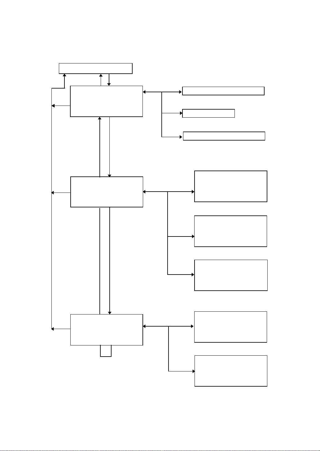
6 SPECIAL MODE (Menu Mode)
By pressing the [MENU] key, the instrument will be in MENU mode.
In this mode, special measuring , setting and adjustment are possible.
Normal measurement mode
[ESC]
MENU 1/3
F1:DATA COLLECT
[ESC]
F2:LAYOUT
F3:MEMORY MGR. P
MENU 2/3
[ESC]
F1:PROGRAMS
F2:GRID FACTOR
F3:ILLUMINATION P
[MENU]
[F4]
[F4]
[ESC]
[F1]
[ESC]
[F2]
[F3]
[F1]
[F2]
↓
↓
6 SPECIAL MODE (Menu Mode)
"DATA COLLECTION MODE"
See Chapter 7 “DATA COLLECTION”.
"LAYOUT MODE"
See Chapter 8 “LAYOUT”.
"MEMORY MANAGER MODE"
See Chapter 9 “MEMORY MANAGER
MODE”.
Programs
PROGRAMS 1/2
F1:REM
F2:MLM
F3:Z COORD. P
Grid factor
↓
GRID FACTOR
=1.000000
>MODIFY? [YES][NO]
MENU 3/3
[ESC]
F1:PARAMETERS 1
F2:CONTRAST ADJ.
P
[F4]
Reticle illumination
ILLUMINATION[ON:1]
[F3]
F1:ON
F2:OFF
F3:LEVEL
Setting mode 1
PARAMETERS 1 1/2
[ESC]
[F1]
F1:MINIMUM READING
F2:AUTO POWER OFF
↓
F3:TILT P
Display contrast adjustment
↓
CONTRAST ADJUSTMENT
[F2]
LEVEL:4
↓
↑ --- ENTER
6-1
Page 51
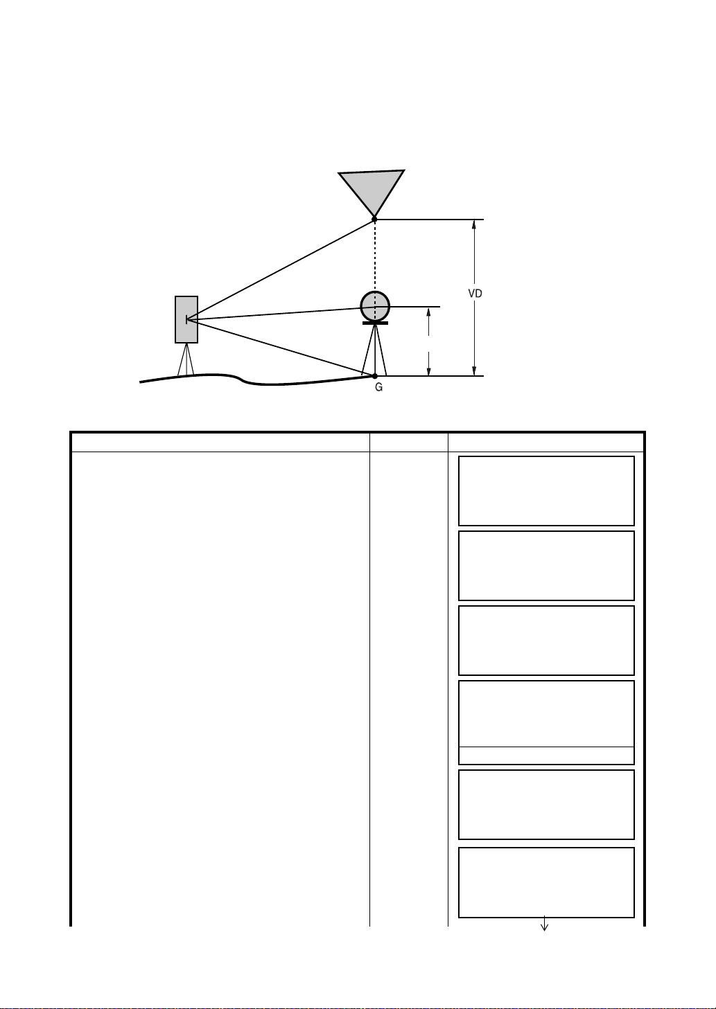
6 SPECIAL MODE (Menu Mode)
6.1 Application Measurement (PROGRAMS)
6.1.1 Remote Elevation measurement (REM)
To obtain elevation of the point at which setting the target prism is not possible, place the prism at any
point on the vertical line from the target then carry out REM procedure as follows.
Target K
Prism
Instrument
1) With prism height (h) input (Example :h=1.5m)
Operating procedure Operation Display
1 After pressing the [MENU] key, press the [F4](P
key to get the menu on page 2.
2 Press the [F1] key.
3 Press the [F1](REM) key.
4 Press the [F1] key.
5 Enter prism height. *1)
6 Collimate prism.
7 Press the [F1](MEAS) key.
Measuring starts.
↓
)
Prism height
[MENU]
[F4]
[F1]
[F1]
[F1]
[F1]
Enter R.HT
[F4]
Collimate P
[F1]
MENU 2/3
F1:PROGRAMS
F2:GRID FACTOR
F3:ILLUMINATION P
PROGRAMS 1/2
F1:REM
F2:MLM
F3:Z COORD. P
REM
F1:INPUT R.HT
F2:NO R.HT
REM-1
<STEP-1>
R.HT : 0.000 m
INPUT ––– ––– ENTER
1234 5678 90. –[ENT]
REM-1
<STEP-2>
HD: m
MEAS ––– NP/P –––
REM-1
<STEP-2>
HD*[n] << m
>Measuring...
↓
↓
6-2
Page 52
6 SPECIAL MODE (Menu Mode)
Horizontal distance (HD) between the instrument
and prism will be shown.
8 Collimate target K.
Vertical distance (VD) will be shown. *2),3)
*1) Refer to Section 2.6 “How to Enter Alphanumeric characters”.
*2) To return to procedure
To return to procedure
*3) To return to PROGRAMS Menu, press the [ESC] key.
2) Without prism height input
Operating procedure Operation Display
5, press the [F2](R.HT) key.
6, press the [F3](HD) key.
1 After pressing the [MENU] key, press the [F4](P
key to get the menu on page 2.
2 Press the [F1] key.
3 Press the [F1](REM) key.
↓
)
Collimate K
[MENU]
[F4]
[F1]
[F1]
REM-1
<STEP-2>
HD* 123.456 m
>Measuring...
REM-1
VD: 1.500 m
––– R.HT HD –––
REM-1
VD: 10.456 m
––– R.HT HD –––
MENU 2/3
F1:PROGRAMS
F2:GRID FACTOR
F3:ILLUMINATION P
PROGRAMS 1/2
F1:REM
F2:MLM
F3:Z COORD. P
REM
F1:INPUT R.HT
F2:NO R.HT
↓
↓
4 Press the [F2] key.
5 Collimate prism.
6 Press the [F1](MEAS) key.
Measuring starts.
Horizontal distance (HD) between the instrument
and prism will be shown.
6-3
[F2]
Collimate P
[F1]
REM-2
<STEP-1>
HD: m
MEAS ––– NP/P –––
REM-2
<STEP-1>
HD* [n] << m
>Measuring...
REM-2
<STEP-1>
HD* 123.456 m
>Measuring...
Page 53

6 SPECIAL MODE (Menu Mode)
The prism position will be decided.
7 Collimate ground point G.
8 Press the [F4](SET) key.
The position of point G will be decided. *1)
9 Collimate target K.
Vertical distance (VD) will be shown. *2)
*1) To return to procedure
To return to procedure
*2) To return to PROGRAMS Menu, press the [ESC] key.
5, press the [F3](HD) key.
7, press the [F2](V) key.
Collimate G
[F4]
Collimate K
REM-2
<STEP-2>
V : 60°45'50"
––– ––– ––– SET
REM-2
<STEP-2>
V : 123°45'50"
––– ––– ––– SET
REM-2
VD: 0.000 m
––– V HD –––
REM-2
VD: 10.456 m
––– V HD –––
6-4
Page 54

6 SPECIAL MODE (Menu Mode)
6.1.2 Missing Line Measurement (MLM)
Measurement for horizontal distance (dHD), slope distance (dSD), elevation (dVD) and horizontal
bearing (HR) between two target prisms.
It is possible to enter the coordinate value directly or calculate from coordinate data file.
MLM mode has two modes.
1: MLM-1 (A-B, A-C) :Measurement is A-B, A-C, A-D,......
2: MLM-2 (A-B, B-C) :Measurement is A-B, B-C, C-D,......
Prism A
Prism B
Instrument
Instrument
● It is necessary to set the direction angle of the instrument.
[Example] MLM-1 (A-B, A-C)
● Procedure of MLM-2 (A-B, B-C) mode is completely same as MLM-1 mode
Operating procedure Operation Display
1 After pressing the [MENU] key, press the [F4](P
key to get the menu on page 2.
2 Press the [F1] key.
3 Press the [F2](MLM) key.
Prism A
↓
)
[MENU]
[F4]
[F1]
[F2]
Prism C
Prism B
MENU 2/3
F1:PROGRAMS
F2:GRID FACTOR
F3:ILLUMINATION P
PROGRAMS 1/2
F1:REM
F2:MLM
F3:Z COORD. P
MLM
F1:USE FILE
F2:DON’T USE
↓
↓
4 Press the [F1] or [F2] key to select using
coordinate file.
[Example:F2 : DON’T USE]
6-5
[F2]
GRID FACTOR
F1:USE G.F.
F2:DON’T USE
Page 55

6 SPECIAL MODE (Menu Mode)
5 Press the [F1] or [F2] key to select using
GRID FACTOR.
[Example:F2 : DON’T USE]
6 Press the [F1] key.
7 Collimate prism A, and press the [F1](MEAS) key.
Horizontal distance (HD) between the instrument
and prism A will be shown.
The prism position will be decided.
8 Collimate prism B and press the [F1](MEAS) key.
Horizontal distance (HD) between the instrument
and prism B will be shown.
[F2]
[F1]
Collimate A
[F1]
Collimate B
[F1]
MLM
F1:MLM-1(A-B, A-C)
F2:MLM-2(A-B, B-C)
MLM-1(A-B, A-C)
<STEP-1>
HD: m
MEAS R.HT NEZ NP/P
MLM-1(A-B, A-C)
<STEP-1>
HD*[n] << m
MEAS R.HT NEZ NP/P
MLM-1(A-B, A-C)
<STEP-1>
HD* 123.456 m
MEAS R.HT NEZ NP/P
MLM-1(A-B, A-C)
<STEP-2>
HD: m
MEAS R.HT NEZ NP/P
MLM-1(A-B, A-C)
<STEP-2>
HD*[n] << m
MEAS R.HT NEZ NP/P
The horizontal distance (dHD) and relative
elevation (dVD) between prism A and B.
9 To show slope distance (dSD) , press [ ] key.
10 To measure the distance between points A and C,
press the [F3](HD). *1)
11 Collimate point C (Prism C) and press the
[F1](MEAS) key.
Horizontal distance (HD) between the instrument
and prism C will be shown.
[]
[F3]
Collimate
prism C
[F1]
MLM-1(A-B, A-C)
<STEP-2>
HD* 345.678 m
MEAS R.HT NEZ NP/P
MLM-1(A-B, A-C)
dHD : 123.456 m
dVD : 12.345 m
––– ––– HD –––
MLM-1(A-B, A-C)
dSD : 234.567 m
HR : 12°34'40"
––– ––– HD –––
MLM-1(A-B, A-C)
<STEP-2>
HD: m
MEAS R.HT NEZ NP/P
6-6
Page 56
6 SPECIAL MODE (Menu Mode)
The horizontal distance (dHD) and relative
elevation (dVD) between prism A and C.
MLM-1(A-B, A-C)
dHD : 234.567 m
dVD : 23.456 m
––– ––– HD –––
12 To measure the distance between points A and D,
repeat procedure 12 to14. *1)
*1) To return to previous mode, press the [ESC] key.
● How to use coordinate data
It is possible to input coordinate value directly or calculate from coordinate data file
Operating procedure Operation Display
To use coordinate data file, select “USE FILE”
in step
4.
After procedure
6.
MLM-1(A-B, A-C)
<STEP-1>
HD: m
MEAS R.HT NEZ NP/P
1 Press the [F3](NEZ) key.
Direct key input display will be shown.
[F3]
N> 0.000 m
E: 0.000 m
Z: 0.000 m
INPUT ––– PT# ENTER
2 Press the [F3](PT#) key to use coordinate data
file.
Point number input display will be shown.
Pressing the [F3](HD) key, the display will return
to procedure
6.
[F3]
MLM-1(A-B,A-C)
PT#:__________
INPUT LIST HD ENTER
After selecting coordinate input mode by pressing
the [F3](NEZ or PT# or HD) key, press the
[F1](INPUT) key and enter the data.
6-7
Page 57

6 SPECIAL MODE (Menu Mode)
6.1.3 Setting Z Coordinate of Occupied Point
Occupied point coordinate data and known point actual measuring data are utilized, z coordinate of
occupied point is calculated and reset again.
Known point data and coordinate data can use the coordinate data file.
1) Setting occupied coordinate
[Example setting] Using coordinate data file.
Operating procedure Operation Display
1 After pressing [MENU] key, press [F4](P
get the menu on page 2.
↓
) key to
[MENU]
[F4]
MENU 2/3
F1:PROGRAMS
F2:GRID FACTOR
F3:ILLUMINATION P
2 Press the [F1] key.
[F1]
PROGRAMS 1/2
F1:REM
F2:MLM
F3:Z COORD. P
3 Press the [F3](Z COORD.) key.
[F3]
Z COORD.SETTING
F1:USE FILE
F2:DON’T USE
↓
↓
4 Press the [F1](USE FILE) key.
5 Press the [F1](INPUT) key and enter the File
Name.
6 Press the [F1] key.
7 Press the [F1](INPUT) key and enter the Point
number. Instrument height setting display will be
shown.
8 Press the [F1](INPUT) key and enter the height.
The display returns to Z coordinate menu.
[F1]
[F1]
Enter FN
[F4]
[F1]
[F1]
Enter PT#
[F4]
[F1]
Enter HT
[F4]
SELECT A FILE
FN:_________
INPUT LIST ––– ENTER
Z COORD.SETTING
F1:OCC.PT INPUT
F2:REF.MEAS
OCC.PT
PT#:_________
INPUT LIST NEZ ENTER
INSTRUMENT HEIGHT
INPUT
INS.HT: 0.000 m
INPUT ––– ––– ENTER
Z COORD.SETTING
F1:OCC.PT INPUT
F2:REF.MEAS
● For more information about data file, see Chapter 9 “MEMORY MANAGER MODE” .
6-8
Page 58

6 SPECIAL MODE (Menu Mode)
2) Z Coordinate Calculation from Known Point Measuring Data
[Example setting] Using coordinate data file
Operating procedure Operation Display
1 After pressing [MENU] key, press [F4](P
get the menu on page 2.
↓
) key to
[MENU]
[F4]
MENU 2/3
F1:PROGRAMS
F2:GRID FACTOR
F3:ILLUMINATION P
2 Press the [F1] key.
[F1]
PROGRAMS 1/2
F1:REM
F2:MLM
F3:Z COORD. P
3 Press the [F3](Z COORD.) key.
[F3]
Z COORD.SETTING
F1:USE FILE
F2:DON’T USE
↓
↓
4 Press the [F1](USE FILE) key.
5 Press the [F1](INPUT) key and enter the File
Name.
6 Press the [F2] key.
7 Press the [F1](INPUT) key and enter the Point
Number in coordinate data file.
8 Press the [F3](YES) key and enter the Point
Number in coordinate data file.
9 Press the [F1](INPUT) key and enter the height.
10 Collimate a prism on the point and press the
[F1](MEAS) key.
Measuring starts. *1)
[F1]
[F1]
Enter FN
[F4]
[F2]
[F1]
Enter PT#
[F4]
[F3]
[F1]
Enter R. HT
[F4]
Collimate P
[F1]
SELECT A FILE
FN:_________
INPUT LIST ––– ENTER
Z COORD.SETTING
F1:OCC.PT INPUT
F2:REF.MEAS
NOO1#
PT#:_________
INPUT LIST NEZ ENTER
N: 4.356 m
E: 16.283 m
Z: 1.553 m
>OK ? [YES][NO]
REFLECTOR HEIGHT
INPUT
R.HT: 0.000 m
INPUT ––– ––– ENTER
REFLECTOR HEIGHT
INPUT
R.HT: 0.000 m
MEAS ––– NP/P –––
HR: 120°30'40"
HD*[n] << m
VD: m
>Measuring...
6-9
Page 59

11 Press the [F4](CALC) key.*2)
Z : Z coordinate
dZ: Standard deviation
12 Press the [F4](SET) key. *3)
Z coordinate of the occupied point will be set.
Bascksight point measuring screen will be shown.
13 Press the [F3](YES) key.
Horizontal angle will be set.
The display returns to Programs 1/2 menu.
*1) Measurement is Fine N-times measurement mode.
*2) To measure other points, press the [F1](NEXT) key.
*3) Pressing the [F3] key, the display will be changed alternately.
[F4]
[F4]
[F3]
6 SPECIAL MODE (Menu Mode)
HR: 120°30'40"
HD: 12.345 m
VD: 23.456 m
NEXT ––– ––– CALC
Z COORD. SETTING
Z : 1.234 m
dZ : 0.002 m
––– ––– BS SET
BACKSIGHT
HR: 23°20'40"
>OK? [YES][NO]
PROGRAMS 1/2
F1:REM
F2:MLM
F3:Z COORD. P
↓
6-10
Page 60
6 SPECIAL MODE (Menu Mode)
6.1.4 Area Calculation
This mode calculate the area of a closed figure.
There are two area calculation methods as follows.
1) Area Calculation from Coordinate data file
2) Area Calculation from Measured data
● Area is not calculated correctly if enclosed lines cross each other.
● It is impossible to calculate what a mix of coordinate file data and measured data.
● If the coordinate data file does not exist, the area calculation from measured data is done
automatically.
● The numbers of points used to calculate are not limited.
1) Area Calculation from Coordinate Data File
Operating procedure Operation Display
1 After pressing the [MENU] key, press the [F4](P
key to get the menu on page 2/3.
↓
)
[MENU]
[F4]
MENU 2/3
F1:PROGRAMS
F2:GRID FACTOR
F3:ILLUMINATION P
2 Press the [F1] key.
[F1]
PROGRAMS 1/2
F1:REM
F2:MLM
F3:Z COORD. P
3 Press the [F4](P
menu on page 2/2.
↓
) key to get the PROGRAMS
[F4]
PROGRAMS 2/2
F1:AREA
F2:POINT TO LINE
P
4 Press the [F1](AREA) key.
[F1]
AREA
F1:FILE DATA
F2:MEASUREMENT
↓
↓
↓
5 Press the [F1](FILE DATA) key.
6 Press the [F1](INPUT) key and enter the File
Name.
Initial display will be shown.
7 Press the [F4](NEXT) key. *1),2)
The top of the file data (DATA-01) will be set and
the second point number will be shown.
8 Repeat pressing the [F4](NEXT) key to set
required number of points.
6-11
[F1]
[F1]
Enter FN
[F4]
[F4]
[F4]
SELECT A FILE
FN:_________
INPUT LIST ––– ENTER
AREA 0000
m.sq
NEXT# :DATA-01
PT# LIST UNIT NEXT
AREA 0001
m.sq
NEXT# :DATA-02
PT# LIST UNIT NEXT
Page 61
6 SPECIAL MODE (Menu Mode)
When 3 or more points are set, the area
surrounded by the points is calculated and the
result will be shown.
AREA 0021
123.456 m.sq
NEXT# :DATA-22
PT# LIST UNIT NEXT
*1) To set specify point, press the [F1](PT#) key.
*2) To show the list of the coordinate data in the file, press the [F2](LIST) key.
2) Area Calculation from Measured Data
Operating procedure Operation Display
1 After pressing the [MENU] key, press the [F4](P
key to get the menu on page 2/3.
↓
)
[MENU]
[F4]
MENU 2/3
F1:PROGRAMS
F2:GRID FACTOR
F3:ILLUMINATION P
2 Press the [F1] key.
[F1]
PROGRAMS 1/2
F1:REM
F2:MLM
F3:Z COORD. P
3 Press the [F4](P
menu on page 2/2.
↓
) key to get the PROGRAMS
[F4]
PROGRAMS 2/2
F1:AREA
F2:POINT TO LINE
P
4 Press the [F1](AREA) key.
[F1]
AREA
F1:FILE DATA
F2:MEASUREMENT
↓
↓
↓
5 Press the [F2](MEASUREMENT) key.
6 Press the [F1] or [F2] key to select using GRID
FACTOR.
[Example:F2 : DON’T USE]
7 Collimate a prism and press the [F1](MEAS) key.
Measuring starts. *1)
8 Collimate next point and press the [F1](MEAS)
key .
[F2]
[F2]
Collimate P
[F1]
Collimate
[F1]
AREA
F1:USE G.F.
F2:DON’T USE
AREA 0000
m.sq
MEAS ––– UNIT NP/P
N*[n] <<< m
E: m
Z: m
>Measuring...
AREA 0001
m.sq
MEAS ––– UNIT NP/P
6-12
Page 62

6 SPECIAL MODE (Menu Mode)
When 3 or more points are measured, the area
surrounded by the points is calculated and the
result will be shown.
*1) Measurement is Fine N-times measurement mode.
● To change the display unit
It is possible to change the displayed area unit.
Operating procedure Operation Display
1 Press the [F3](UNIT) key.
2 Select a unit by pressing the [F1] to [F4] key.
Example: [F2](ha) key.
[F3]
[F2]
AREA 0003
234.567 m.sq
MEAS ––– UNIT NP/P
AREA 0003
100.000 m.sq
MEAS ––– UNIT NP/P
AREA 0003
100.000 m.sq
m.sq ha ft.sq acre
AREA 0003
0.010 ha
MEAS ––– UNIT NP/P
● m.sq : square meter ha : hectare ft.sq : square feet acre : acre.
6-13
Page 63

6 SPECIAL MODE (Menu Mode)
6.1.5 Point to Line Measurement
This mode is used to obtain the coordinate data with the origin point A(0,0,0) and the line AB as N
axis.
Place the 2 prisms at the points A and B on the line, and place the instrument at unknown point C. After
measuring the 2 prisms , the coordinate data and the direction angle of the instrument will be calculated
and restored.
P(n, e, z)
Prism P1
R.HT
INS.HT
Operating procedure Operation Display
Instrument Point (Unknown point)
1 After pressing the [MENU] key, press the [F4](P
key to get the menu on page 2/3.
2 Press the [F1] key.
3 Press the [F4](P
menu on page 2/2.
↓
) key to get the PROGRAMS
4 Press the [F2] key.
5 Press the [F1](INPUT) key and enter instrument
height.
6 Press the [F1](INPUT) key and enter reflector
A(P1) height.
↓
)
Prism P2
Line
[MENU]
[F4]
[F1]
[F4]
[F2]
[F1]
Enter
INS.HT
[F4]
[F1]
Enter R.HT
[F4]
MENU 2/3
F1:PROGRAMS
F2:GRID FACTOR
F3:ILLUMINATION P
PROGRAMS 1/2
F1:REM
F2:MLM
F3:Z COORD. P
PROGRAMS 2/2
F1:AREA
F2:POINT TO LINE
P
INSTRUMENT HEIGHT
INPUT
INS.HT: 0.000 m
INPUT ––– ––– ENTER
REFLECTOR HEIGHT
INPUT
R.HT: 0.000 m
INPUT ––– ––– ENTER
POINT TO LINE
MEAS.P1
HD: m
MEAS ––– NP/P –––
↓
↓
↓
6-14
Page 64

6 SPECIAL MODE (Menu Mode)
Collimate prism P1 (Origin) and press [F1](MEAS)
7
key .
Measuring starts. *1)
Input display of reflector B(P2) height will be
shown.
8 Press [F1](INPUT) key and enter reflector B(P2)
height.
9 Collimate prism B (P2)(Origin) and press the
[F1](MEAS) key.
Measuring starts. *1)
The coordinate data and the direction angle of the
instrument are calculated and restored.
The result (The distance between A and B) will be
displayed.
dHD: Horizontal distance
dVD:Vertical distance
dSD:Slope distance *2) ,3)
10 Press [F1](NEZ) key to measure other points.
11 Collimate a prism and press [F1](MEAS) key.
Coordinate measurement starts. *4)
The result will be shown. *5)
Collimate
P1
[F1]
[F1]
Enter R. HT
[F4]
Collimate
P2
[F1]
[F1]
Collimate P
[F1]
POINT TO LINE
MEAS.P1
HD*[n] << m
>Measuring...
REFLECTOR HEIGHT
INPUT
R.HT: 0.000 m
INPUT ––– ––– ENTER
POINT TO LINE
MEAS.P2
HD: m
MEAS ––– NP/P –––
POINT TO LINE
MEAS.P2
HD*[n] << m
>Measuring...
DIST. (P1-P2) 1/2
dHD: 10.000 m
dVD: 0.000 m
NEZ S.CO ––– P
N: 0.000 m
E: 0.000 m
Z: 0.000 m
MEAS R.HT NP/P –––
>Measuring...
N: 3.456 m
E: 5.432 m
Z: 0.000 m
MEAS R.HT NP/P –––
↓
*1) Measurement is Fine N-times measurement mode.
*2) To show dSD, press [F4](P
*3) To show the new occupied data, press [F2](S.CO) key.
*4) Measurement is Fine N-times measurement mode.
*5) To return to previous mode, press the [ESC] key.
↓
) key.
6-15
Page 65
6.2 Setting the GRID FACTOR
GRID FACTOR can reset in this menu mode.
For more information, refer to Section 8.1.1”Setting the GRID FACTOR”
Operating procedure Operation Display
1 After pressing the [MENU] key, press the [F4](P
key to get the menu on page 2.
2 Press the [F2](GRID FACTOR) key.
↓
)
[MENU]
[F4]
[F2]
6 SPECIAL MODE (Menu Mode)
MENU 2/3
F1:PROGRAMS
F2:GRID FACTOR
F3:ILLUMINATION P
↓
GRID FACTOR
=0.998843
>MODIFY? [YES][NO]
3 Press the [F3](YES) key.
[F3]
GRID FACTOR
ELEV.→1000 m
SCALE:0.999000
INPUT ––– ––– ENTER
4 Press the [F1] (INPUT) key and enter Elevation.
*1) Press the [F4](ENT) key.
5 Enter Scale Factor in the same way.
[F1]
Enter ELEV.
[F4]
[F1]
Enter Scale
[F4]
1234 5678 90. –[ENT]
GRID FACTOR
ELEV.:2000 m
SCALE→1.001000
INPUT ––– ––– ENTER
Grid Factor is displayed for 1 to 2 second and
display returns to menu.
*1) Refer to Section 2.6 “How to Enter Alphanumeric characters”.
● Input Range :Elevation : –9,999 to +9,999 meter (–32,805 to +3,2805 ft, ft+in)
Scale Factor: 0.990000 to 1.010000
GRID FACTOR
=1.000686
6-16
Page 66

6 SPECIAL MODE (Menu Mode)
6.3 Setting Illumination of Display and Cross Hairs
Setting ON/OFF/LEVEL (1 to 9) for illumination of display (LCD) and reticle.
Setting LEVEL (1 to 9) is only for reticle.
[Example setting] LEVEL:2 and turn on the illumination.
Operating procedure Operation Display
1 After pressing the [MENU] key, press the [F4](P
key to get the menu on page 2.
2 Press the [F3] key.
The data previously set is shown.
3 Press the [F3](LEVEL) key.
4 Press the [F2](↑) key, and then press the
[F4](ENTER) key.
5 Press the [F1](ON) key.
↓
)
[MENU]
[F4]
[F3]
[F3]
[F2]
[F4]
[F1]
MENU 2/3
F1:PROGRAMS
F2:GRID FACTOR
F3:ILLUMINATION P
ILLUMINATION [OFF:1]
F1:ON
F2:OFF
F3:LEVEL
ILLUMINATION [OFF:1]
[LEVEL MODE]
↓
ILLUMINATION [OFF:2]
F1:ON
F2:OFF
F3:LEVEL
ILLUMINATION [ON:2]
F1:ON
F2:OFF
F3:LEVEL
↓
↑ ––– ENTER
● To return to previous mode, press the [ESC] key.
6-17
Page 67

6 SPECIAL MODE (Menu Mode)
6.4 Setting Mode 1
In this mode, the following settings are possible.
1. Setting Minimum Reading
2. Auto Power off
3. Vertical and Horizontal Angle Tilt Correction (Tilt ON/OFF)
(GPT-2009 has vertical angle tilt correction only.).
4. Systematic Error of Instrument Correction (GPT-2003/2005/2006)
5. Selecting battery type
● This setting is memorized after power off.
6.4.1 Setting Minimum Reading
Select minimum display unit for angle measurement, coarse distance measurement mode.
● To select minimum display for fine measurement mode, see Chapter 16 “SELECTING MODE” .
Models
GPT-2003
GPT-2005
GPT-2006
GPT-2009 10" / 5" 2mgon / 1mgon 0.1mil / 0.01mil
[Example] Minimum angle : 5”, Coarse : 1mm
Operating procedure Operation Display
Degree GON MIL
5" / 1" 1mgon / 0.2mgon 0.1mil / 0.01mil
1 After pressing the [MENU] key, press the [F4](P
key twice to get the menu on page 3.
2 Press the [F1] key.
3 Press the [F1] key.
Angle Unit
↓
)
[MENU]
[F4]
[F4]
[F1]
[F1]
Coarse mode
Distance unit
10mm (0.02ft)/
1mm(0.005ft)
MENU 3/3
F1:PARAMETERS 1
F2:CONTRAST ADJ.
P
PARAMETERS 1
F1:MINIMUM READING
F2:AUTO POWER OFF
F3:TILT P
MINIMUM READING
F1:ANGLE
F2:COARSE
↓
↓
4 Press the [F1] key.
5 Press the [F2](5") key and press the [F4](ENTER)
key .
6 Press the [F2] key.
6-18
[F1]
[F2]
[F4]
[F2]
MINIMUM ANGLE
[F1: 1" ]
F2: 5"
ENTER
MINIMUM READING
F1:ANGLE
F2:COARSE
COARSE READING
F1: 1mm
[F2:10mm]
ENTER
Page 68

6 SPECIAL MODE (Menu Mode)
7 Press the [F1] key and press the [F4](ENTER) key.
[F1]
[F4]
MINIMUM READING
F1:ANGLE
F2:COARSE
● To return to previous mode, press the [ESC] key.
6.4.2 Auto Power Off
If no key operation is given or no process of measurement is performed for more than 30 minutes ( No
change exceeding 30” has occurred during horizontal angle or vertical angle measurement.), the power
turns off automatically. If the instrument is set at distance measurement mode ( No change in distance
exceeding 10cm has occurred during distance measurement), the mode changes to angle
measurement automatically in case that the instrument does not operate for approximately 10 minutes,
and the power turns off after 20 minutes.
Operating procedure Operation Display
1 After pressing the [MENU] key, press the [F4](P
key twice to get the menu on page 3.
↓
)
[MENU]
[F4]
[F4]
MENU 3/3
F1:PARAMETERS 1
F2:CONTRAST ADJ.
P
2 Press the [F1] key.
[F1]
PARAMETERS 1 1/2
F1:MINIMUM READING
F2:AUTO POWER OFF
F3:TILT P
3 Press the [F2] key.
The data previously set is shown.
[F2]
AUTO POWER OFF [OFF]
F1:ON
F2:OFF
ENTER
↓
↓
4 Press the [F1](ON) key or [F2](OFF) key, and
press the [F4](ENTER) key.
[F1] or [F2]
[F4]
6-19
Page 69

6 SPECIAL MODE (Menu Mode)
6.4.3 Vertical and Horizontal Angle Tilt correction ( Tilt ON/OFF)
(GPT-2009 has vertical angle tilt correction only.)
In case the instrument is used in an unstable situation, constant indexing of vertical and horizontal
angle may be impossible. In this case, the function of tilt correction can be stopped by selecting TILT
OFF. It has been set to X,Y (V/H) TILT ON at the factory.
● This setting is memorized after powering off.
Operating procedure Operation Display
1 After pressing the [MENU] key, press the [F4](P
key twice to get the menu on page 3.
↓
)
[MENU]
[F4]
[F4]
MENU 3/3
F1:PARAMETERS 1
F2:CONTRAST ADJ.
P
2 Press the [F1] key.
[F1]
PARAMETERS 1 1/2
F1:MINIMUM READING
F2:AUTO POWER OFF
F3:TILT P
3 Press the [F3] key.
The data previously set is shown.
If already ON, the display shows tilt correction
value.
[F3]
TILT SENSOR:[XY-ON]
X: 0°02'10"
Y: 0°03'00"
X-ON XY-ON OFF ENTER
↓
↓
4 Press the [F1](X-ON) key or [F2](XY-ON) or
[F3](OFF) key, and press the [F4](ENTER) key.
[F1]~[F3]
[F4]
6.4.4 Systematic Error of Instrument Correction (only for GPT-2003/2005/2006)
Setting ON/OFF for error correction of collimation and horizontal axis for angle measurement.
Note: Perform this item after complete Section 17.5 “Adjustment of Compensation Systematic Error of
Instrument”. .
Operating procedure Operation Display
1 After pressing the [MENU] key, press the [F4](P
key twice to get the menu on page 2.
↓
)
[MENU]
[F4]
[F4]
MENU 3/3
F1:PARAMETERS 1
F2:CONTRAST ADJ.
P
2 Press the [F1] key.
[F1]
PARAMETERS 1 1/2
F1:MINIMUM READING
F2:AUTO POWER OFF
F3:TILT P
3 Press the [F4] key.
[F4]
PARAMETERS 1 2/2
F1:ERROR CORRECTION
F2:BATTERY TYPE
P
4 Press the [F1] key.
The data previously set is shown.
[F1]
ERROR CORR. [OFF]
F1:ON
F2:OFF
ENTER
↓
↓
↓
5 Press the [F1](ON) key or [F2](OFF) key, and
press the [F4](ENTER) key.
[F1] or [F2]
[F4]
6-20
Page 70
6 SPECIAL MODE (Menu Mode)
6.4.5 Selecting Battery Type
On-board battery BT-32Q can be also available for GPT-2000 series. When you use BT-32Q (Ni-Cd)
battery, select [Ni-Cd] type of battery in this parameters 1 menu.
If you select wrong type of battery, the battery remaining display may work incorrectly.
BT-52QA : Ni-MH battery type, BT-32Q : Ni-Cd battery type.
Operating procedure Operation Display
1 After pressing the [MENU] key, press the [F4](P
key twice to get the menu on page 3/3.
↓
)
[MENU]
[F4]
[F4]
MENU 3/3
F1:PARAMETERS 1
F2:CONTRAST ADJ.
P
2 Press the [F1] key and press the [F4](P
get the menu on page 2.
↓
) key to
[F1]
[F4]
PARAMETERS 1 2/2
F1:ERROR CORRECTION
F2:BATTERY TYPE
P
3 Press the [F2] key.
[F2]
BATTERY TYPE
[F1:Ni-MH ]
F2:Ni-Cd
ENTER
↓
↓
4 Press the [F2] key to select Ni-Cd battery type.
Then press the [F4](ENTER) key.
6.5 Setting Contrast of Display
Setting level for contrast of display (LCD)
Operating procedure Operation Display
1 After pressing the [MENU] key, press the [F4](P
key twice to get the menu on page 3.
2 Press the [F2] key.
3 Press the [F1](
[F4](ENTER) key.
↓
) key or [F2](↑) key, and press the
↓
)
[F2]
[F4]
[MENU]
[F4]
[F4]
[F2]
[F1]or [F2]
[F4]
MENU 3/3
F1:PARAMETERS 1
F2:CONTRAST ADJ.
P
CONTRAST ADJUSTMENT
LEVEL: 4
↓
↑ ––– ENTER
↓
6-21
Page 71

7DATA COLLECTION
The GPT-2000 is able to store the measured data into the internal memory.
The internal memory is shared by the measured data files and the coordinate data files.
● Measured data
The collected data is memorized into a files.
● The number of measurement points
( In case not using the internal memory in layout mode)
MAX. 8,000 points
Because the internal memory covers both data collection mode and layout mode, the number of
measurement points will be decreased when the layout mode is used.
For the internal memory, refer to Chapter 9 “MEMORY MANAGER MODE”.
1) When turning off the power, ensure that you are in the main menu screen or main angle
measurement mode.
This ensures completion of the memory access process and avoids possible damage to the
stored data.
2) It is recommended for safety to charge the battery (BT-52QA) beforehand and prepare fully
charged spare batteries.
7 DATA COLLECTION
7-1
Page 72

● Data collect menu operation
By pressing the [MENU] key, the instrument will be in MENU 1/3 mode.
Press the [F1](DATA COLLECT) key, the menu of data collect 1/2 will be shown.
Normal measurement mode
7 DATA COLLECTION
[ESC]
[MENU]
MENU 1/3
F1:DATA COLLECT
F2:LAYOUT
F3:MEMORY MGR. P
[F1]
↓
SELECT A FILE
FN:
INPUT LIST ––– ENTER
Set file
DATA COLLECT 1/2
F1:OCC.PT# INPUT
F2:BACKSIGHT
F3:FS/SS P
DATA COLLECTION MENU 1/2
[F4]
↓
DATA COLLECT 2/2
F1:SELECT A FILE
F2:PCODE INPUT
F3:CONFIG. P
DATA COLLECTION MENU 2/2
↓
Selecting data collection file
[ESC] [F1]
OCC.PT# INPUT
Setting occupied point
See Section 7.1.3 “Occupied Point and
[F2]
Backsight Point”.
BACK SIGHT
Setting direction angle
See Section 7.1.3 “Occupied Point and
[F3]
Backsight Point”.
FS/SS
Executing data collection
See section 7.2 “Operational Procedure of
[ESC] [F1]
“DATA COLLECT””
SELECT A FILE
File can be selected for Data collect.
See Section 7.1.1 “Selecting a File for Data
[F2]
Collection”.
PCODE INPUT
Editing PCODE library
See Section 7.5 “Editing PCODE Library
[F3]
[PCODE INPUT]”
CONFIG
Setting Parameter of Data Collect
See Section 7.6 “Setting Parameter of Data
Collect [CONFIG.]”.
7-2
Page 73

7 DATA COLLECTION
7.1 Preparation
7.1.1 Selecting a File for Data Collection
A file used by data collection mode must be selected at first.
Select a file before beginning data collection mode because selection screen of a file is displayed. And
a selection from data collection menu is possible in the mode.
Operating procedure Operation Display
MENU 1/3
F1:DATA COLLECT
F2:LAYOUT
F3:MEMORY MGR. P
1 Press [F1](DATA COLLECT) key from menu 1/3.
2 Press [F2](LIST) key to display the list of file. *1)
3 Scroll file list by pressing [ ] or [ ] key and
select a file to use. *2),3)
4 Press [F4](ENTER) key.
The file will be set and data collect 1/2 menu will
be shown.
[F1]
[F2]
[] or [ ]
[F4]
SELECT A FILE
FN:_________
INPUT LIST ––– ENTER
AMIDATA /M0123
→
*HILDATA /M0345
TOPDATA /M0789
––– SRCH ––– ENTER
TOPDATA /M0789
→
RAPDATA /M0564
SATDATA /M0456
––– SRCH ––– ENTER
DATA COLLECT 1/2
F1:OCC.PT# INPUT
F2:BACKSIGHT
F3:FS/SS P
↓
↓
*1) If you want to make a new file or input file name directly, press [F1](INPUT) key and enter a file name.
*2) When a file has been selected already, '*' mark is indicated on left of current file name.
*3) Data in a file shown with arrow can be searched by pressing [F2](SRCH) key.
● It is possible to select a file from DATA COLLECT 2/2 menu in the
same way.
DATA COLLECT 2/2
F1:SELECT A FILE
F2:PCODE INPUT
F3:CONFIG. P
↓
7-3
Page 74

7 DATA COLLECTION
7.1.2 Selecting a Coordinate File for Data Collection
When coordinate data in a coordinate data file are used for occupied point or backsight point, select a
coordinate file from the data collect menu 2/2 beforehand.
Operating procedure Operation Display
DATA COLLECT 2/2
F1:SELECT A FILE
F2:PCODE INPUT
F3:CONFIG. P
1 Press the [F1](SELECT A FILE) key from DATA
COLLECT menu 2/2.
[F1]
SELECT A FILE
F1:MEAS.DATA
F2:COORD.DATA
↓
2 Press the [F2](COORD.DATA) key.
[F2]
SELECT A FILE
FN:
INPUT LIST --- ENTER
3 Select a coordinate file in the same manner as
Section 7.1.1 “Selecting a File for Data Collection”.
7.1.3 Occupied Point and Backsight Point
The occupied point and direction angle in the data collect mode are linked with the occupied point and
direction angle in normal coordinate measurement.
It is possible to set or change the occupied point and direction angle from the data collect mode.
Occupied point can be set by two setting methods as follow.
1) Setting from the coordinate data stored in the internal memory.
2) Direct key input.
The following three setting methods for backsight point can be selected.
1) Setting from the coordinate data stored in the internal memory.
2) Direct key input of coordinate data.
3) Direct key input of setting angle.
Note: See 9.4 “Coordinate Data Direct Key Input” and 9.7.2 “Loading Data” for how to store
coordinate into the internal memory.
● Example for setting the occupied point:
In case of setting occupied point from the coordinate data stored in the internal memory.
Operating procedure Operation Display
1 Press the [F1](OCC.PT# INPUT) key from the
data collect menu 1/2.
The previous data is shown.
2 Press the [F4] (OCNEZ) key.
3 Press the [F1](INPUT) key and enter PT#.*1)
Press the [F4](ENT) key.
7-4
[F1]
[F4]
[F1]
Enter PT#
[F4]
PT# →PT-01
ID :
INS.HT: 0.000 m
INPUT SRCH REC OCNEZ
OCC.PT
PT#:PT-01
INPUT LIST NEZ ENTER
N: 0.000m
E: 0.000m
Z: 0.000m
>OK? [YES] [NO]
Page 75

7 DATA COLLECTION
4 Press the [F3](YES) key.
[F3]
PT# →PT-11
ID :
INS.HT: 0.000 m
INPUT SRCH REC OCNEZ
5 Enter ID, INS.HT in the same way. *2),3)
Enter ID,
INS.HT
PT# :PT-11
ID :
INS.HT→ 1.335 m
INPUT SRCH REC OCNEZ
6 Press [F3](REC) key.
7 Press [F3](YES) key.
The display returns to the data collect menu 1/2.
[F3]
[F3]
>REC ? [YES][NO]
DATA COLLECT 1/2
F1:OCC.PT# INPUT
F2:BACKSIGHT
F3:FS/SS P
*1) Refer to Section 2.6 “How to Enter Alphanumeric characters”.
*2) ID can be input by inputting a register number linked with PCODE Library.
To show the list of PCODE library, press the [F2](SRCH) key.
*3) Press the [F3](REC) key when you do not input the INS.HT.
● The data recorded in data collect is PT#, ID and INS.HT.
● If point is not found in internal memory "PT# DOES NOT EXIST" is displayed.
↓
7-5
Page 76
7 DATA COLLECTION
● Example for setting the direction angle:
The following is to memorize the data of the backsight after setting the backsight point from point
number.
Operating procedure Operation Display
1 Press the [F2](BACKSIGHT) key from the data
collect menu 1/2.
The previous data is shown.
[F2]
BS#
→
PCODE :
R.HT : 0.000 m
INPUT 0SET MEAS BS
2 Press the [F4] (BS) key. *1)
[F4]
BACKSIGHT
PT#:
INPUT LIST NE/AZ ENT
3 Press the [F1](INPUT) key and enter PT#. *2)
[F1]
Enter PT#
[F3]
M: 0.000m
E: 0.000m
Z: 0.000m
>OK? [YES] [NO]
4 Press the [F3](YES) key.
[F3]
BS# →PT-22
PCODE :
Enter PCODE,R.HT in the same way. *3),4)
5 Press the [F3](MEAS) key.
[F3]
R.HT : 0.000 m
INPUT 0SET MEAS BS
BS# →PT-22
PCODE :
R.HT : 0.000 m
*VH SD NEZ NP/P
6 Collimate back sight point.
Select one of the measuring mode and press the
soft key.
EXAMPLE : [F2](Slope Distance) key.
Horizontal circle is set to calculated direction
angle. Measuring starts.
Measuring result is memorized and the display
returns to the data collect menu 1/2.
Collimate
BS
[F2]
V : 90°00'00"
HR: 0°00'00"
SD*[n] <<< m
> Measuring...
DATA COLLECT 1/2
F1:OCC.PT# INPUT
F2:BACKSIGHT
F3:FS/SS P
↓
*1) Pressing each time the [F3] key, the input method changes as Coordinate value, Angle, Coordinate
point name alternatively.
*2) Refer to Chapter 2.6 “How to Enter Alphanumeric characters”.
*3) PCODE can be input by inputting a register number linked with PCODE Library.
To show the list of PCODE library, press the [F2](SRCH) key.
*4) Data collect sequence can be set to [EDIT
Collect [CONFIG.]”.
● If point is not found in internal memory " PT# DOES NOT EXIST" is displayed.
→
MEAS]. Refer to Section 7.6 “Setting Parameter of Data
7-6
Page 77

7.2 Operational Procedure of “DATA COLLECT”
Operating procedure Operation Display
1 Press the [F3](FS/SS) key from the data collect
menu 1/2.
The previous data is shown.
2 Press the [F1](INPUT) key and enter PT#.
Press the [F4](ENT) key. *1)
[F3]
[F1]
Enter PT#
[F4]
7 DATA COLLECTION
DATA COLLECT 1/2
F1:OCC.PT# INPUT
F2:BACKSIGHT
F3:FS/SS P
PT#
→
PCODE :
R.HT : 0.000 m
INPUT SRCH MEAS ALL
PT# =PT-01
PCODE :
R.HT : 0.000 m
1234 5678 90.– [ENT]
PT# :PT-01
PCODE
→
R.HT : 0.000 m
INPUT SRCH MEAS ALL
↓
3 Enter PCODE, R.HT in the same way. *2),3)
4 Press the [F3](MEAS) key.
5 Collimate the target point.
6 Press one of the [F1] to [F3] key. *4)
Example: [F2](SD) key.
Measuring starts.
The measuring data is memorized and the display
changes to the next point. *5)
PT# is automatically incremented.
7 Enter the next point data and collimate the next
point.
8 Press [F4](ALL) key.
Measuring starts in the same measuring mode of
the previous point.
Data is recorded.
Continue the measuring in the same way.
To finish the mode , press [ESC] key.
[F1]
Enter
PCODE
[F4]
[F1]
EnterR.HT
[F4]
[F3]
Collimate
[F2]
Collimate
[F4]
PT# →PT-01
PCODE :TOPCON
R.HT : 1.200 m
INPUT SRCH MEAS ALL
VH *SD NEZ P1
V : 90°10'20"
HR: 120°30'40"
SD*[n] < m
> Measuring...
< complete >
PT# →PT-02
PCODE :TOPCON
R.HT : 1.200 m
INPUT SRCH MEAS ALL
V : 90°10'20"
HR: 120°30'40"
SD*[n] < m
> Measuring...
< complete >
PT# →PT-03
PCODE :TOPCON
R.HT : 1.200 m
INPUT SRCH MEAS ALL
↓
7-7
Page 78

7 DATA COLLECTION
*1) Refer to Section 2.6 “How to Enter Alphanumeric characters”.
*2) PCODE can be input by inputting a register number linked with PCODE Library.
To show the list of PCODE library, press the [F2](SRCH) key.
*3) Data collect sequence can be set to [EDIT→MEAS]. See to Section 7.6 “Setting Parameter of Data
Collect [CONFIG.]”.
*4) The mark "*" indicates the previous measuring mode.
*5) You can confirm the measured data as follows. Refer to Section 7.6 “Setting Parameter of Data Collect
[CONFIG.]”.
V : 90°10'20"
HR: 120°30'40"
SD: 98.765 m
> OK ? [YES][NO]
7.2.1 Searching the recorded data
While executing the DATA COLLECT mode, you can search the recorded data.
Operating procedure Operation Display
PT# →PT-02
PCODE :
R.HT : 1.200 m
INPUT SRCH MEAS ALL
1 While executing the D ATA COLLECT mode, press
[F2](SRCH) key. *1)
The using file name will appear on the top of the
right side of the display.
2 Select one of three search methods by pressing
[F1] to [F3] key. *2)
[F2]
[F1] to [F3]
SEARCH [TOPCON]
F1:FIRST DATA
F2:LAST DATA
F3:PT# DATA
*1) It is possible to see the PCODE list when the arrow is located beside PCODE or ID.
*2) The operation is same as the "SEARCH" in the MEMORY MANAGER mode.
For more information, refer to Section 9.2 “Searching Data”.
7.2.2 Entering PCODE / ID using PCODE Library
While executing the DATA COLLECT mode, you can enter PCODE /ID from PCODE Library.
Operating procedure Operation Display
PT# :PT-02
PCODE
→
R.HT : 1.200 m
INPUT SRCH MEAS ALL
1 Move the arrow to the PCODE or ID in the DATA
COLLECT mode, press the [F1](INPUT) key.
[F1]
PT# :PT-02
PCODE =32
R.HT : 1.200 m
1234 5678 90.– [ENT]
2 Enter a register number linked with PCODE library
and press the [F4](ENT) key.
(Example)
Register number, 32 = TOPCON
Enter No
[F4]
PT# :PT-02
PCODE :TOPCON
R.HT
→
INPUT SRCH MEAS ALL
7-8
1.200 m
Page 79

7.2.3 Entering PCODE / ID from the list of PCODE
You can also enter PCODE / ID from the list of PCODE.
Operating procedure Operation Display
PT# :PT-02
PCODE
R.HT : 1.200 m
INPUT SRCH MEAS ALL
1 Move the arrow to the PCODE or ID in the DATA
COLLECT mode, press the [F2](SRCH) key.
[F2]
→
001:PCODE01
002:PCODE02
EDIT ––– CLR ENTER
2 By pressing the following keys, the register
number will increase or decrease.
[ ]or[ ]:Increasing or Decreasing one by one
[ ]or[ ]:By ten Increasing or Decreasing. *1)
3 Press the [F4](ENTER) key.
[ ]or[ ]
[ ]or[ ]
[F4]
031:PCODE31
→
032:TOPCON
033:HILTOP
EDIT ––– CLR ENTER
PT# :PT-02
PCODE :TOPCON
R.HT → 1.200 m
INPUT SRCH MEAS ALL
*1) To edit the PCODE library, press the [F1](EDIT) key.
To delete the PCODE registered with shown an arrow, press the [F3](CLR) key.
PCODE can be edited in DATA COLLECT menu 2/2 or MEMORY MANAGER menu 2/3.
7 DATA COLLECTION
→
7-9
Page 80

7 DATA COLLECTION
7.3 Data Collect Offset Measurement mode
This mode is useful when it is difficult to set up the prism directly, for example at the center of a tree.
Data Collect . Offset Measurement has two measuring methods.
● Angle offset measurement
● Distance offset measurement
● Plane offset measurement
● Column offset measurement
7.3.1 Angle Offset Measurement
Place the prism at the same horizontal distance from the instrument as that of point A0 to measure.
When measuring coordinates of ground point A1 :Set the
instrument height / prism height.
When measuring coordinates of point A0 : Set the
instrument height only. (Set the prism height to 0 ).
Prism P
Prism height
Instrument height
Occ.Point
Operating procedure Operation Display
1 Press the [F3](MEAS) key and press the [F4]key to
get to the next soft key page.
2 Press the [F1](OFSET) key.
3 Press the [F1](ANG.OFFSET) key.
When sighting to A
ways. One is to fix vertical angle to the prism
position even up down the telescope position, and
the other is to gear vertical angle to the up down
of telescope movement. In case following the
vertical angle to the movement of telescope, SD
(Slope Distance) and VD (Vertical Distance) will
be changed according to the movement of
telescope.
To set this option, refer to Chapter 16
“SELECTING MODE”.
, you can select one of two
0
PT# →PT-11
PCODE :TOPCON
R.HT : 1.200 m
INPUT SRCH MEAS ALL
[F3]
[F4]
PT# →PT-11
PCODE :TOPCON
R.HT : 1.200 m
VH *SD NEZ P1
OFSET --- NP/P P2
[F1]
OFFSET 1/2
F1:ANG. OFFSET
F2:DIST. OFFSET
F3:PLANE OFFSET P
[F1]
OFFSET-MEASUREMENT
HR: 120°30'40"
HD: m
MEAS --- NP/P ---
↓
↓
↓
4 Collimate the prism.
Collimate P
7-10
Page 81

7 DATA COLLECTION
5 Press the [F1](MEAS) key.
Continuous measuring starts.
6 Collimate point A0 using the horizontal motion
clamp and horizontal tangent screw.
7 Show the horizontal distance of point A0.
8 Show the relative elevation of point A0.
● Each time pressing [ ] key, horizontal distance ,
relative elevation and slope distance are shown in
sequence.
9 Show N coordinate of point A0 or A1.
● Each time pressing [ ] key, N,E and Z
coordinate are shown in sequence.
10 Press the [F3](YES) key.
The data is recorded and the next measuring point
is displayed.
[F1]
Collimate A
[]
[]
[]
[F3]
OFFSET-MEASUREMENT
HR: 120°30'40"
HD*[n] < m
>measuring ...
OFFSET-MEASUREMENT
HR: 120°30'40"
SD* 12.345 m
>OK? [YES][NO]
0
OFFSET-MEASUREMENT
HR: 123°30'40"
SD: 12.345 m
>OK? [YES][NO]
OFFSET-MEASUREMENT
HR: 123°30'40"
HD: 6.543 m
>OK? [YES][NO]
OFFSET-MEASUREMENT
HR: 123°30'40"
VD: 0.843 m
>OK? [YES][NO]
OFFSET-MEASUREMENT
HR: 123°30'40"
N : –12.345 m
>OK? [YES][NO]
PT# →PT-12
PCODE :TOPCON
R.HT : 1.200 m
INPUT SRCH MEAS ALL
7-11
Page 82
7 DATA COLLECTION
7.3.2 Distance Offset Measurement
The measurement of a place apart from a prism is possible by inputting offset horizontal distance of
front and back / right and left.
Forward HD
oHD sign
Instrument height
When measuring coordinates of ground point A
When measuring coordinates of point A
Operating procedure Operation Display
A
0
A
1
Occ.Point
0
Prism height
Prism P
: Set the instrument height / prism height.
1
: Set the instrument height only.
(Set the prism height to 0 ).
RorL HD
1 Press the [F3](MEAS) key and press the [F4]key to
get to the next soft key page.
2 Press the [F1](OFSET) key.
3 Press the [F2](DIST.OFFSET) key.
4 Press the [F1](INPUT) key and enter Right and
Left direction offset value.*1)
[F3]
[F4]
[F1]
[F2]
[F1]
Enter HD
[F4]
PT# →PT-11
PCODE :TOPCON
R.HT : 1.200 m
INPUT SRCH MEAS ALL
PT# →PT-11
PCODE :TOPCON
R.HT : 1.200 m
VH *SD NEZ P1
OFSET --- NP/P P2
OFFSET 1/2
F1:ANG. OFFSET
F2:DIST. OFFSET
F3:PLANE OFFSET P
DISTANCE OFFSET
INPUT RorL HD
oHD: m
INPUT ––– SKP ENTER
DISTANCE OFFSET
INPUT FORWARD HD
oHD: m
INPUT ––– SKP ENTER
↓
↓
↓
7-12
Page 83
7 DATA COLLECTION
5 Press the [F1](INPUT) key and enter Forward
direction offset value. *1)
6 Collimate the prism.
7 Press the [F2] or [F3] key.
Example:[F3](NEZ) key
Measuring starts.
The data is recorded and the next measuring point
is displayed.
*1) To skip entering, press the [F3](SKP) key.
[F1]
Enter HD
[F4]
Collimate P
[F3]
PT# :PT-11
PCODE : TOPCON
R.HT : 1.200 m
––– *SD NEZ NP/P
N*[n] <<< m
E : m
Z : m
>measuring ...
>Calculating...
PT# →PT-12
PCODE :TOPCON
R.HT : 1.200 m
INPUT SRCH MEAS ALL
7-13
Page 84
7 DATA COLLECTION
7.3.3 Plane Offset Measurement
Measuring will be taken for the place where direct measuring can not be done, for e xample distance or
coordinate measuring for a edge of a plane.
Three random points (P1, P2, P3) on a plane will be measured at first in the plane offset measurement
to determine the measured plane. Collimate the measuring point (P0) then the instrument calculates
and displays coordinate and distance value of cross point between collimation axis and of the plane.
(Prism)
P
Edge
Operating procedure Operation Display
P
3
P
(Prism)
1 Press the [F3](MEAS) key and press the [F4]key to
get to the next soft key page.
2 Press the [F1](OFSET) key.
2
P
(Prism)
Target heights of P1 to P3 is set to zero automatically.
PT# →PT-11
PCODE :TOPCON
R.HT : 1.200 m
INPUT SRCH MEAS ALL
[F3]
[F4]
PT# →PT-11
PCODE :TOPCON
R.HT : 1.200 m
VH *SD NEZ P1
OFSET --- NP/P P2
[F1]
OFFSET 1/2
F1:ANG. OFFSET
F2:DIST. OFFSET
F3:PLANE OFFSET P
↓
↓
↓
3 Press the [F3](PLANE OFFSET) key.
4 Collimate prism P1, and press the [F1](MEAS)
key .
Measuring will start.
After measuring, the display will show the second
point measurement.
7-14
[F3]
Collimate
P1
[F1]
PLANE
N001#:
SD: m
MEAS --- NP/P ---
PLANE
N001#:
SD* [n] << m
>Measuring...
Page 85
7 DATA COLLECTION
5 Measure the second and third points in the same
way. *1)
The display changes to PT# input in the plane
offset measurement.
Input point number if necessary.
6 Press the [F4](MEAS) key.
The instrument calculates and displays coordinate
and distance value of cross point between
collimation axis and of the plane. *2)
7 Collimate the edge (P0) of the plane. *3), 4)
Collimate
P2
[F1]
Collimate
P3
[F1]
[F4]
Collimate
P0
PLANE
N002#:
SD: m
MEAS --- NP/P ---
PLANE
N003#:
SD: m
MEAS --- NP/P ---
PLANE
PT# →PT-11
PCODE :TOPCON
INPUT SRCH --- MEAS
HR: 80°30'40"
HD: 54.321 m
VD: 10.000 m
>OK? [YES][NO]
HR: 75°30'40"
HD: 54.600 m
VD: -0.487 m
>OK? [YES][NO]
8 To show the slope distance (SD), press the [ ]
key .
● Each time pressing the [ ] key, horizontal
distance, relative elevation and slope distance are
shown in sequence.
● To show coordinate value of point P0, press the
[] key.
9 Press the [F3](YES) key. Next offset point number
will be displayed.
[F3]
V : 90°30'40"
HR: 75°30'40"
SD: 54.602 m
>OK? [YES][NO]
PLANE
PT# →PT-12
PCODE :TOPCON
INPUT SRCH --- MEAS
10 To escape the measuring, press the [ESC] key.
The display returns to the next point number in
data collect mode.
[ESC]
PT# →PT-12
PCODE :TOPCON
R.HT : 1.200 m
INPUT SRCH MEAS ALL
*1) In case the calculation of plane was not successful by the measured three points, error displays. Start
measuring over again from the first point.
*2) Data display is the mode beforehand of offset measurement mode.
*3) Error will be displayed when collimated to the direction which does not cross with the determined plane.
*4) The reflector height of the target point P0 is set to zero automatically
7-15
Page 86
7 DATA COLLECTION
7.3.4 Column Offset Measurement
If it is possible to measure circumscription point (P1) of column directly , the distance to the center of the
column (P0), coordinate and direction angle can be calculated by measured circumscription points (P2)
and (P3).
The direction angle of the center of the column is 1/2 of total direction angle of circumscription points
(P2) and (P3).
2
P
P
Example: Non-prism measurement
Operating procedure Operation Display
1 Press the [F3](MEAS) key and press the [F4]key to
get to the next soft key page.
2 Press the [F1](OFSET) key.
P
[F3]
[F4]
[F1]
3
P
PT# →PT-11
PCODE :TOPCON
N
P
R.HT : 1.200 m
INPUT SRCH MEAS ALL
PT# →PT-11
PCODE :TOPCON
N
P
R.HT : 1.200 m
VH *SD NEZ P1
OFSET --- NP/P P2
OFFSET 1/2
F1:ANG. OFFSET
↓
↓
N
P
F2:DIST. OFFSET
F3:PLANE OFFSET P
↓
3 Press the [F4](P1
↓
) key.
4 Press the [F1](COLUMN OFFSET) key.
5 Collimate the center of the column (P1) and press
the [F1](MEAS) key.
Measuring will start.
After the measurement, angle measuring display
of the left side (P2) will be shown.
7-16
[F4]
[F1]
Collimate
P1
[F1]
OFFSET 2/2
F1:COLUMN OFFSET
N
P
COLUMN OFFSET
Center
N
HD: m
MEAS --- NP/P ---
COLUMN OFFSET
Center
N
HD* [n] << m
>Measuring...
P
↓
P
P
Page 87

7 DATA COLLECTION
6 Collimate the left side of the column (P2) and
press the [F4](SET) key.
After the measurement, angle measuring display
of the right side (P3) will be shown.
7 Collimate the right side of the column (P3) and
press the [F4](SET) key.
The distance between the instrument and center
of the column (P0) will be calculated.
To show the relative elevation (VD), press the
[] key.
Each time pressing the [ ] key, horizontal
distance, relative elevation and slope distance are
shown in sequence.
To show coordinate of point P0, press the [ ]
key .
8 Press the [F3](YES) key. The displa y returns to the
next point number in data collect mode.
Collimate
P2
[F4]
Collimate
P3
[F4]
[]
[F3]
COLUMN OFFSET
Left
N
P
HR: 120°30'40"
--- --- --- SET
COLUMN OFFSET
Right
N
P
HR: 180°30'40"
--- --- --- SET
COLUMN OFFSET
HR: 150°30'40"
N
P
HD: 43.321 m
>OK? [YES][NO]
COLUMN OFFSET
HR: 150°30'40"
N
P
VD: 2.321 m
>OK? [YES][NO]
PT# →PT-12
PCODE :TOPCON
N
P
R.HT : 1.200 m
INPUT SRCH MEAS ALL
7.4 NEZ Auto Calculation
As measured data is collected, coordinates are calculated and stored for traverse or topo collection.
Automatic making out function of coordinate data sets up in CONFIG of data collect. Refer to Section
7.6 “Setting Parameter of Data Collect [CONFIG.]”.
As a default, coordinate data calculated will be saved in a file of the same name as the measurement
data file.
When the coordinate data file of the same name as the measurement data file does not exist, it will be
generated automatically.
It is possible to change a file for saving coordinate data in the DATA COLLECT Menu 2/2 (F1:SELECT
A FILE).
To calculate a coordinate data, it is necessary to add a point number in Data Collect execution.
When a coordinate data of the same point number exist already, it can be replaced with the new data by
confirming display.
● Coordinates will be calculated using the grid factor.
To set the grid factor, see Section 6.2“Setting the GRID FACTOR” .
7-17
Page 88

7.5 Editing PCODE Library [PCODE INPUT]
PCODE data can be entered into PCODE Library in this mode.
A PCODE is liked with a number of 1 to 50.
PCODE can be also edited in MEMORY MANAGER menu 2/3 in the same way.
Operating procedure Operation Display
1 Press the [F2](PCODE INPUT) key from Data
Collect menu 2/2.
2 By pressing the following ke ys, the list will increase
or decrease.
[ ] or[ ] : Increasing or Decreasing one by one
[ ]or[ ] : By ten Increasing or Decreasing.
3 Press the [F1](EDIT) key.
4 Enter PCODE and press the [F4](ENT) key. *1)
[F2]
[ ]or[ ]
[ ]or[ ]
[F1]
Enter
PCODE
[F4]
7 DATA COLLECTION
DATA COLLECT 2/2
F1:SELECT A FILE
F2:PCODE INPUT
F3:CONFIG. P
→
001:TOPCON
002:TOKYO
EDIT ––– CLR –––
011:URAH
→
012:AMIDAT
013:HILLTO
EDIT ––– CLR –––
011:URAH
→
012=AMIDAT
013:HILLTO
1234 5678 90.– [ENT]
011:URAH
→
012:AMISUN
013:HILLTO
EDIT ––– CLR –––
↓
*1) Refer to Section 2.6 “How to Enter Alphanumeric characters”.
7-18
Page 89
7.6 Setting Parameter of Data Collect [CONFIG.]
In this mode, the following settings of data collect mode are possible.
● Setting Items
Menu Selecting Item Contents
Select Fine /Coarse(1) /Coarse(10) mode in distance
measurement mode.
F1:DIST MODE
F2:HD/SD HD/SD
F3:MEAS. SEQ.
F1:DATA CONFIRM YES/NO
F2:COLLECT SEQ.
F3:NEZ AUTO. CALC ON/OFF
FINE / CRS(1) /
CRS(10)
N-TIMES /
SINGLE / REPEAT
[EDIT
→
MEAS] /
[MEAS
→
EDIT]
The unit to be displayed is as follows.
Fine mode: 1mm (0.2mm)
Coarse (1) mode: 1mm
Coarse (10) mode: 10mm
Select the distance measurement mode Horizontal
Distance or Slope distance.
Select to set measurement mode for distance
measurement.
It is possible to confirm the result of measuring data
before the data is recorded.
Select the procedure of data collection.
→
MEAS] :Measurement is carried out after
[EDIT
entering other data.
[MEAS
→
EDIT] :Measurement is carried out before
entering other data.
It is possible to calculate coordinate value of data collected
and store it into coordinate data file in every data collection.
7 DATA COLLECTION
● How to Set Items
Example Setting: DATA CONFIRM : YES
Operating procedure Operation Display
1 Press the [F3] (CONFIG.) key from the data collect
menu 2/2.
The CONFIG menu 1/2 is shown.
2 Press the [F4](P
menu 2/2.
↓
) key to display the CONFIG
3 Press the [F1] (DATA CONFIRM) key.
[ ] indicates the current setting.
4 Press the [F1] (YES) key.
[F3]
[F4]
[F1]
[F1]
DATA COLLECT 2/2
F1:SELECT A FILE
F2:PCODE INPUT
F3:CONFIG. P
CONFIG. 1/2
F1:DIST MODE
F2:HD/SD
F3:MEAS. SEQ. P
CONFIG. 2/2
F1:DATA CONFIRM
F2:COLLECT SEQ.
F3:NEZ AUTO. CALC P
DATA CONFIRM
F1:YES
[F2:NO ]
ENTER
DATA CONFIRM
[F1:YES]
F2:NO
ENTER
↓
↓
↓
5 Press the [F4] (ENTER) key.
[F4]
7-19
Page 90

8LAYOUT
LAYOUT mode has two functions which are setting of layout points and setting new points using
coordinate data in the internal memory.
Also, if the coordinate data is not stored in the internal memory, this can be input from key board.
The coordinate data is loaded from PC to the internal memory via RS-232C.
● The coordinate data
The coordinate data is memorized into a file.
For the internal memory, refer to Chapter 9 “MEMORY MANAGER MODE”.
The GTS-220 is able to store the coordinate data into the internal memory.
The internal memory is shared by the measured data and the coordinate data for layout.
Maximum 30 files can be generated.
● The number of coordinate data
( In case not using the internal memory in the data collect mode)
MAX. 16,000 points
Because the internal memory covers both data collection mode and layout mode, the number of
coordinate data will be decreased when the data collection mode is used.
1) When turning off the power, ensure that you are in the main menu screen or main angle
measurement mode.
This ensures completion of the memory access process and avoids possible damage to
the stored data.
2) It is recommended for safety to charge the battery (BT-52QA) beforehand and prepare fully
charged spare batteries.
3) When recording new point data, remember to consider the amount of internal memory
available.
8 LAYOUT
8-1
Page 91
● Layout menu operation
By pressing the [MENU] key, the instrument will be in MENU 1/3 mode.
Press the [F2](LAYOUT) key, the menu of layout 1/2 will be shown.
Normal measurement mode
8 LAYOUT
[ESC]
[MENU]
MENU 1/3
F1:DATA COLLECT
F2:LAYOUT
F3:MEMORY MGR. P
[F2]
↓
SELECT A FILE
FN:_________
INPUT LIST SKP ENTER
[F3]/[F4]
LAYOUT 1/2
F1:OCC.PT INPUT
F2:BACKSIGHT
F3:LAYOUT P
LAYOUT MENU 1/2
[F4]
↓
Selecting a file for LAYOUT
[F1](INPUT) : Input a new file name.
[F2](LIST) : Seek for a file.
[F3](SKP) : If you do not want to create or reselect a file.
[F4](ENTER) : To select display file.
OCC.PT INPUT
OCC.PT
[ESC] [F1]
PT#:__________
INPUT LIST NEZ ENTER
BACKSIGHT
BACKSIGHT
[F2]
PT#:__________
INPUT LIST NE/AZ ENT
DA TA INPUT
LAYOUT
[F3]
PT#:__________
LAYOUT 2/2
F1:SELECT A FILE
F2:NEW POINT
F3:GRID FACTOR P
LAYOUT MENU 2/2
↓
[ESC] [F1]
[F2]
[F3]
8-2
INPUT LIST NEZ ENTER
SELECT A FILE
SELECT A FILE
FN:__________
INPUT LIST ––– ENTER
NEW POINT
NEW POINT
F1:SIDE SHOT
F2:RESECTION
GRID FACTOR
GRID FACTOR
=1.000000
>MODIFY? [YES][NO]
Page 92
8.1 Preparation
8.1.1 Setting the GRID FACTOR
● Calculation Formula
1) Elevation Factor
Elevation Factor =
2) Scale Factor
Scale Factor : Scale Factor at the surveying station
3) Grid Factor
Grid Factor = Elevation Factor
Distance Calculation
1) Grid Distance
HDg = HD
2) Ground Distance
● How to Set Grid Factor
× Grid Factor
HD =
Grid Factor
Operating procedure Operation Display
1 Press the [F3](GRID FACTOR) key from the
Layout menu 2/2.
R R
R+ELEV. ELEV.
HDg
×
Scale Factor
HDg : Grid d istance
HD : Ground distance
: The average radius of the earth
: The elevation above mean sea level
LAYOUT 2/2
F1:SELECT A FILE
F2:NEW POINT
F3:GRID FACTOR P
[F3]
GRID FACTOR
=0.998843
>MODIFY? [YES][NO]
8 LAYOUT
↓
2 Press the [F3](YES) key.
[F3]
GRID FACTOR
ELEV.→1000 m
SCALE:0.999000
3 Press the [F1] (INPUT) key and enter Elevation.
*1) Press the [F4](ENT) key.
4 Enter Scale Factor in the same way.
[F1]
Enter ELEV.
[F4]
[F1]
Enter Scale
[F4]
INPUT ––– ––– ENTER
1234 5678 90.–[ENT]
GRID FACTOR
ELEV.:2000 m
SCALE→1.001000
INPUT ––– ––– ENTER
Grid Factor is displayed for 1 to 2 second and
display returns to Layout menu 2/2.
*1) Refer to Section 2.6 “How to Enter Alphanumeric characters”.
● Input Range :Elevation : –9,999 to +9,999 meter (–32,805 to +3,2805 ft, ft+in)
Scale Factor : 0.990000 to 1.010000
GRID FACTOR
=1.000686
8-3
Page 93

8.1.2 Selecting Coordinate Data File
You can execute a Layout from selected coordinate data file, also you can record New point measured
data into the selected coordinate data file.
● The only coordinate data file existing can be selected and you can not make a new file in this mode .
For more information about File, refer to Chapter 9 “MEMORY MANAGER MODE”.
● When LAYOUT MODE is begun, a file can be selected in the same way.
Operating procedure Operation Display
LAYOUT 2/2
F1:SELECT A FILE
F2:NEW POINT
F3:GRID FACTOR P
1 Press the [F1](SELECT A FILE) key from the
Layout menu 2/2.
[F1]
SELECT A FILE
FN:
INPUT LIST ––– ENTER
2 Press the [F2](LIST) key to display the list of
coordinate data file.*1)
[F2]
COORDDATA /C0123
→
*TOKBDATA /C0345
TOPCDATA /C0789
––– SRCH ––– ENTER
3 Scroll file list by pressing the [ ]or[ ] key and
select a file to use. *2),3)
[ ]or[ ]
*TOKBDATA /C0345
→
TOPCDATA /C0789
SATIDATA /C0456
––– SRCH ––– ENTER
4 Press the [F4](ENTER) key.
The file will be set .
[F4]
LAYOUT 2/2
F1:SELECT A FILE
F2:NEW POINT
F3:GRID FACTOR P
8 LAYOUT
↓
↓
*1) If you want to input file name directly, press the [F1](INPUT) key and enter a file name.
*2) When a file has been selected already, ‘*’ mark is indicated on left of current file name.
For the file discrimination mark (*, @, &), refer to Section 9.3 “FILE MAINTENANCE”.
*3) Data in a file shown with arrow can be searched by pressing the [F2](SRCH) key.
8-4
Page 94

8.1.3 Setting Occupied Point
Occupied point can be set by two setting methods as follow.
1) Setting from the coordinate data stored in the internal memory.
2) Direct key input of coordinate data.
● Example setting :Setting the occupied point from the internal coordinate data file
Operating procedure Operation Display
1 Press the [F1](OCC.PT INPUT) key from the
Layout menu 1/2.
The previous data is shown.
[F1]
OCC.PT
PT#:
INPUT LIST NEZ ENTER
2 Press the [F1] (INPUT) key and enter PT#. *1)
Press the [F4](ENT) key.
[F1]
Enter PT#
[F4]
OCC.PT
PT#=PT-01
1234 5678 90.– [ENT]
8 LAYOUT
3 Enter INS.HT in the same way.
The display returns to layout menu 1/2.
*1) Refer to Section 2.6 “How to Enter Alphanumeric characters”.
[F1]
Enter
INS.HT
[F4]
INSTRUMENT HEIGHT
INPUT
INS.HT: 0.000 m
INPUT ––– ––– [ENT]
1234 5678 90.– [ENT]
LAYOUT 1/2
F1:OCC.PT INPUT
F2:BACKSIGHT
F3:LAYOUT P
↓
8-5
Page 95

● Example setting :Setting Instrument point coordinates directly
Operating procedure Operation Display
1 Press the [F1](OCC.PT INPUT) key from the
Layout menu 1/2.
The previous data is shown.
2 Press the [F3] (NEZ) key.
[F1]
[F3]
8 LAYOUT
OCC.PT
PT#:
INPUT LIST NEZ ENTER
N→ 0.000 m
E: 0.000 m
Z: 0.000 m
INPUT --- PT# ENTER
3 Press the [F1](INPUT) key and enter
coordinate value.
press the [F4](ENT) key. *1)
[F1]
Enter coord.
[F4]
COORD.DATA INPUT
PT#:
INPUT ––– ––– ENTER
1234 5678 90.– [ENT]
4 Press the [F1](INPUT) key and enter PT#.
Press the [F4](ENT) key. *2)
[F1]
Enter PT#
[F4]
INSTRUMENT HEIGHT
INPUT
INS.HT: 0.000 m
INPUT ––– ––– ENTER
1234 5678 90.– [ENT]
5 Enter Instrument Height in the same way.
The display returns to layout menu 1/2.
*1) Refer to Section 2.6 “How to Enter Alphanumeric characters”.
*2) It is possible to record the coordinate value. Refer to Chapter 16 “SELECTING MODE”.
[F1]
Enter
INS.HT
[F4]
LAYOUT 1/2
F1:OCC.PT INPUT
F2:BACKSIGHT
F3:LAYOUT P
↓
8-6
Page 96

8.1.4 Setting Backsight Point
The following three setting methods for Backsight point can be selected.
1) Setting from the coordinate data file stored in the internal memory.
2) Direct key input of coordinate data.
3) Direct key input of setting angle.
● Example setting :Setting the backsight point from the internal coordinate data file
Operating procedure Operation Display
1 Press the [F2](BACKSIGHT) key from the Layout
menu 1/2.
[F2]
BACKSIGHT
PT#:
INPUT LIST NE/AZ ENT
2 Press the [F1] (INPUT) key.
Enter PT#, press the [F4](ENT) key. *1)
[F1]
Enter PT#
[F4]
BACKSIGHT
PT#=BK-01
1234 5678 90.– [ENT]
BACKSIGHT
H(B)= 0°00'00"
>Sight ? [YES][NO]
8 LAYOUT
3 Sight the backsight point and press the [F3](YES)
key .
The display returns to the layout menu 1/2.
*1) Refer to Section 2.6 "How to enter alphanumeric characters".
● With each pressing of [F3] key,
method of inputting backsight
is changed.
Sight BK
[F3]
BACKSIGHT
PT#:
INPUT LIST NE/AZ ENT
[F3](NE/AZ)
N → 0.000 m
E : 0.000 m
INPUT ––– AZ ENTER
[F3](AZ)
BACKSIGHT
HR:
INPUT ––– PT# ENTER
[F3](PT#)
8-7
Page 97
● Example setting: Setting the backsight point coordinates directly
Operating procedure Operation Display
1 Press the [F2](BACKSIGHT) key from the Layout
menu 1/2.
The previous data is shown.
2 Press the [F3] (NE/AZ) key.
3 Press the [F1](INPUT) key and enter coordinate
value.
Press the [F4](ENT) key. *1) , 2)
Enter coord.
[F2]
[F3]
[F1]
[F4]
8 LAYOUT
BACKSIGHT
PT#:
INPUT LIST NE/AZ ENT
N→ 0.000 m
E: 0.000 m
INPUT ––– AZ ENTER
BACKSIGHT
H(B)= 0°00'00"
>Sight ? [YES][NO]
4 Sight the backsight point.
5 Press the [F3](YES) key.
The display returns to the layout menu 1/2.
Sight BK
[F3]
LAYOUT 1/2
F1:OCC.PT INPUT
F2:BACKSIGHT
F3:LAYOUT P
*1) Refer to Section 2.6 “How to Enter Alphanumeric characters”.
*2) It is possible to record the coordinate value. Refer to Chapter 16 “SELECTING MODE”.
↓
8-8
Page 98
8.2 Executing a Layout
The following methods can be selected for executing a Layout:
1) Recalling points from internal memory by point number.
2) Direct key input of coordinate values.
Example setting : Recalling point from internal memory.
Operating procedure Operation Display
8 LAYOUT
LAYOUT 1/2
F1:OCC.PT INPUT
F2:BACKSIGHT
F3:LAYOUT P
↓
1 Press the [F3](LAYOUT) key from the lay out men u
1/2.
2 Press the [F1](INPUT) key, and enter PT#. *1)
Press the [F4](ENT) key. *2)
3 Enter reflector height in the same way.
When the layout point is set, the instrument will
start layout calculation.
HR: Calculated horizontal angle of the layout point
HD: Calculated horizontal distance from the
instrument to the layout point
4 Collimate the prism, and press the [F1](ANGLE)
key .
PT#: Layout point
HR: Measured (Actual) horizontal angle.
dHR: Horizontal angle to be turned to the layout
point = Actual horizontal angle - Calculated
horizontal angle.
Correct direction when dHR = 0°00'00"
5 Press the [F1](DIST) key.
HD: Measuring (Actual) horizontal distance
dHD: Horizontal distance to be turned to the
layout point = Actual horizontal distance –
Calculated horizontal distance.
dZ: Vertical distance to be turned to the layout
point = Actual vertical distance – Calculated
vertical distance.
6 Press the [F1](MODE) key.
The fine mode measuring starts.
[F3]
[F1]
Enter PT#
[F4]
[F1]
Enter R.HT
[F4]
Collimate P
[F1]
[F1]
[F1]
LAYOUT
PT#:
INPUT LIST NEZ ENTER
REFLECTOR HEIGHT
INPUT
R.HT : 0.000 m
INPUT ––– ––– ENTER
CALCULATED
HR= 90°10'20"
HD= 123.456 m
ANGLE DIST ––– –––
PT#: LP-100
HR: 6°20'40"
dHR: 23°40'20"
DIST ––– NEZ –––
HD*[t] < m
dHD: m
dZ: m
MODE NEZ NP/P NEXT
HD* 143.84 m
dHD: –13.34 m
dZ: –0.05 m
MODE NEZ NP/P NEXT
HD*[r] < m
dHD: m
dZ: m
MODE NEZ NP/P NEXT
8-9
HD* 156.835 m
dHD: –3.327 m
dZ: –0.046 m
MODE NEZ NP/P NEXT
Page 99

8 LAYOUT
7 When the display value dHR, dHD and dZ are
equal to 0, the layout point is established.*3 )
8 Press the [F2](NEZ) key.
The coordinate data is shown.
[F2]
N * 100.000 m
E : 100.000 m
Z : 1.015 m
MODE ANGLE NP/P NEXT
9 Press the [F4](NEXT) key to set next layout point .
PT# is automatically incremented.
[F4]
LAYOUT
PT#: LP-101
INPUT LIST NEZ ENTER
*1) Refer to Section 2.6 “How to Enter Alphanumeric characters”.
*2) Point number could not be entered when data to comply with the coordinate value does not exist in the
file.
*3) Cut & Fill displaying function is available . Refer to Chapter 16 “SELECTING MODE”.
● Point Guide Function (Only for Point Guide type)
The point guide function can be used while executing a Layout.
Operating procedure Operation Display
PT#:P1003
HR: 6°20'40"
dHR: 23°40'20"
DIST --- NEZ ---
1 After measuring Angle, Distance or Coordinate,
press the [MENU] key.
[MENU]
POINTGUIDE [OFF]
2 Press the [F3](ON) or [MENU] key.
3 Press the [ESC] key to return to the previous
display.
[F3]
or
[MENU]
[ESC]
––– ––– [ON][OFF]
POINTGUIDE [ON]
––– ––– [ON][OFF]
PT#:P1003
HR: 6°20'40"
dHR: 23°40'20"
DIST --- NEZ ---
8-10
Page 100

8 LAYOUT
8.3 Setting a New Point
New point is required for example when a layout point cannot be sighted from existing control points.
8.3.1 Side Shot Method
Set up the instrument at a known point, and measure the coordinate of the new points by the side shot
method
N
Known Point B
New Point
Known Point A
(Instrument)
Operating procedure Operation Display
1 Press the [F4](
get the layout menu 2/2.
↓
) key from the layout menu 1/2 to
2 Press the [F2](NEW POINT).
3 Press the [F1](SIDE SHOT) key.
4 Press the [F2](LIST) key to display the list of
coordinate data file. *1)
5 Scroll file list by pressing [ ]or[ ] key and select
a file to use. *2),3)
[F4]
[F2]
[F1]
[F2]
[ ]or[ ]
LAYOUT 1/2
F1:OCC.PT INPUT
F2:BACKSIGHT
F3:LAYOUT P
LAYOUT 2/2
F1:SELECT A FILE
F2:NEW POINT
F3:GRID FACTOR P
NEW POINT
F1:SIDE SHOT
F2:RESECTION
SELECT A FILE
FN:_________
INPUT LIST ––––ENTER
COORDDATA /C0123
→
*TOKBDATA /C0345
TOPCDATA /C0789
––– SRCH ––– ENTER
*TOKBDATA /C0345
→
TOPCDATA /C0789
SATIDATA /C0456
––– SRCH ––– ENTER
↓
↓
8-11
 Loading...