

Page 1
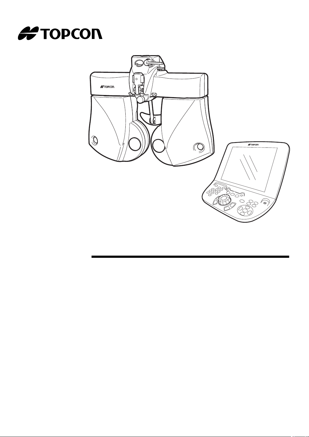
USER MANUAL
CV-5000
COMPU VISION
CV-5000
Page 2

Page 3
INTRODUCTION
CAUTION : Federal law restricts this device to sale by or on the order of a physician.
Thank you for purchasing the TOPCON COMPU VISION CV-5000.
INTENDED USE / INDICATIONS FOR USE
This instrument is used to measure the refractive power of the eye and to test binocular
functionality.
FEATURES
This instrument has the following features:
The compact design lens chamber enables you to see the patient's face.
The distance acuity chart can be controlled by the 1Dial Controller.
The PD (pupil distance) and the anterior eye alignment can be checked even in a dark
optometry room.
The large 10.4-inch touch panel liquid crystal display unit is used to easily conduct an
examination or patient education.
"Help", "Dial Navigation" and other functions support the optometrist.
PURPOSE OF THIS MANUAL
This manual outlines the COMPU VISION CV-5000, including operating procedures, troubleshooting and cleaning.
To ensure safe and effective use of the instrument, carefully read "DISPLAY AND SYMBOLS
FOR SAFE USE" and "GENERAL SAFETY INFORMATION" and then use the instrument as
instructed.
Keep the user manual at hand for future reference.
1
Page 4

QR Code is registered trademarks of DENSO WAVE INCORPORATED in Japan and in other
countries.
1. No part of this manual may be copied or reprinted, in whole or in part, without prior written
permission.
2. The contents of this manual are correct to the best of our knowledge. Please inform us of
any ambiguous or erroneous descriptions, missing information, etc.
©2014 TOPCON CORPORATION
ALL RIGHTS RESERVED
2
Page 5

CONTENTS
INTRODUCTION ...............................................................................................................1
DISPLAY AND SYMBOLS FOR SAFE USE .................................................................. 10
GENERAL SAFETY INFORMATION .............................................................................. 12
HOW TO USE THIS USER MANUAL ............................................................................. 15
GENERAL MAINTENANCE INFORMATION ................................................................. 15
DISCLAIMERS ................................................................................................................ 16
WARNING DISPLAYS AND POSITIONS ....................................................................... 17
1.BEFORE USE
1.1 CHECKING THE ACCESSORIES ..................................................................................18
STANDARD ACCESSORIES .................................................................................... 18
OPTIONAL ACCESSORIES ...................................................................................... 19
1.2 COMPONENT NAMES AND FUNCTIONS ....................................................................20
1.2.1 MAIN UNIT(Measuring head) .................................................................................20
COMPOSITION OF PARTS WHICH CONTACT THE HUMAN BODY ..................... 21
1.2.2 POWER SUPPLY UNIT for CV-5000 (BUILT-IN PC TYPE) ...................................22
1.2.3 1DIAL CONTROLLER ............................................................................................24
OPERATION SWITCHES(CONTROLLER UNIT) ..................................................... 25
BASIC OPERATION SWITCHES ............................................................................25
ITEM SELECTION SWITCHES ...............................................................................27
UTILITY SWITCHES ...............................................................................................28
TEST SCREEN (MONITOR UNIT) ............................................................................ 31
DATA DISPLAY UNIT ..............................................................................................32
VISUAL ACUITY CHART OPERATION UNIT .........................................................36
FUNCTION BUTTON ..............................................................................................36
2.INSTALLATION
2.1 INSTALLING THE MEASURING HEAD .........................................................................37
LEVEL ADJUSTMENT ............................................................................................... 37
INSTALLING AND REMOVING THE FACE SHIELD AND FOREHEAD REST ........ 37
ASSEMBLY/INSTALLATION OF NEAR-POINT ROD AND NEAR-POINT CARD .... 38
2.2 CONNECTING THE MEASURING HEAD, 1DIAL CONTROLLER ................................ 39
2.3 CONNECTING THE VISUAL ACUITY CHART ..............................................................40
CONNECTING A DEVICE TO RS-232C (ACP-8, MC-3.) ......................................... 40
CONNECTING A DEVICE TO INFRARED COMMUNICATION (ACP-8, MC-3.) ...... 40
CONNECTING A DVI / HDMI DEVICE (PC-50S, PC-50SB, MC-4S, MC-5S) .......... 40
3
Page 6

2.4 REGISTERING THE VISUAL ACUITY CHART .............................................................. 41
3.BASIC OPERATIONS
3.1 FLOW OF OPERATIONS ...............................................................................................43
3.2 PREPARATION BEFORE MEASUREMENT ..................................................................43
3.2.1 PREPARATION FOR TEST ...................................................................................43
3.2.2 DATA INPUT ...........................................................................................................45
3.3 TEST ...............................................................................................................................48
SELECT THE TEST CHART AND EXECUTE THE TEST. ....................................... 48
SELECT THE PROGRAM COURSE AND EXECUTE THE TEST. ........................... 48
SELECT THE TEST NAME AND EXECUTE THE TEST. ......................................... 49
3.4 PRESCRIPTION .............................................................................................................50
3.5 OUTPUTTING THE RESULT .........................................................................................50
3.6 RESETTING ....................................................................................................................51
4.GENERAL OPTOMETRY PROCEDURE
4.1 DATA INPUT ...................................................................................................................52
4.2 FAR-POINT REFRACTIVE POWER MEASUREMENT .................................................52
REFRACTIVE POWER MEASUREMENT BY USING CROSS CYLINDER ............. 52
REFRACTIVE POWER MEASUREMENT USING ASTIGMATISM TEST CHART ... 53
4.3 NEAR-POINT REFRACTIVE POWER MEASUREMENT ...............................................53
4.4 BINOCULAR MEASUREMENT ......................................................................................54
FAR-POINT PHORIA ................................................................................................. 54
NEAR-POINT PHORIA .............................................................................................. 54
5.OPERATION FOR TESTS
5.1 VISUAL ACUITY TEST/SPHERICAL POWER/CYLINDER POWER CORRECTION ....55
5.1.1 VISUAL ACUITY MEASUREMENT ........................................................................55
5.1.2 R/G TEST ...............................................................................................................56
5.1.3 ASTIGMATISM TEST .............................................................................................57
5.1.4 CROSS CYLINDER TEST (JACKSON CROSS) ....................................................59
5.1.5 CROSS CYLINDER TEST (TOPCON CROSS) .....................................................61
5.1.6 SMART CROSS TEST ...........................................................................................62
5.1.7 BALANCE TEST (POLARIZATION) .......................................................................64
5.1.8 BALANCE TEST (POLARIZATION: 2-COLOR) .....................................................65
5.1.9 BALANCE TEST (PRISM) ......................................................................................66
5.2 PHORIA TEST ................................................................................................................68
5.2.1 PHORIA TEST (POL. CROSS) ...............................................................................68
4
Page 7

5.2.2 PHORIA TEST (CROSS RING) ..............................................................................70
5.2.3 PHORIA TEST (MADDOX) .....................................................................................71
5.2.4 HORIZONTAL PHORIA MEASUREMENT (PRISM SEPARATION) ......................74
5.2.5 VERTICAL PHORIA MEASUREMENT (PRISM SEPARATION) ............................76
5.3 OTHER BINOCULAR FUNCTION TESTS .....................................................................78
5.3.1 FIXATION DISPARITY TEST (POL. CROSS WITH FIXATION TARGET) ............78
5.3.2 CONVERGENCE/DIVERGENCE ...........................................................................80
5.3.3 Vertical vergence ....................................................................................................83
5.3.4 STEREO TEST .......................................................................................................85
5.3.5 COINCIDENCE TEST (H) (Only for ACP-8) ...........................................................87
5.3.6 COINCIDENCE TEST (V) .......................................................................................89
5.3.7 WORTH 4 DOTS TEST ..........................................................................................91
5.3.8 SHEARD'S CRITERIA ............................................................................................93
5.4 NEAR-POINT TEST ........................................................................................................95
5.4.1 ADD TEST ..............................................................................................................95
5.4.2 MONOCULAR ADD TEST ......................................................................................96
5.4.3 MINUS LENS AMPLITUDE MEASUREMENT .......................................................98
5.4.4 POSITIVE RELATIVE ACCOMMODATION MEASUREMENT ............................100
5.4.5 NEGATIVE RELATIVE ACCOMMODATION MEASUREMENT ...........................102
5.4.6 AC/A ......................................................................................................................104
6.CONVENIENCE FUNCTIONS
6.1 USING THE DATA OF PERIPHERAL DEVICES .........................................................107
6.1.1 CONNECTING PERIPHERAL DEVICES .............................................................108
6.1.2 SETTING FOR CONNECTION .............................................................................109
SETTING FOR SERIAL CONNECTION .................................................................. 109
6.1.3 IMPORTING THE DATA FROM OTHER DEVICES .............................................111
SETTING THE DATA CAPTURING METHOD ........................................................ 111
DISPLAY RM/CL DATA LIST .................................................................................. 112
LOAD LAST DATA FROM RM/CL ........................................................................... 114
LOAD LAST DATA FROM SELECTED SOURCE ................................................... 114
When you select [RM] ............................................................................................114
When you select [CL] .............................................................................................114
When you select [RM+CL] .....................................................................................114
IMPORT DATA FILE ................................................................................................ 114
6.1.4 INPUTTING OTHER DATA EXCEPT "SUBJECTIVE" .........................................115
6.2 TESTS ...........................................................................................................................116
6.2.1 CHECKING THE TEST METHOD ........................................................................116
HELP/MINI HELP UTILITY ...................................................................................... 116
DIAL NAVIGATION UTILITY ................................................................................... 117
5
Page 8

6.2.2 CONVENIENCE FUNCTIONS DURING TEST ....................................................117
SELECTING THE CHANGING STEP FOR LENS ................................................... 117
CHANGING THE AUXILIARY LENS ....................................................................... 118
SELECTING THE TYPE OF OCCLUSION .............................................................. 119
SETTING THE VISUAL ACUITY VALUE DIRECTLY .............................................. 120
INPUTTING THE VISUAL ACUITY VALUE SCORE ............................................... 121
SETTING THE CYLINDER AXIS DIRECTLY .......................................................... 122
CANCELLING THE PRISM TEMPORARILY ........................................................... 122
SELECTING THE POLARIZATION LENS ............................................................... 123
DISPLAYING/HIDING THE REFERENCE DATA .................................................... 123
CHANGING THE REFERENCE DATA .................................................................... 124
CHANGING THE MAIN DATA ................................................................................. 125
CHANGING THE MAIN DATA AND REFERENCE DATA TO EACH OTHER ........ 126
TRANSPOSING THE SYMBOL OF CYLINDER POWER (POWER CONVERSION) ... 126
RECORDING AND DISPLAYING THE PRESCRIPTION DATA ............................. 127
CANCELING THE NEAR-POINT CORRECTION TEMPORARILY ......................... 127
6.2.3 OPERATING THE VISUAL ACUITY CHART .......................................................128
APPLYING THE MASK TO THE TEST CHART ...................................................... 128
SETTING THE R/G FILTER TO THE TEST CHART ............................................... 129
CHANGING THE TEST CHART WITHOUT CHANGING THE TEST ..................... 129
TURNING ON/OFF THE VISUAL ACUITY CHART/NEAR-POINT ILLUMINATION 129
ADJUSTMENT OF NEAR-POINT CARD ................................................................ 130
Target name on the patient side ............................................................................130
6.2.4 TILTING DOWNWARD .........................................................................................131
6.3 REGISTRATION ...........................................................................................................132
6.3.1 CUSTOMIZING THE CHART PAGE ....................................................................132
CHANGING THE TEST CHART LAYOUT ON THE CHART PAGE ....................... 132
CHANGING THE TEST RELATED TO THE TEST CHART .................................... 133
CHANGING THE TEST CHART USED IN CROSS CYLINDER TEST ................... 135
6.3.2 CUSTOMIZE THE TEST PROCEDURE ..............................................................137
6.4 EXPLANATION .............................................................................................................140
6.4.1 DATA TO BE PRINTED ........................................................................................140
6.4.2 USING THE PATIENT EDUCATION TOOLS FOR THE PATIENT ......................144
OPERATIONS ENABLED BY THE EXPLANATION TOOLS .................................. 144
Human eye ............................................................................................................144
Progressives ..........................................................................................................147
Accommodation .....................................................................................................147
Near Check ............................................................................................................148
Eye Message .........................................................................................................148
6.5 CONTROL BY USING iPad (*) .....................................................................................149
6.5.1 PREPARATION FOR USE ...................................................................................149
6
Page 9

OBJECTS TO BE PREPARED ................................................................................ 149
DOWNLOAD OF Microsoft Remote Desktop Client Application "RD Client" ........... 150
CONNECTING THE DEVICES ................................................................................ 153
SETTING OF IP ADDRESS ..................................................................................... 153
SETTING OF iPad ................................................................................................... 154
SETTING OF KB-50S .............................................................................................. 157
SETTING OF RD Client ........................................................................................... 158
CONNECTION FROM iPad TO CV-5000 ................................................................ 163
6.5.2 EXAMINATION SCREEN AND BASIC OPERATION ...........................................166
TOOL BAR ............................................................................................................... 167
OPERATION WINDOW ........................................................................................... 169
Basic operation of data operation button ...............................................................170
Examinations and navigation icons .......................................................................171
MAIN DATA DISPLAY AREA/PD DISPLAY AREA ................................................. 176
SIDE BUTTON ......................................................................................................... 176
6.5.3 HOW TO INPUT THE MEASUREMENT DATA OF OTHER DEVICES MANUALLY ..177
6.5.4 RETURNING TO KB-50S .....................................................................................178
7.MAINTENANCE
DAILY CHECKUPS .................................................................................................. 179
ORDERING CONSUMABLES ................................................................................. 179
USER MAINTENANCE ITEMS ................................................................................ 179
REPLACING THE FUSE ......................................................................................... 180
CLEANING ............................................................................................................... 181
Cleaning parts which contact the patient ...............................................................181
Cleaning the lens ...................................................................................................181
INSPECTING THE MEASURING HEAD MOUNTING SECTION ........................... 182
Point for inspection ................................................................................................182
SETTING THE PRINTER PAPER ........................................................................... 183
8.SETTING
8.1 BASIC OPERATION FOR "SETTINGS" MENU ...........................................................185
8.2 "SETTINGS" MENU LIST ............................................................................................. 187
8.2.1 General settings .................................................................................................... 190
8.2.2 Function settings ...................................................................................................192
8.2.3 Examination settings ............................................................................................. 195
8.2.4 Chart settings ........................................................................................................199
Chart page registration ............................................................................................ 201
Cross cylinder chart reg. .......................................................................................... 204
8.2.5 Course registrations ..............................................................................................205
7
Page 10

8.2.6 Data I/O settings ...................................................................................................208
System configurations .............................................................................................. 209
8.2.7 Screen settings .....................................................................................................214
8.2.8 Update ..................................................................................................................216
9.APPENDICES
9.1 LIST OF AUXILIARY LENS AND DIAL NAVIGATION ..................................................218
AUXILIARY LENS .................................................................................................... 218
DIAL NAVIGATION .................................................................................................. 220
9.2 SHAPE OF PLUG .........................................................................................................222
ABOUT THE BARCODE AND THE QR CODE OF THE USER MANUAL BACK COVER . 223
9.3 CORNEAL ALIGNING DEVICE ....................................................................................224
Conversion value (When the measured refractive power is plus notation) ............225
Conversion value (When the measured refractive power is minus notation) .........225
10.TROUBLE SHOOTING
TROUBLE SHOOTING GUIDE ............................................................................... 226
11.SPECIFICATIONS AND PERFORMANCE
................................................................................................................................. 239
12.GENERAL INFORMATION ON USAGE AND MAINTENANCE
INTENDED PATIENT POPULATION ...................................................................... 240
INTENDED USER PROFILE ................................................................................... 240
ENVIRONMENTAL CONDITIONS FOR USE ......................................................... 240
STORAGE, USAGE PERIOD .................................................................................. 240
ELECTRIC RATING ................................................................................................. 241
DIMENSIONS AND WEIGHT .................................................................................. 241
SYSTEM CLASSIFICATION .................................................................................... 242
OPERATING PRINCIPLE ........................................................................................ 242
CHECKPOINTS FOR MAINTENANCE ................................................................... 243
Maintenance by user .............................................................................................243
DISPOSAL ............................................................................................................... 243
PATIENT’S ENVIRONMENT ................................................................................... 244
ELECTROMAGNETIC COMPATIBILITY ................................................................. 245
REQUIREMENT TO THE EXTERNAL CONNECTION DEVICES .......................... 249
IT NETWORK ENVIRONMENT ............................................................................... 249
8
Page 11

Index ...................................................................................................................................251
END USER LICENSE AGREEMENT ................................................... 254
9
Page 12
DISPLAY AND SYMBOLS FOR SAFE USE
To encourage safe and proper use and to prevent danger to the operator and others or potential
damage to property, important cautionary messages are placed on the instrument body and
inserted in the user manual.
We suggest that everyone using the instrument understand the meaning of the following displays,
icons and text before reading the "GENERAL SAFETY INFORMATION" and observe all listed
instructions.
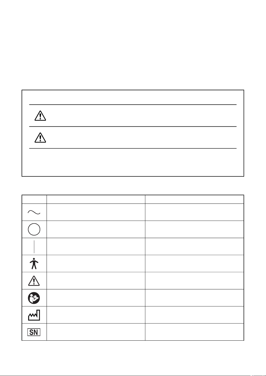
DISPLAYS
Display Meaning
WARNING
CAUTION
Injury refers to cuts, bruises, burns, electric shock, etc. which do not require hospital-
ization or extended medical treatment.
Physical damage refers to extensive damage to the building, nearby equipment and/
or surrounding furniture.
Incorrect handling by ignoring this display may lead to a risk of
death or serious injury.
Incorrect handling by ignoring this display may lead to personal
injury or physical damage.
SYMBOL
Symbol Description Description (French)
Alternating Current Courant alternatif
Off (power: disconnection from the
mains)
On (power: connection to the mains)
Éteint (courant: coupure avec le
secteur)
Allumé (courant: raccordement sur le
secteur)
10
Type B applied part Partie appliquée du Type B
General warning sign Symbole d'avertissement général
Refer to instruction manual/ booklet Voir le manuel/la brochure
Date of manufacture Date de fabrication
Serial number Numéro de série
Page 13
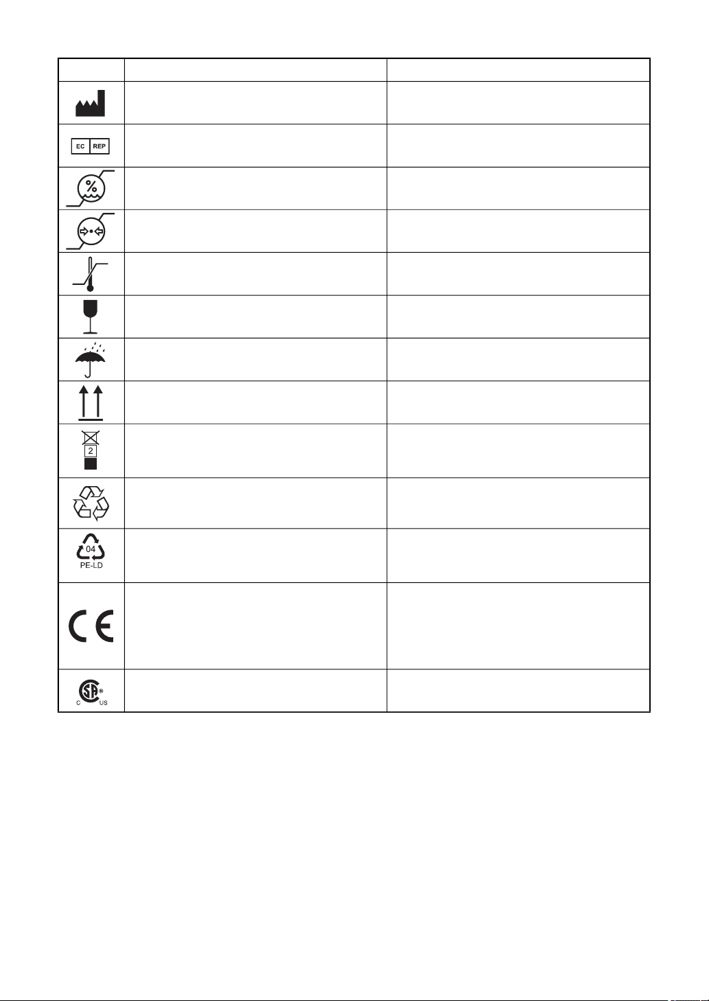
Symbol Description Description (French)
Manufacturer Fabricant
Authorised Representative in the
European Community
Humidity limitation Limite d'humidité
Atmospheric pressure limitation Limite de pression atmosphérique
Temperature limit Limite de température
Fragile, handle with care Fragile manipuler avec soin
Keep dry Garder au sec
This way up Vers le haut
Maximum number of identical packages which may be stacked on one
another.
General symbol for recovery/recyclable.
(for the package)
Représentant autorité pour l’Union
européenne
Nombre maximum d’emballages
identiques pouvant être empilés les uns
sur les autres.
Symbole général de tri sélectif.
(pour l’emballage)
Recycling symbol for plastic in the
package.
Low density polyethylene
Indicates that the product conforms to
the requirements of the Medical Device
Regulation(EU)2017/745 and of the
other applicable Union legislation
CSA listing mark Marque de certification CSA
Symbole de recyclage du plastique de
l'emballage.
Polyéthylène basse densité
Indique que le produit est conforme aux
exigences du Règlement (UE) 2017/745
relatif aux dispositifs médicaux et des
autres lois applicables de l'Union
Européenne
11
Page 14
GENERAL SAFETY INFORMATION
WARNING
Ensuring the Safety of Patients and Operators
Be careful not to bump the patient's eyes or nose with the instrument during operation.
The patient may be injured.
Preventing Electric Shocks and Fires.
To avoid fire and electric shock, install the instrument in a place free of water and other liquids.
To avoid fire and electric shock, do not put cups or other containers with liquids near the instru-
ment.
To avoid electric shock, do not insert metal objects into any openings, etc.
To avoid fire in the event of an instrument malfunction, immediately turn off the power switch
and unplug the cable if you see smoke coming from the instrument or if you detect other problems. Don't install the instrument where it is difficult to disconnect the power plug from the
outlet. Ask your dealer for repairs.
Modification of this instrument is not permitted.
To avoid electric shock and fire, do not disassemble, modify or repair the equipment.
Ask your dealer for repairs.
Electoric shock may cause bums or a possible fire. Turn the power switch OFF and unplug
the power cord before replacing the fuses. Replace only with fuses of the correct rating.
To avoid injury caused by electric shock, do not open the cover.
Ask your dealer for service.
To avoid fire and electric shock in case of leakage, be sure to use a grounded outlet. Do not
connect to outlets that are not grounded.
To avoid electric shock, be sure to remove the power cable from the instrument body before
removing the fuse cover for replacement.
Also, do not connect the power cable to the instrument body with the fuse cover left unfixed.
To avoid fire in the event of an instrument malfunction, use a properly rated fuse.
Proposition65 warning sentence
WARNING: This product can expose you to chemicals including Lead, which is known to
the State of California to cause birth defects or other reproductive harm. For more information
go to www.P65Warnings.ca.gov.
12
Page 15
CAUTION
Ensuring the Safety of Patients and Operators
When moving the instrument body up and down, be careful not to bump it against the patient's face.
The patient may be injured.
This instrument should only be used by skilled operators.
To prevent the instrument from tipping over or falling and to avoid injury, do not install the
instrument on an uneven, unsteady or sloping surface.
Do not put your hand between the mounting arm and the instrument. Your hand may be pinched.
To avoid injury due to contact, do not bring the patient's face close to the near-point rod.
To avoid injury caused by pinching when moving the monitor unit, do not place your hand
between the monitor unit and the main unit.
Install the devices (RM, CL and others), which will be connected with the optional accessories,
out of the CV-5000 patient's environment.
Do not to connect additional a power strip (it shall be not only in patient environment also in
outside of patient environment).
Install the visual acuity chart out of the CV-5000 patient's environment.
Install the devices (RM, CL and others) to be connected out of the CV-5000 patient's environment.
When tilting the instrument downward, place the measuring head away from the patient to pre-
vent him/her from being injured by colliding against it.
Do not tilt the instrument downward while the near-point rod is pulled down. The near-point rod
may hit the instrument or desk and damage the instrument.
To avoid injury caused by pinching when moving the monitor unit of the 1Dial Controller , do
not place your hand between the monitor unit and the controller unit.
• When you connect this instrument on the personal computer connected to a network, ensure
security properly in order to prevent the infection with computer virus, leak of information
and other troubles.
• When connected this instrument on the client server system, it is assumed that the data and
database files will be placed on the network. Manage the folders which save these files and
the access right to the files correctly.
• Manage the personal computer and media (recording media), which save the data obtained
and backed up by this instrument, in order to prevent the computer and media from being
wrongly used or taken out by the third party.
Preventing Electric Shocks.
To avoid damage to the instrument or an injury caused by electric shock, turn off the power
switch and unplug the power cord before cleaning the instrument.
To avoid electric shock, do not touch the external connection terminal and the patient at the
same time.
To avoid electric shock, do not handle the plugs with wet fingers.
13
Page 16
Ensuring Security
• When connecting this instrument to an external device through LAN, apply the security
update to the external device, make use of anti-virus software and take other countermeasures against computer virus properly.
• Do not connect any USB storage device that is not checked with the anti-virus software to the
USB port of this instrument.
• When connecting this instrument to an external device through LAN, set the ID and password
of the user to the external device.
• When outputting data to the shared folder on an external device from this instrument, set a
proper user ID and password to the shared folder.
Electromagnetic Compatibility (EMC)
This instrument has been tested (with 100V/120V/230V) and found to comply with IEC 606011-2:Ed.4.0 2014.
This instrument radiates radio frequency energy within standard and may affect other devices
in the vicinity.
If you have discovered that turning on/off the instrument affects other devices, we recommend
you change its position, keep a proper distance from other devices, or plug it into a different
outlet.
Please consult the dealer from whom you purchased the instrument if you have any additional
questions.
14
Page 17
HOW TO USE THIS USER MANUAL
• Before using the CV-5000 instrument, read the cautions described on P.1 to P.17.
• For connecting to other devices, read "6.1.1 CONNECTING PERIPHERAL DEVICES" on P.108.
• For quick start up, refer to "3. BASIC OPERATIONS" on P.43 first.
• For setup, refer to "6. CONVENIENCE FUNCTIONS" on P.107.
• The following symbols are used in this manual. Please understand these symbols and their
meaning and use the instrument correctly.
: Describes the convenience functions and the cautions to ensure safe use.
: Describes the location of supplemental or additional information.
• The following abbreviations indicate the devices relevant to the instrument.
Abbreviation Device
RM Auto refractometer
KR Auto kerato-refractometer
CL Computerized lensmeter
EZ EZ meter
ACP Auto chart projector
MC Mirror chart
PC PIXELCHART
GENERAL MAINTENANCE INFORMATION
To ensure the safety and performance of this instrument, all maintenance work, unless specified in
this manual, shall be conducted by trained service engineers.
The following maintenance tasks may be performed by the user.
For details, see the relevant parts of this manual as specified below.
Replacing the face shield/forehead rest
The forehead rest and face shield on this instrument may be replaced by the user.
: Refer to " INSTALLING AND REMOVING THE FACE SHIELD AND FOREHEAD
REST" on P.37 for handling instructions.
Replacing the fuse
The fuses on this instrument may be replaced by the user.
: For details, refer to " REPLACING THE FUSE" on P.180.
Inspecting the instrument
It is recommended to inspect the mounting section of the CV-5000 and the system table periodically to ensure they are attached properly.
: Refer to " INSPECTING THE MEASURING HEAD MOUNTING SECTION" on P.182.
15
Page 18

DISCLAIMERS
TOPCON shall not take any responsibility for damage due to fire, earthquakes, actions
by third persons and other accidents, or damage due to negligence and misuse by the
user and any use under unusual conditions.
TOPCON shall not take any responsibility for damage derived from inability to properly
use this instrument, such as loss of business profit and suspension of business.
TOPCON shall not take any responsibility for damage caused from using this instru-
ment in a manner other than that described in this user manual.
TOPCON is not responsible for any damage caused by unauthorized access from out-
side, malware or viruses.
Diagnoses made shall be the responsibility of the user and TOPCON shall not take
any responsibility for the results of such diagnoses.
16
Page 19
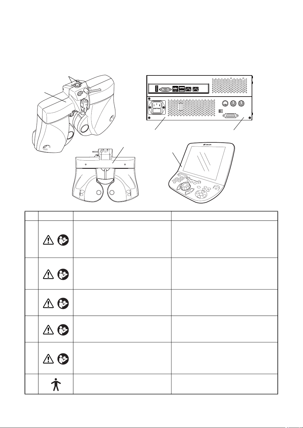
WARNING DISPLAYS AND POSITIONS
IR
KB
DC 12V
CV
ACP/MC COM3
To ensure safety, the machine provides warning displays.
Use the instrument correctly by observing the display instructions. If any of the following display
labels are missing, contact your TOPCON dealer or your local Topcon office listed on the back
cover of this manual.
3
4
1
2
6
5
No. Label Meaning Signification
WARNING
Electoric shock may cause bums or a
1
possible fire. Turn the power switch
OFF and unplug the power cord before
replacing the fuses. Replace only with
fuses of the correct rating.
Un choc electrique causerait une brulure ou
un incendie. Mettre l'interrupteur sur arret et
debrancher la prise avant de remplacer des
fusibles. Utiliser seulement avec des fusibles de la classe correcte.
WARNING
2
To avoid injury caused by electric shock,
do not open the cover.
Ask your dealer for service.
Ne pas ouvrir le couvercle pour éviter les
blessures causées par un choc électrique.
Demander au revendeur d'effectuer le service.
CAUTION
3
Do not put your hand between the
mounting arm and the instrument. Your
hand may be pinched.
Ne pas placer la main entre le bras support
et l’ instrument. La main pourrait être
pincée.
CAUTION
4
To avoid injury due to contact, do not
bring the patient’s face close to the nearpoint rod.
Pour éviter les blessures dues aux contacts,
ne pas faire approcher la face du patient de
la tige à point de vision rapprochée.
CAUTION
5
6
To avoid injury caused by pinching when
moving the monitor unit, do not place
your hand between the monitor unit and
the main unit.
Degree of protection against electric
shock
: TYPE B APPLIED PART
Pour éviter les blessures dues aux pincements en opérant l’unité de moniteur, ne pas
placer la main entre l’unité de moniteur et
l’unité principale.
Degré de protection contre les chocs électriques
: TYPE B PARTIE D'APPLICATION
MISE EN GARDE
MISE EN GARDE
PRÉCAUTION
PRÉCAUTION
PRÉCAUTION
17
Page 20
1. BEFORE USE
INSTRUCTION MANUAL
USER MANUAL
1.1 CHECKING THE ACCESSORIES
CAUTION
Install the devices (RM, CL and others), which will be connected with
the optional accessories, out of the CV-5000 patient's environment.
STANDARD ACCESSORIES
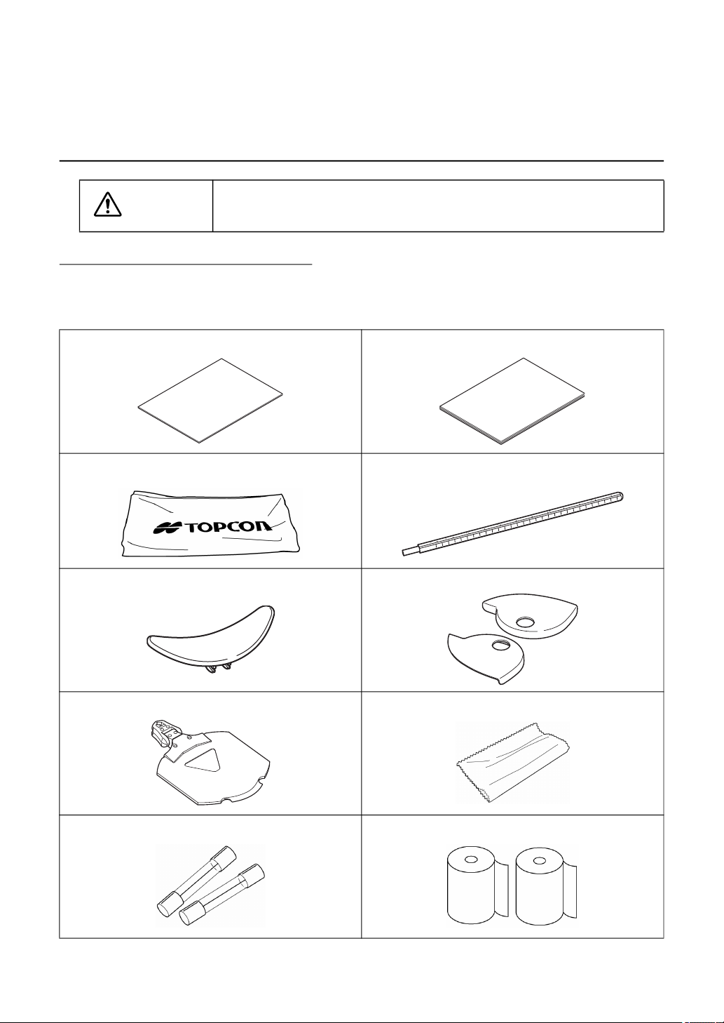
Upon unpacking, make sure that all the following standard accessories are included. Figures
in ( ) are the quantities.
Instruction Manual * User manual (1)
Dust cover (1) Near-point rod (1)
Forehead rest (1) Face shield (2)
Near-point card and card holder (1 each) Silicone cloth (1)
Fuses (2) Printer paper (2)
18
1. BEFORE USE
Page 21
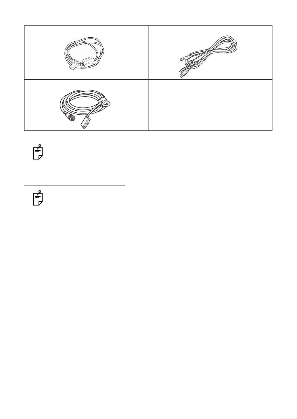
Power cord (1)
The shape is different according to the destination.
Measuring head connection cable (1)
*Depending on the destination, this is not attached.
Use the standard accessories except the following units in the patient's environment.
• User manual
• Dust cover
• Silicone cloth
OPTIONAL ACCESSORIES
The optional accessories must be connected by a service engineer. If you have purchased any optional accessories, contact a service engineer.
1Dial Controller connection cable (1)
• Measuring head connection cable (14m)
When a longer cable than the measuring head connection cable (length: 8m)
which is a standard accessory, is necessary, this cable of length 14m should be used.
• Communication cable (DIN/DIN)
This cable is used to connect KR, CL and the visual acuity chart.
Both ends of the cable are the DIN connector type.
• Communication cable (DIN/D-sub)
This cable is used to connect KR, CL, etc.
One end of the cable is the DIN connector type and the other is the D-SUB 9-pin type.
• Infrared communication unit
This unit is used to perform infrared communication with the visual acuity chart.
• PIXELCHART (PC-50S)
This visual acuity chart operates in linkage with the CV system.
• PIXELCHART (PC-50SB)
This visual acuity chart operates in linkage with the CV system.
• Mirror Chart (MC-4S)
This visual acuity chart operates in linkage with the CV system.
• Mirror Chart (MC-5S)
This visual acuity chart operates in linkage with the CV system.
• 1 DIAL CONTROLLER KB-50S (for combination of KB-50S operation)
• POWER SUPPLY UNIT for CV-5000 (BUILT-IN PC TYPE) (for combination of KB-50S or
mouse operation)
19
1. BEFORE USE
Page 22
• POWER SUPPLY UNIT for CV-5000 (PC EXTERNAL TYPE) (for combination of PC operation)
* The PC and Mouse are commercial products. For usable external devices and connection
cables, please contact your local distributor or contact address on the back cover.
1.2 COMPONENT NAMES AND FUNCTIONS
CAUTION
Use all the components in the patient's environment.
To avoid electric shock, do not touch the external connection terminal
and the patient at the same time.
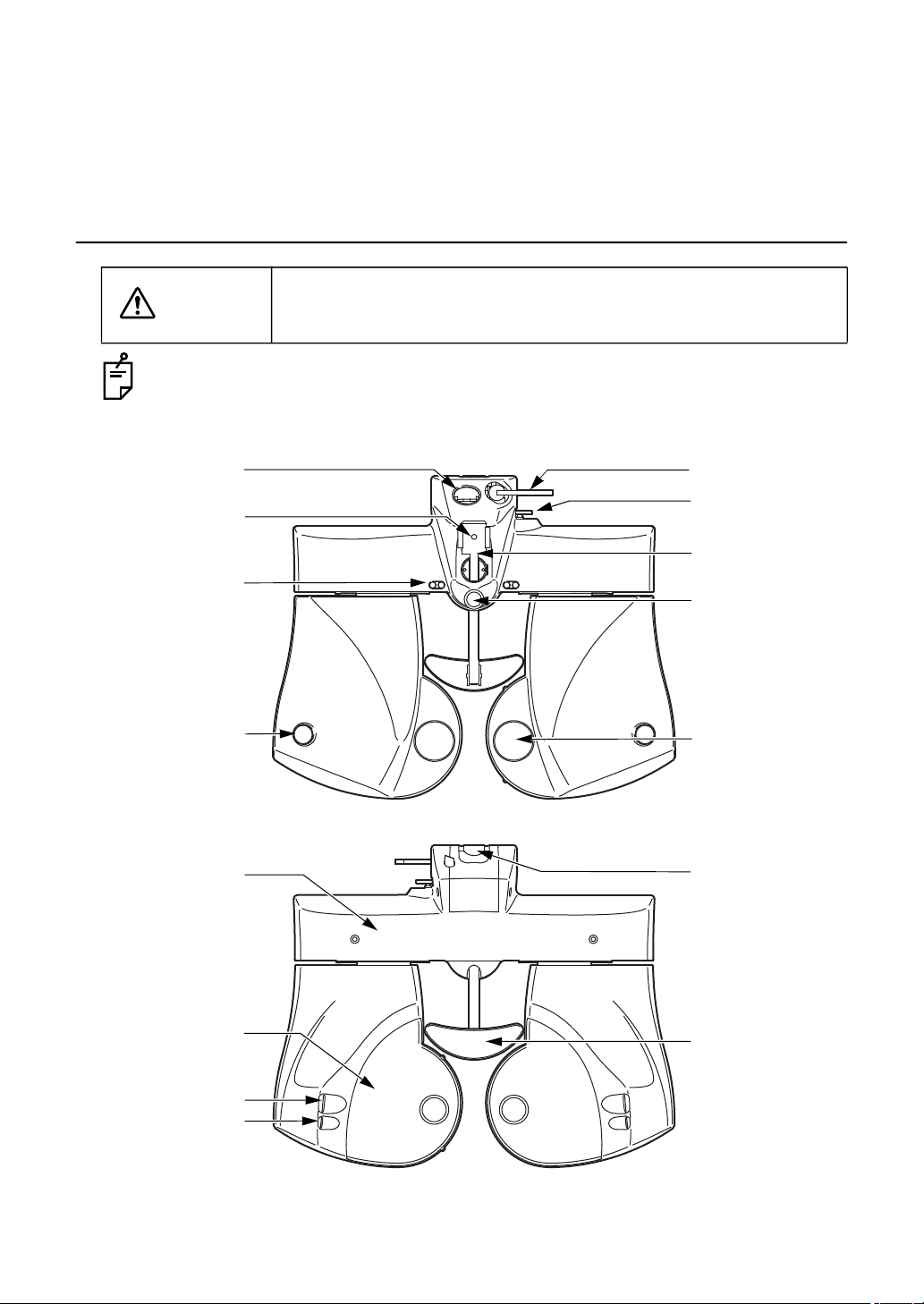
1.2.1 MAIN UNIT(Measuring head)
(9)
(6)
(12)
(2)
(13)
(4)
(5)
(3)
(1)
20
1. BEFORE USE
(15)
(10)
(8)
(11)
(14)
(7)
Page 23

(1) Examination window ......... The patient's eyes are observed through this window, and the
display lenses are set here.
(2) Corneal vertex distance windowThe position of the patient's cornea can be observed
through this window.
(3) Forehead rest knob...........The position of the forehead rest can be adjusted by moving
this knob backward/ forward.
(4) Leveling knob....................Levels the measuring head.
(5) Near-point rod holder........The near-point rod is inserted and attached here.
(6) Clamp screw ..................... Retains the near-point rod.
(7) Forehead rest....................The patient's forehead rests here.
(8) Cornea alignment scale ....Measures the corneal vertex position.
(9) Level ................................. Indicates the horizontal position for the level adjustment.
(10) Face shield........................The patient's face rests here.This cover can be removed.
(11) Cornea illumination ...........Illuminates the anterior eye segment to check the PD easily
even during examination in a dark room.
(12) Near-point illumination ......Illuminates the near-point target.
(13) Tilt locking lever ................ Adjusts the angle of the tilted measuring head and fixes it.
(14) Arm mounting shaft...........Mounts the instrument on the arm, etc.
(15) PD cover ........................... The cover for holding when tilting the head.
COMPOSITION OF PARTS WHICH CONTACT THE HUMAN BODY
Forehead rest : Polypropylene resin (Type B applied part)
Face shield : Polypropylene resin
21
1. BEFORE USE
Page 24
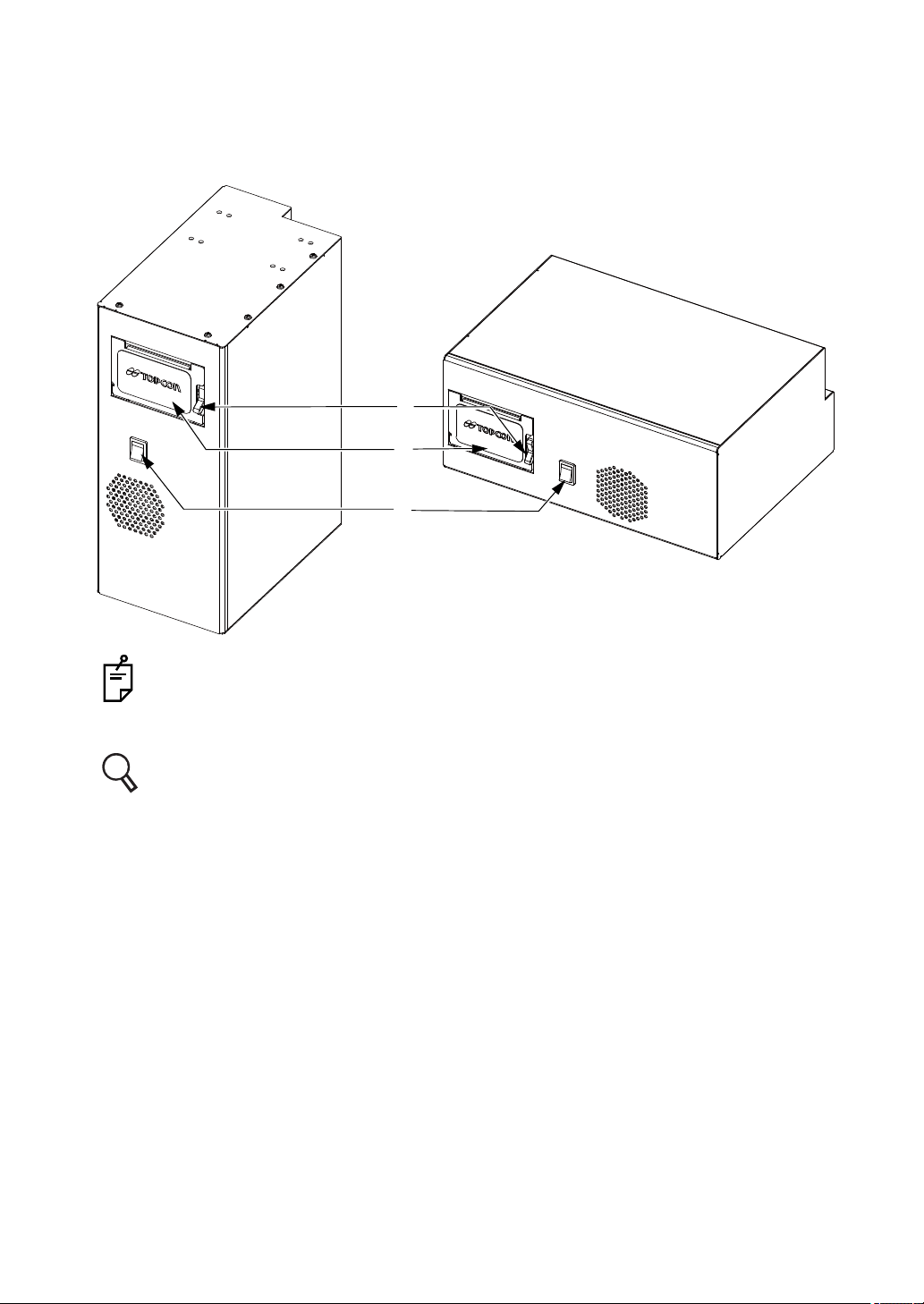
1.2.2 POWER SUPPLY UNIT for CV-5000 (BUILT-IN PC TYPE)
Front surface
(1)
(2)
(3)
The orientation of the printer should be changed to match the type of installation.
(1) Cover release lever...........Opens the printer cover.
For installation of the printer paper, refer to " SETTING THE PRINTER PAPER" on
P.183.
(2)Printer cover .........................Open to access the printer paper.
(3) Power switch..................... Turns on/off the power.
22
1. BEFORE USE
Page 25
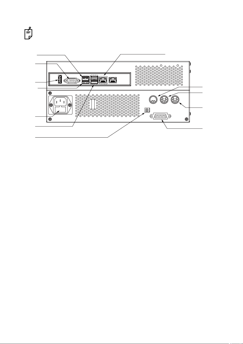
Rear panel
(9)
(10)
(11)
(12)
(13)
(4)
(5)
(6)
(7)
(8)
(14)
(15)
IR
KB
DC 12V
CV
ACP/MC COM3
Only use the connector described in this chapter.
(4) VGA connector.....................Used to connect monitor.
(5) HDMI connector .................. Used to connect the pixel chart and mirror chart (optional).
(6) Fuse holder .........................The fuse is set in this holder.
(7) USB connector.....................Used to connect a USB device.
Connect the1Dial Controller to the DC jack for KB in addition
to this connector.
(8) DC jack for KB ....................Used to connect 1Dial Controller.
(9) LAN connector ....................Used to connect the LAN cable.
(10) IR connector.......................Used to connect the infrared communication unit (option).
(11) ACP/MC connector ............Used to connect the visual acuity chart with a serial connection.
(12) COM3 connector................Used to connect RM or CL.
(13) CV connector ....................Used to connect the measuring head.
(14)COM8 connector.................Used to connect RM or CL.*
(15)COM7 connector.................Used to connect RM or CL.*
* For the recognition of COM7 and COM8, when both of them are used, they are set as shown
in the above figure. When one of COM7 and COM8 is used, it is set as "COM7" by the instrument's system.
You should use the specified conversion adapter. For details, please contact the agency you
have purchased.
23
1. BEFORE USE
Page 26
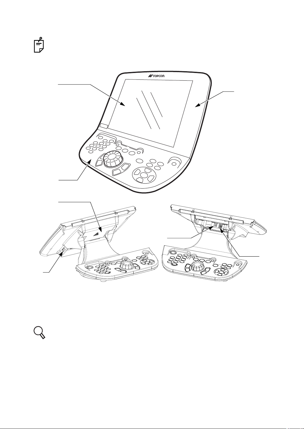
1.2.3 1DIAL CONTROLLER
In this user manual, the buttons of the controller unit are referred to as "switches" and,
when using any of these switches, the term "Press the switch" is used.
The buttons of the monitor screen are referred to as "buttons" and, when using any of
these buttons, the term "Touch the button" is used.
(2)
(3)
(1)
(4)
(6)
(7)
(5)
(1)Monitor unit...........................You can change the monitor angle.
(2)Monitor.................................. Displays the test screen. This is a touch-panel screen which
has built in "on screen" buttons which can be operated by
touching the desired selection directly on the panel.
(3)Controller unit .......................The operation switches are arranged on this unit.
For the operation switches, refer to " OPERATION SWITCHES(CONTROLLER UNIT)"
on P.25.
(4)Connector cover ................... This is used for the connector that should connect the 1Dial
Controller.
(5)USB connector A...................Connect a USB device to this connector.
(6)DC connector........................ Connect the DC cable side of the 1Dial Controller cable to this
connector.
(7)USB connector B ..................Connect the USB cable side of the 1Dial Controller cable to
this connector.
24
1. BEFORE USE
Page 27
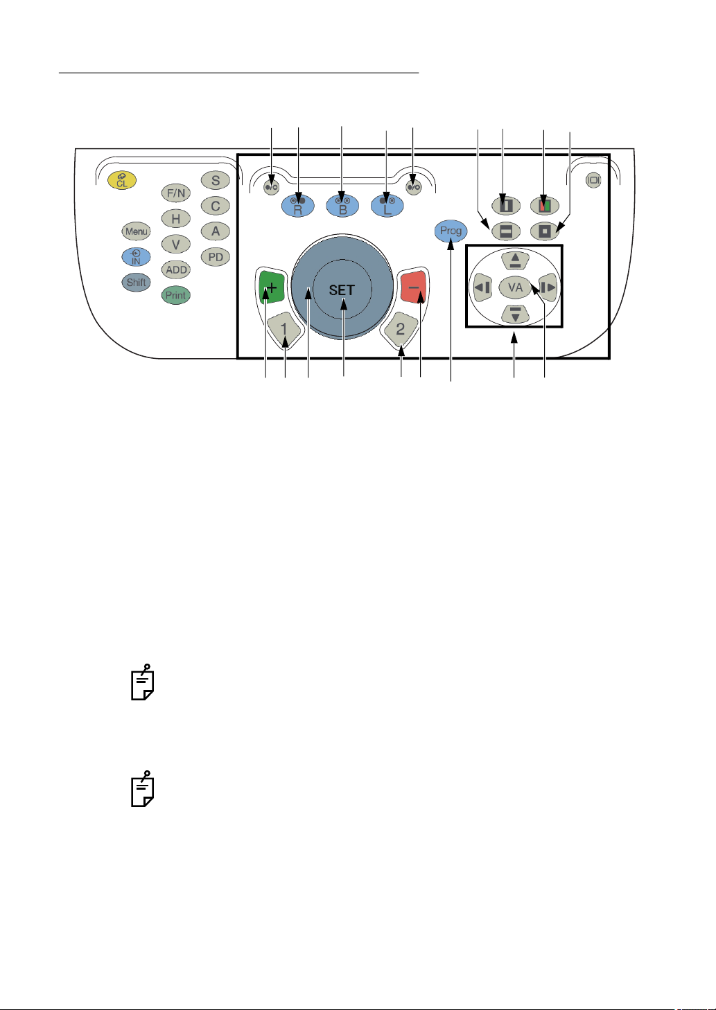
OPERATION SWITCHES(CONTROLLER UNIT)
BASIC OPERATION SWITCHES
(10) (7) (9) (8) (10) (15) (14) (16)(17)
(5)
(1) Dial
This dial is used to adjust the sphere, cylinder and axis values.
Select the value to be adjusted depending on the procedure. (Sphere, Cylinder or
Axis)
Turning the dial to the right increases the "minus" value
Turning the dial to the left increases the "plus" values
(2) [SET] switch
This switch is used to advance the course program by 1 step.
Hold down the [Shift] switch and then press the set switch to return to the previous
step when using a program.
This is also used as a response switch in the smart cross cylinder test.
(3) [1] switch
The cross cylinder lens with green frame is selected.
In the monocular mode, the cross cylinder lens is set to the eye to be tested and
the test starts.
In the binocular mode, the test starts automatically with the right eye test mode.
(4) [2] switch
The cross cylinder lens with red frame is selected.
In the monocular mode, the cross cylinder lens is selected for the eye to be
tested and the test starts.
In the binocular mode, the test starts automatically with the right eye test mode.
(1)
(2) (6) (12) (13)(3) (4)
(11)
(5) [+] switch (green)
Each time you press this switch, the value is changed toward the positive side by 1
step.
This is used as a response switch in the smart cross cylinder test.
1. BEFORE USE
25
Page 28
(6) [-] switch (red)
Each time you press this switch, the value is changed toward the negative side by 1
step.
This is used as a response switch in the smart cross cylinder test.
(7) [R] switch
Specify the right eye for the test.
The left eye is occluded depending on the specific test.
(8) [L] switch
Specify the left eye for the test.
The right eye is occluded depending on the specific test.
(9) [B] switch
Both eyes are measured. Both eyes are open.
(10) [ / ] switch (Occlusion control switch)
Press this switch, and the occluder is set to the right or left eye. Press this switch
again, and the occluder is removed.
Press this switch while pressing the [Shift] switch, and you can change the type of the
occluder.
(11) [Prog] switch
Press the [Prog] switch, and the test courses are displayed.
Hold down the [Shift] switch and then press the [Prog] switch to select the test list.
(12) [Move] switch
You can move the selected item for the acuity masks and list of tests.
• [ ] [] switch : Moves the item upward.
• [ ] [] switch : Moves the item downward.
• [ ] [] switch : Moves the item to the left.
• [ ] [] switch : Moves the item to the right.
(13) [VA] switch
This switch is used to input the measured visual acuity.
(14) [ ] switch (Vertical mask)
Inserts and removes the vertical mask.
(15) [ ] switch (Horizontal mask)
Inserts and removes the horizontal mask.
(16) [ ] switch (R/G)
Inserts and removes the red/green filter.
(17) [ ] switch (Single character mask)
Inserts and removes the character mask.
26
1. BEFORE USE
Page 29
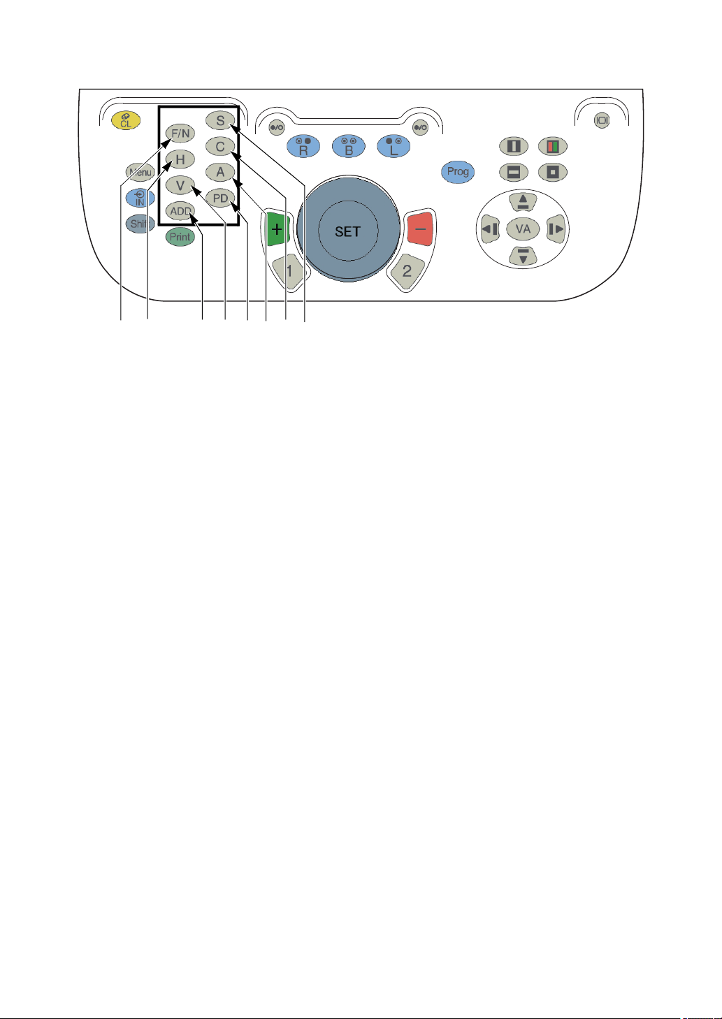
ITEM SELECTION SWITCHES
(1) (7) (8)(6) (5) (4) (3) (2)
(1) [F/N] switch
Change to the far- and near-point test modes.
(2) [S] switch
The mode to operate the spherical refractive power is selected.
In the near-point test mode, this switch is used to access the additional refractive
power operation mode.
(3) [C] switch
The mode to operate the cylinder refractive power is selected.
(4) [A] switch
The mode to operate the cylinder axis is selected.
(5) [PD] switch
The mode to operate PD is selected.
(6) [ADD] switch
The mode to operate the ADD refractive power is selected.
This switch does not work in the far-point test.
(7) [H] switch
The mode to operate the horizontal prism is selected.
(8) [V] switch
The mode to operate the vertical prism is selected.
27
1. BEFORE USE
Page 30
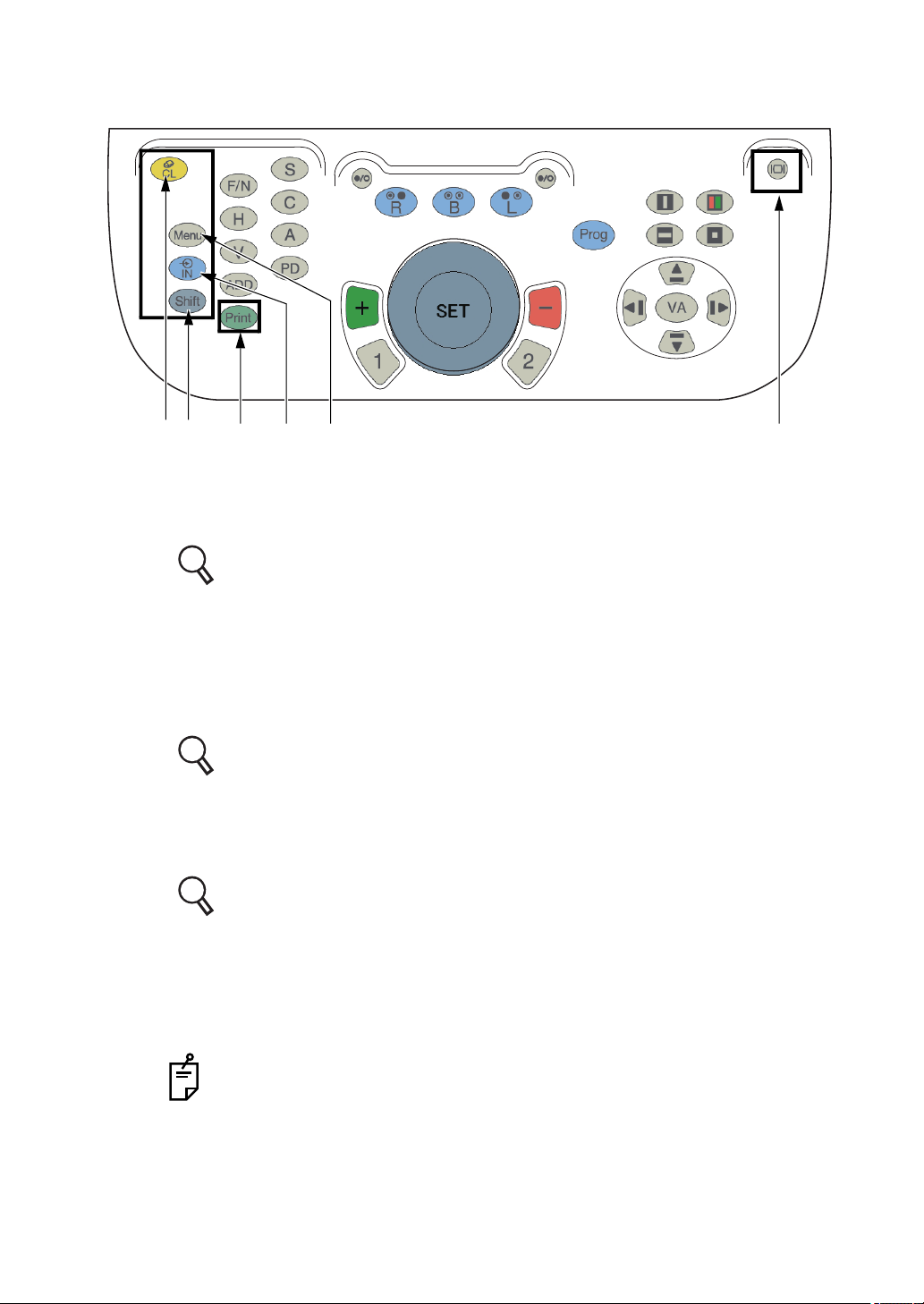
UTILITY SWITCHES
(4) (3)(6) (1) (5)(2)
(1) [Menu] switch
The patient education tools are displayed.
Press this switch with the [Shift] switch together, and the setting menu is displayed.
Refer to "6.4.2 USING THE PATIENT EDUCATION TOOLS FOR THE
PATIENT" on P.144 for the details of the tools.
Refer to "8.2 "SETTINGS" MENU LIST" on P.187 for the details of the set-
ting menu.
(2) [IN] switch
This switch is used to input the data of the connected external devices such as RM,
CL etc.
Refer to "6.1.3 IMPORTING THE DATA FROM OTHER DEVICES" on P.111 for
details.
(3) [Print] switch
Prints the test results.
Data can be output to a computer or other device depending on the configuration.
Refer to "8.2.2 Function settings" on P.192 for details.
(4) [CL] switch
The system will be reset and all values returned to the initial status of test.
(5) [|
|] switch
Turns off the display on the monitor. To turn it on again, turn the dial or press any
switch.
This switch cannot be used while the "Settings" menu is displayed.
28
1. BEFORE USE
Page 31
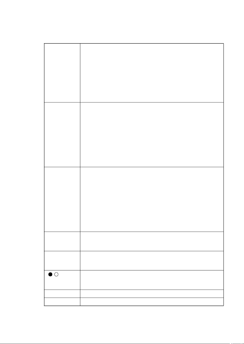
(6) [Shift] switch
This switch can be used while pressing other switches or touching the buttons on the
monitor screen as mentioned below.
[Dial]
• While operating the sphere and ADD:
When pressing the [Shift] switch, the changing step is 3.00D.
• While operating the cylinder:
When pressing the [Shift] switch, the changing step is 1.00D.
• While operating the axis:
When pressing the [Shift] switch, the changing step is 15.
• While operating the horizontal/vertical prism:
When pressing the [Shift] switch, the changing step is 1.00.
• While operating PD:
When pressing the [Shift] switch, the changing step is 1mm.
[+] switch
• While operating the sphere and ADD:
When pressing the [Shift] switch, the changing step is +3.00D.
• While operating the cylinder:
When pressing the [Shift] switch, the changing step is +1.00D.
• While operating the axis:
When pressing the [Shift] switch, the changing step is +15.
• While operating the horizontal/vertical prism:
When pressing the [Shift] switch, the changing step is 1.00 BI/
BD.
• While operating PD:
When pressing the [Shift] switch, the changing step is +1mm.
[-] switch
• While operating the sphere and ADD:
When pressing the [Shift] switch, the changing step is -3.00D.
• While operating the cylinder:
When pressing the [Shift] switch, the changing step is -1.00D.
• While operating the axis:
When pressing the [Shift] switch, the changing step is -15.
• While operating the horizontal/vertical prism:
When pressing the [Shift] switch, the changing step is 1.00
BO/BU.
• While operating PD:
When pressing the [Shift] switch, the changing step is -1mm.
[R] switch You can change powers only for the right eye lens when both eyes
are open. (If the left eye is occluded, the occlusion will be canceled.)
[L] switch You can change powers only for the left eye lens when both eyes
are open. (If the right eye is occluded, the occlusion will be canceled.)
[ / ] switch Each time you press the switch, the type of occlusion is changed
and set. (Refer to " SELECTING THE CHANGING STEP FOR
LENS" on P.117.)
[Menu] switch Displays the "Settings" menu.
[Prog] switch Displays "Exam list".
29
1. BEFORE USE
Page 32
[SET] switch This becomes functional while the "Custom" program is being exe-
cuted. Press the switch, and the system returns to the previous
test.
Test chart icon The chart is changed without changing the test.
Aux. lens icon Each time you touch the aux. lens icon, the type of occlusion is
changed and set. (Refer to " SELECTING THE CHANGING STEP
FOR LENS" on P.117.)
Main screen:
right and left
sides
Main screen:
title
When touching the right side of the screen, you can operate the
right eye lens under the condition that both eyes are open. (If the
left eye is occluded, the occlusion will be canceled.)
When touching the left side of the screen, you can operate the left
eye lens under the condition that both eyes are open. (If the right
eye is occluded, the occlusion will be canceled.)
The button list where data names and type of data are indicated is
displayed.
Touch any button. The lens data set as the main data is copied to
the data of the selected button. Then, the main data is changed to
the data of the selected button.
30
1. BEFORE USE
Page 33
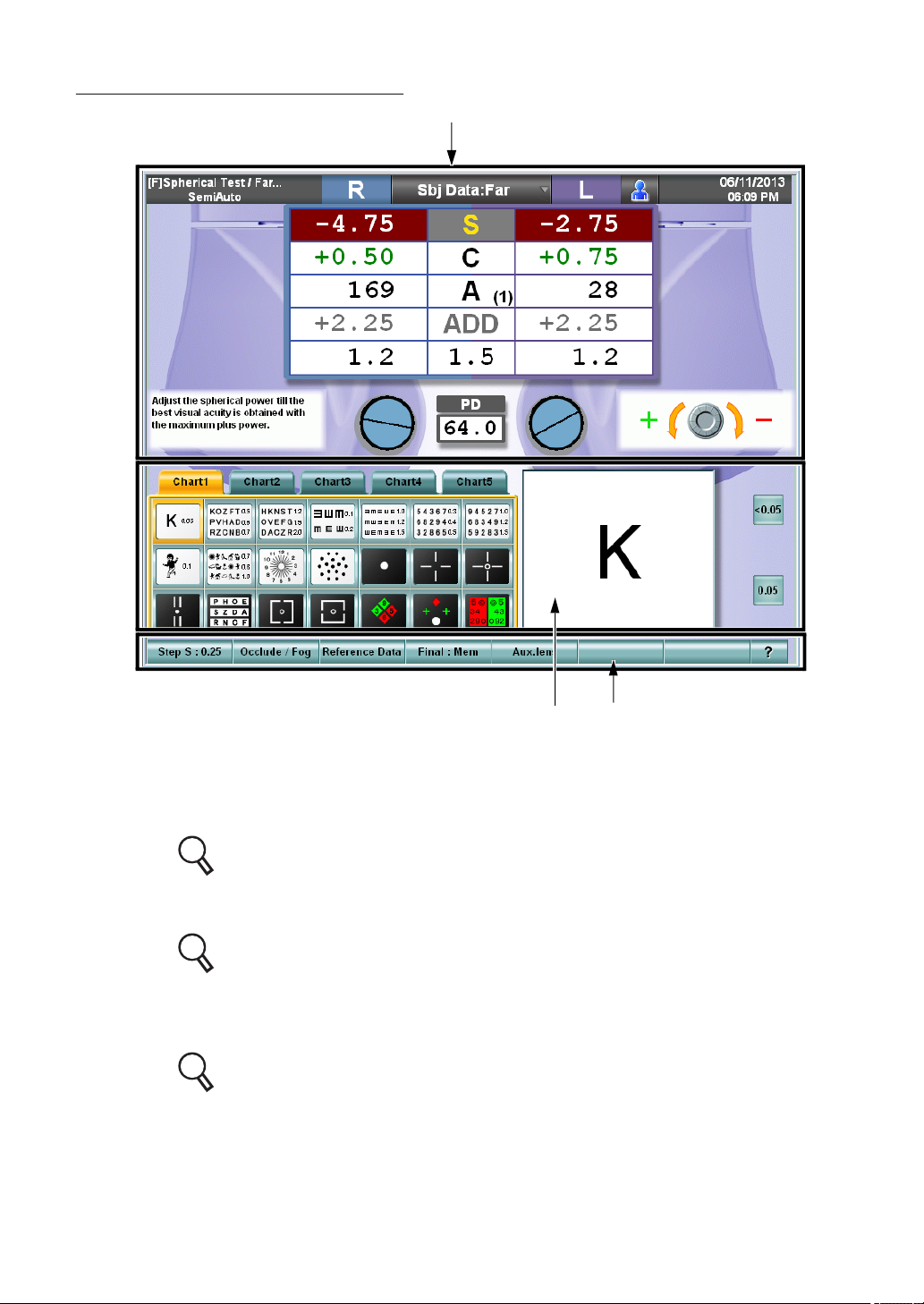
TEST SCREEN (MONITOR UNIT)
(1)
(3)(2)
(1) Data display unit
The near- and far-point data, subjective and objective data, "Mini Help", "Dial Navigation", etc. are displayed.
Refer to " DATA DISPLAY UNIT" on P.32 for details.
(2) Visual acuity chart operation unit
The chart page, the test chart icon, etc. are displayed.
Refer to " VISUAL ACUITY CHART OPERATION UNIT" on P.36 for details.
(3) Function button
The function selector buttons for the lens changing step, occlusion/fogging, etc. are
displayed.
Refer to " FUNCTION BUTTON" on P.36 for details.
31
1. BEFORE USE
Page 34
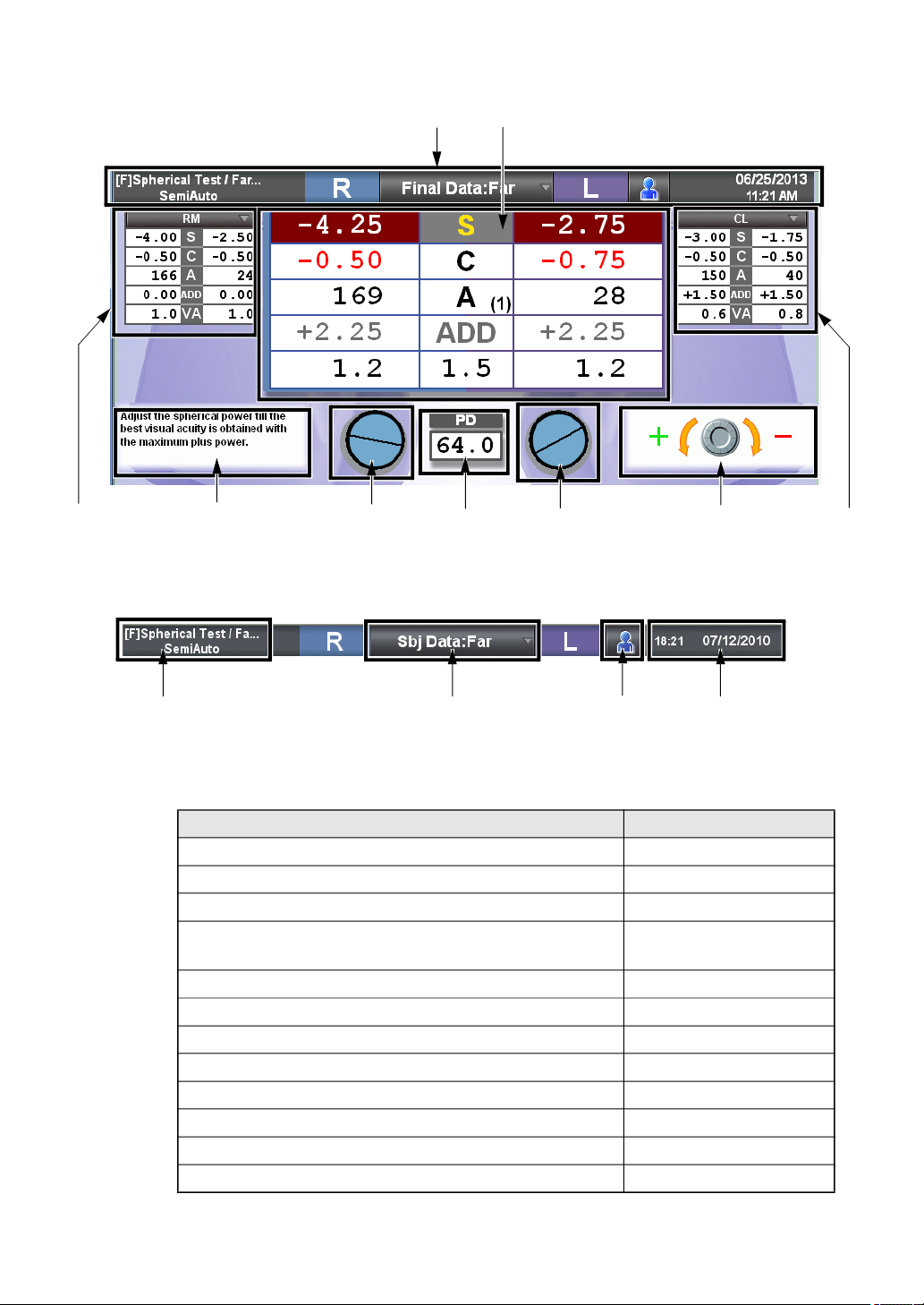
DATA DISPLAY UNIT
(1)
(2)
(3)
(4)
(1) Title bar
Displays the contents of the main data, test name, date and time.
(1)-2 (1)-1 (1)-3
(1)-1 Main data title
Displays the values in use and the far or near point test.
By pressing this tab, the list shown below will display.
Touch the desired line to select the values to be sent to the measuring head.
Value in subjective measurement (CV-5000) Subjective
Objective value measured by RM, KR, etc. RM data
Eyeglass value measured by CL CL data
The refined power for the eyeglass that is prescribed
according to the value measured subjectively
The value without the correction lens Unaided
Last prescription data registered in database Old data
The value measured in dark place Scotopic
The value under glare Glare
The value measured with the contrast chart Contrast
Data 1 stored in this instrument Memory1
Data 2 stored in this instrument Memory2
Data 3 stored in this instrument Memory3
(7) (6) (7) (5) (3)
(1)-4
Type Notation
Final data
32
1. BEFORE USE
Page 35
(1)-2 Test name
Displays the current test and program
There are two types of programs to select from:
• Custom program :Press the [Prog] button to select. The measurements can
be performed in the sequence that was programmed.
• Semi-Auto program :By touching the desired chart on the screen it will be displayed. Measurements can be performed using each
chart individually.
For the custom program, the charts can be selected and customized by pressing [Settings]
Refer to "6.3.2 CUSTOMIZE THE TEST PROCEDURE" on P.137 for customizing the program course.
For the "Semi-Auto" course, each chart can be customized by [Settings]. To
customize the "Semi-Auto" course, change the test parameters registered in the
test chart icons.
Refer to "6.3.1 CUSTOMIZING THE CHART PAGE" on P.132 for details.
(1)-3 Time and lapse of test
Displays the date, time and lapse time since the test started. Only one of them
(date or lapse time since the test started) can be displayed by [Settings].
Refer to "8.2.7 Screen settings" on P.214.
(1)-4 [Patient information] button
Edits the patient ID No./name/age.
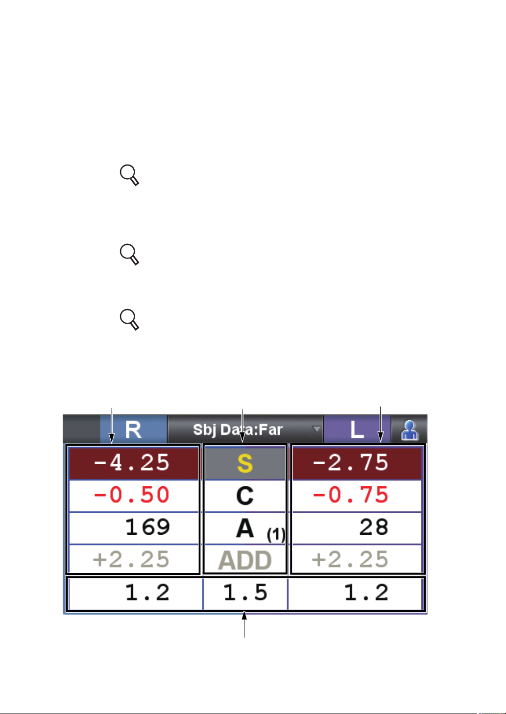
(2) Main data
Displays the data and visual acuity value set in the measuring head.
(2)-1 (2)-3
(2)-2
(2)-4
33
1. BEFORE USE
Page 36
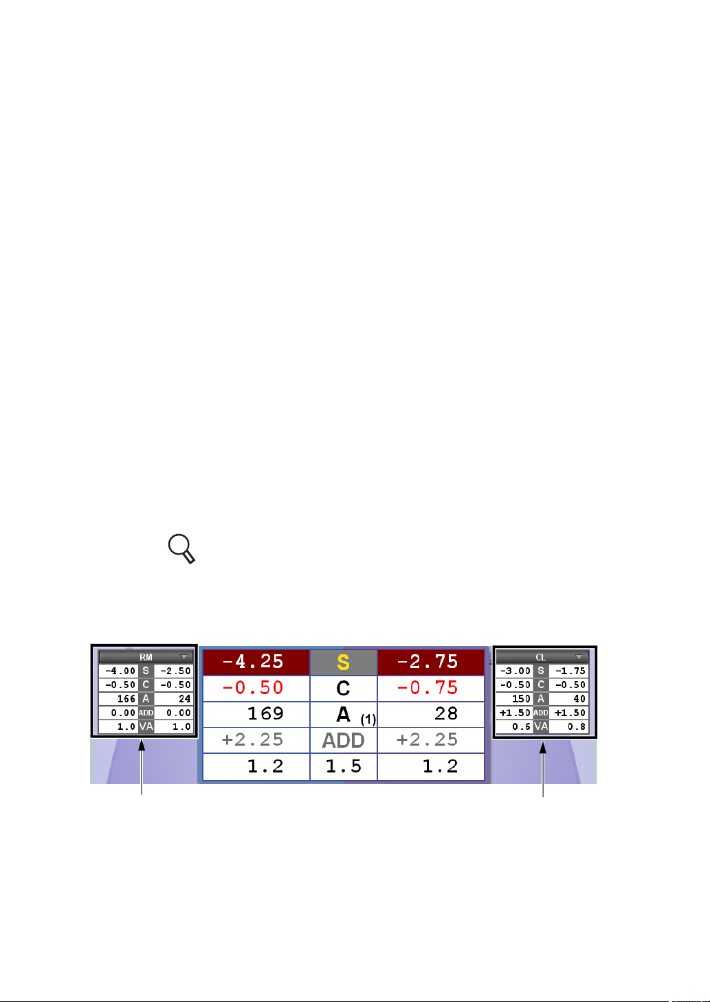
(2)-1 Right eye data
Displays the lens data, which are set for the right eye of the measuring head.
When each value is highlighted, it can be changed by turning the dial.
The colors for the values of the spherical, cylinder and addition refractive powers are changed according to the value or occluding status.
Touch each area. You can change plus/minus value of the selected data with
dial, switches, etc.
(2)-2 Left eye data
Displays the data in the same way as the right eye.
(2)-3 Data item
The data items are displayed between the right and left eye data.
The changing step quantity of the dial is displayed on [Function button].
The step quantity of axis is displayed here in ( ).
In the far-point test, the addition refractive power item is shadowed, and in the
near point test, the spherical power item is shadowed.
The shadowed item cannot be selected.
Touch each item. You can change plus/minus value of the selected item for
both eyes with dial, switches, etc.
Touch "C", and you can transpose the cylinder value to either plus or minus cylinder.
(2)-4 Visual acuity/prism
Displays the set visual acuity result or prism data.
If prism is shown by the base direction notation (XY), the refractive power of horizontal/vertical prism is displayed.
If prism is shown by the polar coordinate notation (r/), the refractive power and
angle of prism are displayed.
Refer to "8.2.7 Screen settings" on P.214 for changing the prism refractive power notation.
(3) Reference data
The objective data and lens data measured by the external devices are displayed for
comparison.
(3)-1
(3)-1 Reference data display area No.1
This data display area is used to compare or refer to data.
Touch the title being requested, and the button list for RM Data or CL Data is
displayed.
Touch the item requested and the corresponding data will be displayed accordingly.
(3)-2
34
1. BEFORE USE
Page 37

(3)-2 Reference data display area No.2
The function is the same as "Reference data display area No.1".
(4) Mini Help
Displays a simple explanation about the current test.
You can select "Displayed" or "Not displayed" by [Settings]. Refer to "8.2.7
Screen settings" on P.214 for details.
(5) Dial Navigation
Displays the dial information for the current test.
For the dial operation for each test, pictures and symbols display the proper orientation
of the dial.
The information is displayed for the correct operation for the patient to see the target
better.
You can select "Displayed" or "Not displayed" by [Settings]. Refer to "8.2.7
Screen settings" on P.214 for details.
(6) PD
Displays the PD value. When you press the [PD] switch or touch the PD value on the
test screen, it is highlighted and enables you to change it with the dial.
(7) Auxiliary lens
Displays the status of the auxiliary lens set in the measuring head, the cross cylinder
lens or TOPCON cross lens during the cylinder test. In addition, for the lens having
the axis in the open status, you can check the cylinder axis.
Touch "Aux. lens" on the test screen, and it is possible to change the occlusion.
Refer to " CHANGING THE AUXILIARY LENS" on P.118 for details.
Refer to " SELECTING THE TYPE OF OCCLUSION" on P.119 for changing
the occlusion.
35
1. BEFORE USE
Page 38
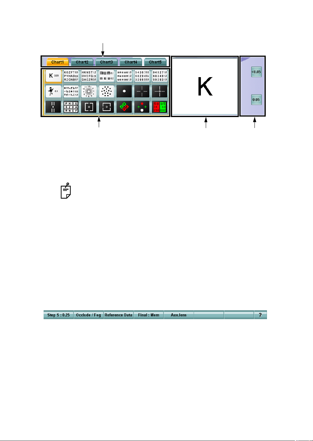
VISUAL ACUITY CHART OPERATION UNIT
(2)
(1) Chart page
Select the desired chart by touching it on the screen. The chart will display and the test
will start.
The dial mode and the auxiliary lens used in the test will be automatically positioned in
the measurement head.
While pressing the [Shift] switch, touch a test chart icon. Only the chart is
changed without changing the test.
(2) Chart page selector tab
The test chart icons can be registered for up to five pages. You can change the chart
page by touching the tab.
(3) Test chart check display
The test chart icon selected on the chart page is also displayed in another larger window once it has been selected. For the operation of the visual acuity test icon, the
character mask can be enabled by directly touching the test chart.
(4) Side button
Use these auxiliary buttons to access the necessary functions for the chart or test.
FUNCTION BUTTON
(1)
(3)
(4)
The displayed buttons are automatically changed depending on the function.
Press the [Shift] switch, and additional available functions will be displayed.
36
1. BEFORE USE
Page 39
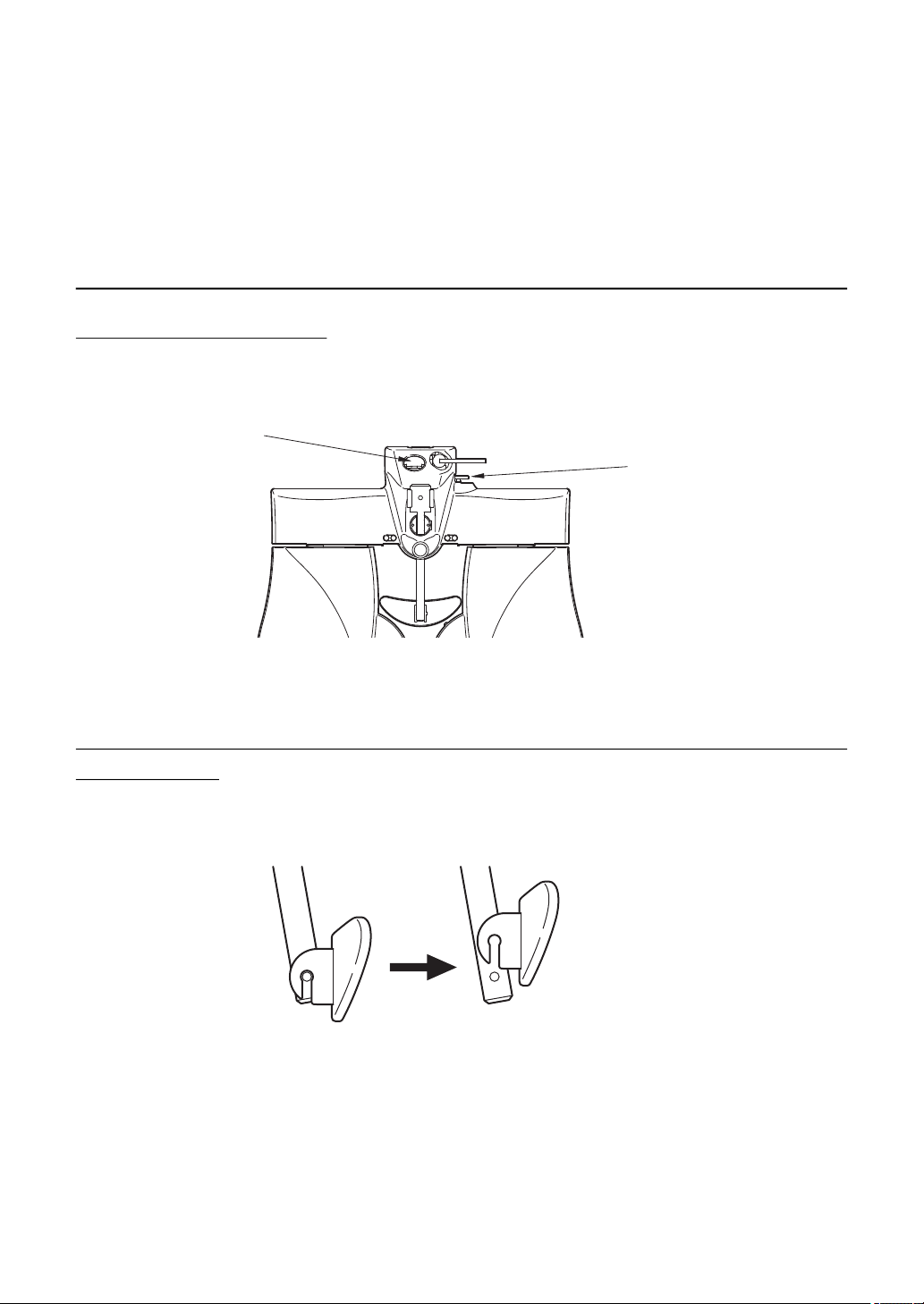
2. INSTALLATION
The service engineer must install the instrument. To make any changes or modify the connection,
contact your TOPCON dealer or the local TOPCON office listed on the back cover.
2.1 INSTALLING THE MEASURING HEAD
LEVEL ADJUSTMENT
Before using the instrument, check if it is horizontal, using the level. If the bubble is not
between the two red lines, turn the leveling knob to make the instrument horizontal.
Level
Leveling knob
INSTALLING AND REMOVING THE FACE SHIELD AND FOREHEAD REST
The face shield is attached by putting it on the face shield magnet properly.
To remove the forehead rest, when viewing from the side, pull it upward.
To mount the forehead rest, carry out the removal procedure in reverse.
37
2. INSTALLATION
Page 40
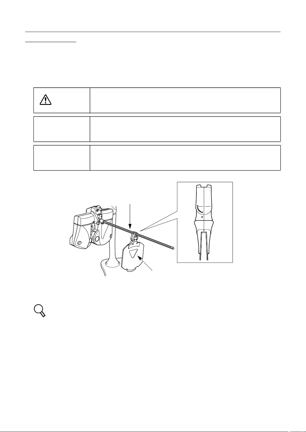
ASSEMBLY/INSTALLATION OF NEAR-POINT ROD AND NEARPOINT CARD
Insert the near-point card into the end of the near-point rod. The near-point card is designed to
slide on the near-point rod.
Insert the near-point rod into its holder and tighten the clamp screw securely. When the nearpoint rod is not in use, set it upright. (Tighten the clamp screw securely.)
CAUTION
NOTICE
NOTICE
To avoid injury due to contact, do not bring the patient’s face close to
the near-point rod.
The near-point card can be bent to only one direction. Do not bend it
forcefully in an other direction. The near-point card may be broken.
Install the near-point card to the near-point rod according to the seal,
which is adhered on the card to show its installation direction.
Near-point rod
Near-point card
Install the near-point card toward the measuring head in the direction where it can be bent.
So that the card will swing downward after placing the near-point rod in the vertical position.
For the near-point card, refer to " ADJUSTMENT OF NEAR-POINT CARD" on P.130.
38
2. INSTALLATION
Page 41
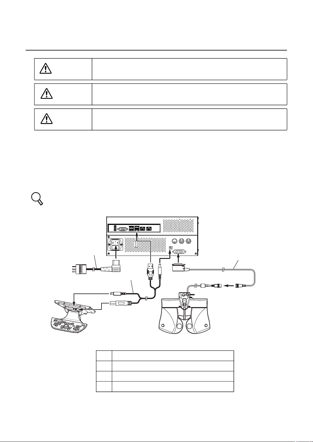
2.2 CONNECTING THE MEASURING HEAD, 1DIAL CON-
TROLLER
WARNING
CAUTION
CAUTION
This chapter will explain the procedure for connecting the measuring head and the 1Dial Controller to the power supply unit.
To avoid fire and electric shock in case of leakage, be sure to use a
grounded outlet. Do not connect to outlets that are not grounded.
To avoid electric shock, do not handle the plugs with wet fingers.
Do not to connect additional a power strip (it shall be not only in
patient environment also in outside of patient environment).
1 Make sure that the power switch of the power supply unit is OFF.
2 As shown below, connect the measuring head, the 1Dial Controller and power cord to
the power supply unit.
Refer to" Rear panel" of "1.2.2 POWER SUPPLY UNIT for CV-5000 (BUILT-IN PC TYPE)"
on P.23 for the connectors.
DC 12V
IR
ACP/MC COM3
KB
(3)
(2)
1Dial Controller
(1) Measuring head connection cable
(2) 1Dial Controller connection cable
(3) Power cord
CV
Measuring head
Item
3 Connect the power cord plug to a grounded outlet.
(1)
39
2. INSTALLATION
Page 42
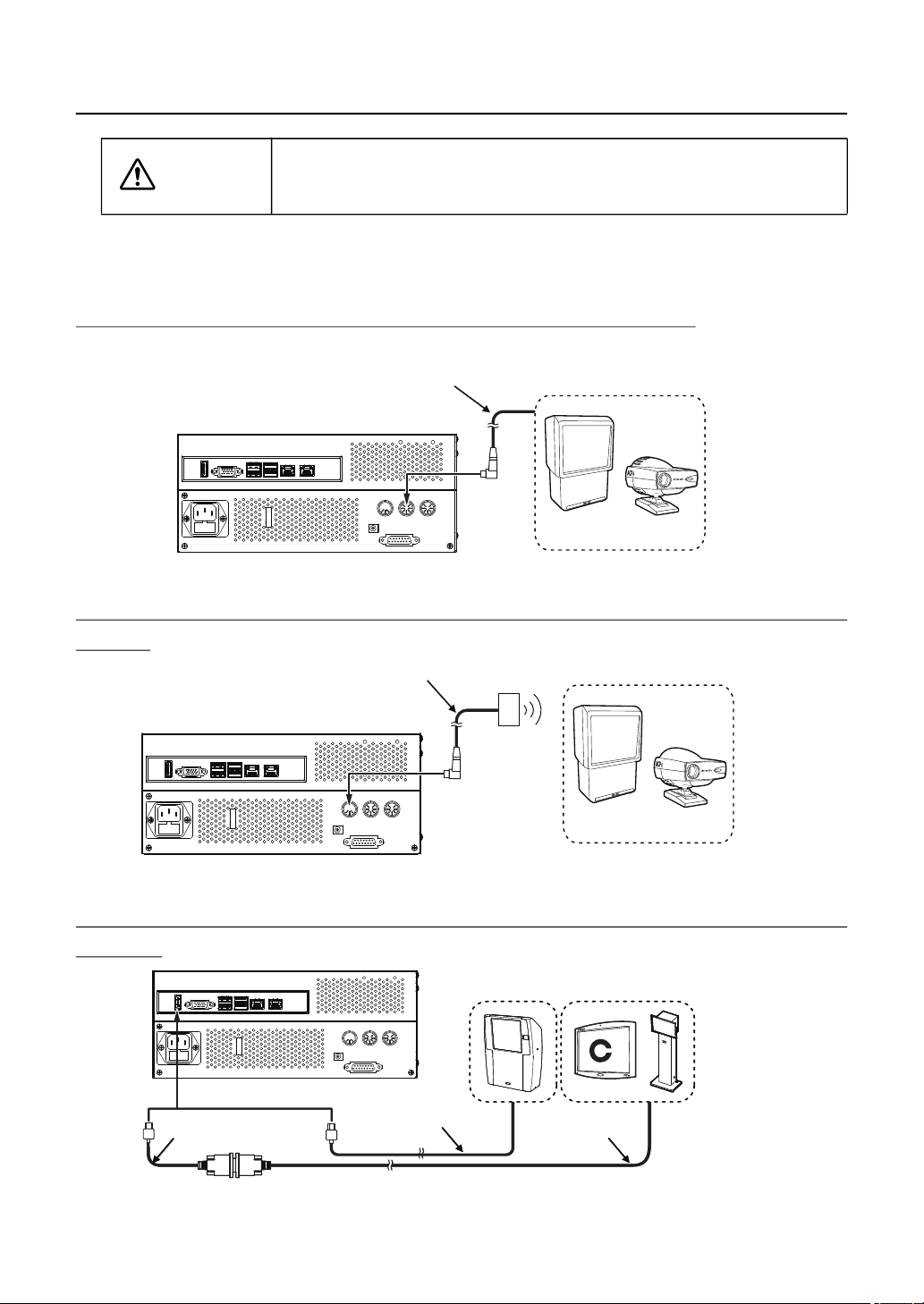
2.3 CONNECTING THE VISUAL ACUITY CHART
IR
KB
DC 12V
CV
ACP/MC COM3
Communication cable (DIN/DIN)
or
Communication cable (DIN/D-sub)
Power supply unit
Visual acuity chart (ACP-8, MC-3)
DVI cable
Visual acuity chart
HDMI DVI Change Cable
HDMI Cable
Power supply unit
Visual acuity chart
IR
KB
DC 12V
CV
ACP/MC COM3
CAUTION
Install the visual acuity chart out of the CV-5000 patient's environment.
There are three types of the methods to connect the visual acuity chart. Use the connection
method applicable to the purchased chart.
CONNECTING A DEVICE TO RS-232C (ACP-8, MC-3.)
CONNECTING A DEVICE TO INFRARED COMMUNICATION (ACP-8,
MC-3.)
Infrared communication unit
Visual acuity chart (ACP-8, MC-3)
DC 12V
ACP/MC COM3
IR
KB
CV
Power supply unit
CONNECTING A DVI / HDMI DEVICE (PC-50S, PC-50SB, MC-4S,
MC-5S)
40
2. INSTALLATION
Page 43
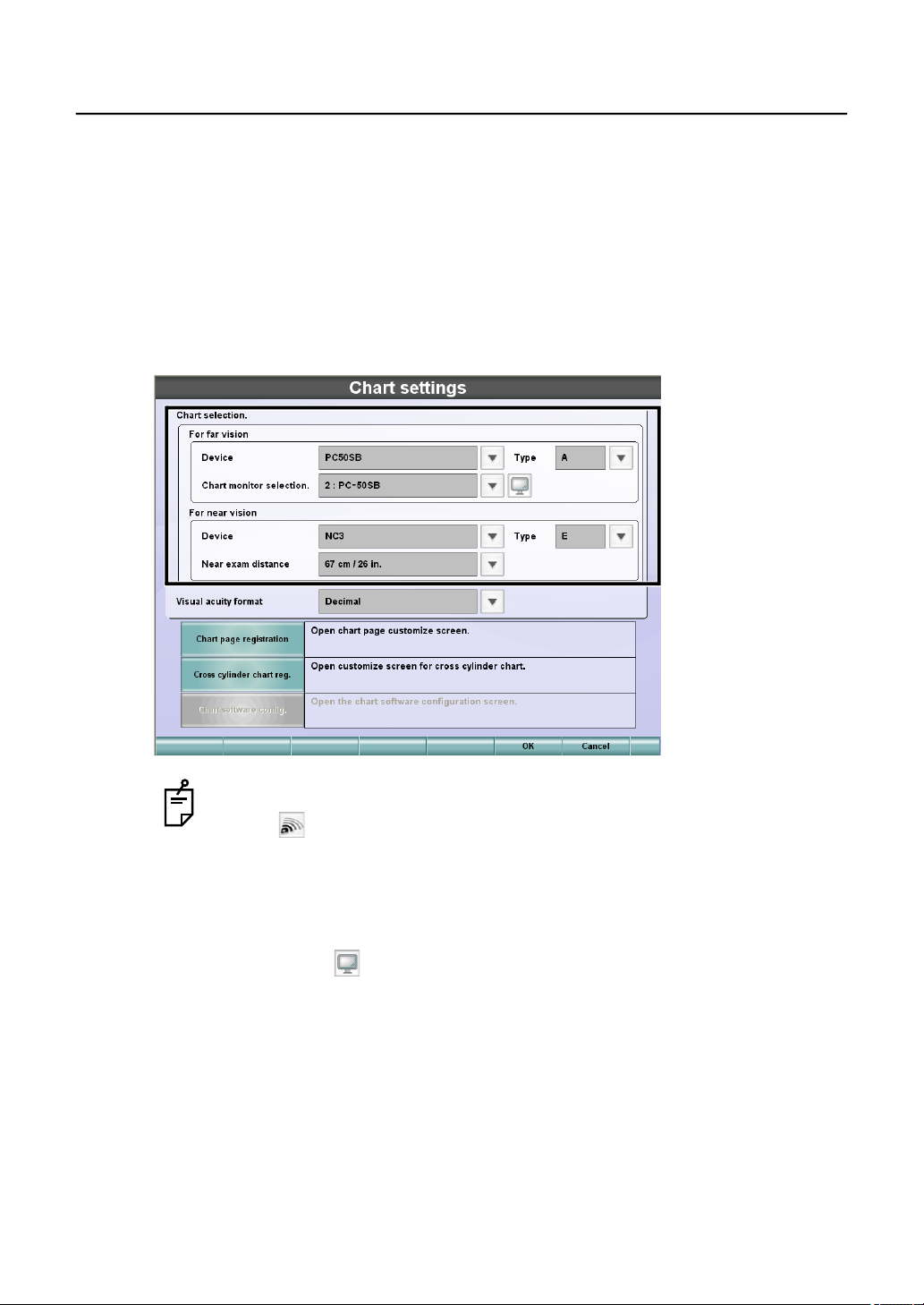
2.4 REGISTERING THE VISUAL ACUITY CHART
1 Hold down the [Shift] switch and then press the [Menu] switch on the controller unit.
The "Settings" menu is displayed.
2 Touch the [Chart settings] button.
The visual acuity chart setting screen appears.
3 Select a visual acuity chart to be connected.
Select "Device", "Type", and "Interface" of the distance visual acuity chart and "Device",
"Near exam distance" and "Type" of the near-point visual acuity chart.
When you select "Infrared communication" as the connection type and touch
the [ ] button at the right, the test signal is sent to the visual acuity chart.
This function is convenient when checking that communication can be executed correctly by the selected channel.
When you select "PC-50S", "PC-50SB" "MC-4S" or "MC-5S" from the far-
point chart devices, "Interface" is changed to "Chart monitor selection".
Touch the [ ] button at the right. You can check the monitor that corresponds to the name in the "Chart monitor selection" list being displayed.
4 Touch the [OK] button.
The "Settings" menu appears again.
41
2. INSTALLATION
Page 44
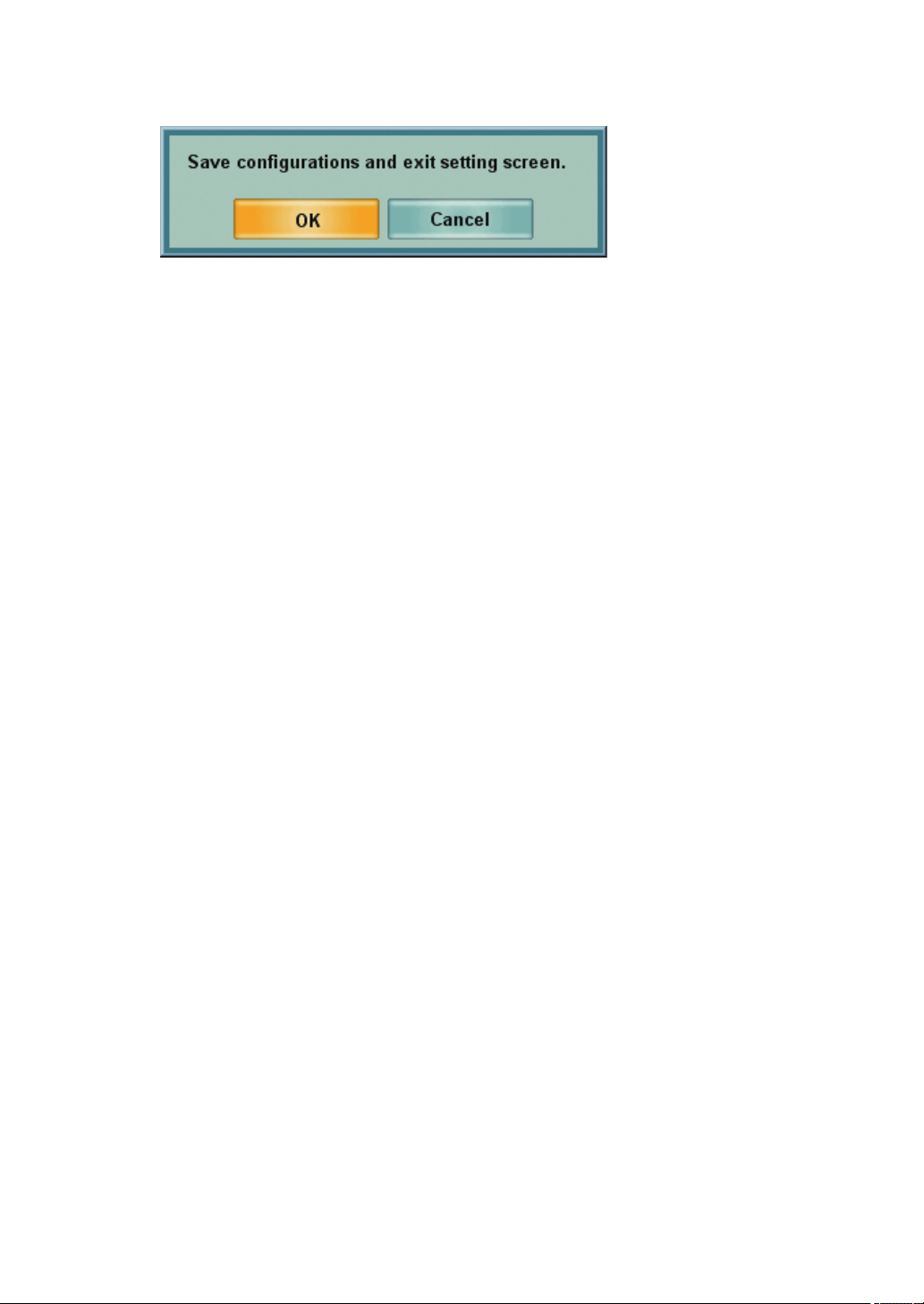
5 Touch the [Exit] button.
The check screen to finish the "Settings" menu appears.
To save the set data and finish the "Settings" menu, touch the [OK] button.
To return to the "Settings" menu without saving the set data, touch the [Cancel] button.
42
2. INSTALLATION
Page 45
3. BASIC OPERATIONS
CAUTION
To avoid electric shock, do not touch the external connection terminal
and the patient at the same time.
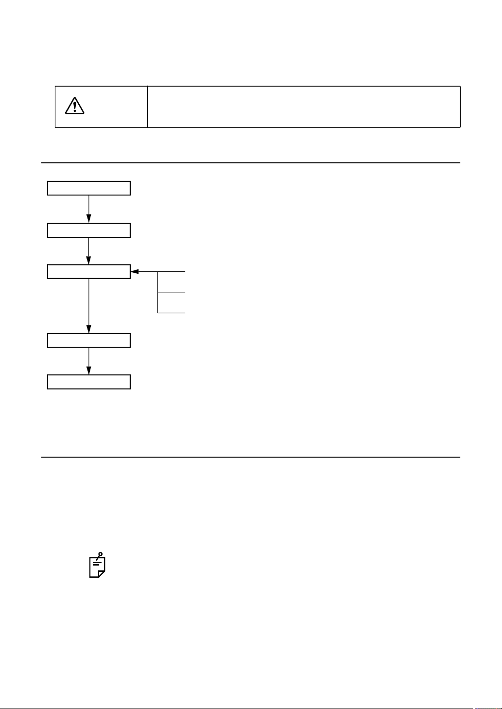
3.1 FLOW OF OPERATIONS
Turn on the power
Data input
Test
Printing
Resetting
(Refer to "3.2.1".)
(Refer to "3.2.2".)
Select the test chart and execute the test.
Select the program course and execute the test.
Select the test name and execute the test.
(Refer to "3.5".)
(Refer to "3.6".)
(Refer to "3.3".)
(Refer to "3.3".)
(Refer to "3.3".)
3.2 PREPARATION BEFORE MEASUREMENT
3.2.1 PREPARATION FOR TEST
1 Turn on the power.
Press the power switch.
When the system starts normally, the test screen appears on the monitor unit of the
1Dial Controller.
If the unit has powered up and you are ready to conduct an examination press
the [CL] swtich to clear the instrument and prepare it for the next patient.
2 Set the measuring head in front of the patient.
Wipe the forehead rest, examination window and face shield prior to placing the patient
behind the instrument.
3. BASIC OPERATIONS
43
Page 46
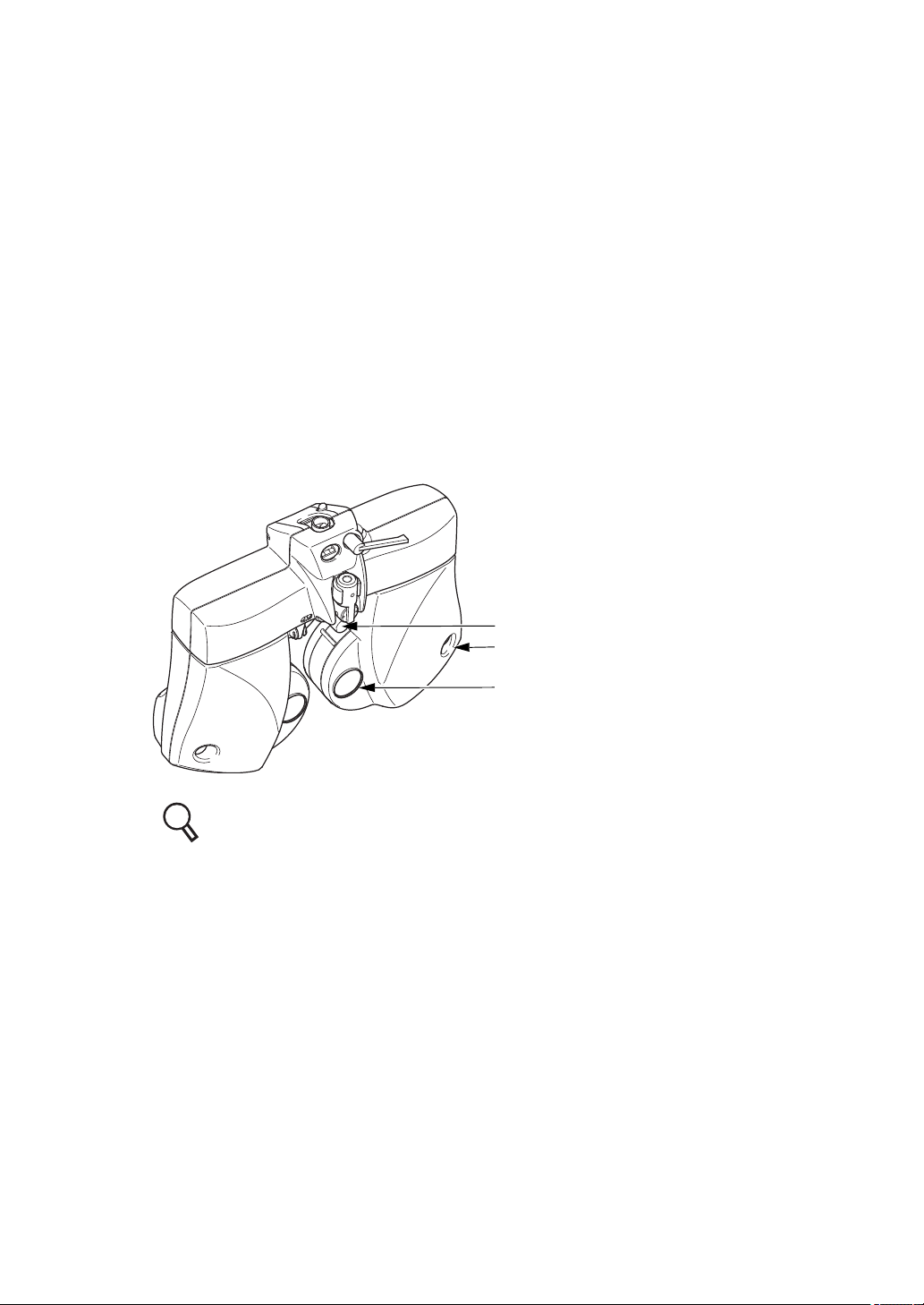
3 Press the [PD] switch.
The cornea illumination will illuminate the anterior segment of the patient.
The cross lens is set on the measuring head.
Have the patient view the far-point visual acuity chart.
4 Look into the front of the examination window from the operators side.
Turn the dial to adjust the PD so that the pupil center of the patient is aligned with the
cross center.
When the pupil center is not aligned horizontally Turn the dial to align the pupil
center with the center.
When one eye is not aligned vertically Ask the patient to move his/her face verti-
cally.
After aligning, press the [PD] switch to finish the PD adjustment.
5 Adjust the vertex distance (VD).
Look into the corneal aligning window. While watching the corneal alignment scale, turn
the forehead rest knob to adjust the distance between the patient's corneal vertex and
the lens to the desired value.
Forehead rest knob
Corneal aligning window
Examination window
Refer to "9.3 CORNEAL ALIGNING DEVICE" on P.224 for details.
44
3. BASIC OPERATIONS
Page 47
3.2.2 DATA INPUT
Input the patient's data to add it to the data list.
When TOPCON products such as RM, KR or CL are connected to the CV-5000, it is possible to read the data.
Refer to "6.1.3 IMPORTING THE DATA FROM OTHER DEVICES" on P.111 for details.
This chapter will explain how to input the measured values printed from the peripheral device
manually.
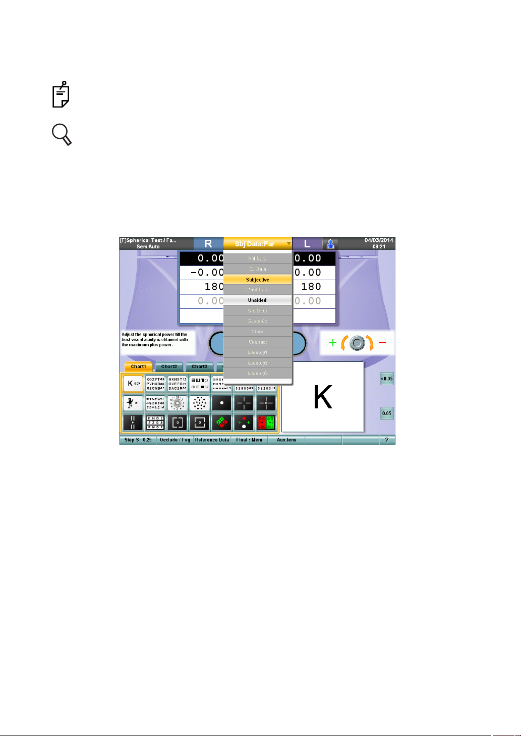
1 Touch the main data title on the test screen.
The data list (normal mode) is displayed.
45
3. BASIC OPERATIONS
Page 48
2 While press the [Shift] switch and touch the button of the data to be input in the data list.
When pressing the [Shift] switch, the data list is set in the registration mode.
Touch "Memory 1", "Memory 2" and "Memory 3" to save temporally the current
data. To save the data, input them first. Then, display the data list. While
pressing the [Shift] switch, touch the button of the data.
The data list (registration mode) displays the following data.
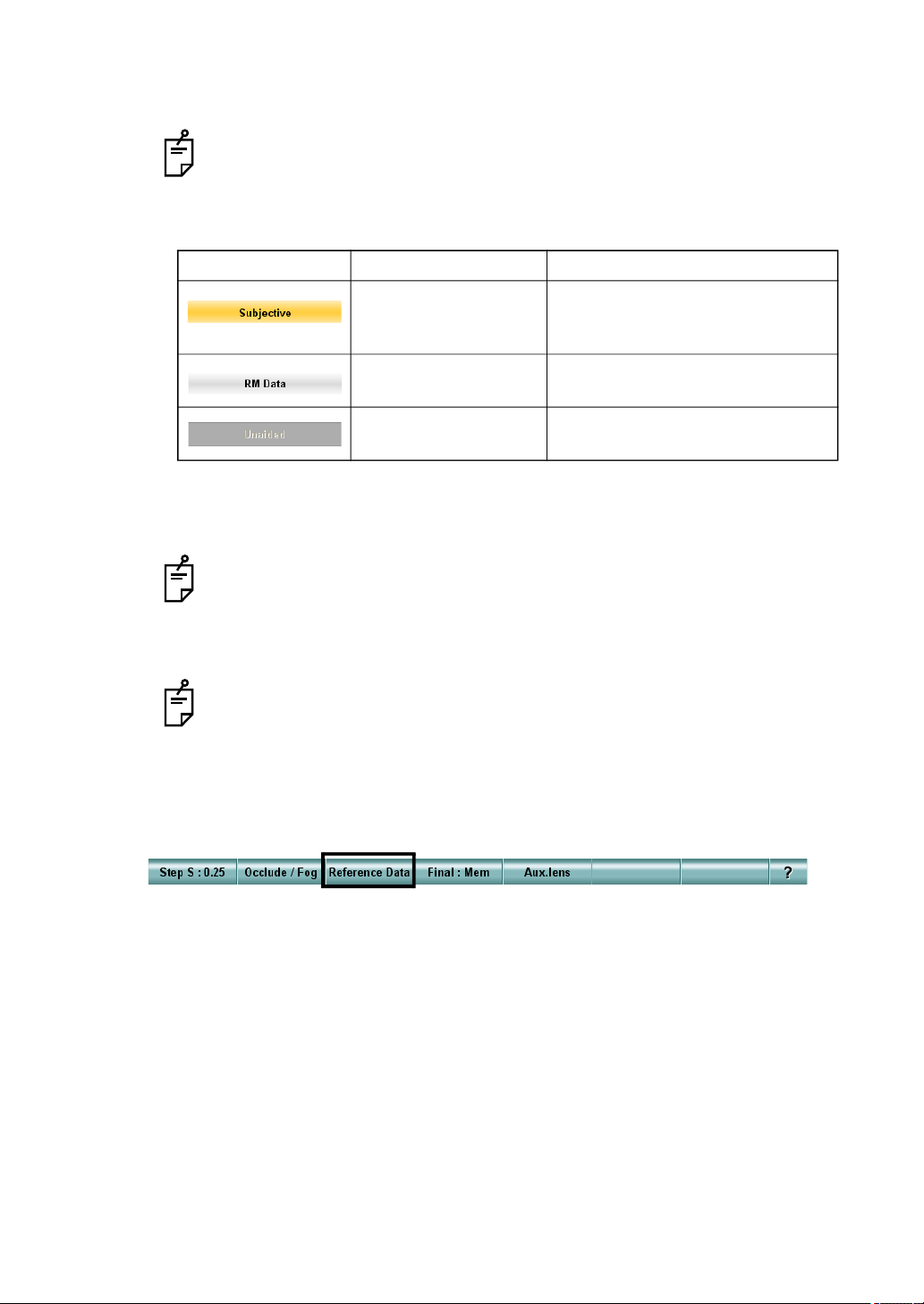
Example Meaning Operation by touching
This data is being displayed as the main
data.
This is the data being displayed.
This data can be input
and saved.
This data cannot be
saved.
This is displayed as the main data
and it is possible to input the data.
Inactive
3 Input the value obtained from the peripheral device on the test screen.
Press the switch for the data to be input on the controller unit and turn the dial to change
the value.
If you want to input other data subsequently, select the desired data from the
data list and input it.
4 Return the main data to the subjective data.
Touch the title bar and then touch the [Subjective] button in the data list.
If the subjective value is not changed after resetting, the data registered last is
copied as the subjective value.
5 Display the reference data.
If the reference data is not displayed on the screen, touch the [Reference Data] button
from the function buttons.
The input data is displayed on the reference data display area.
46
3. BASIC OPERATIONS
Page 49
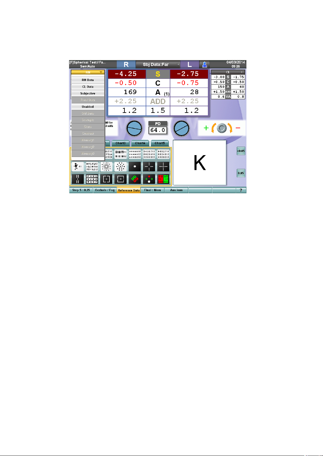
6 Exchange the reference data.
Touch the title bar of the reference data display area. Then, touch the desired data in the
data list.
The selected data is displayed on the reference data display area.
47
3. BASIC OPERATIONS
Page 50
3.3 TEST
Execute the test applicable to the patient.
SELECT THE TEST CHART AND EXECUTE THE TEST.
Select the test chart icon on the chart page and execute the test.
Touch the test chart icon. The selected chart is displayed on the test chart check display area
and the test relevant to the icon starts.
The data, patient's eye and the auxiliary lens to be used in the test are automatically set.
When you select a test chart to execute the test, you can easily change the test order.
Arrange the test chart icons in the desired order from the upper left to the right and select them
in a left-to-right sequence. So, you can execute the tests in the desired order.
Refer to "6.3.1 CUSTOMIZING THE CHART PAGE" on P.132 for details.
SELECT THE PROGRAM COURSE AND EXECUTE THE TEST.
Register the test sequence and save it as a course. The tests are executed in the registered
order.
Even if you are in the program course, you can randomly execute another test, which is
not included in the course, by touching the test chart icon on the chart page. In this case,
press the [SET] switch to restore the system to the original step in the program course.
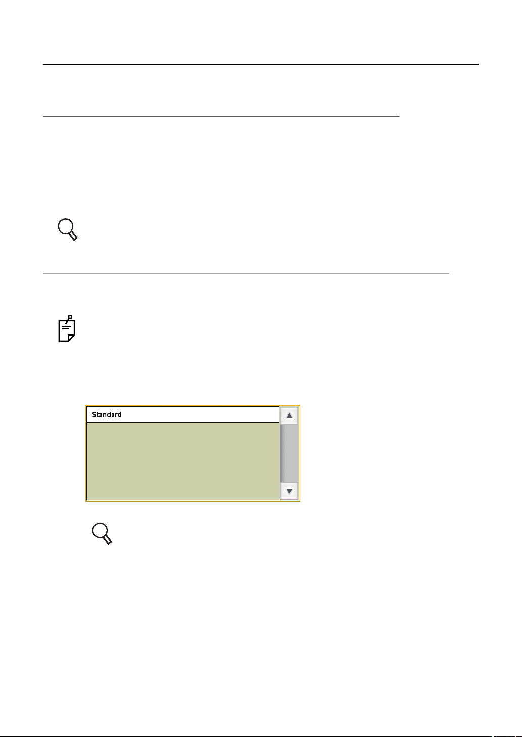
1 Press the [Prog] switch.
The course selection window is displayed on the screen.
You can select the course registered by [Course registrations] on the "Settings" menu.
Refer to "6.3.2 CUSTOMIZE THE TEST PROCEDURE" on P.137 for [Course
registrations].
2 Touch the course name or turn the dial to highlight/select a course. Then, press the
[SET] switch at the center of the dial.
3 Execute the test.
The first test step registered in the selected course is executed.
To advance to the next test, press the [SET] switch at the center of the dial.
Press the [SET] switch while pressing the [Shift] switch, and the system returns to the
previous test.
48
3. BASIC OPERATIONS
Page 51
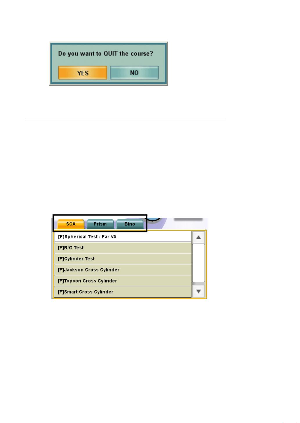
4 When the last test of the program course has been completed, the following message is
displayed.
To finish the program course, touch the [YES] button.
SELECT THE TEST NAME AND EXECUTE THE TEST.
The specified test starts.
1 Press the [Shift] and [Prog] switches simultaneously.
The test name selection window is displayed on the screen.
The test names are classified into three groups, [SCA], [Prism] and [Bino].
The test names can be selected by touching the tab.
• SCA :Includes the tests to correct the spherical refraction, cylinder refraction and
binocular balance.
• Prism :Includes the phoria tests.
• Bino :Includes the binocular function tests excluding the phoria tests.
The displays of far- and near-point tests are changed by pressing the [F/N] switch on the
controller unit.
2 Touch the test name or turn the dial to select a test. Then, press the [SET] switch at the
center of the dial.
49
3. BASIC OPERATIONS
Page 52
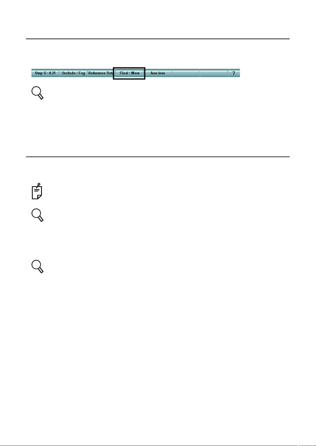
3.4 PRESCRIPTION
Touch the [Final: Mem] button from the function buttons to copy the subjective data to the Final
data and then modify the data if desired.
Refer to " RECORDING AND DISPLAYING THE PRESCRIPTION DATA" on P.127 for
setting the prescription data.
After setting the Final data, adjust the power for the final prescription.
3.5 OUTPUTTING THE RESULT
To print the test results through the thermal printer built in the power supply unit, press the [Print]
switch.
The unmeasured items are not output or printed.
Refer to "6.4.1 DATA TO BE PRINTED" on P.140 for the output data.
In addition to the printing function, you can assign the following functions to the [Print] switch:
Function to output the data through serial communication;
Function to output the file data.
Refer to "8.2.2 Function settings" on P.192 for details of the setting method.
50
3. BASIC OPERATIONS
Page 53

3.6 RESETTING
After the test has been completed, press the [CL] switch.
The test screen, test chart and the measuring head are cleared and re-initialized. The system is
ready to conduct an examination for the next patient.
When further testing is not required, press the power switch to turn off the system.
51
3. BASIC OPERATIONS
Page 54

4. GENERAL OPTOMETRY PROCE-
DURE
By making use of the measured values of RM or CL, you can perform an accurate subjective
refractive power measurement efficiently.
This section will explain the flow of the typical subjective refractive power measurement (far-point/
near-point) and the binocular (far-point phoria/near-point phoria) measurement.
4.1 DATA INPUT
Input the measured data of other devices manually or capture them automatically.
Refer to "3.2.2 DATA INPUT" on P.45 for manual input.
Refer to "6.1.3 IMPORTING THE DATA FROM OTHER DEVICES" on P.111 for auto-
matic capture.
4.2 FAR-POINT REFRACTIVE POWER MEASUREMENT
REFRACTIVE POWER MEASUREMENT BY USING CROSS CYLINDER
Press the [Prog] switch on the controller unit, and the list is displayed. The test sequence of
the "Standard" course on the list is shown below. The tests for "Checking the corrected visual
acuity" are done with the order of "Right eye - Left eye". "Binocular balance test" and after are
done with both eyes.
(1) Checking the spherical power: R/G test .........................Refer to P.56.
(2) CC test (Cylinder axis/Cylinder power)............................Refer to P.59, P.61 and P.62.
(3) Checking the spherical power: R/G test .........................Refer to P.56.
(4) Checking the corrected visual acuity ..............................Refer to P.55.
(5) Binocular balance test ....................................................Refer to P.64, P.65 and P.66.
(6) Checking prescription visual acuity/prescription power .. Refer to P.127
52
4. GENERAL OPTOMETRY PROCEDURE
Page 55
REFRACTIVE POWER MEASUREMENT USING ASTIGMATISM
TEST CHART
Clear the cylinder power and set only the spherical power in advance.
(1) Astigmatism chart test (Cylinder axis/Cylinder power) ....Refer to P.57.
(2) Checking the spherical power: R/G test .........................Refer to P.56.
(3) Checking the corrected visual acuity ..............................Refer to P.55.
(4) Binocular balance test ....................................................Refer to P.64, P.65 and P.66.
(5) Checking prescription visual acuity/prescription power .. Refer to P.127.
4.3 NEAR-POINT REFRACTIVE POWER MEASUREMENT
Press the [Prog] switch on the controller unit, and the list is displayed. The test sequence of the
"Standard" course on the list is shown below.
Prior to the near tests, conduct the far-point refractive power measurement.
(1) Binocular ADD measurement with cross grid ............Refer to P.95.
(2) Checking the near-point visual acuity ........................Refer to P.55
53
4. GENERAL OPTOMETRY PROCEDURE
Page 56

4.4 BINOCULAR MEASUREMENT
FAR-POINT PHORIA
Start the test by using the result of the far-point refractive power refinement.
(1) Far-point vertical phoria measurement (Polarization cross test/Cross ring test/Prism
separation method) ...........Refer to P.68, P.70 and P.71.
(2) Far-point horizontal phoria measurement (Polarization cross test/Cross ring test/Prism
separation method) ...........Refer to P.68, P.70 and P.74.
(3) Refining the necessary prism power with the Sheard's criteria ...... Refer to P.93.
NEAR-POINT PHORIA
Start the test by using the result of the near-point refractive power refinement.
(1) Near-point vertical phoria measurement (Prism separation method) Refer to P.71.
(2) Near-point horizontal phoria measurement (Prism separation method) .. Refer to P.74.
(3) Refining the necessary prism power with the Sheard's criteria ..... Refer to P.93.
54
4. GENERAL OPTOMETRY PROCEDURE
Page 57
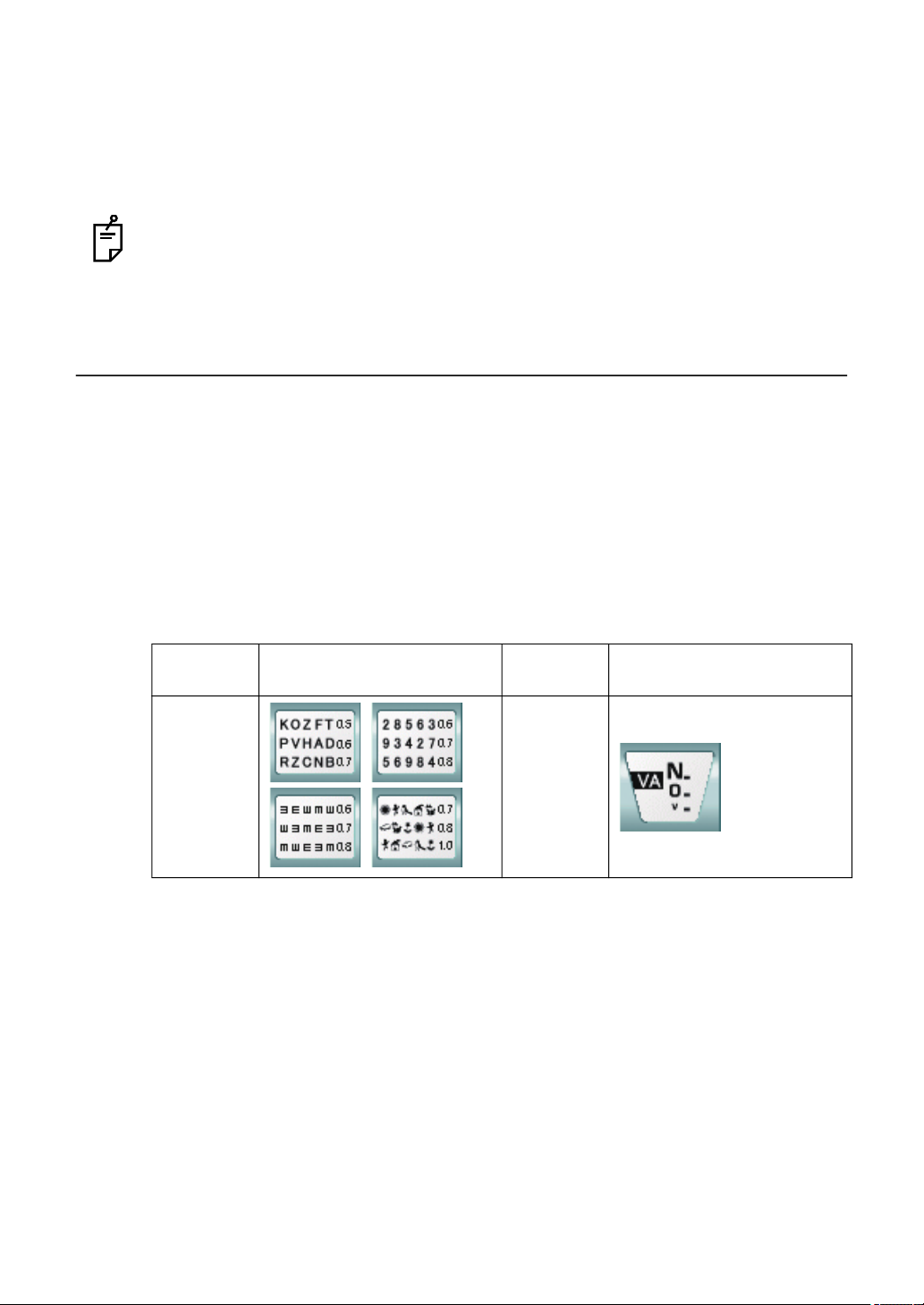
5. OPERATION FOR TESTS
This chapter will explain the tests and operations that can be performed with the CV-5000 instrument.
This manual will explain the operation when the ACP-8 (A) is used as the far-point chart
and NC-3 (E), as the near-point chart in the test.
5.1 VISUAL ACUITY TEST/SPHERICAL POWER/CYLIN-
DER POWER CORRECTION
5.1.1 VISUAL ACUITY MEASUREMENT
Measure the patient's visual acuity.
1 Select a visual acuity chart.
To perform the visual acuity measurement, select the visual acuity chart icon from the
chart page.
In near-point test, select a proper target from the near-point card targets manually.
Example of the test chart icons on chart page
Far-point
chart
ACP-8(A) NC-3(E)
Far-point test chart icon Near-point
chart
Near-point test chart icon
55
5. OPERATION FOR TESTS
Page 58
The following items are automatically changed as shown below.
Item Description
The test is perfomed with rigth eye, left eye or both eyes.
Test eye
Auxiliary lens Not set.
Dial operation mode
Dial Navigation
When the test chart is selected, the status of last test is succeeded.
In far-point test, the mode to operate the spherical power is
set.
In near-point test, the mode to operate ADD is set.
2 Measure the visual acuity.
Measure the patient's visual acuity.
To display the visual acuity test chart having the different visual acuity values in far-point
test, select a test chart again on the chart page or press [] and [] among the [Move]
switches on the controller unit. In near-point test, rotate the near-point card targets to
select a corresponding acuity chart.
3 Record the visual acuity value.
Touch the button applicable to the patient's visual acuity among the side buttons. The
value is recorded as the patient's visual acuity.
Each time you touch the visual acuity button, the recorded value is overwritten for correction purposes.
For the visual acuity value button, refer to " SETTING THE VISUAL ACUITY
VALUE DIRECTLY" on P.120.
5.1.2 R/G TEST
Measure the spherical refraction for the patient.
1 Fog the patient's eye.
To make use of the fogging method, turn the dial counterclockwise to shift the spherical
power to the plus side in the amount of fogging power desired.
It is possible to preset the fogging quantity when the R/G test chart is selected.
Set the fogging quantity on the parameter setting screen. To access the parameter setting screen, select "Settings", "Chart settings", "Chart page registration"
and touch the [Modify] button.
56
5. OPERATION FOR TESTS
Page 59
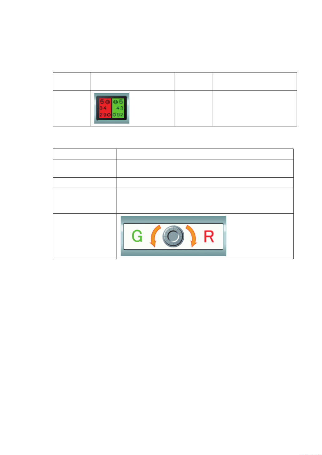
2 Select the R/G test chart.
To perform the R/G test, select the R/G test chart icon on the chart page.
In near-point test, set a proper target from the near-point card targets manually.
Example of the test chart icons on chart page
Far-point
chart
ACP-8(A) NC-3(E) -
The following items are automatically changed as shown below.
Item Description
Test eye
Auxiliary lens Not set.
Dial operation mode
Dial Navigation
Far-point test chart icon Near-point
chart
The test is performed with right eye, left eye and both eyes.
When the test chart is set, the last status is succeeded.
In far-point test, the mode to operate the spherical power is
set.
In near-point test, the mode to operate ADD is set.
Near-point test chart icon
3 Correct the spherical power.
Ask the patient which side the characters are seen better, on the red or green side.
When the characters on the red side are seen better, turn the dial in the "R" direction of
"Dial Navigation". When those on the green side are seen better, turn the dial in the "G"
direction.
Adjust until the characters on both sides are seen equally.
5.1.3 ASTIGMATISM TEST
Search for the approximate astigmatic correction value of the patient.
1 Prepare for the test.
Before beginning this test, carry out the following operation:
Set the cylinder axis "180" and cylinder power "0.00". Perform fogging in the plus direction and then shift the power in the minus direction. Adjust the spherical power to the
lowest so that the visual acuity may be 0.5 to 0.6 (20/40 to 20/30, 6/18 to 6/9).
57
5. OPERATION FOR TESTS
Page 60
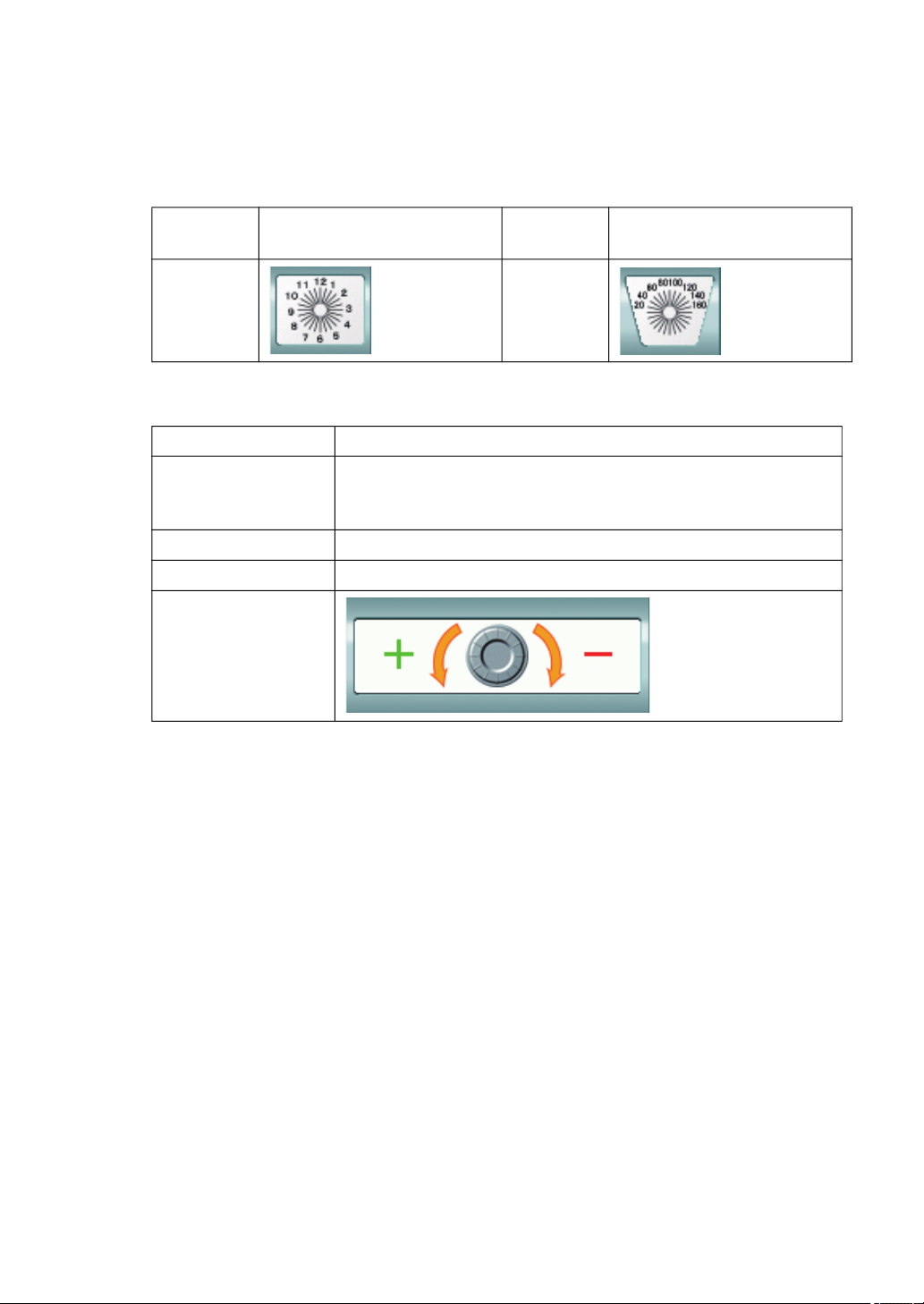
2 Select the astigmatism test chart.
To perform the astigmatism test, select the astigmatism test chart icon on the chart page.
In the near-point test, select the proper target from the near-point card targets manually.
Example of the test chart icons on chart page
Far-point
chart
ACP-8(A) NC-3(E)
The following items are automatically changed as shown below.
Item Description
Test eye
Auxiliary lens Not set.
Dial operation mode The mode to operate the cylinder axis is set.
Dial Navigation
Far-point test chart icon Near-point
chart
When any other item except "binocular" is the last test object,
the status of last test is succeeded. When "binocular" are the
last test object, the right eye of the patient is selected.
Near-point test chart icon
3 Correct the cylinder axis.
If the dial operation mode is not set for "Cylinder axis", press the [A] switch on the controller unit to change the mode.
Ask the patient whether he/she sees a darker bolder line than others. If there is no such
line, the patient does not have astigmatism. If he/she sees a darker bolder line, have
him/her answer with the numerals between 1 and 6. Turn the dial to set "The numeral of
the answer x 30" to the cylinder axis. The cylinder axis is changed to the positive direction by turning the dial in the "+" direction and, to the negative direction by turning it in
the "-" direction.
4 Correct the cylinder power.
Press the [C] switch on the controller unit to change the dial operation mode to "Cylinder
power".
Change the cylinder power until all the lines are seen with equal clarity. The cylinder
power is changed to the positive direction by turning the dial in the "+" direction and, to
the negative direction by turning it in the "-" direction.
58
5. OPERATION FOR TESTS
Page 61
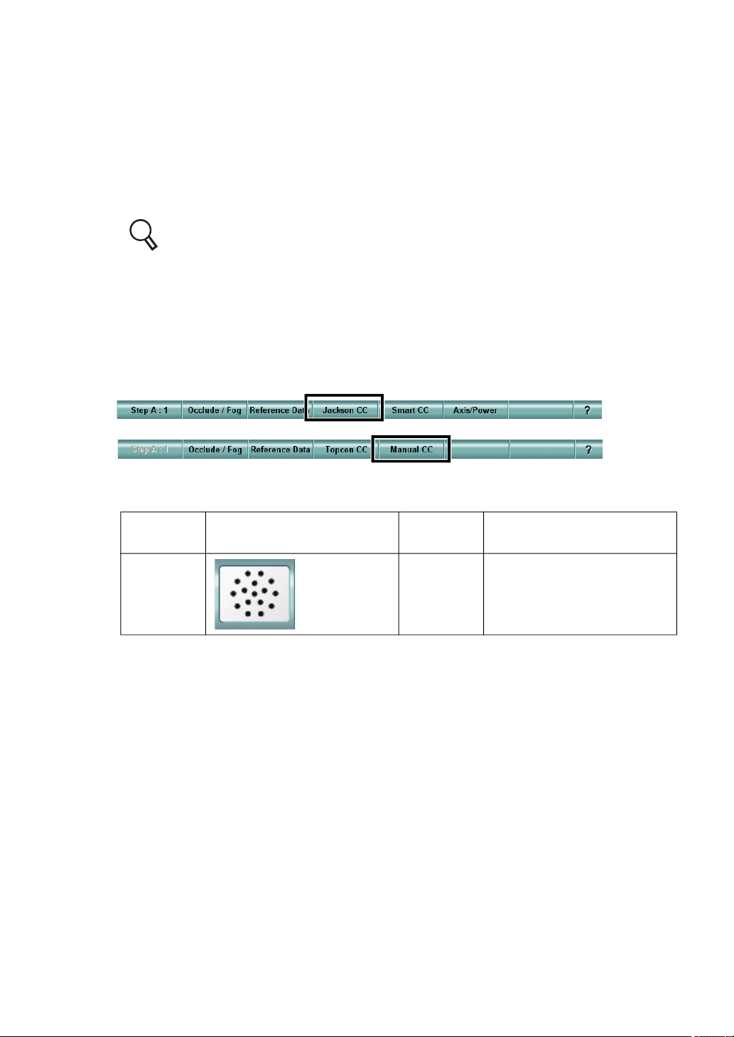
5.1.4 CROSS CYLINDER TEST (JACKSON CROSS)
Measure the patient's astigmatism accurately by using the Jackson cross cylinder lens.
1 Prepare for the test.
Before beginning this test, adjust the spherical power so that the characters on the red
and green sides are seen equally in the R/G test. Additionally, set the cylinder power/
axis measured objectively or execute the astigmatism test to set the approximate cylinder power/axis.
For the R/G test, refer to "5.1.2 R/G TEST" on P.56.
For the astigmatism test, refer to "5.1.3 ASTIGMATISM TEST" on P.57.
2 Select the cross cylinder test chart.
To perform the cross cylinder (Jackson cross) test, select the cross cylinder test chart
icon on the chart page.
After selecting the test chart, if the test name is not "[F] Jackson Cross Cylinder" at the
upper left on the screen, touch the [Jackson CC] button or [Manual CC] button from the
function buttons.
Example of the test chart icons on chart page
Far-point
chart
ACP-8(A) NC-3(E) -
Far-point test chart icon Near-point
chart
Near-point test chart icon
59
5. OPERATION FOR TESTS
Page 62
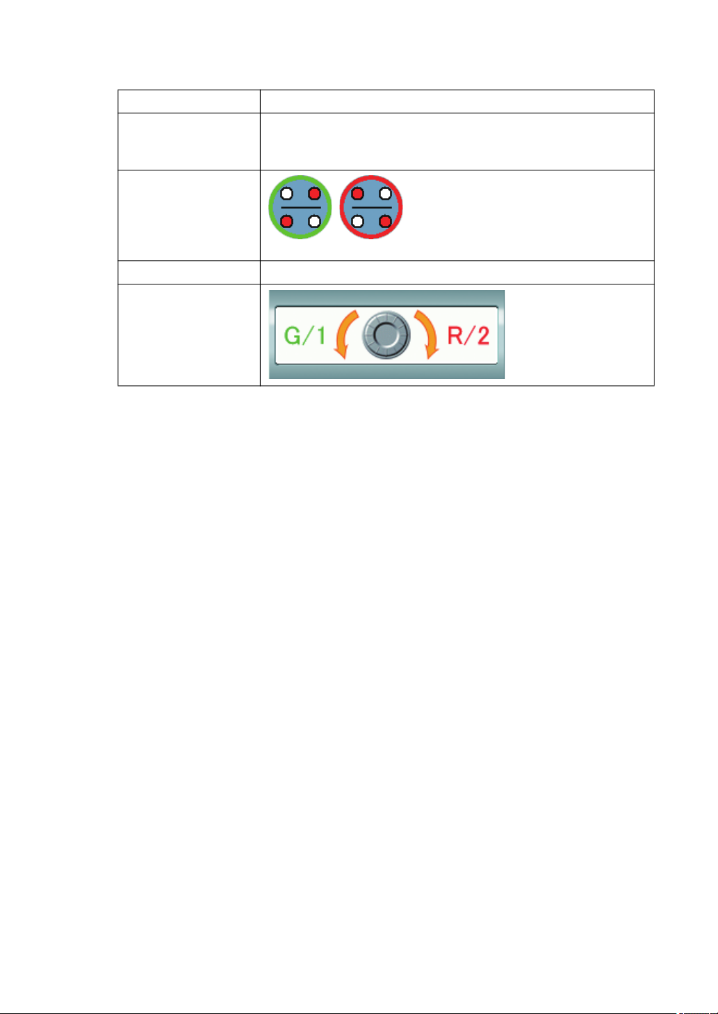
The following items are automatically changed as shown below.
Item Description
When any other item except "binocular" is the last test object,
Test eye
Auxiliary lens
Dial operation mode The mode to operate the cylinder axis is set.
Dial Navigation
the status of last test is succeeded. When "binocular" are the
last test object, the right eye of the patient is selected.
The Jackson cross cylinder lens is
selected for the eye being tested.
The green and red frames around the
lens indicate the front and rear of the
cross cylinder.
3 Measure the cylinder axis.
Press the [1] and [2] switches on the controller unit alternately and repeatedly. Have the
patient answer which frame he/she can see the chart better, on the red or green side.
When the chart is seen better with the green frame, turn the dial in the "G/1" direction of
"Dial Navigation". When the chart is seen better with the red frame, turn the dial in the
"R/2" direction.
Make adjustments until the patient sees the chart almost equally with both red and green
frames.
4 Measure the cylinder power.
After measuring the cylinder axis, proceed to the cylinder power measurement.
To proceed to this measurement, press the [C] switch on the controller unit.
The procedure is the same as the cylinder axis measurement. Make adjustments until
the patient sees the chart almost equally through the CC lens having red or green frame.
Press the [A] switch on the controller unit. The system returns to the cylinder axis measurement mode.
60
5. OPERATION FOR TESTS
Page 63

5.1.5 CROSS CYLINDER TEST (TOPCON CROSS)
Measure the patient's astigmatism accurately by using the TOPCON cross
cylinder lens. The TOPCON cross cylinder lens is made so that the front
and rear of the Jackson cross cylinder lens can be viewed at the same time.
By seeing the green and red in the periphery around the lens, you can check
the views of the front and rear at the same time.
1 Prepare for the test.
Before beginning this test, adjust the spherical power so that the characters on the red
and green sides may be seen equally in the R/G test. Additionally, set the cylinder
power/axis measured objectively or execute the astigmatism test to set the approximate
cylinder power/axis.
For the R/G test, refer to "5.1.2 R/G TEST" on P.56.
For the astigmatism test, refer to "5.1.3 ASTIGMATISM TEST" on P.57.
2 Select the cross cylinder test chart.
To perform the cross cylinder (TOPCON cross) test, select the cross cylinder test chart
icon on the chart page. Then, touch the [Topcon CC] button from the function buttons.
Example of the test chart icons on chart page
Far-point
chart
ACP-8(A) NC-3(E) -
The following items are automatically changed as shown below.
Item Description
Test eye
Auxiliary lens
Dial operation mode The mode to operate the cylinder axis is set.
Dial Navigation
Far-point test chart icon Near-point
chart
When any other item except "binocular" is the last test object,
the last status is succeeded. When "binocular" are the last
test object, the right eye of the patient is selected.
The TOPCON cross cylinder lens is set to the
test eye.
Near-point test chart icon
61
5. OPERATION FOR TESTS
Page 64
3 Measure the cylinder axis.
Have the patient answer which frame side on the CC lens he/she can see better, on the
red or green side.
When the green frame side is seen better, turn the dial in the "G" direction of "Dial Navigation". When the red frame side is seen better, turn the dial in the "R" direction.
Make adjustment until the patient sees the green and red frame sections almost equally.
4 Measure the cylinder power.
After measuring the cylinder axis, proceed to the cylinder power measurement.
To proceed to this measurement, press the [C] switch on the controller unit.
The procedure is the same as the cylinder axis measurement. Make adjustment until
the patient sees chart almost equally through the CC lens having red and green frames.
Press the [A] switch on the controller unit. The system returns to the cylinder axis measurement.
5.1.6 SMART CROSS TEST
Measure astigmatism accurately with the Jackson cross cylinder lens semi-automatically.
In general, the cross cylinder test forces the patient to compare
the targets having slightly different powers repeatedly. Consequently the patient becomes tired from stress.
In the smart cross test, the cylinder power and axis, which are
input as the initial values, are regarded as the "Temporary-real
values". By referring to the temporary-real axis value, the system calculates the axis whose view is most different on the front
and rear of the cross cylinder lens. First, the patient's comparison begins with this calculated axis. Then, the axis is moved to
the opposite side against the temporary real value and the system asks the patient to compare the views of the chart. The
axis movement is automatically conducted. As the move width
is made smaller, the system searches for the "Real cylinder
axis". This test is performed to reduce the fatigue on the
patient.
At the final stage of the axis test, the type of the used cross cylinder lens is automatically changed from "0.50D" to "0.25D"
to reduce uneasiness of the patient. The test finishes with a
lower cross-cylinder power resulting in a clearer end result and
less fatigue for the patient.
1 Prepare for the test.
In some cases, measurement cannot be done. Before beginning the test, set the cylinder power and axis measured objectively.
(Temporary-real value)
Image of the cylinder axis
move during test
62
5. OPERATION FOR TESTS
Page 65
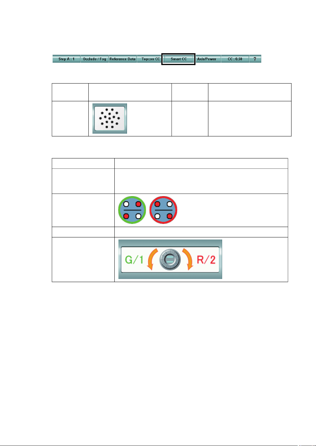
2 Select the cross cylinder test chart.
Select the cross cylinder test chart icon on the chart page. Then, touch the [Smart CC]
button from the function buttons.
Example of the test chart icons on chart page
Far-point
chart
ACP-8(A) NC-3(E) -
The following items are automatically changed as shown below.
Item Description
Test eye
Auxiliary lens
Dial operation mode The mode to operate the cylinder axis is set.
Dial Navigation
Far-point test chart icon Near-point
chart
When any other item except "binocular" is the last test object,
the last status is succeeded. When "binocular" are the last
test object, the right eye of the patient is selected.
The Jackson cross cylinder lens is set
to the test eye. The green and red
frames around the lens indicate the
front and rear of the cross cylinder.
Near-point test chart icon
3 Perform measurement.
Press the [1] and [2] switches on the controller unit alternately and repeatedly. Have the
patient answer which frame the chart is seen better, red or green.
When the chart is seen better with the green frame, press the [+] switch on the controller
unit. When the chart is seen better with the red frame, press the [-] switch. When the
chart is seen equally with the green and red frames, press the [SET] switch at the center
of dial.
Repeat the above operation until the test is finished.
The program operates the cylinder axis and power and changes the tests automatically.
When the test is finished, the message "This exam has been finished." is displayed.
5. OPERATION FOR TESTS
63
Page 66
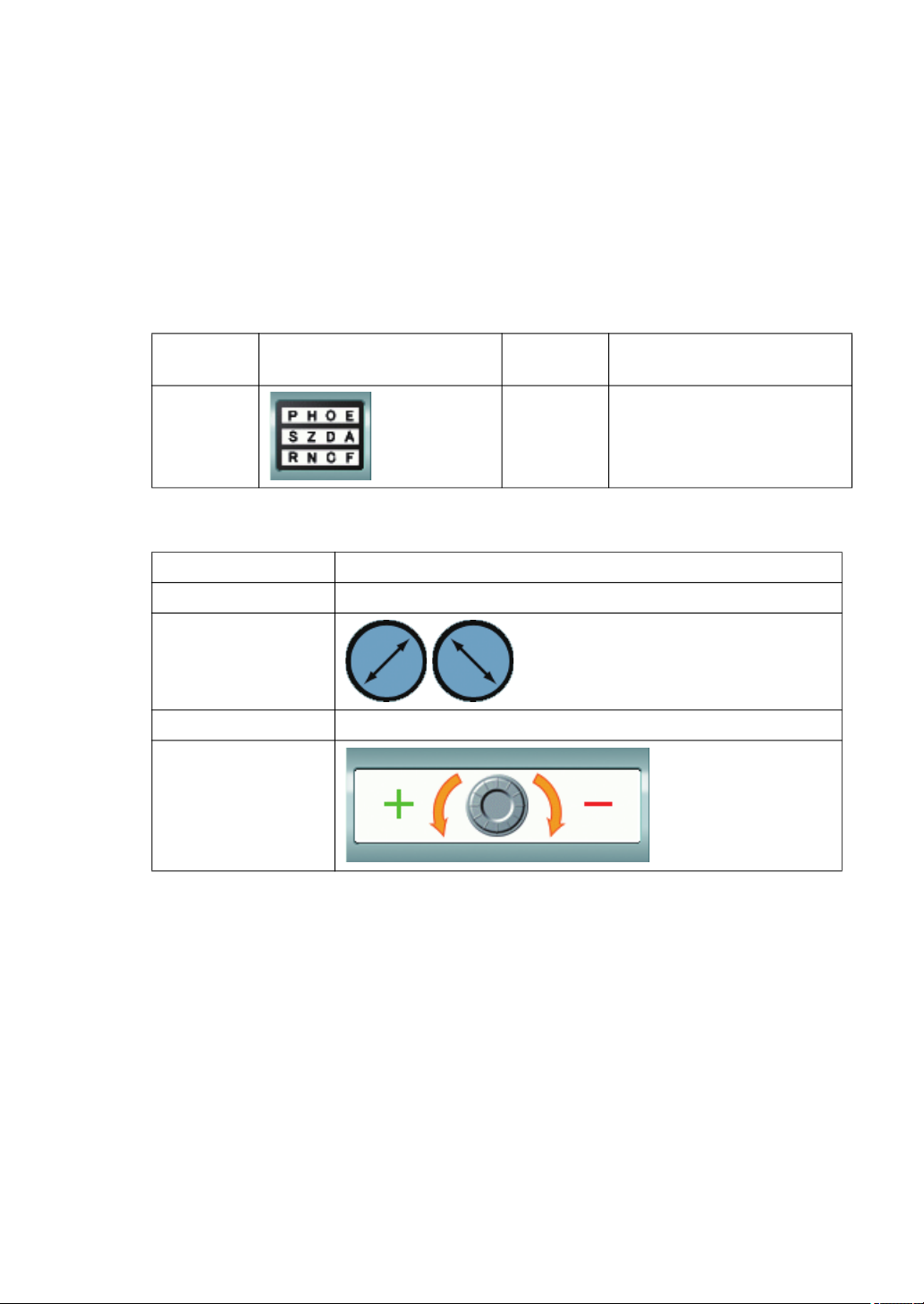
5.1.7 BALANCE TEST (POLARIZATION)
To make the patient's binocular vision clear, adjust the spherical power according to the visual
acuity balance of each eye.
1 Select the balance test (polarization) chart.
To perform the balance test (polarization), select the balance test (polarization) chart
icon on the chart page.
Example of the test chart icons on chart page
Far-point
chart
ACP-8(A) NC-3(E) -
The following items are automatically changed as shown below.
Item Description
Test eye Changed to the binocular mode.
Auxiliary lens
Dial operation mode The mode to operate the spherical power is selected.
Dial Navigation
Far-point test chart icon Near-point
chart
The polarized filter is set.
Near-point test chart icon
2 Adjust the balance.
Adjust the visual acuity balance between the right and left eyes.
The patient sees the upper row of letters with the right eye and the lower row of letters
with the left eye. Have the patient compare the top and bottom row of letters and answer
which row of letters is seen better, upper or lower.
When he/she sees better with the right eye, press the [R] switch on the controller unit.
When he/she sees better with the left eye, press the [L] switch. Then, turn the dial in the
"+" direction of "Dial Navigation" to add "+0.25D" to the spherical power.
In this state, have the patient compare the top and bottom row of letters again.
Finish the test in one of the following situations:
When the upper and lower row of letters are seen equally;
The test results just before the eye that sees better has been changed.
64
5. OPERATION FOR TESTS
Page 67
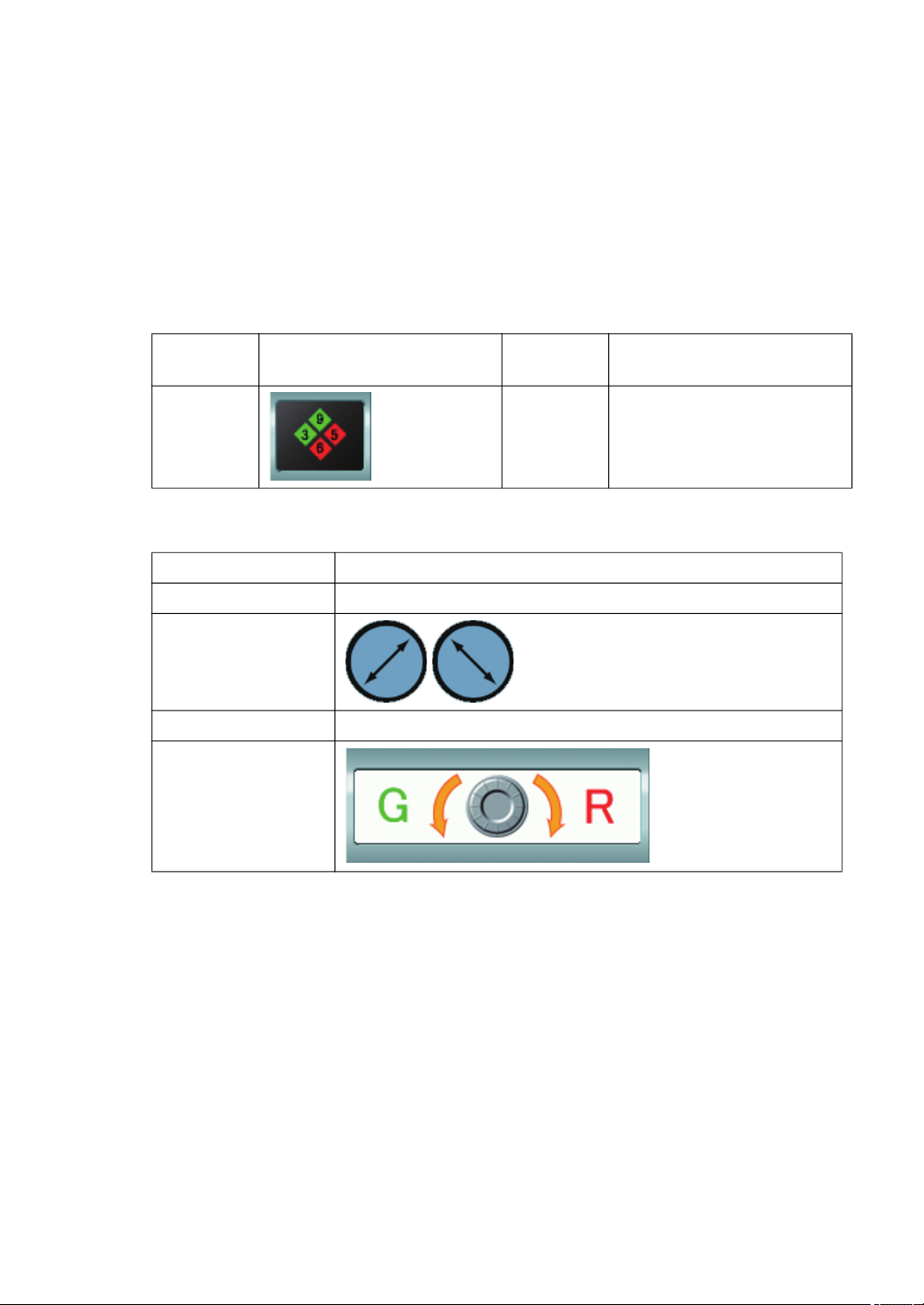
5.1.8 BALANCE TEST (POLARIZATION: 2-COLOR)
To make the patient's binocular vision clear, adjust the spherical power so that the refine end point
of each eye will be equal when the patient sees an object with both eyes.
1 Select the balance test (polarization: 2-color) chart.
To perform the balance test (polarization: 2-color), select the balance test (polarization:
2-color) chart on the chart page.
Example of the test chart icons on chart page
Far-point
chart
ACP-8(A) NC-3(E) -
The following settings are automatically changed as shown below.
Item Description
Test eye Changed to the binocular mode.
Auxiliary lens
Dial operation mode The mode to operate the spherical power is selected.
Dial Navigation
Far-point test chart icon Near-point
chart
The polarized filter is set.
Near-point test chart icon
2 Check the refined status of the right eye.
Adjust the refined status of the right eye on condition that the patient sees the chart binocularly. Press the [R] switch on the controller unit.
The patient sees the squares arranged in the vertical direction with the right eye and, the
ones in the horizontal direction with the left eye.
First, have the patient compare the characters of the red and green squares in the vertical direction and answer which square the character is seen better, on the red or green
side. When the character in the red square is seen better, turn the dial in the "R" direction of "Dial Navigation" by 1 step. When the character in the green square is seen better, turn the dial in the "G" direction by 1 step.
In this state, have the patient compare and answer again.
When the characters in the vertical direction are seen almost equally, the refinement of
the right eye is finished.
5. OPERATION FOR TESTS
65
Page 68
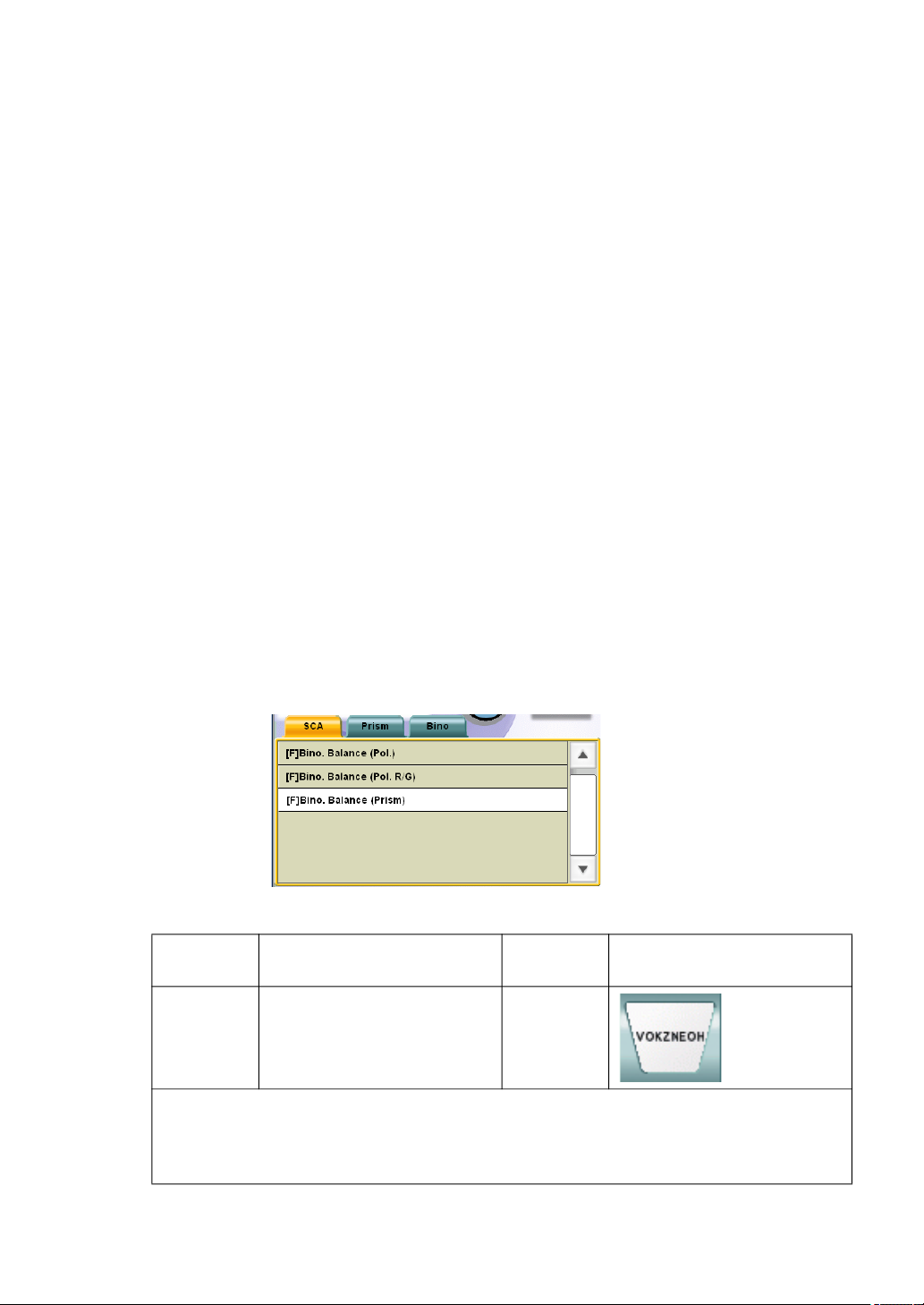
3 Check the adjusted status of the left eye.
Press the [L] switch on the controller unit.
Following the same procedure as the right eye, have the patient compare the characters
of the squares arranged in the horizontal direction to check the refined status of the left
eye.
When the characters in the horizontal position are seen almost equally, the adjustment
of the left eye is finished.
4 Check the adjusted status of both eyes.
Press the [B] switch on the controller unit.
Following the same procedure as mentioned prior, have the patient compare the characters of the red and green squares in the up-and-down and right-and-left directions to
check the adjusted status of both eyes.
When the characters in the green and red squares are seen almost equally through the
whole process, the test is finished.
5.1.9 BALANCE TEST (PRISM)
To make the patient's binocular vision clear, adjust the spherical power according to the visual
acuity balance of each eye. The only difference compared to the "Balance test (Polarization)" is
that a general visual acuity chart is used as the test chart.
1 Select "[F] Bino. Balance (Prism)" from "Exam list".
To execute this test, specify the test name from "Exam list".
Press the [Shift] and [Prog] switches on the controller unit at the same time to display
"Exam list".
Touch the [SCA] tab and select "[F] Bino. Balance (Prism)" from the displayed list.
To perform the near-point test, select the test chart icon shown below.
Far-point
chart
ACP-8(A) - NC-3(E)
In the far-point test, the chart where the characters are arranged on one horizontal line
or the visual acuity chart to which the horizontal mask is applied is set.
In near-point test, select the corresponding chart from the near-point card targets manually.
Far-point test chart icon Near-point
chart
Near-point test chart icon
66
5. OPERATION FOR TESTS
Page 69
The following settings are automatically changed as shown below.
Item Description
Test eye Changed to the binocular mode.
The base-up prism of "6 prism" is set
to the right eye.
Auxiliary lens
Dial operation mode
Dial Navigation
In far-point test, the mode to operate the spherical power is
selected.
In near-point test, the mode to operate ADD is selected.
(The left illustrations are the status as
seen from the user side as the CV5000 software screen.)
2 Adjust the balance.
Adjust the visual acuity balance between the right and left eyes.
The image the patient sees is separated top and bottom because of the prism inserted at
the right eye. The patient sees the upper section with the right eye and the lower section
with the left eye. Have the patient compare which section is seen better, upper or lower.
When he/she sees better with the right eye, press the [R] switch on the controller unit.
When he/she sees better with the left eye, press the [L] switch. Then, turn the dial in the
"+" direction of "Dial Navigation" to add "+0.25D" to the spherical power.
In this state, have the patient compare the upper and lower sections again.
Finish the test in one of the following situations:
When the upper and lower sections are seen equally;
The test results just before the eye that sees better has been changed.
67
5. OPERATION FOR TESTS
Page 70
5.2 PHORIA TEST
5.2.1 PHORIA TEST (POL. CROSS)
Measure heterophoria of the patient by using the "Pol. Cross" chart.
1 Select the "Phoria Test (Pol. Cross)" chart.
To perform "Phoria Test (Pol. Cross)", select the "Phoria Test (Pol. Cross)" chart icon on
the chart page.
Example of the test chart icons on chart page
Far-point
chart
ACP-8(A) NC-3(E) -
The following settings are automatically changed as shown below.
Item Description
Test eye
Auxiliary lens
Dial operation mode In initial status, the mode to operate "Horizontal prism" is set.
Far-point test chart icon Near-point
chart
Changed to the binocular mode.
When the dial operation mode is set to "Horizontal prism", the
left eye is the object of the dial operation.
When the dial operation mode is set to "Vertical prism", the
right eye is the object of the dial operation.
The polarized filter is selected.
Near-point test chart icon
Dial Navigation
68
5. OPERATION FOR TESTS
When the dial operation mode is set to
"Horizontal prism"
When the dial operation mode is set to
"Vertical prism"
Page 71

2 Check if the patient has heterophoria.
When the patient sees the test chart through the polarized filter, only the vertical lines
are seen with the right eye and only the horizontal lines, with the left eye.
If the patient does not have heterophoria, he/she sees the vertical line crossing the horizontal line at the center.
If the patient has horizontal phoria, the vertical and horizontal lines are disassociated in
the horizontal direction in his/her vision.
If the patient has vertical phoria, the vertical and horizontal lines are disassociated in the
vertical direction in his/her vision.
3 Measure the horizontal phoria value.
If the patient has horizontal phoria, measure its value.
If the dial operation mode is not set to "Horizontal prism", press the [H] switch on the
controller unit to change the mode.
Ask the patient which direction the vertical line is in relation to the horizontal line, right or
left.
When the vertical line is disassociated to the left, turn the dial to the left until the vertical
line reaches the center.
When the vertical line is disassociated to the right, turn the dial to the right until the horizontal line reaches the center.
4 Measure the vertical phoria value.
If the patient has vertical phoria, measure its value.
Press the [V] switch on the controller unit to change the dial operation mode to "Vertical
prism".
Ask the patient which direction the horizontal line is in relation to the vertical line, upward
or downward.
When the horizontal line is disassociated upward, turn the dial to the left until the horizontal line reaches the center.
When the horizontal line is disassociated downward, turn the dial to the right until the
horizontal line reaches the center.
69
5. OPERATION FOR TESTS
Page 72
5.2.2 PHORIA TEST (CROSS RING)
Measure heterophoria of the patient by using the "Cross Ring" chart.
1 Select the "Phoria Test (Cross Ring)" chart.
To perform a "Phoria Test (Cross Ring)", select the "Phoria Test (Cross Ring)" chart icon
on the chart page.
Example of the test chart icons on chart page
Far-point
chart
ACP-8(A) NC-3(E) -
The following settings are automatically changed as shown below.
Item Description
Test eye
Auxiliary lens
Dial operation mode In initial status, the mode to operate "Horizontal prism" is set.
Far-point test chart icon Near-point
chart
Changed to the binocular mode.
When the dial operation mode is set to "Horizontal prism", the
left eye is the object of the dial operation.
When the dial operation mode is set to "Vertical prism", the
right eye is the object of the dial operation.
The red lens is set to the right eye and
the green lens, to the left eye.
(The left illustrations are the status as
seen from the operator side as the
CV-5000 software screen.)
Near-point test chart icon
Dial Navigation
70
5. OPERATION FOR TESTS
When the dial operation mode is set to
"Horizontal prism"
When the dial operation mode is set to
"Vertical prism"
Page 73

2 Check if the patient has heterophoria.
When the patient sees the test chart through the red and green lenses, only the cross is
seen with the right eye and only the ring, with the left eye.
If the patient does not have heterophoria, the cross center overlaps the ring center in his/
her vision.
If the patient has horizontal phoria, the centers of cross and ring are disassociated in the
horizontal direction in his/her vision.
If the patient has vertical phoria, the centers of cross and ring are disassociated in the
vertical direction in his/her vision.
3 Measure the horizontal phoria value.
If the patient has horizontal phoria, measure its value.
If the dial operation mode is not set to "Horizontal prism", press the [H] switch on the
controller unit to change the mode.
Ask the patient which direction the cross is in relation to the ring, right or left.
When the cross is disassociated to the left against the ring, turn the dial to the left until
the vertical center lines of the cross and the ring overlap each other.
When the cross is disassociated to the right against the ring, turn the dial to the right until
the vertical center lines of the cross and the ring overlap each other.
4 Measure the vertical phoria value.
If the patient has vertical phoria, measure its degree.
Press the [V] switch on the controller unit to change the dial operation mode to "Vertical
prism".
Ask the patient which direction the cross is disassociated in relation to the ring, upward
or downward.
When the cross is disassociated downward in relation to the ring, turn the dial to the left
until the horizontal center lines overlap each other.
When the cross is disassociated upward in relation to the ring, turn the dial to the right
until the horizontal center lines overlap each other.
5.2.3 PHORIA TEST (MADDOX)
Measure heterophoria of the patient by using the fixation target and Maddox rod.
1 Prepare for the test.
The measurement of this test cannot be conducted correctly in a bright room. Perform
this test in a semi-dark room.
When you use the TOPCON visual acuity charts, ACP-8 and MC-3, the fixation target is
displayed. The fixation target may not provide the luminance required for the test as the
dot light source depending on the lighting of the test room. In this case, utilize a sufficient light source such as a penlight.
5. OPERATION FOR TESTS
71
Page 74
2 Select the "Phoria Test (Maddox)" chart.
To perform "Phoria Test (Maddox)", select the fixation target chart icon on the chart
page.
Example of the test chart icons on chart page
Far-point
chart
ACP-8(A) NC-3(E) -
The following settings are automatically changed as shown below.
Item Description
Test eye
Auxiliary lens
Far-point test chart icon Near-point
chart
Changed to the binocular mode.
When the dial operation mode is set to "Horizontal prism", the
left eye is the object of the dial operation.
When the dial operation mode is set to "Vertical prism", the
right eye is the object of the dial operation.
When the dial operation mode is set
to "Horizontal prism", the horizontal
Maddox rod lens is set to the right
eye.
When the dial operation mode is set
to "Vertical prism", the vertical Maddox rod lens is set to the left eye.
Near-point test chart icon
Dial operation mode In initial status, the mode to operate "Horizontal prism" is set.
Dial Navigation
72
5. OPERATION FOR TESTS
When the dial operation mode is set to
"Horizontal prism"
When the dial operation mode is set to
"Vertical prism"
Page 75

3 Check if the patient has heterophoria.
Press the [H] switch on the controller unit, and you can check if the patient has a horizontal phoria. Press the [V] switch, and you can check if the patient has vertical phoria.
When checking horizontal phoria, the horizontal Maddox rod lens is set to the right eye
and the dot light source is seen as a vertical line by the right eye.
If the patient does not have a horizontal phoria, the luminous point of the dot light source
that is seen by the left eye is on the vertical line that is seen by the right eye. If the
patient has horizontal phoria, the luminous point of the dot light source that is seen by
the left eye is separated from the line seen by the right eye.
When checking vertical phoria, the vertical Maddox rod lens is set to the left eye and the
dot light is seen as a horizontal line by the left eye.
If the patient does not have vertical phoria, the luminous point of the dot light source that
is seen by the right eye is on the horizontal line that is seen by the left eye. If the patient
has vertical phoria, the luminous point of the dot light source that is seen by the right eye
is separated from the line seen by the left eye.
4 Measure the horizontal phoria value.
If the patient has horizontal phoria, measure its value.
If the dial operation mode is not set to "Horizontal prism", press the [H] switch on the
controller unit to change the mode.
Ask the patient which side of the luminous point of the dot light exists, at the right or left
of the line.
When the dot light is at the right of the line, turn the dial to the left until the dot light and
line overlap each other.
When the dot light is at the left of the line, turn the dial to the right until the light source
and line overlap each other.
5 Measure the vertical phoria value.
If the patient has vertical phoria, measure its degree.
Press the [V] switch on the controller unit to change the dial operation mode to "Vertical
prism".
Ask the patient which side the luminous point of the dot light exists, above or under the
line.
When the dot light source is under the line, turn the dial to the left until the dot light and
line overlap each other.
When the dot light source is above the line, turn the dial to the right until the dot light and
line overlap each other.
73
5. OPERATION FOR TESTS
Page 76
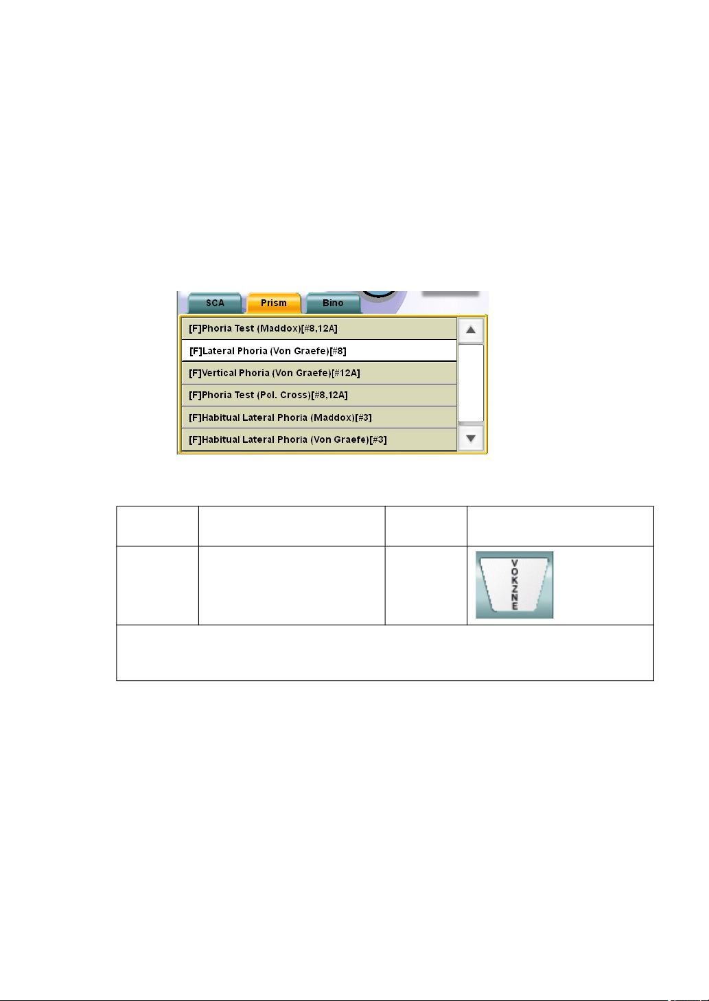
5.2.4 HORIZONTAL PHORIA MEASUREMENT (PRISM SEP-
ARATION)
Measure horizontal phoria of the patient by using the chart where characters are arranged on one
vertical line.
1 Select the chart where characters are positioned on one vertical line.
To perform the horizontal phoria measurement (prism separation), select the icon of the
chart where characters are positioned on one vertical line on the chart page.
If this icon does not exist on the chart page, press the [Shift] and [Prog] switches on the
controller unit at the same time to display "Exam list".
Touch the [Prism] tab and select "[F] Lateral Phoria (Von Graefe) [#8]" from "Exam list".
Example of the test chart icons on chart page
Far-point
chart
ACP-8(A) - NC-3(E)
In far-point test, the chart where the characters are arranged on one vertical line or the
visual acuity chart to which the vertical mask is applied is set.
In near-point test, set a proper target from the near-point card targets manually.
Far-point test chart icon Near-point
chart
Near-point test chart icon
74
5. OPERATION FOR TESTS
Page 77
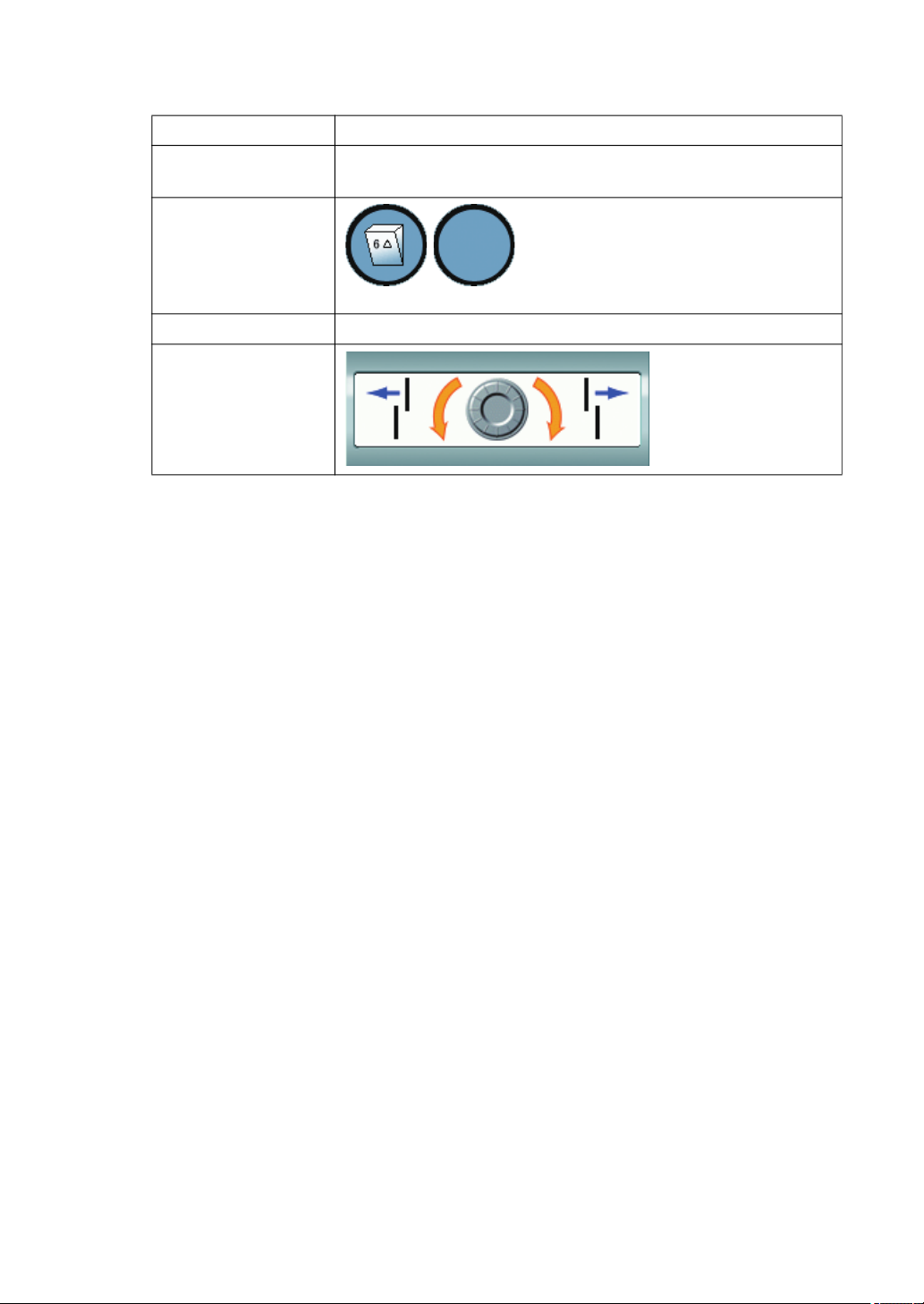
The following items are automatically changed as shown below.
Item Description
Test eye
Auxiliary lens
Dial operation mode The mode to operate "Horizontal prism" is set.
Dial Navigation
Changed to the binocular mode. The left eye is the object of
the dial operation.
The base-up prism of "6 prism" is set
to the right eye.
(The left illustrations are the status as
seen from the operator side as the
CV-5000 software screen.)
2 Check if the patient has heterophoria.
The image the patient sees is separated vertically because of the prism inserted over the
right eye. The patient sees the upper section with the right eye and the lower section
with the left eye.
If the patient does not have heterophoria, the characters on the upper and lower sections appear aligned.
If the patient has horizontal phoria, the characters of the upper and lower sections are
disassociated in the horizontal direction.
3 Measure the horizontal phoria value.
If the patient has horizontal phoria, measure its degree.
Ask the patient which direction the upper character line is disassociated against in relation to the lower character line, right or left.
When the upper character line is disassociated to the right, turn the dial to the left until
the upper and lower character lines appear aligned.
When the upper character line is disassociated to the left, turn the dial to the right until
the upper and lower character lines appear aligned.
75
5. OPERATION FOR TESTS
Page 78
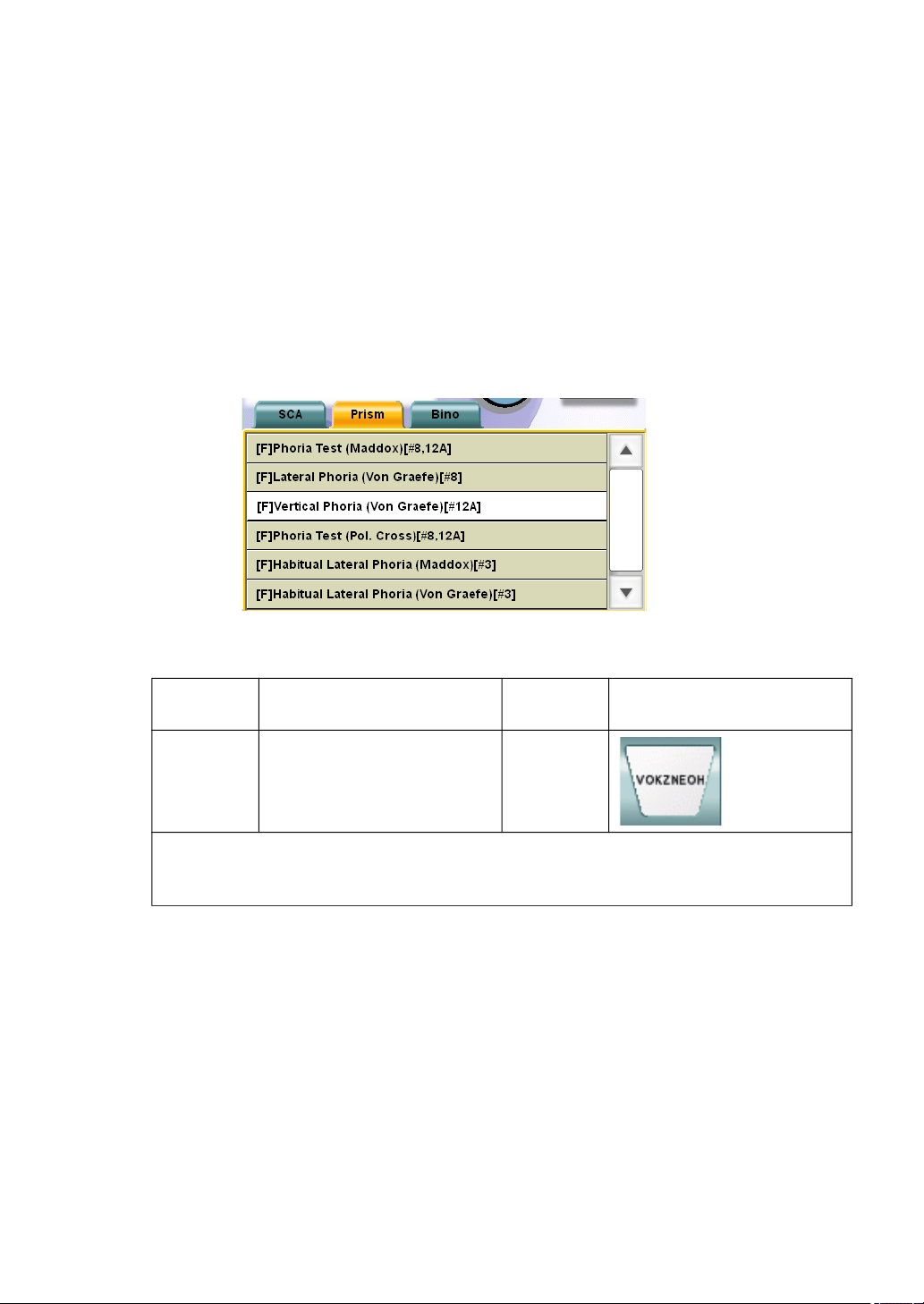
5.2.5 VERTICAL PHORIA MEASUREMENT (PRISM SEPARA-
TION)
Measure vertical phoria of the patient by using the chart where characters are arranged on one
horizontal line.
1 Select the chart where characters are arranged on one horizontal line.
To perform the vertical phoria measurement (prism separation), select the icon of the
chart where characters are arranged on one horizontal line on the chart page.
If this icon does not exist on the chart page, press the [Shift] and [Prog] switches on the
controller unit at the same time to display "Exam list".
Touch the [Prism] tab and select "[F] Vertical Phoria (Von Graefe) [#12A]" from "Exam
list".
Example of the test chart icons on chart page
Far-point
chart
ACP-8(A) - NC-3(E)
The chart where the characters are arranged on one horizontal line or the visual acuity
chart to which the horizontal mask is applied is set.
In near-point test, set a proper target from the near-point card targets manually.
Far-point test chart icon Near-point
chart
Near-point test chart icon
76
5. OPERATION FOR TESTS
Page 79
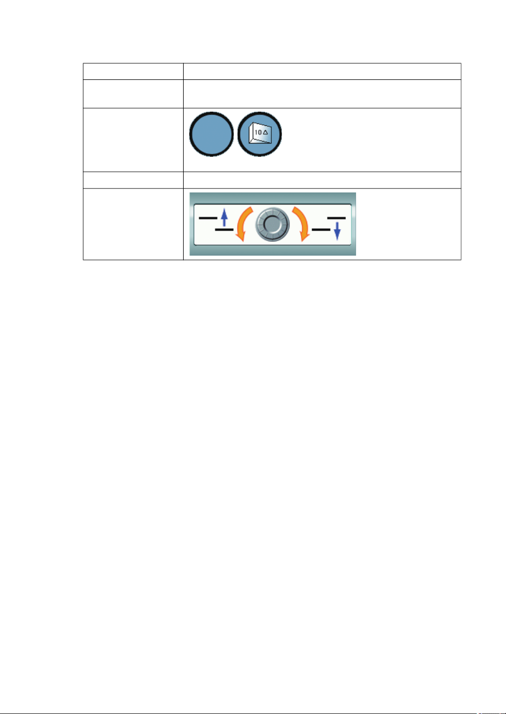
The following items are automatically selected as shown below.
Item Description
Test eye
Auxiliary lens
Dial operation mode The mode to operate "Vertical prism" is set.
Dial Navigation
Changed to the binocular mode. The right eye is the object of
the dial operation.
The base-in prism of "10 prism" is set
to the left eye.
(The left illustrations are the status as
seen from the operator side as the
CV-5000 software screen.)
2 Check if the patient has heterophoria.
The image the patient sees is separated horizontally because of the prism inserted over
the left eye. The patient sees the right section with the right eye and the left section with
the left eye.
If the patient does not have heterophoria, the characters on the horizontal sections
appear aligned.
If the patient has vertical phoria, the characters of the right and left sections are disassociated in the vertical direction.
3 Measure the vertical phoria value.
If the patient has vertical phoria, measure its value.
Ask the patient which direction the right character line is disassociated to in relation to
the left character line, upward or downward.
When the right character line is disassociated downward, turn the dial to the left until the
right and left character lines appear aligned.
When the right character line is disassociated upward, turn the dial to the right until the
right and left character lines appear aligned.
77
5. OPERATION FOR TESTS
Page 80
5.3 OTHER BINOCULAR FUNCTION TESTS
5.3.1 FIXATION DISPARITY TEST (POL. CROSS WITH FIXA-
TION TARGET)
Measure fixation disparity of the patient by using the cross chart with fixation target.
1 Prepare for the test.
This test must be executed without any disassociation of the eyes. Before this test, correct any disassociation of the eyes by conducting a "Phoria test".
For phoria test, refer to "5.2.1 PHORIA TEST (POL. CROSS)" on P.68.
2 Select the cross chart with fixation target.
To perform the fixation disparity test (cross with fixation target), select the icon for the
cross chart with fixation target on the chart page.
Example of the test chart icons on chart page
Far-point
chart
ACP-8(A) NC-3(E) -
Far-point test chart icon Near-point
chart
Near-point test chart icon
78
5. OPERATION FOR TESTS
Page 81
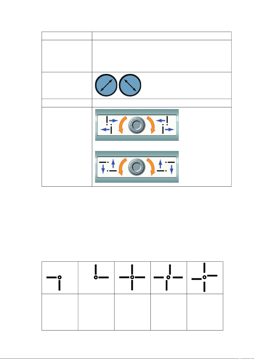
The following items are automatically selected as shown below.
Item Description
Changed to the binocular mode.
When the dial operation mode is set to "Horizontal prism", the
Test eye
Auxiliary lens
Dial operation mode In initial status, the mode to operate "Horizontal prism" is set.
Dial Navigation
left eye is the object of the dial operation.
When the dial operation mode is set to "Vertical prism", the
right eye is the object of the dial operation.
The polarized filter is set.
When the dial operation mode is set to
"Horizontal prism"
When the dial operation mode is set to
"Vertical prism"
3 Check if the patient has fixation disparity.
When the patient sees the test chart through the polarized filter, the following status is
his/her vision: The fixation target at the cross center is seen by both eyes. In addition,
the reversed "L" shape made by the vertical and horizontal lines is seen by the left eye.
The "L" shape is seen by the right eye.
If the patient does not have fixation disparity, he/she sees a cross made by the straight
vertical and horizontal lines.
If the patient has fixation disparity in the horizontal direction, the vertical lines are deviated in the horizontal direction in his/her vision.
If the patient has fixation disparity in the vertical direction, the horizontal lines are deviated in the vertical direction in his/her vision.
Chart seen by
left eye
Chart seen by
right eye
Chart seen by
both eyes
without fixation disparity
Example for
the eye having fixation
disparity in
horizontal
direction
Example for
the eye having fixation
disparity in
vertical direction
79
5. OPERATION FOR TESTS
Page 82
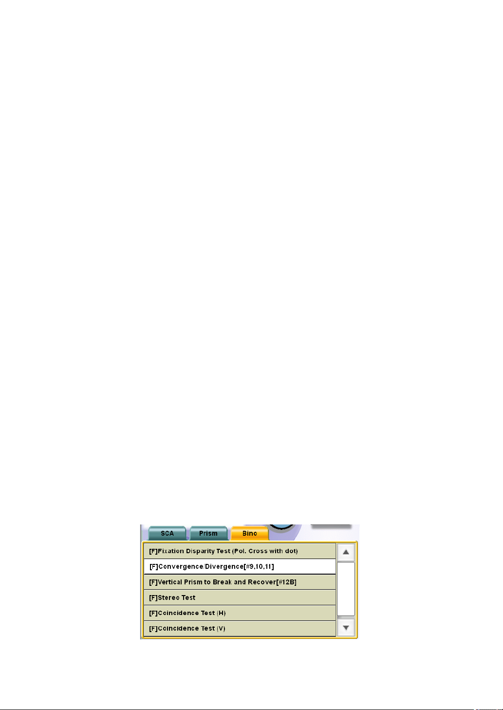
4 Measure the fixation disparity degree in the horizontal direction.
If the patient has fixation disparity in the horizontal direction, measure its value.
If the dial operation mode is not set to "Horizontal prism", press the [H] switch on the
controller unit to change the mode.
Have the patient view the vertical lines. Ask the patient which direction the upper vertical
line is compared to the lower vertical line, right or left.
When the upper vertical line is at the left against the lower vertical line, turn the dial to
the left until the upper and lower vertical lines appear aligned.
When the upper vertical line is at the right against the lower vertical line, turn the dial to
the right until the upper and lower vertical lines appear aligned.
5 Measure the fixation disparity value in the vertical direction.
If the patient has fixation disparity in the vertical direction, measure its value.
If the dial operation mode is not set to "Vertical prism", press the [V] switch on the controller unit to change the mode.
Have the patient view the horizontal lines. Ask the patient which direction the right horizontal line appears, under or above the left horizontal line.
When the right horizontal line is under the left horizontal line, turn the dial to the left until
the right and left horizontal lines appear aligned.
When the right horizontal line is above the left horizontal line, turn the dial to the right
until the right and left horizontal lines appear aligned.
5.3.2 CONVERGENCE/DIVERGENCE
Measure the convergence and divergence of the patient. The result is used as a reference value
when the heterophoria of the patient is corrected.
The result of the test is recorded by touching the function buttons.
1 Prepare for the test.
This test must be executed in the condition that abnormal refraction has been completely corrected. If abnormal refraction is not corrected yet, correct it before this test.
2 Select "Convergence/Divergence" from "Exam list".
To perform this test, specify the test name from "Exam list".
Press the [Shift] and [Prog] switches on the controller unit at the same time to display
"Exam list".
Touch the [Bino] tab and select "[F] Convergence/Divergence[#9, 10, 11]" from the list.
80
5. OPERATION FOR TESTS
Page 83
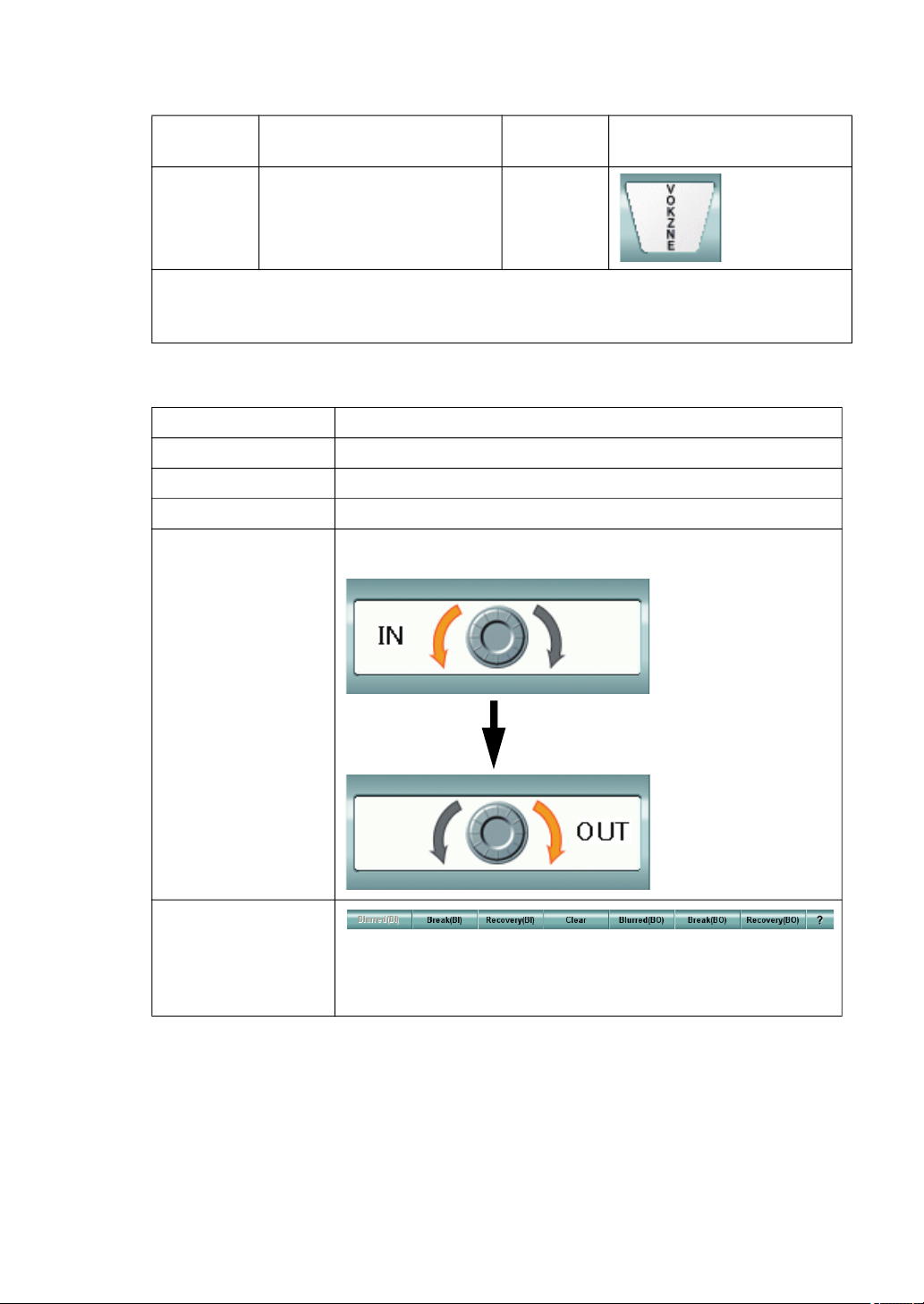
To perform the near-point test, select the test chart icon shown below.
Far-point
chart
ACP-8(A) - NC-3(E)
In far-point test, the chart where the characters are arranged on one vertical line or the
visual acuity chart to which the vertical mask is applied is set.
In near-point test, set a proper target from the near-point card targets manually.
The following items are automatically changed as shown below.
Item Description
Test eye Changed to the binocular mode.
Auxiliary lens Not set.
Dial operation mode The mode to operate "Horizontal prism" is set.
Far-point test chart icon Near-point
chart
According to the progress of the test, the following two types
are alternately displayed.
Near-point test chart icon
Dial Navigation
Function button In far-point test, blur is not generated in the case of diver-
gence. So, the [Blurred (BI)] button at the leftmost of the
function buttons is displayed in the invalid status.
81
5. OPERATION FOR TESTS
Page 84

3 Measure divergence.
First, measure the divergence of the patient.
Have the patient view the chart where characters are arranged on one vertical line.
[Checking the blur point] (Only for near point)
Instruct the patient to respond whenever he/she sees the blurred characters on the
chart. Then, turn the dial slowly in the direction indicated by "Dial Navigation".
When the patient says "I see the blurred characters", stop turning the dial. Check if the
patient still sees the blurred characters though the user tries to adjust the focus correctly.
When the patient says positively "I see the blurred characters", touch the [Blurred (BI)]
button to record the measured value.
[Checking the break point]
Instruct the patient to respond whenever he/she sees the characters on two lines, which
are, in fact, arranged vertically on one line in the chart. Then, turn the dial slowly in the
direction indicated by "Dial Navigation".
When the patient says "I see the characters on two lines", touch the [Break (BI)] button
to record the measured value.
[Checking the recovery point]
Instruct the patient to respond whenever he/she sees the characters on one line again.
Then, turn the dial in the direction indicated by "Dial Navigation".
When the patient says "I see the characters on one line", touch the [Recovery (BI)] button to record the measured value.
4 Measure convergence.
Measure the convergence of the patient.
Before proceeding to the convergence measurement, touch the [Clear] button to cancel
the prism set currently.
[Checking the blur point]
Instruct the patient to respond whenever he/she sees the blurred characters on the
chart. Then, turn the dial slowly in the direction indicated by "Dial Navigation".
When the patient says "I see the blurred characters", stop turning the dial. Check if the
patient still sees the blurred characters while the operator tries to adjust the focus correctly. When the patient says positively "I see the blurred characters", touch the [Blurred
(BO)] button to record the measured value.
[Checking the break point]
Instruct the patient to respond whenever he/she sees the characters on two lines, which
are, in fact, arranged on one line horizontally in the chart. Then, turn the dial slowly in
the direction indicated by "Dial Navigation".
When the patient says "I see the characters on two lines", touch the [Break (BO)] button
to record the measured value.
[Checking the recovery point]
Instruct the patient to respond whenever he/she sees the characters on one line again.
Then, turn the dial in the direction indicated by "Dial Navigation".
When the patient says "I see the characters on one line", touch the [Recovery (BO)] button to record the measured value.
82
5. OPERATION FOR TESTS
Page 85
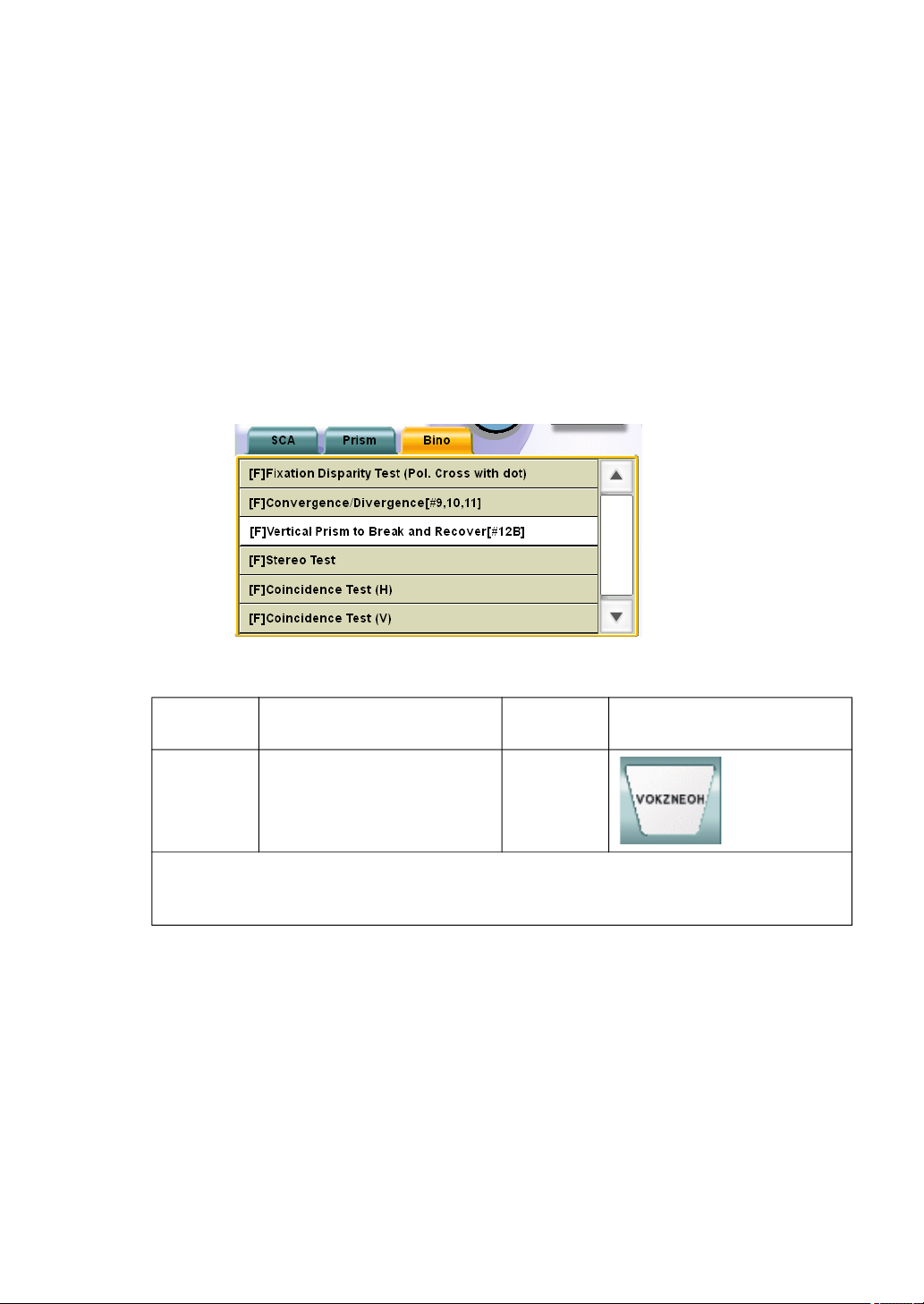
5.3.3 Vertical vergence
Measure the vertical vergence of the patient. The result of the test is recorded by touching the
function buttons.
1 Prepare for the test.
This test must be executed in the condition that refractive error has been completely corrected. If refractive error is not corrected yet, correct it before this test.
2 Select "[F] Vertical Prism to Break and Recover [#12B]" from "Exam list".
To perform this test, specify the test name from the "Exam list".
Press the [Shift] and [Prog] switches on the controller unit at the same time to display
"Exam list".
Touch the [Bino] tab and then select "[F] Vertical Prism to Break and Recover [#12B]"
from the list.
To perform the near-point test, select the test chart icon shown below.
Far-point
chart
ACP-8(A) - NC-3(E)
In far-point test, the chart where the characters are arranged on one horizontal line or
the visual acuity chart to which the horizontal mask is applied is set.
In near-point test, set a proper target from the near-point card targets manually.
Far-point test chart icon Near-point
chart
Near-point test chart icon
83
5. OPERATION FOR TESTS
Page 86
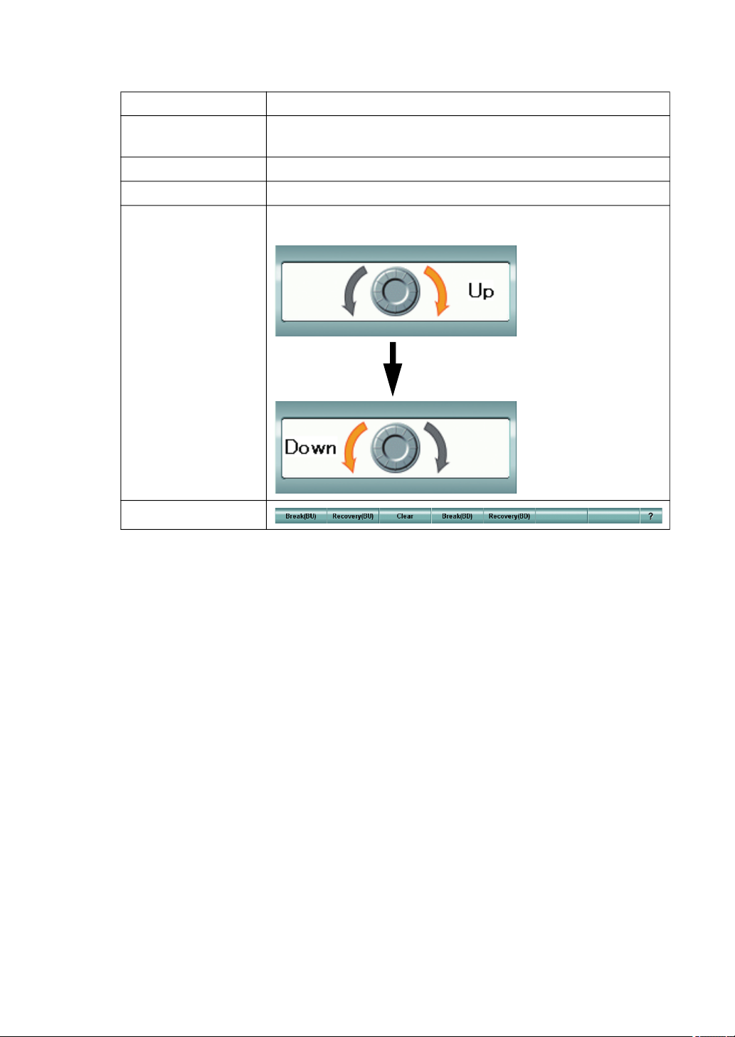
The following items are automatically selected as shown below.
Item Description
Test eye
Auxiliary lens Not set.
Dial operation mode The mode to operate "Vertical prism" is set.
Dial Navigation
Changed to the binocular mode. The right eye is the object of
the dial operation.
According to the progress of the test, the following two types
are alternately displayed.
Function button
3 Measure the upper divergence of the left eye.
First, measure the upper divergence of the left eye for the patient.
Have the patient view the chart where characters are arranged on one horizontal line.
[Checking the break point]
Instruct the patient to respond whenever he/she sees the characters on two lines, which
are, in fact, arranged horizontally on one line in the chart. Then, turn the dial slowly in
the direction indicated by "Dial Navigation".
When the patient says "I see the characters on two lines", touch the [Break (BU)] button
to record the measured value.
[Checking the recovery point]
Instruct the patient to respond whenever he/she sees the characters on one line again.
Then, turn the dial in the direction indicated by "Dial Navigation".
When the patient says "I see the characters on one line", touch the [Recovery (BU)] button to record the measured value.
84
5. OPERATION FOR TESTS
Page 87
4 Measure the upper divergence of the right eye.
Measure the upper divergence of the right eye for the patient.
Before proceeding to the upper divergence measurement of the right eye, touch the
[Clear] button to cancel the prism set currently.
[Checking the break point]
Instruct the patient to respond whenever he/she sees the characters on two lines, which
are, in fact, arranged horizontally on one line in the chart. Then, turn the dial slowly in
the direction indicated by "Dial Navigation".
When the patient says "I see the characters on two lines", touch the [Break (BD)] button
to record the measured value.
[Checking the recovery point]
Instruct the patient to respond whenever he/she sees the characters on one line again.
Then, turn the dial in the direction indicated by "Dial Navigation".
When the patient says "I see the characters on one line", touch the [Recovery (BD)] button to record the measured value.
5.3.4 STEREO TEST
Check if the patient has the stereoscopic vision.
1 Select the stereoscopic vision test chart.
To perform the stereoscopic vision test, select the icon for the stereoscopic vision test on
the chart page.
Example of the test chart icons on chart page
Far-point
chart
ACP-8(A) NC-3(E) -
Far-point test chart icon Near-point
chart
Near-point test chart icon
85
5. OPERATION FOR TESTS
Page 88
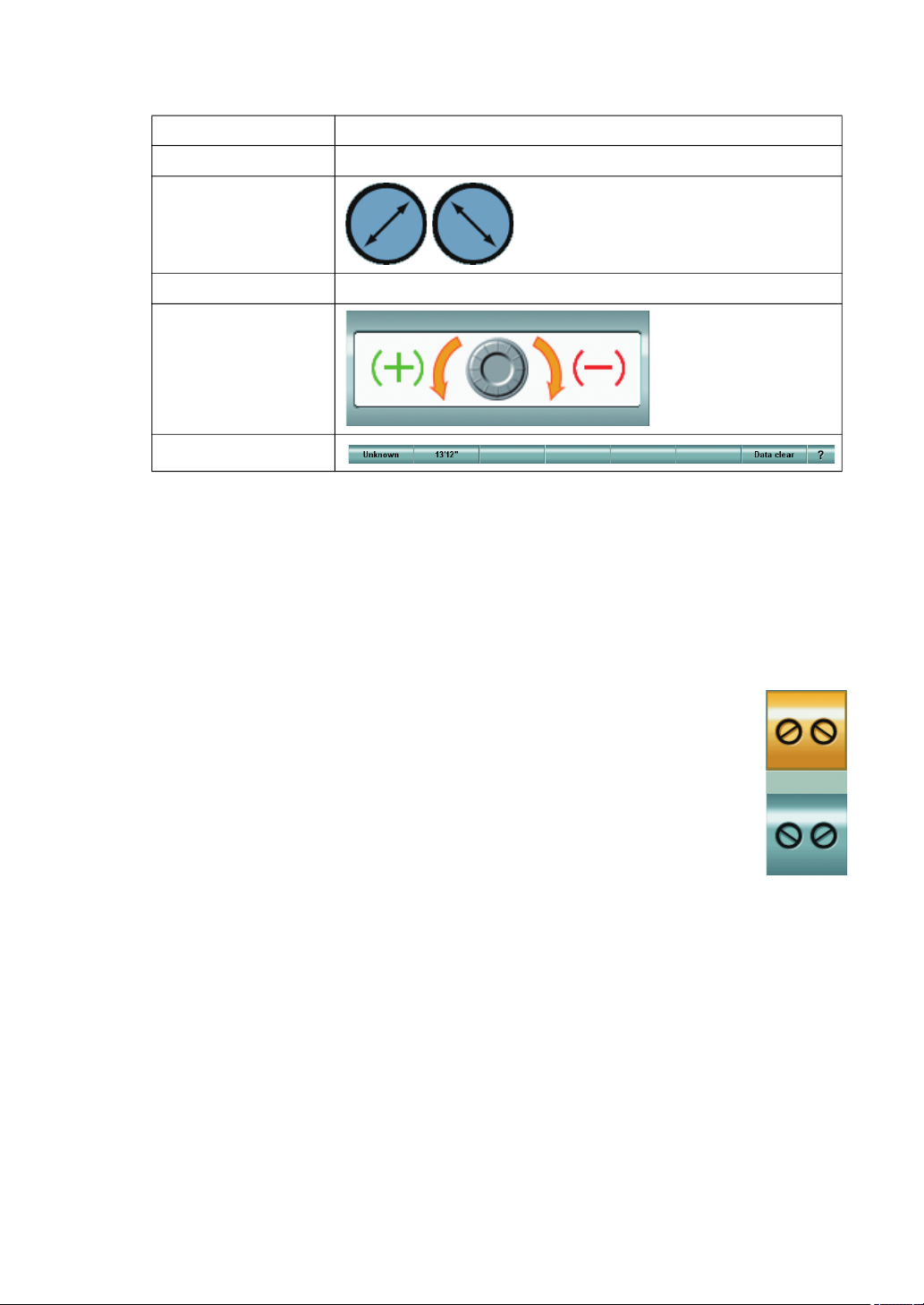
The following items are automatically changed as shown below.
Item Description
Test eye Changed to the binocular mode.
The polarized filter is set.
Auxiliary lens
Dial operation mode The last status is succeeded.
Dial Navigation
Function button
2 Check the stereoscopic vision.
When the patient sees the test chart through the polarized filter, the center point and
upper and lower lines are seen on two different planes.
If the patient recognizes the different planes, he/she can see a solid body of parallax
13’12".
To record the test result, touch the [13’12"] button.
When the patient cannot recognize the relief and sunk status, touch the [Unknown] button.
3 Reverse the polarized filter angle and check the stereoscopic vision again.
When the dial operation mode is set anything except "Prism", the polarization auxiliary lens reverse button is displayed as a side button. Touch this
button. The polarized filter is reversed and the orientation of the two planes
are reversed.
If the patient recognizes the two different planes, he/she can see a solid
body of parallax 13’12".
To record the test result, touch the [13’12"] button.
When the patient cannot recognize the two different planes, touch the
[Unknown] button.
86
5. OPERATION FOR TESTS
Page 89
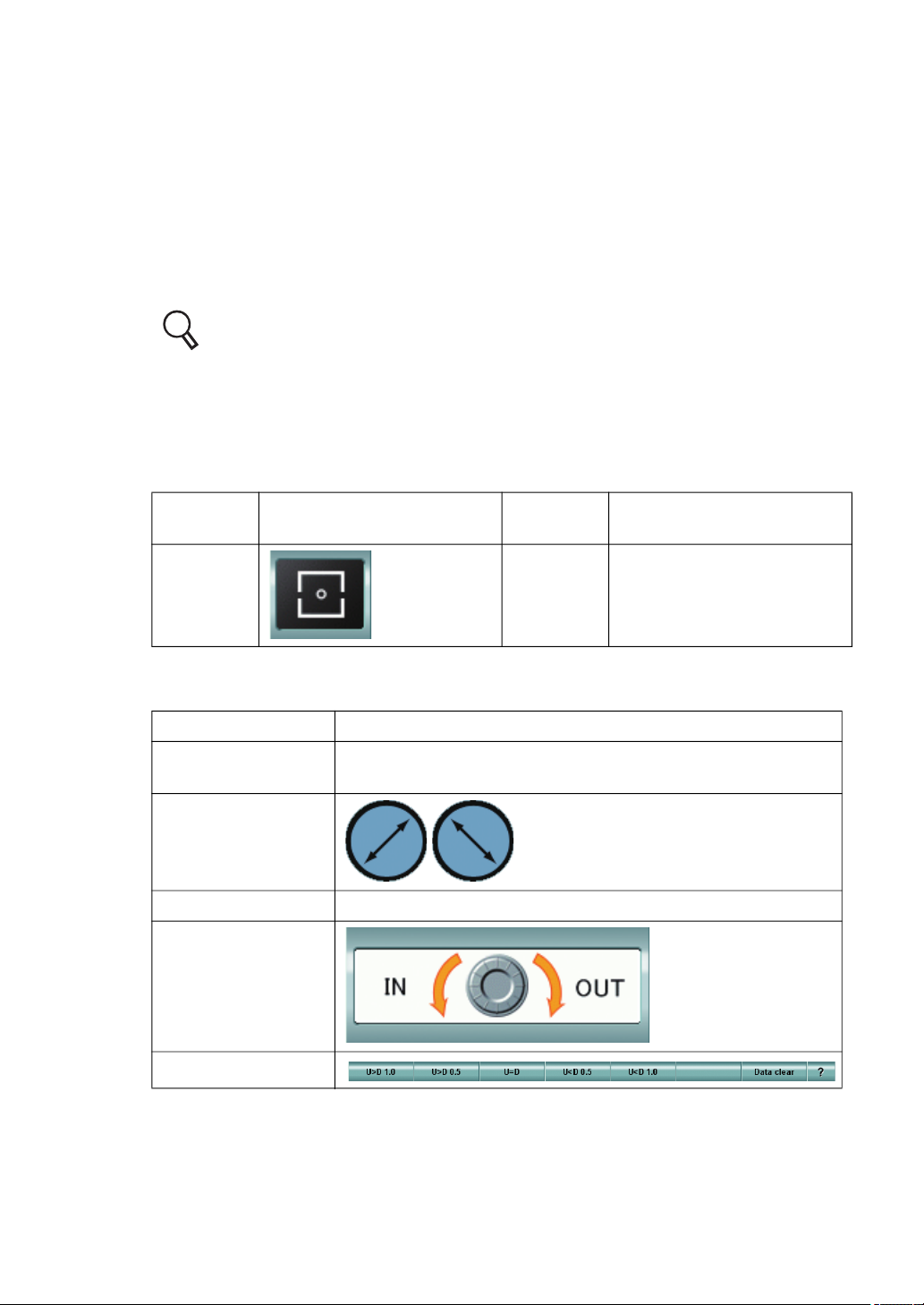
5.3.5 COINCIDENCE TEST (H) (Only for ACP-8)
When the patient sees the image in the horizontal direction after correction, the image size seen
by the right eye may be different from the image seen by the left eye. In this test, check if the
image size is different between the right and left eyes.
If there is a difference of one line (7%) or more, it is recommended to recheck the correction value.
1 Prepare for the test.
If heterophoria is not corrected, the patient's eye may not be refined properly. Before
this test, correct heterophoria.
For phoria test, refer to "5.2.1 PHORIA TEST (POL. CROSS)" on P.68.
2 Select the horizontal aniseikonia test chart.
To perform the horizontal aniseikonia test, select the icon for the horizontal aniseikonia
test on the chart page.
Example of the test chart icons on chart page
Far-point
chart
ACP-8(A) NC-3(E) -
The following items are automatically changed as shown below.
Item Description
Test eye
Auxiliary lens
Dial operation mode The mode to operate "Horizontal prism" is set.
Dial Navigation
Far-point test chart icon Near-point
chart
Changed to the binocular mode. The left eye is the object of
the dial operation.
The polarized filter is set.
Near-point test chart icon
Function button
87
5. OPERATION FOR TESTS
Page 90
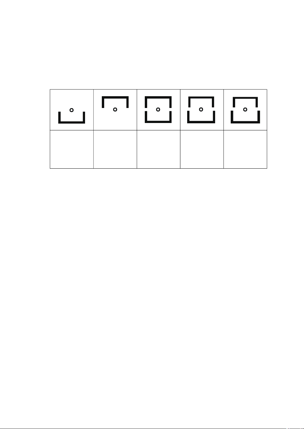
3 Check the horizontal aniseikonia.
When the patient sees the test chart through the polarized filter, the center fixation target
is seen by both eyes as shown below. In addition, the upper half is seen by the right eye
and the lower half, by the left eye.
When the patient does not have horizontal aniseikonia, he/she sees the upper and lower
images in the same size.
When the patient has horizontal aniseikonia, he/she sees the upper and lower images in
different sizes.
Chart seen by
left eye
Chart seen by
right eye
Chart seen by
the eyes without horizontal
aniseikonia
Disparity by
half a line
(Example of
"U<D")
Disparity by
one line
(Example of
"U<D")
4 Record the horizontal aniseikonia degree.
Have the patient answer whether the upper and lower images are different in size. If
yes, have the patient view the opening of the upper and lower images and answer how
much the lines are different in relation to each other.
When the disparity at one side is about half a line, the patient should answer "half a line".
When it is about one line, the patient should answer "one line".
When the upper image is larger than the lower one by one line, touch the [U>D 1.0] button to record the value.
When the upper image is larger than the lower one by half a line, touch the [U>D 0.5]
button to record the value.
When the lower image is larger than the upper one by one line, touch the [U<D 1.0] button to record the value.
When the lower image is larger than the upper one by half a line, touch the [U<D 0.5]
button to record the value.
When the upper and lower images are the same size, touch the [U=D] button to record
the value.
When disparity of half a line is recognized, the magnification is different by 3.5%
between the images of the right and left eyes. When disparity of one line is recognized,
it is different by 7.0%.
88
5. OPERATION FOR TESTS
Page 91
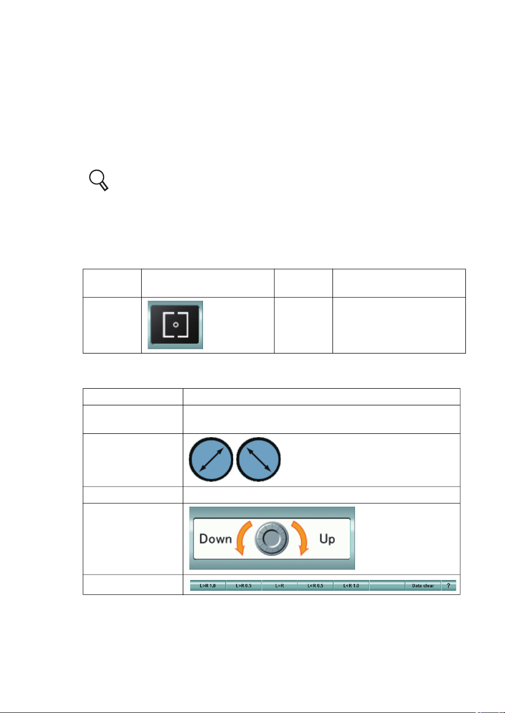
5.3.6 COINCIDENCE TEST (V)
When the patient sees the image in the vertical direction after correction, the image size seen by
the right eye may be different from the image seen by the left eye. In this test, check if the image
size is different between the right and left eyes.
If there is a difference of one line (7%) or more, it is recommended to recheck the correction value.
1 Prepare for the test.
If heterophoria is not corrected, the patient's eye may not be refined properly. Before
this test, correct heterophoria.
For phoria test, refer to "5.2.1 PHORIA TEST (POL. CROSS)" on P.68.
2 Select the vertical aniseikonia test chart.
To perform the vertical aniseikonia test, select the icon for the vertical aniseikonia test on
the chart page.
Example of the test chart icons on chart page
Far-point
chart
ACP-8(A) NC-3(E) -
The following items are automatically changed as shown below.
Item Description
Test eye
Auxiliary lens
Dial operation mode The mode to operate "Vertical prism" is set.
Dial Navigation
Far-point test chart icon Near-point
chart
Changed to the binocular mode. The right eye is the object of
the dial operation.
The polarized filter is set.
Near-point test chart icon
Function button
89
5. OPERATION FOR TESTS
Page 92
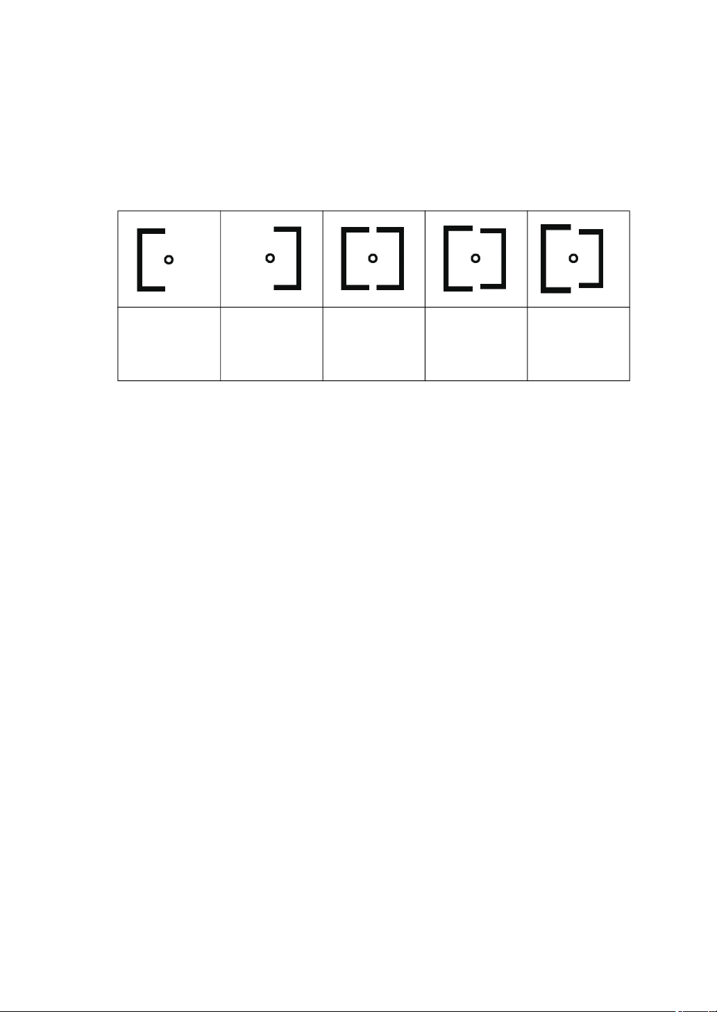
3 Check the vertical aniseikonia.
When the patient sees the test chart through the polarized filter, the center fixation target
is seen by both eyes as shown below. In addition, the left half is seen by the left eye and
the right half, by the right eye.
When the patient does not have vertical aniseikonia, he/she sees the right and left
images appear same size.
When the patient has vertical aniseikonia, he/she sees the right and left images in different sizes.
Chart seen by
left eye
Chart seen by
right eye
Chart seen by
the eyes without vertical
aniseikonia
Disparity by
half a line
(Example of
"L>R")
Disparity by
one line
(Example of
"L>R")
4 Record the vertical aniseikonia degree.
Have the patient answer whether the right and left images are different in size. If so,
have the patient view the opening of the right and left images and answer how much the
lines are disparate to each other.
When the disparity at one side is about half a line, the patient should answer "half a line".
When it is about one line, the patient should answer "one line".
When the left image is larger than the right one by one line, touch the [L>R 1.0] button to
record the value.
When the left image is larger than the right one by half a line, touch the [L>R 0.5] button
to record the value.
When the right image is larger than the left one by one line, touch the [L<R 1.0] button to
record the value.
When the right image is larger than the left one by half a line, touch the [L<R 0.5] button
to record the value.
When the right and left images have same size, touch the [L=R] button to record the
value.
When disparity of half a line is checked, the magnification is different by 3.5% between
the images of right and left eyes. When disparity of one line is checked, it is different by
7.0%.
90
5. OPERATION FOR TESTS
Page 93
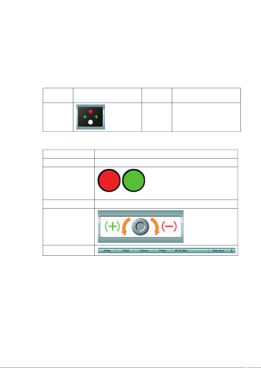
5.3.7 WORTH 4 DOTS TEST
Check if the patient has strabismus and suppression.
1 Select the Worth 4 dots test chart.
To perform the Worth 4 dots test, select the icon for the Worth 4 dots test on the chart
page.
Example of the test chart icons on chart page
Far-point
chart
ACP-8(A) NC-3(E) -
The following items are automatically changed as shown below.
Item Description
Test eye Changed to the binocular mode.
Auxiliary lens
Dial operation mode The last status is succeeded.
Dial Navigation
Far-point test chart icon Near-point
chart
The red lens is set to the right eye and
the green lens, to the left eye.
(The left illustrations are the status as
seen from the operator side as the
CV-5000 software screen.)
Near-point test chart icon
Function button
91
5. OPERATION FOR TESTS
Page 94
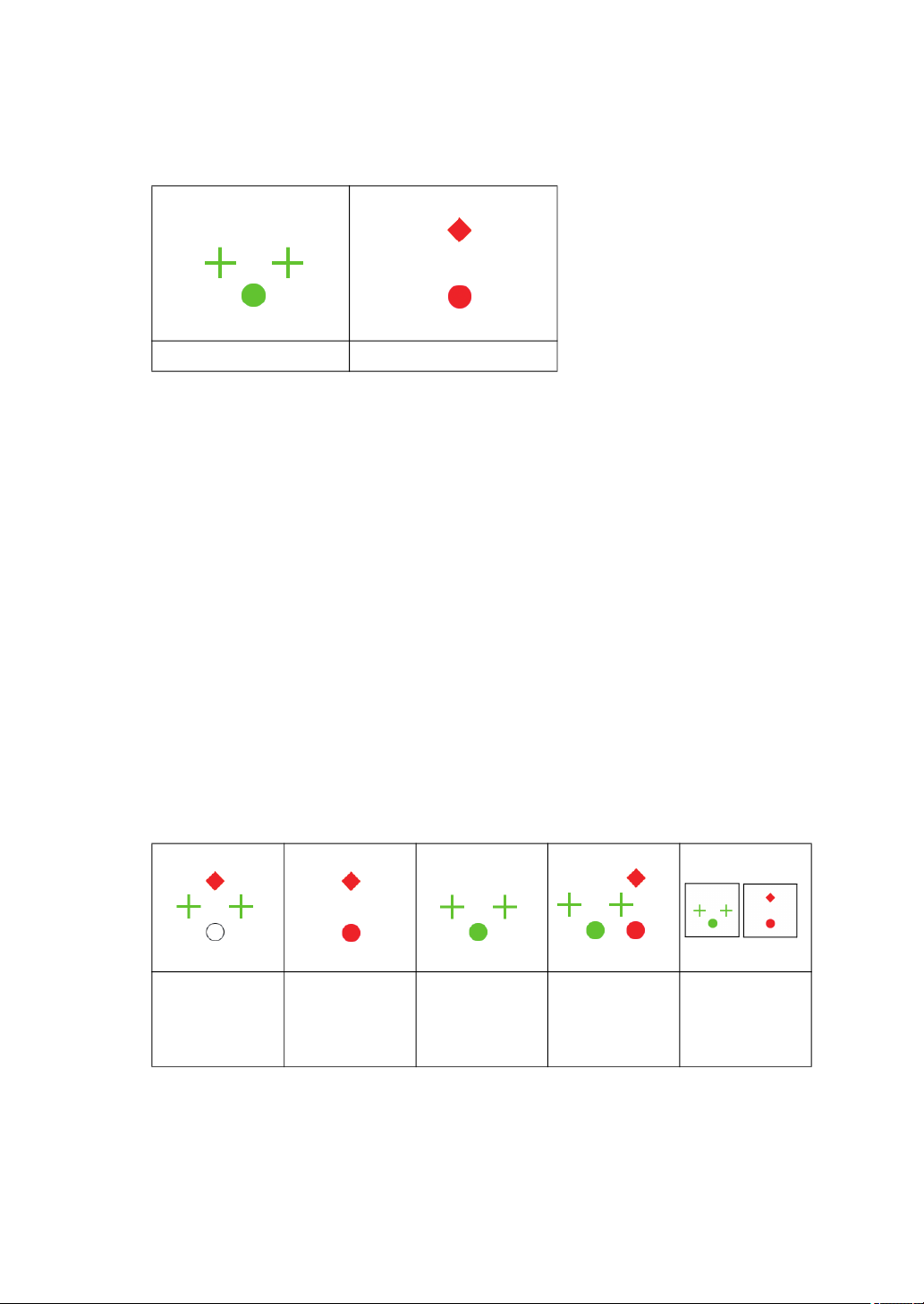
2 Check how the chart is seen.
When the patient sees the test chart by each eye through the red and green auxiliary
lenses, the three green shapes are seen by the left eye and the two red shapes are seen
by the right eye.
Chart seen by left eye Chart seen by right eye
When the patient sees the chart with both eyes at the same time, there are five types of
the conditions as described below.
[4 Dots]
When the patient sees the four shapes, he/she does not have strabismus or he/she has
abnormal concordance.
The lowest white shape is seen in red, green or a mix of red and green. When the lowest shape is seen in red, the right eye is superior. When it is seen in green, the left eye
is superior. When it is seen in the mixed color, the right and left eyes are balanced.
[2 Red]
When the patient sees the two red shapes, the left eye is suppressed if he/she sees an
object with both eyes.
[3 Green]
When the patient sees the three green shapes, the right eye is suppressed if he/she
sees an object with both eyes.
[5 Dots]
When the patient sees the two red shapes and three green shapes, the patient has strabismus.
[2R 3G Alter]
When the patient sees the red and green shapes alternately, he/she has alternating suppression.
4 Shapes
(Normal/
Abnormal
concordance)
3 Record the result.
Ask the patient how he/she sees the chart and touch the function button meeting his/her
answer to record the result.
92
5. OPERATION FOR TESTS
2 Red (Suppression on
left eye)
3 Green
(Suppression
on right eye)
5 Shapes
(Strabismus)
2R 3G alter
(Alternating
suppression)
Page 95
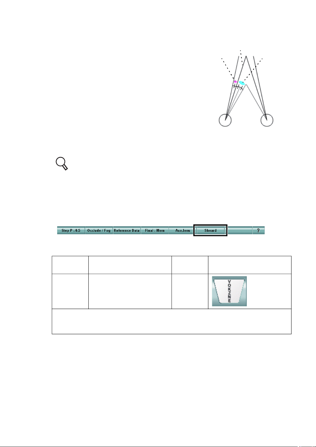
5.3.8 SHEARD'S CRITERIA
Sheard's criteria is a theory that, to keep normal binocular function, the extra convergence or divergence that is twice as large
as heterophoria or more is necessary.
In this test, check if the patient has extra convergence or divergence that meets Sheard's criteria according to the measured
heterophoria.
If there is extra convergence or divergence that meets Sheard's
criteria, it is judged that prism prescription is not necessary.
If this isn’t the case, the program calculates the prism quantity
that makes up for the insufficiency automatically.
1 Prepare for the test.
This test must be executed after the horizontal phoria has already been measured.
Before this test, measure horizontal phoria.
For the horizontal phoria test, refer to "5.2.4 HORIZONTAL PHORIA MEASUREMENT (PRISM SEPARATION)" on P.74.
2 Touch the [Sheard] button.
While the phoria test is being executed, the [Sheard] button is displayed as a function
button.
This [sheard] button is valid when horizontal phoria is measured. After the horizontal
phoria has been measured, touch this button.
Heterophoria
Eye line
Extra convergence
To perform the near-point test, select the test chart icon shown below.
Far-point
chart
ACP-8(A)
In far-point test, the chart where the characters are arranged on one vertical line or the
visual acuity chart to which the vertical mask is applied is set.
In near-point test, set a proper target from the near-point card targets manually.
Far-point test chart icon Near-point
chart
This test is conducted at
near only.
NC-3(E)
Near-point test chart icon
93
5. OPERATION FOR TESTS
Page 96
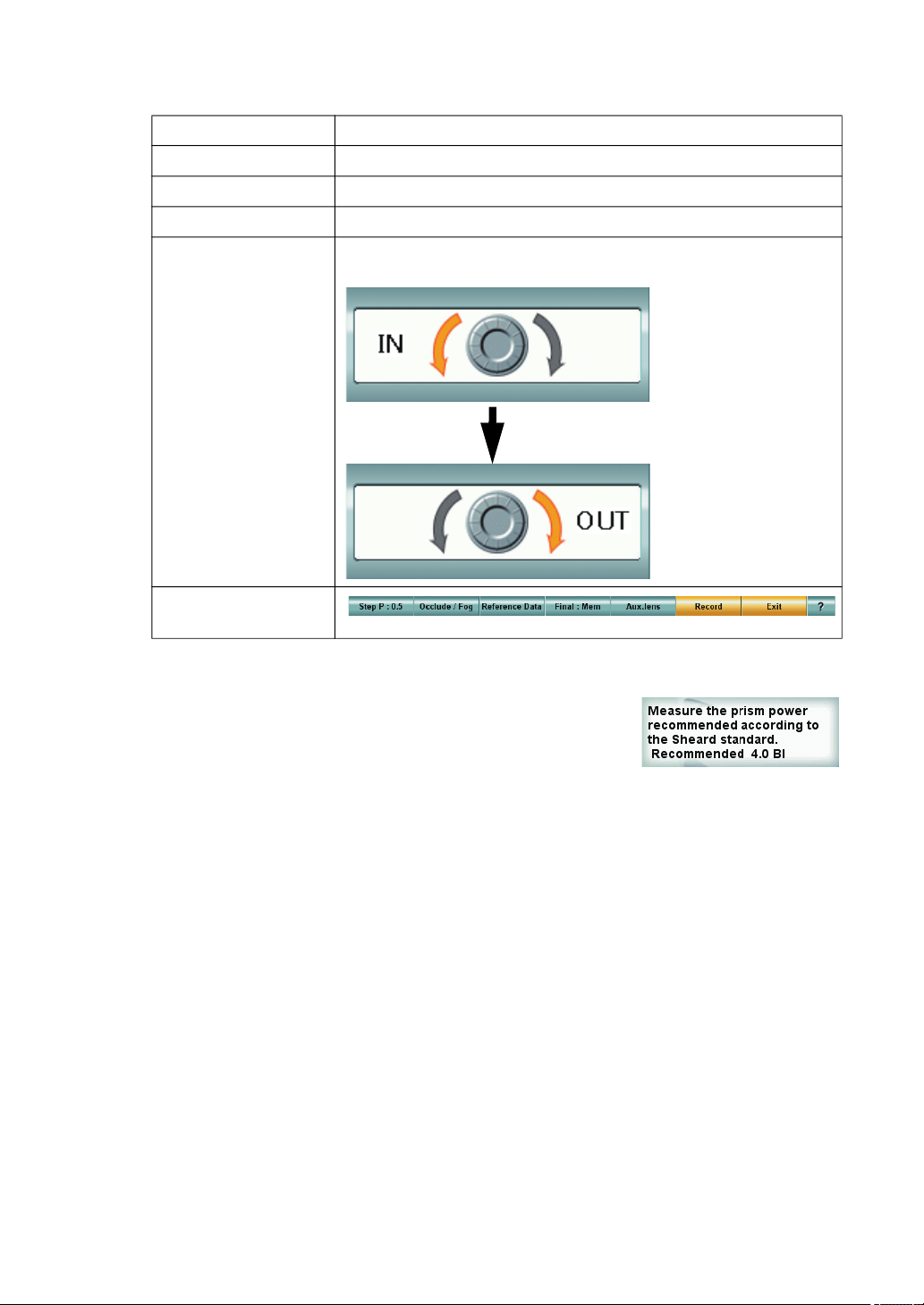
The following settings are changed automatically as shown below.
Item Description
Test eye Changed to the binocular mode.
Auxiliary lens Not set.
Dial operation mode The mode to operate "Horizontal prism" is set.
According to the initial results of the test, the following two
types are alternately displayed.
Dial Navigation
Function button
3 Measure convergence or divergence.
The program automatically judges that the system should
measure divergence if the measured heterophoria is esophoria and convergence if it is exophoira. The program
guides measurement.
Have the patient view the chart where characters are
arranged on one vertical line. Instruct the patient to respond when the blurred characters are seen or when the characters are seen on two lines. Then, turn the dial slowly in
the direction indicated by Dial Navigation.
Each time you turn the dial, the recommended prism value is changed in "Mini Help" as
shown in the right example.
If the prism value is "0" and the patient does not say "I see the blurred characters" or "I
see the characters on two lines", there are extra convergence or divergence that meets
Sheard's criteria.
The measurement is finished.
However, if the patient says "I see the blurred characters" or "I see the characters on two
lines" before the recommended prism value is "0", return the dial to the preceding status
and finish the measurement.
The recommended prism value displayed in "Mini Help" is the prism correction value
required to meet Sheard's criteria.
4 Record the result.
After the measurement, touch the [Record] button to record the result. The Sheard's criteria test is finished.
94
5. OPERATION FOR TESTS
Page 97
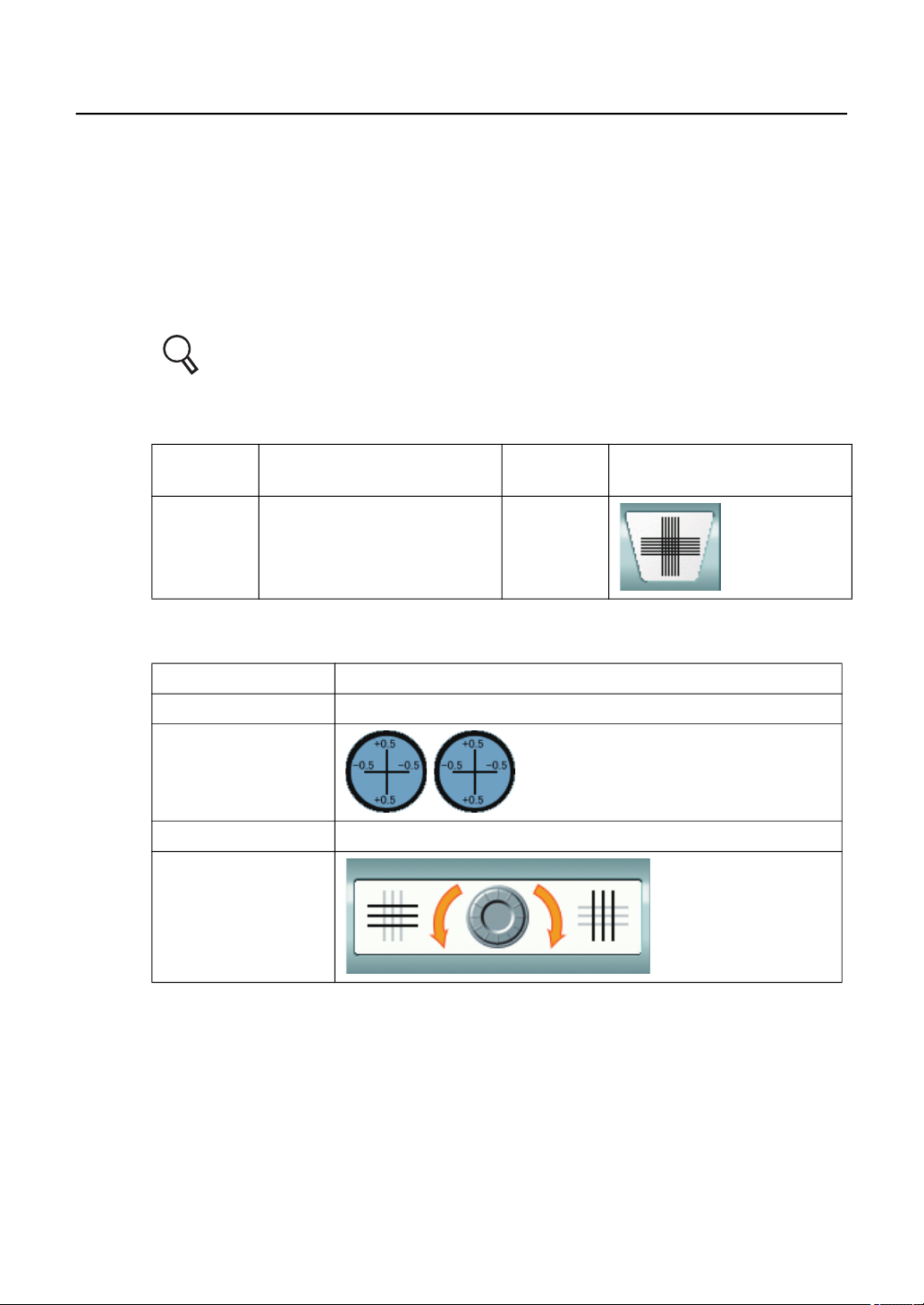
5.4 NEAR-POINT TEST
5.4.1 ADD TEST
Search for the ADD power required for near vision by using the cross cylinder lens and grid chart.
1 Select the grid chart.
To perform the ADD test, select the grid test chart icon on the chart page. Set the grid
target from the near-point card manually. Set the near-point card for the desired nearpoint distance.
For setting the near-point card targets, refer to " ADJUSTMENT OF NEARPOINT CARD" on P.130.
Example of the test chart icons on chart page
Far-point
chart
ACP-8(A)
The following settings are automatically changed as shown below.
Item Description
Test eye Changed to the binocular mode.
Auxiliary lens
Dial operation mode The mode to operate "ADD" is set.
Dial Navigation
Far-point test chart icon Near-point
chart
This test is conducted at
near only.
NC-3(E)
The cross cylinder lens of 0.5D is
set.
Near-point test chart icon
95
5. OPERATION FOR TESTS
Page 98
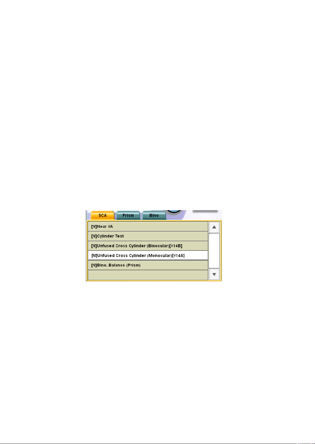
2 Search for the necessary ADD power.
Have the patient compare the vertical lines with the horizontal ones and answer which
are seen more clearly, vertical or horizontal lines.
When the patient answers "The horizontal lines are seen more clearly", turn the dial to
the left.
When the patient answers "The vertical lines are seen more clearly", turn the dial to the
right.
Adjust the ADD power until the vertical lines are seen as clearly as the horizontal ones or
until the horizontal lines are seen a little more clearly.
5.4.2 MONOCULAR ADD TEST
Search for the ADD power required for near vision of each eye by using the cross cylinder lens
and grid chart.
1 Select "[N] Unfused Cross Cylinder (Monoculer) [#14A]" from "Exam list".
To perform this test, specify the test name from "Exam list".
Press the [Shift] and [Prog] switches on the controller unit at the same time to display
"Exam list".
Press the [F/N] switch on the controller unit to display the near-point test list.
Select "[N] Unfused Cross Cylinder (Monoculer) [#14A]" in the [SCA] tab.
96
5. OPERATION FOR TESTS
Page 99
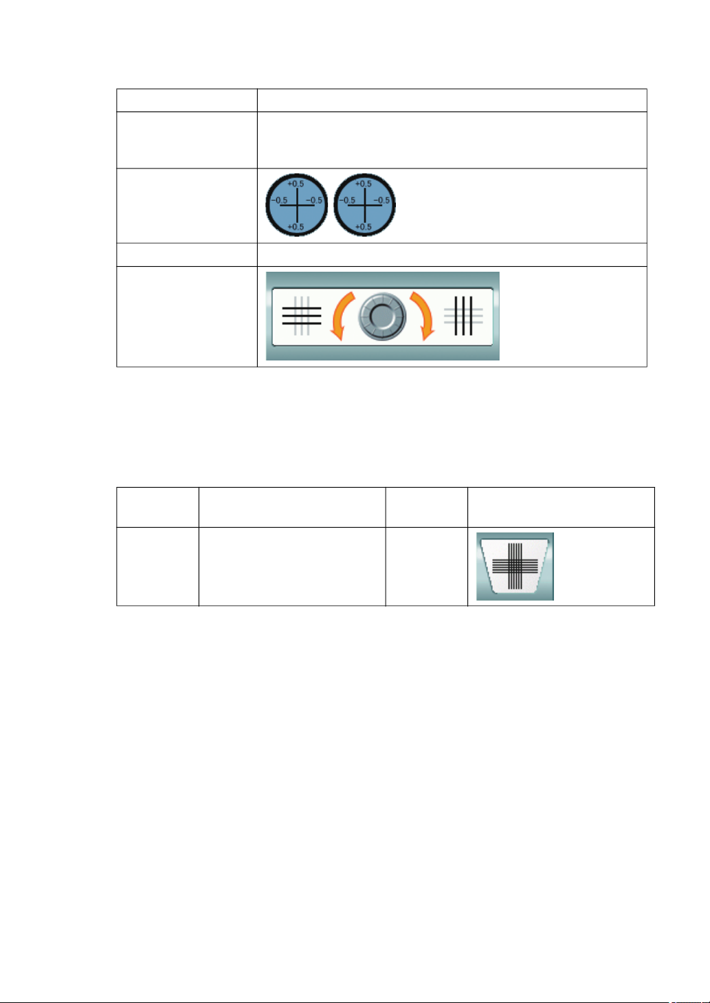
The following settings are automatically changed as shown below.
Item Description
When any other item except "binocular" is the last test object,
Test eye
Auxiliary lens
Dial operation mode The mode to operate "ADD" is set.
Dial Navigation
the last status is succeeded. When "binocular" are the last
test object, the right eye of the patient is set.
The cross cylinder lens of 0.5D is
set.
2 Set the chart.
Set the following target from the near-point card manually. Set the near-point card at the
aimed near-point distance.
Example of the test chart icons on chart page
Far-point
chart
ACP-8(A)
Far-point test chart icon Near-point
chart
This test is conducted at
near only.
NC-3(E)
Near-point test chart icon
3 Search for the necessary ADD power.
Have the patient compare the vertical lines with the horizontal ones and answer which
are seen more clearly, vertical or horizontal lines.
When the patient answers "The horizontal lines are seen more clearly", turn the dial to
the left.
When the patient answers "The vertical lines are seen more clearly", turn the dial to the
right.
Adjust the ADD power until the vertical lines are seen as clearly as the horizontal ones or
until the horizontal lines are seen a little more clearly.
97
5. OPERATION FOR TESTS
Page 100
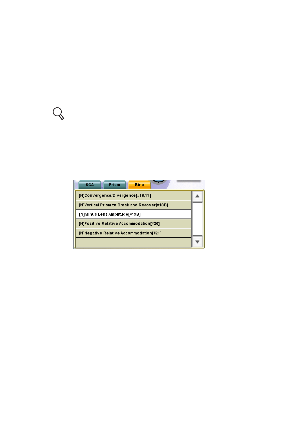
5.4.3 MINUS LENS AMPLITUDE MEASUREMENT
Place the near-point visual acuity target that meets the maximum near-point visual acuity of the
patient at 33cm in front of his/her eyes. Have the patient view this target. When adding the concave spherical lenses, check to what degree the patient can see the target clearly. In this way,
measure the accommodation power for the patient.
1 Prepare for the test.
This test must be done by using the visual acuity target that meets the maximum nearpoint visual acuity of the patient. Before this test, perform the near-point visual acuity
test.
For the visual acuity test, refer to "5.1.1 VISUAL ACUITY MEASUREMENT" on
P.55.
2 Select "[N] Minus Lens Amplitude [#19B]" from "Exam list".
To perform this test, specify the test name from "Exam list".
Press the [Shift] and [Prog] switches on the controller unit at the same time to display
"Exam list".
Press the [F/N] switch on the controller unit to display the near-point test list.
Touch the [Bino] tab and select "[N] Minus Lens Amplitude [#19B]" from the list.
98
5. OPERATION FOR TESTS
 Loading...