

TJERNLUND GPAK GAS SIDE WALL VENT SYSTEMS (GPAK-J, 1, JT, 1T DISCONTINUED) 8500370 REV. 4 0198, GPAK-J User Manual
...Page 1
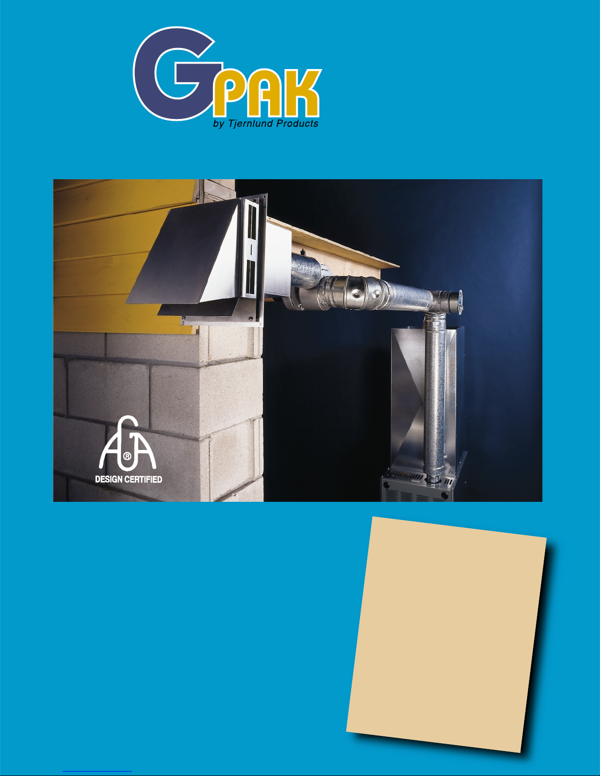
Ideal For Replacing Plastic Pipe On 80-Plus Gas Furnaces
Safety and performance
features time-proven in over
one million installations:
■ All operating components located indoors for weather
protection and easy servicing.
■ Capacities up to 250,000 BTU/hr.
■ Accommodates vent pipe runs up to 100 equivalent feet.
■ Regulated, consistent draft throughout burner cycle.
■ Built-in Fan Proving Switch interlocks with gas valve.
■ Available with 24-volt Relay or Post Purge Timer/Relay.
■ Kit includes everything needed for installation, except
vent pipe. (*GPAK* includes DC-4 Draft Control)
■ Durable, heavy-duty aluminum Vent Hood.
■ AGA design certified for gas furnaces, boilers, pool
heaters, unit heaters and commercial water heaters.
Packaged Side
Wall Vent Systems
Approved for use
with the following
brands of 80-plus
furnaces:
■ Rheem/Ruud/Weatherking
■ Evcon
■
Carrier
■ Amana
■ Heil
■ Arco Air
■
Tempstar
■ Comfortmaker
■
Armstrong
■ Heat Controller/Centur y/
Comfort Air
■ And Other Popular Brands
Page 2
TJERNLUND PRODUCTS, INC.
1601 Ninth Street White Bear Lake, MN 55110-6794
Phone: 612.426.2993 800.255.4208 Fax: 612.426.9547
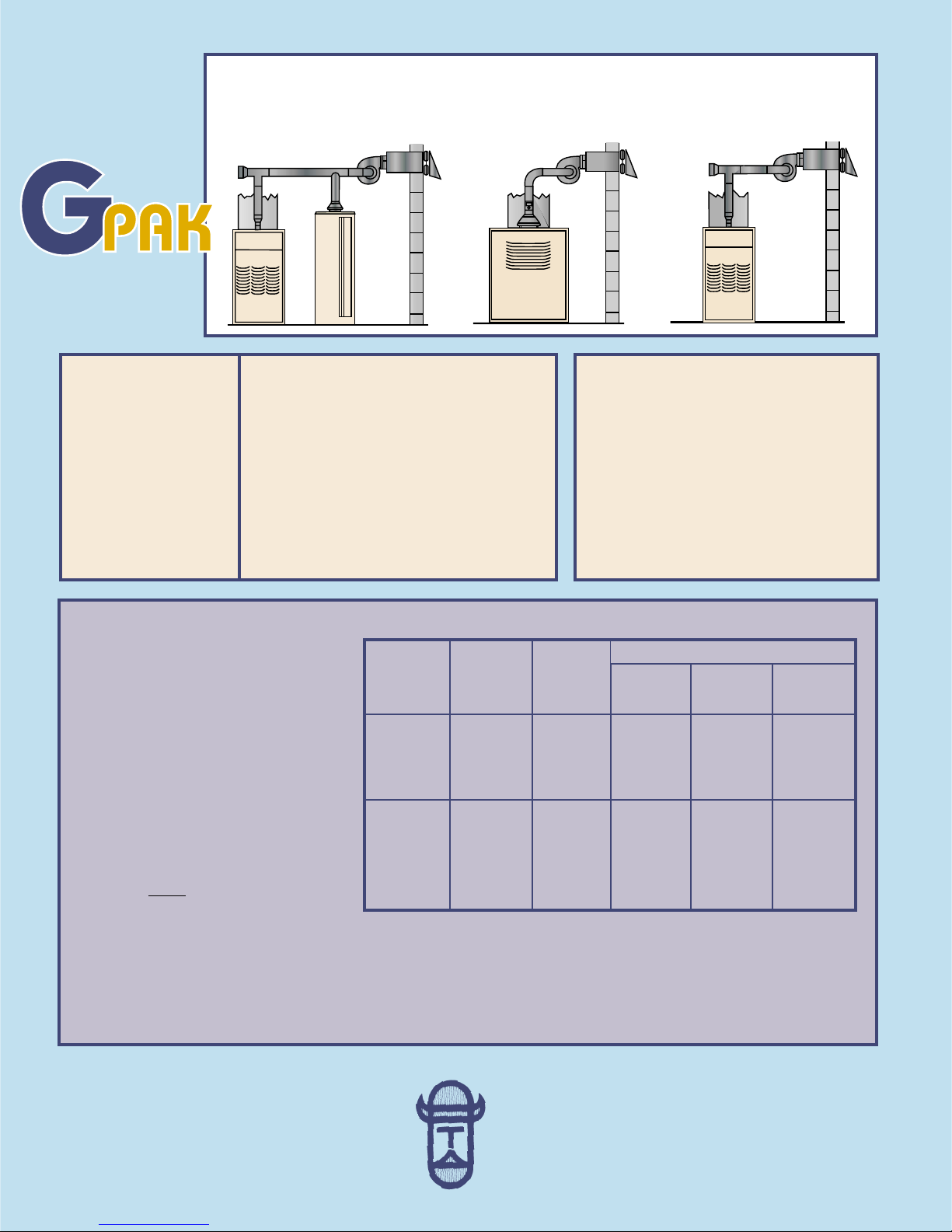
TYPICAL APPLICATIONS
Fan Assisted Furnace
& Water Heater
Commercial Water Heaters
& Residential Boilers
Fan Assisted
Furnaces
NOTES:
1. If the appliance flue outlet is greater than
4'', install a tapered reducer after the
draft hood, draft diverter or barometric
draft control, reducing vent pipe diameter to 4''. All vent pipe from the appliance
to the Power Venter may be 4''.
2.Table is based on straight vent pipe. 90
degree elbows are equivalent to 6 feet of
straight vent pipe.
3.Deter mine maximum pipe length from
type of equipment being vented and
GPAK Model.
Column A pipe runs
over 30 linear feet should use Type
“B” vent. Column B & C pipe runs
over 15 linear feet should use Type
“B” vent.
GPAK
MOTOR
SPECIFICATIONS
ELECTRICAL DATA
COMPONENT DESCRIPTIONS
GPAK-J, 1
Relay — 24/115V Switching Relay
Fan Proving Switch — 3FLA, 18 LRA@120 VAC
GPAK-JT, 1T
Timer/Relay — 24/115V Switching Relay, 45
Second Fixed Delay
Fan Proving Switch — 3FLA, 18 LRA@120 VAC
MODEL SELECTION TABLE
Packaged
Side Wall
Vent Systems
INSTALLATION OVERVIEW
1. Determine point of termination and
install V ent Hood.
2. Attach perforated strap to vibration
isolation mounts on Power Venter and
install adjacent to Vent Hood.
3. Connect outlet flue of heater(s) to inlet
of Power Venter. Connect Power Venter
outlet to Vent Hood.
4. Interlock Relay or Timer/Relay and Fan
Proving Switch with burner.
100'
100'
100'
45'
100'
100'
100'
87'
40'
60'
60'
60'
60'
60'
60'
60'
N/A
N/A
60'
60'
N/A
N/A
60'
60'
60'
N/A
N/A
Maximum Total Vent Pipe Length
Models
GPAK-J
GPAK-JT
*GPAK-JT*
GPAK-1
GPAK-1T
*GPAK-1T*
Vent Pipe
Diameter
4''
4''
BTU/hr
Input
45,000
75,000
100,000
120,000
100,000
120,000
150,000
200,000
250,000
*40,000 ATM
Atmospheric Fan Assisted +Column B
A B C
DISTRIBUTED BY:
Copyright © 1997 Tjernlund Products Inc. All rights reserved P/N: 850-0370 Rev.4, 1/98
Volts
Hertz
RPM
Watts
Amps
Therm. Prot.
115
60
3000
95
1.26
Yes
4. Column C allows for up to a 40,000 BTU/hr. input atmospheric water heater common vented with a fan assisted
appliance from column B.
5. All reducers and vent pipe are to be supplied by the installer and are available from your local heating wholesaler.
6. Models with asterisks, e.g. *GPAK-JT*, include a 4'' draft control and are authorized for use on furnaces eligible for the
HTPV Corrective Action Program.Installations for the HTPV Program must use Type “B” vent.
7. Also available, *GPAK-1TR* for use with Rheem, Ruud, Weatherking and Heat Controller brands.
®
 Loading...