

Page 1
Copyright © 2007, Tjernlund Products, Inc. All rights reserved. P/N 8504143
REV. 9/07
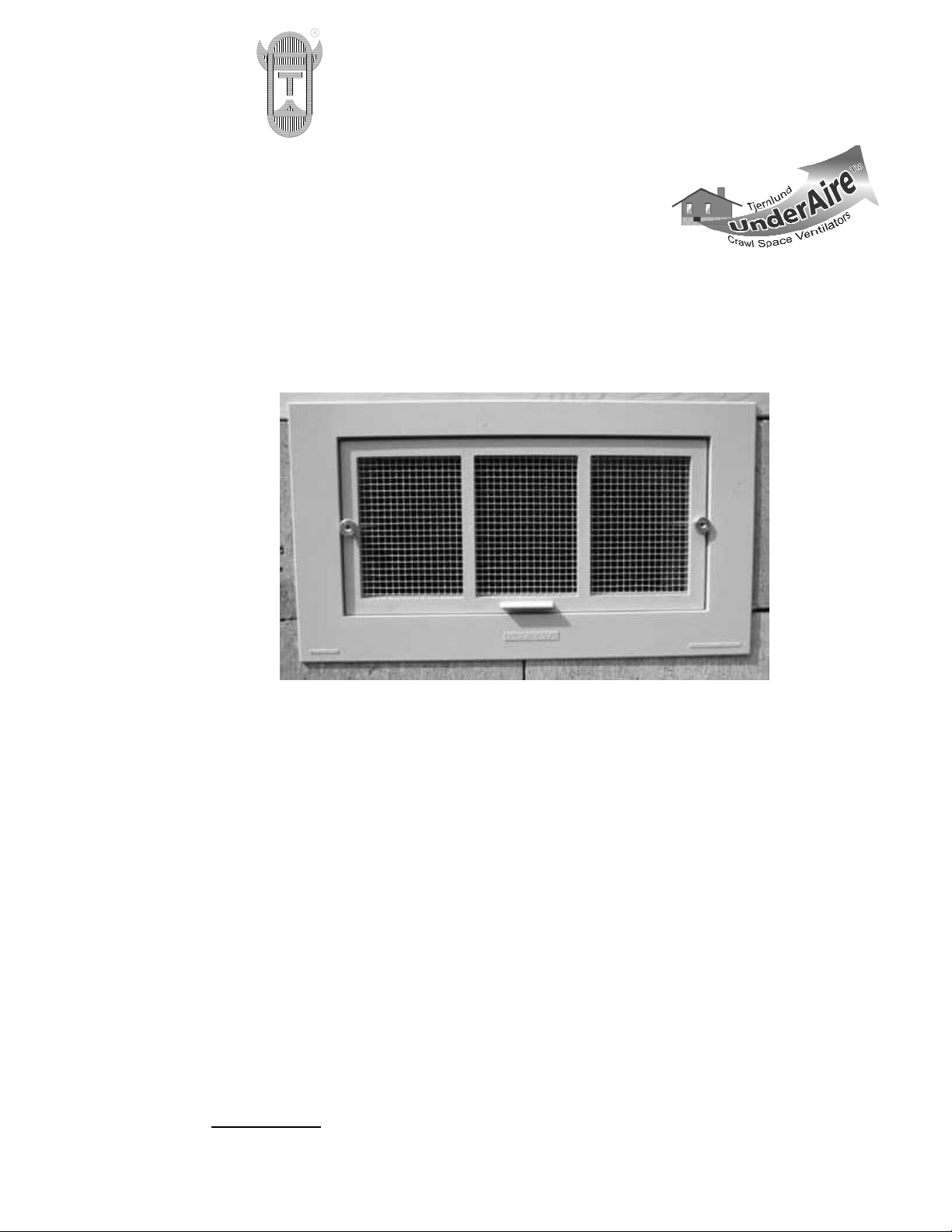
MODEL FV1 PASSIVE FOUNDATION VENT
INSTALLATION INSTRUCTIONS
SUGGESTED TOOLS AND MATERIALS
• Safety glasses with side shields
• Work gloves
• Tape measure
• 7/16" wrench
• Caulk gun
• Silicone caulk
• Level
IF REMOVING OLD VENTS
• Hammer
• Pry bar
• Mason chisel
MATERIALS INCLUDED
Gray vent faceplate
Screen door
White sealer/winter door
Black backer bar
2 - 9” Threaded rods
2 - ¼” Lock nuts
2 - ¼” Brass knurled nuts
2 - ¼” Wing nuts
IMPORTANT: ALWAYS FOLLOW LOCAL BUILDING CODES.
TJERNLUND PRODUCTS, INC.
1601 Ninth Street • White Bear Lake, MN 55110-6794
PHONE (800) 255-4208 • (651) 426-2993 • FAX (651) 426-9547
Visit our web site • ww w.tjernlund.com
Page 2
INSTALLATION
IMPORTANT:
ALWAYS FOLLOW YOUR LOCAL BUILDING CODES.
1. Measure width and height of opening to verify the FV1 faceplate will overlap the opening by at least ¼" or more on all
four sides.
2. If replacing an existing vent, remove the mortar that secures the vent to the foundation using a hammer, flat pry bar
and/or large masonry chisel.
CRAWL SPACE VENT INSTALLATION (DIAGRAM A)
1. Once it is verified that the faceplate fits flush with the sill plate and foundation, caulk the backside of the faceplate
with ample silicone caulk to insure a quality seal.
2. Put one lock nut on each of the threaded rods.
3. Reach inside through the faceplate opening and screw each of the threaded rods through the inserts of the faceplate
toward the outside of the foundation until the rods protrude at least 5/8".
4. Tighten the lock nuts on inside of threaded rod with 7/16" wrench. DO NOT over tighten.
5. Reach through faceplate opening with the backer bar in hand and place backer bar on threaded rods. Install the wing
nuts on each of the threaded rods behind the backer bar and finger tighten until the bar is tight against the inside wall
and begins to bend slightly. This will apply tension to allow for consistent sealing of the caulk that was applied to the
back of the faceplate.
6. Place the screen door on the unit by aligning the screen door holes with the protruding ends of the threaded rods and
hand tighten the knurled nuts to the screen door.
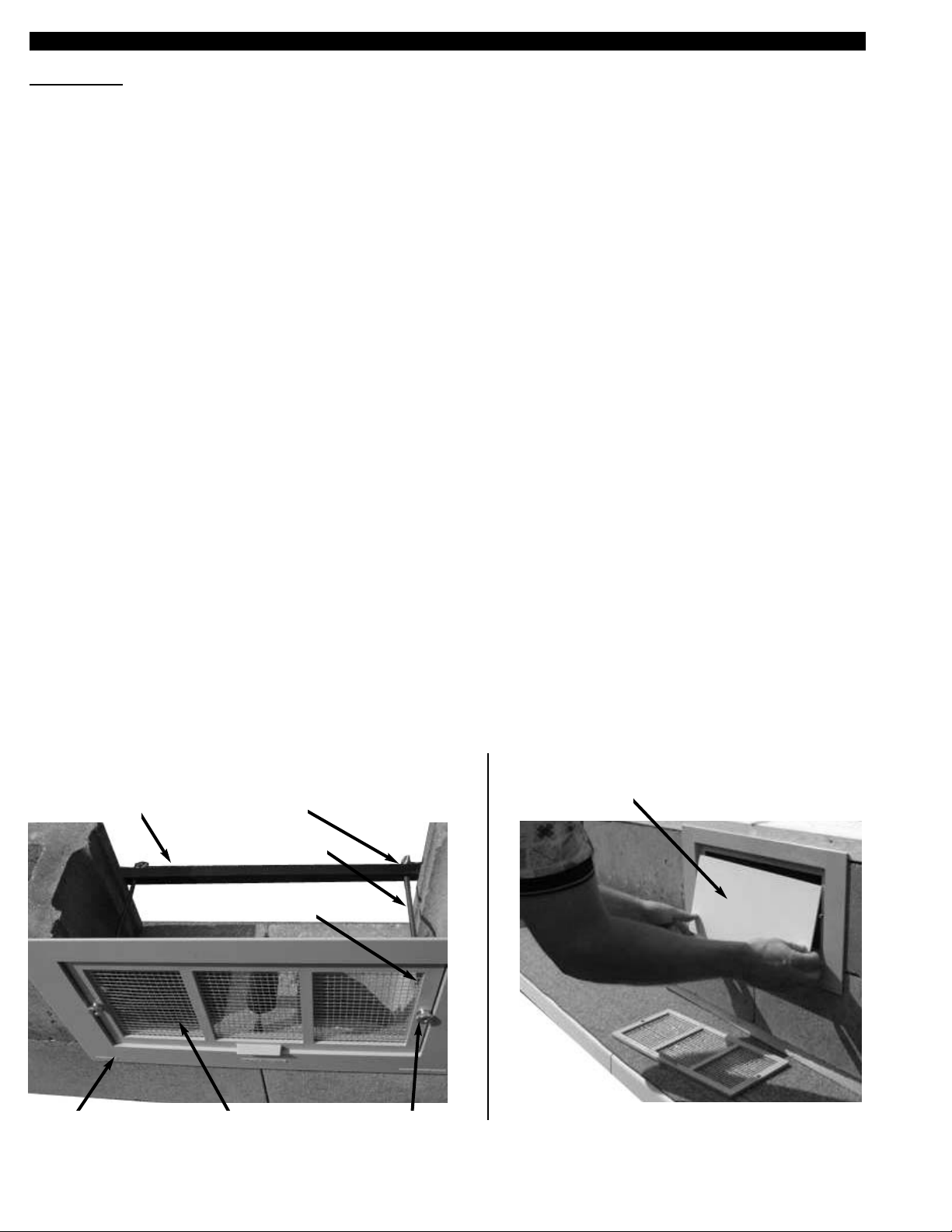
WINTER DOOR INSTALLATION (DIAGRAM B)
Store the winter door in a convenient place for heating season installation. To install the winter door, unscrew the
knurled nuts and place the winter door behind the screen door. Replace the screen door and retighten the knurled
nuts.
Wing nut(s)
Faceplate Screen door
Lock nut(s)
Threaded rod(s)
Backer bar
Knurled nut
Winter door
DIAGRAM A DIAGRAM B
Page 3

DIMENSIONS
TROUBLESHOOTING INSTALLATION PROBLEMS
VENT FACEPLATE DOES NOT FIT UNDER SIDING
OPTION 1: Trim the FV1 faceplate. The backside of the faceplate has pre-scored lines to assist in trimming. This
area can be trimmed using simple tools (utility knife, pliers, hacksaw) to customize the height of the faceplate. Width
trimming is usually not needed, but may be done using cutting tools made to cut ABS materials.
OPTION 2: On some homes the siding needs to be pried away from the sill plate and the foundation by a 1/8” or 1/4”
for the vent faceplate to slide under and up to the sill plate. To do this, one may use a pry bar or shims to pry the siding away from the framing and foundation. Do so with caution. Siding can be very brittle. Always secure all
loosened areas once installation is complete. If the siding is pried away and the vent still will not fit check for nails,
screws, or other obstructions.
SILL PLATE OVERHANGS THE FOUNDATION AND THE VENT DOES NOT FIT FLUSH AGAINST FOUNDATION
If the sill plate overhangs or is recessed from the foundation, use a 1x2, 2x2 or 2x4 piece of lumber cut to the length of
the opening of the foundation and attach the lumber to the sill plate so that it is flush with the foundation. This now
becomes the sill plate to which the faceplate can be mounted.
FACEPLATE IS FLUSH, THREADED RODS ARE IN THE FACEPLATE BUT THE THREADED RODS DO NOT GO
THROUGH THE PRE-DRILLED HOLES IN THE BACKER BAR; THE WING NUTS CANNOT BE ATTACHED
The included threaded rods are 9” long. These will accommodate foundation block wall widths of up to 8”. For buildings
with thicker foundations, substitute the included rod with an 1/4” diameter rod cut to the length necessary for installation.
NOTE: At least 1” of clearance is needed beyond the width of the foundation wall in order for the vent screen, winter
door, and backer bar to fit properly.
VENT OPENING IS BIGGER OR SMALLER THAN THE FV1 FACEPLATE
A frame can be built for openings too large for the faceplate or the faceplate can be cut to size for a smaller
opening.
FACEPLATE INSTALLATION
7"
10"
19 1/2"
14 1/2"
18"
2" 2"
1/2"
1"
9"
8061006 9/5/07
Page 4

COMPANION VENTILATION PRODUCTS
UNDERAIRETMCRAWL SPACE
VENTILTORS
MODEL V1
One fan and small faceplate for
ventilation openings through brick
foundations. (Requires switch or
dehumidistat to activate. Multiple
ventilators may be controlled by a
single switch or dehumidistat).
Includes thermostat.
MODEL V1D
One fan and large faceplate sized
for ventilation openings through
block foundations. Includes thermostat, dehumidistat and
pre-wired 6’ power cord.
MODEL V2D
Two fans and large faceplate sized
for ventilation openings through
block foundations. Includes thermostat, dehumidistat and prewired 6’ power cord.
Fan powered crawl space ventilation quickly reduces
moisture helping to protect both home and occupants.
 Loading...