

Page 1
Copyright © 2000, Tjernlund Products, Inc. All rights reserved. P/N 8504090
REV. 11/00
RECOGNIZE THIS SYMBOLAS AN INDICATION OF IMPORTANT SAFETY INFORMATION!
THESE INSTRUCTIONS ARE INTENDED AS AN AID TO QUALIFIED, LICENSED
SERVICE PERSONNEL FOR PROPER INSTALLATION, ADJUSTMENT AND
OPERATION OF THIS UNIT. READ THESE INSTRUCTIONS THOROUGHLY
BEFORE ATTEMPTING INSTALLATION OR OPERATION. FAILURE TO FOLLOW
THESE INSTRUCTIONS MAY RESULT IN IMPROPER INSTALLATION, ADJUSTMENT, SERVICE OR MAINTENANCE POSSIBLY RESULTING IN FIRE, ELECTRICAL SHOCK, CARBON MONOXIDE POISONING, EXPLOSION, PERSONAL
INJURY OR PROPERTY DAMAGE.
!
DO NOT DESTROY. PLEASE READ CAREFULLY AND KEEP IN
A SAFE PLACE ON JOB SITE FOR FUTURE REFERENCE.
MODELS
FSAD-8
FSAD-10
FSAD-12
VSAD-8
VSAD-10
VSAD-12
AUTO-DRAFT
®
VENT SYSTEMS
FOR NATURAL GAS, LP OR OIL-FIRED
HEATING APPLIANCES
TJERNLUND PRODUCTS, INC.
1601 Ninth Street • White Bear Lake, MN 55110-6794
PHONE (800) 255-4208 • (651) 426-2993 • FAX (651) 426-9547
Visit our web site • ww w.tjernlund.com
Auto-Draft® Venters are tested and Listed to UL
Standard 378 for Draft Equipment
Auto-Draft® Venters are tested and Listed to
CAN3-B255-M81 for Mechanical Flue-Gas Exhausters /
CAN-B140-M87 Sec. 19 for requirements for through
the wall venting systems used with oil-fired appliances
Page 2
TABLE OF CONTENTS
PAGE(S)
AUTO-DRAFT® VENTER DESCRIPTION ................................................................................................................. 1
DIMENSIONS AND SPECIFICATIONS ........................................................................................................................ 1
AUTO-DRAFT® VENTER FAN PERFORMANCE CURVES..........................................................................................2
INSTALLATION RESTRICTIONS & CAUTIONS........................................................................................................... 3
INSTALLER RESTRICTIONS & CAUTIONS IN FRENCH CANADIAN ..................................................................... 3-4
AUTO-DRAFT® VENTER TERMINATION CLEARANCES FOR CANADIAN & U.S. INSTALLATIONS ................... 4-6
AUTO-DRAFT® VENTER INSTALLATION ................................................................................................................ 6-8
PSA-1 FAN PROVING SWITCH INSTALLATION ......................................................................................................... 8
WIRING .....................................................................................................................................................................8-16
PSA-1 SAFETY INTERLOCK AND DRAFT ADJUSTMENT SET-UP PROCEDURE ..............................................16-17
SAFETY INTERLOCK TEST.........................................................................................................................................17
COMBUSTION AIR ...................................................................................................................................................... 17
MAINTENANCE ......................................................................................................................................................17-18
TROUBLESHOOTING .................................................................................................................................................18
HOW TO OBTAIN SERVICE & LIMITED WARRANTY ..........................................................................................18-19
REPLACEMENT PARTS ..............................................................................................................................................19
Tjernlund Products welcomes your comments and questions. Call us at 800-255-4208, Fax 651-426-9547, Email us at
fanmail@tjfans.com or write to: Customer Service, Tjernlund Products, Inc., 1601 Ninth Street, White Bear Lake, MN 55110-6794.
DESCRIPTION
The Tjernlund Auto-Draft® vent systems are designed to side wall or vertically vent natural gas, LP-gas and oil-fired heating systems.
All models are supplied with the model PSA-1 Fan Proving Switch which will disable the burner(s) if a venting malfunction should
occur. The Auto-Draft® may be used on positive or negative pressure rated chimneys because the fan creates a negative pressure
throughout the entire venting system. The Auto-Draft® Venter must always be installed outdoors at the vent system termination.
Refer to heating appliance manufacturer’s instructions regarding specific venting requirements.
COMPLETE AUTO-DRAFT® VENT SYSTEM SOLUTIONS
This installation manual does not contain any system design documentation. Installation and use of Tjernlund controls like the CPC-2
Constant Pressure Controller, EXP-4 Appliance Interlock Expansion boards or MAC-4 Multiple Appliance Controller are not covered by
this manual. Please refer to those accessory installation manuals.
DIMENSIONS AND SPECIFICATIONS
1
115
1725
5.0
47
21.32
22
559
19 3/4
500
9
228
7 7/8
200
15
381
18 3/4
475
No
No
115
1725
7.2
97
43.99
25
635
23
585
11 1/8
283
9 7/8
251
20
508
24 3/4
629
No
No
208-230
1725
9.3
138
62.59
28 3/4
730
26 1/2
674
13 5/8
348
11 7/8
302
26 3/16
665
31 3/4
806
No
No
3x208-230
2440
1.5
48
21.77
22
559
19 3/4
500
9
228
7 7/8
200
15
381
18 3/4
475
Yes (1)
3x208-230
2300
3.4
101
45.80
25
635
23
585
11 1/8
283
9 7/8
251
20
508
24 3/4
629
Yes (1)
Yes with
VFD
Yes with
VFD
3x208-230
2070
6.2
140
63.49
28 3/4
730
26 1/2
674
13 5/8
348
11 7/8
302
26 3/16
665
31 3/4
806
Yes (1)
Yes with
VFD
Centrifugal Impeller
FSAD-8 FSAD-10 FSAD-12 VSAD-8 VSAD-10 VSAD-12
(1) Must use a Tjernlund VFD which includes Soft Start.
mm
mm
in
mm
in
mm
in
mm
in
mm
in
in
kgs
lbs
A
VAC
A
B
C
D
E
F
Dimensions
Weight
Amps
RPM
Voltage
MODEL
Motor Soft Start Required
Variable Speed Motor
Fan Type
Figure Cpe3 5/2/01
Power Rating
kW
0.19
hp 1/4
0.37
1/2
0.25
1/3
1.12
1 1/2
0.75
1
1.49
2
See “Wiring” for procedure to
confirm proper VSAD rotation.
Page 3

AUTO-DRAFT® VENTER FAN PERFORMANCE CURVES
Auto-Draft® Venter performance was independently tested by an accredited AMCA certified testing facility.
Selection of an Auto-Draft® Venter involves determination of the maximum volume of gas to be handled, the density of the gas and
the maximum static pressure which the fan must overcome.
Variable speed VSAD-Series Venters can operate at virtually any point to the left of the performance curve. For Side Wall applica-
tions add 0.50” W.C. to vent system resistance to accommodate the effects of wind loading.
Auto-Draft® Venter performance needs to be derated from 70
O
F performance curves to anticipated flue gas temperatures.
Please feel free to contact us for application and model selection assistance by calling 800-255-4208 or email us at
fanmail@tjfans.com. Vent layout or other information can be faxed to 651-426-9547.
2
CFM (STD AIR 70 DEGREES F)
STATIC PRESSURE IN. W.C.
VSAD−8
FSAD−8
CFM (STD AIR 70 DEGREES F)
STATIC PRESSURE IN. W.C.
VSAD−12
FSAD−12
CFM (STD AIR 70 DEGREES F)
STATIC PRESSURE IN. W.C.
VSAD−10
FSAD−10
Page 4
3
INSTALLATION RESTRICTIONS
Failure to install, maintain and/or operate the Auto-Draft® Venter in accordance with manufacturer's instructions may result
in conditions which can produce bodily injury and property damage.
The Auto-Draft® Venter must be installed by a qualified installer in accordance with these instructions and all local codes or in their
absence in accordance with the latest edition of The National Fuel Gas Code (NFPA 54), NFPA 211 or 31 when applicable, the latest
edition of the National Electrical Code (NFPA 70) and the Occupational Safety and Health Act (OSHA) when applicable. In the
absence of local codes in Canada, installations must comply with the Canadian Electrical Code (CSA Std 22.1 ), the latest edition of
the Natural Gas Installation Code (CAN/CGA-B149.1), the Propane Installation Code (CAN/CGA-B149.2) and the Installation Code for
Oil Burning Equipment (CSA Std B139-M91).
Improper installation can create a hazardous condition such as an explosion, fire, electrical shock or carbon monoxide poisoning
resulting in property damage, personal injury or death.
1. The Auto-Draft® Venter may only be installed on natural gas, LP-gas or oil-fired heating appliance systems. The Auto-Draft® Venter
is not suitable for use on condensing equipment in Canada.
2. The Auto-Draft® Venter was tested with exit flue gas temperatures of 575
O
F (300OC).
3. The Auto-Draft® Venter may not be installed on incinerators, incinerating toilets or solid-fuel burning appliances.
4. The Auto-Draft® Venter must always be installed at the vent system termination, whether terminating through the roof or side wall.
It can only be mounted with motor shaft vertical or horizontal to guarantee proper operation of Tilt Switch which cuts out power to
motor when Venter housing is opened.
5. The Auto-Draft® Venter shall not be installed on an appliance with an automatic valve having a manual opener unless the manual
opener has been rendered inoperative or the automatic valve has been replaced with a valve not equipped with a manual opener.
6. Auto-Draft® Venters not utilizing the Tjernlund CPC-2 Constant Pressure Control may only be installed on appliances equipped
with a draft hood, draft diverter or barometric draft control.
IONS
INSTALLER CAUTIONS
Disconnect the power supply when making wiring connections or when working around the fan impeller and motor. Failure
to do so can result in electrical shock, personal injury, death or property damage.
1. The model PSA-1 Fan Proving Switch provided must be interlocked with the heating appliance burner(s).
2. Plan the vent system so that the code required clearances are maintained from plumbing, wiring and combustibles.
3. Make certain the power supply is adequate for Auto-Draft® Venter motor requirements. Do not add the Auto-Draft® Venter to a
circuit where the total load is unknown.
4. The installer must verify that the appliance on which the Auto-Draft® Venter will be installed is in a safe operating condition.
Consult appliance manufacturer’s Instructions for details.
5. The appropriate Tilt Switch, which cuts out power to motor when housing is opened, must be wired into the safety circuit depending
on horizontal or vertical orientation of the Auto-Draft® Venter. Refer to wiring instructions and diagrams for details.
6. Auto-Draft® Venter housing is single wall. Standard clearances to combustibles must be maintained. Optional wall and roof mount
kits which maintain clearances to combustibles are available from Tjernlund.
7. VSAD Series Venters must use appropriate Tjernlund VFD model.
LIMITATIONS CONCERNANT L'INSTALLATION
Le fait d'installer, d'entretenir ou d'utiliser le ventilateur de tirage Auto-Draft® d'une manière non conforme aux instructions
du fabricant risque de provoquer des blessures et des dégâts matériels.
Le ventilateur de tirage Auto-Draft® doit être installé par un installateur qualifié, conformément à ces instructions et à tous les règlements locaux. En l'absence de règlements locaux au Canada, les installations doivent se conformer au Code canadien de l'électricité
(CSA Std 22.1 ), à la dernière édition du Code d'installation du gaz naturel (CAN/CGA-B149.1), du Code d'installation du propane
(CAN/CGA-B149.2) et du Code d'installation des appareils de combustion au mazout (CSA Std B139-M91).
Une installation incorrecte risque de créer une situation dangereuse, telle une explosion, un incendie, des chocs électriques ou un
empoisonnement au monoxyde de carbone, entraînant des dégâts matériels et des blessures graves, voire mortelles.
1. Le ventilateur de tirage Auto-Draft® ne doit être installé qu'avec des appareils de chauffage au gaz naturel, au gaz de pétrole
liquéfié ou au mazout. Le ventilateur de tirage Auto-Draft® ne doit pas être installé sur condensing equipment au Canada.
Page 5
4
2. La température des gaz de combustion ne doit pas dépasser 575 °F (300 °C) au niveau de l'orifice d'admission du ventilateur de
tirage Auto-Draft®.
3. Le ventilateur de tirage Auto-Draft® ne doit pas être installé sur des incinérateurs, des cuvettes sanitaires à incinération ou des
appareils brûlant un combustible solide.
4. Le ventilateur de tirage Auto-Draft® doit toujours être installé en bout du système d'évacuation, que ce soit au niveau du toit ou
d'un mur. Son montage exige que l'axe du moteur soit vertical ou horizontal pour assurer un fonctionnement correct du contacteur
à basculement qui coupe l'alimentation en cas d'ouverture du boîtier du ventilateur de tirage.
5. Le ventilateur de tirage Auto-Draft® ne doit pas être installé sur un appareil équipé d'une vanne automatique avec surpassement
manuel d'ouverture, sauf si ce dernier a été neutralisé ou si la vanne automatique a été remplacée par une vanne sans surpassement manuel.
6. Les ventilateurs Auto-Draft® qui n'utilisent pas le système de régulation à pression constante CPC-2 ne doivent être installés que
sur les appareils équipés d'un coupe-tirage, d'une hotte de tirage ou d'un régulateur barométrique de tirage.
PRÉCAUTIONS D'INSTALLATION
Coupez l'alimentation électrique avant d'effectuer le raccordement ou lorsque vous travaillez à proximité du moteur et du
ventilateur. L'inobservation de cette consigne risque d'entraîner des chocs électriques, des blessures graves, voire
mortelles et des dégâts matériels.
1. Le ou les brûleurs doivent être électriquement asservis au détecteur d'activation du ventilateur.
2. Arrangez le système d'évacuation de manière à respecter les dégagements réglementaires requis vis-à-vis des tuyauteries, des
câblages électriques et des matériaux adjacents.
3. Assurez-vous que l'alimentation électrique dispose d'une puissance suffisante pour alimenter le moteur du ventilateur de tirage
Auto-Draft® . Ne pas installer le ventilateur de tirage Auto-Draft® dans un circuit dont la charge totale est inconnue.
4. L'installateur doit vérifier que l'appareil sur lequel le ventilateur de tirage Auto-Draft® est installé est en bon état de fonctionnement.
Consultez les instructions du fabricant de l'appareil pour plus de détails.
5. Un contacteur à basculement, qui coupe l'alimentation électrique du moteur en cas d'ouverture du boîtier, doit être raccordé au circuit de sécurité. Utilisez le contacteur correspondant à la position de montage, horizontale ou verticale, du ventilateur de tirage
Auto-Draft® . Reportez-vous aux instructions et schémas de câblage pour de plus amples informations
6. Le boîtier du ventilateur de tirage Auto-Draft® est un boîtier à simple paroi. Les dégagements standard vis-à-vis des matériaux
combustibles doivent être respectés. Des ensembles optionnels de montage au toit ou au mur sont disponibles auprès de Tjernlund.
7. Vu du grillage d'échappement de l'Auto-Draft®, le ventilateur doit tourner dans le sens antihoraire, (voir schéma x).
8. Important: la charnière du boîtier doit être orientée vers le bas en cas de montage mural. Faites coïncider les goujons de la plaque
de montage avec les trous dans la base du ventilateur de tirage Auto-Draft® et attachez l'Auto-Draft® à la plaque de montage
à l'aide des écrous fournis, (voir schéma G).
9. Le détecteur d'activation du ventilateur PSA-1 doit être monté de sorte que son diaphragme soit vertical. Reportez-vous à la
section "Installation du détecteur d'activation du ventilateur PSA-1".
10. Les ventilateurs de tirage de la gamme VSAD doivent utiliser le modèle de VFD Tjernlund approprié.
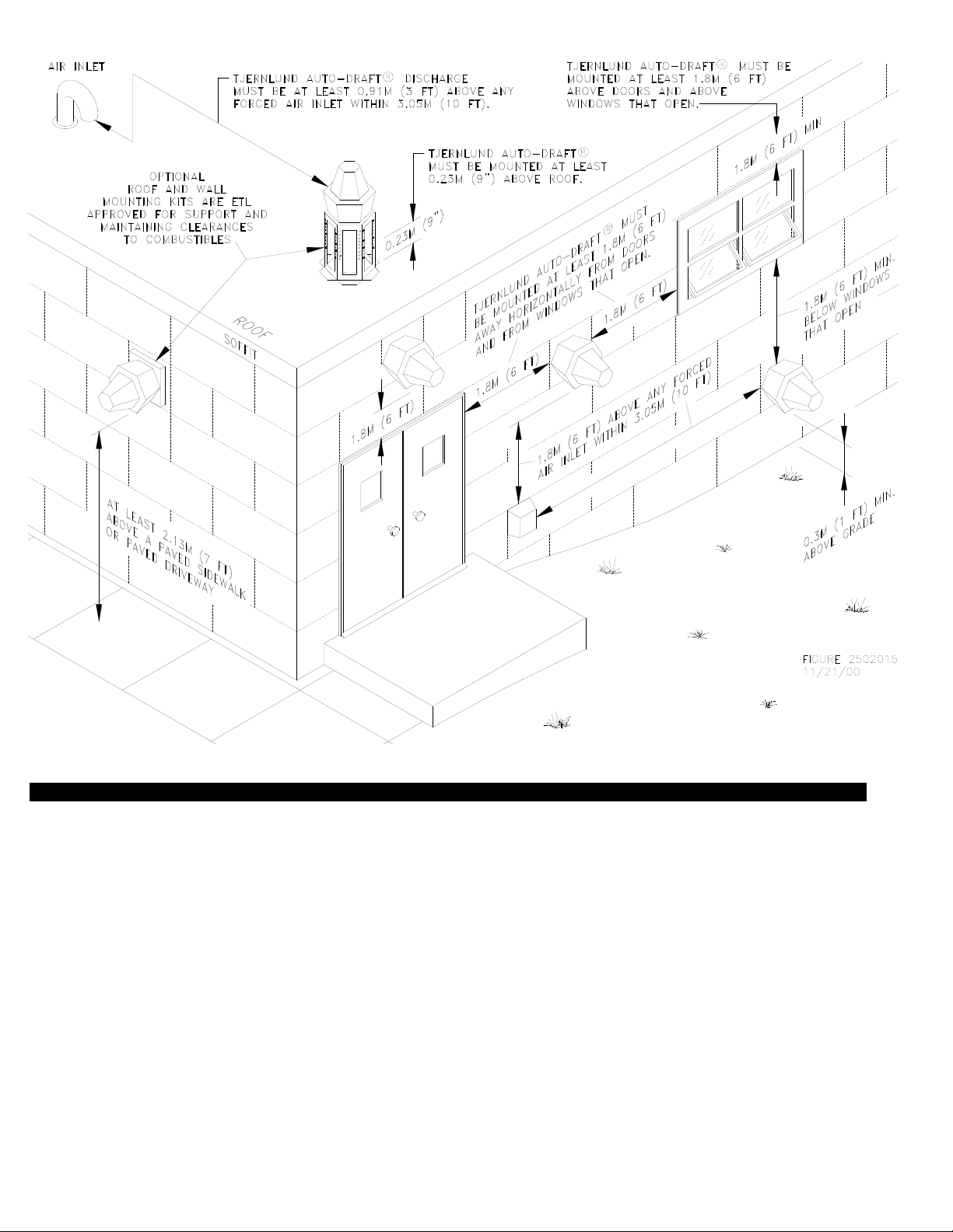
AUTO-DRAFT® VENTER TERMINATION CLEARANCES FOR CANADIAN INSTALLATIONS
In the absence of local codes in Canada, installations must comply with the latest edition of the Natural Gas Installation Code
(CAN/CGA-B149.1), the Propane Installation Code (CAN/CGA-B149.2), the Installation Code for Oil Burning Equipment (CSAStd
B139-M91) or as follows, (See Diagram A).
• A venting system shall not terminate underneath a veranda, porch, or deck, or above a paved sidewalk or a paved driveway
that is located between two buildings, and that serves both buildings.
• The exit terminals of mechanical draft systems shall not be less than 2.13m (7ft) above grade when located adjacent to a paved
sidewalk or driveway.
• A venting system shall not direct flue gases towards brickwork, siding, or other construction, in such a manner that may cause
damage from heat or condensate from the flue gases.
• A venting system shall not direct flue gases so as to jeopardize people, overheat combustible structures, or enter buildings.
A
venting system shall not terminate within 1.8 m (6ft) of the following:
• A window, door or mechanical air supply inlet of any building, including soffit openings
• A gas service regulator vent outlet
• A combustion air inlet
• A property line
• A direction facing combustible materials or openings of surrounding buildings
A
venting system shall not terminate within 1m (3ft) of the following:
• Above a gas meter/regulator assembly within 1m (3ft) horizontally of the vertical centreline of the regulator
• A oil tank or an oil tankfill inlet
A
venting system shall not terminate within .3m (1ft) of the following:
• Above grade level or any surface that may support snow, ice, or debris
Page 6
5
TERMINATION CLEARANCES FOR U.S. INSTALLATIONS
The Auto-Draft® Venter base must be a minimum of 9” above a roof. Optional roof and wall mounting kits are available from Tjernlund.
CODE REQUIREMENTS
Terminate the Auto-Draft® Venter so that proper minimum clearances are maintained as cited in the latest edition of the National Fuel
Gas Code (NFPA 54), NFPA 211 or 31 when applicable, (See Diagram B):
• Not be less than 7 feet above grade when located adjacent to public walk ways.
• At least 3 feet above any forced air inlet located within 10 feet.
• At least 4 feet below, 4 feet horizontally from or 1 foot above any door, window or gravity air inlet into any building.
• At least 1 foot above grade.
• So that the flue gases are not directed so as to jeopardize people, overheat combustible structures or enter buildings, and
• Not less than 2 feet from an adjacent building.
INS
DIAGRAM A
CANADA
Page 7

6
INSTALLATION OF THE AUTO-DRAFT® VENTER
The Auto-Draft® Venter is designed to fit any type of nominal 8”, 10” or 12” diameter vent pipe. Vent pipe must be installed and supported according to manufacturer’s instructions and/or in accordance with NFPA 211, “Chimneys and Vents”. Factory insulated vent
pipe may reduce clearances to combustibles when penetrating a combustible roof or wall. Refer to vent pipe manufacturer’s instructions for details.
The Auto-Draft® Venter can only be mounted with motor shaft vertical or horizontal to guarantee
proper operation of Tilt Switch, which cuts out power to motor when Venter housing is opened.
VERTICAL INSTALLATION ON METAL VENT PIPE
Auto-Draft® motor side is heavy. Housing hinge pin should be removed for easier installation. Support Venter base when removing hinge pin. When removing motor side, use
extreme caution so internal parts such as the impeller are not damaged.
1. Insert the Inlet Collar through the Mounting Plate and slide the Inlet Collar with Mounting Plate
into vent pipe, (See Diagram C).
2. Secure the Inlet Collar to vent pipe with self tapping stainless steel screws, installer supplied.
Make sure screws are long enough to adequately secure Inlet Collar and Mounting Plate to
vent pipe. Make sure vent pipe is adequately installed and supported for weight of Auto-Draft®
if not using an RMK Series roof mounting kit.
3. Lay a bead of hi-temp silicone close to the outer edge of Auto-Draft® Venter base.
Do not block the (6) corner drain holes, (See Diagram D).
4. Align Mounting Plate studs with holes in Auto-Draft® Venter base and secure the Auto-Draft®
to the Mounting Plate with (6) provided nuts, ( See Diagram C).
DIAGRAM D
DO NOT BLOCK (6) DRAIN HOLES WHEN
TERMINATING AUTO-DRAFT® VERTICALL Y.
DRAIN HOLES MAY BE CAULKED WHEN
TERMINATED HORIZONTALLY.
DIAGRAM C
INLET COLLAR
MOUNTING
PLATE
PIPE
Tjernlund’s optional ETL approved RMK-8,10,12 roof mounting kits are available when connecting the Auto-Draft® to metal vent pipe. The mount kits are adjustable in height, support
the weight of the Auto-Draft® Venter independent of the vent pipe connection and maintain
Venter clearance to combustibles.
DIAGRAM B
UNITED STATES
Page 8

7
5. Seal around the venter base and the Mounting Plate with hi-temp silicone. Make sure it is watertight and no water can slip i n
between the venter base and Mounting Plate. Do not block the (6) corner drain holes, (See Diagram D).
INSTALLATION ON ROOF CURB OR MASONRY CHIMNEY
Auto-Draft® motor side is heavy. Housing hinge pin should be removed for easier installation. Support Venter base when
removing hinge pin. When removing motor side, use extreme caution so internal parts such as the impeller are not damaged.
IF USING AUTO-DRAFT® MOUNTING PLATE FOR ROOF CURB / MASONRY CHIMNEY INSTALLATION:
1. Lay a bead of hi-temp silicone on the Auto-Draft® Venter Mounting Plate side without mounting studs.
2. Secure the Mounting Plate to the roof curb making sure that opening in the Mounting Plate aligns up with opening in roof curb.
3. Lay a bead of hi-temp silicone close to the outer edge of Venter base. Do not block the (6) corner drain holes, (See Diagram D).
4. Align Mounting Plate studs with holes in Venter base and secure the Auto-Draft® to the Mounting Plate with (6) provided nuts.
5. Seal around the Venter base and the Mounting Plate with hi-temp silicone. Make sure it is watertight and no water can slip in
between the Venter base and Mounting Plate. Do not block the (6) corner drain holes, (See Diagram D).
IF MOUNTING TO ROOF CURB / MASONRY CHIMNEY WITHOUT AUTO-DRAFT® MOUNTING PLATE:
1. Use Auto-Draft® Venter base as a template to mark six spots for bolting to roof curb. Drill
(6) holes for 5/16-18 stainless steel bolts, installer supplied.
2. Lay a bead of hi-temp silicone close to the outer edge of Auto-Draft® Venter base. Do not
block the (6) corner drain holes, (See Diagram D).
3. Bolt Auto-Draft® Venter base with stainless steel fasteners to curb, (See Diagram E).
4. Seal around the Venter base and the Mounting Plate with hi-temp silicone. Make sure it is
watertight so water cant slip in between the Venter base and curb or chimney cap.
Do not block the (6) corner drain holes, (See Diagram D).
INSTALLATION ON SIDE WALL
Auto-Draft® motor side is heavy. Housing hinge pin should be removed for easier
installation. Support Venter base when removing hinge pin. When removing motor
side, use extreme caution so internal parts such as the impeller are not damaged.
1. Vent pipe should extend far enough through exterior wall to attach Inlet collar.
2. Insert the Inlet Collar through the Mounting Plate and slide the Inlet Collar with
Mounting Plate into vent pipe, (See Diagram F).
3. Secure the Inlet Collar to vent pipe with self tapping stainless steel screws, installer
supplied. Make sure the screws are long enough to adequately secure Inlet Collar
and Auto-Draft® to vent pipe.
4. Push Mounting Plate against wall with flat side pointing down. Make sure flat side is
level and mark (6) mounting holes on wall using Mounting Plate as a template. Drill
out and tap holes as necessary for appropriate stainless steel lag bolts.
5. Place a bead of hi-temp silicone on the Mounting Plate back side and firmly push against
wall. Secure Mounting Plate to wall with appropriate lag bolts, installer supplied, considering Auto-Draft® Venter weight. Adequately support and secure vent pipe.
6. Lay a bead of hi-temp silicone close to the outer edge of Auto-Draft® Venter base.
7. IMPORTANT: Housing hinge must face down when mounting on a side wall. Align
Mounting Plate studs with holes in Auto-Draft® Venter base and secure the
Auto-Draft® to the Mounting Plate with provided nuts, (See Diagram G).
DIAGRAM E
DIAGRAM G
USER-SUPPLIED
CHIMNEY CAP
OR CURB
DIAGRAM F
INLET
COLLAR
MOUNTING
PLATE
PIPE
SIDE WALL
HOUSING
HINGE MUST
POINT DOWN
SUPPORT
HANDLE
BRACKET
HINGE PIN & MOTOR
SIDE SHOULD BE
REMOVED FOR
EASIER INSTALLATION
Tjernlund’s Optional ETL approved WMK-8,10,12 kits may be utilized to maintain
clearances to combustibles.
Page 9

8
8. Seal around the Venter base and the Mounting Plate with hi-temp silicone. Make sure
it is watertight and no water can slip in between the Venter base and Mounting Plate.
Drain holes on (6) corners of Venter base can be sealed to prevent staining of the
building, (See Diagram D).
9. Apply a bead of hi-temp silicone on the cooling air inlet on top of Auto-Draft® and firmly
adhere triangle shaped cooling air inlet cover to cooling air inlet, (See Diagram H). This
procedure will prevent rain and/or snow from entering Venter.
PSA-1 FAN PROVING SWITCH INSTALLATION
1. Install Fan Proving Switch sampling tube in
the vent connector 2-3 pipe diameters after
the elbow or “T” that turns the vent from vertical to horizontal. For multiple appliances venting into a common manifold, install after appliance closest to Auto-Draft® Venter. If the vent
run is completely vertical, install after draft
hood or barometric, (See Diagram I).
2. Drill 1/4” hole for Fan Proving Switch sampling
tube. Secure sampling tube bracket to pipe
with sampling hole centered.
3. Insert stainless steel sampling tube through
1/4” hole enough to just penetrate interior of
vent pipe and lock in place with compression
nut, (See Diagram J). With the Auto-Draft
Venter on, a reading with a draft gauge
can be used to determine when interior of
pipe has been penetrated.
4. Fan Proving Switch diaphragm must be mounted in a vertical position within six feet of the
sensing location. Firmly insert flexible tubing
on sampling tube and Fan Proving Switch nipple marked (LOW). Leave other Fan Proving
Switch port open to room atmosphere. Make
sure there are no sharp bends or kinks in
flexible tubing, (See Diagram K).
WIRING
All wiring from the Auto-Draft® Venter to the appliance must be in compliance with the local codes or in
their absence, the National Electric Code (NFPA 70).
All wiring from the Auto-Draft® Venter to the appliance must be appropriate class 1 wiring as follows:
Installed in rigid metal conduit, intermediate metal conduit, rigid non-metallic conduit, electrical metallic
tubing, Type MI Cable or be otherwise suitably protected from physical damage.
This installation manual does not contain any system design documentation. Installation and use of
Tjernlund controls like the CPC-2 Constant Pressure Controller, EXP-4 Appliance Interlock Expansion
boards or MAC-4 Multiple Appliance Controller are not covered by this manual. Please refer to those
accessory installation manuals.
All wiring with a VFD or CPC-2 control must be in metal conduit or shielded VFD rated cable.
DIAGRAM H
TOP
COOLING
AIR INLET
DIAGRAM I
DIAGRAM K
DIAGRAM J
1/4” STAINLESS STEEL
SAMPLING TUBE BEND MUST
FACE UPWARD
COMPRESSION FERRULE
COMPRESSION NUT
SAMPLING PORT CENTERED
OVER 1/4” HOLE
FAN PROVING SWITCH MUST
BE MOUNTED WITHIN SIX
FEET OF SAMPLING TUBE.
SWITCH CAN BE ORIENTATED
IN A 360
O
PLANE AS LONG AS
DIAPHRAGM IS IN AVERTICAL
ORIENTATION AND TUBING IS
NOT KINKED.
IMPORTANT: Impeller must
rotate counter-clockwise.
Follow rotation confirmation
procedure for VSAD-Series.
Page 10

9
IMPORTANT: CONFIRM PROPER IMPELLER ROTATION (VSAD-SERIES ONLY)
All Auto-Draft® VSAD-Series Venters must use a Variable Frequency Drive (VFD) supplied by Tjernlund which is factory programmed specifically for the VSAD model being installed. IMPORTANT: Impeller must rotate counter-clockwise as viewed through Auto-Draft® discharge grille.
Auto-Draft® may appear to be operating properly but if it is only able to produce marginal draft the impeller may be rotating backwards.
Excessive amp draw from the motor may be a sign that the impeller is rotating backwards. Inspect impeller for proper rotation and follow amp
draw procedure below.
1. Depress DSPL key on the VFD until “IOUT” is lit.
2. Adjust speed adjustment knob on VFD clockwise to maximum Venter speed. VFD may trip out on overload (oLI) shown in drive
display. Amp draw at maximum speed should not exceed amp ratings in “Specifications” on page 1.
3. While running at full speed, if amp draw is excessive or VFD trips out on overload (oLI), disrupt power to the VFD and switch any
two leads to the M1, M2 or M3 terminal. Reestablish power to the VFD and repeat steps 1 and 2 and confirm proper rotation of
impeller and proper amp draw at maximum Venter speed.
ORANGE
BLUE
GREEN
RED
RED
FSAD-12 WIRING
COOLING FAN
MOTOR
GND
VERTICAL
TILT SWITCH
MOTOR
LIMIT
HIGH
LIMIT
L2
L1
GRAY
BLK
BLK
BLK
BLK
BLUE
BLUE
WHT/BRN
HORIZONTAL
TILT SWITCH
*
*
For vertical termination of the Auto-Draft , connect to orange wire and cap off gray wire as shown.
For horizontal termination of the Auto-Draft , connect to gray wire and cap off orange wire.
*
*
R
R
B
C
D
A = COOLING FAN POWER, 208-240VAC/60HZ/0.13 AMPS
B = SAFETY/PROTECTION CIRCUIT THROUGH TILT SWITCHES, 10VA MAX LOAD
C = GROUND CIRCUIT
D = MOTOR POWER - SWITCHED LOAD WITH APPLIANCE CALL, 208-240VAC/60HZ
BLACK
BLACK
THERMOSTAT
FAN
P/N 1303943 10/20/00
BLK
A
INTERNAL FACTORY WIRING OF FSAD-12
BLACK
BLACK
ORANGE
BLUE
GREEN
L2 = WHITE
L1 = RED
FSAD-8/10 WIRING
COOLING FAN
MOTOR
THERMOSTAT
FAN
GND
VERTICAL
TILT SWITCH
P/N 1303942 10/20/00
MOTOR
LIMIT
HIGH
LIMIT
L2
L1
GRAY
BLK
BLK
BLUE
BLUE
WHT/BRN
HORIZONTAL
TILT SWITCH
*
*
For vertical termination of the Auto-Draft , connect to orange wire and cap off gray wire as shown.
For horizontal termination of the Auto-Draft , connect to gray wire and cap off orange wire.
*
*
R
R
BLK
A
B
C
D
A = COOLING FAN POWER, 110-120VAC/60HZ/0.25 AMPS
B = SAFETY/PROTECTION CIRCUIT THROUGH TILT SWITCHES, 10VA MAX LOAD
C = GROUND CIRCUIT
D = MOTOR POWER - SWITCHED LOAD WITH APPLIANCE CALL, 110-120VAC/60HZ
INTERNAL FACTORY WIRING OF FSAD-8/10
Page 11

10
FSAD-8/10 WIRED WITH A SINGLE GAS APPLIANCE AND NO VENTER POST-PURGE
P/N 1303944 12/06/00
ORANGE
BLUE
GREEN
RED
YELLOW
VSAD-8/10/12 WIRING
COOLING FAN
MOTOR
GND
VERTICAL
TILT SWITCH
MOTOR
LIMIT
HIGH
LIMIT
L2
L1
GRAY
BLK
BLK
BLK
BLK
BLUE
BLUE
WHT/BRN
HORIZONTAL
TILT SWITCH
*
*
For vertical termination of the Auto-Draft , connect to orange wire and cap off gray wire as shown.
For horizontal termination of the Auto-Draft , connect to gray wire and cap off orange wire.
*
*
R
R
B
C
D
A = COOLING FAN POWER, 208-240VAC/50-60HZ/0.13 AMPS
B = SAFETY/PROTECTION CIRCUIT THROUGH TILT SWITCHES, 10VA MAX LOAD
C = GROUND CIRCUIT - USE GROUND RATED CONDUIT
D = MOTOR POWER - MUST ORIGINATE FROM A TJERNLUND VFD
BLACK
BLACK
THERMOSTAT
FAN
BLK
A
VIOLET
L3
BLK
INTERNAL FACTORY WIRING OF VSAD-8/10/12
IMPORT ANT: Impeller must
rotate counter-clockwise.
Follow VSAD impeller rotation
confirmation in “Wiring” section of these instructions.
Page 12

11
FSAD-12 WIRED WITH A SINGLE GAS APPLIANCE AND NO VENTER POST-PURGE
FSAD-8/10 WIRED WITH A SINGLE GAS APPLIANCE AND 950-1067 1-10 MINUTE ADJUSTABLE POST-PURGE RELAY/TIMER
Page 13

12
FSAD-8/10 WIRED WITH A SINGLE OIL BURNER AND 950-1067 1-10 MINUTE ADJUSTABLE POST-PURGE RELAY/TIMER
FSAD-12 WIRED WITH A SINGLE GAS APPLIANCE AND 950-1067 1-10 MINUTE ADJUSTABLE POST-PURGE RELAY/TIMER
Page 14

13
FSAD-12 WIRED WITH MULTIPLE GAS OR OIL APPLIANCES AND MAC-4 MULTIPLE APPLIANCE CONTROL
FSAD-8/10 WIRED WITH MULTIPLE GAS OR OIL APPLIANCES AND MAC-4 MULTIPLE APPLIANCE CONTROL
Page 15

14
FSAD-12 WIRED WITH A SINGLE OIL BURNER AND 950-1067 1-10 MINUTE ADJUSTABLE POST-PURGE RELAY/TIMER
VSAD-8/10/12 WIRED WITH A SINGLE GAS APPLIANCE AND NO VENTER POST-PURGE
IMPORT ANT: Impeller must rotate
counter-clockwise. Follow VSAD
impeller rotation confirmation in
“Wiring” section of these instructions.
Page 16

15
VSAD-8/10/12 WIRED WITH MULTIPLE GAS OR OIL APPLIANCES AND MAC-4 MULTIPLE APPLIANCE CONTROL
VSAD-8/10/12 WIRED WITH A SINGLE GAS APPLIANCE AND 950-1067 1-10 MINUTE ADJUSTABLE POST-PURGE RELAY/TIMER
IMPORTANT: Impeller must rotate
counter-clockwise. See “Wiring section of these instructions to confirm
proper rotation on VSAD-Series.
IMPORTANT: Impeller must rotate
counter-clockwise. See “Wiring section of these instructions to confirm
proper rotation on VSAD-Series.
Page 17

PSA-1 FAN PROVER SAFETY INTERLOCK AND DRAFT ADJUSTMENT SET-UP PROCEDURE
The following Safety interlock procedure is only suitable when using a FSAD-Series fixed speed venter or a VSAD-Series
Venter adjusted to a fixed speed using a Tjernlund supplied Variable Frequency Drive (VFD). This procedure is not applicable when utilizing the CPC-2 Constant Pressure Controller.
Close all access doors and openings to the mechanical room that would typically be closed during heating equipment operation. Fire
all other heating equipment not connected to this vent system and operate exhaust fans or air consuming devices within the facility
that could affect the air pressure of the mechanical room.
1. Drill an appliance draft sampling hole in the vent riser after each draft diverter or between the flue outlet and the draft hood / barometric draft control of each appliance. For most oil burners sample over-fire draft. Connect draft gauge to sampling hole,
(See Diagram I, Page 8).
2. For installations with a barometric draft control: Adjust weight on draft control to minimum or most responsive position (Less
Draft).
3. WARNING: This step requires that the wires connected to the PSA-1 Fan Prover terminals be temporarily removed and
jumpered together. Disconnect power before jumpering wires. Remove power source to Attach a continuity tester to the
common and normally open terminals of the PSA-1 Switch. Turn the PSA-1 adjustment screw counter clockwise until it seats
against the stop. The PSA-1 must be reconnected to the interlocked appliance(s) per the appropriate wiring diagram after
completing these procedures. Failure to do so may result in a hazardous condition such as an explosion, fire or carbon
monoxide poisoning resulting in property damage, personal injury or death.
4. Activate Auto-Draft® Venter and adjust common manifold manual damper or VFD so that (-0.08” W.C. or -20 Pa) is read at the
appliance draft sampling position(s) referenced in Step 1. The PSA-1 switch contacts should close. If switch contacts do not close
move pressure sampling probe closer to the Auto-Draft®. Do not move sampling probe between manual damper and Venter inlet.
Doing so may render the PSA-1 incapable of sensing flue gas spillage at the appliance.
16
VSAD-8/10/12 WIRED WITH A SINGLE OIL BURNER AND 950-1067 1-10 MINUTE ADJUSTABLE POST-PURGE RELAY/TIMER
IMPORTANT: Impeller must rotate
counter-clockwise. See “Wiring section of these instructions to confirm
proper rotation on VSAD-Series.
Page 18

5. Activate burner(s) at full capacity. Gradually adjust common manifold manual damper or VFD to maintain a slight negative draft
(-0.02” W.C. or -5 Pa) at draft sampling location(s). Allow vent temperatures to reach steady state by referencing breaching
flue gas temperatures.
6 Once flue gas temperatures have stabilized, verify that common manifold manual damper or VFD are adjusted so that a slight neg-
ative draft (-0.02” W.C. or -5 Pa) is measured at draft sampling location(s). Individual appliance vent connections may require
balancing dampers to evenly regulate draft.
7. Adjust common manifold manual damper or VFD so that a slight positive draft (neutral to +0.01” W.C. or +2.5 Pa) is measured at
the appliance draft sampling location. Flue gases should just start to spill from the draft hood/draft diverter or barometric draft control.
8. Turn the PSA-1 Fan Prover Switch adjustment screw clockwise in 1/6-turn increments, waiting 2-3 seconds after each adjustment
until the micro-switch opens and no continuity is read.
9. Readjust the common manifold manual damper or VFD so that a negative draft (-0.02 to -0.05” W.C. or -5 to -12.5 Pa ) is
once again measured at the appliance draft sampling location. This readjustment must be enough to cause the PSA-1 Fan Prover
Switch to close. The PSA-1 may take a few moments to close after each adjustment.
10. Confirm Fan Prover Switch set point by adjusting common manifold manual damper or VFD so that a slight positive draft (neutral
to +0.01” W.C. or +2.5 Pa) is measured at the appliance draft sampling location. Flue gases should just start to spill from the
draft hood/draft diverter or barometric draft control and the Fan Prover Switch should open. Readjust the common manifold
manual damper or VFD so that a negative draft (-0.02 to -0.05” W.C. or -5 to -12.5 Pa) is once again measured at the appliance
draft sampling location. Verify that the PSA-1 Fan Prover Switch closes.
11. Interlock Fan Prover Switch with burner circuit per diagram(s) in wiring instructions and run entire heating/vent system through 3
cycles to verify proper burner light off and operation. Verify that each appliance lights off properly with all other appliances not firing.
VERTICAL TERMINATIONS: If barometric draft control(s) are excessively open, adjust weight so the draft control damper opens less
and repeat process starting with step # 3.
SIDEWALL TERMINATIONS: It is normal for the draft control damper to be close to wide open. This will allow the Auto-Draft® Venter
to respond to high wind loads.
The PSA-1 must be reconnected to the interlocked appliance(s) after completing these procedures. Failure to do so may
result in a hazardous condition such as an explosion, fire or carbon monoxide poisoning resulting in property damage,
personal injury or death.
SAFETY INTERLOCK TEST
1. Adjust the appliance thermostat(s) or aquastat(s) to call for heat.
2. Determine that the Auto-Draft® Venter operates before the gas valve or burner becomes energized.
3. With the appliance(s) and Auto-Draft® Venter operating, disrupt power to the Auto-Draft® Venter and determine that the appliance
gas valve(s) or burner motor(s) shut off.
Do not operate an appliance that does not shut off with the Auto-Draft® Venter disabled.
COMBUSTION AIR
Adequate combustion air is vital for proper combustion and for safe venting. Likewise, for proper venter performance, adequate combustion air must be available to the appliance. Many installers assume adequate combustion air is present, especially in older structures. In some cases this is a false assumption, because many structures have been made "tight" due to weatherization. Size the
combustion air opening(s) into the equipment room as outlined in NFPA 31, 54 & 211. Tjernlund’s IN-FORCER
TM
combustion air
intake systems provide a convenient, automated way to supply combustion air to the equipment room. When installing the AutoDraft® Venter it is not necessary to supply any more combustion air than normally required when conventional venting.
MAINTENANCE
Disconnect the power supply when making wiring connections or when working around the fan impeller and motor. Failure
to do so can result in electrical shock, personal injury, death or property damage.
17
Page 19

The Tjernlund Auto-Draft® Venter is designed for continuous use. The motor is equipped with permanently lubricated sealed ball
bearings which do not require oiling.
A vent pipe inspection must be performed annually. The inspection should include checking all vent pipe and connections for blockage and leaks. Asafety interlock test must also be performed.
For gas applications no regular maintenance is required. For oil applications inspect impeller after (3) months and set up a periodic
inspection and cleaning routine as necessary.
CLEANING
Disconnect the power supply when making wiring connections or when working around the fan impeller and motor. Do not
open motor side housing until weight can be adequately supported.
1. Unfasten latches on Auto-Draft® Venter housing. Do not open Venter until weight can be adequately supported. Auto-Draft®
motor side can be propped open by inserting handle in the handle support bracket, (See Diagram G). Make sure the
handle is properly inserted in the support bracket to prevent damage to hinge and housing.
2. If necessary, use scraper and/or brush to clean the impeller and inside venter base.
TROUBLESHOOTING
Problem:
The Venter is not operating.
Solution:
Confirm that Venter housing is closed and latched down. Make sure that proper Tilt Switch is wired into electrical circuit based on
horizontal or vertical termination. See “WIRING” section for proper Tilt Switch wiring.
Confirm that the Venter is properly wired. Check power supply wires in junction box and check circuit breaker.
Problem:
Suspect impeller is rotating backwards on VSAD-Series Venter. VSAD Venter is only able to overcome marginal pressure.
Solution:
As viewed through the Auto-Draft® discharge grille the impeller should rotate counter-clockwise. Follow procedure under “Wiring”
section of these instructions to verify proper rotation of impeller on VSAD-Series Venters.
Problem:
The motor compartment High Limit is tripping.
Solution:
Check to confirm that Cooling Fan is operational by suppling direct voltage to Cooling Fan. Supply 115 VAC to FSAD-8, 10 and
Supply 230 VAC to FSAD-12 and all VSAD-Series. Make sure that Auto-Draft® cooling air inlets are not blocked. Verify flue gas
temperatures are suitable for the Auto-Draft®.
HOW TO OBTAIN SERVICE ASSISTANCE
1. If you have any questions about your Auto-Draft® Venter or if it requires adjustment, repair or routine maintenance, we suggest
that you initially contact your installer, contractor or service agency.
2. If you require technical information contact Tjernlund Products, Inc. at 1-800-255-4208.
When contacting Tjernlund Products, Inc., please have the following information available:
1. Model and Lot # of the Auto-Draft® Venter
2. Name and address of installer and service agency
3. Date of original installation and dates any service work was performed
4. Details of the problem
LIMITED PARTS WARRANTY AND CLAIM PROCEDURE
Tjernlund Products, Inc. offers a two year mechanical and a ten year corrosion (Venter housing and components must be compromised, adversely affecting normal operation due to corrosion) warranty on the Auto-Draft®. This warranty covers defects in material
and workmanship. This warranty does not cover normal maintenance, transportation or installation charges for replacement parts or
any other service calls or repairs. Products that are tampered with, damaged or defective due to malfunctioning appliances or misapplication are not covered under this warranty. This warranty DOES NOT cover the complete Auto-Draft® Venter if it is operative,
except for the defective part.
18
Page 20

Tjernlund Products, Inc. will issue credit to your Auto-Draft® provider or provide a free part to replace one that becomes defective during the two year warranty period. All receipts should include the Lot # of the Auto-Draft® Venter to ensure that the defective component corresponds with the complete unit. This will help preclude possible credit refusal.
1.) Determine defective component. If unable to determine faulty component, contact your Auto-Draft® provider or Tjernlund Products
Technical Customer Service Department at 1-800-255-4208 for troubleshooting assistance.
2.) After the faulty component is determined, return it to your Auto-Draft® provider for replacement. Please include Auto-Draft®
Venter Lot # component was taken from. The Lot # is located on the Auto-Draft® nameplate on the Venter housing. Credit or
replacement will only be issued to your Auto-Draft® provider after the defective part has been returned prepaid to Tjernlund.
REPLACEMENT PARTS COVERED BY WARRANTY
WHAT IS NOT COVERED
Product installed contrary to our installation instructions
Product that has been altered, neglected or misused
Product that has been wired incorrectly
Product that has been damaged by a malfunctioning or mistuned burner
Any freight charges related to the return of the defective part
Any labor charges related to evaluating and replacing the defective part
19
TJERNLUND LIMITED TWO YEAR MECHANICAL AND TEN YEAR CORROSION* WARRANTY
Tjernlund Products, Inc. warrants to the original purchaser of this product that the product will be free from mechanical defects due to faulty material or workmanship for a period of (2) years and corrosion* resistant for a period of (10) years from the date of original purchase or delivery to the original purchaser, whichever
is earlier. Remedies under this warranty are limited to repairing or replacing, at our option, any product which shall, within the above stated warranty period, be
returned to Tjernlund Products, Inc. at the address listed below, postage prepaid. THERE ARE NO WARRANTIES WHICH EXTEND BEYOND THE DESCRIPTION ON THE FACE HEREOF, AND TJERNLUND PRODUCTS, INC. EXPRESSLY DISCLAIMS LIABILITY FOR INCIDENTALOR CONSEQUENTIAL DAMAGES
ARISING FROM THE USE OF THIS PRODUCT. THIS WARRANTY IS IN LIEU OF ALL OTHER EXPRESS WARRANTIES AND NO AGENT IS AUTHORIZED
TO ASSUME FOR US ANY LIABILITY ADDITIONAL TO THOSE SET FORTH IN THIS LIMITED WARRANTY. IMPLIED WARRANTIES ARE LIMITED TO THE
STATED DURATION OF THIS LIMITED WARRANTY. Some states do not allow limitation on how long an implied warranty lasts, so that limitation may not apply
to you. In addition, some states do not allow the exclusion or limitation of incidental or consequential damages, so that above limitation or exclusion may not apply
to you. This warranty gives you specific legal rights and you may also have other rights which may vary from State to State. Send all inquiries regarding warranty work to Tjernlund Products, Inc. 1601 9th Street, White Bear Lake, MN 55110-6794. Phone (651) 426-2993 • (800) 255-4208 • Fax (651) 426-9547 or email us
at fanmail@tjfans.com. *Venter housing and components must be compromised, adversely affecting normal operation due to corrosion.
IMPELLER KIT
IMPELLER KIT FSAD-8 & VSAD-8 950-8400
IMPELLER KIT FSAD-10 & VSAD-10 950-8401
IMPELLER KIT FSAD-12 & VSAD-12 950-8402
MOTOR COMPARTMENT HIGH LIMIT
ALL FSAD & VSAD MODELS 950-8450
HOUSING ACCESS TILT SWITCH
ALL FSAD & VSAD MODELS 950-8001
FAN PROVER KIT
ALL FSAD & VSAD MODELS 950-8470
MOTOR KIT
FSAD-8 MOTOR KIT 950-8100
FSAD-10 MOTOR KIT 950-8101
FSAD-12 MOTOR KIT 950-8102
VSAD-8 MOTOR KIT 950-8103
VSAD-10 MOTOR KIT 950-8104
VSAD-12 MOTOR KIT 950-8105
MOTOR SHAFT EXTENSION KIT
ALL FSAD & VSAD MODELS 950-8200
115 VAC COOLING FAN KIT
FSAD-8 & FSAD-10 MODELS 950-0020
230 VAC COOLING FAN KIT
FSAD-12 & VSAD-8,10,12 MODELS 950-8300
COOLING FAN T-STAT
ALL FSAD & VSAD MODELS 950-8301
 Loading...