

Page 1
DESCRIPTION & PURPOSE
The EF-AUTO Series Duct Booster® fans are designed to increase the flow of heated air in warm air heating systems or cooled air in
central air conditioning systems. The EF-AUTO Series include a 115 VAC power cord and built-in Pressure Response Control so they
can be automatically operated when the forced air system fan/blower is running.
SEQUENCE OF OPERATION
The EF-AUTO Series are controlled by an electronic Pressure Response Control (PRC). The PRC control senses positive pressure in
the duct work and turns the EF-AUTO Fan on when the forced air system fan/blower is running. The EF-AUTO fan will continue to run
after the forced air system fan/blower shuts off to continue to distribute warm or cool air to the room. NOTE: The PRC may momentarily
shut the EF-AUTO unit off while the forced air system fan/blower is running while it does a pressure check to determine if the EF-AUTO
should continue to run.
MOTOR SPECIFICATIONS & PERFORMANCE
1. Table is based on straight metal duct. 90 degree elbows are equivalent to 10 feet of straight duct. 45 degree elbows are equivalent
to 5 feet of straight duct. Performance is based on 70oF. standard air.
2. The number after the EF-matches the round duct diameter. Example: The EF-6AUTO connects to 6” round duct.
3. For complete dimensions and performance specifications visit www.tjernlund.com.
INSTALLATION
The EF-AUTO fans are usually used in branch ducts, not the main supply or “trunk line” duct. All models can be easily mounted in sheet
metal or flexible duct. DO NOT install the EF-AUTO Series fans where the temperature of air within the duct exceeds 150 degrees F.
This temperature would rarely be found on a forced air system. Locating the fan near the end of the duct will provide the most efficient
performance.
IMPORTANT: For proper operation of the PRC sensing control, do not install the EF-AUTO within 10 duct diameters from outlet end
supply register. For example, if the duct is 6”, 6 x 10 = 60” from outlet supply register.
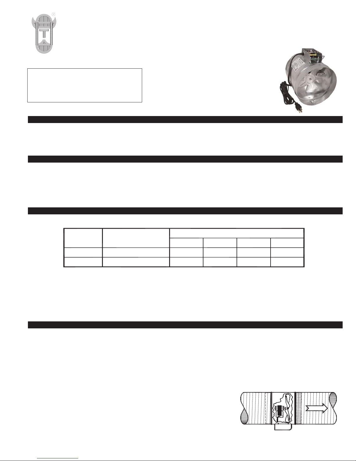
FLEXIBLE DUCT (Diagram A)
Choose a seam or other point in the duct where the EF-Series fan will be mounted.
IMPORTANT: For proper operation of the PRC control do not install the EF-AUTO
within 10 duct diameters from outlet end supply register. For example if the duct is 6”,
6 x 10 = 60” from outlet supply register. Cut or separate the flexible duct and install
the fan with fan blade facing the direction of air flow, (See Diagram A). Seal both
sides with duct tape and/or a flexible duct clamp. Support with plumber’s strap or
other suitable method if necessary.
TJERNLUND PRODUCTS, INC.
1601 Ninth Street • White Bear Lake, MN 55110-6794
PHONE (800) 255-4208 • (651) 426-2993 • FAX (651) 426-9547
Visit our web site • www.tjernlund.com
READ OWNER’S INSTRUCTIONS CAREFULLY PRIOR TO INSTALLATION.
THESE INSTRUCTIONS MUST REMAIN
WITH EQUIPMENT. DO NOT DESTROY.
AUTOMATIC
DUCT BOOSTER® MODELS
EF-6AUTO & EF-8AUTO
©2008 TJERNLUND PRODUCTS, INC. ALL RIGHTS RESERVED P/N: 8504157
EF-6 AUTO
120V 30 Watt 0.4A
150 CFM 100 CFM 90 CFM180 CFM
120VEF-8 AUTO 56 Watt
1.1A
300 CFM 250 CFM325 CFM 200 CFM
MOTOR
SPECIFICATIONS
MODEL
DUCT LENGTH AND AIR FLOW (Cubic Ft / Minute)
0 FEET 25 FEET 50 FEET 75 FEET
AIR FLOW
8050017 10/20/08
DIAGRAM A
Page 2
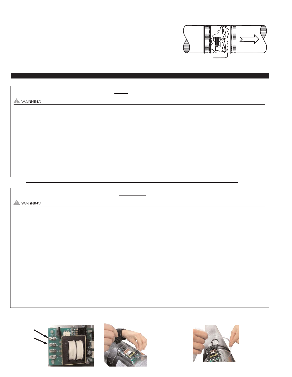
SHEET METAL DUCT (Diagram B)
Choose a joint on the existing duct where the EF-Series fan will be mounted.
IMPORTANT: For proper operation of the PRC control do not install the EF-AUTO
within 10 duct diameters from outlet end supply register. For example if the duct is 6”,
6 x 10 = 60” from outlet supply register. Separate the existing duct sections at the joint.
Cut a piece of duct on the female side of the existing duct 1 inch shorter than the
shroud length of the EF-Series model being installed. NOTE: DO NOT CUT OFF A
PIECE OF EXISTING DUCT WHICH HAS THE CRIMPED END. Insert fan in duct with
fan blade facing the direction of air flow, (See Diagram B). Seal joints with duct tape. If
extra support is necessary, use screws provided. Support with plumber’s strap or other
suitable method if necessary.
TROUBLESHOOTING
Motor (M2)
Motor (M1)
FOLLOW THE STEPS BELOW FOR A NEW INSTALLATION:
It may be necessary to measure voltage during troubleshooting. Extreme caution must be exercised to prevent injury.
If EF-AUTO fan does not run when the forced air handler fan/blower is running, verify 115 VAC power is supplied to the outlet the
EF-AUTO is plugged into. If 115 VAC power is supplied to outlet and EF-AUTO does not run follow the steps below.
Block register at end of EF-AUTO duct run and turn on air handler fan/blower. If EF-AUTO turns on with register blocked, verify fur-
nace filter is clean. Replace filter if dirty and see if EF-AUTO turns on when air handler fan/blower is running. If filter is clean, move
EF-AUTO closer to the Air handler fan/blower to see if higher pressure turns EF-AUTO on. Proceed to next step if EF-AUTO does not
turn on.
CAUTION: You will need to check for voltage across PRC control to proceed. Pull motor leads off of M1 & M2 on PRC sensing control. With forced air handler fan/blower running, check for 115 VAC across M1 & M2 on PRC sensing control, (See Diagram C). If voltage is not present, contact Tjernlund Products, Inc. @ 800-255-4208 for further assistance.
FOLLOW THE STEPS BELOW FOR AN EXISTING INSTALLATION:
It may be necessary to measure voltage during troubleshooting. Extreme caution must be exercised to prevent injury.
If EF-AUTO fan does not run when the forced air handler fan/blower is running, verify 115 VAC power is supplied to the outlet the
EF-AUTO is plugged into. If 115 VAC power is supplied to outlet and EF-AUTO does not run follow the steps below.
IMPORTANT: Unplug EF-AUTO fan from outlet before proceeding. Use a small screw driver to carefully pry sensing tube off of PRC
sensing port while at the same time pulling on sensing tube, (See Diagram D). Use compressed air or blow in sensing tube going to
sampling port in EF-AUTO housing, (See Diagram E). Replace tubing, plug in EF-AUTO, wait 30 seconds and turn air handler
fan/blower on to see if EF-AUTO turns on. Proceed to next step if EF-AUTO does not turn on.
Block register at end of EF-AUTO duct run and turn on air handler fan/blower. If EF-AUTO turns on with register blocked, verify furnace filter is clean. Replace filter if dirty and see if EF-AUTO turns on when air handler fan/blower is running. If filter is clean, move
EF-AUTO closer to the Air handler fan/blower to see if higher pressure turns EF-AUTO on. Proceed to next step if EF-AUTO does not
turn on.
CAUTION: You will need to check for voltage across PRC control to proceed. Pull motor leads off of M1 & M2 on PRC sensing control. With forced air handler fan/blower running, check for 115 VAC across M1 & M2 on PRC sensing control, (See Diagram C). If voltage is present apply 115 VAC to motor leads to see if motor is defective. If voltage is not present, replace PRC control board or contact Tjernlund Products, Inc. @ 800-255-4208 for further assistance.
AIR FLOW
8050018 10/20/08
DIAGRAM B
DIAGRAM EDIAGRAM D
DIAGRAM C
USE COMPRESSED
AIR OR BLOW IN SENSING TUBE GOING TO
SAMPLING PORT IN
EF-AUTO HOUSING.
MEASURE FOR 115
VAC ACROSS M1 &
M2 WHILE AIR HANDLER FAN/BLOWER
IS RUNNING.
USE A SMALL SCREW
DRIVER TO CAREFULLY PRY SENSING TUBE
OFF OF PRC SENSING
PORT WHILE AT THE
SAME TIME PULLING
ON SENSING TUBE.
Page 3

MAINTENANCE & SERVICE
If installed on a forced air heating or cooling system where filters are properly installed and maintained, no cleaning of the EF-AUTO
Series fan or motor should be required.
The EF-AUTO Series fans have high temperature lubrication and require no oiling.
TJERNLUND LIMITED ONE YEAR WARRANTY
Tjernlund Products, Inc. warrants to the original purchaser of this product that the product will be free from defects due to faulty material or workmanship for a period of (1)
year from the date of original purchase or delivery to the original purchaser, whichever is earlier. Remedies under this warranty are limited to repairing or replacing, at our
option, any product which shall, within the above stated warranty period, be returned to Tjernlund Products, Inc. at the address listed below, postage prepaid. THERE ARE
NO WARRANTIES WHICH EXTEND BEYOND THE DESCRIPTION ON THE FACE HEREOF, AND TJERNLUND PRODUCTS, INC. EXPRESSLY DISCLAIMS LIABILITY
FOR INCIDENTAL OR CONSEQUENTIAL DAMAGES ARISING FROM THE USE OF THIS PRODUCT. THIS WARRANTY IS IN LIEU OF ALL OTHER EXPRESS WARRANTIES AND NO AGENT IS AUTHORIZED TO ASSUME FOR US ANY LIABILITY ADDITIONAL TO THOSE SET FORTH IN THIS LIMITED WARRANTY. IMPLIED
WARRANTIES ARE LIMITED TO THE STATED DURATION OF THIS LIMITED WARRANTY. Some states do not allow limitation on how long an implied warranty lasts, so
that limitation may not apply to you. In addition, some states do not allow the exclusion or limitation of incidental or consequential damages, so that above limitation or
exclusion may not apply to you. This warranty gives you specific legal rights and you may also have other rights which may vary from State to State. Send all inquiries
regarding warranty work to Tjernlund Products, Inc. 1601 9th Street, White Bear Lake, MN 55110-6794. Phone (651) 426-2993 • (800) 255-4208 • Fax (651) 426-9547 •
Email fanmail@tjfans.com.
PRESSURE RESPONSE CONTROL (FACTORY WIRING)
Ground Wire
Power Cord
Ribbed (L2)
Power Cord
Non-Ribbed (L1)
Motor (M2)
Motor (M1)
REPLACEMENT PARTS AND WARRANTY
Description Part Number
EF-6AUTO Motor 950-0416
EF-6AUTO Blade 950-0417
EF-8AUTO Motor 950-0428
EF-8AUTO Blade 950-0418
EF-AUTO Pressure Response Control Kit 950-9150
WHAT IS NOT COVERED
Product installed contrary to our installation instructions.
Any freight charges related to the return of the defective part.
Product that has been altered, neglected or misused.
Any labor charges related to evaluating and replacing the defective part.
 Loading...