


BACK COVER |
TIPPMANN |
LINE |
® |
TM MARKER |
|
|
• Owner’s Manual |
|
|
• Le Manuel du Propriétaire |
|
|
• Manual del Usuario |
|
TM
BASIC
TP04110
Date: 12/06

|
|
|
|
E |
|
|
WARNING |
|
THIS IS NOT A TOY. MISUSE MAY CAUSE SERIOUS |
||
N |
|
INJURY OR DEATH. EYE, FACE AND EAR PROTECTION |
|
G |
|
DESIGNED FOR PAINTBALL MUST BE WORN BY THE |
|
L |
|
|
USER AND ANY PERSON WITHIN RANGE. WE |
|
RECOMMEND AT LEAST 18 YEARS OLD TO PURCHASE. |
||
I |
|
PERSONS UNDER 18 MUST HAVE ADULT SUPERVISION |
|
S |
|
WHEN USING THIS PRODUCT. READ THE OWNER’S |
|
H |
|
MANUAL BEFORE USING THIS PRODUCT. |
|
|
|
|
|
|
|
|
|
F |
AVERTISSEMENT |
CE N’EST PAS UN JOUET. L’USAGE IMPROPRE PEUT |
|
R |
CAUSER LA BLESSURE SÉ RIEUSE OU LA MORT. LA |
A |
PROTECTION POUR LES YEUX, LE VISAGE ET LES |
N |
OREILLES CONSTRUITE POUR LA BALLE DE PEINT |
DOIT Ê TRE PORTÉ E PAR L’UTILISATEUR ET N’IMPORTE |
ÇQUELLE PERSONNE DANS LE CHAMP DE TIR. NOUS
A RECOMMENDONS QU’ ON A DIX – HUIT ANS AU MOINS |
||
I |
POUR L’ACHETER. LES PERSONNES SOUS L’Â GE DE |
|
DIX – HUIT ANS DOIVENT AVOIR LA SUPERVISION D’ |
||
|
||
SUN ADULTE QUAND ON EMPLOIE CE PRODUIT. IL FAUT LIRE TOUT DE CE MANUEL AVANT DE L’UTILISER.
|
|
|
E |
|
ADVERTENCIA |
|
ESTO NO ES UN JUGUETE. UN USO INAPROPIADO |
|
S |
|
PUEDE CAUSAR SERIAS HERIDAS O LA MUERTE. |
P |
|
OJOS, CARA Y OIDOS DEBEN SER PROTEGIDOS TODO |
A |
|
EL TIEMPO, CON LA PROTECCIÓ N DISEÑ ADA PARA |
|
PAINTBALL TANTO POR JUGADORES COMO POR |
|
Ñ |
|
CUALQUIER PERSONA QUE ESTE EN EL RADIO DE |
O |
|
ALCANCE. RECOMENDAMOS AL MENOS 18 AÑ OS |
L |
|
PARA LA COMPRA Y USO. LAS PERSONAS MENORES |
|
DE 18 AÑ OS DEBEN USAR ESTE PRODUCTO BAJO LA |
|
|
|
|
|
|
SUPERVISIÓ N DE UN ADULTO. ANTES DE USAR ESTE |
|
|
PRODUCTO LEA EL MANUAL DEL USUARIO. |
|
|
|
|
|
|
|
|
|
|
|
|
WARNING |
|
|
|
E |
|
SAFETY IS YOUR RESPONSIBILITY |
|
BARREL SLEEVE |
|
||
READ, FAMILIARIZE |
|
|
|
|
N |
YOURSELF AND ANY |
|
|
|
|
G |
OTHER USER OF THIS |
|
|
|
|
|
MARKER WITH THE |
|
|
ALWAYS KEEP |
|
L |
ALWAYS KEEP |
|
|
|||
SAFETY INSTRUCTIONS |
|
BARREL SLEEVE |
|
I |
|
IN THIS MANUAL. |
TRIGGER SAFETY IN |
INSTALLED WHEN |
|
||
FOLLOW THESE |
SAFE MODE = |
|
NOT IN SHOOTING |
|
S |
INSTRUCTIONS WHEN |
UNLESS FIRING |
|
SITUATION AS |
|
|
USING, WORKING ON, |
AS DETAILED IN |
|
DETAILED IN |
|
H |
TRANSPORTING OR |
INSTRUCTIONS |
|
INSTRUCTIONS ON |
|
|
STORING THIS MARKER. |
ON PAGE 4. |
|
PAGE 2. |
|
|
|
|
|
|
|
|
AVERTISSEMENT |
|
F |
|||
SÉ CURITÉ EST VOTRE RESPONSABILITÉ |
|
LA CHEMISE DU CANON |
|
||
IL FAUT LIRE, VOUS |
|
|
|
|
R |
FAMILIARISER ET TOUS |
|
|
|
|
|
LES AUTRES UTILISATEURS |
|
|
|
|
A |
DE CE MARQUEUR |
|
|
|
|
N |
AVEC LES INSTRUCTIONS |
IL FAUT TOUJOURS |
|
IL FAUT TOUJOURS |
|
|
DE SÉ CURITÉ DANS CE |
GARDER LA DÉ TENTE |
GARDER LA |
|
Ç |
|
MANUEL. SUIVEZ CES |
DANS UNE MODE DE |
CHEMISE DU CANON |
|
||
INSTRUCTIONS QUAND |
SÉ CURITÉ = |
|
INSTALLÉ E QUAND |
|
A |
VOUS UTILISEZ, |
SAUF QUAND ON TIRE |
ON NE TIRE PAS |
|
I |
|
TRAVAILLEZ SUR, |
COMME DÉ TAILLÉ S |
|
COMME DÉ TAILLÉ S |
|
|
TRANSPORTEZ, OU |
DANS LES |
|
DANS LES |
|
S |
ENTREPOSEZ CE |
INSTRUCTIONS À LA |
INSTRUCTIONS À LA |
|
|
|
MARQUEUR. |
PAGE 3 |
|
PAGE 1. |
|
|
|
|
|
|
|
|
ADVERTENCIA |
|
E |
|||
LA SEGURIDAD ES SU RESPONSABILIDAD |
|
FUNDA DE SEGURIDAD |
|
||
EL PROPIETARIO Y TODA |
|
|
|
|
S |
PERSONA QUE VA A USAR |
|
|
|
|
P |
ESTE MARCADOR DEBE |
|
|
|
|
|
LEER Y FAMILIARIZARCE |
|
|
|
|
A |
MANTENGA SIEMPRE EL MANTENGA LA |
|
||||
CON LAS INSTRUCCIONES |
|
||||
SEGURO DEL GATILLO |
FUNDA DE |
|
Ñ |
||
DE SEGURIDAD EN ESTE |
|
||||
ACTIVADO = |
A |
SEGURIDAD |
|
||
MANUAL. SIGA LAS |
|
O |
|||
MENOS QUE SEA |
|
INSTALADA |
|
||
INSTRUCCIONES DE USO, |
|
|
|||
MANTENIMIENTO, |
NECESARIO HACER |
CUANDO NO ESTE |
|
L |
|
DISPAROS. INMEDIATOS |
HACIENDO DISPAROS |
|
|||
TRANSPORTE Y |
|
||||
COMO SE VE EN LAS |
|
COMO SE ILUSTRA |
|
|
|
ALMACENAJE DE ESTE |
|
|
|
||
INSTRUCCIONES |
|
EN LA PÁ GINA 1. |
|
|
|
MARCADOR. |
|
|
|
||
DE LA PÁ GINA 3. |
|
|
|
|
|
|
|
|
|
|
|
|
|
|
|
|
|
|
|
|
|
|
|

E |
|
WARNING |
|
THIS IS NOT A TOY. MISUSE MAY CAUSE SERIOUS INJURY OR |
|
N |
|
DEATH. EYE, FACE AND EAR PROTECTION DESIGNED FOR |
G |
|
PAINTBALL MUST BE WORN BY THE USER AND ANY PERSON |
|
WITHIN RANGE. WE RECOMMEND AT LEAST 18 YEARS OLD |
|
L |
|
TO PURCHASE. PERSONS UNDER 18 MUST HAVE ADULT |
|
SUPERVISION WHEN USING THIS PRODUCT. READ THE |
|
I |
|
|
|
OWNER’S MANUAL BEFORE USING THIS PRODUCT. |
|
S |
|
|
|
|
|
|
WARNING |
|
H |
|
|
|
|
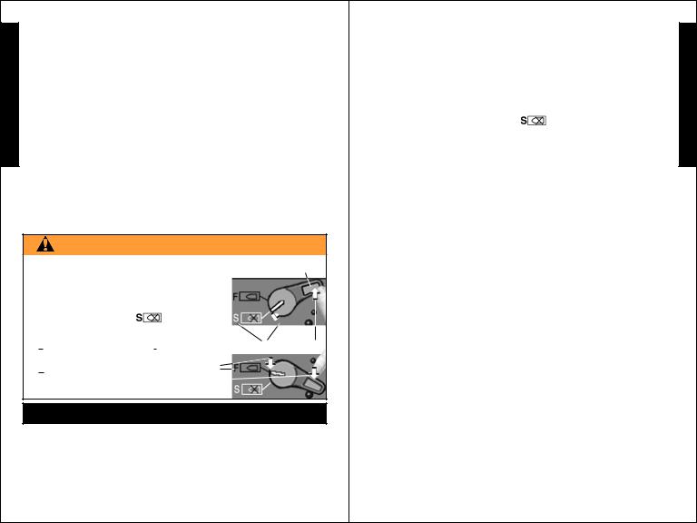
BARREL SLEEVE INSTALLATION |
|
|
• EXCEPT WHEN YOUR MARKER IS IN USE, ALWAYS MAKE |
|
|
SURE THAT THE TRIGGER SAFETY IS IN SAFE MODE = |
|
|
(SEE INSTRUCTIONS ON PAGE 4), AND THE BARREL SLEEVE |
|
|
IS PROPERLY INSTALLED ON YOUR MARKER AS FOLLOWS. |
|
|
1) SLIDE BARREL INTO SLEEVE AND LOOP CORD OVER TOP |
|
|
OF RECEIVER AND POSITION AT BACK OF GRIP AS SHOWN. |
|
|
CORD |
|
|
LENGTH |
|
|
ADJUSTOR |
|
|
BUTTON |
2)PINCH CORD LENGTH ADJUSTOR BUTTON AND
HOLD TO BACK OF GRIP
AS YOU PULL CORD THROUGH IT UNTIL ADJUSTOR IS SNUG AGAINST BACK OF GRIP, THEN RELEASE BUTTON.
3)CHECK TO BE SURE THERE IS ENOUGH CORD ELASTICITY TO PULL CORD/ADJUSTOR OFF OF GRIP TO REMOVE BARREL SLEEVE FOR FIRING.
4)AFTER CORD LENGTH
IS ADJUSTED, LOCK
CORD LENGTH BY TYING
A KNOT IN THE CORD
AGAINST THE BACK OF
THE ADJUSTOR AS SHOWN.
2
TIPPMANN® |
|
|
|
|
|
E |
|
2955 Adams Center Road, Fort Wayne, IN 46803 USA |
|
N |
|
P) 260-749-6022 • F) 260-749-6619 |
|
|
|
www.tippmann.com |
|
|
G |
CONGRATULATIONS on your purchase of your Tippmann® |
L |
||
paintball marker. We believe our X7TM line of markers to be the |
|||
most accurate and durable paintball markers available, and |
I |
||
proudly manufactured in the USA. All Tippmann® X7TM models |
S |
||
will give many years of dependable service if cared for properly. |
H |
||
Please take time to read this manual thoroughly and become |
|
||
familiar with your Tippmann® X7TM markers’ parts, operation, and |
|
||
|
|||
safety precautions before you attempt to load or fire this marker. |
|
||
If you have a missing or broken part or need assistance, please |
|
||
contact Tippmann® Consumer Relations at 1-800-533-4831 for |
|
||
fast friendly service. |
|
|
|
TABLE OF CONTENTS |
|
2 |
|
Warning/Caution ............................................................................... |
|
|
|
Warning/Caution Barrel Sleeve Installation ................................... |
|
2 |
|
Warning/Liability Statement ............................................................ |
|
4 |
|
Safety is your Responsibility / Familiarize Yourself With Safety . 4 |
|
||
Safe Mode = Turning The Safety On (SAFE = white |
) |
....... 4 |
|
Fire Mode = Turning The Safety Off (FIRE = red |
) ............. |
4 |
|
Getting Started ................................................................................. |
|
6 |
|
1. Prepare Marker for Air Supply Cylinder Installation ............. |
6 |
|
|
2. Air Supply Cylinder Installation .............................................. |
|
6 |
|
3. Hopper and CycloneTM Feeder ................................................ |
|
6 |
|
4. Velocity Adjustment ................................................................. |
|
7 |
|
5. Rear Sight Adjustment ............................................................ |
|
7 |
|
Schematic: X7TM Basic Parts List .................................................... |
|
8 |
|
Unloading Your Marker .................................................................. |
|
10 |
|
Air Supply Cylinder Removal ........................................................ |
|
10 |
|
Cleaning & Maintenance ............................................................... |
|
10 |
|
Marker / Receiver Disassembly & Assembly ............................... |
|
11 |
|
Repairing Air Supply Leaks ........................................................... |
|
17 |
|
Storage ............................................................................................ |
|
17 |
|
Marker Model Specifications ......................................................... |
|
17 |
|
Warranty and Repair Policy .......................................................... |
|
18 |
|
Warranty or Repair Procedure ...................................................... |
|
18 |
|
Warranty Registration .................................................................... |
|
18 |
|
3 |
|
|
|
|
|
|
|
|
Warning / Liability Statement |
|
This marker is classified as a dangerous weapon and is surrendered |
E by Tippmann Sports, LLC with the understanding that the purchaser |
|
N assumes all liability resulting from unsafe handling or any action |
|
|
that constitutes a violation of any applicable laws or regulations. |
G Tippmann Sports, LLC shall not be liable for personal injury, loss of |
|
L |
property or life resulting from the use of this weapon under any |
I |
circumstances, including the intentional, reckless, negligent or |
accidental discharges. |
|
S |
All information contained in this manual is subject to change without |
Hnotice. Tippmann Sports, LLC reserves the right to make changes and improvements to products without incurring any obligation to incorporate such improvements in products previously sold.
If you as a user do not accept liability, Tippmann Sports, LLC requests you do not use a Tippmann Sports, LLC marker. By using this paintball marker you release Tippmann Sports, LLC of any and all liability associated with its use.
SAFETY IS YOUR RESPONSIBILITY!
WARNING
TRIGGER SAFETY ACTIVATION |
SAFETY |
|||
• EXCEPT WHEN YOUR MARKER IS IN USE, |
||||
|
||||
ALWAYS MAKE SURE THAT THE BARREL |
|
|||
SLEEVE IS INSTALLED (SEE PAGE 2) AND |
|
|||
THE TRIGGER SAFETY LEVER IS IN THE |
|
|||
SAFE MODE = WHITE |
|
|
|
|
|
|
|||
WHICH DISABLES THE TRIGGER. |
|
|||
TO TURN ON THE SAFETY (SAFE MODE = WHITE  ): PUSH THE SAFETY UP AS SHOWN ABOVE.
TO TURN THE SAFETY OFF (FIRE MODE
= RED  ): PUSH THE SAFETY DOWN.
FAMILIARIZE YOURSELF WITH SAFETY...
The ownership of this weapon places upon you the total responsibility for its safe and lawful use. You must observe the same safety precautions as you would any firearm to assure the safety of not only yourself but everyone around you. The user should at all times use caution when using this marker. The sport of Paintball will be viewed and judged upon your safe and sportsmanlike conduct. Always remember that the game of Paintball
4 |
Safety Is Your Responsibility |
|
(continued on page 5) |
Safety Is Your Responsibility (continued from page 4) |
|
|
can only survive and grow if it remains SAFE! |
|
|
• Do not load or fire this marker until you have completely read this |
E |
|
manual and are familiar with its safety features, mechanical |
||
operation and handling characteristics. |
N |
|
• Handle this and any marker as if it were loaded at all times. |
G |
|
• Keep your finger off the trigger until ready to shoot. |
||
• Do not look down the barrel of a paintball marker. Accidental |
L |
|
discharge into the eyes may cause permanent injury or death. |
I |
|
• Keep the marker on “SAFE”= |
until ready to shoot (see |
S |
page 4). |
|
|
• Keep the barrel sleeve installed on marker when not shooting |
H |
|
(see page 2). |
|
|
•Never point the marker at anything you do not intend to shoot.
•Never fire your marker at anything you do not intend to shoot because there may be balls or foreign debris lodged in the chamber, barrel and / or the marker valve.
•Do not shoot at fragile objects such as windows.
•Never fire your marker at personal property of others, the paintball can stain the paint of automobiles and houses.
•Always keep the muzzle pointed down or in a safe direction, even if you stumble or fall.
•Eye, face and ear protection designed specifically to stop paintballs in the form of goggles and full face mask meeting ASTM Specification F 1776 must be worn by the user and any person within range.
•Never shoot at a person who is not protected by eye, face and ear protection designed for paintball.
•Pressurize and load the marker only when the marker will be immediately used.
•NOTE: Before storing or disassembling be sure to remove paintballs and air supply (see unloading and air supply removal on page 10). Install the barrel sleeve (see page 2).
•Store the marker unloaded and degassed in a secure place.
•Do not field strip or otherwise disassemble this marker while it is pressurized with air supply.
•Dress appropriately when playing the game of paintball. Avoid exposing any skin when playing the game of paintball. Even a light layer will absorb some of the impact and protect you from the paintballs.
•Keep exposed skin away from escaping gas when installing or removing air supply cylinder or if the marker or air supply is leaking. Compressed air, CO2, and nitrogen gasses are
5 |
Safety Is Your Responsibility |
|
(continued on page 6) |

Safety Is Your Responsibility (continued from page 5)
|
very cold and can cause frostbite under certain conditions. |
|
• Use only .68 caliber paintballs, never load or fire any foreign objects. |
E • Avoid alcoholic beverages before and during the use of this |
|
N |
marker. Handling markers while under the influence of drugs |
G |
or alcohol is a criminal disregard for public safety. |
• Avoid shooting an opponent at point blank, 6 feet or less. |
|
L • Familiarize yourself with instructions listed on air supply cylinder |
|
I |
or adaptor. Contact the air supply cylinder or adaptor manufacturer |
S |
with any questions. |
• Always measure your marker’s velocity before playingpaintball |
|
Hand never shoot at velocities in excess of 300 feet per second (see instructions on page 7).
GETTING STARTED:
Eye protection designed for paintball use must be worn by the user and any person within range.
STEP 1: Prepare Marker for Air Supply Cylinder Installation
Before installing the air supply, install the Barrel and Front Grip as outlined on page 15 (do not install the hopper until STEP 3:).
STEP 2: Air Supply Cylinder Installation
• Do not pressurize a partially assembled paintball marker.
1)Install barrel sleeve (see instructions on page 2).
2)Put the trigger safety in Safe Mode =  (see page 4 instructions).
3)Cock the marker by sliding the bolt handle all the way back until you hear / feel it click into place. Then release cocking handle. Cocking handle will slide forward. Marker is now cocked. Always keep marker in the cocked position when air supply is attached to marker. This will help prevent an accidental discharge.
4)To install the air supply cylinder, lubricate the cylinder valve o-ring with a little Tippmann® paintball marker oil then insert the cylinder valve end into the air supply adapter at the back end of the marker grip. Twist the cylinder clockwise into the adapter until it stops. Your marker is ready to fire once you switch to the Fire
Mode =  from the Safe Mode =
  . If the tank is full and you do not hear the air supply engage, the pin valve could be too short or the pin valve seal is damaged.
STEP 3: Hopper and CycloneTM Feeder
1) Barrel Sleeve must be installed (see page 2) and safety in
6 |
Getting Started |
|
(continued on page 7) |
||
|
Getting Started (continued from page 6)
Safe Mode= |
(see page 4) before filling the hopper. |
|
|
|
|
|
|||
2) Make sure that the CycloneTM feeder housing is clean, free of |
E |
|||
debris, and the CycloneTM feeders turn freely when the manual |
||||
advance lever knob is pushed. |
|
|
N |
|
3) Make sure that the hopper is clean, free of sharp edges or |
G |
|||
debris. This will keep the paintballs from breaking and feed the |
L |
|||
marker smoothly. |
|
|
|
|
4) Install the hopper neck into the CycloneTM feeder housing |
I |
|||
aligning the hopper neck tab to fit into the cutout in the CycloneTM |
S |
|||
feeder housing and turn counterclockwise |
to secure. |
With |
H |
|
the barrel sleeve installed and safety in Safe Mode = |
, you |
|||
are now ready to load your hopper with paintballs. After filling |
|
|||
the hopper with paintballs the chamber will still be empty. You |
|
|||
need to push the feeder manual advance lever to chamber a |
|
|||
paintball. Only remove barrel sleeve and turn off the safety |
|
|||
when ready to shoot. |
|
|
|
|
STEP 4: Velocity Adjustment |
|
Each time you play paintball, the |
Allen Wrench |
velocity of your paintball marker |
|
should be checked with a |
Velocity |
chronograph, an instrument for |
Adjustment |
measuring velocity, prior to playing |
Screw |
|
|
paintball to verify that the marker’s |
|
velocity is set below 300 feet per |
|
second or less if required by the |
Feeder Manual |
playing field. |
Advance Lever |
To adjust the velocity: use the ( 3/16” ) allen wrench included with your marker. The velocity adjustment screw is located on the right side of the receiver. To adjust the velocity down, turn the screw inward or clockwise  . To turn the velocity up, turn the screw out or counterclockwise
  . Do not remove velocity screw. NOTE: You must turn the velocity screw all the way in before doing any disassembly.
STEP 5) Rear Sight Adjustment
Rear Sight If your marker fires to low: Rotate the  Adjuster rear sight adjuster counterclockwise
  to
to
raise the impact point.
If your marker fires to high: Rotate the rear sight adjuster clockwise  to lower the impact point.
7

TIPPMANN |
BASIC PARTS LIST |
® |
E
N
G
L
I
S
H
8
WARNING
DO NOT DISASSEMBLE THIS MARKER WHILE IT IS PRESSURIZED E WITH AIR. DO NOT PRESSURIZE A PARTIALLY ASSEMBLED MARKER. N
G
L
I
S
H
9

Unloading Your Marker
EEye protection designed for paintball use must be worn by the user and any person within range.
N To unload your marker:
G1) Install the barrel sleeve (see page 2). 2) Empty and remove the hopper.
L 3) Go to a designated firing area and remove the barrel sleeve. I 4) Point your marker in a safe direction and fire several times to S be sure there are no balls lodged in the chamber and / or barrel.
IMPORTANT: Do not uncock your marker as uncocking your marker H may push a ball into the chamber or down into the barrel in which
case the ball will be hidden from view. 5) Install the barrel sleeve (see page 2).
6) Visually inspect the CycloneTM Feeder and chamber for paintballs.
Air Supply Cylinder Removal
Eye protection designed for paintball use must be worn by the user and any person within range.
To remove a charged air supply cylinder:
1)Install the barrel sleeve (see page 2).
2)Turn the cylinder approximately 3/4 of a turn counterclockwise
 or out. This allows the air supply pin valve to close so that no air will enter the marker.
3) Point the marker in a safe direction and fire the remaining gas in the marker by pulling the trigger until the marker stops firing. This may take 4-5 shots.
•If your marker keeps firing after you have turned the tank 3/4 of a turn, the tank pin valve has not closed yet and you may have to turn the tank counterclockwise a little further.
•If you turn the tank 3/4 of a turn and it begins to leak before you pull the trigger you have turned it too far and may have damaged the tank o-ring.
•Because of the variances in tank valve parts, each tank varies slightly on exactly how far it should be turned. If this process does not work the tank pin valve could be too long.
NOTE: Before storing or disassembling be sure to follow Unloading Your Marker and Air Supply Cylinder Removal instructions (see above). Install barrel sleeve (see page 2).
Cleaning & Maintenance
Eye protection designed for paintball use must be worn by the user and any person within range.
To reduce the chance of accidental discharge: First follow Unloading
10 |
Cleaning and Maintenance |
|
(continued on page 11) |
Cleaning and Maintenance (continued from page 10)
Your Marker and Air Supply Cylinder Removal instructions (see above) and never disassemble a marker that is under pressure.
•Follow warnings listed on the air supply cylinder for handling and storage.
•Familiarize yourself with instructions listed on air supply cylinder or adaptor. Contact the air supply cylinder or the adaptor manufacturer with any questions.
•Do not use any petroleum based cleaning solvents.
•Do not use any cleaning solvents that come in aerosol cans. NOTE: Petroleum based products and aerosol products can damage your markers’ o-rings.
•To clean your paintball marker: use a damp towel with water to wipe off paint, oil, and debris. Use Tippmann® paintball marker oil or other premium paintball marker oil to lubricate and maintain your marker in good working condition.
Inspect and lubricate the internal drive assembly parts: the front bolt o-ring, the rear bolt o-ring, the linkage arm and the drive spring / guide pin (see Drive Assembly Removal and Installation instructions on page 13).
Inspect and lubricate the barrel o-ring and the air supply valve o-ring with a few drops of oil.
•To clean inside the barrel: remove barrel and insert metal tab of cable squeegee into barrel, then pull squeegee through barrel to remove debris.
Marker / Receiver Disassembly & Assembly
Eye protection designed for paintball use must be worn by the user and any person within range.
1)First follow Unloading Your Marker and Air Supply Cylinder Removal instructions on page 10. Remove air supply before any disassembly. Do not pressurize a partially assembled paintball marker.
2)Put the marker in the uncocked position. To uncock the marker: hold the bolt cocking handle  back 3/4 - then pull the trigger and release handle forward which will uncock the marker.
3)To remove the hopper  :
:
turn the hopper clockwise and lift out.
4)To remove the Front Grip  : Remove short push pin
  / and long push pin
  and slide the front grip off.
5)To remove the Barrel  :
:
Twist the barrel counterclockwise |
to remove. |
11 |
Receiver Disassembly / Assembly |
|
(continued on page 12) |
E N G L I S H

Receiver Disassembly / Assembly (continued from page 11)
|
TOOLS: The magazine contains Tools and lubricating oil for your marker. |
||||||||
|
6) To remove the magazine |
|
from the magazine base |
press the |
|||||
E magazine button |
(on right side of the magazine base, then slide |
||||||||
N magazine down and out. Store |
|
|
|
|
|
|
|||
|
|
|
|
|
|
||||
|
tools in magazine after use (shown |
|
|
|
|
||||
G with 2 allen wrenches and oil. |
|
|
|
|
|
|
|
||
|
|
|
|
|
|
|
|||
L |
7) To remove the Front Sight |
|
: |
|
|
|
|
||
I |
Remove Front Sight Screw |
|
|
|
|
|
|
||
S |
and slide the front sight off . |
|
|
|
|
|
|
||
8) To remove the Rear Sight |
|
: |
|
|
|
|
|||
H Remove 2 rear sight screws |
/ |
|
and the Rear Sight |
. |
|
||||
Receiver Disassembly
Eye protection designed for paintball use must be worn by the user and any person within range.
FIRST: perform steps 1), 2), 3), 4), 5), 6), 7) and 8) as outlined on pages 11 and 12 before beginning Receiver Disassembly.
•To remove the lower receiver (grip)  : Remove the 2 long lower receiver push pins
  /
/  and pull the lower receiver
  from the upper receiver
  .
.
•To remove the gas line  / Tombstone from the upper receiver:
Remove the lower receiver  see above. Remove the long push pin
  from the upper receiver. Remove the magazine
  from the magazine base
  by pressing the magazine button
  (on right side of magazine base), then slide magazine down and out. Slide magazine base
  back until it stops, then down. Pull down on gas
12 |
Receiver Disassembly / Assembly |
|
(continued on page 13) |
Receiver Disassembly / Assembly (continued from page 12)
line  to remove the gas line/Tombstone. NOTE: If you remove the gasline from the Tombstone, when reinstalling, inspect and oil the o-ring and be careful not to overtighten and strip threaded parts.
•To remove trigger assembly  from the lower receiver
  (grip):Rotate the Safety Selector Switch
  straight up
and pull it out left side of lower receiver. Pull up on the trigger assembly  keeping it intact.
•To access trigger parts: Pull left plate off trigger
assembly  . Do not remove the 5 dowel pins from the right plate. See trigger assembly on page 9.
Drive Assembly Removal and Installation
NOTE: It is not necessary to disassemble the upper receiver to access and service the drive assembly internal parts.
To remove the drive assembly parts: front bolt, power tube, valve, rear bolt/rear bolt plug, linkage arm, drive pin guide, drive spring and end cap (parts shown on pages 8 and 9).
1)Remove air supply before any disassembly: Unload marker, remove the air supply as outlined on page 10 and put the marker in the uncocked position before beginning to disassemble it. To uncock the marker, hold
the bolt cocking handle back 3/4 - then pull the trigger and release handle forward  which will uncock the marker.
2)Remove gas line  and lower receiver (grip)
  see Receiver Disassembly instructions on page 12.
3)Screw velocity screw  in past receiver.
4)Remove last push pin (short)  holding end cap in place.
5)Pull end cap  out and tilt marker up, drive assembly parts should slide out the back. You may need to jiggle marker while sliding parts out.
To reinstall drive assembly parts and lower receiver:
1)Clean inside upper receiver and removed parts.
2)Inspect and replace any damaged parts. Lubricate the front bolt o-ring, the rear bolt o-ring, the linkage arm and the drive spring/ guide pin with a few drops of Tippmann® paintball marker oil (or other premium paintball marker oil) before reinstalling them.
3)Insert valve into power tube with Tombstone cutout aligned down to match power tube cutout. (Insert tombstone adapter to check fit).
4)Insert reassembled parts - front bolt, power tube/valve, rear bolt/rear
bolt plug, with linkage arm facing up, until tombstone adapter can be
inserted, long push pin  replaced and velocity screw
  can be accessed. You may need to jiggle marker while sliding parts in.
5)Insert the guide pin into the drive spring and drive spring into the rear bolt plug. Insert the end cap, while keeping the guide pin centered
in it. Install the upper end cap short push pin |
. |
13 |
Receiver Disassembly / Assembly |
(continued on page 14) |
E N G L I S H

|
|
Receiver Disassembly / Assembly (continued from page 13) |
|
|
|
Lower Receiver Disassembly/Assembly: |
|
|
|||
E |
|
• To disassemble the lower receiver: |
|
|
1) Follow the Marker / Receiver Disassembly instructions on pages |
||
N |
|
11, 12 and 13 until you have detached the lower receiver and |
|
G |
|
removed the trigger assembly |
from the grip. |
L |
|
2) Remove the tank adapter bolt . |
|
|
3) Remove the 3 grip screws |
holding the two lower |
|
I |
|
receiver grip halves together. |
|
S |
|
|
|
|
|
|
|
H |
|
|
|
|
|
|
|
|
|
|
|
•To reassemble the lower receiver (grip):
1)Make sure the trigger guard is in place.
2)Replace left grip half  .
.
3)Secure the grip halves with 3 grip screws  .
.
4)Attach Tank Adapter: Slide tank adapter into the
lower receiver and align holes; |
Insert receiver bolt |
|
and tighten. |
|
|
5) Insert trigger group |
into the grip. Rotate the |
|
Safety Selector Switch |
straight up and insert it into |
|
the left side of the grip and then rotate it to the “SAFE”=  position.
•To attach the lower receiver (grip) to the upper receiver.Line up lower receiver front push pin holes with upper receiver holes then gently rock rear of grip until you can
insert the two long lower receiver push pins  &
&  to attach.
14 |
Receiver Disassembly/Assembly: |
|
(continued on page 15) |
Receiver Disassembly / Assembly (continued from page 14)
Barrel and Front Grip:
• |
To install Barrel: Insert barrel and turn clockwise . |
|
E |
|
• |
To install Front Grip: Slide front grip onto barrel/upper receiver |
|||
|
and insert short push pin |
in top and long push pin |
in |
N |
|
bottom to attach. |
|
|
G |
CycloneTM Feed System Removal |
|
L |
||
FIRST: Remove air supply before any disassembly: Unload |
I |
|||
marker, remove the air supply as outlined on page 10 and put |
S |
|||
the marker in the uncocked position before beginning to disassemble |
H |
|||
it. To uncock the marker, hold the bolt cocking handle back 3/4 - |
||||
then pull the trigger and release handle forward which will uncock |
|
|||
the marker. |
|
|
|
|
|
|
|
||
Remove banjo fitting bolt  from upper receiver. Remove CycloneTM housing bolt
  from left front side of upper receiver and remove feed system
  . To install reverse the process.
Upper Receiver Disassembly:
NOTE: It is only necessary to disassemble upper receiver halves to access the ball latch, cocking handle, cocking handle spring and (receiver o-ring - the receiver o-ring  is glued in place, only remove it if it is damaged. To replace the receiver o-ring: 1) pull it out; 2) clean receiver groove of glue; 3) place 4 equally spaced drops of CA glue (cyanoacrylate - super glues) into bottom of groove and press new o-ring into place. 4) Allow the glue to dry before reassembling.)
To disassemble the Upper Receiver:
1)Follow Marker / Receiver Disassembly instructions on pages 11 and 12 until you have removed the gas line/Tombstone from the upper receiver.
2)Remove the 4 short Receiver Bolts  /
/ /
/ /
/ and the 3 long Receiver Bolts
  /
/ /
/ holding the 2 upper receiver halves together and lift the left half off of the right
receiver half. NOTE: long receiver bolt  is not visible until the lower receiver (grip) has been removed.
15 |
Upper Receiver Disassembly/Assembly: |
|
(continued on page 16) |

Upper Receiver Disassembly / Assembly (continued from page 15)
|
Upper Receiver Assembly: |
|
|
|
||||||
E |
1) Make sure all parts are cleaned and oiled before reassembling. |
|||||||||
Place right upper receiver half flat with (Ball Latch |
inserted) |
|||||||||
N |
and (receiver o-ring |
glued) in position as shown below. |
||||||||
G |
2) With left hand, grip left |
3) With left hand holding as |
||||||||
L |
upper receiver half as shown |
shown below, use right hand to seat |
||||||||
I |
to hold Cocking Handle |
|
cocking handle with spring into |
|||||||
and spring |
in |
place |
by |
receiver cutout |
|
then position |
||||
S |
applying side pressure with |
edge of spring in end of spring |
||||||||
H |
index finger |
pushing |
in |
cutout |
bowed as shown below |
|||||
direction of arrows |
against |
. Then grip left receiver with |
||||||||
|
Cocking Handle. |
|
|
|
right hand as shown. |
|||||
|
Right |
|
Cocking Handle Spring |
|
Cocking Handle |
|||||
|
|
|
will be bowed. |
|
|
Left |
||||
|
Hand |
|
|
|
|
|
|
|||
|
|
|
|
|
|
|
|
|
|
Hand |
|
Left |
|
|
|
|
|
|
|
||
|
Half |
|
|
|
|
|
|
|
|
Ball |
|
|
|
|
|
|
|
|
|||
|
Right |
|
|
|
|
|
|
|||
|
Half |
|
|
|
|
|
|
Latch |
||
4)Use your finger tips to guide the left half straight down on to right half until receiver halves fit flush. If it does not fit flush the first time, check to make sure the spring and other parts have stayed in place and repeat until halves fit flush.
5)Oil the Barrel/adapter o-rings. Follow the illustration and Insert 4 short bolts  /
/ /
/ /
/ and 3 long bolts
  /
/ /
/ into correct spots and tighten them just enough to hold halves flush yet loose
enough to allow you to now insert and twist Barrel / Adapter unit clockwise  to reinstall. 6) Carefully tighten all 7 bolts (do not overtighten and strip threaded parts).
16
Repairing Air Supply Cylinder Leaks |
|
|
|
The most common leak occurs from a bad air supply valve o-ring. |
E |
||
To replace a valve o-ring you must first remove the bad o-ring and |
|||
then install a new one. This o-ring is located on the tip of your air |
N |
||
supply valve. The best valve o-rings are made of urethane. |
G |
||
The urethane o-rings are not affected by high air supply |
|||
pressures. These may be purchased from Tippmann® or your |
L |
||
local paintball dealer. |
|
I |
|
NOTE: If new valve o-ring does not resolve air supply leak, do not |
S |
||
attempt to repair air supply cylinder. Contact Tippmann Sports, |
H |
||
LLC or your local paintball dealer. |
|
||
Storage |
|
|
|
|
|
||
Before storage, unload and remove air supply (see page 10). Install |
|
||
the Barrel Sleeve (see page 2) and put your marker in Safe Mode |
|
||
= |
(see page 4). (You should store your marker in a dry area.) |
|
|
Before storing your marker make sure that the marker is cleaned |
|
||
and oiled (see Cleaning and Maintenance on page 10) so that it |
|
||
does not rust. Store your marker with the bolt in the forward position, |
|
||
uncocked. To uncock the marker, hold the bolt cocking handle back |
|
||
3/4 - then pull the trigger and release handle forward |
which will |
|
|
uncock the marker. |
|
|
|
When removing your marker out of storage make sure Barrel Sleeve is installed (see page 2) and safety is in Safe Mode =  (see page 4). You should re-oil the rear bolt and the front bolt o-ring before use (see Drive Assembly Removal and Installation on page 13).
MODEL SPECIFICATIONS
Model Basic ......................................................... |
|
|
TIPPMANN® X7TM |
Caliber ............................................................................................ |
|
|
.68 |
Action ................................. |
|
Semi - Automatic (open bolt blow-back) |
|
Power/Air Supply.......... |
|
compressed air, nitrogen or CO2 cylinder |
|
Hopper Capacity ........................................................ |
|
|
200 Paintballs |
Ball Feed ......................................... |
|
TIPPMANN ® CycloneTM System |
|
Standard Barrel Length |
............................................. |
8.5” /21.59 cm |
|
Length (with standard barrel .................& no tank) |
19.2” / 48.8 cm |
||
Effective Range ...................................... |
|
|
150+ feet / 45.72+ meters |
Weight (without tank) ............................................ |
|
4.11 lbs / 1.86 kg |
|
Velocity ................. |
Always measure your marker’s velocity before |
||
playing paintball and never shoot at velocities in excess of 300 feet / 91.44 meters per second (see instructions on page 7).
17
 Loading...