


|
|
TIPPMANN |
LINE |
|
BACK COVER |
® |
A-5TM MARKER |
||
|
|
• Owner’s Manual |
|
|
|
|
• Manuel du Propriétaire |
|
|
|
|
• Manual del Usuario |
|
|
|
|
• A-5TM |
|
|
|
|
BASIC |
|
|
|
|
|
|
|
|
|
• A-5TM |
|
|
|
|
WITH |
|
|
|
|
E-GRIPTM |
|
|
|
|
|
|
|
|
|
• A-5TM |
|
|
|
|
RESPONSETM |
|
|
|
|
|
|
|
|
|
• A-5TM |
|
|
|
|
BASIC |
|
|
|
|
SILVERTM |
|
|
|
|
|
|
|
|
|
• A-5TM |
|
|
|
|
BASIC |
|
|
|
|
CAMOUFLAGETM |
|
|
|
|
|
|
|
|
|
• A-5TM |
|
|
|
|
STEALTHTM |
|
|
|
|
|
TP04100 |
|
|
|
|
Date:08-09 |
|
|
|
|
|
|

E |
|
WARNING |
|
THIS IS NOT A TOY. MISUSE MAY CAUSE SERIOUS |
|
N |
|
INJURY OR DEATH. EYE, FACE AND EAR PROTECTION |
G |
|
DESIGNED FOR PAINTBALL MUST BE WORN BY THE |
|
USER AND ANY PERSON WITHIN RANGE. WE |
|
L |
|
RECOMMEND AT LEAST 18 YEARS OLD TO PURCHASE. |
I |
|
PERSONS UNDER 18 MUST HAVE ADULT SUPERVISION |
S |
|
WHEN USING THIS PRODUCT. READ THE OWNER’S |
H |
|
MANUAL BEFORE USING THIS PRODUCT. |
|
|
|
|
|
|
F |
AVERTISSEMENT |
CECI N'EST PAS UN JOUET. TOUT USAGE INAPPROPRIE |
|
R |
PEUT PROVOQUER DES BLESSURES GRAVES OU |
A |
MORTELLES. LE PORT DE LA PROTECTION POUR LES |
N |
YEUX, LE VISAGE ET LES OREILLES CONCUE POUR LE |
PAINTBALL EST OBLIGATOIRE POUR L'UTILISATEUR |
|
Ç |
AINSI QUE POUR TOUTE PERSONNE A PORTEE DE TIR. |
A |
POUR L'ACHAT, NOUS RECOMMENDONS UN AGE |
I |
MINIMUM DE 18 ANS. LES PERSONNES DE MOINS DE 18 |
ANS DOIVENT ETRE SOUS LA SURVEILLANCE D'UN |
SADULTE LORSQU'ELLES UTILISENT CE PRODUIT. LISEZ LE MANUEL AVANT D'UTILISER CE PRODUIT.
E |
|
ADVERTENCIA |
|
ESTO NO ES UN JUGUETE. UN USO INAPROPIADO |
|
S |
|
PUEDE CAUSAR SERIAS HERIDAS O LA MUERTE. |
P |
|
OJOS, CARA Y OIDOS DEBEN SER PROTEGIDOS TODO |
A |
|
EL TIEMPO, CON LA PROTECCIÓN DISEÑADA PARA |
|
PAINTBALL TANTO POR JUGADORES COMO POR |
|
Ñ |
|
CUALQUIER PERSONA QUE ESTE EN EL RADIO DE |
O |
|
ALCANCE. RECOMENDAMOS AL MENOS 18 AÑOS |
L |
|
PARA LA COMPRA Y USO. LAS PERSONAS MENORES |
|
DE 18 AÑOS DEBEN USAR ESTE PRODUCTO BAJO LA |
|
|
|
SUPERVISIÓN DE UN ADULTO. ANTES DE USAR ESTE |
|
|
PRODUCTO LEA EL MANUAL DEL USUARIO. |
|
|
|
|
|
|
|
|
WARNING |
|
|
|
|
|
E |
|
SAFETY IS YOUR RESPONSIBILITY |
|
||||||
READ, FAMILIARIZE |
|
|
|
|
|
|
N |
YOURSELF AND ANY |
|
|
|
|
|
|
|
OTHER USER OF THIS |
|
|
|
|
|
|
G |
MARKER WITH THE |
ALWAYS KEEP |
ALWAYS KEEP |
|
L |
|||
SAFETY INSTRUCTIONS |
|
||||||
IN THIS MANUAL. |
TRIGGER SAFETY |
THE BARREL |
|
I |
|||
BLOCKING DEVICE |
|
||||||
FOLLOW THESE |
IN SAFE MODE |
INSTALLED WHEN |
|
S |
|||
INSTRUCTIONS WHEN |
UNLESS FIRING |
NOT IN SHOOTING |
|
||||
USING, WORKING ON, |
AS DETAILED IN |
SITUATION, SEE |
|
H |
|||
TRANSPORTING OR |
INSTRUCTIONS |
INSTRUCTIONS ON |
|
||||
STORING THIS MARKER. ON PAGE 4. |
PAGE 2. |
|
|
||||
|
|
|
|
|
|
|
|
AVERTISSEMENT |
|
F |
|||||
LA SECURITE EST VOTRE RESPONSABILITE |
|
||||||
LISEZ ET FAMILIARISEZ- |
|
|
|
|
|
|
R |
VOUS AINSI QUE TOUT |
|
|
|
|
|
|
|
AUTRE UTILISATEUR DE |
|
|
|
|
|
|
A |
CE LANCEUR AVEC LES |
|
|
|
|
|
|
N |
INSTRUCTIONS DE |
SI VOUS NE TIREZ |
GARDEZ TOUJOURS |
|
||||
SECURITE CONTENUES |
PAS, MAINTENEZ |
LE DISPOSITIF DE |
|
Ç |
|||
DANS CE MANUEL. |
TOUJOURS LA |
BLOCAGE DU |
|
A |
|||
SUIVEZ CES INSTRUC- |
SURETE DE DETENTE |
CANON INSTALLE |
|
||||
TIONS LORSQUE VOUS |
EN MODE SECURITE |
LORSQUE VOUS |
|
I |
|||
UTILISEZ, TRAVAILLEZ |
COMME INDIQUE |
N'ETES PAS EN |
|
||||
SUR, TRANSPORTEZ OU |
DANS LES |
SITUATION DE TIR, |
|
S |
|||
ENTREPOSEZ CE |
INSTRUCTIONS EN |
VOIR INSTRUCTIONS |
|
|
|||
LANCEUR. |
PAGE 3. |
EN PAGE 1. |
|
|
|||
|
|
|
|
|
|
|
|
ADVERTENCIA |
|
E |
|||||
LA SEGURIDAD ES SU RESPONSABILIDAD |
|
||||||
EL PROPIETARIO Y |
|
|
|
|
|
|
S |
TODA PERSONA QUE |
|
|
|
|
|
|
P |
VA A USAR ESTE |
|
|
|
|
|
|
|
MARCADOR DEBE LEER |
MANTENGA SIEMPRE |
MANTENGA |
|
A |
|||
Y FAMILIARIZARCE CON |
EL MECANISMO |
|
|||||
LAS INSTRUCCIONES DE |
EL SEGURO DEL |
DE BLOQUEO |
|
Ñ |
|||
SEGURIDAD EN ESTE |
GATILLO ACTIVADO |
DEL BARRIL |
|
O |
|||
MANUAL. SIGA LAS |
A MENOS QUE SEA |
INSTALADO |
|
||||
INSTRUCCIONES DE |
NECESARIO HACER |
CUANDO NO |
|
L |
|||
USO, MANTENIMIENTO, |
DISPAROS. COMO |
ESTE HACIENDO |
|
||||
TRANSPORTE Y |
SE VE EN LAS |
DISPAROS COMO |
|
|
|||
ALMACENAJE DE ESTE |
INSTRUCCIONES |
SE ILUSTRA EN |
|
|
|||
MARCADOR. |
DE LA PÁGINA 3. |
LA PÁGINA 1. |
|
|
|||
|
|
|
|
|
|
|
|

E |
|
WARNING |
|
THIS IS NOT A TOY. MISUSE MAY CAUSE SERIOUS INJURY OR |
|
N |
|
DEATH. EYE, FACE AND EAR PROTECTION DESIGNED FOR |
|
PAINTBALL MUST BE WORN BY THE USER AND ANY PERSON |
|
G |
|
WITHIN RANGE. WE RECOMMEND AT LEAST 18 YEARS OLD TO |
L |
|
PURCHASE. PERSONS UNDER 18 MUST HAVE ADULT SUPERVISION |
|
WHEN USING THIS PRODUCT. READ THE OWNER’S MANUAL |
|
I |
|
BEFORE USING THIS PRODUCT. |
S |
|
|
|
WARNING |
|
H |
|
|
|
KEEP THE BARREL BLOCKING DEVICE INSTALLED EXCEPT WHEN |
|
|
|
|
|
|
YOUR MARKER IS IN USE. ALWAYS MAKE SURE THAT THE TRIGGER |
|
||
|
|
SAFETY IS IN THE SAFE MODE (SEE INSTRUCTIONS ON PAGE 4) |
|
|
AND THE BARREL BLOCKING DEVICE IS PROPERLY INSTALLED ON |
|
|
YOUR MARKER ACCORDING TO THE INSTRUCTIONS TO PREVENT |
|
|
DAMAGE TO PROPERTY, SERIOUS INJURY OR DEATH. |
BARREL BLOCKING DEVICE INSTALLATION INSTRUCTIONS
1) Insert the barrel blocking device  into the barrel (or over the barrel, depending on the style of barrel blocking device) and loop the cord over the top of the receiver and position at the back of the grip as shown .
Barrel |
Barrel |
|
Blocking |
|
|
Blocking |
|
|
Device |
|
|
Device |
|
|
|
|
|
2) Adjust the cord length retainer up to the back |
|
|
Cord Length |
||
of the grip by pulling the cord through it until |
Retainer |
|
the retainer is snug against the back of the grip. |
|
|
Keeping the cord as tight as possible, leave |
|
|
just enough cord elasticity to pull the cord/ |
|
|
retainer up over the top of the marker to remove |
|
|
|
||
the barrel blocking device for firing. |
|
|
3)After the cord length is properly adjusted, lock the cord length by tying a knot in the cord against the back of the retainer as shown.
4)Before and after playing, inspect the barrel blocking device and replace if bag, plug, or cord damage, or loss of cord elasticity is found.
5)Clean the barrel blocking device with plain, warm water and store out of sunlight in a dry area when not in use.
2
TIPPMANN® |
|
|
|
E |
|
2955 Adams Center Road, Fort Wayne, IN 46803 USA |
|
N |
P) 260-749-6022 • F) 260-749-6619 |
|
|
www.tippmann.com |
|
G |
|
|
|
CONGRATULATIONS on your purchase of your Tippmann® paintball |
L |
|
marker. We believe our A-5TM line of markers to be the most accurate |
||
and durable paintball markers available, and proudly manufactured |
I |
|
in the USA. All Tippmann® A-5TM models will provide many years of |
S |
|
dependable service if cared for properly. |
|
H |
Please take time to read this manual thoroughly and become |
|
|
familiar with your Tippmann® A-5TM markers’ parts, operation, |
|
|
|
||
and safety precautions before you attempt to load or fire this |
|
|
marker. If you have a missing or broken part or need |
|
|
assistance, please contact Tippmann Consumer Relations at |
|
|
1-800-533-4831 for fast, friendly service. |
|
|
TABLE OF CONTENTS |
2 |
|
Warning/Caution ............................................................................... |
|
|
Warning/Caution Barrel Blocking Device Installation ................... |
2 |
|
Warning/Liability Statement ............................................................ |
4 |
|
Safety is your Responsibility ........................................................... |
4 |
|
Safe Mode = Turning The Safety On (PUSH SAFE) .................... |
4 |
|
Fire Mode = Turning The Safety Off (PUSH FIRE) ....................... |
4 |
|
Getting Started ................................................................................. |
6 |
|
1. Prepare Marker for Air Supply Cylinder Installation ............. |
6 |
|
2. Air Supply Cylinder Installation .............................................. |
6 |
|
3. Hopper and CycloneTM Feeder ................................................ |
6 |
|
4. Rate of Fire Adjustments and Troubleshooting .................... |
7 |
|
5. Velocity Adjustment ................................................................. |
7 |
|
6. Rear Sight ................................................................................. |
7 |
|
Marker Model Specifications ......................................................... |
15 |
|
Schematic: A-5TM Basic Parts List ................................................. |
16 |
|
Unloading Your Marker .................................................................. |
18 |
|
Air Supply Cylinder Removal / Air or CO2 Cylinder Safety Tips ..... |
18 |
|
Repairing Air Supply Leaks ........................................................... |
20 |
|
Cleaning & Maintenance ............................................................... |
20 |
|
Storage ............................................................................................ |
21 |
|
Marker / Receiver Disassembly and Assembly ........................... |
21 |
|
Warranty Information, Registration and Repairs ........................ |
28 |
|
3 |
|
|
|
|
|

Warning / Liability Statement
This marker is classified as a dangerous weapon and is surrendered E by Tippmann Sports, LLC with the understanding that the purchaser N assumes all liability resulting from unsafe handling or any action that G constitutes a violation of any applicable laws or regulations. Tippmann Sports, LLC shall not be liable for personal injury, loss of property or L life resulting from the use of this weapon under any circumstances,
I including intentional, reckless, negligent or accidental discharges.
All information contained in this manual is subject to change without S notice. Tippmann Sports, LLC reserves the right to make changes and
Himprovements to products without incurring any obligation to incorporate such improvements into products previously sold.
If you as a user do not accept liability, Tippmann Sports, LLC requests you do not use a Tippmann Sports, LLC marker. By using this paintball marker you release Tippmann Sports, LLC of any and all liability associated with its use.
SAFETY IS YOUR RESPONSIBILITY!
WARNING
TRIGGER SAFETY ACTIVATION
•EXCEPT WHEN YOUR MARKER IS IN USE, ALWAYS MAKE SURE THAT THE TRIGGER SAFETY IS IN SAFE MODE, WHICH DISABLES THE
TRIGGER, AND THE BARREL BLOCKING DEVICE IS |
SAFETY |
||
INSTALLED (SEE PAGE 2). |
|
|
|
|
|
||
• TO TURN ON THE SAFETY (SAFE MODE): |
PUSH SAFE |
||
PUSH THE SAFETY IN AS SHOWN (PUSH SAFE). |
|
|
|
• TO TURN OFF THE SAFETY (FIRE MODE): |
|
|
|
PUSH THE SAME BUTTON ON THE OPPOSITE |
|
|
|
SIDE OF THE RECEIVER (PUSH FIRE). |
|
|
|
E-GRIP MODELS:
•TO TURN ON THE SAFETY (SAFE MODE):
PUSH THE SAFETY SELECTOR UP AS SHOWN. (SAFE MODE =  ).
).
•TO TURN OFF THE SAFETY (FIRE MODE):
PUSH THE SAFETY SELECTOR DOWN. |
|
SAFETY |
|
(FIRE MODE = RED |
OR RED |
). |
SELECTOR |
FAMILIARIZE YOURSELF WITH SAFETY...
The ownership of this weapon places upon you the total responsibility for its safe and lawful use. You must observe the same safety precautions as you would any firearm to assure the safety of not only yourself but everyone around you. The user should at all times use caution when using this marker. The sport of Paintball will be viewed and judged upon your safe and
sportsmanlike conduct. Always remember that the game of Paintball can |
|
4 |
Safety Is Your Responsibility |
(continued on page 5)
Safety Is Your Responsibility (continued from page 4)
only survive and grow if it remains SAFE!
•Do not load or fire this marker until you have completely read this manual and are familiar with its safety features, mechanical operation and handling characteristics.
•Handle this and any marker as if it were loaded at all times.
•Keep your finger off the trigger until ready to shoot.
•Do not look down the barrel of a paintball marker. Accidental discharge into the eyes may cause permanent injury or death.
•Keep the the trigger safety in safe mode until ready to shoot (see page 4).
•Keep the barrel blocking device installed on marker when not shooting (see page 2).
•Never point the marker at anything you do not intend to shoot.
•Never fire your marker at anything you do not intend to shoot because there may be balls or foreign debris lodged in the chamber, barrel and / or the marker valve.
•Do not shoot at fragile objects such as windows.
•Never fire your marker at personal property of others. The paintball impact can cause damage and the paint can stain the finish of automobiles, houses etc.
•Always keep the muzzle pointed down or in a safe direction, even if you stumble or fall.
•Eye, face and ear protection designed specifically to stop paintballs in the form of goggles and full face mask meeting ASTM Specification F 1776 must be worn by the user and any person within range.
•Never shoot at a person who is not protected by eye, face and ear protection designed for paintball.
•Pressurize and load a marker only when marker will be immediately used.
•NOTE: Before storing or disassembling be sure to remove paintballs and air supply (see unloading and air supply removal on page 18), put the safety in the safe mode (see page 4) and install barrel blocking device (see page 2).
•Store the marker unloaded and degassed in a secure place.
•Do not field strip or otherwise disassemble this marker while it is pressurized with air supply.
•Dress appropriately when playing the game of paintball. Avoid exposing any skin when playing the game of paintball. Even a light layer will absorb some of the impact and protect you from the paintballs.
•Keep exposed skin away from escaping gas when installing or removing air supply cylinder or if the marker or air supply is leaking. Compressed air, CO2, and nitrogen gasses are very cold and can cause frostbite under certain conditions.
•Use only .68 caliber paintballs, never load or fire any foreign objects.
•Avoid alcoholic beverages before and during the use of this marker. Handling markers while under the influence of drugs or alcohol is a criminal disregard for public safety.
•Avoid shooting an opponent at point blank, 6 feet or less.
•Familiarize yourself with instructions listed on air supply cylinder or adaptor.
Contact the air supply cylinder or adaptor manufacturer with any questions.
5 |
Safety Is Your Responsibility |
|
(continued on page 6) |
E N G L I S H

|
|
Safety Is Your Responsibility (continued from page 5) |
|
|
|
• Read the Air Supply Cylinder Removal and SAFETY TIPS on pages |
|
E |
18-20 before beginning the cylinder installation or removal. |
||
• Always measure your marker’s velocity before playing paintball and never |
|||
N |
shoot at velocities in excess of300feetpersecond (see instructions on page 7). |
||
GETTING STARTED: |
|||
G |
|||
L |
Eye protection designed for paintball use must be worn by the user and |
||
I |
any person within range. Do not disassemble this marker while it is |
||
pressurized with air. Do not pressurize a partially assembled marker. |
|||
S |
Read each step completely before performing the step: |
||
HNOTE: Carefully hand start all threaded parts and do not overtighten and strip threaded parts when assembling.
STEP 1: Prepare Marker for Air Supply Cylinder Installation
•For markers with E-GripTM - You must first read and follow E-GripTM Operating Instructions on pages 8-13) before performing STEP 2.
•For markers with Remote Coil  (A-5TM StealthTM) - You must first check that the remote coil is properly connected - read & follow the Instructions on page 8 before performing STEP 2.
•For markers without E-GRIPTM - Go to STEP 2.
STEP 2: Air Supply Cylinder Installation
You must first read the Air Supply Cylinder Removal and SAFETY TIPS on pages 18-20 before beginning the cylinder installation.
Do not pressurize a partially assembled paintball marker.
First put trigger safety in Safe Mode (see page 4 instructions) and install barrel blocking device (see instructions on page 2).
Next you need to cock the marker by sliding the bolt cocking handle
all the way back  until you hear / feel it click into place.
Then release the cocking handle. Cocking handle will slide forward  . Marker is now cocked. Always keep
the marker in the cocked position when air supply
is attached to the marker. This will help prevent an accidental discharge.To install the air supply cylinder, lubricate the cylinder valve o-ring with a little marker oil then insert the cylinder valve end into the air supply adapter at the back end of the marker grip (or remote coil). Twist the cylinder clockwise  into the adapter until it stops. Your marker is ready to fire once you switch to Fire Mode from Safe Mode (and on remote coil - turn the air flow valve on
  -see page 8). If the tank is full and you do not hear the air supply engage, the pin valve could be too short or the pin valve seal is damaged. (Follow the Air Supply Cylinder Removal instructions on pages 18-20 and take your air or CO2 cylinder to a “C5” Certified Airsmith for inspection or contact the cylinder manufacturer).
STEP 3: Hopper and CycloneTM Feeder
Barrel blocking device must be installed (see page 2) and trigger safety in Safe Mode (see page 4) before filling the hopper. Make sure that the
6 |
Getting Started |
|
(continued on page 7) |
Getting Started (continued from page 6)
CycloneTM feeder housing is clean, free of debris, and the CycloneTM feeders |
|
turn freely when the manual advance lever knob is pushed. |
E |
Make sure that the hopper is clean, free of sharp edges or debris. This |
|
will keep the paintballs from breaking and feed the marker smoothly. |
N |
Install the hopper neck into the CycloneTM feeder housing aligning the |
|
hopper neck tab to fit into the cutout in the CycloneTM feeder housing. With |
G |
the barrel blocking device installed and trigger safety in Safe Mode, you are |
L |
now ready to load your hopper with paintballs. After filling the hopper with |
|
paintballs the chamber will still be empty. You need to push the feeder manual |
I |
advance lever to chamber a paintball. Only remove the barrel blocking |
S |
device and turn off the trigger safety when ready to shoot. |
|
STEP 4: Rate of Fire Adjustments and Troubleshooting |
H |
•Marker: A-5TM with E-GripTM - Go to pages 8-13 and follow E-GripTM Tuning and Operating Instructions before performing STEP 5.
•Marker: A-5TM ResponseTM - Go to page 14 and follow Tuning The ResponseTM Trigger Rate of Fire instructions before performing STEP 5.
•Markers: A-5TM Basic and A-5TM STEALTHTM - Go to STEP 5.
STEP 5: Velocity Adjustment
Each time you play paintball, the velocity of your paintball marker should be checked with a chronograph, an instrument for measuring velocity, prior to playing paintball to verify that the marker’s velocity is set below 300 feet per second or less if required by playing field. NOTE: For markers with FlatlineTM barrel system, 260-275 feet per second is recommended for best performance.
To adjust the velocity use the 3/16” allen wrench |
3/16”Allen Wrench |
||
included with your marker. The velocity adjustment |
Velocity |
||
screw is located on the right side of the receiver. To |
Adjustment |
||
Screw |
|||
reduce the velocity, turn the screw inward or clockwise |
|
||
. To increase |
the velocity, turn the screw |
Feeder Manual Advance Lever |
|
counterclockwise |
. Do not remove the velocity screw. |
||
|
|||
STEP 6: Rear Sight Adjustment:
Rotate the rear sight  to preferred width to allow easy sighting.
Collapsible Stock Length Adjustment:
Shorten
|
|
|
|
|
|
Squeeze the |
|
|
|
|
|
|
|
|
|
|
|
adjustment lever |
|
|
|
|
|
|
|
|
|
|
|
|
|
|
|
||
|
|
|
|
|
|
and slide |
|
|
to shorten |
|
|
|
|
|
|
|
|
or |
lengthen stock. |
|
|||
|
|
|
|
|
|
|
|||||
|
|
|
|
|
|
|
|
|
|
|
|
Front Grip adjustment: Use the 3/16” allen wrench to loosen |
screw |
||||||||||
inside the Front Grip |
to slide the front grip |
forward or back , |
|||||||||
and tighten |
to lock in place. |
7 |
|
|
|
|
|
||||
|
|
|
|
|
|
|
|
|
|
|
|

Remote Coil: Connecting and Disconnecting
E |
|
WARNING |
|
|
N |
NEVER INSTALL PRESSURIZED AIR TO THE MARKER WITHOUT THE |
|||
G |
TOMBSTONE PUSH PIN |
INSTALLED AND THE TOMBSTONE LATCH |
||
IS SET - HOLDING THE TOMBSTONE |
IN PLACE |
. |
||
L |
|
|||
1) Remove the air supply from the marker Remote Coil as outlined in |
||||
I |
the Air Supply Cylinder Removal instructions on pages 18-20. Never |
|||
S |
disassemble a marker or remove a remote coil that is under pressure. |
|||
2) Check that the Tombstone |
|
|
||
HPush Pin  is installed.
3) Check that the Tombstone
Latch |
is set |
. |
4)Check that Gas Line Adapter and nipple fitting  are secure.
5)Pull and hold the Remote Coil
fitting Locking Ring |
down |
to install |
or remove the Remote Coil fitting . |
||
6) With the Locking Ring held |
||
down , push the coil fitting |
|
|
up onto the nipple |
and release |
|
the locking ring up to lock . |
|
|
7) Pull down |
on the |
|
Remote Coil fitting |
to be sure it has locked properly. |
|
To turn off air supply: turn  flow control
  completely out
To turn on air supply: turn  flow control
  completely in
E-GRIP OPERATING INSTRUCTIONS
WARNING
READ AND FOLLOW THE E-GRIPTM OPERATING INSTRUCTIONS (PAGES 8- 13) COMPLETELY BEFORE INSTALLING THE AIR SUPPLY CYLINDER AS OUTLINED IN – GETTING STARTED - STEP 2: ON PAGE 6.
•INSTALL THE AIR SUPPLY AND LOAD THE HOPPER WITH PAINTBALLS ONLY AFTER YOU:
HAVE THE BARREL BLOCKING DEVICE INSTALLED (SEE PAGE 2);
HAVE THE TRIGGER SAFETY IN SAFE MODE (SEE PAGE 4);
HAVE SUCCESSFULLY INSTALLED THE BATTERY ( STEP 1: PAGE 9) AND
ARE FAMILIAR WITH THE E-GRIP NORMAL OPERATION (STEP 2: PAGE 9).
•EYE PROTECTION DESIGNED FOR PAINTBALL USE MUST BE WORN BY THE USER AND ANY PERSON WITHIN RANGE.
•READ EACH STEP COMPLETELY BEFORE PERFORMING THE STEP:
8 |
E-GRIPTM Operating Instructions |
|
(continued on page 9) |
E-GRIPTM Operating Instructions (continued from page 8)
STEP 1: E-GRIPTM Battery Installation or Replacement:
To Install the battery: Remove the battery door  from the back of the E-GripTM by pulling up and back on the tab .
NOTE: When removing the battery clip |
from the battery, |
Do Not pull it off by the wires . |
|
Plug a 9 volt battery into the battery clip.
Insert the battery into the E-GripTM with the battery clip  at the top and wires
  as shown.
Reinstall the battery door - Replace the battery door with
the tab  down, press the tab
  and listen for the snap as it locks back into the E-GripTM.
NOTE: The E-GripTM Low Battery Indicator feature: the “Ready To Fire” Flashing Green LED will turn to blinking red when the battery is low and needs replaced (see - Low Battery Condition on page 10).
STEP 2: Power On - Basic Operation
1) To turn the E-GripTM power on:
Use a small object like an allen wrench ( ) to press and hold the power button
  for 2 seconds. The LED
  will light orange then green when the electronics have been activated.
Release the power button and the green LED  will begin flashing green to show the power is on and the battery is good. (NOTE: If the LED begins flashing red, see - Low Battery Condition on page 10).
If pressing the power button failed to turn on
the LED light, see Troubleshooting section on page 13.
2) Safety/Selector operation -
The 3-position safety/selector switch  has three settings:
S = Safe (as shown);
F = Semi-Auto
(One pull/release of the trigger fires 1 time).
FA = Special Firing Mode. The Special Firing Mode can be set to any 1 of 5 firing options as detailed in the Special Firing Mode section.
3)To fire the marker - select either the F or FA position using the safety/ selector switch and pull the trigger. The LED  will light orange with each pull of the trigger.
4)Changing Special Firing Modes - To change the Special Firing Mode while the E-GripTM is powered on, press and hold the power button  for a 1/2 second. The LED will flash orange to represent the number of the Special
9 |
E-GRIPTM Operating Instructions |
(continued on page 10) |
E N G L I S H

E-GRIPTM Operating Instructions (continued from page 9)
Firing Mode. The corresponding numbers are listed in the Special Firing Modes section of these instructions. Powering off the E-GripTM will reset the
E Special Firing Mode to the default mode. The default Special Firing Mode N can be changed by following the instructions in the Advanced User
Programming section.
G5) Turn power off - To turn the power off, hold the power button for L 2 seconds. The LED will change from green to red when the power-off condition has been achieved. The E-GripTM will power down when the power I button is released. (NOTE: The trigger electronics are set to shut-off
S automatically after a prolonged period of inactivity (120 minutes).
6) Low battery condition - The E-GripTM Low Battery Indicator Feature:
HWhen the battery has begun to lose power, the LED will stop flashing green
and begin flashing red. While performance will vary while the LED is flashing red, the E-GripTM will still function under this condition until the battery has lost power to the point that it will not cycle the marker.
TOURNAMENT LOCK: Because the E-GripTM requires a tool to turn it on and off, no tournament lock is necessary for competition paintball.
Special Firing Modes of the E-GripTM
The Special Firing Mode of the E-GripTM may be programmed to one of five firing options which are:
1.Safe Three-round Burst - Pulling the trigger three times in less than one second will result in a 3-shot burst at a rate of 13 balls per second (bps) on the third trigger pull. Each pull of the trigger in less than one second after this will result in another 3-shot burst (up to 3 bursts per second).
2.Safe Full-Auto (factory default) - Pulling the trigger three times in less than one second will result in full-automatic firing. Holding the trigger down on the third pull will sustain this full-auto mode. The default rate of fire for this mode is 13 bps.
3.Auto-Response - The marker will fire on the pull and the release of the trigger. This mode effectively doubles your manual firing rate.
4.Turbo Mode - Pulling the trigger three times in less than one second will result in full-automatic firing at a rate of 15 bps. To sustain this rate of fire, the trigger must be pulled at least once per second.
5.Semi-Auto - A semi-automatic Special Firing Mode is available for fields or tournaments which restrict the use of automatic firing modes. This mode is the same as selecting the F firing mode with the safety/selector switch (One pull/release of the trigger fires 1 time).
Advanced User Programming Section
There are several programming options which affect the operation of the Tippmann® E-GripTM. The Advanced User Programming has been designed to allow users the maximum amount of customization possible for their E- GripTM. There are four menu items in the Advanced User Programming:
Dwell, DebounceTM, Rate-of-fire, and Special Firing Mode. Read and
10
Advanced User Programming Section (continued from page 10)
familiarize yourself with each of these items as they are explained in the following sections.
Menu Items – Dwell, DebounceTM, Rate-of-fire, and Special Firing Mode Explained: This section will discuss the four menu items in detail so that a user will understand fully the purpose and use of each menu item.
Dwell - (Factory Default Value = 8 milli-seconds) The Dwell menu item is used to change the amount of time that power is supplied to the solenoid. The solenoid is the part of the electronics which actually contacts the sear of the marker, allowing it to fire. This setting will directly affect the battery life of the E-GripTM. If this is changed to a value less than 8 milli-seconds, your E-GripTM battery will last longer, but this may not allow the solenoid enough time to trip the sear properly. If this value is set greater than 8 milli-seconds, the solenoid will have power supplied to it for a longer time, but will reduce the life of the battery. Changing this value can cure or create performance issues for the user. This menu item can only be updated with the values of 2-20 milli-seconds.
DebounceTM - (Factory Default Value = 52 milli-seconds) The DebounceTM menu item is used to change the amount of time between accepted trigger pulls. Quite simply, this adjusts the amount of time from one trigger pull being accepted by the electronics to the next trigger pull which can be accepted. If a DebounceTM setting is too low, a user may shoot more times than they had expected. This can be explained by what is called "Trigger Bounce." When a paintball marker is fired, the marker will move and vibrate in a user's hand. This vibration can allow the trigger to reset itself and trip without the user realizing that their finger has actually moved. NOTE: This menu item can only be updated with the values of 25-65 milli-seconds.
Rate-of-Fire - (Factory Default Value = 13 bps) The Rate-of-Fire menu item may be used to update the Safe Full-auto Firing mode. This is the only Special Firing Mode which is affected by this menu item. All other Special Firing modes cannot have their rate of fire adjusted. This menu item can only be updated with the values of 8-15 bps.
Special Firing Mode - (Factory Default Value = 2 Safe Full-auto) The Special Firing Mode menu item is used to change the default Special Firing Mode. The value and corresponding Special Firing Mode are listed below.
1.Safe Three-shot Burst
2.Safe Full-auto (factory default)
3.Auto-Response
4.Turbo Mode
5.Semi-automatic
This menu item can only be updated with the values of 1- 5.
Step 1) Accessing the Advanced User Programming
1) Before attempting to Access the Advanced User Programming: prepare the marker for safety before any programming: Unload Your Marker and Remove TheAir Supply (as outlined on pages 18-20). Do Not attempt to
11 |
Advanced User Programming Section |
|
(continued on page 12) |
E N G L I S H

|
Advanced User Programming Section (continued from page 11) |
|
||
|
perform Advanced User Programming on a marker that is under pressure. |
|||
E |
Put the marker in the uncocked position before |
|
|
|
beginning to disassemble it. To uncock the marker, |
|
|
||
N |
pull and hold the bolt cocking handle |
back - |
|
|
then pull the trigger and slowly release the handle |
|
|
||
|
|
|||
G |
forward which will uncock the marker. |
|
|
|
L |
2) Power off - To begin the Advanced User |
|
|
|
Programming, make sure the power is off. If the |
|
|
||
|
|
|||
I |
power is on, press and hold the power button for 2 seconds. The LED will |
|||
S |
change to a solid red color. The E-GripTM will power down when the power |
|||
button is released. |
|
|
|
|
H |
3) Place Safety Selector in the fire position ( |
). |
||
|
4) Pull the trigger - Pull and hold the trigger down. |
|
||
|
5) Power on - Press and hold the power button down for 2 seconds. |
|||
|
||||
|
The E-GripTM will appear to power on normally. Release the power button |
|||
|
once the LED turns green. |
|
|
|
|
6) Continue holding the trigger - Continue to hold the trigger down for |
|||
|
5 seconds. After 5 seconds, the LED will change to a solid red color. |
|||
|
7) Release the trigger - Once the LED changes to the solid red color, |
|||
|
release the trigger. The E-GripTM is now in the main menu of the Advanced |
|||
|
User Programming. |
|
|
|
Step 2) Choosing a menu item
The four menu items contained in the Advanced User Programming menu are Dwell, DebounceTM , Rate-of-fire, and Special Firing Mode. Each of these menu items has a corresponding color code as follows.
1.Solid Red - Dwell
2.Solid Green - DebounceTM
3.Flashing Green - Rate of fire
4.Alternating Red/Green - Special Firing Mode
1) Cycling through the menu - To cycle through the menu, pull and release the trigger. Each time the trigger is pulled and released, a different color will be displayed on the LED in accordance with the list above.
2) Enter a menu option - Once the LED displays the color of the menu item that is needed, pull and hold the trigger for two seconds.
3) Current Value - Upon entering a menu item, the LED will begin to flash red. The flashes represent the current menu value. The current value will be flashed twice with a short pause between the number flashes. If a new value is not entered before the end of the second value display, the electronics will automatically return to the main menu.
4) Enter a new value - At any time while the menu is flashing the LED in accordance with its current value, a new value can be entered by pulling and releasing the trigger. Each pull and release of the trigger will count as a 1 when entering the new value. Example: To enter a number 5, pull and release the trigger five times. Once the user is done entering the value, release the trigger.
12 Step 2: Choosing a menu item
(continued on page 13)
Advanced User Programming Section (continued from page 12)
5) Successfully updated menu confirmation - Once the user has entered a new value for a menu item, the LED will flash red/orange/green twice to signify an acceptable value has been entered. The electronics will then return to the main menu. If an unacceptable value has been entered, the LED will quickly flash red and return to the main menu. The value of the menu item will not be updated if this happens.
6) Power off - Once a menu item has been changed, the user must poweroff the electronics before the change will take effect. Hold the power button for 2 seconds. The LED will change to solid red. Release the power button and the electronics will power off.
7) Optional: Factory settings reset - A factory settings reset can be accomplished by pressing and holding the power button for 10 seconds. The board will appear to power on normally, but after 10 seconds, the LED will flash red/orange/green twice, then the board will power-off. All factory settings will be reset at this point.
Troubleshooting
PROBLEM: The LED light does not light when you push the power button to turn ON the E-GripTM.
1)Battery must be installed.
Check that the battery is installed.
2)Battery may be disconnected.
Check the battery clip connection.
3)Battery may be bad.
Check the battery, replace if bad.
4)Wire may be disconnected from the
battery clip - Inspect the wire connections to the battery clip  /
/ .
.
PROBLEM: Paint breakage occurs in Safe Full-Auto Mode.
Current Rate-of-Fire may exceed maximum CycloneTM Feed Rate and you need to reduce the Rate-of-Fire - see details in Rate-of-Fire section.
PROBLEM: You can hear E-GripTM operating but marker does not fire.
Check to be sure sufficient air supply is hooked up to the marker.
Check to be sure the battery is good.
Dwell setting may be too low and you need to increase the Dwell time - see details in Dwell section.
PROBLEM: Marker fires more times than expected.
DebounceTM setting may be to low causing “Trigger Bounce” and you need to increase the Debounce time - see details in DebounceTM section.
Check the rear bolt and sear for damage (see pages 21-25 - Marker / Receiver Disassembly and Assembly). If a double trigger has been installed check to be sure the slider has been removed from the trigger (see page 24).
NOTE: If a problem still exists, call the Tippmann Service Department at
1-800-533-4831.
13
E N G L I S H

E N G L I S H
Tuning The ResponseTM Trigger Rate of Fire
Eye protection designed for paintball use must be worn by the user and any person within range.
With a screwdriver, turn the Flow Control Adjustor to the desired speed.
Clockwise |
Counterclockwise to increase |
to slow the |
rate of fire to the |
rate of fire. |
desired speed. |
Tuning - Troubleshooting A:
If tuning the ResponseTM trigger, above, produces little or no response in the rate of fire, reset the Flow Control as follows:
1) With marker properly unloaded (see page 18), begin adjusting rate of fire by turning flow control clockwise  completely. Do not over tighten or damage will occur. In a safe direction fire 2 to 4 shots. Trigger should become very hard to pull or even unable to be pulled. If this occurs, the response trigger system is functioning properly. Go to step 2). If it does not occur, go to Troubleshooting B.
2) Now while firing in a safe direction with marker still unloaded, slowly turn the flow control adjustor counterclockwise  until desired rate of fire is achieved.
Tuning - Troubleshooting B:
If the trigger remains easy to pull after adjusting the flow control, there may be a leak in the system.
Double check installation |
A-5TM RESPONSETM |
||
making sure all fittings are |
Model Specific Parts: Not Shown on |
||
tight and o-rings are |
A-5TM Basic Parts List pages 16-17. |
||
properly seated. If you |
|
||
need to disassemble to |
|
||
check that all fittings are |
|
||
tight and o-rings are |
|
||
properly seated, follow the |
|
||
Marker |
/ |
Receiver |
|
Disassembly instructions |
|
||
beginning on page 21. |
|
||
Do NOT disassemble the |
|
||
marker while it is pressurized |
|
||
with air. |
|
|
|
If a problem still exists, call the Tippmann Service Department at
1-800-533-4831.
14
MODEL SPECIFICATIONS
Model Basic ........................................................ |
|
|
TIPPMANN® A-5TM |
Caliber ............................................................................................ |
|
|
.68 |
Action ................................. |
|
Semi - Automatic (open bolt blow-back) |
|
Power/Air Supply ........... |
|
compressed air, nitrogen or CO2 cylinder |
|
Hopper Capacity ......................................................... |
|
|
200 Paintballs |
Ball Feed ........................................ |
|
TIPPMANN ® CycloneTM System |
|
Standard Barrel Length |
............................................. |
8.5” /21.59 cm |
|
Length (with standard barrel & no tank) |
.................... 20” / 50.8 cm |
||
Effective Range ...................................... |
|
|
150+ feet / 45.72+ meters |
Cycle Rate ..................................................... |
|
|
8 Rounds Per Second |
Weight (without tank) .......................................... |
|
3.12 lbs / 1.415 kg |
|
Velocity ................. |
Always measure your marker’s velocity before |
||
playing paintball and never shoot at velocities in excess of 300 feet / 91.44 meters per second (see instructions on page 7).
Model Specific ...................... |
TIPPMANN® A-5TM WITH E-GRIPTM |
Cycle Rate .......................... |
adjustable 8 - 15 Rounds Per Second |
Battery ........................................................................................ |
9 Volt |
Weight (without tank) ............................................ |
3.27 lbs / 1.48 kg |
Model Specific ......................... |
TIPPMANN® A-5TM RESPONSETM |
Cycle Rate ................................................... |
15 Rounds Per Second |
Weight (without tank) ............................................ |
3.16 lbs / 1.43 kg |
Model Specific ............................. |
TIPPMANN® A-5TM STEALTHTM |
Flatline Barrel Length .............................................. |
8.75” / 22.23cm |
Length (no tank) ................. |
27.25” - 30.75” / 69.21 cm - 78.1 cm |
Weight (without tank) ................................................. |
5 lbs / 2.27 kg |
Cycle Rate ...................................................... |
8 Rounds per second |
Effective Range ............................................... |
250+ ft / 76.2 meters |
Model SpecificParts: A-5TM STEALTHTM Not Shown on A-5TM Basic Parts List pages 16-17.
H-01 |
T201012 |
|
02-TAC |
Remote Coil |
FLATLINETM |
|
Collapsible Stock |
(replaces |
(replaces standard |
|
(replaces |
standard |
Barrel & Barrel |
|
standard End |
Gas Line |
Adaptor) |
|
Cap assembly) |
|
|||
and Tank |
|
|
|
Adaptor) |
|
|
|
|
|
98-40 |
|
|
|
|
O-ring |
|
|
|
|
|
15 |
|
|
E N G L I S H

E TIPPMANN |
BASIC PARTS LIST |
DO NOT DISASSEMBLE THIS MARKER WHILE IT IS PRESSURIZED |
|
|
|
® |
|
|
|
|
WARNING |
N |
|
|
WITH AIR. DO NOT PRESSURIZE A PARTIALLY ASSEMBLED MARKER. |
|
|
|
|
G |
|
|
|
|
|
MODEL SPECIFIC PARTS: |
|
|
|
• A-5TM E-GRIPTM Marker Parts (see page 24). |
|
L |
|
|
• A-5TM RESPONSETM Marker Parts (see page 14). |
I |
|
|
• A-5TM STEALTHTM Marker Parts (see page 15). |
|
|
|
|
S |
|
|
|
H |
|
|
|
|
|
|
|
16 |
17 |
E N G L I S H
Unloading Your Marker To unload your marker: Eye protection
designed for paintball use must be worn by the userandany person within range.
E1) Put the trigger safety in Safe Mode (see instructions on page 4) and install the barrel blocking device (see page 2).
N2) Empty and remove the hopper (turn hopper clockwise  and lift out).
3)Go to a designated firing area, remove the barrel blocking device (see G page 2) and turn off the trigger safety (see page 4).
L 4) Point your marker in a safe direction and fire several times to be sure
there are no balls lodged in the chamber or barrel. IMPORTANT: Do not I uncock your marker as uncocking your marker may push a ball into the
Schamber or down into the barrel in which case the ball will be hidden from view.
5)Put the trigger safety in Safe Mode (see page 4) and install the H barrel blocking device (see page 2).
6)Visually inspect the CycloneTM Feeder and chamber for paintballs.
Air Supply Cylinder Removal Step1) You must first read the following Air Supply Cylinder WARNINGS and SAFETY TIPS ( before beginning the cylinder removal in Step 2 on page 19).
WARNING
NEVER UNSCREW THE CYLINDER |
FROM THE CYLINDER VALVE . |
|||
|
|
|
|
|
THE BRASS OR NICKEL PLATED VALVE |
IS |
|||
INTENDED TO BE PERMANENTLY ATTACHED TO |
||||
THE AIR OR CO2 CYLINDER |
. AN AIR OR CO2 |
|||
CYLINDER CAN FLY OFF WITH ENOUGH FORCE |
||||
TO CAUSE SERIOUS INJURY OR DEATH IF THE |
||||
CYLINDER UNSCREWS |
FROM A CYLINDER VALVE . |
|||
There have been reported incidents that were caused by players unknowingly unscrewing the cylinder  from the cylinder valve
  .
.
This occurs when the player thinks the entire valve-cylinder assembly is
being unscrewed from the air adaptor of the paintball marker |
|
when in |
|||||||||||||||||
fact they are unscrewing the cylinder |
|
|
from the |
|
|
|
|
|
|
|
|
||||||||
|
|
|
|
|
|
|
|
|
|
||||||||||
|
|
|
|
|
|
|
|
|
|
|
|
|
|
|
|
|
|
||
cylinder valve |
|
. |
|
To Avoid This |
Danger: It is |
|
|
|
|
|
|
|
|
||||||
|
|
|
|
|
|
|
|
|
|
|
|
||||||||
recommended, if your cylinder is not already marked, |
|
|
|
|
|
|
|
|
|||||||||||
that you use paint or nail polish to place a mark |
|
|
|
|
|
|
|
|
|||||||||||
on the cylinder valve and place a mark |
on the |
|
|
|
|
|
|
|
|
||||||||||
cylinder as shown. |
|
|
|
|
|
|
|
|
|
|
|
|
|
|
|
|
|
||
|
|
|
|
|
|
|
|
|
|
|
|
|
|
|
|
|
|||
Whenever you turn the cylinder during removal, |
|
|
|
|
|
|
|
|
|
|
|||||||||
|
|
|
|
|
|
|
|
|
|
||||||||||
watch the mark |
|
|
on the cylinder and the mark |
|
|
|
|
|
|
|
|
|
|
||||||
|
on the cylinder valve to be sure that they rotate |
|
|
|
|
|
|
|
|
|
|||||||||
|
|
|
|
|
|
|
|
|
|
||||||||||
together. If at any time these marks start to |
|
|
|
|
|
|
|
|
|
||||||||||
separate as shown |
, the cylinder |
is starting |
|
|
|
|
|
|
|
|
|
||||||||
to unscrew from the cylinder valve |
|
and you |
|
|
|
|
|
|
|
|
|
||||||||
should STOP and take the entire unit to a “C5” |
|
|
|
|
|
|
|
|
|
|
|||||||||
|
|
|
|
|
|
|
|
|
|
||||||||||
certified airsmith for safe removal and/or repair. |
|
|
|
|
|
|
|
|
|
||||||||||
NOTE: The cylinder valve should unscrew from the paintball marker in about 3 or 4 full turns. If you finish the 4th full turn and the cylinder valve is not
18 |
Air Supply Cylinder Removal |
|
(continued on page 19) |
Air Supply Cylinder Removal (continued from page 18)
unscrewed from the paintball marker, STOP! Take the entire unit to a “C5” certified airsmith for safe removal and/or repair. Locate a “C5” Certified Airsmith at www.paintball-pti.com/search.asp
Whether you have a new or used refillable Air or CO2 cylinder, you are at risk if any of the following has occurred: The valve unit was replaced or altered after purchase. An anti-siphon device was installed. The valve unit was removed from the cylinder for any reason. Any modification was done to the refillable Air or CO2 cylinder. If any of these conditions has occurred take your air or CO2 cylinder to a “C5” Certified Airsmith for inspection or contact the cylinder manufacturer.
SAFETY TIPS to ensure that your Air or CO2 cylinder is safe for play:
•Improper use, filling, storage or disposal of Air or CO2 cylinder may result in property damage, serious personal injury or death.
•Make sure that any maintenance or modification to any Air or CO2 cylinder is done by a qualified professional, such as a “C5” certified airsmith.
•The use of anti-siphon devices is not recommended. However, if one is already installed on your Air or CO2 cylinder or is desired, it is critical that your cylinder be checked by, or the device installed by, a qualified professional.
•All Air or CO2 cylinders must be filled only by properly trained personnel.
•Cylinder valves must be installed only by properly trained personnel.
•Do not overfill!! Never exceed the Air or CO2 cylinder’s capacity.
•Do not expose pressurized Air or CO2 cylinder to temperatures exceeding 130 degrees Fahrenheit ( 55 degrees Celsius ).
•Do not use caustic cleaners or strippers on the Air or CO2 cylinder or tank valve and do not expose to corrosive materials.
•Do not modify the Air or CO2 cylinder in any way. Never try to disassemble the tank valve from the Air or CO2 cylinder.
•Any Air or CO2 cylinder that has been exposed to fire or heated to a temperature of 250 degrees Fahrenheit ( 121 degrees Celsius ) or more must be destroyed by properly trained personnel.
•Use appropriate gas for your cylinder. Only use CO2 in a CO2 cylinder and only use compressed air in a compressed air cylinder.
•Keep all cylinders out of the reach of children.
•The Air or CO2 cylinder should be inspected and hydrostatically retested at least every 5 years by a DOT licensed agency.
Locate a “C5” Certified Airsmith at www.paintball-pti.com/search.asp
WARNING
KEEP EXPOSED SKIN AWAY FROM ESCAPING GAS WHEN INSTALLING OR REMOVING AIR SUPPLY OR IF THE MARKER OR AIR SUPPLY IS LEAKING. COMPRESSED AIR, CO2, AND NITROGEN GASSES ARE VERY COLD AND CAN CAUSE FROSTBITE UNDER CERTAIN CONDITIONS.
Step 2: To remove a charged air supply cylinder: Eye protection designed for paintball use must be worn by the user and any person within range. Unload Your Marker (follow the instructions on page 18).
Step 3: Watch the marks on the cylinder |
and cylinder valve |
|
as |
|
19 |
Air Supply Cylinder |
Removal |
|
|
|
(continued on page 20) |
|||
E N G L I S H

|
Air Supply Cylinder Removal (continued from page 19) |
|
|
|
you turn the cylinder approximately 3/4 of a turn counterclockwise . |
||
|
|||
E |
This allows the air supply pin valve to close so that no air will enter the |
||
marker. Point the marker in a safe direction and discharge the |
|||
N |
remaining gas in the marker by pulling the trigger until the marker stops |
||
firing (this may take 4-5 shots). If your marker continues to fire, the tank |
|||
G |
pin valve has not closed yet (the tank pin valve could be too long, because |
||
L |
of the variances in tank pin valve parts, each tank varies slightly on exactly |
||
how far it should be turned) and you will have to turn the tank |
|||
I |
counterclockwise |
a little further and repeat this step until the marker |
|
S |
does not fire, then remove the tank. NOTE: If during this step, you |
||
turned the tank and it began to leak before you pulled the trigger, the |
|||
H |
tank o-ring should be checked for damage before reassembly (see |
||
|
Repairing Air Supply Cylinder Leaks - page 20 below). |
||
|
Step 4: After air cylinder is removed, point & fire the marker in a safe |
||
|
|||
|
direction until stored air is completely discharged. NOTE: Before storing or |
||
|
disassembling be sure to follow Unloading Your Marker and Air Supply |
||
|
Cylinder Removal instructions (see pages 18-20). Put the trigger safety |
||
|
in safe mode (see page 4) and Install the barrel blocking device (see page 2). |
||
|
Repairing Air Supply Cylinder Leaks |
|
|
|
The most common leak occurs from a bad air supply valve o-ring. To |
||
|
replace a valve o-ring you must first remove the bad o-ring and then |
||
|
install a new one. This o-ring is located on the tip of your air supply |
||
|
valve. The best valve o-rings are made of urethane. Urethane o-rings |
||
|
are not affected by high air supply pressures. These may be purchased |
||
|
from Tippmann® or your local paintball dealer. NOTE: If new valve o- |
||
|
ring does not resolve air supply leak, do not attempt to repair air supply |
||
|
cylinder. Contact Tippmann Sports, LLC, your local paintball dealer or a |
||
|
“C5” Certified Airsmith. |
|
|
|
Cleaning & Maintenance |
|
|
|
Eye protection designed for paintball use must be worn by the user |
||
|
and any person within range. To reduce the chance of accidental |
||
|
discharge: First follow Unloading Your Marker and Air Supply |
||
|
Cylinder Removal instructions (see pages 18-20). Do not disassemble a |
||
|
marker while it is pressurized with air. Do not pressurize a partially |
||
|
assembled marker. |
|
|
|
• Follow warnings listed on the air supply cylinder for handling and storage. |
||
|
• Familiarize yourself with instructions listed on air supply cylinder or adaptor. |
||
|
Contact the air supply cylinder or the adaptor manufacturer with any questions. |
||
|
• Do not use any petroleum based cleaning solvents. |
|
|
|
• Do not use any cleaning solvents that come in aerosol cans. NOTE: Petroleum |
||
|
based products and aerosol products can damage your markers’ o-rings. |
||
|
• To clean the barrel: remove the barrel and insert the tab of the cable |
||
|
squeegee into the barrel, then pull the squeegee through the barrel to |
||
|
remove debris. (To remove the FlatlineTM barrel - see page 27). |
||
|
|
20 |
Cleaning and Maintenance |
|
|
|
(continued on page 21) |
|
|
|
|
Cleaning and Maintenance (continued from page 20)
•To clean your paintball marker use a damp towel with water to wipe off paint, oil, and debris. Use Tippmann® marker oil or other premium marker oil to maintain your marker in good working condition. Re-oil with a few drops to the front bolt o-ring and rear bolt o-ring (see - Drive
Assembly Removal and Installation instructions pages 22-23.Oil the barrel o-ring and air supply valve o-ring.
Storage: Before storage unload and remove air supply (see pages 18-20). Then put the trigger safety in Safe Mode (see page 4) and install the barrel blocking device (see page 2). You should store your marker in a dry area. Before storing your marker make sure that the marker is cleaned and oiled (see cleaning and maintenance on page 20) so that it does not rust. Store your marker with the bolt in the forward position, uncocked (see page 21 below).When removing your marker out of storage make sure the trigger safety is in Safe Mode (see page 4) and the barrel blocking device is installed (see page 2). Re-oil the rear bolt o-ring and the front bolt o-ring before use.
Marker / Receiver Disassembly and Assembly
Eye protection designed for paintball use must be worn by the user and any person within range. First follow Unloading Your Marker and Air Supply Cylinder Removal instructions on pages 18-20. Remove air supply before any disassembly. Do not disassemble a pressurized paintball marker. Do not pressurize a
partially assembled paintball marker.
Put the marker in the uncocked position:
To uncock the marker: pull and hold the bolt cocking handle  back
back  - then
pull the trigger and slowly release the handle forward  to uncock the marker.
To remove the Barrel  : Twist counterclockwise
  to remove (for FlatlineTM Barrel removal see page 27).
To remove the Front Grip |
: |
|
|
|||
Remove |
screw |
inside |
|
|
|
|
the Front Grip |
. |
|
|
|
|
|
To remove the Front Sight |
: |
|
|
|||
Remove |
screw |
just below |
|
|
||
the Front Sight and slide the sight |
|
|
||||
|
|
|||||
upward. |
|
|
|
|
|
|
To remove the Rear Sight |
: |
NOTE: Carefully hand start all threaded |
||||
Pull it up and out. |
|
|
|
|||
To remove the lower receiver |
parts and do not overtighten and strip |
|||||
(grip or E-GripTM) |
|
: Remove the |
threaded parts when assembling. |
|||
|
|
|
|
|
21 |
Receiver Disassembly / Assembly |
|
|
|
|
|
|
(continued on page 22) |
E N G L I S H

Receiver Disassembly Assembly (continued from page 21)
|
|
2 lower receiver push pins |
/ |
|
|
|
|
|
|
|
|
||||
E |
|
and pull grip from upper |
|
|
|
|
|
|
|
||||||
|
receiver . |
|
|
|
|
|
|
|
|
|
|
|
|||
N |
|
To remove the gas line |
(or |
|
|
|
|
|
|
|
|
||||
|
a remote coil) and the Tombstone |
|
|
|
|
|
|
|
|
||||||
G |
|
adapter |
|
from the upper |
|
|
|
|
|
|
|
|
|||
L |
|
receiver: |
Remove push pin |
|
|
|
|
|
|
|
|
|
|||
I |
|
in front of the Tombstone from the |
|
|
|
|
|
|
|
||||||
|
upper |
receiver, release |
the |
|
|
|
|
|
|
|
|||||
|
|
|
|
|
|
|
|||||||||
S |
|
Tombstone Latch |
and the gas |
NOTE: Carefully hand |
|
|
|
|
|
|
|||||
H |
|
line |
/ Tombstone adapter |
|
|
start all threaded parts |
Allen Wrench |
|
|
||||||
|
|
|
|
||||||||||||
|
will pull out. NOTE: If you remove |
|
|
|
|
|
|
||||||||
|
and do not overtighten |
|
|
|
|
|
|
||||||||
|
|
the gas line plug |
from the |
and strip threaded parts |
|
|
|
|
|
|
|||||
|
|
Tombstone adapter |
; when |
when assembling. |
RIGHT SIDE VIEW |
||||||||||
|
|||||||||||||||
|
|
reinstalling, clean, inspect and |
|
||||||||||||
|
|
|
|
|
|
|
|
|
|||||||
|
|
oil the o-ring and be careful not to overtighten and strip threaded parts. |
|||||||||||||
Drive Assembly Removal and Installation:
NOTE: It is not necessary to disassemble the upper receiver  to access and service the drive assembly internal parts .
To remove the drive assembly parts: front bolt  ; power tube
  / valve
  ; rear bolt
  / rear bolt plug
  ; linkage arm
  ; drive pin guide
  ; drive spring
  ; and end cap
  (or collapsible stock).
1)Remove air supply before any disassembly: First follow Unloading Your Marker and Air Supply Cylinder Removal instructions on pages 18-20 and put the marker in the uncocked position
before beginning to disassemble it. To uncock the marker, pull and hold the bolt cocking handle  back
back  - then pull the trigger and slowly release the handle forward
  which will uncock the marker.
2)Remove lower receiver (grip) and gas line as instructed - see page 21).
3)Screw the velocity screw  in past the receiver (3/16”
  ).
).
4)Remove last push pin  holding the end cap
  (or the collapsible stock) in place.
5)Pull the end cap (or collapsible stock) out and tilt marker up,
the drive assembly parts should slide out the back.
To remove valve  from power tube: carefully push valve out
  with allen wrench.
22 |
Drive Assembly Removal and Installation: |
|
(continued on page 23) |
Drive Assembly Removal and Installation: (continued from page 22)
To reinstall the drive assembly parts:
1)Clean inside the upper receiver and the removed parts.
2)Inspect and replace any damaged parts. Lubricate the front bolt o- ring, the valve o-ring, the rear bolt o-ring, the linkage arm and the drive spring/guide pin with a few drops of Tippmann® paintball marker oil (or other premium paintball marker oil) before reinstalling.
3) Insert the valve  into the power tube with the Tombstone cutout
  aligned down
to match the power tube cutout . Insert Tombstone adapter  to check the fit. Insert rear bolt plug
  into rear bolt
  .
.
4) Insert reassembled parts: 

 (front bolt, power tube/valve, rear bolt/rear bolt plug, with linkage arm facing up, until
the Tombstone adapter/gas line |
can be inserted, push pin |
replaced |
|
and velocity screw |
can be accessed. You may need to jiggle marker |
||
while sliding parts in. |
|
|
|
5) Insert the guide pin into the drive spring |
and |
||
drive spring into the rear bolt plug |
. Insert the end cap (or collapsible |
||
stock), while keeping the guide pin centered in it. Install the upper end cap push pin  .
.
LOWER RECEIVER (grip or E-GripTM) Disassembly/Assembly:
Follow the Marker / Receiver Disassembly instructions on pages 21-22
until you have detached the lower receiver . |
|
|||
To remove the trigger assembly |
|
|
||
|
E-GripTM |
|||
from the grip |
|
: Push the Safety |
||
out of the left side of the grip |
|
|||
(on E-GripTM: rotate the Safety Selector Switch |
|
|||
straight up |
and pull it out of the left |
|
||
side of lower receiver). Pull up on the trigger |
|
|||
assembly |
keeping it intact. |
|
||
To access trigger assembly parts: Pull the left plate  off the trigger assembly
  . Do not remove 5 dowel pins from right plate, see trigger assembly on page 17 (for E-GripTM Trigger Assembly see page 24).
To disassemble the lower receiver |
: |
1)Remove bolt  ( and on E-GripTM remove 2 tank adapter bolts (
 short) and (
 long) and remove the tank adapter
  / gas line
  .
.
2)Remove the 3 grip screws  holding the two lower halves together.
To reassemble the lower receiver |
(E-GripTM Shown - page 24): |
1)On A-5TM Basic Make sure the trigger guard  is in place.
On A-5TM ResponseTM : make sure trigger guard and Response
parts are in place and o-rings lubricated (see page 14).
23 |
To reassemble the lower receiver |
(continued on page 24) |
E N G L I S H

To reassemble the lower receiver: (continued from page 23)
|
|
On A-5TM E-GripTM : make sure trigger guard |
|
|
, 2 adapter nuts |
|
, and |
|||||||||||||||||||||||||||||||||||||||
E |
|
E-GripTM assembly |
|
|
|
(with armature spacer |
|
and armature |
in place |
|||||||||||||||||||||||||||||||||||||
|
); are positioned in the right grip half as shown below. Position wires |
|||||||||||||||||||||||||||||||||||||||||||||
N |
|
around the posts |
|
|
|
as shown so wires are not pinched or sheared when |
||||||||||||||||||||||||||||||||||||||||
|
the left grip half is replaced. |
|
Visually inspect wires for damage or |
|||||||||||||||||||||||||||||||||||||||||||
G |
|
disconnected wire ends at |
. |
|
|
|
|
|
|
|
|
|
|
|
|
|
|
|
|
|
|
|
|
|
|
|
|
|
|
|
|
|
|
|
|
|||||||||||
L |
|
A-5TME-GripTM Model Specific |
|
E-GripTM Electronics |
|
|
|
|
|
|||||||||||||||||||||||||||||||||||||
|
Parts: |
Not Shown on A-5TM |
|
Assembled |
; |
|
|
|
|
|
|
|
|
|
|
|
|
|
|
|
|
|
|
|||||||||||||||||||||||
I |
|
Basic Parts List on pages 16-17. |
|
trigger guard |
|
|
|
|
|
|
|
|
|
|
|
|
|
|
|
|
|
|
|
|||||||||||||||||||||||
S |
|
|
|
|
|
|
|
|
|
|
|
|
|
|
|
and 2 adapter |
|
|
|
|
|
|
|
|
|
|
|
|
|
|
|
|
|
|
|
|||||||||||
|
E-GripTM |
parts shown in position in |
|
nuts |
- shown |
|
|
|
|
|
|
|
||||||||||||||||||||||||||||||||||
|
|
|
|
|
|
|
|
|||||||||||||||||||||||||||||||||||||||
H |
|
the Right Trigger Plate with basic |
|
positioned in the right |
|
|
|
|
|
|||||||||||||||||||||||||||||||||||||
|
parts (Note: E-GripTM |
|
|
|
|
|
|
|
|
grip half |
for reassembly |
|
|
|
|
|
||||||||||||||||||||||||||||||
|
|
Specific parts |
|
|
|
|
|
|
|
TA01022 |
|
of the E-GripTM - see |
|
|
|
|
|
|||||||||||||||||||||||||||||
|
|
in bold). |
|
|
|
|
|
|
|
|
|
Safety |
|
|
|
|
|
|
|
|
|
|
|
|
|
|
|
|
|
|
|
|
|
|
|
|
|
|
|
|
|
|
|
|
||
|
|
|
|
|
|
|
|
|
|
|
|
|
|
|
|
|
|
|
|
|
|
|
|
TA01019 |
|
|
|
|
|
|||||||||||||||||
|
|
|
|
|
|
|
|
|
|
|
|
Selector |
|
|
|
|
|
|
|
|
|
|
|
|
|
|
|
|
|
|||||||||||||||||
|
|
|
|
|
|
|
|
|
|
|
|
|
|
|
|
|
Lower Receiver Right |
|
|
|
|
|
||||||||||||||||||||||||
|
|
02-33 Pins (4) |
|
|
|
|
|
|
|
|
|
|
|
|
|
|
|
|
|
|
|
|
||||||||||||||||||||||||
|
|
|
|
T |
A10073 Sear |
|
|
|
TA99500 |
|
|
|
|
|
|
|
|
|
|
|
|
|
|
|
|
|
|
|
||||||||||||||||||
|
|
|
|
|
|
|
|
|
|
|
|
|
|
|
|
|
|
|
|
|
|
|
|
|
|
|
|
|
|
|||||||||||||||||
|
|
|
|
|
|
|
|
|
|
|
|
|
|
|
|
|
|
|
Electronics Assembly |
|
|
|
|
|
|
|
|
|
|
|
|
|
|
|||||||||||||
|
|
|
|
|
|
|
|
|
|
|
|
|
|
|
|
|
|
|
Frame Half - Right |
|
|
|
|
|
|
|
||||||||||||||||||||
|
|
|
|
|
|
|
|
|
|
|
|
|
|
|
|
|
|
|
Armature |
|
|
|
|
|
|
|
|
|
|
|
|
|
|
|
|
|
|
|
||||||||
|
|
02- |
|
|
|
|
|
|
|
|
|
|
|
|
|
|
|
|
Spacer |
|
|
|
|
|
|
|
|
|
|
|
|
|
|
|
|
|
|
|
|
|
|
|
|
|||
|
|
20S |
|
|
|
|
|
|
|
|
|
02-67R |
|
|
|
Electronics |
|
|
|
|
|
|
|
|
|
|
|
|
|
|
|
|
|
|
|
|||||||||||
|
|
Trigger |
|
|
|
|
|
|
|
|
|
|
Right |
|
|
|
board |
|
|
|
|
|
|
|
|
|
|
|
|
|
|
|
|
|
|
|
|
|
|
|
|
|||||
|
|
Spring |
|
|
|
|
|
|
|
|
|
Trigger |
|
|
|
Frame |
|
|
|
|
|
|
|
|
|
|
|
|
|
|
|
|
|
|
|
|
|
|
|
|
||||||
|
|
(Red-short) |
02-33A |
|
|
|
Plate |
|
|
|
|
|
|
|
|
|
|
|
|
|
|
|
|
|
|
|
|
|
|
|
|
|
|
|
|
|
|
|
||||||||
|
|
|
|
|
|
|
|
|
|
|
|
|
|
|
|
|
|
|
|
|
|
|
|
|
|
|
|
|
|
|
|
|
|
|||||||||||||
|
|
|
|
|
|
|
|
|
|
|
|
|
|
|
|
|
|
|
|
|
|
|
|
|
|
|
|
|
|
|
|
|
|
|
|
|
|
|
|
|||||||
|
|
TA10021 |
|
|
Sear Pin |
02-88 |
|
|
|
|
|
|
|
|
|
|
|
|
|
|
|
|
|
|
|
|
|
|
|
|
|
|
|
|
|
|
|
|
||||||||
|
|
Trigger |
|
|
(black) |
Sear |
|
|
|
|
|
|
|
|
|
|
|
|
|
|
|
|
|
|
|
|
|
|
|
|
|
|
|
|
|
|
|
|||||||||
|
|
|
|
|
|
|
|
|
|
|
|
|
|
|
|
|
|
|
|
|
|
|
|
|
|
|
|
|
|
|
|
|
|
|
||||||||||||
|
|
|
|
|
|
|
|
|
|
|
|
|
Spring |
|
|
|
|
|
|
|
|
|
|
|
|
|
|
|
|
|
|
|
|
|
|
|
|
|
|
CA-08B |
||||||
|
|
TA10072 Magnet |
|
|
|
(silver - long) |
|
|
|
|
|
|
|
|
|
|
|
|
|
|
|
|
|
|
|
|
|
|
|
|
|
|
Adapter |
|||||||||||||
|
|
(the red dot on the magnet must be |
|
|
|
|
|
|
|
|
|
|
|
|
|
|
|
|
|
|
|
|
|
|
|
|
|
|
|
Nut (2) |
||||||||||||||||
|
|
visible on this side of the trigger to |
|
|
|
|
|
|
|
|
|
|
|
|
|
|
|
|
|
TA07074 |
|
|
|
|
|
|
||||||||||||||||||||
|
|
operate properly). |
|
|
|
|
|
|
|
|
|
|
|
|
|
|
|
|
|
|
|
|
|
|
|
|
|
|
|
|
|
|
|
|
|
|||||||||||
|
|
02-67L Left Trigger Plate |
|
|
|
|
|
|
|
|
|
|
|
|
|
|
|
|
|
|
|
|
|
|
AdapterBolt |
|
|
|
|
|
|
|||||||||||||||
|
|
|
|
|
|
|
|
|
|
|
|
|
|
|
|
|
|
|
|
|
|
|
|
|
|
|
(short) |
|
|
|
|
|
||||||||||||||
|
|
|
|
|
|
|
|
|
|
|
|
|
|
|
|
|
|
|
|
|
|
|
|
|
|
|
|
|
|
|
|
|
|
|
|
|
|
|||||||||
|
|
|
|
|
|
|
|
|
|
|
|
|
|
|
|
|
TA10066 |
|
|
|
|
|
98-01B |
|
|
|
|
|
||||||||||||||||||
|
|
|
|
|
|
|
|
|
|
|
|
|
|
|
|
|
|
|
|
|
|
Adapter Bolt (long) |
|
|
|
|
|
|||||||||||||||||||
|
|
|
|
|
|
|
|
|
|
|
|
|
|
|
|
|
Battery Door |
TA02061 Tank Adapter |
|
|
|
|
|
|||||||||||||||||||||||
|
|
|
|
|
|
|
|
|
|
|
|
|
|
|
|
|
|
|
|
|
|
|
|
|
|
|
|
|
|
|
|
|
||||||||||||||
NOTE: A-5TM E-GripTM Sear Spring 02-88 has tensions specifically designed for the E-
GripTM and it will not operate properly if you replace this spring with any other spring.
Double Trigger Kit (Optional, not included with A-5TM E-GripTM Marker):
Installation: The trigger slider & spring  will need to be removed from the double trigger before installation into the E- GripTM. Remove pins
  and
and  from the double trigger and
remove the trigger slider & spring.
NOTE: If the double trigger kit does not include a magnet - take the magnet from the single trigger that came with your marker and insert the magnet at  (the red dot on the magnet must be visible (see above) to operate properly.
24 |
Lower Receiver Disassembly/Assembly: |
|
(continued on page 25) |
Lower Receiver Disassembly/Assembly: (continued from page 24)
2)Replace left grip half  . Secure grip halves with 3 grip screws
  .Reinstall the battery door on A-5TM E-GripTM (see instructions - page 9).
3)Reinstall the trigger assembly  into the grip and insert the safety E into the left side of the grip (on E-GripTM marker: Rotate the Safety N Selector Switch
  straight up
  and insert it into the left side of the G grip and then rotate it to the “SAFE” =
  position).
4)Attach the Tank Adapter: Slide tank adapter into lower receiver L
and align holes; Insert receiver bolt |
and tighten ( on A-5TM E-GripTM |
I |
|||
position the tank adapter and insert the 2 tank adapter bolts |
and |
||||
(the short adapter bolt |
goes in front - see page 23). |
|
|
S |
|
To attach the lower receiver (grip) to the upper receiver: |
|
|
H |
||
Check to becertain the |
|
|
|
|
|
trigger plates have not |
|
|
|
|
|
|
|
|
|
|
|
separated and the trigger |
|
|
|
|
|
assembly is intact as |
|
|
|
|
|
shown. If there are gaps |
|
|
|
|
|
at |
between the trigger plates |
and the trigger |
|
|
or the sear |
|
|
– |
||||||||||
squeeze the plates together to look as shown. |
|
|
|
|
|
|
|
|
|
|
|
|||||||
(On the A-5TM ResponseTM marker, first put a |
|
|
|
|
|
|
|
|
|
|
|
|
|
|||||
|
|
|
|
|
|
|
|
|
|
|
|
|
||||||
couple drops of marker oil onto the cylinderfitting |
|
|
|
|
|
|
|
|
|
|
|
|
||||||
o-ring |
in the lower receiver.) |
|
|
|
|
|
|
|
|
|
|
|
|
|
|
|
||
|
|
|
|
|
|
|
|
|
|
|
|
|
|
|
||||
Line up the lower receiver front push pin holes |
|
|
|
|
|
|
|
|
|
|
|
|
|
|
||||
|
|
|
|
|
|
|
|
|
|
|
|
|
|
|||||
with the upper receiver holes then gently rock |
|
|
|
|
|
|
|
|
|
|
|
|
|
|||||
rear of grip until you can insert the two lower |
|
|
|
|
|
|
|
|
|
|
|
|
|
|||||
receiver push pins |
& |
to attach. |
|
|
|
|
|
|
|
|
|
|
|
|
|
|
|
|
To disassemble the upper receiver : NOTE: It is only necessary to disassemble upper receiver halves to access the ball latch, front grip nut, cocking handle, cocking handle spring, receiver o-ring, Tombstone latch and Tombstone latch spring (plus the flow connector fitting on A-5TM ResponseTM Marker).
1) Follow the Marker/Receiver Disassembly/Assembly instructions beginning on page 21 until you have removed the drive assembly parts on page 22.
2) Remove the CycloneTM
Feed System: Remove the |
|||
banjo fitting |
|
|
|
|
|
||
bolt |
from |
|
|
upper receiver |
|
|
|
(and on ResponseTM marker - remove the flow control
adjustor fitting and banjo fitting bolt from the upper receiver - see ResponseTM parts on page 14). Remove the CycloneTM housing bolt  from the left front side of upper receiver and remove the feed system (NOTE: To install the CycloneTM Feed System reverse the process).
25 |
Upper Receiver Disassembly: |
(continued on page 26) |
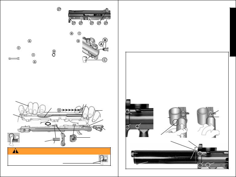
Upper Receiver Disassembly: (continued from page 25)
|
|
3) Remove the 5 receiver bolts |
(4 |
|
|
|
|
|
|
|
|
|
|
|
|
|
|
|
|
|
|||||||||||||||||||||||
E |
|
on ResponseTM Marker) holding the upper |
|
|
|
|
|
|
|
|
|
|
|
|
|
|
|
|
|
||||||||||||||||||||||||
|
receiver halves together. |
|
|
|
|
|
|
|
|
|
|
|
|
|
|
|
|
|
|
|
|
|
|
||||||||||||||||||||
N |
|
To reassemble upper receiver follow the |
|
|
|
|
|
|
|
|
|
|
|
|
|
|
|
|
|
||||||||||||||||||||||||
|
Upper Receiver Assembly instructions below. |
|
|
|
|
|
|
|
|
|
|
|
|
|
|
|
|
|
|||||||||||||||||||||||||
G |
|
Upper Receiver Assembly |
|
|
|
|
|
|
|
|
|
|
|
|
|
|
|
|
|
|
|
|
|
|
|||||||||||||||||||
|
|
|
|
|
|
|
|
|
|
|
|
|
|
|
|
|
|
|
|
|
|
|
|||||||||||||||||||||
L |
|
|
|
|
|
|
|
|
|
|
|
|
|
|
|
|
|
|
|
|
|
|
|
|
|
|
|
|
|
|
|
|
|
|
|
|
|
|
|
|
|
||
|
|
For ResponseTM Marker only: Install two parts |
& |
|
to the right receiver |
|
|||||||||||||||||||||||||||||||||||||
|
|
|
|||||||||||||||||||||||||||||||||||||||||
I |
|
|
half before assembling receiver halves. |
|
|
|
|
|
|
|
|
|
|
|
|
|
|
|
|
||||||||||||||||||||||||
|
|
|
|
|
|
|
|
|
|
|
|
|
|
|
|
|
|
||||||||||||||||||||||||||
S |
|
|
1) Oil o-ring |
of the exterior flow control adapter . |
|
|
|
|
|
|
|
|
|
|
|
||||||||||||||||||||||||||||
|
|
|
|
|
|
|
|
|
|
|
|
||||||||||||||||||||||||||||||||
|
|
2) Align threaded opening of interior flow connector |
|
|
|
|
|
|
|
|
|
|
|
||||||||||||||||||||||||||||||
|
|
|
|
|
|
|
|
|
|
|
|
||||||||||||||||||||||||||||||||
H |
|
|
fitting |
|
|
to inside of right receiver half. |
|
|
|
|
|
|
|
|
|
|
|
|
|
|
|
|
|||||||||||||||||||||
|
|
|
3) Carefully thread adapter |
through the right |
|
|
|
|
|
|
|
|
|
|
|
||||||||||||||||||||||||||||
|
|
|
|
|
|
|
|
|
|
|
|
|
|||||||||||||||||||||||||||||||
|
|
|
receiver half into |
and tighten |
with a 3/8” wrench |
|
|
|
|
|
|
|
|
|
|
|
|||||||||||||||||||||||||||
|
|
|
|
|
|
|
|
(do not overtighten and strip threaded parts |
|
|
|
|
|
|
|
|
|
|
|
||||||||||||||||||||||||
|
|
|
|
|
|
|
|
|
|
|
|
|
|
|
|
|
|
||||||||||||||||||||||||||
|
|
|
|
|
|
|
|
|
|
|
|
|
|
|
|
|
|
|
|||||||||||||||||||||||||
|
|
|
or damage o-ring |
). |
|
|
|
|
|
|
|
|
|
|
|
|
|
|
|
|
|
|
|
|
|
|
|
|
|
|
|
|
|||||||||||
|
|
|
|
|
|
|
|
|
|
|
|
|
|
|
|
|
|
|
|
|
|
|
|
|
|
|
|
|
|
|
|
|
|
|
|
|
|
|
|
|
|
|
|
1) Make sure all parts are clean before reassembling. Place right upper receiver half flat with Tombstone Latch & Spring, Front Grip Nut, Receiver O-ring and Ball Latch in position as shown below.
2) With left hand, grip left upper 3) With left hand holding as shown below, receiver half as shown to hold use right hand to seat cocking handle with Cocking Handle and spring in place spring into receiver cutout then position by applying side pressure with edge of spring in end of spring cutout index finger pushing in direction of bowed as shown below. Then grip left arrows  against Cocking Handle. receiver with right hand as shown.
Right |
|
Cocking Handle Spring |
Cocking Handle |
||||
Hand |
|
|
|
will be |
|||
|
|
|
|
bowed. |
|
|
Left |
Left |
|
|
|
|
|
|
Hand |
|
|
|
|
|
|
|
|
Half |
|
|
|
|
|
|
Right |
|
|
|
|
|
|
|
|
Receiver O-ring |
|
|
|
|
Half |
||
|
|
|
|
Ball |
|||
|
|
|
|
|
|
|
|
|
|
|
|
|
|
|
Latch |
|
|
Tombstone |
|
|
Front Grip Nut |
||
|
|
Latch & Spring |
|
Latch |
with flat side facing |
||
|
|
|
|||||
|
|
properly inserted Spring |
|
bottom of marker. |
|||
|
|
||||||
WARNING
DO NOT REASSEMBLE WITHOUT MAKING SURE
TOMBSTONE LATCH & SPRING ARE PROPERLY
INSERTED IN PLACE AS SHOWN.
4) Use your finger tips to guide the left half straight down on to the right half
26 |
Upper Receiver Assembly |
(continued on page 27) |
Upper Receiver Assembly (continued from page 26)
until receiver halves fit flush. If it does not fit flush the first time, check to make sure the spring and other parts have stayed in place and repeat until halves fit flush.
5)Insert 5 (4 on ResponseTM Marker) Receiver Bolts  (not front sight bolt yet) & tighten them just enough to hold halves flush yet loose enough to allow you to now insert and twist Barrel / Adapter unit (or FLATLINETM) clockwise
  to reinstall.
6)Insert Front Sight with its slot facing back of marker, into the top front of the receiver and insert the front sight bolt to hold in place.
7)Make sure all receiver bolts are tight (do not overtighten & strip threads).
FLATLINETM Barrel Removal & Installation
First follow Unloading Your Marker and Air Supply Cylinder Removal instructions on pages 18-20. Never disassemble a marker that is under pressure or pressurize a partially assembled marker.
FlatlineTM Barrel Removal:
Loosen 3 receiver bolts (A, B & C - see below) then turn barrel / adapter to left and remove as one piece from upper receiver.
FlatlineTM Barrel Installation:
1) Loosen 3 |
2) Position the Barrel |
receiver bolts |
Adapter cap screw |
(A, B, & C). |
facing to the left toward |
|
the feeder housing and |
|
insert into receiver. |
AFeeder Housing
B |
C |
Cap |
|
|
screw |
|
|
to the |
|
|
left |
3) Turn the Barrel Assembly 1/4 turn to the right until the adapter cap screw aligns with the front sight.
4) While keeping cap screw and front sight aligned, tighten the 3 receiver screws A, B & C
to complete the installation.
|
Barrel at top |
Proper |
A |
|
Proper screw position |
screw |
|
|
|||
|
position |
B |
C
Properly installed barrel will look like this.
27
E N G L I S H
 Loading...