


|
TIPPMANN |
MARKER LINE |
BACK COVER BLANK |
® |
98 CUSTOMTM |
•Owner’s Manual - For Markers with or without 
•Le Manuel du Propriétaire - Pour les marqueurs avec ou sans 
•Manual del Usuario - Para Marcadores con o sin 
98 CUSTOMTM
BASIC
98 CUSTOMTM
WITH E-TRIGGERTM
98 CUSTOMTM
RESPONSETM
98 CUSTOMTM
CAMOUFLAGE
98 CUSTOMTM
SILVER
98 CUSTOM PROTM
BASIC
98 CUSTOM PROTM
WITH E-TRIGGERTM
98 CUSTOM PROTM
RESPONSETM
98 CUSTOM PROTM
CAMOUFLAGE
TP04300
Date 05-07

|
|
|
E |
|
WARNING |
|
THIS IS NOT A TOY. MISUSE MAY CAUSE SERIOUS |
|
N |
|
INJURY OR DEATH. EYE, FACE AND EAR PROTECTION |
G |
|
DESIGNED FOR PAINTBALL MUST BE WORN BY THE |
|
USER AND ANY PERSON WITHIN RANGE. WE |
|
L |
|
RECOMMEND AT LEAST 18 YEARS OLD TO PURCHASE. |
I |
|
PERSONS UNDER 18 MUST HAVE ADULT SUPERVISION |
S |
|
WHEN USING THIS PRODUCT. READ THE OWNER’S |
H |
|
MANUAL BEFORE USING THIS PRODUCT. |
|
|
|
|
|
|
|
|
|
F |
AVERTISSEMENT |
CE N’EST PAS UN JOUET. L’USAGE IMPROPRE PEUT |
|
R |
CAUSER LA BLESSURE SÉRIEUSE OU LA MORT. LA |
A |
PROTECTION POUR LES YEUX, LE VISAGE ET LES |
N |
OREILLES CONSTRUITE POUR LA BALLE DE PEINT |
DOIT ÊTRE PORTÉE PAR L’UTILISATEUR ET N’IMPORTE |
ÇQUELLE PERSONNE DANS LE CHAMP DE TIR. NOUS
A |
RECOMMENDONS QU’ ON A DIX – HUIT ANS AU MOINS |
I |
POUR L’ACHETER. LES PERSONNES SOUS L’ÂGE DE |
DIX – HUIT ANS DOIVENT AVOIR LA SUPERVISION D’ |
|
S |
UN ADULTE QUAND ON EMPLOIE CE PRODUIT. IL FAUT |
|
LIRE TOUT DE CE MANUEL AVANT DE L’UTILISER. |
|
|
|
E |
|
ADVERTENCIA |
|
ESTO NO ES UN JUGUETE. UN USO INAPROPIADO |
|
S |
|
PUEDE CAUSAR SERIAS HERIDAS O LA MUERTE. |
P |
|
OJOS, CARA Y OIDOS DEBEN SER PROTEGIDOS TODO |
A |
|
EL TIEMPO, CON LA PROTECCIÓN DISEÑADA PARA |
|
PAINTBALL TANTO PARA JUGADORES COMO PARA |
|
Ñ |
|
CUALQUIER PERSONA QUE ESTE EN EL RADIO DE |
O |
|
ALCANCE. RECOMENDAMOS AL MENOS 18 AÑOS |
L |
|
PARA LA COMPRA Y USO. LAS PERSONAS MENORES |
|
|
DE 18 AÑOS DEBEN USAR ESTE PRODUCTO BAJO LA |
|
|
SUPERVISIÓN DE UN ADULTO. ANTES DE USAR ESTE |
|
|
PRODUCTO LEA EL MANUAL DEL USUARIO. |
|
|
|
|
|
|
|
|
|
|
WARNING |
|
|
|
E |
SAFETY IS YOUR RESPONSIBILITY |
|
||||
READ, FAMILIARIZE |
|
|
|
|
N |
YOURSELF AND ANY |
|
|
|
|
G |
OTHER USER OF THIS |
|
ALWAYS KEEP |
|
||
MARKER WITH THE |
ALWAYS KEEP |
|
L |
||
SAFETY INSTRUCTIONS |
BARREL SLEEVE |
|
|||
IN THIS MANUAL. |
TRIGGER SAFETY |
INSTALLED WHEN |
|
I |
|
FOLLOW THESE |
IN SAFE MODE |
NOT IN SHOOTING |
|
||
INSTRUCTIONS WHEN |
UNLESS FIRING |
SITUATION AS |
|
S |
|
USING, WORKING ON, |
AS DETAILED IN |
DETAILED IN |
|
H |
|
TRANSPORTING OR |
INSTRUCTIONS |
INSTRUCTIONS |
|
||
STORING THIS MARKER. ON PAGE 4. |
ON PAGE 2. |
|
|
||
|
|
|
|
|
|
AVERTISSEMENT |
|
F |
|||
SÉCURITÉ EST VOTRE RESPONSABILITÉ |
|
||||
IL FAUT LIRE, VOUS |
|
|
|
|
R |
FAMILIARISER ET |
|
|
|
|
|
TOUS LES AUTRES |
|
|
|
|
A |
UTILISATEURS DE |
|
IL FAUT |
|
||
CE MARQUEUR AVEC |
IL FAUT TOUJOURS |
|
N |
||
LES INSTRUCTIONS |
TOUJOURS |
|
|||
DE SÉCURITÉ DANS CE |
GARDER LA |
GARDER LA |
|
Ç |
|
MANUEL. SUIVEZ CES |
DÉTENTE DANS UNE |
CHEMISE DU |
|
A |
|
INSTRUCTIONS QUAND |
MODE DE SÉCURITÉ |
CANON INSTALLÉE |
|
||
VOUS UTILISEZ, |
SAUF QUAND ON |
QUAND ON NE |
|
I |
|
TRAVAILLEZ SUR, |
TIRE COMME |
TIRE PAS COMME |
|
||
TRANSPORTEZ, OU |
DÉTAILLÉE DANS |
DÉTAILLÉE DANS |
|
S |
|
ENTREPOSEZ CE |
LES INSTRUCTIONS |
LES INSTRUCTIONS |
|
||
MARQUEUR. |
À LA PAGE 3. |
À LA PAGE 1. |
|
|
|
|
|
|
|
||
ADVERTENCIA |
|
|
E |
||
LA SEGURIDAD ES SU RESPONSABILIDAD |
|
||||
EL PROPIETARIO Y |
|
|
|
|
S |
TODA PERSONA QUE |
|
|
|
|
P |
VA A USAR ESTE |
|
|
MANTENGA |
|
|
MARCADOR DEBE LEER Y |
|
|
A |
||
FAMILIARIZARCE CON |
MANTENGA SIEMPRE |
LA FUNDA |
|
||
LAS INSTRUCCIONES DE EL SEGURO DEL |
|
DE SEGURIDAD |
|
Ñ |
|
SEGURIDAD EN ESTE |
GATILLO ACTIVADO |
INSTALADA |
|
O |
|
MANUAL. SIGA LAS |
A MENOS QUE SEA |
|
CUANDO NO |
|
|
INSTRUCCIONES DE |
NECESARIO HACER |
|
ESTE HACIENDO |
|
L |
USO, MANTENIMIENTO, |
DISPAROS. COMO |
|
DISPAROS |
|
|
TRANSPORTE Y |
SE VE EN LAS |
|
COMO SE |
|
|
ALMACENAJE DE |
INSTRUCCIONES |
|
ILUSTRA EN |
|
|
ESTE MARCADOR. |
DE LA PÁGINA 3. |
|
LA PÁGINA 1. |
|
|
|
|
|
|
|
|

E |
WARNING |
THIS IS NOT A TOY. MISUSE MAY CAUSE SERIOUS |
|
N |
INJURY OR DEATH. EYE, FACE AND EAR PROTECTION |
G |
DESIGNED FOR PAINTBALL MUST BE WORN BY THE |
L |
USER AND ANY PERSON WITHIN RANGE. WE |
RECOMMEND AT LEAST 18 YEARS OLD TO PURCHASE. |
|
I |
PERSONS UNDER 18 MUST HAVE ADULT SUPERVISION |
S |
WHEN USING THIS PRODUCT. READ THE OWNER’S |
H |
MANUAL BEFORE USING THIS PRODUCT. |
|
WARNING
BARREL SLEEVE INSTALLATION
• EXCEPT WHEN YOUR MARKER IS IN USE, ALWAYS MAKE SURE THAT THE TRIGGER SAFETY IS IN SAFE MODE (SEE INSTRUCTIONS ON PAGE 4), AND THE BARREL SLEEVE IS PROPERLY INSTALLED ON YOUR MARKER AS SHOWN BELOW.
1) SLIDE BARREL INTO SLEEVE AND LOOP CORD OVER TOP OF RECEIVER AND POSITION AT BACK OF GRIP AS SHOWN
BELOW. |
|
CORD |
|
|
LENGTH |
||
|
ADJUSTOR |
||
|
BUTTON |
||
|
|
|
|
2)PINCH CORD LENGTH ADJUSTOR BUTTON AND HOLD TO BACK OF GRIP AS
YOU PULL CORD THROUGH IT UNTIL ADJUSTOR IS SNUG AGAINST BACK OF GRIP, THEN RELEASE BUTTON.
3)CHECK TO BE SURE YOU LEAVE ENOUGH CORD ELASTICITY TO PULL CORD/ADJUSTOR UP OVER TOP OF MARKER TO REMOVE BARREL SLEEVE FOR FIRING.
4)AFTER CORD LENGTH IS
ADJUSTED, LOCK CORD LENGTH BY TYING A KNOT IN THE CORD AGAINST THE BACK OF THE ADJUSTOR AS SHOWN.
2
TIPPMANN®
2955 Adams Center Road, Fort Wayne, IN 46803 USA P) 260-749-6022 • F) 260-749-6619 • www.tippmann.com
CONGRATULATIONS on your purchase of a Tippmann® paintball marker. We believe our 98 CustomTM line of markers to be the most accurate and durable paintball markers available, and are proudly manufactured in the USA. All Tippmann® 98 CustomTM line markers from the non-  98 Custom model to our
  enabled 98 CustomTM and 98 Custom ProTM models will give many years of dependable service if cared for properly. The
  enabled models contain our exclusive new Anti-Chop Technology, a patent pending design to help eliminate ball chopping and ensure consistent performance. Using a new technology that has the front and rear bolt working independently of each other,
  virtually eliminates ball chopping and improves ball accuracy with less barrel cleaning; and unlike other anti-chop systems, our system maintains consistent ball velocity shot after shot and does not have to be re-cocked if the anti-chop technology had to be engaged.
Please take time to read this manual thoroughly and become familiar with your 98 CUSTOMTM model’s parts, operation, and safety precautions before you attempt to load or fire this marker. If you have a missing or broken part or need assistance, please contact Tippmann® Consumer Relations at 1-800-533-4831 for fast friendly service.
TABLE OF CONTENTS |
|
Warning/Caution ........................................................................................... |
2 |
Warning/Caution Barrel Sleeve Installation ........................................... |
2 |
Warning/Liability Statement ....................................................................... |
4 |
Safety is your Responsibility / Familiarize Yourself With Safety ...... |
4 |
Safe Mode = Turning The Safety On (PUSH SAFE) ............................ |
4 |
Fire Mode = Turning The Safety Off (PUSH FIRE) .............................. |
4 |
Getting Started ............................................................................................. |
6 |
1. Prepare Marker for Air Supply Cylinder Installation ................... |
6 |
2. Air Supply Cylinder Installation ....................................................... |
6 |
3. Hopper Installation ............................................................................. |
7 |
4. Rate of Fire Adjustments and Troubleshooting ........................... |
7 |
5. Velocity Adjustment ............................................................................ |
7 |
6. Rear Sight Adjustment ....................................................................... |
7 |
Schematics .................................................................................................. |
14 |
Specifications ............................................................................................. |
20 |
Unloading Your Marker ............................................................................. |
21 |
Air Supply Cylinder Removal................................................................... |
21 |
Cleaning & Maintenance .......................................................................... |
21 |
Marker Disassembly / Assembly ............................................................. |
22 |
Repairing Air Supply Leaks ..................................................................... |
24 |
Storage ......................................................................................................... |
24 |
Warranty and Repair Policy ..................................................................... |
25 |
Warranty or Repair Procedure ................................................................ |
25 |
Warranty Registration ............................................................................... |
25 |
3
E N G L I S H

Warning/Liability Statement
This marker is classified as a dangerous weapon and is E surrendered by Tippmann Sports, LLC with the understanding that N the purchaser assumes all liability resulting from unsafe handling G or any action that constitutes a violation of any applicable laws or regulations. Tippmann Sports, LLC shall not be liable for personal L injury, loss of property or life resulting from the use of this weapon I under any circumstances, including the intentional, reckless,
S negligent or accidental discharges.
HAll information contained in this manual is subject to change without notice. Tippmann Sports, LLC reserves the right to make changes and improvements to products without incurring any obligation to incorporate such improvements in products previously sold.
If you as a user do not accept liability, Tippmann Sports, LLC requests you do not use a Tippmann Sports, LLC marker. By using this paintball marker you release Tippmann Sports, LLC of any and all liability associated with its use.
SAFETY IS YOUR RESPONSIBILITY!
WARNING
TRIGGER SAFETY ACTIVATION
• EXCEPT WHEN YOUR MARKER |
PUSH SAFE |
IS IN USE, ALWAYS MAKE |
|
SURE THAT THE BARREL SLEEVE |
|
IS INSTALLED (SEE PAGE 2) AND |
|
THE TRIGGER SAFETY |
|
IS IN SAFE MODE WHICH |
|
DISABLES THE TRIGGER. |
|
•TO TURN ON THE SAFETY (SAFE MODE): PUSH THE SAFETY IN AS SHOWN ABOVE.
•TO TURN SAFETY OFF (FIRE MODE): PUSH SAME BUTTON ON OPPOSITE SIDE OF RECEIVER.
FAMILIARIZE YOURSELF WITH SAFETY...
The ownership of this weapon places upon you the total responsibility for its safe and lawful use. You must observe the same safety precautions as you would any firearm to assure the safety of not only yourself but everyone around you. The user
should at all times use caution when using this marker. The sport
4
Safety Is Your Responsibility (continued from page 4) |
|
|
of Paintball will be viewed and judged upon your safe and |
|
|
sportsmanlike conduct. Always remember that the game of |
E |
|
Paintball can only survive and grow if it remains SAFE! |
||
• Do not load or fire this marker until you have completely read |
N |
|
this manual and are familiar with its safety features, mechanical G |
||
operation and handling characteristics. |
L |
|
• Handle this and any marker as if it were loaded at all times. |
||
I |
||
• Keep your finger off the trigger until ready to shoot. |
||
• Do not look down the barrel of a paintball marker. Accidental |
S |
|
discharge into the eyes may cause permanent injury or death. H |
||
•Keep the marker on safe until ready to shoot (see page 4).
•Keep the barrel sleeve installed on marker when not shooting.
•Never point the marker at anything you do not intend to shoot.
•Never fire your marker at anything you do not intend to shoot because there may be balls or foreign debris lodged in the chamber, barrel and / or the marker valve.
•Do not shoot at fragile objects such as windows.
•Never fire your marker at personal property of others, the paintball can stain the paint of automobiles and houses.
•Always keep the muzzle pointed down or in a safe direction, even if you stumble or fall.
•Eye, face and ear protection designed specifically to stop paintballs in the form of goggles and full face mask meeting ASTM Specification F 1776 must be worn by the user and any person within range.
•Never shoot at a person who is not protected by eye, face and ear protection designed for paintball.
•Pressurize and load the marker only when the marker will be immediately used.
•NOTE: Before storing or disassembling be sure to remove paintballs and air supply (see unloading and air supply removal instructions on page 21). Install barrel sleeve (see page 2).
•Store the marker unloaded and degassed in a secure place.
•Do not field strip or otherwise disassemble this marker while
it is pressurized with air supply.
•Dress appropriately when playing the game of paintball. Avoid exposing any skin when playing the game of paintball. Even
a light layer will absorb some of the impact and protect you from the paintballs.
5 |
Safety Is Your Responsibility |
(continued on page 6) |
|
Safety Is Your Responsibility (continued from page 5) |
|
• Keep exposed skin away from escaping gas when installing |
E |
or removing air supply cylinder or if the marker or air supply is |
leaking. Compressed air, CO2, and nitrogen gasses are |
|
N |
very cold and can cause frostbite under certain conditions. |
G |
• Use only .68 caliber paintballs, never load or fire any foreign objects. |
• Avoid alcoholic beverages before and during the use of this |
|
L |
marker. Handling markers while under the influence of drugs |
Sor alcohol is a criminal disregard for public safety.
•Avoid shooting an opponent at point blank, 6 feet or less.
H• Familiarize yourself with instructions listed on air supply cylinder or adaptor. Contact the air supply cylinder or adaptor manufacturer with any questions.
•Always measure your marker’s velocity before playing paintball and never shoot at velocities in excess of 300 feet per second (see instructions on page 7).
GETTING STARTED
Eye protection designed for paintball use must be worn by the user and any person within range.
STEP 1) Prepare Marker for Air Supply Cylinder Installation
•For Models: 98 Custom TM With E-TriggerTM or Custom ProTM With E-TriggerTM - You must first read and follow E-Trigger Operating Instructions (on pages 8-13) before performing STEP 2.
•For 98 Custom TM, 98 Custom ResponseTM, Custom ProTM and Custom ProTM ResponseTM go to STEP 2.
STEP 2) Air Supply Cylinder Installation
•Do not pressurize a partially assembled paintball marker.
•First install barrel sleeve (see instructions on page 2).
•Next put trigger safety in Safe Mode (see instructions on page 4).
•Next you need to cock the marker by sliding the bolt handle all the way back until it locks into place. Always keep marker in the cocked position when air supply is attached to marker. This will help prevent an accidental discharge.
•To install the air supply cylinder, lubricate the cylinder valve o-ring with a
little gun oil then insert the cylinder valve end into the air supply adapter at the back end of the marker grip. Twist the cylinder clockwise  into the marker until it stops. Adjust the butt plate if necessary. Your marker is ready to fire once you switch to Fire Mode from Safe Mode. If the tank is full and you do not hear the air supply engage, the pin valve could be
too short or the pin valve seal is damaged.
6 |
Getting Started (continued on page 7) |
|
Getting Started (continued from page 6) |
|
STEP 3) Hopper Installation |
|
• Barrel Sleeve must be installed (see page 2) and safety in |
E |
Safe Mode (see page 4) before filling the hopper. |
|
• Make sure that the feed elbow and hopper are clean and |
N |
free of any sharp edges to keep paintballs feeding into the |
G |
marker smoothly. |
|
• Install the hopper neck into the feed elbow of your marker |
L |
and tighten the hopper down with a 3/16” allen wrench. |
I |
NOTE: Do not overtighten or the elbow may break. With the barrel |
S |
sleeve installed and safety in Safe Mode, you are now ready to |
H |
load your hopper with paintballs. Fill hopper and only remove |
|
barrel sleeve and turn off the safety when ready to shoot. |
|
|
|
STEP 4) Rate of Fire Adjustments and Troubleshooting
•For RESPONSETM markers - complete Tuning The Response Trigger Rate of Fire instructions (on page 13) before performing STEP 5.
•For E-TRIGGER TM markers - read and follow E-Trigger Operating
Instructions (on pages 8-13); before performing STEP 5.
• For 98 Custom TM and Custom ProTM markers - Go to STEP 5.
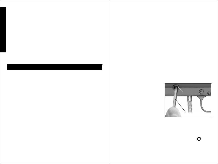
STEP 5) Velocity Adjustment
Each time you play paintball, the velocity of your paintball marker should be checked with a chronograph, an instrument for measuring velocity, prior to playing paintball to verify that the marker’s velocity is set below 300 feet per second or less if required by playing field.
Velocity
Adjustment
Screw
5/32” Allen Wrench
To adjust the velocity use the 5/32” allen wrench included with your marker. The velocity adjustment screw is located on left side receiver. To adjust the velocity down, turn the screw inward or clockwise  . To turn the velocity up, turn the screw out or counterclockwise
  . Do not remove velocity screw.
NOTE: You must turn the velocity screw all the way in before doing any disassembly.
STEP 6) Rear Sight Adjustment
If your paintball is hitting low, slide the rear sight back towards rear
of marker. Do the opposite if paintball is hitting high.
7
|
E-TRIGGERTM OPERATING INSTRUCTIONS |
|
Read And Follow E-TriggerTM Operating Instructions Before Attempting To |
E Operate a Tippmann 98 CustomTM Line Marker With E-TriggerTM. |
|
N |
READ EACH STEP COMPLETELY BEFORE PERFORMING STEP: |
Eye protection designed for paintball use must be worn by the user |
|
G and any person within range. |
|
L |
WARNING |
I |
INSTALL THE AIR SUPPLY AND LOAD THE HOPPER WITH |
S |
PAINTBALLS ONLY AFTER YOU: |
HAVE THE BARREL SLEEVE INSTALLED; |
HHAVE THE SAFETY IN THE "SAFE" POSITION;
HAVE SUCCESSFULLY INSTALLED THE BATTERY AND
ARE FAMILIAR WITH THE E-TRIGGERTM NORMAL OPERATION (STEP 2: AND STEP 3:).
STEP 1: Prepare the marker for safety before any programming:
E-TRIGGERTM Battery Installation or Replacement
1)Prepare the marker for disassembly. First follow the unloading and air supply removal instructions on page 21 and never disassemble a marker that is under pressure.
2)Remove Battery Clip/old battery (from marker). Remove left grip (2 bolts). Carefully work battery out of receiver cutout bringing non-connected
end out first. As you remove battery from receiver, do not rip wires off of internal components. Carefully remove old battery from battery clip connector.
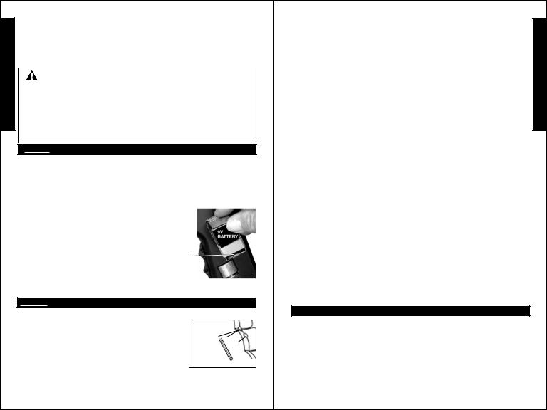
3)Install new battery. Attach 9v battery to
battery connector and be sure wires lay flat inside the cutout area of receiver (as shown on page 23).
Carefully tilt and insert your new battery, wire attached end first, into receiver as shown. Reinstall left receiver grip with 2 grip bolts. Battery installation is complete.
NOTE: The E-Trigger Low Battery Indicator feature: the “Ready To Fire” solid Green LED will turn to blinking red when the battery is low and needs replaced.
STEP 2: NORMAL OPERATION:
1) To Turn ON the E-Trigger to normal operation - Ready To Fire:
• Without holding the trigger: Use a small object
like an allen wrench to press and hold the power |
Power |
button for 1/2 second and then release the power |
Button |
button. The LED should light solid Orange for 2 |
LED |
seconds, flash Red once and then light solid Green |
|
to show normal operation - “Ready To Fire” mode. |
|
Your E-Trigger is now ready to fire in the SEMI-AUTO = 1 pull / release of the trigger fires 1 time (Factory set Default Firing Mode).
NOTE: If pressing the power button failed to turn on the LED light, see |
|
8 |
E-TriggerTM Operating Instructions |
|
(continued on page 9) |
E-TriggerTM Operating Instructions (continued from page 8)
troubleshooting on page 9.
2) To turn OFF the E-Trigger electronics. Press and hold the power button for 2 seconds as the LED turns solid Red, then release the Power Button and the LED will turn OFF. NOTE: The trigger electronics are set to shut-off automatically after a prolonged period of inactivity (120 minutes).
3) To select a new firing mode:
1) Turn ON the E-Trigger to normal operation (solid Green LED - Ready To Fire) as instructed in STEP 2: 1) on page 8.
2) Press / hold the power button in one time for more than 1/4 but less than 2 seconds and release the power button. Count the LED Orange flashes to identify your new setting, the LED light will return to solid Green - Ready To Fire - in the new firing mode. You can program your marker for any one of 5 firing modes. The orange flashes = firing mode options are:
• 1 orange flash = SEMI-AUTO MODE – 1 pull/release of the trigger fires 1 time (default firing mode). (This adheres to the 2005 NPPL rules).
•2 orange flashes = 3 SHOT RAMPING MODE – 3 trigger pulls are required (semi-auto) and the consecutive trigger pulls will fire 3 shots per pull as long as the trigger is pulled at least 5 times per second. (This adheres to the 2005 PSP rules).
•3 orange flashes = 3 SHOT FULL AUTO MODE – 3 trigger pulls are required (semi-auto) after which the trigger can he held to achieve full auto firing. (This adheres to the 2005 NXL rules).
•4 orange flashes = AUTO RESPONSE MODE – Fires one shot for each pull or release of the trigger. If the trigger is held for more than 1/4 of a second,when the trigger is released no shot is fired.
•5 orange flashes = TURBO MODE – Fires one shot for each pull of the trigger until the time between trigger pulls is less than 1/4 of a second at
which point it will fire on each trigger pull and trigger release.Repeat step 2) until you have the firing mode you want.
•You are now ready to go back to page 6 and complete the GETTING STARTED section steps: STEP 2:, STEP 3:, STEP 4:, STEP 5: and STEP 6:. NOTE: If marker does not fire see Troubleshooting on page 10.
TOURNAMENT LOCK: Because the E-Trigger board requires a tool to turn it on and off, no tournament lock is necessary for competition paintball.
E-TRIGGER TROUBLESHOOTING
PROBLEM: The LED light does not light when you push the power button and attempt to turn ON the E-Trigger in STEP 2: Normal Operation.
1)Battery may be disconnected. Check battery clip connection.
2)Battery may be bad - Replace battery.
3)Internal wire may be disconnected. Do NOT disassemble a marker while it is pressurized with air. Inspect wire connections inside the receiver: follow disassembly / wire inspection and assembly instructions on pages 22-24 then continue on page 8 with STEP 2: Normal Operation. NOTE: If a problem still exists, call Tippmann® Service Department at 1-800-533-4831.
9 |
E-TriggerTM Operating Instructions |
(continued on page 10) |
E N G L I S H

E
TMN
G
L
I
S
H
E-TriggerTM Operating Instructions (continued from page 9)
E-TRIGGER TROUBLESHOOTING - Continued
PROBLEM: You have successfully installed the battery, turned on the E-
Trigger, installed the air supply and loaded the paintballs and the marker will not fire. Check to be sure safety is in "FIRE" position and make sure sufficient air supply is hooked up to the marker. If a problem still exists, call Tippmann® Service Department at 1-800-533-4831.
PROBLEM: the “Ready To Fire” solid Green LED has turned to blinking red - The E-Trigger has a Low Battery Indicator feature: the “Ready To
Fire” solid Green LED will turn to blinking red when the battery is low and needs replaced. Replace the battery.
PROBLEMS WHEN FIRING: You can fine tune how your marker fires by making adjustments to the Dwell, Debounce and Rate Of Fire Cap modes. Read and become familiar with detailed descriptions of problems you may have when firing and instructions for troubleshooting, tuning and programming to correct them in the Dwell, DebounceTM and Rate Of Fire sections on pages 10, 11,12 and 13.
STEP 3: How to program a new Dwell, DebounceTM, Rate Of Fire Cap or Firing mode setting In the TRIGGER PROGRAMMING MODE. (Example: Shows how to select a new firing mode).
1)FIRST YOU MUST ENTER INTO THE “TRIGGER PROGRAMMING MODE:” to access the Trigger Programming Menu: Make sure the power is turned off (page 9 step 2). Press the trigger safety to the FIRE position. Pull the trigger and hold it in the back position - as you press and hold the power button for 1 second (the LED will light red) - then release first the power button and then the trigger. The LED will stay solid red indicating the marker is now in the “Trigger Programming Mode” - at Menu Item number 1.
In the “Trigger Programming Mode”, there are 4 Menu Items, each identifiable by its LED color which creates the “Programming Menu” sequence:
• Menu Item 1 - Solid Red LED = Dwell (programming mode).
• Menu Item 2 - Solid Green LED = Debounce (programming mode).
• Menu Item 3 - Flickering Green LED = Rate of Fire (ROF) Cap (programming mode).
• Menu Item 4 - Alternating Green/Orange LED = Firing Mode (programming mode).
2)TO SELECT A MENU ITEM:
Pull and release the trigger to advance to the next menu item until you get to the item you want to change. After last item, an additional trigger pull will restart the menu item sequence. (EXAMPLE: To program a new Firing Mode, advance to: Alternating Green/Orange LED=Firing Mode).
3) TO CHECK THE MENU ITEM’S CURRENT SETTING:
Pull the trigger and hold it until the LED goes out and then release the trigger. There will be a 2 second pause and then the LED will flash green -
count the number of green flashes to determine the current setting. EXAMPLE-Firing Mode settings (green LED flashes =):
• 1 LED flash = Semi-auto (2005 NPPL legal). |
E-TriggerTM Operating Instructions |
10 |
(continued on page 11) |
E-TriggerTM Operating Instructions (continued from page 10)
•2 LED flashes = 3 shot Ramping (2005 PSP legal).
•3 LED flashes = 3 shot Full Auto (2005 NXL legal).
•4 LED flashes = Auto Response.
•5 LED flashes = Turbo.
If you decide not to change the item’s setting, simply do not touch the trigger at all for 5 seconds. The LED will then blink green/red alternately to indicate there was no reprogramming, and then it will go back to the programming menu and the menu item’s setting will not have changed.You can exit the programming mode by pressing the power button until the LED turns solid red ( then stop pressing button) and LED will turn off.
4) TO CHANGE A MENU ITEM’S SETTING:
Once the LED is done flashing the current setting, there is a 5 second time period to begin programming the new setting (Note: you do not have to wait and count the flashes for the current setting, any trigger input immediately bypasses the flashes and begins programming the new setting). Pull and release the trigger the number of times equal to how you wish to program the item. On each pull of the trigger, the LED will light up red (indicating that the pull has been detected).
Once you have pulled and released the trigger the number of times necessary to set the function, wait a few seconds for Programming Verification.
PROGRAMMING VERIFICATION:
•If the programming was successful: The LED will flash red/green/orange in rapid succession (numerous times) to let you know that the new setting
has been saved. After this, the LED will return to the color representing what the current programming menu item is. At this point, you can exit the programming mode (see below) or you can program other features by once again pulling and releasing the trigger to toggle between Dwell, Debounce™ , ROF Cap, and Firing Mode. (Dwell, Debounce™ and Rate of Fire Cap Programming is described in detail on pages 11, 12 and 13).
•If the programming was unsuccessful, the LED will toggle green/red alternately to indicate there was a programming error, and it will then return
to the programming menu. If this happens the setting will not have changed and you will need to begin programming again at STEP 3: 2). (NOTE: When adjusting the Firing Mode, if you pull and release the trigger more than 5 times it will cause a programming error.)
•To exit the Trigger Programming Mode: Turn off the E-TriggerTM, press and hold the power button until the LED first flickers red then becomes solid red, and then release the button.
DWELL, DEBOUNCETM and RATE OF FIRE (ROF) CAP MODES:
The firing mode controls how the marker fires regardless of these 3 mode settings. Adjust these 3 mode features to fine tune your markers firing as follows.
DWELL troubleshooting and tuning / programming: Dwell is the amount of time that the solenoid will be activated. This time is measured in
milliseconds (1/1000th of a second). The default dwell is 6.0ms.TM |
The lowest |
|
11 |
E-Trigger Operating Instructions |
|
E N G L I S H

E
TMN
G
L
I
S
H
E-TriggerTM Operating Instructions (continued from page 11)
allowable dwell time is 4.0ms and the longest allowable time is 50.0ms. According to the solenoid manufacturer, the dwell should never be below 5.0ms for proper operation. Too short of a dwell time will not release the sear mechanism. Too long of a dwell time will reduce battery life. To adjust the Dwell: Perform STEP 3: 1) then select the Dwell programming feature (= Solid Red LED), pull and hold trigger until LED light goes out and release the trigger. When LED comes back on - count the number of green flashes to determine the current setting and once the LED stops flashing, you have 5 seconds to begin pulling and releasing the trigger once for every FULL 1ms of time you want the dwell to be. On each pull of the trigger, the LED will light up red (indicating that the pull has been detected). Once you have pulled and released the trigger the number of times necessary to set the function, wait a few seconds for Programming Verification (See Programming Verification on page 11).
DEBOUNCETM troubleshooting and tuning/programming: DebounceTM is the amount of time the trigger switch must be stable before checking for another trigger pull. This time is measured in milliseconds. (The default DebounceTM setting is 20ms). If the marker has been double firing, increase the DebounceTM time. To make your marker fire faster, reduce the trigger response time by decreasing the DebounceTM time. To adjust the DebounceTM time: Perform STEP 3 1) then select the DebounceTM programming feature (= Solid Green LED), pull and hold trigger until LED light goes out and release the trigger. When LED comes back on - count the number of green flashes to determine the current setting and once the LED stops flashing, you have 5 seconds to begin pulling and releasing the trigger once for every FULL 1 ms of time you want the DebounceTM to be. On each pull of the trigger, the LED will light up red (indicating that the pull has been detected). Once you have pulled and released the trigger the number of times necessary to set the function, wait a few seconds for Programming Verification (See Programming Verification on page 11).
THE RATE OF FIRE (ROF) CAP troubleshooting and tuning/ programming: (ROF) Cap sets the maximum cycle speed of the marker. (The default ROF Cap is 15 bps). Setting this value too low will reduce the usable speed of the marker. Setting this value too high can cause misfires and “chops” if the hopper can not keep up. To adjust the Rate of Fire cap:Perform STEP 3 1) then select the (ROF) programming feature (=Flickering Green LED), pull and hold trigger until LED light goes out and release the trigger. When LED comes back on - count the number of green flashes to determine the current setting and once the LED stops flashing, you have 5 seconds to begin pulling and releasing the trigger once for every bps you want the Rate of Fire (ROF) cap to be. For example, 20 pulls/releases would be 20 bps. On each pull of the trigger, the LED will light up red (indicating that the pull has been detected). Once you have pulled and released the trigger the number of times necessary to set the function, wait a few seconds for Programming Verification (See
Programming Verification on page 11). |
E-TriggerTM Operating Instructions |
12 |
(continued on page 13) |
|
E-TriggerTM Operating Instructions (continued from page 12)
To Perform A Complete E-Trigger Reset To the Default Settings: |
|
|
|||
With the E-Trigger turned off, press and hold the power button for 10 full |
E |
||||
seconds as the LED turns on solid orange and at 10 seconds it turns solid |
|||||
red. At this point, you release the power button and the LED will turn off and |
N |
||||
the board will be reset to the factory default settings. Your marker is now |
G |
||||
ready for normal operation with the Factory Default Mode Settings: Firing |
|||||
Mode = Semi-auto (1 pull/release of the trigger fires 1 time); Dwell = 6.0 |
L |
||||
ms; DebounceTM = 20 ms; Rate of Fire (ROF) Cap = 15 bps. |
|||||
|
|
|
|
I |
|
NOTE: You can increase your 98 CustomTM or 98 Custom ProTM rate |
|
||||
of fire by adding a CycloneTM Feeder Adapter to your marker. |
|
S |
|||
The CycloneTM Adapter works well with the 98 CustomTM With E-TriggerTM |
|
H |
|||
or 98 Custom ProTM With E-TriggerTM |
when used together. Order the |
|
|||
CycloneTM Adapter Kit PN. T205030. |
|
|
|
|
|
|
|
|
|
|
|
|
|
|
|
||
TUNING THE RESPONSETM TRIGGER RATE OF FIRE |
|
|
|||
With a screwdriver, turn the Flow Control Adjustor |
|
|
|
||
|
|
||||
clockwise |
counterclockwise to increase |
|
|
||
to slow the |
rate of fire to the |
|
|
||
rate of fire. |
|
desired speed. |
|
|
|
|
|
|
|
|
|
Tuning - Troubleshooting A:
If tuning the ResponseTM Trigger produces little or no response in the rate of fire, reset the Flow Control as follows:
1) With marker properly unloaded (see page 21), begin adjusting rate of fire by turning flow control clockwise  completely. Do not over tighten or damage will occur. In a safe direction fire 2 to 4 shots. Trigger should become very hard to pull or even unable to be pulled. If this occurs, the response trigger system is functioning properly. Go to step 2. If it does not occur, go to Troubleshooting B.
2) Now while firing in a safe direction with marker still unloaded, slowly turn the
flow control adjustor counterclockwise  until desired rate of fire is achieved.
Tuning - Troubleshooting B:
If the trigger remains easy to pull after adjusting the flow control, there may be a leak in the system. Double check installation making sure all fittings are tight and o-rings are properly seated. If you need to disassemble to check that all fittings are tight and o-rings are properly seated (see ResponseTM parts on page 20), do not disassemble this marker while it is pressurized with air, follow disassembly / assembly instructions on pages 22-23. If a problem still exists, call Tippmann® Service Department at 1-800-533-4831.
NOTE: To disable the ResponseTM System: First follow the unloading and air supply removal instructions on page 21 and never disassemble a marker that is under pressure. Remove the banjo fitting (20-07) attached to the power tube/valve and replace it with the shut off plug (TA05021).
13

Basic Parts List (WITHOUT  )
)
E
N
G
L
I
S
H
14
WARNING |
E |
DO NOT DISASSEMBLE THIS MARKER WHILE IT IS PRESSURIZED |
|
WITH AIR. DO NOT PRESSURIZE A PARTIALLY ASSEMBLED MARKER. |
N |
TIPPMANN® |
G |
1-800-533-4831 |
L |
www.tippmann.com |
I |
|
S |
|
H |
15


 Basic Parts List
For 98 CustomTM ResponseTM parts or 98 CustomTM With E-TriggerTM parts see page 20.
E
N
G
L
I
S
H
16
WARNING
DO NOT DISASSEMBLE THIS MARKER WHILE IT IS PRESSURIZED WITH AIR. DO NOT PRESSURIZE A PARTIALLY ASSEMBLED MARKER.
TIPPMANNTM
1-800-533-4831 www.tippmann.com
17
E N G L I S H


 Basic Parts List
For Custom ProTM ResponseTM parts or Custom ProTM With E-TriggerTM parts see page 20.
E
N
G
L
I
S
H
18
WARNING |
|
E |
DO NOT DISASSEMBLE THIS MARKER WHILE IT IS PRESSURIZED |
|
|
WITH AIR. DO NOT PRESSURIZE A PARTIALLY ASSEMBLED MARKER. |
|
N |
TIPPMANNTM |
G |
|
1-800-533-4831 |
|
L |
www.tippmann.com |
I |
|
|
|
S |
|
|
H |
|
|
|
|
|
|
19
|
|
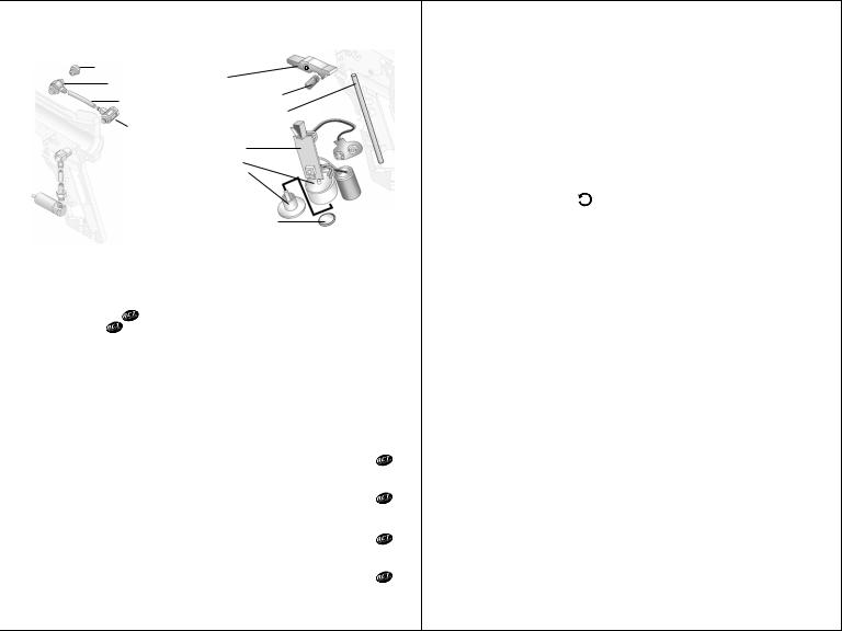
Model Specific Parts Not Shown on schematics (pages 14-19) |
||||||||||||||
|
|
|||||||||||||||
E |
|
RESPONSETM Parts |
|
|
E-TRIGGERTM Parts |
|
||||||||||
|
|
|
|
|
TA05021 Shut Off Plug |
|
|
|
TA01135 |
|
||||||
N |
|
|
|
|
|
|
|
20-07 Banjo Fitting |
|
|
|
|
Sear |
|
||
G |
|
|
|
|
|
|
|
02-87 1/16” Hose |
|
|
|
02-88 Sear Spring |
|
|||
|
|
|
|
|
|
|
|
|
98-91 Armature Pin |
|
||||||
L |
|
|
|
|
|
|
|
|
|
|
|
|
||||
|
|
|
|
|
|
|
|
|
|
|
TA99007 |
|
||||
I |
|
|
|
|
|
|
|
20-03 Flow Control |
|
|
|
|||||
|
|
|
|
|
|
|
|
|
|
|
Sear Tripper |
|
||||
S |
|
|
|
|
|
20-04 90 Degree Fitting |
|
|
Assembly |
|
||||||
|
|
|
|
|
|
|
Solenoid |
|
||||||||
|
|
|
|
|
|
|||||||||||
H |
|
|
|
|
|
|
|
|
20-19 1/8” Hose |
|
|
-Armature |
|
|||
|
|
|
|
|
|
|
|
|
|
fits |
|
|||||
|
|
|
|
|
|
|
20-05 Cylinder Fitting |
|
|
inside bottom |
|
|||||
|
|
|
|
|
|
|
|
|||||||||
|
|
|
|
|
|
|
|
20-02N RT Cylinder |
|
|
of solenoid |
|
||||
|
|
|
|
|
|
|
|
|
|
TA05014 Magnet |
|
|||||
|
|
|
|
|
|
|
|
|
|
|
|
|
||||
|
|
|
|
|
|
|
|
|
|
|
|
|||||
|
|
|
|
|
|
|
||||||||||
|
|
98 CustomTM Line Specifications |
|
|||||||||||||
|
|
Model Basic |
|
....................... |
|
|
|
Tippmann ® 98 CUSTOM TM / |
98 CUSTOM PROTM |
|||||||
|
|
Caliber ............................................................................................................ |
|
|
|
|
|
|
|
|
|
|
|
.68 |
||
|
|
Action ............................................... |
|
|
|
|
|
Semi-Automatic (open bolt blow-back) |
||||||||
|
|
Power/Air Supply ...................................... |
|
|
|
|
|
compressed air, nitrogen or CO2 |
||||||||
|
|
Hopper Capacity ....................................................................... |
|
|
|
|
|
|
200 Paintballs |
|||||||
|
|
Ball Feed (Without |
|
|
|
|
|
|
Gravity |
|||||||
|
|
Ball Feed (With ) |
................ Gravity / Tippmann ® Anti - Chop Technology |
|||||||||||||
|
|
Cycle Rate ......................................................................... |
|
|
|
|
|
|
|
|
|
|
8 shots per second |
|||
|
|
Standard Barrel Length 98 CustomTM .................................. |
8.5” / 21.59 cm |
|||||||||||||
|
|
Overall Length 98 CustomTM (with standard barrel & no tank) |
.. 19.63” / 48.86 cm |
|||||||||||||
|
|
Weight 98 CustomTM |
(without tank) |
|
.................................... |
|
|
|
2.9 lbs. / 1.32 kg |
|||||||
|
|
Standard Barrel Length 98 Custom ProTM ................................. |
11” / 28 cm |
|||||||||||||
|
|
Overall Length 98 Custom ProTM (with standard barrel & no tank) 21” / 53.34 cm.... |
||||||||||||||
|
|
Weight 98 Custom ProTM (without tank) ............................. |
3.1 lbs. / 1.41 kg |
|||||||||||||
|
|
Effective Range ............................................................. |
|
|
|
|
|
150+ ft. / 46+ mètres |
||||||||
|
|
Velocity ....... |
Always measure your marker’s velocity before playing paintball and |
|||||||||||||
|
|
never shoot at velocities in excess of 300 feet per second (see instructions on page 7). |
||||||||||||||
|
|
Model Specific ........................... |
Tippmann ® 98 CUSTOM TM RESPONSETM |
|||||||||||||
|
|
Cycle Rate ........................................................................... |
|
|
|
|
|
|
|
|
|
|
15 shots per second |
|||
|
|
Weight (without tank) |
|
|
|
|
|
|
2.85 lbs. / 1.29 kg |
|||||||
|
|
Model Specific ................ |
Tippmann ® 98 CUSTOM TM WITH E-TRIGGERTM |
|||||||||||||
|
|
Cycle Rate .................................................. |
|
|
|
|
|
|
|
|
|
|
Adjustable 10-30 shots per second |
|||
|
|
Weight (without tank) |
|
|
|
|
|
|
3 lbs. / 1.36 kg |
|||||||
|
|
Model Specific ....................... |
Tippmann ® CUSTOM PRO TM RESPONSETM |
|||||||||||||
|
|
Cycle Rate ........................................................................... |
|
|
|
|
|
|
|
|
|
|
15 shots per second |
|||
|
|
Weight (without tank) ................................................................ |
|
|
|
|
|
|
3.2 lbs. / 1.45 kg |
|||||||
|
|
Model Specific ............ |
Tippmann ® CUSTOM PRO TM WITH E-TRIGGERTM |
|||||||||||||
|
|
Cycle Rate .................................................. |
|
|
|
|
|
|
|
|
|
|
Adjustable 10-30 shots per second |
|||
|
|
Weight (without tank) .................................................................. |
|
20 |
3.3 lbs. / 1.5 kg |
|||||||||||
|
|
|
|
|
|
|
|
|
|
|
|
|||||
|
|
|
|
|
|
|
|
|
|
|
|
|
|
|
|
|
Unloading Your Marker Eye protection designed for paintball |
|
|
|
||
use must be worn by the user and any person within range. |
E |
|
To unload your marker: |
1) Install the barrel sleeve (see page 2). |
|
2) Empty and remove the hopper. 3) Go to a designated firing |
N |
|
area and remove the barrel sleeve. 4) Point your marker in a safe |
||
direction and fire several times to be sure there are no balls lodged in the |
G |
|
chamber and / or barrel. IMPORTANT: Do not uncock your marker as |
L |
|
uncocking your marker may push a ball into the chamber or down into the |
||
barrel in which case the ball will be hidden from view. 5) Install the barrel |
I |
|
sleeve (see page 2). 6) Visually inspect the chamber for paintballs. |
S |
|
Air Supply Cylinder Removal Eye protection designed for |
||
paintball use must be worn by the user and any person within range. |
H |
|
To remove a charged air supply cylinder, turn the cylinder approximately 3/4 |
|
|
of a turn counterclockwise |
or out. This allows the air supply pin valve to |
|
|
||
close so that no air will enter the marker. Point the marker in a safe direction and fire the remaining gas in the marker by pulling the trigger until the marker stops firing. This may take 4-5 shots.
•If your marker keeps firing after you have turned the tank 3/4 of a turn, the
tank pin valve has not closed yet and you may have to turn the tank counterclockwise  a little further.
•If you turn the tank 3/4 of a turn and it begins to leak before you pull the trigger you have turned it too far and may have damaged the tank o- ring. Because of the variances in tank valve parts, each tank varies slightly on exactly how far it should be turned. If this process does not work the tank pin valve could be too long.
NOTE: Before storing or disassembling be sure to follow Unloading Your Marker and Air Supply Cylinder Removal instructions (see above).Install barrel sleeve (see page 2).
Cleaning & Maintenance To reduce the chance of accidental discharge: First follow unloading and air supply removal instructions above and never disassemble a marker that is under pressure.
•Follow warnings listed on the air supply cylinder for handling and storage.
•Familiarize yourself with instructions listed on air supply cylinder or adaptor. Contact the air supply cylinder or adaptor manufacturer with any questions.
•Do not use any petroleum based cleaning solvents.
•Do not use any cleaning solvents that come in aerosol cans. NOTE: Petroleum based products and aerosol products can damage your markers’ o-rings.
Eye protection must be worn during disassembly / assembly.
•To clean your paintball marker use a damp towel with water to wipe off paint, oil, and debris. Use Tippmann® marker oil or other premium marker oil to maintain your marker in good working condition. Re-oil with a few drops to the front bolt o-ring and rear bolt o-ring. Oil the barrel o-ring and air supply valve o-ring.
•To clean the barrel. Depress front sight and tip out feed elbow. Insert metal tab of cable squeegee into breach, then pull squeegee through
barrel to remove debris.
21
|
|
Marker Disassembly |
|
E |
|
First follow unloading and air supply removal instructions on page 21. |
|
|
Do not pressurize a partially assembled paintball marker. Put the marker in |
||
N |
|
the uncocked position. If your marker is cocked, hold the bolt cocking handle |
|
G |
|
- then pull the trigger and release handle forward to uncock the marker. |
|
|
Eye protection must be worn during disassembly / assembly. |
||
L |
|
NOTE: The barrel and adapter bolts must be removed first. Next, |
|
I |
|
turn the velocity screw in until it stops. |
|
S |
|
|
|
|
Longest bolt |
goes |
|
H |
|
in front grip |
|
|
|
when reassembling. |
|
|
|
Shown with Custom ProTM |
|
|
|
barrel, double trigger, |
|
|
|
double trigger guard, |
|
|
|
drop forward tank adapter / |
|
|
|
gas line. |
|
|
|
NOTE: On 98 Custom marker, short |
|
|
|
adapter bolt |
goes in front when reassembling. |
To remove the left-side receiver , unscrew 6 receiver connection bolts
  /
/ . Then carefully lift the left-side receiver to access the internals. NOTE: The Safety
 will stay on the left-side receiver and should be reassembled the same way.
Once inside, pull the end cap out to remove the guide pin and drive spring. These parts must be removed before the bolt handle will release. Disconnect the linkage arm from the rear and front bolts. Slide the front bolt off the power tube and check the o-ring. Clean and oil the o-ring or if damaged, replace with a new one. Do the same with the rear bolt o-ring.
Power tube and valve removal.
NOTE: Do not remove the gas line fitting unless it is leaking or you need to replace the valve. If you should do so you will need some teflon tape or paste to reinstall it.
• First, you need to complete Marker Disassembly Instructions above.
• Removal: To release the power tube and valve, unscrew the two valve lock bolts on the outer right-side receiver.
•Installation: Apply red loctite #271 sealant to valve lock bolts threads and do not over tighten bolts and strip threads when reinstalling.
Valve removal from power tube: If it is necessary to remove the valve,
22 |
Receiver Disassembly (continued on page 23) |
|
Receiver Disassembly (continued from page 22)
use a wrench to slowly unscrew the gas line fitting. Once the fitting is out, the valve will slide out the back of the power tube.
NOTE: Check the external valve o-ring at this time. If the o-ring is damaged your marker will not function correctly.
Reinstalling valve: Insert valve into power tube, align holes and add teflon tape or paste to gas line fitting threads, slowly screw into valve and snug with wrench.
Reassembling Receiver Halves:
1) Double check that the Trigger Assembly, Front Sight, Front Site Pin, Front Sight Spring, Ball Latch, Front Bolt*, Linkage Arm*, Rear Bolt*/ Bolt Insert (A.C.T. markers have no bolt insert); Bolt Handle; Drive Spring* & Guide Pin*, Buffer O-ring, End Cap, Rear Sight , 2 Tank Adapter Nuts, (plus on A.C.T. markers - the Spring Cup*, Upper Spring (long)*, Upper Spring (short)*, Spring Pin*, and Linkarm Pins*(2); are in place and (*=oiled) (see schematics pages 14 -19 for details if needed).
NOTE: For Markers with E-TriggerTM Only: go to steps 3 and 4).
2)Carefully install the left receiver half (make sure halves fit
flush). Insert 5 short receiver bolts and for ease of installation, tighten the bolt
 over the trigger first. Insert Front Grip and insert the long receiver bolt
  to hold front grip
  . Tighten 6 receiver bolts
 /
/ . Tighten two tank adapter bolts
 (NOTE: on 98 Custom markers short adapter bolt goes in front).
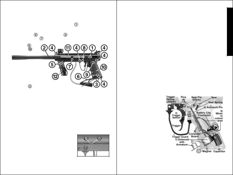
3)Double check E-TriggerTM Parts are Positioned for Reassembly:
Do not operate sear tripper assembly uninstalled as solenoid/armature
may pinch you.
1) Place solenoid / armature into position in right receiver.
2) Carefully align and insert computer board into slot.
3) Place trigger switch on two pins of right receiver half.
4) Insert capacitor in slot.
5) Route wires in cutout areas to lay flat under armature pin and battery and not be pinched
when receiver halves are reassembled.
Visually inspect internal wires for disconnected wire end(s) or damage.
6) Insert armature pin into 2 slots so it moves freely.
7) Insert Magnet in slot below armature as shown.
Double check that all parts are in place as shown.
23 E-TriggerTM Reassembly (continued on page 24)
E N G L I S H
 Loading...