


TIPPMANN®
2955 Adams Center Road, Fort Wayne, IN 46803 USA
P) 260-749-6022 • F) 260-749-6619 www.tippmann.com
PAINTBALL MARKER
LANCEUR DE PAINTBALL
MACADOR PAINTBALL
Owner’s Manual
Manuel d’utilisation Manual del Usuario
TP04220
06/10
E |
|
|
N |
|
|
|
WARNING |
|
G |
|
|
L |
|
|
|
This is not a toy. Misuse may cause serious injury or |
|
I |
|
|
S |
|
death. Eye, face, and ear protection designed for paintball |
H |
|
must be worn by the user and any person within range. |
|
|
We recommend you be at least 18 years old to purchase. |
|
|
Persons under 18 must have adult supervision when |
|
||
|
|
using this product. Read the Owner’s Manual before |
|
|
using this product. |
|
|
AVERTISSEMENT |
|
F |
|||
|
Ceci n’est pas un jouet. Une mauvaise utilisation |
||
R |
|
peut causer de sérieuses blessures ou la mort. Une |
|
A |
|
protection pour les yeux, la tête et les oreilles et étant |
|
N |
|
adaptée au paintball doit être portée par l’utilisateur |
|
Ç |
|
||
A |
|
ainsi que tout utilisateur situé dans le champ de tir. Nous |
|
I |
|
recommandons que l’acheteur ait au moins 18 ans. Les |
|
S |
|
personnes de moins de 18 ans doivent être supervisées |
|
|
|
par un adulte durant l’utilisation de ce produit. Lisez le |
|
|
|
Manuel avant d’utiliser ce produit. |
|
ADVERTENCIA |
|
Esto no es un juguete. Un uso inapropiado puede causar |
|
serias heridas o la muerte. Ojos, cara y oidos deben ser |
E |
protegidos todo el tiempo, con la protección diseñada |
S |
para paintball tanto por jugadores como por cualquier |
P persona que este en el radio de alcance. Recomendamos |
|
Aal menos 18 años para la compra y uso. Las personas
Ñmenores de 18 años deben usar este producto bajo la
Osupervisión de un adulto. Lea el Manual del Usuario antes L de usar este producto.
2

 WARNING
Safety is Your Responsibility
Read and familiarize yourself and any other user of this marker with the safety instructions in this manual. Follow these instructions when using, working on, transporting, or storing this marker.  Always keep the trigger safety in Safe mode
unless firing as detailed in instructions on page 6.
Always keep the barrel blocking device installed when not in a shooting situation,
see instructions on page 4.
E N G L I S H
 AVERTISSEMENT
La Securite est Votre Responsabilite
Lisez et familiarisez-vous ainsi que tout autre utilisateur de ce lanceur avec les instructions de securite contenues dans ce manuel. Suivez ces instructions lorsque vous utilisez, travaillez sur, transportez, ou entreposez ce lanceur.
Si vous ne tirez pas, maintenez toujours la securite de la detente en mode Securite comme indique dans les instructions en page 6.
Gardez toujours le dispositif de blocage du canon installe lorsque vous n’etes pas en situation de tir comme indique dans les instructions en page 4.
F R A N
Ç
A
I
S
 ADVERTENCIA
La Seguridad es Su Responsabilidad
Lea y familiaricese usted y cualquier otro usuario de este marcador con las instrucciones de seguridad de este manual. Siga estas instrucciones cuando se utiliza,
trabajando, transporte, o almacenar este marcador. Mantenga siempre el seguro del gatillo activado
a menos que sea necesario hacer disparos. Como se ve en las instrucciones de la página 6. Mantenga el mecanismo de bloqueo del barril 
 instalado cuando no este haciendo disparos como se ilustra en la página 4.
E S P A
Ñ
O L
3
E |
|
|
N |
|
|
|
|
|
G |
|
WARNING |
L |
|
This is not a toy. Misuse may cause serious injury or |
I |
|
|
S |
|
death. Eye, face, and ear protection designed for paintball |
H |
|
must be worn by the user and any person within range. |
|
|
We recommend you be at least 18 years old to purchase. |
|
|
Persons under 18 must have adult supervision when |
|
|
using this product. Read the Owner’s Manual before |
|
|
using this product. |
 WARNING
Always keep the barrel blocking device installed except when your marker is in use. Always make sure that the trigger safety is in the safe mode (see instructions on page 6) and the barrel blocking device is properly installed on your marker according to the instructions to prevent damage to property, serious injury, or death.
Barrel Blocking Device Installation Instructions
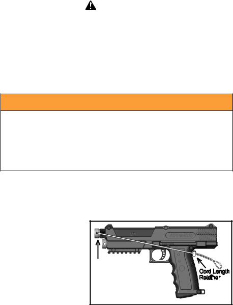
1.Insert the barrel blocking device into the barrel and loop the cord over the top of the receiver and position at the back of the grip as shown.
2.Adjust the cord length retainer up to the back of the grip by pulling the cord back while pushing the cord length retainer toward the marker. Ensure that the cord
length retainer is completely Barrel
tightened against the back of Blocking Cord Length the grip by pulling the cord Device Retainer as tight as possible.
3.To remove barrel blocking device, pull back on center piece of cord length retainer
and slide retainer toward end of cord.
4.Before and after playing, inspect the barrel blocking device. Replace the barrel blocking device if the cord is damaged or there is a loss of cord elasticity.
5.Clean the barrel blocking device with plain, warm water and store out of sunlight in a dry area when not in use.
4

 by TIPPMANN®
2955 Adams Center Road, Fort Wayne, IN 46803 USA P) 260-749-6022 • F) 260-749-6619 • www.tippmann.com
CONGRATULATIONS on your purchase of a Tippmann TPX paintball marker. We believe our TPX markers to be the most accurate and durable paintball markers available. Tippmann TPX markers will provide many years of dependable service if cared for properly.
Please take time to read this manual thoroughly and become familiar with your Tippmann TPX marker’s parts, operation, and safety precautions before you attempt to load or fire this marker. If you have a missing or broken part, or need assistance, please contact Tippmann Consumer Relations at 1-800-533-4831 for fast, friendly service.
TABLE OF CONTENTS |
|
Barrel Blocking Device Installation Instructions...................................................................... |
4 |
Warning/Liability Statement..................................................................................................... |
6 |
Safety Is Your Responsibility! / Familiarize Yourself With Safety............................................ |
6 |
Getting Started........................................................................................................................ |
8 |
1. CO2 Cartridge Installation........................................................................................... |
8 |
2. Removing the Magazine and Loading....................................................................................... |
9 |
3. Firing the Marker......................................................................................................... |
9 |
4. Unloading the Magazine............................................................................................. |
9 |
Velocity Adjustment............................................................................................................... |
10 |
CO2 Cartridge Removal........................................................................................................ |
10 |
Removing an Unused CO2 Cartridge (Non-Punctured)................................................ |
11 |
Removing a Used CO2 Cartridge (Punctured).............................................................. |
11 |
Cleaning & Maintenance....................................................................................................... |
12 |
Magazine Disassembly, Reassembly, and Testing................................................................ |
12 |
Marker Disassembly/Assembly............................................................................................. |
14 |
Firing Valve Disassembly/Assembly ............................................................................. |
15 |
Puncture Valve Disassembly/Assembly........................................................................ |
16 |
Air Valve Disassembly/Assembly.................................................................................. |
16 |
Regulator Disassembly/Assembly................................................................................. |
17 |
Release Pressure From a Marker That Will Not Fire............................................................ |
17 |
Adjustable CO2 Cap..................................................................................................... |
18 |
Additional Information Regarding Performance............................................................ |
18 |
Regulator Pressure Relief Valve Adjustment........................................................................ |
19 |
Troubleshooting..................................................................................................................... |
19 |
Remote Line Adapter (optional equipment)........................................................................... |
21 |
Connecting, Disconnecting, and Removing a Remote Air/CO2 Cylinder...................... |
21 |
Air/CO2 Cylinder Warnings................................................................................................... |
22 |
Air/CO2 Cylinder Safety Tips........................................................................................ |
23 |
Repairing Air/CO2 Cylinder Leaks................................................................................ |
24 |
Storage ................................................................................................................................. |
24 |
Specifications........................................................................................................................ |
25 |
TPX Parts Diagram and Parts List.................................................................................. |
26-28 |
Warranty and Repair Information.......................................................................................... |
29 |
E N G L I S H
5
E |
Warning/Liability Statement |
N |
|
G |
This marker is classified as a dangerous weapon and is surrendered by Tippmann Sports, |
L |
|
I |
LLC with the understanding that the purchaser assumes all liability resulting from unsafe |
handling or any action that constitutes a violation of any applicable laws or regulations. |
|
S |
Tippmann Sports, LLC shall not be liable for personal injury, loss of property or life resulting |
Hfrom the use of this weapon under any circumstances, including intentional, reckless, negligent or accidental discharges.
All information contained in this manual is subject to change without notice. Tippmann Sports, LLC reserves the right to make changes and improvements to products without incurring any obligation to incorporate such improvements into products previously sold.
If you as a user do not accept liability, Tippmann Sports, LLC requests you do not use a Tippmann Sports, LLC marker. By using this paintball marker you release Tippmann Sports, LLC of any and all liability associated with its use.
SAFETY IS YOUR RESPONSIBILITY!
 WARNING
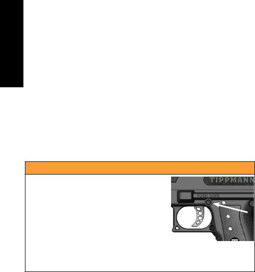
Except when your marker is in use, always make sure that the trigger safety is in Safe mode, and that the barrel blocking device is properly installed (see page 4).
To turn ON the trigger safety (Safe
mode), push in the safety (arrow) as shown above.
To turn OFF the trigger safety (Fire mode), push in the safety from the opposite side of the receiver.
Familiarize Yourself With Safety...
The ownership of this marker places upon you the total responsibility of its safe and lawful use. You must observe the same safety precautions as you would any firearm to assure the safety of not only yourself but everyone around you. Outlined here are some general
precautions to be aware of. The user should at all times use caution and common sense when using this marker and always remember that the game of paintball can only survive and grow if it remains SAFE!
•Do not load or fire this marker until you have completely read this manual and are familiar with its safety features, mechanical operation and handling characteristics.
•Handle this and any marker as if it were loaded at all times.
•Keep your finger off the trigger until you are ready to shoot.
•Do not look down the barrel of a paintball marker. Accidental discharge into the eyes may cause permanent injury or death.
6

•Keep the marker in Safe mode until ready to shoot (page 6).
•Keep the barrel blocking device installed on marker when not shooting (page 4).
•Never point the marker at anything you do not intend to shoot.
•Never fire your marker at anything you do not intend to shoot because there may be paintballs or foreign debris lodged in the chamber, barrel, and/or the marker valve.
•Do not shoot at fragile objects such as windows.
•Never fire your marker at personal property of others. The paintball impact can cause damage and the paint can stain the finish of automobiles, houses, etc.
•Always keep the muzzle pointed down or in a safe direction, even if you stumble or fall.
•Eye, face, and ear protection designed specifically to stop paintballs in the form of goggles and full face mask meeting ASTM Specification F 1776 must be worn by the user and any person within range.
•Never shoot at a person who is not protected by eye, face, and ear protection designed for paintball.
•Pressurize and load the marker only when the marker will be immediately used.
•Store the marker unloaded and degassed in a secure place.
NOTE: Before storing or disassembling, be sure to remove paintballs and air/CO2 supply (see unloading and air/CO2 removal instructions on pages 9 -11) and install the barrel blocking device (see page 4).
•Do not field strip or otherwise disassemble this marker while it is pressurized with air/CO2 supply.
•Dress appropriately when playing the game of paintball. Avoid exposing any skin when playing the game of paintball. Even a light layer will absorb some of the impact and protect you from the paintballs.
•Keep exposed skin away from escaping gas when installing or removing air/CO2 cylinder or if the marker or air/CO2 supply is leaking. Compressed air, CO2, and nitrogen gasses are very cold and can cause frostbite under certain conditions.
•Use only .68 caliber paintballs. Never load or fire any foreign objects.
•Avoid alcoholic beverages before and during the use of this marker. Handling markers while under the influence of drugs or alcohol is a criminal disregard for public safety.
•Avoid shooting an opponent at point blank, 6 feet or less.
•Familiarize yourself with instructions listed on air/CO2 cylinder or adapter. Contact the air/CO2 cylinder or adapter manufacturer with any questions.
•Read the Air/CO2 Cylinder Warnings and Safety Tips on pages 22–24 before beginning the cylinder installation or removal.
•Always measure your marker’s velocity before playing paintball and never shoot at velocities in excess of 300 feet per second (see instructions on page 10).
E N G L I S H
7
E |
Getting Started |
||
N |
|||
G |
• |
Eye protection designed for paintball use must be worn by the user and any person |
|
L |
|||
|
within range. |
||
I |
|
||
• |
Do not disassemble this marker while it is pressurized. |
||
S |
|||
• |
Do not pressurize a partially assembled marker. |
||
H |
|||
• |
Read each step completely before performing the instruction. |
||
|
NOTE: Carefully hand start all threaded parts when assembling, and do not overtighten, as |
||
|
this may potentially strip the threaded parts. In this manual, item numbers of parts are in |
||
|
parentheses. You can also find these item numbers in the Parts Diagram on pages 26-27. |
||
 WARNING
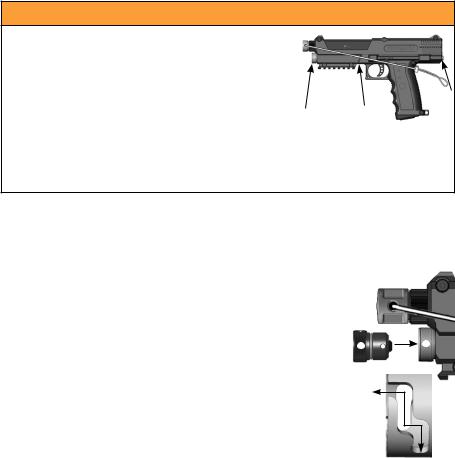
Keep exposed skin away from gas escape points (arrows) when installing 
or removing a CO2 cartridge, or if the marker or air supply is leaking.
Compressed air, CO2, and nitrogen gasses are very cold, and can cause frostbite under certain conditions.
Eye protection designed for paintball use must be worn by the user and any person within range.
1. CO2 Cartridge Installation
If your marker has the optional Remote Line adapter, read the
Air/CO2 Cylinder Warnings, Safety Tips, and Removal on pages 22-24 before beginning the cylinder installation. Do not pressurize a partially assembled marker. Follow the Remote Line instructions starting on page 21, then go to step 2 on page 9.
a.Put the trigger safety in Safe mode (see page 6) and install the barrel blocking device (see page 4).
b.Remove the CO2 Cap. This CO2 Cap has a safety feature. You must push in while turning the CO2 Cap counterclockwise until it stops. Next, pull the CO2 Cap outward and turn counterclockwise again until it stops. The CO2 Cap can now be removed from the marker.
c.Clean the small end of a full 12 gram CO2 cartridge. Insert the small end into the marker.
d.Replace the CO2 Cap. Align the CO2 Cap’s tabs with the slots, push in on the CO2 Cap and turn clockwise until it stops. Push in on the CO2 Cap a second time while turning the CO2 Cap clockwise.
Note: The CO2 cartridge is not punctured during installation. Once you push the trigger safety to Fire mode, the first pull of the Trigger punctures the CO2 cartridge. You can hear the CO2 cartridge pressurize the marker. Your marker is now ready to fire on the next Trigger pull.
IMPORTANT: If your marker begins to leak gas, keep exposed skin away from the escaping gas (the arrows in the WARNING illustration above show gas escape points) and follow CO2 Cartridge Removal instructions on page 10 (on page 21 for markers with a Remote Line
adapter) and then go to Troubleshooting on page 19.
8
NOTE: If your marker does not fire after you have successfully loaded and punctured your CO2 cartridge, put the trigger safety back into Safe mode (see page 4)
and go to Troubleshooting on page 19.
2. Removing the Magazine and Loading
The barrel blocking device must be installed (see page 4) and the trigger safety in Safe mode (see arrow at right and also see page 6).
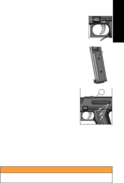
a. To remove the Magazine, push in the Magazine Release button and the Magazine ejects out the bottom of the grip.
b. |
The Ball Carrier inside the Magazine has two tabs, one on each |
|
|
|
side of the Magazine. To load the Magazine, push down on the |
Ball |
|
|
Ball Carrier tabs until the Ball Carrier locks in place near the |
Carrier |
|
|
bottom of the Magazine. (It automatically releases when inserted |
Tab |
|
|
into the marker.) |
|
|
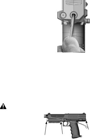
c. |
Keep the Magazine vertical as shown, and insert one paintball at |
|
|
|
a time into the top of the Magazine. The Magazine holds seven |
|
|
|
paintballs. Paintballs in the Magazine are not under pressure |
|
|
|
until the Magazine is inserted into the marker. |
|
|
d. |
To insert a loaded Magazine into the marker, slide the Magazine |
|
|
|
into the grip until you hear it lock into place. Only remove the |
|
|
|
barrel blocking device and change the trigger safety to Fire |
|
|
|
mode when you are ready to shoot. Eye protection |
|
16 |
|
designed for paintball use must be worn by the user and |
||
|
any person within range. The Sight Windows allow you |
|
|
|
to see when you are low on paintballs in the Magazine. |
Sight Windows |
|
|
|
|
|
3. Firing the Marker
Eye protection designed for paintball use must be worn by the user and any person within range. Point the marker in a safe direction. Remove the barrel blocking device from the marker. Move the trigger safety from Safe mode to Fire mode. Pull the Trigger to fire the marker. Each pull of the Trigger fires one paintball
E N G L I S H
4.Unloading the Magazine
a.Eye protection designed for paintball use must be worn by the user and any person within range.
b.Remove the Magazine from the TPX marker. When removing the Magazine, two loose paintballs might drop from the grip. Inspect the breech chamber for a paintball. The Breech Window (16) on top of the receiver provides a way to check for a paintball in the breech chamber. Point the marker in a safe direction and pull
the trigger (dry fire) to clear the marker of any remaining paintballs. Put the trigger safety in Safe mode (see page 6) and install the barrel blocking device (see page 4).
 WARNING
Not seeing a paintball in the Breech Window does not indicate that the marker is unloaded or safe.
c.Push the Magazine’s Ball Carrier down until it locks into place (see step 2.b. above) to take pressure off any remaining paintballs in the Magazine. You can then reload any loose paintballs into the Magazine.
9
E |
|
d. To remove all paintballs from the Magazine, press down on the top of the Carrier |
||
N |
|
|||
G |
|
Release Armature with a flat object, and any remaining paintballs are pushed out |
||
L |
|
the top of the Magazine (Magazine parts are shown on page 13). |
||
|
TIP: For best results and to keep your TPX marker running at peak performance, it is |
|||
I |
|
|||
S |
|
recommended you use a paintball that is not too old or fragile, and is free of dimples or |
||
H |
|
defects. To determine if the paintball is proper for use with the TPX marker, press the tip of |
||
|
|
your fingernail against the paintball to see if it is easily dimpled. Tippmann discourages leaving |
||
|
|
paintballs sitting in Magazines for an extended period of time, as this can lead to the paintball |
||
|
||||
|
|
becoming out of round. Only load Magazines with paintballs on the day of play. |
||
|
|
|
|
|
|
|
Velocity Adjustment |
|
|
|
|
Each time you play paintball, check the velocity of your paintball |
|
|
|
|
marker with a chronograph (an instrument for measuring velocity) |
|
|
|
|
prior to playing paintball. Verify that the marker’s velocity is set below |
|
|
|
|
300 feet per second (or less if required by the playing field). |
|
|
|
|
To adjust the velocity, use the 3/16” Allen wrench included with your |
|
|
|
|
marker. The Velocity Adjustment Screw is located at the back of the |
|
|
|
|
receiver, as shown at right. (Do not use a smaller Allen wrench and |
|
|
|
|
mistakenly adjust the Regulator Pressure Relief Valve Set Screw |
|
|
|
|
which is accessed through the Velocity Adjustment Set Screw - see |
|
|
|
|
|
||
|
|
note below.) To reduce the velocity, turn the screw counterclockwise. To increase the velocity, |
||
|
|
turn the screw clockwise. |
||
|
|
NOTE: This marker has a Regulator Pressure Relief Valve that prevents excessive air/CO2 |
||
|
|
pressure that could damage your marker, and is factory set at 350 psi. If a cartridge with |
||
|
|
excessive air/CO2 pressure is loaded, or if extreme temperature conditions cause excessive |
||
|
|
cartridge pressure buildup, it will vent excessive gas out the access point. Adjust only as |
||
|
|
outlined in the Regulator Pressure Relief Valve Adjustment instructions on page 19. |
||
|
|
CO2 Cartridge Removal |
||
|
|
|
|
|
|
|
WARNING |
|
|
|
|
Keep exposed skin away from gas |
|
|
|
|
escape points (arrows) when installing |
|
|
|
|
or removing a CO2 cartridge, or if the |
|
|
|
|
marker or air supply is leaking. |
|
|
|
|
Compressed air, CO2, and nitrogen |
|
|
|
|
gasses are very cold, and can cause |
|
|
|
|
frostbite under certain conditions. |
|
|
|
|
Eye protection designed for paintball use must be worn |
|
|
|
|
by the user and any person within range. |
|
|
|
|
Do not store or disassemble a marker with the CO2 cartridge (punctured or unpunctured) |
||
|
|
installed. If your marker has an optional remote line adapter kit installed, do not remove the |
||
|
|
CO2 cartridge until you first follow the air/CO2 cylinder removal instructions in the Remote |
||
10
Line Adapter instructions on page 21. Read each step completely before performing the instruction.
Removing an Unused CO2 Cartridge (Non-Punctured)
1.Put the trigger safety in the Safe mode (see page 6) and install the barrel blocking device (see page 4).
2.Press the Magazine Release button (4) and the Magazine (78) ejects out of the grip. NOTE: When removing a loaded Magazine from the marker, two loose paintballs might drop from the grip. Pull the Magazine’s Ball Carrier down until it locks to take pressure off the paintballs, and reload any loose paintballs into the Magazine.
3.Keep the marker pointed in a safe direction, and remove the CO2 Cap (15).
a.Push in and turn the CO2 Cap counterclockwise until it stops. Then pull out until it stops to partially unscrew the cap. NOTE: The cap should be easy to turn; if you are unable to turn it, or if it is difficult to turn, the cartridge has been punctured and you must follow the instructions below, Removing a Used CO2 Cartridge (Punctured).
b.Turn the CO2 Cap a second turn counterclockwise until it stops and pull it out. The empty CO2 cartridge will then slide out.
4.Replace the CO2 Cap. Align the cap pins with the pin guides of the Cap Receiver Insert (14). Push the cap in and turn clockwise. Push the cap in a second time and turn clockwise.
Removing a Used CO2 Cartridge (Punctured)
NOTE: A punctured CO2 cartridge must be emptied before it is removed.
1.Put the trigger safety in Safe mode (see page 6) and install the barrel blocking device (see page 4).
2.Press the Magazine release button (4) and the Magazine (78) ejects out of the grip. NOTE: When removing a loaded Magazine from the marker, two loose paintballs might drop from the grip. Push the Magazine’s Ball Carrier down until it locks to take pressure off the paintballs, and reload any loose paintballs into the Magazine.
3.Go to a designated firing area and remove the barrel blocking device.
4.Point the marker in a safe direction, move the trigger safety to Fire mode, and fire until there is no CO2 left in the cartridge. NOTE: If you have a punctured cartridge in your marker and the marker will not fire, follow the instructions on page 17, Release Pressure From a Marker That Will Not Fire.
5.Put the trigger safety in Safe mode (see page 6) and install the barrel blocking device (see page 4).
6.Visually inspect the chamber for paintballs through the Magazine opening at the bottom of the grip.
7.Keep the marker pointed in a safe direction during CO2 Cap removal.
a.Keep exposed skin away from escaping CO2 - the arrows in the WARNING illustration on page 10 show CO2 escape points. Push in and turn the CO2 Cap slowly counterclockwise until it stops, and pull until it stops to partially unscrew the cap, then wait as any remaining CO2 in the cartridge escapes before performing step (b) (keep exposed skin away from escaping CO2).
b.Turn the CO2 Cap a second turn counterclockwise until it stops and pull it out. The empty cartridge then slides out.
8.Replace the CO2 Cap by aligning the CO2 Cap pins with the pin guides of the Cap Receiver Insert (14) and pushing the Cap in while turning clockwise. Push the Cap in a second time, turn clockwise, and release.
E N G L I S H
11

E
N Cleaning & Maintenance
G |
Always wear eye protection (safety glasses) when cleaning or performing maintenance on |
L |
|
I |
your TPX marker. To reduce the chance of an accidental discharge, follow CO2 Cartridge |
Removal instructions on page 10 (on page 21 for markers with a Remote Line Adaptor). |
|
S |
Never disassemble a marker that is under pressure. Clean and lubricate your marker with |
H |
Tippmann grease after approximately 5000 shots. |
•Familiarize yourself with instructions and follow warnings on CO2cartridge and/or air/CO2 cylinder packaging for use, handling, storage and disposal. Contact the air/ CO2 cylinder manufacturer with any questions.
•Read and follow Air/CO2 Cylinder Warnings and Safety Tips on pages 22-24.
•Petroleum based products and aerosol products can damage marker O-rings. Do not use any petroleum based cleaning solvents. Do not use any cleaning solvents that come in aerosol cans.
•Clean your marker using a damp towel to wipe off paint, grease, and debris.
•To clean inside the barrel, turn the barrel counterclockwise and remove. Push the cable of the squeegee through the barrel, then pull the squeegee through to remove debris.
•To clean the breech and barrel with the Magazine removed, push the cable of the squeegee up into the grip and out the barrel, then pull the squeegee through to remove debris.
•Clean the Magazine with a damp towel to wipe off paint, grease, and debris. Dry springs immediately to help prevent rusting.
•To maintain your marker in good working condition, inspect, clean, and replace any damaged parts. Lubricate as instructed in the following Marker Disassembly/ Assembly section. The best valve O-rings are made of urethane. Urethane O-rings are not affected by high air/CO2 pressures. These may be purchased from Tippmann or your local paintball dealer. Use Tippmann grease to lightly lubricate the O-rings and springs, to maintain your marker in good working condition.
Magazine Disassembly, Reassembly, and Testing
Read these instructions completely before attempting Magazine disassembly or reassembly.
Magazine Disassembly
Refer to the diagram on the next page for these instructions.
1.Set the Magazine on a workbench with the Left Shell side facing up.
2.Remove four #4 x 5/8 Screws.
3.Gently disengage the top hook (arrow in bottom illustration on the next page), then separate both halves of the Magazine.
4.Remove and clean the internal parts as necessary.
NOTE: If you clean the Ball Carrier Spring with water, prevent rusting by thoroughly drying it before reassembly.
12

Magazine Reassembly
1.Place the Carrier Release Lever Spring into the Right Shell.
2.Properly orient the Carrier Release Lever onto the Carrier Release Lever Spring in the Right Shell.
3. Place the Magazine Ball Latch and Carrier Release Armature into the Right Shell.
4. Set the Latch Spring between the Magazine Ball Latch and the Carrier Release Armature. The Latch Spring sets in a pocket formed by the two parts inside the Right Shell.
5. Confirm that the Magazine Ball Latch and Carrier Release Armature are oriented as shown in
the circled area at right. The flat surfaces of the
Magazine Ball Latch and the Carrier Release Armature fit together, and must align correctly for the Magazine to operate properly.
6.Place the Ball Carrier Spring into the Right Shell.
7.Install the Left Shell onto the Right Shell, but do not fully press the two pieces together. Be sure the internal parts stay in their locations while putting the two shell halves together. The top hook (see arrow) of the Right Shell does not engage at this time.
8.Install the bottom #4 x 5/8 Screw. Tighten it until snug.
9.Place the Ball Carrier onto the Ball Carrier Spring (aligning the two tabs on the Ball Carrier with the slots in the Left Shell and Right Shell) and slide down into the top of the assembled shell halves. Push down on the Ball Carrier until it snaps into place inside the Magazine.
10.Push the top of the Magazine together so the top hook engages (arrow below).
11.Install the three remaining #4 x 5/8 Screws. Tighten them until they are snug.
E N G L I S H
|
Ball |
Magazine |
|
|
Carrier |
|
|
|
Ball Latch |
|
|
|
|
|
|
|
Ball Carrier |
|
|
|
Spring |
|
|
|
|
Latch |
|
|
|
Spring |
|
|
|
Carrier |
|
|
|
Release |
|
#4 x 5/8 Screws |
|
Armature |
|
|
Carrier |
|
|
|
|
Release |
Right Shell |
|
|
Lever |
|
|
|
|
|
|
|
Carrier Release |
|
|
Left Shell |
Lever Spring |
|
|
|
|
13

E
N Magazine Testing
G |
1. |
Pull down on the Ball Carrier tabs until the Ball Carrier is about midway down the |
L |
|
Magazine. |
I |
2. While holding onto the Ball Carrier tabs, push down on the Carrier Release Armature |
|
S |
3. |
and ensure that the Magazine Ball Latch moves freely. |
H |
Release the Ball Carrier. The Ball Carrier should move freely when properly |
|
|
|
reassembled. |
|
4. |
Push the Ball Carrier all the way to the bottom of the Magazine until it locks into place. |
|
5. |
Press down on the Carrier Release Armature to release the Ball Carrier. |
Magazine testing is complete.
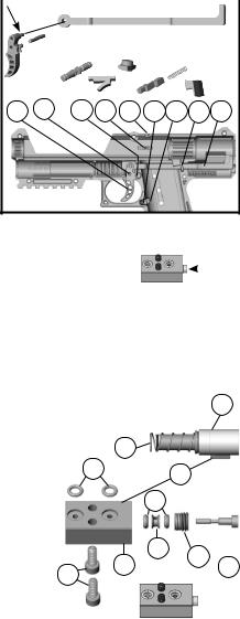
Marker Disassembly/Assembly
Set up a table with plenty of space to work to make sure no small parts become lost. Eye protection must be worn during disassembly and reassembly. Do not disassemble a
pressurized paintball marker. Do not pressurize a partially assembled paintball marker. Follow CO2 Cartridge Removal instructions on page 10 (page 21 if a Remote Line Adapter is installed), leave the CO2 cap (15) off.
1. For Remote Line equipped |
27 |
|
10 |
26 |
9. |
2. |
10 |
|
|
|||||||||||
markers, first remove the |
|
|
|
|
|
|
|
|
|
|
|
|
|
|
|
|
|
|
|
|
Remote Line Adapter by |
|
|
|
|
|
|
|
|
|
|
|
|
|
|
|
|
|
|
|
|
|
|
|
|
|
|
|
|
|
|
|
|
|
|
|
|
|
|
|
|
|
turning it counterclockwise |
15 |
|
|
|
|
|
|
|
|
|
|
|
|
|
|
|
|
|
|
|
on the flats with a 1/2” |
|
|
|
|
|
|
|
|
|
|
|
|
|
|
|
|
|
|
|
|
|
|
|
|
|
|
|
|
|
|
|
|
|
|
|
|
|
|
|
||
wrench, and pull it out. |
|
|
|
|
|
|
|
|
|
|
|
|
|
|
|
|
|
|
|
|
|
|
|
|
|
|
|
|
|
|
|
|
|
|
|
|
|
|
|
|
|
|
|
|
|
|
|
|
|
|
|
|
|
|
|
|
|
|
|
|
|
|
(For reassembly, insert the |
|
|
|
8. |
|
|
|
|
|
|
|
|
|
|
|
|||||
|
|
|
|
|
|
|
|
Remote Line |
||||||||||||
Remote Line Adapter into |
NOTE: |
|
|
|
10 |
|
|
|
|
|
|
|
|
|
|
Adapter |
||||
the hole in the back of the |
|
|
|
|
|
|
|
10 |
|
|
|
|
|
|
||||||
|
|
|
4. |
|
|
|
|
|
|
|
|
|||||||||
marker as shown. Carefully |
Failure to |
|
|
|
|
|
|
|
|
|
|
|
||||||||
correctly |
|
|
|
|
|
|
|
|
|
|
|
|
|
|
|
10 |
|
|
||
hand start and screw it into |
to parts, air |
|
|
|
|
|
|
|
|
|
|
|
|
|
|
|
|
|||
|
|
|
|
|
|
|
|
|
|
|
|
|
||||||||
|
|
|
|
|
|
|
|
|
|
|
|
|
|
|
|
|||||
the air fitting until finger |
problems. As you reassemble your |
|
|
|||||||||||||||||
marker, double check |
||||||||||||||||||||
tight.) |
to be sure parts are clean, not damaged, lubricated, and |
|||||||||||||||||||
2. Remove the Barrel (27) by |
installed correctly. |
|
|
|
|
|
|
|
|
|
|
|
|
|
|
|
|
|
||
turning it counterclockwise, and pull it out. |
|
|
|
|
|
|
|
|
|
|
|
|
|
|
|
|
|
|
||
3. Remove the left-side receiver (2) by unscrewing the 7 receiver bolts (items 8, 9, and 10). Carefully lift the Left Receiver half to access the internal parts.
4. Lift out the CO2 Cap Receiver Insert (14), Barrel Shroud (26), and Barrel Adapter (25). Lift out (as one piece) the Long Gas Line (19), Puncture Valve (7), Regulator (21), Air Valve (23) (with Firing Valve
(items 45-51), and Short Gas Line (20) assembly.
To separate this subassembly, pull the Long Gas
Line (19) out of the two Air
Fittings (12). (At reassembly, lubricate the Long Gas Line
O-rings.) Pull the Regulator (21) from the Air Valve (23) and pull out the Short Gas Line (20) (lubricate O-rings at reassembly). Remove the Firing Valve
|
|
|
|
|
|
|
|
|
|
|
|
|
|
|
|
|
E |
(46) from Air Valve (23) (see Firing Valve |
|
|
|
|
|
|
|
|
|
|
|
|
|
|
|
|
N |
|
|
|
|
|
|
|
|
|
|
|
|
|
|
|
|
||
Disassembly below). |
|
|
|
|
|
|
|
|
|
|
|
|
|
|
|
|
G |
|
|
|
|
|
|
|
|
|
|
|
|
|
|
|
|
||
5. Lift out the Magazine Release (4) Spring |
|
|
|
|
|
Black O-ring |
|
|
|
|
|
|
L |
||||
(13), Safety (22) (at reassembly, the black |
|
|
|
|
Red |
|
|
|
|
|
|
|
|
|
I |
||
O-ring end goes into right receiver half); |
|
|
|
|
|
|
|
|
|
|
|
||||||
|
|
|
|
|
|
|
|
|
|
|
|
|
|
|
|
S |
|
Trigger (5), Trigger Pin (long) (33), Ball |
|
|
|
|
|
|
|
|
|
|
|
|
|
|
|
|
|
Latch (24), Breech Window (16), Release |
|
|
|
33 |
|
|
|
|
|
|
|
|
|
|
|
|
H |
|
|
|
|
|
|
|
|
|
|
|
|
|
|
|
|||
Actuator (3), and the Actuator Link (6). |
|
5. |
|
22 24 16 |
4. 13 |
3. 6. |
|
|
|||||||||
6. Clean and inspect parts. Replace any |
|
|
|
|
|
|
|
|
|
|
|
|
|
|
|
|
|
damaged parts. Use Tippmann grease to |
|
|
|
|
|
|
|
|
|
|
|
|
|
|
|
|
|
lightly lubricate the Safety O-rings, Spring |
|
|
|
|
|
|
|
|
|
|
|
|
|
|
|
|
|
(13), Trigger hinge (arrow above), and |
|
|
|
|
|
|
|
|
|
|
|
|
|
|
|
|
|
Trigger Pin (33) to maintain your marker in |
|
|
|
|
|
|
|
|
|
|
|
|
|
|
|
|
|
good working condition. |
|
|
|
|
|
|
|
|
|
|
|
|
|
|
|
|
|
7.To reassemble, follow these instructions in
reverse and be sure the Actuator Pin (arrow, below right) is pushed in flush to the Firing Valve Body as shown.
|
NOTE: Carefully hand start all threaded parts. Do not overtighten |
|
|
|
|
|
|
|
|||
|
|
|
|
|
|
|
|
||||
|
and strip threaded parts when reassembling. |
|
|
|
|
|
|
|
|
|
|
|
NOTE: Failure to reassemble correctly can cause damage to parts, air/CO2 leaks, and |
||||||||||
|
other problems. As you reassemble your marker, double check to be sure parts are |
|
|
|
|||||||
|
clean, not damaged, lubricated, and installed correctly. |
|
|
|
|
|
|
|
|
|
|
Firing Valve Disassembly/Assembly |
|
|
|
|
|
|
|
|
|
|
|
1. |
Follow Marker Disassembly/Assembly on page 14. |
|
|
|
|
|
|
|
23 |
|
|
2. |
Remove the Firing Valve (46) from the Air Valve (23), |
|
|
|
|
|
|
|
|
||
|
|
|
|
|
|
|
|
|
|
||
|
by removing the 2 Screws (47) with a 3/32” Allen |
|
|
|
|
|
|
|
|
|
|
3. |
wrench. |
|
52 |
|
|
|
|
|
|
|
|
The 2 O-rings (45) are not attached. |
|
45 |
|
|
46 |
|
|
|
|
|
|
|
NOTE: Be sure the 2 O-rings are in place when |
|
|
|
|
|
|
|
|
||
|
|
|
|
|
|
|
|
|
|
||
|
reassembling the Firing Valve to the Air Valve. |
|
|
|
48 |
|
|
|
|
|
|
4. |
Pull the Actuator Pin (51) out. NOTE: When |
|
|
|
|
|
|
|
|
|
|
|
|
|
|
|
|
|
|
|
|
||
|
reassembling be sure this Pin is pushed in flush to |
|
|
|
|
|
|
|
|
|
|
|
the Firing Valve body as shown. |
|
|
|
49 |
|
|
|
|
|
|
5. |
Remove the Firing Valve Pin Guide (50) using a 3/32” |
|
46 |
50 |
|
|
|
||||
|
|
51 |
|||||||||
|
wrench. |
47 |
|
|
|
|
|||||
|
|
|
|
|
|
||||||
6. |
Tap on the Firing Valve Body (46). Two O-rings (48) |
|
|
|
|
|
|
|
|
|
|
|
and the Valve Bushing (49) should fall out (if you |
|
|
|
|
|
|
|
|
|
|
|
|
|
|
|
|
|
|
|
|
|
|
|
need to pull the parts out, use a plastic tool so you do |
|
|
|
|
|
|
|
|
|
|
|
not damage the parts). |
|
|
|
|
|
|
|
|
|
|
7.Clean and inspect parts. Replace any damaged parts. Use Tippmann grease to lightly lubricate the Spring (52) and O-rings (45 and 48) to maintain your marker in good working condition.
8.To reassemble and reattach the Firing Valve to the Air Valve, follow these instructions in reverse. NOTE: Carefully hand start all threaded parts and do not overtighten and strip threaded parts when reassembling. NOTE: Failure to reassemble correctly can cause damage to parts, air/CO2 leaks, and other problems. As you reassemble your marker, double check to be sure parts are clean, not damaged, lubricated, and installed correctly.
15

E
N Puncture Valve Disassembly/Assembly
G |
1. Follow Marker Disassembly/Assembly on page 14. Unscrew the Air Fitting from the |
||||||||||||||||||||||||||
L |
open hole in part 43 below. Do not overtighten and strip threads when reassembling. |
||||||||||||||||||||||||||
I |
2. To access the Puncture Valve internals, remove the Snap Ring (34) with a snap ring |
||||||||||||||||||||||||||
S |
tool. NOTE: The snap ring tool tips should fit snugly into the snap ring - using a snap |
||||||||||||||||||||||||||
H |
ring tool with tips too small may cause the snap ring to fly off the tool and cause injury |
||||||||||||||||||||||||||
and/or damage parts. |
|
|
|
|
|
|
|
|
|
|
|
|
|
|
|
|
|
|
|
|
|
||||||
|
|
|
|
|
|
|
|
|
|
|
|
|
|
|
|
|
|
|
|
|
|
||||||
|
To remove the internals from the Puncture Valve Body (43), remove the Puncture Pin |
||||||||||||||||||||||||||
|
Cap (44) and carefully push Puncture Pin (41) and internal parts out as shown at the |
||||||||||||||||||||||||||
|
arrow below. |
|
|
|
|
|
|
|
|
|
|
|
|
|
|
|
|
|
|
|
|
|
|
|
|
|
|
|
34 |
36 |
37 |
|
|
39 |
40 |
41 |
|
|
|
42 |
43 |
44 |
|
|
|
||||||||||
|
|
|
|
|
|
|
|
||||||||||||||||||||
|
|
|
|
|
|
|
|
|
|
|
|
|
|
|
|
|
|
|
|
|
|
|
|
|
|
|
|
|
|
|
|
|
|
|
|
|
|
|
|
|
|
|
|
|
|
|
|
|
|
|
|
|
|
|
|
|
|
|
|
|
|
|
|
|
|
|
|
|
|
|
|
|
|
|
|
|
|
|
|
|
|
|
|
|
|
|
|
|
|
|
|
|
|
|
|
|
|
|
|
|
|
|
|
|
|
|
|
|
|
|
|
35
3.Clean and inspect parts. Replace any damaged parts. NOTE: O-rings are shown removed: It is not necessary to remove O-rings as shown to inspect, clean, and lubricate. Use Tippmann grease to lightly lubricate the O-rings (37 and 42) and Springs (39 and 40) to maintain your marker in good working condition.
4.To reassemble, follow these instructions in reverse. NOTE: Carefully hand start all threaded parts and do not overtighten and strip threaded parts when reassembling. NOTE: Failure to reassemble correctly can cause damage to parts, air/CO2 leaks, and other problems. As you reassemble your marker, double check to be sure parts are clean, not damaged, lubricated, and installed correctly.
Air Valve Disassembly/Assembly
1.Follow Marker Disassembly/Assembly on page 14.
2.Refer to the diagram below. Slide the Front Bolt Spring (52), Front Bolt (54), and Damper (55) off the Power Tube (56).
3.Remove Power Tube from the Air Valve Body (58) by unscrewing the Power Tube with a 1/2” wrench on the “wrench flats” (see arrow below).
4.To access the Air Valve Body internal parts, remove the Snap Ring (65) with a snap ring tool. NOTE: The snap ring tool tips should fit snugly into the snap ring. Using a snap ring tool with tips too small may cause the snap ring to fly off the tool and cause injury and/or damaged parts. To remove the internals from the Air Valve body (58), carefully push them out with a plastic tool in the direction shown.
52 53 54 55 56 57 58 60 61 62 65
63
64
NOTE: The Firing Valve Assembly attaches to the Air Valve (58) (see Firing Valve Disassembly/Assembly).
5.Clean and inspect parts. Replace any damaged parts. NOTE: O-rings are shown removed. It is not necessary to remove O-rings as shown to inspect, clean, and lubricate. Use Tippmann grease to lightly lubricate the O-rings (53, 57, 60, 61, and 62) and springs (52 and 63) to maintain your marker in good working condition.
6.To reassemble, follow these instructions in reverse. NOTE: Carefully hand start all threaded parts and do not overtighten and strip threaded parts when reassembling.
16

NOTE: Failure to reassemble correctly can cause damage to parts, air/CO2 leaks, and other problems. As you reassemble your marker, double check to be sure parts are clean, not damaged, lubricated, and installed correctly.
Regulator Disassembly/Assembly
1. Follow Marker Disassembly/Assembly on page 14. |
|
Remove the Air Fitting (12). |
12 |
2.Remove the Regulator End Cap (66) from the
Regulator Body (70) by holding the Regulator Body on the “wrench flats” (arrow) with a 5/8” wrench, and remove the End Cap by turning to the left with a 3/16” Allen wrench. Internal parts slide out.
66 |
|
70 |
71 |
Pressure Relief |
|
|
67 |
parts |
73 |
77 |
|||
|
|
|
|
|
|
|
3.To remove the velocity adjustor (77), unscrew it with a 3/16” Allen wrench until it and the spring (73) come out. Use your fingers to pull the regulator piston (71) out. It is not necessary to remove the Pressure Relief parts for normal maintenance.
4.Clean and inspect parts. Replace any damaged parts. NOTE: It is not necessary to remove O-rings to inspect, clean, and lubricate them. Use Tippmann grease to lightly lubricate O-rings (on parts 66 and 71) and springs (67 and 73) to maintain your marker in good working condition.
5.Reassemble the regulator following these instructions in reverse. NOTE: Failure to reassemble correctly can cause damage to parts, air/CO2 leaks, and other problems. As you reassemble your marker, double check to be sure parts are clean, not damaged, lubricated, and installed correctly.
6.Upon marker reassembly, you will need to adjust the Regulator Pressure Relief Valve if you removed the Pressure Relief parts from item #71 (see Regulator Pressure Relief Valve Adjustment on page 19).
Release Pressure From a Marker That Will Not Fire
 WARNING
Keep exposed skin away from escaping gas when installing or removing a CO2 cartridge, or if the marker or air supply is leaking. Compressed air, CO2, and nitrogen gasses are very cold, and can cause frostbite under certain conditions.
Only use this procedure if marker will not fire and the CO2
cartridge has been punctured. Put the trigger safety in Safe 15 
 mode (see page 6) and install the barrel blocking device
(see page 4). Remove the Magazine as outlined in CO2 Cartridge Removal (see page 10).
Keep marker pointed in a safe direction during CO2 cap (15) removal. Keep exposed skin away from escaping gas as it rushes out at the air/CO2 release points (arrows).
Remove exterior locking set screw, and then slowly loosen adjusting set screw to empty CO2 from the cartridge. Remove and dispose of the CO2 cartridge.
E N G L I S H
17

E
N Adjustable CO2 Cap
G |
CO2 cartridges vary from brand to brand. Your Tippmann TPX can be tuned to easily puncture |
L |
a variety of cartridge brands. The internal parts for the CO2 cap cannot be purchased |
I separately. You must order the adjustable CO2 cap as an assembly (see parts list). |
|
S |
1. Push the trigger safety to Safe mode (see page 6). Install the barrel blocking device |
H |
(see page 4). Remove the CO2 Cap (see page 10) and ensure the CO2cartridge |
|
compartment is empty. Remove the Magazine (see page 9). Inspect the breech to |
|
confirm the marker is unloaded. |
Adjusting Set Screw
3/16” Allen Wrench |
|
Locking Set Screw |
CO2 Cap |
2.Replace the CO2 Cap. With CO2 Cap in the marker and the trigger safety in Safe mode, remove the exterior Locking Set Screw from the CO2 Cap using the 3/16” Allen wrench supplied with your marker. Remove the CO2 Cap from the marker. Unscrew the Adjusting Set Screw until it does not protrude from the end of the CO2 Cap.
3.Insert a full CO2 cartridge and reinstall the CO2 Cap.
4.With the trigger safety in Fire mode, tighten the Adjusting Set Screw while lightly pulling the trigger until you feel the Puncture Pin make contact with the CO2 cartridge. Loosen the Adjusting Set Screw 1/4 turn. Push the trigger safety to Safe mode.
5.Remove the CO2 Cap and the CO2 cartridge from the marker.
6.Without a CO2 cartridge in the marker, reinstall the CO2 Cap into the marker, then install exterior Locking Set Screw and tighten.
7.Reinstall the CO2 cartridge. If the cartridge punctures without pulling the trigger, the Adjusting Set Screw is set too deep. If you fully pull the trigger and the cartridge does not puncture, the Adjusting Set Screw is set too shallow.
8.Remove and dispose of the CO2 cartridge (see CO2 Cartridge Removal on page 10). Because manufacturer’s tolerances vary for CO2 cartridge length, steps 1 through 6 may need to be repeated in order to find the optimal setting for your particular brand of CO2 cartridge.
Additional Information Regarding Performance
1.For best results, and to keep your TPX pistol running at peak performance, it is recommended that you use a paintball that is not too old or fragile and free of dimples or defects. Tippmann also discourages leaving paint in Magazines for an extended period of time as this can lead to the paintball deforming. Only load Magazines the day of play.
2.To determine if the paintballs are appropriate for use with the TPX pistol, press the tip of your fingernail against a paintball to determine if it is easily dimpled. If the paintball dimples, this paintball should not be used in the TPX pistol.
3.Please thoroughly read this TPX manual, and in particular, review the Magazine Removal, Loading, and Unloading instructions (see page 9) before loading your Magazine. Proper loading will ensure proper feeding of the paintballs into your TPX pistol.
18
Regulator Pressure Relief Valve Adjustment |
|
The regulator pressure relief valve is factory set to 350 psi. Do not reset |
|
it higher than 350 psi because that could cause damage to marker parts |
|
or cause personal injury. If you disassemble the Regulator (page 17) |
s |
and remove the indicated parts from item #71, you will need to reset the |
|
Regulator Pressure Relief Valve before using your marker. |
v |
1.Adjust the velocity as outlined in Velocity Adjustment on page 10 until your marker chronographs at 300 fps.
2.Put the trigger safety in Safe mode (see page 6) and install the barrel blocking device (see page 4). Remove the Magazine as outlined in Magazine Removal, Loading, and Unloading (see page 9).
3.Insert a 1/8” wrench through the Velocity Adjuster Set Screw (S) and into the Regulator Relief Set Screw (V) and turn it slowly counterclockwise only until air/CO2 begins to escape through the Relief Valve. Then turn the set screw slowly back clockwise only until air/CO2 stops escaping, setting the relief pressure. NOTE: Do not turn any further clockwise which would set it higher than 350 psi. This could cause damage to marker parts or cause personal injury.
4.Follow the Velocity Adjustment Instructions on page 10 to adjust the velocity until the marker chronographs to 300 fps or less.
Troubleshooting
PROBLEM: You have successfully loaded and punctured a new cartridge, put the trigger safety in Fire mode. Your marker will not fire and you can’t get the CO2 cartridge out of the marker.
SOLUTION: Put the trigger safety in Safe mode (see page 6) and install the barrel blocking device (see page 4). Remove the Magazine as outlined in Magazine Removal (see page 9). Follow the instructions Release Pressure From a Marker That Will Not Fire on page 17.
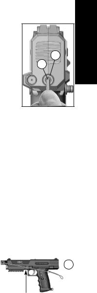
PROBLEM: Air/CO2 is leaking out of the gas vent hole (see arrow).
SOLUTION: The most common air/CO2 leak is caused by a |
|
77 |
dirty or damaged puncture seal. Check the Puncture Seal (36) |
|
|
|
|
|
for dirt or damage (see Puncture Valve Disassembly on |
|
|
page 16). |
|
|
PROBLEM: Magazine will not feed paintballs correctly. SOLUTION: Try using fresh paintballs
SOLUTION: Clean the Magazine with a damp towel to wipe off paint, grease, and debris. Dry springs immediately, if necessary, to help prevent rusting.
PROBLEM: You pull the trigger, and the marker does not pressurize. SOLUTION: Adjust the CO2 Cap assembly (see instructions on page 18).
PROBLEM: Air/CO2 is leaking from the air/CO2 cylinder connection to the remote coil tank adapter.
SOLUTION: The most common leak occurs from a bad air/CO2 cylinder valve O-ring (see
Repairing Air/CO2 Cylinder Leaks on page 24).
E N G L I S H
19

E
N |
Problems After Disassembly/Assembly Of Your Marker |
G |
Failure to reassemble parts correctly can cause damage to parts, air/CO2 leaks, and other |
L |
problems. Always double check to be sure parts are clean, not damaged, lubricated, and |
I |
installed correctly when you disassemble/reassemble your marker. |
S |
PROBLEM: You pull the trigger and the marker does not pressurize. |
HSOLUTION: Check that the puncture pin cap (44) is installed (see Puncture Valve Disassembly on page 16).
SOLUTION: Adjust the CO2 cap (see page 18).
PROBLEM: You install a cartridge and you hear air/CO2 leaking.
SOLUTION: Check to be sure the O-rings of the long gas line and the short gas line are not damaged (see Marker Disassembly on page 14).
PROBLEM: The Regulator (#77 in illustration on previous page) vents air/CO2continuously. SOLUTION: Adjust the Pressure Relief Valve (see page 19).
SOLUTION: Check the Regulator Pin (68) for dirt, damage, or if it is not inserted into the Regulator Piston (71) properly. Clean, inspect, and replace if damaged.
NOTE: When assembling, be sure the Regulator Pin seats into the Regulator Piston (see
Regulator Disassembly on page 17).
PROBLEM: You pull the trigger back and it binds and will not release.
SOLUTION: Check the Firing Pin (51) for misalignment. Disassemble the Firing Valve and make sure the Firing Pin is pushed in flush with the Firing Valve Body during assembly (see
Firing Valve Disassembly on page 15).
PROBLEM: There is air/CO2 leaking out of the barrel.
SOLUTION: Check the Front Valve Spool O-ring (60) for dirt or damage (see Air Valve Disassembly on page 16).
PROBLEM: When the trigger is pulled slowly, a short leaking sound is normal. The leak continues without the gun firing.
SOLUTION: Check the Valve Spool rear O-ring (61) and the Air Valve End Cap O-ring (61) for dirt or damage (see Air Valve Disassembly diagram on page 16).
PROBLEM: The trigger will not move at all when trying to fire.
SOLUTION: Check the trigger safety (22) to be sure it is not installed backwards. The red O-ring (32) should be on the left side of the marker (PUSH SAFE is embossed on this side), and the black O-ring (31) on the right side of the marker (PUSH FIRE is embossed on this side) (see Marker Disassembly on page 14).
PROBLEM: You fire the marker but no paintballs are fired.
SOLUTION: If the Front Bolt (54) sticks in the forward position, paintballs will not load. Check the Ball Latch (24) to be sure it is not installed backwards (see Marker Disassembly on page 14).
SOLUTION: If the Front Bolt (54) is installed correctly and does not return completely, the paintballs will not load. Check the Barrel Adapter (25) and the Air Valve Assembly (23) for dirt or damage (see Marker Disassembly on page 14).
NOTE: If a problem still exists, contact Tippmann Service Department at 1-800-533-4831 or see your local paintball dealer.
20
Remote Line Adapter (optional equipment)
NOTE: The following includes instructions for installation, turning on, and turning off the air/ CO2 cylinder of the Tippmann H-01 Remote Line. If your remote line is not this Tippmann model, follow the instructions provided with your remote line for installation, turning on, and turning off the remote air/CO2 cylinder.
Connecting, Disconnecting, and Removing a Remote Air/CO2 Cylinder
1.Eye protection designed for paintball use must be worn by the user and any person within range. Put trigger safety in Safe mode (see page 6). Install the barrel blocking device (see page 4). Remove and unload the Magazine (go to page 9 and follow
Magazine Removal, Loading, and Unloading instructions).
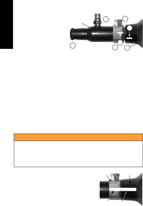
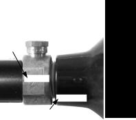
2.Pull and hold the Remote Coil fitting Locking Ring (A) down to connect or remove the Remote Coil fitting (B).
3. To connect to the marker, with the Locking Ring (A) held down, push the |
|
|
B. |
|||||||||
coil fitting (B) up onto the nipple (C) and release the locking ring up to |
|
|
|
|
|
|||||||
lock (D). Pull down on the Remote Coil fitting (E) to be sure it is locked |
|
H. |
||||||||||
properly. |
|
|
|
|
|
|
|
|
||||
|
|
|
|
|
|
|
|
|
|
|
|
|
4. Before attaching the air/CO2 cylinder to the Remote Line, markers with |
|
|
|
|
|
|||||||
a Remote Line Adaptor must first have an empty 12 gram CO2 cartridge |
|
|
|
|
|
|||||||
installed to operate properly. Turn off the Remote Line air/CO2 flow control |
|
|
|
|
|
|||||||
valve (F) by turning the flow control (G) counterclockwise outward until it |
|
|
|
|
|
|||||||
stops (see illustration at right). Install a 12 gram CO2 cartridge |
|
|
|
|
|
|
|
|
|
|
|
|
by following the CO2 Cartridge Installation instructions on |
C. |
D. |
|
|
|
|||||||
page 8. Empty the cartridge of all CO2 by following steps 1-6 in |
|
|
|
|
|
|||||||
|
|
|
|
|
||||||||
leaving the empty cartridge installed in the marker.on page 11, |
|
|
|
|
|
|
|
|
|
|
|
|
|
|
|
|
|
|
|
|
|
|
|
|
|
|
|
|
|
|
|
|
|
|
|
|
|
|
5. Install the air/CO2 cylinder. First mark the cylinder and cylinder |
|
|
|
|
|
|
|
|
|
|
|
|
|
|
|
|
|
|
|
|
|
|
|
|
|
valve if necessary (see Air/CO2 Cylinder Warnings and |
|
|
|
|
|
|
|
|
|
|
|
|
|
|
|
|
|
|
|
B. |
|
|
|
||
|
|
|
|
|
|
|
|
|
|
|||
Safety Tips on pages 22-24). Lubricate the cylinder valve |
|
|
A. |
E. |
||||||||
O-ring with a little marker grease, then insert the cylinder valve |
|
|
|
|
|
|
|
|
|
|
|
|
end into the Air Supply Adapter (ASA) of the Remote Line. Twist |
|
|
|
|
|
|
|
|
|
|
|
|
the cylinder clockwise into the ASA (H) until it stops. Your marker is |
|
|
|
|
|
|
|
|
|
|||
ready to fire once you: |
|
|
|
|
G. |
|
F. |
|
|
|
||
• turn on the flow control (G) clockwise all the way in (J), |
|
|
|
|
|
|
|
|
|
|
|
|
• remove the barrel blocking device, and |
|
|
|
|
|
|
|
|
|
|
|
|
|
|
|
|
|
|
|
|
|
|
|
|
|
• switch the trigger safety from Safe mode to Fire mode. |
|
|
|
|
|
|
|
|
|
|
|
|
|
|
|
|
G. |
|
J. |
|
|
|
|||
To turn off the air/CO2 supply, turn the flow control (G) completely |
|
|
|
|
|
|
H. |
|||||
clockwise out (F). To turn on air supply, turn flow control |
|
|
|
|
|
|
|
|
|
|
|
|
|
|
|
|
|
|
|
|
|
|
|
|
|
counterclockwise completely in (J). |
|
|
|
|
|
|
|
|
|
|
|
|
NOTE: If the air/CO2cylinder is full, and you do not hear the marker pressurize, the Pin Valve could be too short or the Pin Valve Seal is damaged. You will need to remove the remote air/CO2 cylinder and take it to a “C5” Certified Airsmith for repair.
6.Air/CO2 Cylinder Removal — You must first read the Air/CO2 Cylinder Warnings and Safety Tips on pages 22–24 before beginning the cylinder removal process in
step 7.
E N G L I S H
21
E
N |
7. Refer to the illustration at |
|
|
|
|
|
|
|
|
|
Remote Coil Air |
|
|
|
|
|
|
STOP |
|||
G |
right. Whenever you turn the |
H. |
5. |
|
||||||
|
||||||||||
air/CO2 cylinder (2) during |
Supply Adapter |
|
|
|
|
|
|
|
||
|
|
|
|
|
|
|
||||
L |
|
|
|
|
|
|
|
|
|
|
removal, watch the mark (4) |
|
|
|
|
|
|
4. |
|||
|
|
|
|
|
|
|||||
I |
on the cylinder and the mark |
|
|
|
|
|
|
|
|
|
S |
(3) on the cylinder valve to be |
|
|
|
|
|
|
|
|
|
H |
sure that they rotate together. |
|
|
|
|
|
|
|
|
|
If you see the marks begin |
|
|
|
|
|
3. |
|
|
|
|
|
to separate (5), STOP! and |
G. |
|
|
|
|
|
|
|
|
|
1. |
2. |
|
|||||||
|
take your marker to a qualified |
|
|
|
||||||
|
professional, such as a “C5” certified airsmith. |
|
|
|
|
|
|
|
||
8.Turn the cylinder approximately 3/4 turn counterclockwise. This allows the air supply pin valve to close so that no air will enter the marker. Point the marker in a safe direction and discharge the remaining gas in the marker by pulling the trigger until the marker stops firing. If your marker continues to fire, the cylinder pin valve has not closed yet (the cylinder pin valve could be too long, because of the variances in cylinder pin valve parts, each cylinder varies slightly on exactly how far it should be turned) and you will have to turn the cylinder counterclockwise a little further and repeat this step until the marker does not fire, then remove the cylinder. NOTE: If during this step, you turned the cylinder and it began to leak before you pulled the trigger, the cylinder O-ring should be checked for damage before reassembly (see Repairing Air/CO2 Cylinder Leaks on page 24).
9.After the air/CO2 cylinder is removed, point and fire the marker in a safe direction until stored air is completely discharged.
NOTE: Before storing or disassembling be sure to follow Magazine Removal, Loading, and Unloading instructions on page 9 and CO2 Cartridge Removal instructions on page 10. Put the trigger safety in Safe mode (see page 6) and install the barrel blocking device (see page 4).
Air/CO2 Cylinder Warnings
 WARNING
The brass or nickel plated cylinder valve (#1) is intended to be permanently attached to the air or CO2 cylinder (2). An air or CO2 cylinder can fly off with enough force to cause serious injury or death if the cylinder (2) unscrews from a cylinder valve (1).
Refer to the figure at right. There have been reported incidents |
1 |
|
2 |
caused by players unknowingly unscrewing the cylinder (2) |
|
|
|
from the cylinder valve (1). This occurs when the player thinks |
|
|
|
the entire valve-cylinder assembly is being unscrewed from |
|
|
|
the air/CO2 adaptor of the paintball marker, when in fact he or |
|
|
|
she is unscrewing the cylinder from the cylinder valve. |
|
|
|
To avoid this danger, it is recommended (if your cylinder is not |
|
3 |
4 |
already marked) that you use paint or nail polish to place a |
|
|
|
|
|
|
mark (3) on the cylinder valve, and place another mark (4) on the cylinder, in line with the #3 mark as shown.
22
Whenever you turn the cylinder during removal, watch the |
|
|
|
marks on the cylinder and the cylinder valve to be sure |
3 |
that they rotate together. If at any time these marks start to |
|
separate as shown in the figure at right, the cylinder is starting |
|
to unscrew from the cylinder valve and you must STOP and |
|
take the entire unit to a “C5” certified airsmith for safe removal |
|
and/or repair. |
4 |
NOTE: The cylinder valve should unscrew from the paintball |
|
marker in about 3 or 4 full turns. If you finish the 4th full turn |
|
and the cylinder valve is not unscrewed from the paintball marker, STOP! Take the entire unit to a “C5” certified airsmith for safe removal and/or repair.
Locate a “C5” Certified Airsmith at www.paintball-pti.com/search.asp.
Whether you have a new or used refillable air/CO2 cylinder, you are at risk if any of the following has occurred:
•The valve unit was replaced or altered after purchase.
•An anti-siphon device was installed.
•The valve unit was removed from the cylinder for any reason.
•Any modification was done to the refillable air/CO2 cylinder.
If any of these conditions has occurred, take your air/CO2 cylinder to a “C5” Certified Airsmith for inspection or contact the cylinder manufacturer.
E N G L I S H
Air/CO2 Cylinder Safety Tips
SAFETY TIPS to ensure that your air/CO2 cylinder is safe for play:
•Improper use, filling, storage, or disposal of air/CO2 cylinder may result in property damage, serious personal injury or death.
•Make sure that any maintenance or modification to any air/CO2 cylinder is done by a qualified professional, such as a “C5” certified airsmith.
•The use of anti-siphon devices is not recommended. However, if one is already installed on your air/CO2 cylinder or is desired, it is critical that your cylinder be checked by, or the device installed by, a qualified professional.
•All air/CO2 cylinders must be filled only by properly trained personnel.
•Cylinder valves must be installed only by properly trained personnel.
•Do not overfill a cylinder! Never exceed the air/CO2 cylinder’s capacity.
•Do not expose pressurized air/CO2 cylinder to temperatures exceeding 130 degrees Fahrenheit (55 degrees Celsius).
•Do not use caustic cleaners or strippers on the air/CO2 cylinder or cylinder valve and do not expose to corrosive materials.
•Do not modify the air/CO2 cylinder in any way. Never try to disassemble the cylinder valve from the air/CO2 cylinder.
•Any air/CO2 cylinder that has been exposed to fire or heated to a temperature of 250 degrees Fahrenheit (121 degrees Celsius) or more must be destroyed by properly trained personnel.
23
E |
• |
Use appropriate gas for your cylinder. Only use CO2 in a CO2 cylinder and only use |
N |
||
G |
|
compressed air in a compressed air cylinder. |
L |
• |
Keep all cylinders out of the reach of children. |
I |
• |
The Air or CO2 cylinder should be inspected and hydrostatically retested at least |
S |
|
every 5 years by a DOT licensed agency. |
H |
• |
Keep exposed skin away from escaping gas when installing or removing air/CO2, or |
|
|
if the marker or air/CO2 is leaking. Compressed air and CO2 gasses are very cold, |
|
|
and can cause frostbite under certain conditions. |
|
|
NOTE: Locate a “C5” certified airsmith at www.paintball-pti.com/search.asp
Repairing Air/CO2 Cylinder Leaks
The most common leak occurs from a bad air/CO2 valve O-ring. To replace a valve O-ring you must first remove the bad O-ring and then install a new one. This O-ring is located on the tip of your air/CO2 valve. The best valve O-rings are made of urethane. Urethane O-rings are not affected by high air/CO2 pressures. These may be purchased from Tippmann or your local paintball dealer.
NOTE: If a new air/CO2 valve O-ring does not resolve an air/CO2 leak, do not attempt to repair the air/CO2 cylinder. Contact Tippmann Sports, LLC, your local paintball dealer, or a “C5” Certified Airsmith.
Storage
Before storage, follow the Magazine Removal, Loading, and Unloading instructions on page 9 and CO2 Cartridge Removal instructions on page 10 (on page 21 for markers with a Remote Line Adapter installed). Do not store a marker with any of the following installed:
•12 gram air/CO2 supply cartridge (punctured or unpunctured)
•an air/CO2 cylinder
•Magazine
Store the Magazine empty, with the Ball Carrier in its topmost position.
Put the trigger safety in Safe mode (see page 6) and install the barrel blocking device (see page 4). You should store your marker in a dry area. Before storing your marker, make sure that the marker is cleaned and lubricated (see Cleaning & Maintenance on page 12) so that it does not rust.
When removing your marker out of storage, make sure that the trigger safety is in Safe mode (see page 6) and the barrel blocking device is installed (see page 4).
24

Specifications
Model........................................................................................................... |
|
TIPPMANN® TPX |
Caliber................................................................................................................................ |
|
.68 |
Action................................................................... |
Semi-Automatic (Open Bolt Blow Forward) |
|
Power/Propellant................................................................. |
|
compressed air, nitrogen, or CO2 |
Cartridge ............................................................................................................ |
|
12 gram CO2 |
Shots per 12 gram CO2 cartridge................................................................. |
|
approximately 19 |
Paintball Feed ............................................................................ |
|
TPX Magazine (spring feed) |
Magazine Capacity................................................................................................. |
|
7 Paintballs |
Cycle Rate...................................................................... |
|
1 trigger pull = 1 shot (6 per second) |
Standard Barrel Length ............................................................................... |
|
6.25” / 15.875 cm |
Overall Length (with standard barrel)............................................................. |
|
10.8” / 27.43 cm |
Weight (without 12 gram CO2 cartridge or paintballs). |
................................1.81 lbs. / .821 kg |
|
Effective Range............................................................................................... |
|
150+ ft. / 46+ m |
Velocity.................................................................................................................... |
|
Adjustable |
Always measure your marker’s velocity before playing paintball and never shoot at velocities in excess of 300 feet/91.44 meters per second (see Velocity Adjustment instructions on page 10).
E N G L I S H
25
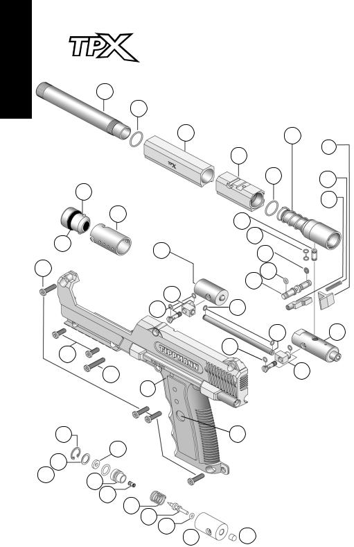
E
N
G
L
I
S 27
H
15
14
18
10
8
9
by TIPPMANN®
Parts Diagram
29
26 |
23 |
|
25 |
|
28 |
|
20 |
|
30 |
7 |
31 |
|
32 |
|
22 |
12 |
|
30 |
30 |
|
19 |
|
30 |
12
2
PUNCTURE VALVE
ASSEMBLY PARTS
34 |
17 |
36
35
37 
38
39
40
41
42
43 44
3
13
4
21
26

 WARNING
Do not disassemble this marker while it is pressurized. Do not pressurize a partially assembled marker.
11 |
|
|
|
|
|
45 |
|
|
1 |
46 |
47 |
|
|
||
|
|
|
|
16 |
|
|
48 |
24 |
|
50 |
49 |
|
|
|
|
|
|
|
51 |
33 |
|
|
|
56
52 |
53 |
|
|
78 |
54 |
55 |
|
|
56 |
57 |
|
|
|
||
|
|
|
58 |
66
68
67
69
Rev. 06/09/10
Tippmann® Service Department
1-800-533-4831
www.tippmann.com
60
61 62
59
63
64
65
70

 74 76 72 71

75
73
77
E N G L I S H
27
 Loading...