


-BACK COVER - BLANKp |
|
TIPPMANN® |
TIPPMANN® |
|
|
CUSTOMTM E-TRIGGERTM |
A-5TM E-GRIPTM |
|
|
KIT PN.205002 |
KIT PN. 02-EG |
|
|
Fits: 98 CustomTM markers with |
Fits: |
|
|
serial# over |
A-5TM |
|
|
880,000 and all |
markers |
|
|
98 Custom ProTM |
|
|
|
markers. |
|
|
|
INSTALLATION |
INSTALLATION |
|
|
AND OPERATING |
AND OPERATING |
|
|
INSTRUCTIONS |
INSTRUCTIONS |
|
|
|
|
|
|
TIPPMANN® |
TIPPMANN® |
|
|
CUSTOMTM DÉTENTE E TM |
A-5TM POIGNÉE - E TM |
|
|
KIT PN.205002 |
Kit PN. 02-EG |
|
|
Convient: les marqueurs de |
Convient: |
|
|
98 CustomTM avec serial# plus |
A-5TM |
|
|
de 880,000 |
marqueurs |
|
|
et tous les |
|
|
|
marqueurs de |
|
|
|
98 Custom ProTM. |
|
|
|
INSTRUCTIONS |
INSTRUCTIONS |
|
|
D'INSTALLATION |
D'INSTALLATION |
|
|
ET D'OPÉRATION |
ET D'OPÉRATION |
|
|
|
|
|
|
TIPPMANN® |
TIPPMANN® |
|
|
CUSTOMTM E-TRIGGERTM |
A-5TM E-GRIPTM |
|
|
ESTUCHE PN.205002 |
ESTUCHE PN.02-EG |
|
|
Puede Ser Usado con: marcadores |
Se puede |
|
|
98 CustomTM con |
usar con |
|
|
serial# mayor a |
marcadores: |
|
|
880,000 y todos |
A-5TM |
|
|
los marcadores |
|
|
|
98 Custom ProTM. |
|
|
|
INSTALACIÓN E |
INSTALACIÓN E |
|
|
INSTRUCCIONES |
INSTRUCCIONES |
|
|
DE MANEJO |
DE MANEJO |
|
|
|
Form# TP04206 Rev 02-08 |
|
|
|
|
E N G L I S H
F R A N
Ç
A
I
S
E S P A
Ñ
O L
|
|
|
|
|
|
TIPPMANN® |
|
|
||
|
|
|
|
|
|
|
|
|||
E |
|
|
|
2955 ADAMS CENTER ROAD, FORT WAYNE, IN 46803 |
||||||
|
|
|
260/749-6022 • 800/533-4831 • FAX: 260/749-6619 |
|||||||
|
|
|
|
|
INTERNET: www.tippmann.com |
|
|
|||
N |
|
Please take time to read through and follow these Installation and Operating |
||||||||
G |
|
Instructions thoroughly and become familiar with the Tippmann® CUSTOMTM |
||||||||
|
E-TRIGGERTM or A-5TM E-GRIPTM parts, operation, and safety precautions before |
|||||||||
L |
|
you attempt to load or fire this marker. If you have a missing or broken |
||||||||
|
part or need assistance, please contact Tippmann® Consumer Relations |
|||||||||
I |
|
at 1-800-533-4831 for fast friendly service. |
|
|
||||||
S |
|
|
|
|
|
TABLE OF CONTENTS |
|
|
||
H |
|
CUSTOMTM |
E-TRIGGERTM KIT PN.205002: Installation .......... |
1-E CustomTM |
||||||
|
A-5TM E-GRIPTM KIT PN. 02-EG: Installation |
....................................... |
|
4-E A-5TM |
||||||
|
|
Operating Instructions (CustomTM or A-5TM) |
............................................... |
|
7-E |
|||||
|
|
|
|
|
|
|
|
|
|
|
|
|
|
|
|
|
TIPPMANN® |
|
|
||
|
|
|
|
|
|
|
|
|||
F |
|
|
|
2955 ADAMS CENTER ROAD, FORT WAYNE, IN 46803 |
||||||
|
|
|
260/749-6022 • 800/533-4831 • FAX: 260/749-6619 |
|
|
|||||
R |
|
|
|
|
INTERNET: www.tippmann.com |
|
|
|||
|
S’il vous plaît, prenez le temps de lire entièrement ces Instructions |
|||||||||
A |
|
D'installation et D'opération et familiarisez – vous avec les parties, l’ |
||||||||
N |
|
opération, et les précautions de sécurité de Tippmann ® CUSTOMTM |
||||||||
|
DÉTENTE E TM ou A-5TM Poignée - ETM |
avant de charger et de tirer ce |
||||||||
Ç |
|
marqueur. |
Si vous avez quelque chose manquante ou quelque chose |
|||||||
A |
|
cassée ou si vous avez besoin d’ assistance, veuillez contacter Tippmann ® |
||||||||
|
Consumer Relations à 1-800-533–4831 pour l’assistance amicale et vite. |
|||||||||
I |
|
CUSTOM |
|
DÉTENTE E |
|
TABLE DES MATIÈRES |
1-F Custom |
|||
S |
|
TM |
TM |
KIT PN.205002: D'installation ........ |
||||||
|
|
|
|
|
|
TM |
||||
|
A-5TM Poignée - ETM Kit PN. 02-EG: D'installation............................. |
4-F A-5TM |
||||||||
|
|
Instructions D'opération (Custom ou A-5 |
TM |
) ............................................. |
7-F |
|||||
|
|
|
|
|
|
TM |
|
|
|
|
|
|
|
|
|
|
|
|
|
||
|
|
|
|
|
|
TIPPMANN® |
|
|
||
E |
|
|
|
2955 ADAMS CENTER ROAD • FORT WAYNE, IN 46803 |
||||||
|
|
|
260/749-6022 • 800/533-4831 • FAX: 260/749-6619 |
|||||||
S |
|
|
|
|
|
INTERNET: www.tippmann.com |
|
|
||
|
Antes de cargar o disparar este marcador por favor tome tiempo para leer |
|||||||||
P |
|
completamente estas Instrucciones de Instalaciónes y De Manejo y empezar a |
||||||||
A |
|
familiarizarse con las partes, operación y todas las precauciones de seguridad |
||||||||
|
del Tippmann® CUSTOMTM E-GATILLOTM o A-5TM E-GRIPTM . Si alguna de sus |
|||||||||
Ñ |
|
partes no se encuentra, o esta defectuosa y necesita asistencia, por favor |
||||||||
O |
|
comuníquese con el departamento de Servicio al Cliente de Tippmann® al |
||||||||
|
teléfono 1-800-533-4831 en donde le daremos un servicio oportuno y amable. |
|||||||||
L |
|
|
|
|
TABLA DE CONTENIDO |
|
|
|||
|
|
CUSTOMTM E-TRIGGERTM ESTUCHE PN.205002: Instalación ... |
1-S CustomTM |
|||||||
|
|
A-5TM E-GRIPTM ESTUCHE PN.02-EG: Instalación ........................ |
4-S A-5TM |
|||||||
|
|
Instrucciones De Manejo (CustomTM o A-5TM) ........................................... |
7-S |
|||||||
|
|
|
|
|
|
|
|
|
|
|
98 CUSTOMTM INSTALLATION INSTRUCTIONS
TIPPMANN® CUSTOMTM E-TRIGGERTM KIT
Fits: 98 CustomTM markers with Serial# over 880,000 and all 98 Custom ProTM markers
CUSTOMT M E-TRIGGERTM KIT PN.205002 INCLUDES:
1 |
- Sear Tripper Assembly PN.TA99007 |
||
1 |
- New Sear PN. TA01135 1 - New Sear Spring PN. 02-88 |
||
1 |
- Armature Pin PN. 98-91 1 - Magnet PN. TA05014 |
||
|
|
|
|
WARNING
EYE PROTECTION DESIGNED FOR PAINTBALL USE MUST BE WORN AT ALL TIMES WHEN HANDLING THIS MARKER BY THE USER AND ANY PERSON WITHIN RANGE. DO NOT DISASSEMBLE THIS MARKER WHILE IT IS PRESSURIZED WITH AIR. REMOVE AIR SUPPLY CYLINDER OR CARTRIDGE BEFORE DOING ANY DISASSEMBLY. DISASSEMBLING THE RECEIVER WHILE UNDER AIR PRESSURE CAN CAUSE PERSONAL INJURY & / OR DAMAGE TO THE MARKER. DO NOT OPERATE THIS MARKER WITH PARTS MISSING OR DAMAGED. IF DURING THE COURSE OF THIS INSTALLATION, A PART IS LOST OR FOUND TO BE DAMAGED, OBTAIN A REPLACEMENT PART BEFORE CONTINUING REASSEMBLY.
READ EACH STEP COMPLETELY BEFORE PERFORMING STEP. Keep these instructions with your owner’s manual.
STEP 1: Prepare marker for safe disassembly before beginning disassembly.
Eye protection designed for paintball use must be worn by the user and any person within range.
1) Unload your marker: first remove the hopper. Then, point your marker in a safe direction and fire several times to be sure there are no balls left in the feeder or lodged in the chamber.
2) Remove air source: To remove a charged air cylinder, turn the
cylinder approximately 3/4 of a turn counterclockwise  or out. This allows the tank pin valve to close so that no air will enter the marker. Point the marker in a safe direction and fire the remaining air in the marker by pulling the trigger until the marker stops firing (This may take 4-5 shots).
• If your marker keeps firing after you have turned the tank 3/4 of a turn, the tank pin valve has not closed yet and you may have to turn the tank
counterclockwise  a little further.
• If you turn the tank 3/4 of a turn and it begins to leak before you pull the trigger you have turned it too far and may have damaged the tank o-ring.
3) After air tank is removed, point & fire the marker in a safe direction until stored air is completely discharged.
4) Put marker in the uncocked position: pull and hold the bolt cocking handle back, then pull the trigger and slowly release the handle forward to un-cock the marker.
1-E CustomTM (continued on page 2-E CustomTM)
E N G L I S H

|
|
(98 CUSTOMTM INSTALLATION INSTRUCTIONS continued from page 1-E CustomTM) |
|||
|
|
9 VOLT BATTERY REPLACEMENT |
|
||
|
|
1) Prepare Your Marker For Safe Disassembly: Follow the |
|
||
E instructions in STEP 1. |
|||||
N |
|
2) Remove Battery Clip / Battery From Marker: Remove left grip |
|||
|
|
2 bolts . Carefully work the battery out of the receiver cutout bringing |
|||
G non-connected end out first. As you remove battery from receiver, do not |
|||||
L |
|
pull wires off of internal components. Carefully remove old battery from |
|||
I |
|
battery clip connector. |
|||
|
3) Install the New Battery: Follow instructions in: STEP 4: 6), 7), & 8). |
||||
S |
|
|
|
|
|
|
STEP 2: Prepare Marker for kit installation. |
|
|||
HSet up a table with plenty of space to work. You will need two allen
wrenches ( ) 1/8" and 5/32", hammer, punch, and a 9 volt battery. NOTE: Carefully hand start threaded parts, do not over tighten and strip threads.
Disassemble the marker: With Air Source removed & marker in the uncocked position
as per STEP 1;
1) Remove
the barrel  ,
,
twist counterclockwise.
2) Remove left side receiver
grip |
two bolts . |
|
3) Remove tank adapter |
2 bolts . |
|
4) Loosen all 6 receiver bolts / |
||
holding marker together with 1/8" Allen |
||
wrench. Note: Front Grip |
comes off - |
|
at reassembly, longest bolt |
goes in front grip. |
|
5) Carefully lift left receiver half  off marker.
6) Remove rectangular knockout plate  from left receiver half
  for battery insertion.
Place left receiver half  inside up with knockout plate
  flush on a flat surface.
Then with a hammer and punch, start in one
corner of the plate  and carefully tap it loose by working your way around the plate edge....
until it is removed.
7) Remove trigger  & trigger spring
  .
.
Remove trigger slider  , slider spring
  and 2 slider pins
  from trigger.
8) Remove old sear and sear spring  from right receiver. If black dowel pin
  comes out, reinsert it. TIME SAVER: It is Not necessary to remove additional
parts to install this kit.
(continued on page 3-E CustomTM)
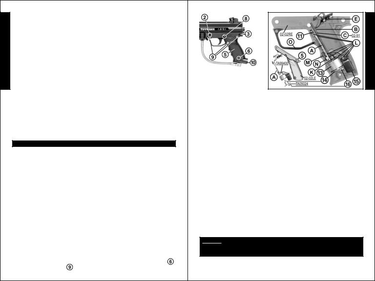
(98 CUSTOMTM INSTALLATION INSTRUCTIONS continued from page 2-E CustomTM)
9) Install trigger  and trigger spring
  into the right receiver half
  .
.
10) Install new sear  and new sear spring
  into right receiver half
  .
.
11) Install trigger guard  .
.
STEP 3: Install Sear Tripper Assembly, Magnet & Armature Pin
Do not operate sear tripper assembly uninstalled as solenoid /armature may pinch you.
1) Place solenoid  / armature
  into position in right receiver
  .
.
2) Insert Magnet  into slot below armature.
3) Carefully align and insert computer board  into slot.
4) Place trigger switch  on
on
2 pins of right receiver half.
5) Insert capacitor in slot.
6) Route wires in cutout areas |
to lay |
|
flat under armature pin |
and battery (and not |
|
be pinched when receiver halves are reassembled.
Visually inspect internal wires for disconnected wire end(s)  or damage.
7) Insert armature pin  into slots so it moves freely.
8) Double check that all parts are in place as shown.
STEP 4: Reassemble Receiver Halves
1) Double check that all other parts: Front Sight, Front Site Pin, Front Sight Spring, Ball Latch, Front Bolt*, Linkage Arm, Rear Bolt*(+Rear Bolt Insert on non-A.C.T. markers), Drive Spring* & Guide Pin*, Buffer O-ring, End Cap, Rear Sight and 2 Tank Adapter Nuts {and for markers with Anti-
Chop Technology: the Spring Cup*, Upper Spring (long)*, Spring Pin*, Upper Spring (short)*, and Linkarm Pins*(2); are in place /(*=oiled)}. Refer to the marker owner's manual for details if needed.
2) Place battery connector  through left receiver half make sure the magnet fits into left receiver half slot so it does not break and wires are not pinched as you place left half on right half so the halves fit flush.
3) Insert 5 short receiver bolts  . Insert front grip
 and insert long receiver bolt
  to hold grip. For ease of installation tighten the bolt over the trigger first, then tighten 5 remaining bolts.
4) Attach adapter  with 2 bolts
  .
.
5) Install barrel  .
.
6) Attach 9v battery to battery connector and be sure
wires lay flat inside the cutout area of receiver (see STEP 3:).
7) Carefully tilt and insert battery (wire attached end first |
) |
|
into receiver. 8) Install left receiver grip |
with 2 bolts |
. |
Installation is complete, continue on page 7-E Operating Instructions.
3-E CustomTM |
(continued on page 7-E) |
E N G L I S H

|
|
A-5TM INSTALLATION INSTRUCTIONS |
E |
|
TIPPMANN® A-5TM E-GRIPTM KIT PN. 02-EG |
|
Fits: A-5TM Markers |
|
N |
|
|
KIT PN. 02-EG INCLUDES: |
||
G |
|
(1) 1 - E-GRIPTM Lower Receiver Component |
|
||
L |
|
WARNING |
I |
|
EYE PROTECTION DESIGNED FOR PAINTBALL USE MUST BE WORN AT |
S |
|
ALL TIMES WHEN HANDLING THIS MARKER BY THE USER AND ANY |
|
PERSON WITHIN RANGE. DO NOT DISASSEMBLE THIS MARKER WHILE |
|
H |
|
IT IS PRESSURIZED WITH AIR. REMOVE AIR SUPPLY CYLINDER OR |
|
|
CARTRIDGE BEFORE DOING ANY DISASSEMBLY. DISASSEMBLING THE |
|
|
RECEIVER WHILE UNDER AIR PRESSURE WILL CAUSE PERSONAL |
|
|
|
|
|
INJURY & /OR DAMAGE TO THE MARKER. DO NOT OPERATE THIS |
|
|
MARKER WITH PARTS MISSING OR DAMAGED. IF DURING THE COURSE |
|
|
OF THIS INSTALLATION, A PART IS LOST OR FOUND TO BE DAMAGED, |
|
|
OBTAIN A REPLACEMENT PART BEFORE CONTINUING REASSEMBLY. |
|
|
READ EACH STEP COMPLETELY BEFORE PERFORMING STEP |
|
|
|
|
|
STEP 1: Prepare Marker for SAFE Disassembly before |
|
|
beginning disassembly. |
|
|
|
Eye protection designed for paintball use must be worn by the user and any person within range.
1) Unload your marker: first remove the hopper. Then, point your marker in a safe direction and fire several times to be sure there are no balls left in the feeder or lodged in the chamber.
2) Remove air source: To remove a charged air cylinder, turn the cylinder
approximately 3/4 of a turn counterclockwise  or out. This allows the tank pin valve to close so that no air will enter the marker. Point the marker in a safe direction and fire the remaining air in the marker by pulling the trigger until the marker stops firing. (This may take 4-5 shots)
• If your marker keeps firing after you have turned the tank 3/4 of a turn, the tank pin valve has not closed yet and you may have to turn the tank
counterclockwise  a little further.
• If you turn the tank 3/4 of a turn and it begins to leak before you pull the trigger you have turned it too far and may have damaged the tank o-ring.
3) After air tank is removed, point & fire the marker in a safe direction until stored air is completely discharged.
4) Put marker in the uncocked position: pull and hold the bolt cocking handle back, then pull the trigger and slowly release the handle forward to un-cock the marker.
4-E A-5TM |
(continued on page 5-E A-5TM) |
(A-5TM INSTALLATION INSTRUCTIONS continued from page 4-E A-5TM)
STEP 2: Prepare Marker for installation.
Set up a table with plenty of space to work. You Will Need: A ( ) 1/8" allen wrench and a 9 volt battery. NOTE: Carefully hand start threaded parts, do not over tighten and strip threads.
Dissassemble the marker: With Air Source removed & marker in the uncocked position 
as per STEP 1: 1) Detach the lower receiver  : Remove 2 lower receiver push pins
( & |
) to detach |
. |
from upper receiver |
||
2) Detach Tank |
|
|
Adapter |
from lower |
|
receiver. Remove receiver bolt  from lower receiver.
STEP 3: Battery Installation / Replacement
E-gripTM lower receiver must be removed to install / replace battery.
1) To do so, you must complete the instructions “STEP 1” (unload your marker / remove air source / discharge stored air / uncock marker) before further disassembly. – EXAMPLE: If you fail to remove the air source before removing lower receiver, the marker will fire uncontrollably - possibly resulting in personal injury and damage to the marker).
2) Remove lower receiver as outlined in “STEP 2” (it is not necessary to remove tank adapter bolt  to replace battery).
3) Remove trigger assembly  from lower
receiver. (NOTE: It is not necessary to disassemble |
|
||
the trigger assembly to install battery. |
|
||
Do not replace sear spring with |
|
||
spring from old trigger assembly, |
|
||
tensions are specifically designed |
|
||
for E-GRIPTM and it will not operate |
|
||
properly if you do). To remove the |
|
||
trigger assembly, push the safety |
|
||
out of the left |
side of the lower |
|
|
receiver and carefully lift the trigger |
|
||
assembly out, keeping it intact . |
(4) |
||
NOTE: It is not necessary to |
|||
|
|||
disassemble the lower receiver any |
|
||
further to install/replace the battery.
5-E A-5 |
TM |
(continued on page 6-E A-5TM) |
|
E N G L I S H

|
(A-5TM INSTALLATION INSTRUCTIONS continued from page 5-E A-5TM) |
|
|
4) Notice how |
|
|
|
|
|
battery wires from |
|
E inside lower receiver |
|
|
|
are in slot |
|
N beside top of |
|
|
G armature pin |
|
|
L |
and the position |
. |
I |
of the armature pin |
|
To replace the battery, remove |
||
S old battery from inside the E-GripTM lower receiver. Do not jerk it out by the |
||
Hwires, carefully take it out. If you turn the receiver upside down the armature pin  may come out, this is ok, just be sure to replace it. Carefully remove battery clip
  from old battery.
5) Carefully attach battery clip  to new battery. NOTE: battery terminals only fit one way in clip.
6) Make sure battery wires coming out of lower receiver are in slot  beside the armature pin
  .
.
7) Make sure armature pin is properly positioned  in lower receiver and slides freely up and down.
8) Insert attached battery into lower receiver
bottom first  with clip wires facing the back of the receiver
  and to the right
  .
.
NOTE: Make sure battery wires are not sitting on shelf where the trigger assembly will rest.
9) Insert Trigger Assembly  and line up safety holes
insert the safety from the left  to hold the trigger assembly in place.
10) Visually inspect E-GRIPTM lower receiver, a top view with the
trigger assembly  and battery installed should look like this.
Check that the trigger
assembly is intact |
with |
|
|
no gaps |
; and the safety is in the “SAFE” |
. |
|
(pushed to the right and red not showing) position |
|||
11) Attach Lower to Upper Receiver Align the E-GripTM lower receiver
front push pin hole  with upper receiver hole
  then gently rock rear of grip to align upper & lower push pin hole
  . With holes aligned, insert two lower receiver push pins
  and
and  to attach.
12) Attach Tank Adapter to E-GripTM. Remove receiver bolt  from lower receiver. Slide tank adapter
  into lower receiver and align holes;
Insert receiver bolt  and tighten.
Installation is complete, continue on page 7-E - OPERATING
INSTRUCTIONS.
6-E A-5TM
OPERATING INSTRUCTIONS
With the kit installation complete, read and follow these supplemental operating |
E |
||||||
instructions to the owner's manualFOR TIPPMANN A-5TM WITH E-GRIPTM , |
|||||||
98 CUSTOMTM OR 98 CUSTOM PROTM WITH E-TRIGGERTM marker with the |
N |
||||||
"EQUALIZERTM LED BOARD INSTALLED before attempting to operate this |
|||||||
marker. Keep these instructions with your marker owner's manual. Eye protectionG |
|||||||
designed for paintball use must be worn by the user and any person within range. |
L |
||||||
READ EACH STEP COMPLETELY BEFORE PERFORMING STEP: |
I |
||||||
STEP 1: Prepare the marker for safety before any programming: |
|
||||||
|
|
|
|
|
|
|
S |
|
|
WARNING |
|
|
|
|
|
|
|
|
|
|
|
H |
|
I N S TA L L T H E A I R S U P P LY A N D L O A D T H E H O P P E R W I T H |
|
||||||
|
|
||||||
PAINTBALLS ONLY AFTER YOU: |
|
|
|
|
|
||
HAVE THE BARREL SLEEVE INSTALLED; |
|
|
|
|
|
||
HAVE THE SAFETY IN THE "SAFE" POSITION; |
|
|
|
|
|
||
HAVE SUCCESSFULLY INSTALLED THE BATTERY AND |
|
|
|||||
ARE FAMILIAR WITH THE E-TRIGGERTM NORMAL OPERATION (STEP |
|
|
|||||
2: AND STEP 3:). |
|
|
|
|
|
|
|
|
|
|
|
|
|
||
STEP 2: NORMAL OPERATION: |
|
|
|
|
|
||
TOURNAMENT LOCK: Because the E-Trigger board requires a tool to |
|
||||||
turn it on and off, no tournament lock is necessary for competition paintball. |
|
||||||
1) To Turn ON the E-Trigger to normal operation - Ready To Fire: |
|
||||||
Without holding the trigger: Use a small object |
|
|
|
|
|
||
|
|
|
|
|
|||
like an allen wrench to press and hold the power |
|
|
|
|
|
||
Power |
|
|
|||||
button |
for 1/2 second and then release the |
|
|
||||
power button. The LED |
should light solid |
Button |
|
|
|||
Orange for 2 seconds, flash once (green in A-5s or |
|
|
|
|
|
||
red in 98s) and then light solid Green to show |
|
LED |
|
|
|||
normal operation - “Ready To Fire” mode. |
|
|
|
|
|
||
|
|
|
|
|
|||
• Your E-Trigger is now ready to fire in the SEMI-AUTO = 1 pull / release of the trigger fires 1 time (Factory set Default Firing Mode).
NOTE: If pressing the power button failed to turn on LED light, see troubleshooting on page 8-E.
2) To turn OFF the E-Trigger electronics. Press and hold the power button for 2 seconds as the LED turns solid Red, then release the Power Button and the LED will turn OFF. NOTE: The trigger electronics are set to shut-off automatically after a prolonged period of inactivity (120 minutes).
NOTE: The E-Trigger Low Battery Indicator feature: the “Ready To Fire” solid Green LED will turn to blinking red when the battery is low and needs replaced.
3) To select a new firing mode:
1) Turn ON the E-Trigger to normal operation (solid Green LED - Ready To Fire) as instructed in step 1) above.
2) Press / hold the power button in one time for more than 1/4 but less than 2 seconds and release the power button. Count the LED Orange
7-E (CustomTM or A-5TM) |
(continued on page 8-E) |
|
(OPERATING INSTRUCTIONS continued from page 7-E) |
|
flashes to identify your new setting, the LED light will return to solid Green - |
|
|
|
Ready To Fire - in the new firing mode. You can program your marker for |
E any one of 5 firing modes. The orange flashes = firing mode options are: |
|
N |
• 1 orange flash = SEMI-AUTO MODE – 1 pull/release of the trigger fires |
1 time (default firing mode). (This adheres to the 2005 NPPL rules). |
|
G |
• 2 orange flashes = 3 SHOT RAMPING MODE – 3 trigger pulls are |
L |
required (semi-auto) and the consecutive trigger pulls will fire 3 shots |
per pull as long as the trigger is pulled at least 5 times per second. |
|
I(This adheres to the 2005 PSP rules).
•3 orange flashes = 3 SHOT FULL AUTO MODE – 3 trigger pulls are S required (semi-auto) after which the trigger can he held to achieve full
Hauto firing. (This adheres to the 2005 NXL rules).
•4 orange flashes = AUTO RESPONSE MODE – Fires one shot for each pull or release of the trigger. If the trigger is held for more than 1/4 of a second, when the trigger is released no shot is fired.
•5 orange flashes = TURBO MODE – Fires one shot for each pull of the trigger until the time between trigger pulls is less than 1/4 of a second
at which point it will fire on each trigger pull and trigger release.
Repeat step 2) until you have the firing mode you want.
You are now ready to complete the remaining steps in the GETTING STARTED section of your owner’s manual: beginning with STEP 2: Air Supply Cylinder Installation. NOTE: If marker will not fire see page 8-E: E-Trigger - Troubleshooting (below).
E-TRIGGER – TROUBLESHOOTING
PROBLEM: The LED light does not light when you push the power button and attempt to turn ON the E-Trigger in STEP 2: NORMAL OPERATION.
1)Battery may be disconnected. Check battery clip connection.
2)Battery may be bad - Replace battery.
3)Internal wire may be disconnected. Do NOT disassemble a marker while it is pressurized with air. Inspect wire connections inside the receiver:
• For 98 CustomTM Markers follow the instructions on:
page 1-E: Prepare marker for safe disassembly - STEP 1:
page 2-E: Remove the battery - steps 1) and 2) of Battery Replacement;
page 2-E: Disassemble marker - steps 1), 2), 3), 4), and 5 of STEP 2:
page 3-E: Inspect wire connections - STEP 3:
page 3-E: Reassemble Receiver - STEP 4:
Then continue on page 7-E with STEP 2: Normal Operation. NOTE: If a problem still exists, call Tippmann® Service Department at 1-800-533-4831.
•For A-5TM Markers follow A-5TM E-GRIP DISASSEMBLY / INSPECT WIRES / ASSEMBLE below. Then continue on page 7-E with STEP 2: Normal Operation. NOTE: If a problem still exists, call Tippmann® Service Department at 1-800-533-4831.
A-5TM E-GRIP DISASSEMBLY / INSPECT WIRES / ASSEMBLE: Remove lower receiver and trigger assembly as outlined in Marker/Receiver Disassembly on page 5-E A-5TM STEP 2. Remove the tank adapter bolt .
Remove 3 grip screws |
holding the two lower E-GRIPTM halves together. |
|
|
8-E (CustomTM or A-5TM) |
(continued on page 9-E) |
(OPERATING INSTRUCTIONS continued from page 8-E)
E
N
G
L
I
S
Visually inspect internal H wires for disconnected wire
end(s)  or damage.
Replace left grip half  , make sure that: (trigger switch
  ; sear tripper board
  ; armature pin
  ; solenoid
  ; armature
  ; magnet
  ; capacitor
  ; and trigger guard
 ) are in place and wires are positioned in slot
  and cutout areas
  so wires are not pinched or sheared and the armature pin
  moves freely. Secure the E-GripTM halves with 3 grip screws
  . Attach Tank Adapter: Slide tank adapter
  into lower receiver and align holes; Insert receiver bolt
  and tighten.
Follow E-GripTM Battery Installation or Replacement steps 5), 6), 7), 8), 9), 10), and 11) on page 6-E to reassemble. If a problem still exists, call Tippmann® Service Department at 1-800-533-4831.
PROBLEM: You have successfully installed the battery, turned on the
E-Trigger, installed the air supply and loaded the paintballs and the marker will not fire. Check to be sure safety is in "FIRE" position and make sure sufficient air supply is hooked up to the marker. If a problem still exists, call Tippmann® Service Department at 1-800-533-4831.
PROBLEM: the “Ready To Fire” solid Green LED has turned to blinking red - The E-Trigger has a Low Battery Indicator feature: the “Ready
To Fire” solid Green LED will turn to blinking red when the battery is low and needs replaced. Replace the battery.
PROBLEMS WHEN FIRING: You can fine tune how your marker fires by making adjustments to the Dwell, DebounceTM and Rate Of Fire Cap modes. Read and become familiar with detailed descriptions of problems you may have when firing and instructions for troubleshooting, tuning and programming to correct them in STEP 3 - Dwell, DebounceTM and Rate Of Fire sections on pages 9-E, 10-E, 11-E and 12-E.
STEP 3: How to program a new Dwell, DebounceTM, Rate Of Fire Cap or Firing mode setting In the TRIGGER PROGRAMMING MODE. (Example: Shows how to select a new firing mode).
1) FIRST YOU MUST ENTER INTO THE “TRIGGER PROGRAMMING MODE:” to access the Trigger Programming Menu: Make sure the
9-E (CustomTM or A-5TM) |
(continued on page 10-E) |
 Loading...