


USER MANUAL
SAILOR SP3540 ATEX VHF GMDSS
Emergency procedure
•Remove the top-seal of the yellow emergency battery package.
•Insert the battery package into the handheld transceiver.
•Turn the knob at the top of the radio clockwise. The display lights up showing the last used channel and the battery level.
•Select channel 16 (Distress or Safety), press the 16/C key.
•Press the PTT and say:
—“MAYDAY, MAYDAY, MAYDAY”,
—“This is”..... ships name repeated three times
—
—“MAYDAY”
—“This is”..... ships name and call sign,
—The ship’s position in latitude and longitude or other reference to a known geographical location,
—The nature of distress and assistance wanted,
—Any other information which might facilitate the rescue.
—“OVER”
•Release PTT and listen for answer.
0845
IMPORTANT INFORMATION
Safe use of ATEX equipment:
•Do not change the battery in wet or humid environments.
•Always keep battery connectors dry and clean.
•Use only with Sailor ATEX approved accessories. Alternatively ATEX approved accessories in compliance with the accessory connector ATEX specification may be used.
•Do not change accessories in wet or humid enviroments.
•Do not charge the battery in hazardous area.
•For charge of battery use
Part no: 403505A - ATEX CH3505 Compact Charger,
Part no: 403507B - ATEX CH3507 Single Position Charger or Part no: 403508B - ATEX CH3508 Dual Position Charger
•Use only battery type Sailor B3503 or B3504.
•Do not use a mechanically damaged radio.
•Unpacking of the radio and accessories and the removal of the protective film in front of the display window must not take place in the ATEX protected area.
0850 99-127722-B
SP3540 ATEX VHF GMDSS
Document number: TT 98-124307-B
Release date: January, 2009
Copyright: © 2009 Thrane & Thrane A/S. All rights reserved.
Trademark Acknowledgements
•SAILOR is a registered trademark of Thrane & Thrane A/S.
•Other product and company names mentioned in this manual may be trademarks or trade names of their respective owners.
Warranty limitation
IMPORTANT - The radio and batteries are sealed waterproof units. To create and maintain the waterproof integrity they were assembled in a controlled environment using special equipment. The radio and batteries are not user maintainable units, and under no circumstances should the units be opened except by authorized personnel. Unauthorized opening of the units will invalidate the warranty.
Disclaimer
Any responsibility or liability for loss or damage in connection with the use of this product and the accompanying documentation is disclaimed by Thrane & Thrane. The information in this manual is provided for information purposes only, is subject to change without notice and may contain errors or inaccuracies.
Manuals issued by Thrane & Thrane are periodically revised and updated. Anyone relying on this information should acquire the most current version e.g. from the Thrane & Thrane Extranet at: http://extranet.thrane.com.
Thrane & Thrane is not responsible for the content or accuracy of any translations or reproductions, in whole or in part, of this manual from any other source.
0905 |
i |

Precautions
Avoid water and salt in the I/O connector and keep it clean frequently.
Only use original Thrane & Thrane battery packs. Make sure they are clean and dry before attaching the transceiver. Be careful not to damage any gaskets.
Only use the original Thrane & Thrane charger for the rechargeable battery.
Be very careful when handling the Lithium batteries. With correct use they are safe but any misuse might cause dangerous situations.
Never short circuit the battery terminals, never expose the transceiver and the batteries to extreme temperature or fire and never use any kind of violence.
Avoid close contact between the antenna and parts of the human body. The top of the antenna must never be closer than 5 cm to the body when transmitting.
Do not submerge the transceiver more than 1 m for 30 minutes.
Keep the transceiver at least 0.3 m away from the magnetic compass.
ii |
0845 |
Training information
SAILOR SP3540 ATEX VHF GMDSS is designed for "occupational use only". It must be operated by licensed personnel only.
The SP3540 complies with the FCC RF exposure limits for "Occupational Use Only".
•FCC OET Bulletin 65 Supplement C, evaluating compliance with FCC guidelines for human exposure to radio frequency electromagnetic fields.
•American National Standards Institute (C95.1) IEEE standard for safety levels with respect to human exposure to radio frequency electromagnetic fields, 3 kHz to 300 GHz.
•American National Standards Institute (C95.3) IEEE recommended practice for the measurement of potentially hazardous electromagnetic fields - RF and microwaves.
Warning! Your Thrane & Thrane VHF radio generates electromagnetic RF (radio frequency) energy when transmitting. To ensure that you are not exposed to excessive amounts of energy and thus to avoid health hazards from excessive exposure to RF energy, all persons must be at least 5 cm away from the antenna when the radio is transmitting.
Correct use
For best performance, hold the radio vertically and 10 cm away from the head when talking into the microphone.
0845 |
iii |
iv

|
Contents |
|
Chapter |
Introduction |
|
|
Your ATEX VHF GMDSS ........................................................ |
1 |
|
Performance ....................................................................... |
2 |
|
Channels ............................................................................. |
2 |
Chapter |
Operation |
|
|
Controls ............................................................................... |
3 |
|
Keys and buttons ................................................................ |
3 |
|
The display ......................................................................... |
5 |
|
Using the ATEX VHF GMDSS ................................................ |
6 |
|
Basic functions ................................................................... |
6 |
|
Other functions ................................................................... |
9 |
|
Configuring the ATEX VHF GMDSS ..................................... |
10 |
|
Entering and using configuration mode ............................ |
10 |
|
Configuration settings ....................................................... |
11 |
Chapter |
Batteries |
|
|
Battery types ...................................................................... |
13 |
|
The primary battery ........................................................... |
13 |
|
The secondary battery ........................................................ |
14 |
|
Battery level indication ...................................................... |
14 |
|
Removing and inserting the battery pack ........................... |
14 |
|
The battery charger ........................................................... |
15 |
|
Installing the charger ........................................................ |
15 |
|
Recharging the secondary battery ..................................... |
16 |
0845 |
v |

Chapter |
Equipment and accessories |
|
|
External equipment ............................................................ |
19 |
|
List of equipment ............................................................... |
19 |
|
Connecting external equipment ......................................... |
19 |
|
Impact on radio operation ................................................ |
20 |
|
Accessorie connector ........................................................ |
20 |
|
Accessories ........................................................................ |
21 |
|
List of accessories .............................................................. |
21 |
|
Attaching and removing the belt clip ................................ |
23 |
|
Attaching the lanyard ....................................................... |
23 |
Chapter |
Troubleshooting |
|
|
Displaying errors .............................................................. |
25 |
App. |
Technical specifications |
|
|
Technical data SP3540 ....................................................... |
27 |
|
General ............................................................................ |
27 |
|
Transmitter ....................................................................... |
28 |
|
Receiver ........................................................................... |
28 |
|
Battery life guidelines ....................................................... |
29 |
|
Primary battery (non-rechargeable) ................................. |
29 |
|
Secondary battery (rechargeable) ..................................... |
29 |
|
Dimensional drawing, transceiver ..................................... |
30 |
|
Dimensional drawing, chargers ......................................... |
31 |
|
TÜV Certificate .................................................................... |
33 |
App. |
Attention |
|
|
Goretex Membran .............................................................. |
37 |
vi |
0905 |
Chapter 1
Introduction
Your ATEX VHF GMDSS
SP3540, your new SAILOR portable VHF transceiver, is approved to fulfil the GMDSS requirements for portable VHF radios for Safety at Sea and is waterproof to the IP67 standard.
As part of the required safety equipment, the SAILOR SP3540 is to be used in an emergency situation. However the best way to guarantee functionality in an emergency situation, is to use the radio in daily communication on board.
The SP3540 is designed for daily use and it connects easily to external equipment like headsets and fist mikes, making the SP3540 suitable for any noisy environment.
The unique battery concept makes the radio suited for both daily use and emergency situations. The primary emergency battery is to be stored for emergency situations and a secondary rechargeable battery can be used for daily communication in your new portable VHF transceiver.
The radio is designed with a unique man machine interface, an excellent grip even with gloves, and large tactile buttons.
0845 |
1 |

Introduction
The display has red adjustable backlight which makes the display visible even at night, without violating the night vision.
The radio is equipped with a lanyard and a belt clip. A huge accessory program comes with the SAILOR SP3500 series.
Please find the nearest SAILOR distributor on www.thrane.com.
Performance
For best performance of the transceiver keep the following in mind:
•Keep clear of metal environment.
•Hold the transceiver vertically and 10 cm from lips and push the PTT when transmitting.
•In receive mode carry the transceiver vertically with belt clips.
•To preserve battery power, adjust squelch to close the loudspeaker when there is no signal.
•If you are in a lifeboat keep the antenna as high as possible.
Channels
This radio operates with the following channels:
6 |
11 |
15 |
68 |
73 |
77 |
Notes: |
|
|
|
|
|
|
|
• All channels are Simplex. |
|
8 |
12 |
16 |
69 |
74 |
87 |
||
|
|
|
|
|
|
• Tx power is limited to 1 W on |
|
9 |
13 |
17 |
71 |
75 |
88 |
||
channels 75 and 76. |
|||||||
|
|
|
|
|
|
||
10 |
14 |
67 |
72 |
76 |
|
|
|
|
|
|
|
|
|
|
2 |
0845 |
Operation
Controls
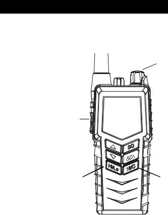
Keys and buttons
1.On/off/volume
2.Light/Lock
3.Push To Talk (PTT)
4.Up key
5.Down key
6.Hi/Lo output power
7.Squelch
8.Scan
9.Priority channel (16)/ Call channel
10.Loudspeaker/microphone
Chapter 2
1
2 

3
4


 7 5
7 5 


 8
8
6 |
9 |
 10
10
0845 |
3 |

Operation
Key presses
Pressing and holding certain keys gives access to additional functions, shown in the table below.
|
Short press |
Long press |
Extra long |
|
Key |
press |
|||
(1 beep) |
(2 beeps) |
|||
|
(3 beeps) |
|||
|
|
|
||
|
|
|
|
|
|
Show next available |
Run through available |
Run through |
|
|
item in the list (up or |
items, or |
available |
|
|
down). |
select tagged channels |
items if an A |
|
|
Default: Channel |
A (T) or B (S). |
or B channel |
|
|
|
is tagged |
||
|
selection |
|
||
|
|
|
||
|
|
|
|
|
|
Activate Squelch |
Monitor function. Open |
|
|
|
control (Adjust with |
Squelch completely. |
|
|
|
up/down arrows). |
|
|
|
|
|
|
|
|
|
1 press: Activate/ |
Add/Delete channel |
|
|
|
terminate Dual/Triple |
from memory scan. |
|
|
|
watch. |
|
|
|
|
2 presses: Activate |
|
|
|
|
memory scan. |
|
|
|
|
|
|
|
|
|
Toggle between high |
|
|
|
|
and low transmitter |
|
|
|
|
power. |
|
|
|
|
|
|
|
|
|
Select channel 16. |
Select programmed |
Program Call |
|
|
|
Call channel. |
channel. |
|
|
|
|
|
4 |
0845 |
Operation
The display
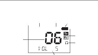
The display holds various fields of information, explained below.
4 |
5 |
6 |
3


 7 2
7 2 


8
1
9
10
1.Current working channel.
2.Current channel mode.
3.“Lo”: Reduced transmitter power.
Full transmitter power is not shown in display.
4.Dual watch activated.
5.Current working channel is marked for scanning.
6.Keypad is locked.
7.Battery level indicator.
8.Transmitting (Tx) /Receiving (Rx).
9.Accessory is connected.
10.Service line for various purposes. In this example the volume level.
0845 |
5 |
Operation
Using the ATEX VHF GMDSS
Basic functions
Note Before using the radio, mount the antenna at the top of the radio. The antenna is delivered with the radio.
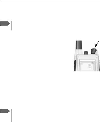
Switching the radio on and off
• To switch the radio on, turn the knob at the top of the radio clockwise.
The display lights up showing the last used channel and the battery level.
•To switch the radio off, Turn the knob back counter-clockwise until it clicks.
Selecting the working channel
•To select channel 16 (Distress or Safety), press the 16/C key.
•To select the Call channel, use a long press on 16/C.
•To select among all available channels, press Sor Ton the keypad. For fast selection, press and hold S or T.
The display shows the currently selected channel.
Note Long press on S or T can also be used to select preferred channels. For information on how to program preferred channels, see Configuring the ATEX VHF GMDSS on page 10.
6 |
0845 |
 Loading...