


 Loading...
USER & INSTALLATION MANUAL
SAILOR 6216 VHF DSC
Thrane & Thrane A/S
SAILOR 6216 VHF DSC Radio
User and installation manual
Document number: TT98-128825-THR-C
Release date: January 8, 2010
Disclaimer
Any responsibility or liability for loss or damage in connection with the use of this product and the accompanying documentation is disclaimed by Thrane & Thrane. The information in this manual is provided for information purposes only, is subject to change without notice and may contain errors or inaccuracies.
Manuals issued by Thrane & Thrane are periodically revised and updated. Anyone relying on this information should acquire the most current version e.g. from the Thrane & Thrane Extranet at: http://extranet.thrane.com.
Thrane & Thrane is not responsible for the content or accuracy of any translations or reproductions, in whole or in part, of this manual from any other source.
Copyright
© 2010 Thrane & Thrane A/S. All rights reserved. Printed in Denmark.
Trademark Acknowledgements
•SAILOR is a registered trademarks of Thrane & Thrane A/S.
•Other product and company names mentioned in this manual may be trademarks or trade names of their respective owners.

Safety warning
The following general safety precautions must be observed during all phases of operation, service and repair of this equipment. Failure to comply with these precautions or with specific warnings elsewhere in this manual violates safety standards of design, manufacture and intended use of the equipment. Thrane & Thrane assumes no liability for the customer's failure to comply with these requirements.
Warranty limitation
IMPORTANT - The radio is a sealed waterproof unit (classified IPX8). To create and maintain its waterproof integrity it was assembled in a controlled environment using special equipment. The radio is not a user maintainable unit, and under no circumstances should the unit be opened except by authorized personnel. Unauthorized opening of the unit will invalidate the warranty.
Installation and service
Installation and general service must be done by skilled service personnel.
iii
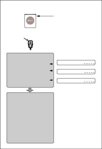
Emergency calls
Lift Cover
 Press RED Button
until acoustic and light-indication
becomes steady (more than 3 seconds)
Make sure your VHF Radio is on CH16
Use the HANDMICROPHONE for voice calling
MAYDAY-MAYDAY-MAYDAY |
|
|
|
|
|
|
|
|
OWN ID |
|||||||||||||||||||||||||
This is |
|
SHIP‘s NAME: |
|
|
|
|
|
|
|
|
|
|
|
|
|
|
|
|
|
|
|
|
|
|||||||||||
NAME-NAME-NAME |
|
|
|
|
|
|
|
|
|
|
|
|
||||||||||||||||||||||
|
|
|
|
|
|
|
|
|
|
|
|
|
|
|
|
|
|
|
|
|
|
|
|
|
|
|
|
|
|
|
|
|
||
|
|
|
|
|
|
|
|
|
|
|
|
|
|
|
|
|
|
|
|
|
|
|
|
|
|
|
|
|
|
|
|
|
||
CALLSIGN |
|
|
|
CALLSIGN: |
|
|
|
|
|
|
|
|
|
|
|
|
|
|
|
|
|
|
|
|
|
|
|
|
|
|
||||
|
|
|
|
|
|
|
|
|
|
|
|
|
|
|
|
|
|
|
|
|
|
|
|
|
|
|
|
|||||||
or other IDENTIFICATION |
|
|
|
|
|
|
|
|
|
|
|
|
|
|
|
|
|
|
|
|
|
|
|
|
|
|
|
|
|
|
|
|
||
MMSI |
|
|
|
MMSI: |
|
|
|
|
|
|
|
|
|
|
|
|
|
|
|
|
|
|
|
|
|
|||||||||
|
|
|
|
|
|
|
|
|
|
|
|
|
|
|
|
|
|
|
|
|
|
|
|
|
|
|
|
|||||||
|
|
|
|
|
|
|
|
|
||||||||||||||||||||||||||
(If the initial alert is sent by DSC) |
|
|
|
|
|
|
|
|
|
|
|
|
|
|
|
|
|
|
|
|
|
|
|
|
|
|
|
|
|
|
|
|
||
MAYDAY |
|
|
|
|
|
|
|
|
|
|
|
|
|
|
|
|
|
|
|
|
|
|
|
|
|
|
|
|
|
|
|
|
||
NAME of the VESSEL in distress |
|
|
|
|
|
|
|
|
|
|
|
|
|
|
|
|
|
|
|
|
|
|
|
|
|
|
|
|
|
|
|
|
||
CALLSIGN or other IDENTIFICATION |
|
|
|
|
|
|
|
|
|
|
|
|
|
|
|
|
|
|
|
|
|
|
|
|
|
|
|
|
|
|
|
|
||
MMSI |
|
|
|
|
|
|
|
|
|
|
|
|
|
|
|
|
|
|
|
|
|
|
|
|
|
|
|
|
|
|
|
|
||
(If the initial alert is sent by DSC) |
|
|
|
|
|
|
|
|
|
|
|
|
|
|
|
|
|
|
|
|
|
|
|
|
|
|
|
|
|
|
|
|
||
POSITION |
|
|
|
|
|
|
|
|
|
|
|
|
|
|
|
|
|
|
|
|
|
|
|
|
|
|
|
|
|
|
|
|
||
given as latitude and longitude |
|
|
|
|
|
|
|
|
|
|
|
|
|
|
|
|
|
|
|
|
|
|
|
|
|
|
|
|
|
|
|
|
||
or |
|
|
|
|
|
|
|
|
|
|
|
|
|
|
|
|
|
|
|
|
|
|
|
|
|
|
|
|
|
|
|
|
||
If latitude and longitude are not known |
|
|
|
|
|
|
|
|
|
|
|
|
|
|
|
|
|
|
|
|
|
|
|
|
|
|
|
|
|
|
|
|
||
or if time is insufficient, |
|
|
|
|
|
|
|
|
|
|
|
|
|
|
|
|
|
|
|
|
|
|
|
|
|
|
|
|
|
|
|
|
||
in relation to a known geographical location |
|
|
|
|
|
|
|
|
|
|
|
|
|
|
|
|
|
|
|
|
|
|
|
|
|
|
|
|
|
|
|
|
||
NATURE of distress |
|
|
|
|
|
|
|
|
|
|
|
|
|
|
|
|
|
|
|
|
|
|
|
|
|
|
|
|
|
|
|
|
||
Kind of ASSISTANCE required |
|
|
|
|
|
|
|
|
|
|
|
|
|
|
|
|
|
|
|
|
|
|
|
|
|
|
|
|
|
|
|
|
||
Any other useful INFORMATION |
|
|
|
|
|
|
|
|
|
|
|
|
|
|
|
|
|
|
|
|
|
|
|
|
|
|
|
|
|
|
|
|
||
99-129558
iv

Training information
The Sailor 6216 VHF radio is designed for "occupational use only" and is also classified as such. It must only be used in the course of employment by individuals aware of both the hazards as well as the way to minimize those hazards
The radio is thus NOT intended for use in an uncontrolled environment by general public. The Sailor 6216 has been tested and complies with the FCC RF exposure limits for "Occupational Use Only". The radio also complies with the following guidelines and standards regarding RF energy and electromagnetic energy levels including the recommended levels for human exposure:
•FCC OET Bulletin 65 Supplement C, evaluating compliance with FCC guidelines for human exposure to radio frequency electromagnetic fields.
•American National Standards Institute (C95.1) IEEE standard for safety levels with respect to human exposure to radio frequency electromagnetic fields, 3 kHz to 300 GHz
•American National Standards Institute (C95.3) IEEE recommended practice for the measurement of potentially hazardous electromagnetic fields - RF and microwaves.
Below the RF exposure hazards and instructions in safe operation of the radio within the FCC RF exposure limits established for it are described.
Warning
Your Thrane & Thrane radio set generates electromagnetic RF (radio frequency) energy when it is transmitting. To ensure that you and those around you are not exposed to excessive amounts of that energy (beyond FCC allowable limits for occupational use) and thus to avoid health hazards from excessive exposure to RF energy, FCC OET bulletin 65 establishes an Maximum Permissible Exposure (MPE) radius of 3' (0.9m) for the maximum power of your radio (25W selected) with an half wave omni-directional antenna having a maximum gain of 3 dB (5.2dBi). This means all persons
v

must be at least 3' (0.9m) away from the antenna when the radio is transmitting.
Installation
1.An omni-directional antenna with a maximum power gain of 5.2 dBi must be mounted at least 9.6' (2.9m) above the highest deck where people may be staying during radio transmissions. The distance is to be measured vertically from the lowest point of the antenna. This provides the minimum separation distance which is in compliance with RF exposure requirements and is based on the MPE radius of 3' (0,9m) plus the 6.6' (2m) height of an adult.
2.On vessels that cannot fulfil requirements in item 1, the antenna must be mounted so that its lowest point is at least 3' (0.9m) vertically above the heads of people on deck and all persons must be outside the 3' (0.9m) MPE radius during radio transmission.
• Always mount the antenna at least 3' (0.9m) from possible human access.
• Never touch the antenna when transmitting
• Use only authorized T&T accessories.
3.If antenna has to be placed in public areas or near people with no awareness of the radio transmission, the antenna must be placed at a distance not less than 6' (1.8m) from possible human access.
Failure to observe any of these warnings may cause you or other people to exceed FCC RF exposure limits or create other dangerous conditions
vi

Manual overview
This manual has the following chapters:
•Introduction contains a description of the VHF radio.
•Operation explains how to make and receive VHF and DSC calls, including how to use and set-up the channel scanning, the 2- way loudhailer, fog horn external loudspeaker.
•Installation explains how to mount the VHF radio and how to connect accessories and external equipment.
•Service & maintenance contains support information including lists of accessories and a troubleshooting guide.
vii

viii
|
Table of Contents |
|
Chapter 1 |
Introduction |
|
|
VHF radio with DSC ............................................................ |
1 |
Chapter 2 |
Operation |
|
|
General use and navigation ............................................... |
6 |
|
VHF radio communication ................................................. |
12 |
|
HI/LO transmission power ................................................ |
18 |
|
Watch ................................................................................ |
19 |
|
Scan ................................................................................. |
20 |
|
Radio setup ...................................................................... |
22 |
|
DSC calls .......................................................................... |
25 |
|
Phone book ....................................................................... |
41 |
|
Loudhailer with talk-back ................................................. |
44 |
|
Automatic foghorn ........................................................... |
45 |
|
Hailer and Fog horn setup ................................................ |
47 |
|
Replay function ................................................................ |
48 |
Chapter 3 |
Installation |
|
|
Unpacking the SAILOR 6216 VHF DSC ............................... |
49 |
|
Installing the VHF radio .................................................... |
50 |
|
Power, VHF antenna and external equipment .................. |
57 |
|
System setup .................................................................... |
62 |
|
SAILOR 6201 Handset cradle (optional) ............................. |
64 |
ix

Table of Contents |
|
|
Chapter 4 |
Service & maintenance |
|
|
Contact for support ........................................................... |
65 |
|
Maintenance .................................................................... |
65 |
|
Equipment and accessories .............................................. |
71 |
|
Warranty .......................................................................... |
71 |
App. A |
Technical specifications |
|
App. B |
Maritime channels |
|
Glossary |
......................................................................................... |
81 |
Index |
......................................................................................... |
83 |
x
Introduction
VHF radio with DSC
Chapter1111
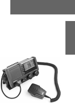
Introduction
SAILOR 6216 VHF DSC, your new SAILOR VHF radio with full DSC functionality, is approved to FCC and Industry Canada and is waterproof to the IPx8 and IPx6 standard. As part of the required safety equipment, use the SAILOR 6216 VHF DSC in an emergency situation. However the best way to guarantee functionality in an
emergency situation, is to use the radio in daily communication on board.
The VHF radio is a simplex/semi duplex VHF radio. It is designed with an easy- to-use menu-driven setup. You use the soft-keys to enter the desired functions, you browse and select a setting using the right selection wheel knob. The large display has red adjustable backlight which provides a good visibility even at night and protects your night vision.
The VHF radio can replay the last 90 s of received voice. This is a useful feature to minimize misunderstandings and to record messages when the radio is unattended.
The VHF radio connects easily to external equipment like a 2-way loudhailer and an external speaker. You can use the loudhailer as a 2-way on-board communicator. The loudhailer also functions as a fog horn. You can select from several programmed fog-horn patterns.
For a list of other accessories available for the SAILOR 6216 VHF DSC check with your nearest distributor.
1
Chapter 1: Introduction
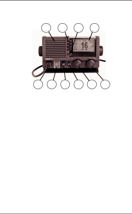
Controls on the front plate
1 |
2 |
3 |
4 |
5 |
6 |
7 |
8 |
9 |
10 |
1.Loudspeaker.
2.Four soft keys with function title in the display.
3.Quick selection key for channel 16 and the programmed preference channel.
4.Large display.
5.Connector for Handmicrophone or handset.
6.Button for sending a DSC Distress alert.
7.Squelch control to mute background noise.
8.Replay button to play back up to 90 s voice message.
9.Volume wheel knob with key-press function for volume control and power on/off.
10.Selector wheel knob with key-press function for changing the working channel, navigating in menus in the display and backlight dimming.
2 |
VHF radio with DSC |

Chapter 1: Introduction
SAILOR 6216 VHF DSC display
The picture shows the display
after start-up. The display holds |
|
|
|
1 |
2 |
|
|
|
|
|
|
|
|
||
various fields of information, |
|
|
|
|
|
|
|
|
HI/LO |
GPS Position |
US |
|
|||
depending on the currently |
3 |
4 |
|||||
|
|
|
|
||||
WATCH |
|
|
|||||
selected function. |
|
|
|
|
|||
|
|
|
|
|
|
||
|
CALL |
|
|
|
|||
|
|
|
|
|
|||
|
|
|
|
DISTRESS/CALL |
|
|
|
|
|
MORE... |
|
|
|||
1. Action line containing |
|
16 |
|
|
|||
information relevant for the |
|
|
|
5 |
|
|
|
currently selected function. |
|
|
|
|
|
||
|
|
|
|
|
|
||
2.Current working channel.
3.Functions you can select with the soft keys. If there are more than 3 functions in the list press the soft key MORE to display further functions.
4.Status and other values for the current state or VHF channel.
5.Service line containing current temporary information relevant for the current channel or function.
For a detailed description of the information shown for each of the functions available see the chapter Operation on page 5.
1111Introduction
VHF radio with DSC |
3 |

Chapter 1: Introduction
4 |
VHF radio with DSC |

|
Chapter 2 |
|
|
|
|
Operation |
2222 |
|
|
|
Note Before using the VHF radio make sure that the VHF antenna, power and other external equipment are connected properly. For instructions see chapter Installation on page 49.
In this chapter you find detailed instructions and guidelines for:
•General use and navigation
•VHF radio communication
•HI/LO transmission power
•Watch
•Scan
•Radio setup
•DSC calls
•Phone book
•Loudhailer with talk-back
•Automatic foghorn
•Replay function
Operation
5
Chapter 2: Operation
General use and navigation
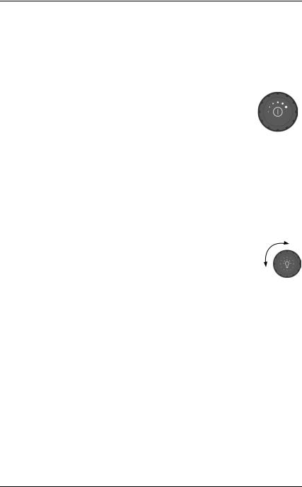
Power on and speaker volume
The VHF radio has a dual-function on/off wheel knob for power on/off and volume control.
•To power on the VHF radio press the on/off wheel knob.
•To power off the VHF radio, press and hold the on/off wheel knob and follow the instructions in the display.
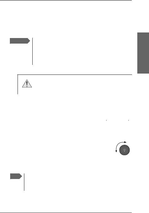
•To adjust the speaker volume, turn the volume wheel knob (clockwise = louder, counter clockwise = softer, until muted). When adjusted to the muted level 
 is shown in the display.
Working channel, settings and dim function
The selector wheel knob has several functions:
•To select the working channel, turn the selector wheel knob.
•To browse and select settings, turn the selector wheel knob and press for accept.
•To dim the backlight in the display until it is appropriate for the current situation, i.e. to give comfortable night vision, press, hold and turn the selector wheel knob (clockwise= more light).
6 |
General use and navigation |
Chapter 2: Operation
DSC and MMSI number
When the VHF radio is powered on for the first time, you must enter the vessel’s MMSI number. Hereafter the MMSI number is briefly displayed after power up. The MMSI is a unique, 9-digit identifier assigned to your ship.
Important The MMSI number must be programmed into the VHF radio to use any DSC functionality. The radio will prompt for the MMSI number at each power-up until the MMSI has been entered. An error message is displayed when trying to initiate any DSC function. However, you can use the radio in normal VHF mode.
2222Operation
Caution! Without a programmed MMSI number the
Distress button will not work!
Entering the MMSI number
When being prompted after power up enter the MMSI |
|
|
|
|
|
|
|
OK |
|
|
|
|
|
||
number as described below: |
|
MMSI MISSING |
|
||||
|
|
|
|
||||
BACK |
|
|
|||||
|
|
No DSC/Distress |
|
||||
|
|
|
|
|
|||
1. Enter the 9 digits one by one by turning the |
CANCEL |
|
Enter MMSI: |
|
|||
|
000000000 |
|
|
||||
selector wheel knob to the desired digit, press the |
|
|
|
|
|
||
|
|
|
|
|
|
|
|
selector wheel knob to accept the digit and |
|
|
|
|
|
|
|
|
|
|
|
|
|
|
|
advance to the next digit. |
|
|
|
|
|
|
|
To delete the previous digit press the soft key |
|
|
|
|
|
|
|
BACK. |
|
|
|
|
|
|
|
2.Press the soft key OK to confirm the entered MMSI number.
3.To leave without saving press the soft key CANCEL.
Note The MMSI number can be programmed by the operator once. If a wrong number has been entered and stored, or if there is a requirement to change it, contact your authorized dealer.
General use and navigation |
7 |

Chapter 2: Operation
Once programmed, you can see the MMSI number in the service line directly after start-up. The DSC functionality is operational at any time.
The message NO DSC (NO MMSI) is shown in the action line if the MMSI is not programmed.
HI/LO |
GPS Position INT |
||
16 |
|
||
|
|
|
|
MORE |
|||
WATCH |
|
|
|
CALL |
MMSI NUMBER |
|
|
219830067 |
|
||
|
|
|
|
|
|
|
|
Position and MMSI Information
To display position and MMSI information for the SAILOR 6216 VHF DSC radio, do as follows:
1.Press the soft key POS. If it is not in the display, press the soft key MORE until POS appears.
The display shows the current (latest) position (if a GPS is connected), the position UTC and type, GPS Status and MMSI.
2.You can enter the position and UTC manually. Turn the selector wheel knob to select the value you want to change. Then press and turn the selector wheel knob to enter the current position or UTC time. The display shows
Man Position.
3.Press the soft key SAVE to save the new value.
4.After you have entered a value manually or overruled the GPS input, a soft key UseGPS appears in the display if the GPS is available. Press this soft key if you decide to use the data from the connected GPS.
5.Press the soft key EXIT to return to normal use.
If the GPS was present and then disappears a warning appears in the display after 10 minutes. Follow the instructions on the screen.
8 |
General use and navigation |
Chapter 2: Operation
Speaker devices
The VHF radio can be equipped with the following speaking devices:
•SAILOR 6202 Handmicrophone with a PTT (Push To Talk) button.
•Handset with a microphone, ear piece and a PTT button. The volume in the ear piece can be adjusted, for details see Controller setup on page 10.
•Loudhailer.
•External speaker.
See Controller setup on page 10 for managing speaking devices.
Adjusting the squelch
With the Squelch control you can manually adjust and suppress noise in order to optimize the quality of the received radio communication.
•When hearing noise or an unwanted signal, turn the squelch button clockwise until the speaker is muted.
Functions
The following functions are available from top-level standby:
Soft key |
Function |
|
|
HI/LO |
Transmitter power, high or low |
|
|
WATCH |
Dual or triple watch |
|
|
CALL |
DSC calls |
|
|
POS |
Current position from GPS, including UTC time and |
|
MMSI number |
|
|
ALERT |
Make a distress call, categories can be assigned |
|
|
2222Operation
General use and navigation |
9 |

Chapter 2: Operation
Soft key |
Function |
|
|
SCAN |
Scanning function |
|
|
HAIL |
Loudhailer |
|
|
FOG |
Fog horn |
|
|
PBOOK |
Phone book |
|
|
SETUP |
Setup pages for RADIO, HAILER/FOG, SYSTEM, |
|
CONTROLLER and DSC |
|
|
The functions of the SAILOR 6216 VHF DSC are accessed and set using the four soft keys to the left
of the display. The current function of a soft key is shown in
the display next to the soft key. For
some applications there are two control levels
HI/LO |
GPS Position |
INT |
|
16 |
|
||
|
|
|
|
WATCH |
|
||
|
|
||
|
|
|
|
CALL |
|
|
|
MORE... DISTRESS/CALL
•A top level showing the current information and options for this application. This can be on one page, or on several pages.
•A setup screen showing the options you can configure for the specific application.
Use the soft key MORE to display further applications.
Controller setup
In the CONTROLLER SETUP you set handset volume, external speakers and display contrast. You can view the Software version and serial number.
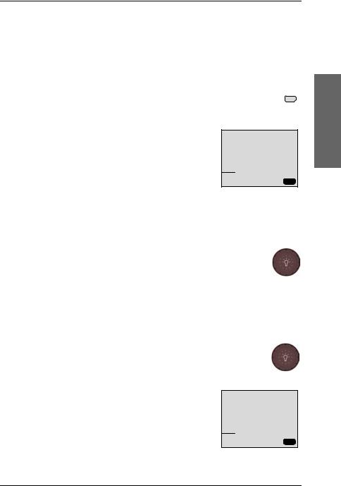
To change a setting in the CONTROLLER SETUP, do as follows:
1.Press the soft key SETUP. If it is not in the display, press the soft key MORE until SETUP appears.
2.Press the arrow soft key  or
or  to advance to CONTROLLER SETUP.
10 |
General use and navigation |

Chapter 2: Operation
3.Turn the selector wheel knob to go to a setting, then press the selector wheel knob to change the setting.
4. Press EXIT to return to normal radio operation.
Parameter |
Description |
|
|
Handset 1 vol: |
Adjust earpiece volume for handset 1: OFF, 1 to 14 |
|
Note: Default setting is OFF. If a handset is connected |
|
to the front connector this value must be configured |
|
to a value (1-14). |
|
|
Handset 2 vol: |
Adjust earpiece volume for handset 2: OFF, 1 to 14 |
|
Note: Default setting is OFF. If a handset is connected |
|
to the rear connector this value must be configured |
|
to a value (1-14). |
|
|
Ext. speaker |
FIX: Fixed level is set for external speaker |
|
REL: Relative level following volume adjustment of |
|
the internal speaker |
|
|
Ext. fix/rel vol: |
External speaker fix or rel volume: |
|
rel: -5 to 5. Offset relative to internal speaker steps |
|
fix: OFF, 1 to 14 |
|
|
Language |
English |
|
|
Contrast |
Display contrast, 1 to 5 |
|
|
Version |
Software version, read only |
|
|
Serial |
Serial number of the radio, read only. |
|
|
2222Operation
General use and navigation |
11 |
Chapter 2: Operation
VHF radio communication
In this section of the manual you find information on
•Basic VHF operation
•VHF channels
•Programming a call channel
•Naming a channel
Basic VHF operation
You can make VHF calls using the Handmicrophone or another speaking device.
Note A single, short press on the 16/C key will always bring you to channel 16, the international calling and distress channel, no matter which display the radio showed.
Quick guide to radio telephone calls
1.Press the PTT button on the speaking device. When the TX indicator lights up in the display, the transmission is active.
2.To enable reception of a radio signal release the PTT button.
TX RX
|
|
Press PTT only when you are talking. Always say “Over.” just before |
|
Note |
|||
releasing the PTT button. |
|||
|
|
||
|
|
|
|
Note |
|
One transmission is limited to 5 minutes duration. |
|
|
|
|
|
12 |
VHF radio communication |
Chapter 2: Operation
Receiving a radio telephone call on channel 16
When you hear your call name in the loudspeaker, proceed as follows:
1.An RX symbol shows that the radio is receiving on the working channel displayed.
HI/LO |
GPS Position |
US |
|
|
|
16 |
|
SCAN |
|
||
|
|
||
|
|
|
|
CALL |
|
|
|
|
|
|
|
MORE...DISTRESS/CALL |
RX |
||
2.Lift the Handmicrophone or take the handset.
3.Press the PTT key. A TX symbol shows that the radio is transmitting on the working channel displayed.
4.Repeat the name of the station calling you and say: “This is [your ship’s name]”.
HI/LO |
GPS Position |
US |
|
|
|
16 |
|
SCAN |
|
||
|
|
||
|
|
|
|
CALL |
|
|
|
MORE...DISTRESS/CALL TX
5.Suggest a working channel other than 16 by saying: “Channel [suggested channel number]”.
6.Say: “Over.” and release the PTT key to allow the caller to confirm the suggested new channel.
7.Switch to the new channel by turning the selector wheel knob to the agreed channel and begin your conversation. Press PTT only when you are talking.
Making a radio telephone call on channel 16
To make a radio telephone call, proceed as follows:
1.Select channel 16 by pressing the soft key 16/C or by turning the selector wheel knob.
2.Lift the handset or take the Handmicrophone.
3.Press the PTT key. A TX symbol shows that the VHF radio is transmitting on the working channel displayed.
4.Say the name of the station you are calling three times.
HI/LO |
GPS Position |
US |
|
|
|
16 |
|
SCAN |
|
||
|
|
||
|
|
|
|
CALL |
|
|
|
MORE...DISTRESS/CALL TX
2222Operation
VHF radio communication |
13 |

Chapter 2: Operation
5.Say: “This is [your ship’s name]”.
6.Say: “Over.” and release the PTT key to listen. An RX symbol shows that the radio is receiving on the working channel displayed
7.When answered, agree upon a working channel other than 16.
8.Switch to the new channel by turning the selector wheel knob to the agreed channel and begin your conversation.
HI/LO |
GPS Position |
US |
|
|
|
16 |
|
SCAN |
|
||
|
|
||
|
|
|
|
CALL |
|
|
|
|
|
|
|
MORE...DISTRESS/CALL |
RX |
||
VHF channels
You can change channels whenever the channel |
|
|
|
|
|
|
HI/LO |
|
GPS Position |
INT |
|||
|
|
|||||
designator is displayed. Turn the selector wheel knob to |
|
|
|
6 |
|
|
SCAN |
|
|
|
|||
browse through all channels that are available in the |
|
|
|
|||
|
|
|
|
|
||
CALL |
|
|
|
|||
selected channel mode. The channels appear in the |
|
|
|
|||
|
|
|
|
|
||
MORE... |
|
|
||||
display in the following order: |
INTERSHIP |
|
|
|||
|
|
|
|
|
|
|
|
HI/LO |
|
GPS Position |
|
US |
|
• Primary channels |
W2 |
|
||||
|
|
|
|
|
|
|
SCAN |
|
|
|
|
||
|
|
|
|
|
||
• Weather channels (if any) |
|
|
|
|
|
|
CALL |
|
|
|
|
||
|
|
|
|
|
|
|
• Private channels (if any) |
MORE... |
|
|
|
||
|
|
|
|
|
|
|
|
|
|
|
|
|
|
|
HI/LO |
|
GPS Position |
INT |
||
To quickly toggle between these 3 channel groups make |
|
P2 |
|
|
||
|
|
|
|
|
||
SCAN |
|
|
|
|||
a long press and release the selector wheel knob. The |
|
|
|
|
|
|
CALL |
|
|
|
|||
VHF radio toggles between the last selected channels in |
|
|
|
|
||
MORE... |
|
|
||||
the respective groups, i.e. the last selected weather
channel, the last selected private channel or the last selected primary channel. If there are no channels defined in a group, it is not selected.
VHF channel table |
Description |
|
|
Primary channels |
For details see Maritime channels on page 75. |
(no prefix) |
For instructions how to change a channel table see Radio |
|
setup on page 22. |
|
|
14 |
VHF radio communication |
|
Chapter 2: Operation |
|
|
VHF channel table |
Description |
|
|
Weather (WX) |
Weather channels have the prefix W. (For US and CA |
|
channels only.) |
|
|
Private (PRIV) |
Up to 40 user-defined private channels. Contact your dealer |
|
for programming private channels. |
|
|
Programming a call channel
To program a call channel (or quick selection), do as follows:
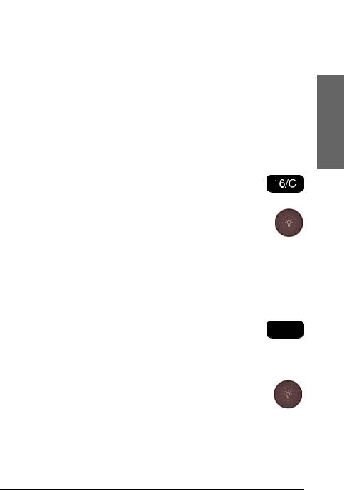
1.Make an extra-long press (2.5 s duration) on the 16/C key.
2.Press the soft key CALL CH. The channel designator is flashing.
3.Turn the selector wheel knob to select the desired channel.
4.Press the soft key OK to confirm the new call channel and leave edit mode.
Naming a channel
To name a channel, do as follows:
1.Make an extra long press on the 16/C key until NAME is shown
in the display next to one of the soft keys. 


2.Turn the selector wheel knob to select the channel you want to name.
3.Press the soft key NAME.
4.Turn and press the selector wheel knob to enter the name, letter by letter. Press BACK to move one character to the left. Press CLEAR to the delete the current character and the following characters. A long press on CLEAR deletes all characters.
2222Operation
VHF radio communication |
15 |

Chapter 2: Operation
5.Press the soft key OK to confirm the entered value and to leave edit mode.
6.Press EXIT to return to return to the standard VHF display.
|
|
PROGRAM |
INT |
OK |
|
14 |
|
|
|
||
BACK |
|
|
|
|
|
|
|
CLEAR |
|
|
|
|
|
|
|
CANCEL |
NEW_ |
|
|
|
|
|
|
Display for non-VHF applications
When the radio is used for functions other than VHF, the display is arranged differently. The large channel display moves to the bottom line along with selected icons.
The channel displayed in this line will always reflect the communication channel on which the radio is tuned into for communication.
If PTT is pressed the radio transmits on the displayed channel (not valid for hailer mode).
If a signal is received the signal is received on the displayed channel.
16 |
VHF radio communication |

Chapter 2: Operation
Engagement status
The radio is considered engaged when an active DSC-initiated communication is ongoing, or communication is active on non-DSC initiated VHF operation:
•A new channel selected
•PTT pressed or,
•Voice signal received
The engagement state is used to prohibit incoming DSC calls from taking over control of the transmitter channel, disrupting ongoing communication.
When the radio is engaged in VHF communication not initiated by DSC, this is indicated with the icon  in the lower right position of the display. Engagement will automatically time-out on inactivity (in the absence of any of the listed events above), and after an inactivity time specified in DSC setup, Comm Inactivity on page 39.
To terminate the engagement immediately press the soft key |
. |
Before the automatic disengagement, the icon  will flash. To prolong the engagement press the soft key
  .
.
2222Operation
VHF radio communication |
17 |

Chapter 2: Operation
HI/LO transmission power
Press the soft key HI/LO to toggle the transmit power between low (1 W) and high (25 W). If LO is not displayed, the transmit power is HI.
US channels: Local mode, 10 dB attenuation
To attenuate to the incoming signal, do as follows:
1.Press the soft key LOCAL to add 10 dB attenuation. If it is not in the display, press the soft key MORE until LOCAL appears in the display.
Note Local mode is automatically exited when using channel 16. If you want to use attenuation on channel 16 or a call channel, you must set it manually each time.
US channels: Overriding LOW power for channels 13 and 67
When running in US mode you can override low power on the alternative call channels 13 and 67. Do as follows:
1.With the VHF radio set to 13 and 67, press PTT on the speaking device.
2.Press the soft key OVRIDE to transmit with full power.
When you release the PTT button, the transmission power goes back to low.
18 |
HI/LO transmission power |
Loading...