


 Loading...
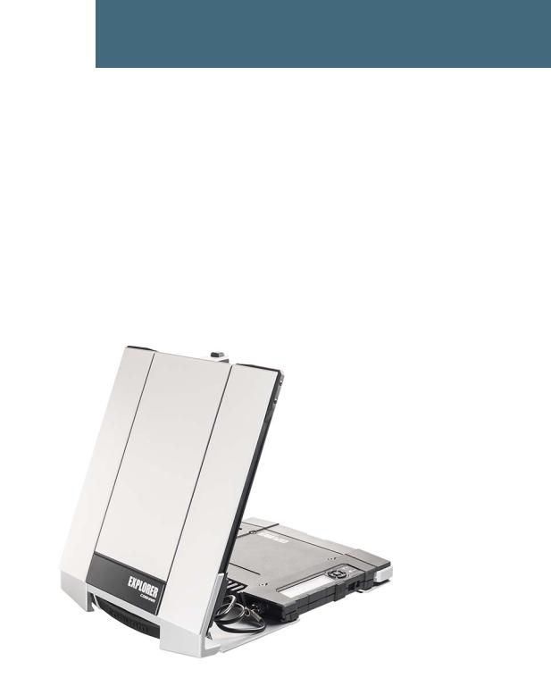
EXPLORER 710
User manual
Draft
Document number: 98-140012-DraftC1
Release date: 25 February 2014
Disclaimer
Any responsibility or liability for loss or damage in connection with the use of this product and the accompanying documentation is disclaimed by Thrane & Thrane A/S. The information in this manual is provided for information purposes only, is subject to change without notice and may contain errors or inaccuracies. Manuals issued by Thrane & Thrane A/S are periodically revised and updated. Anyone relying on this information should acquire the most current version e.g. from www.cobham.com/satcom or from the distributor. Thrane & Thrane A/S is not responsible for the content or accuracy of any translations or reproductions, in whole or in part, of this manual from any other source.
Thrane & Thrane A/S is trading as Cobham SATCOM.
Copyright
© 2014 Thrane & Thrane A/S. All rights reserved.
• |
Inmarsat is a registered trademark of the Interna ional Mari ime Sa elli e Organisation (IMSO) and |
• |
Other product and company n mes mentioned in this m nu l may be trademarks or trade names of |
|
their respective owners. |
|
Draft |
98-140012-DraftC1 |
ii |

Safety summary
The following general safety precautions must be observed during all phases of operation, service and repair of this equipment. Failure to comply with these precautions or with specific warnings elsewhere in this manual violates safety standards of design, manufacture and intended use of the equipment. Cobham SATCOM assumes no liability for the customer's failure to comply with these requirements.
Do not operate in an explosive atmosphere
Do not operate the equipment in the presence of flammable gases or fumes. Operation of any electrical equipment in such an environment constitutes a definite safety hazard.
Keep away from live circuits
Operating personnel must not remove equipment covers. Component replacement and internal adjustment must be made by qualified maintenance personnel. Do not replace components with the power cableDraftconnected. Under certain conditions, dangerous voltages may exist even with the power cable removed. To avoid injuries, always disconnect power and discharge circuits before touching them.
Do not service alone
Do not attempt internal service or adjustments unless ano her person, capable of rendering first aid resuscitation, is present.
Do not substitute parts or modify equipment
Because of the danger of introducing ddition l h z rds, do not substitute parts or perform any unauthorized modification to the equipment.
Keep away from antenna f ont
This device emits radio f equency ene gy when switched on. To avoid injury, keep a minimum safety dist nce of 1 m f om the ntenna front when the EXPLORER 710 is on.
For information on the safety distance f om the t ansceiver (WLAN), see the FCC/IC Radiation Exposure statement on the next page.
Garder à l'écart de l'avant de l'antenne
Le présent appareil émet des radiofréquences lors de son utilisation. Afin d'éviter tout risque pour la santé, une distance minimale de 1 mètre est nécessaire entre l'utilisateur et l'avant de
l'EXPLORER 710.
Pour plus d'informations à propos de la distance de sécurité avec l'appareil (WLAN), veuillez consulter Déclaration de l’IC sur l'exposition aux radiations sur la page suivante.
Only use approved batteries from Cobham SATCOM
Use of non approved batteries may result in explosion, fire, electrical shock or injury.
Observe marked areas
Under extreme heat conditions do not touch areas of the EXPLORER 710 that are marked with this symbol, as it may result in injury.
The terminal has been designed for full usability meaning that there are no restrictions to which interfaces can be used simultaneously. This means that you can use all the interfaces at once at any temperature
98-140012-DraftC1 |
iii |

within -25 to 55 C. Be aware that the terminal will get very hot when it is operated at 55 C with all interfaces active and it is therefore marked with a heating label.
FCC/IC Radiation Exposure statement
WLAN: Transceiver Unit (when separated from the Antenna Unit):
This equipment complies with FCC and IC radiation exposure limits for an uncontrolled environment. This equipment should be installed and operated at a distance greater than 20 centimeters (8 inches) between the transceiver unit and yourself or any bystander to comply with the Radiation Exposure Requirements.
Déclaration de l’IC sur l'exposition aux radiations
WLAN: L'émetteur-récepteur (quand séparé de l'antenne) :
Le présent appareilDraftest conforme aux limites de l’IC sur l'exposi ion aux rayonnements établies pour un environnement non-contrôlé. Le présent appareil doit ê re ins allé et utilisé à une distance minimum de 20 centimètres (8 pouces) entre l'éme eur-récep eur et l'u ilisateur ou tout autre individu pour être conforme à la réglementation en ma ière d'exposi ion radiologique.
98-140012-DraftC1 |
iv |

Antenna Safety Instructions
Antenna Safety Instructions
Use Only Manufacturer Supplied Antennas
Antenna Minimum Safe Distance: 1 m
Antenna Gain
Directional, with maximum gain of 14.6 dB with reference to isotropic.
The Federal Communications Commission has adopted a safety standard for human exposure to RF (Radio Frequency) energy which is below the OSHA (Occupational Safety and Health Act) limits.
Antenna Mounting
DraftThe antenna supplied by the manufac urer must be loca ed such that during radio transmission, no person or persons can come closer han he above indicated minimum
safe distance to the front face of the an enna, i.e. 1 m.
L'antenne fournie par le fabricant doit ê re placée de elle sor e que, durant les transmissions radio, personne ni aucun groupe de personnes ne puisse s'approcher à une distance inférieur à la dist nce de sécuri é minim l indiquée ci-dessus, c.-à-d., 1 m.
To comply with cu ent FCC RF Exposure limits, the antenna must be installed at or exceeding the minimum s fe dist nce shown bove, and in accordance with the requirements of the ntenna m nuf cturer or supplier.
Antenna Substitution
o not use any other antenna than the models supplied or recommended by the manufacturer. You may be exposing people to excess radio frequency radiation. You may contact the manufacturer for further instructions.
Radiation Warning
WARNING! Maintain a separation distance of at least 1 m from the front face of the antenna to a person.
You, as the qualified end-user of this radio device, must control the exposure conditions of bystanders to ensure the minimum separation distance (above) is maintained between the antenna and nearby persons, for satisfying RF Exposure compliance. The operation of this transmitter must satisfy the requirements of General Population/ Uncontrolled Environment. Only use the terminal when persons are at least the minimum distance from the front face of the antenna.
98-140012-DraftC1 |
v |

About this manual
About this manual
Intended readers
This manual is a user manual for the EXPLORER 710. The manual is intended for anyone who is using or intends to use the EXPLORER 710. No specific skills are required to operate the EXPLORER 710. However, it is important that you observe all safety requirements listed in the Safety summary in the beginning of this manual, and operate the EXPLORER 710 according to the guidelines in this manual.
Related documents
The following documents are related to this manual and to the EXPLORER 710 system.
Title and description |
|
Document |
|
number |
|
|
|
|
|
|
|
Draft |
|
|
EXPLORER 710 Getting Started, English |
98-139653 |
|
EXPLORER 710 Getting Started, Deu sch (German) |
98-140216 |
|
EXPLORER 710 Getting St rted, Fr nç is (French) |
98-140217 |
|
EXPLORER 710 Getting St rted, Esp ñol (Sp nish) |
98-140218 |
|
EXPLORER 710 Getting St |
ted, Русский (Russi n) |
98-140219 |
EXPLORER 710 Getting St |
ted, (Chinese) |
98-140220 |
EXPLORER 710 Getting Sta ted, (Japanese) |
98-140221 |
|
Typography
In this manual, typography is used as indicated below: Bold is used for the following purposes:
• To emphasize words.
Example: “Do not touch the antenna front during pointing”.
• To indicate what the user should select in the user interface. Example: “Select Control panel > LAN and click Enable”.
Italic is used to emphasize the paragraph title in cross-references. Example: “For further information, see Connecting Cables on page...”.
98-140012-DraftC1 |
vi |

Table of Contents
Chapter 1 |
Introduction to EXPLORER 710 |
|
|
General description .................................................................................................................. |
1 |
|
Features and interfaces of the EXPLORER 710 ............................................. |
2 |
|
Features .................................................................................................................................................... |
2 |
|
Overview of interfaces ...................................................................................................................... |
3 |
|
Your EXPLORER 710 terminal ......................................................................................... |
4 |
|
Overview .................................................................................................................................................. |
4 |
|
Display and keypad ............................................................................................................................. |
5 |
|
User interfaces ...................................................................................................................................... |
6 |
|
Antenna .................................................................................................................................................... |
6 |
|
Draft |
|
|
Compass .................................................................................................................................................. |
7 |
|
Battery ...................................................................................................................................................... |
7 |
|
SIM card .................................................................................................................................................. |
7 |
Chapter 2 |
Getting Started |
|
|
Unpacking and ssembling ................................................................................................ |
8 |
|
Initial inspection .................................................................................................................................. |
8 |
|
What’s in the delive y ........................................................................................................................ |
8 |
|
To open the t anspo t latch ........................................................................................................... |
9 |
|
To detach the antenna (optional) ............................................................................................... |
9 |
|
To insert the SIM card .................................................................................................................... |
11 |
|
To insert the battery ........................................................................................................................ |
11 |
|
To remove the battery .................................................................................................................... |
12 |
|
To remove the SIM card ................................................................................................................ |
12 |
|
Connecting cables ................................................................................................................... |
13 |
|
Connectors ........................................................................................................................................... |
13 |
|
To connect the antenna ................................................................................................................ |
14 |
|
To connect power ............................................................................................................................. |
14 |
|
Starting up the EXPLORER 710 ................................................................................... |
15 |
|
Automatic power up ........................................................................................................................ |
15 |
|
To switch the EXPLORER 710 on or off .................................................................................. |
15 |
|
To enter the SIM PIN ...................................................................................................................... |
15 |
|
To point the antenna ....................................................................................................................... |
16 |
|
The registration procedure ........................................................................................................... |
17 |
98-140012-DraftC1 |
vii |

Table of Contents
|
Making the first call or data session ...................................................................... |
18 |
||
|
To make the first call ....................................................................................................................... |
|
18 |
|
|
To make the first data connection (LAN) .............................................................................. |
19 |
||
|
To make the first data connection (WLAN) .......................................................................... |
19 |
||
|
Fixed antenna installation ............................................................................................... |
20 |
||
Chapter 3 |
Using the EXPLORER 710 |
|
||
|
User interfaces ............................................................................................................................ |
|
21 |
|
|
Enabling or disabling an interface ............................................................................................. |
22 |
||
|
Using a Computer, smartphone or tablet ......................................................... |
23 |
||
|
Overview ................................................................................................................................................ |
|
|
23 |
|
Draft |
|
||
|
To choose an interface for data connec ion ....................................................................... |
23 |
||
|
Router function .................................................................................................................................. |
|
|
23 |
|
Standard or Streaming data ......................................................................................................... |
|
24 |
|
|
To connect to the WLAN inter ace .......................................................................................... |
24 |
||
|
To connect to the LAN inter |
ce ............................................................................................... |
25 |
|
|
To start or stop |
d ta connection (LAN or WLAN) using the display ..................... |
26 |
|
|
Using PPPoE (Point-to-Point P otocol over Ethernet) ..................................................... |
27 |
||
|
To access the te min l using AT comm nds ....................................................................... |
29 |
||
|
To access the te min l f om |
emote loc tion ................................................................ |
29 |
|
|
Using a phone .............................................................................................................................. |
|
31 |
|
|
Call types ............................................................................................................................................... |
|
|
31 |
|
To connect a phone using LAN or WLAN .............................................................................. |
31 |
||
|
To connect an analogue phone ................................................................................................. |
33 |
||
|
To connect an IS |
N phone or modem .................................................................................. |
34 |
|
|
To make or receive a phone call with EXPLORER 710 ..................................................... |
35 |
||
|
Local numbers and special functions ....................................................................................... |
36 |
||
|
To charge your smartphone or tablet ..................................................................................... |
37 |
||
|
Viewing event messages .................................................................................................... |
37 |
||
|
Adjusting the display ............................................................................................................ |
|
37 |
|
|
Automatic power up .............................................................................................................. |
|
37 |
|
|
Viewing properties of the EXPLORER 710 ........................................................ |
38 |
||
|
Tracking the terminal ........................................................................................................... |
|
38 |
|
Chapter 4 |
Using the web interface |
|
||
|
Introduction .................................................................................................................................. |
|
|
40 |
98-140012-DraftC1 |
viii |

Table of Contents
The web interface ............................................................................................................................. |
40 |
To access and navigate the web interface ............................................................................ |
40 |
Entering the SIM PIN in the web interface .................................................... |
43 |
Do you need a SIM PIN? ................................................................................................................ |
43 |
To enter the SIM PIN ...................................................................................................................... |
43 |
To cancel the SIM PIN .................................................................................................................... |
43 |
Pointing the antenna ............................................................................................................ |
44 |
Using the Dashboard ............................................................................................................. |
45 |
To start and stop data connections ......................................................................................... |
45 |
To change the name of your data connections ................................................................. |
46 |
Viewing status ............................................................................................................................. |
47 |
The Control panel .................................................................................................................... |
47 |
OverviewDraft................................................................................................................................................ |
55 |
Using the Logs ............................................................................................................................. |
48 |
To access the Logs ............................................................................................................................ |
48 |
Call log .................................................................................................................................................... |
48 |
Data log .................................................................................................................................................. |
48 |
Total counte s ..................................................................................................................................... |
48 |
Configu ing the LAN inte f ce ..................................................................................... |
49 |
Configu ing the WLAN inte f ce ............................................................................... |
50 |
Port forwa ding ........................................................................................................................... |
51 |
User group settings (LAN and WLAN) ................................................................... |
52 |
Configuring the Phone interface ............................................................................... |
53 |
Configuring the IS N interface .................................................................................. |
54 |
Configuring the USB interface ..................................................................................... |
54 |
Managing IP handsets or smartphones .............................................................. |
55 |
To manage IP handsets or smartphones in your EXPLORER 710 ............................... |
55 |
Support ............................................................................................................................................... |
56 |
To create a diagnostics report .................................................................................................... |
56 |
To view the event list ...................................................................................................................... |
57 |
To update software .......................................................................................................................... |
57 |
To view extended status ................................................................................................................ |
57 |
To reset the administrator password ....................................................................................... |
58 |
About ....................................................................................................................................................... |
58 |
Configuring the terminal settings ............................................................................ |
58 |
98-140012-DraftC1 |
ix |

Table of Contents
To set up power-up mode with external power ................................................................. |
58 |
To set up pointing at power up .................................................................................................. |
58 |
To enable or disable the pointing sound ............................................................................... |
59 |
To select the GNSS type ................................................................................................................ |
59 |
Viewing the battery status .............................................................................................. |
59 |
Setting up tracking .................................................................................................................. |
60 |
Advanced settings ................................................................................................................... |
62 |
First time use ....................................................................................................................................... |
62 |
Administrator password ................................................................................................................. |
62 |
Call charges .......................................................................................................................................... |
64 |
To restore factory settings ........................................................................................................... |
64 |
To enable or disable the use of a SIM PIN ............................................................................ |
64 |
Draft |
|
To change the SIM PIN .................................................................................................................. |
65 |
To set up user permissions ........................................................................................................... |
65 |
Link monitoring .................................................................................................................................. |
66 |
Data limits ............................................................................................................................................. |
66 |
Remote management ...................................................................................................................... |
67 |
Remote cont ol of t cking ........................................................................................................... |
70 |
To clear the logs ................................................................................................................................. |
70 |
To reset the total counte s ........................................................................................................... |
70 |
Chapter 5 Maintenance and t oubleshooting |
|
Getting support .......................................................................................................................... |
71 |
Contact information ........................................................................................................................ |
71 |
Repacking for shipment .................................................................................................................. |
71 |
Software update ........................................................................................................................ |
72 |
To upload software using the web interface ....................................................................... |
72 |
To upload software with USB ...................................................................................................... |
72 |
Recovery software upload ............................................................................................................ |
73 |
Maintenance ................................................................................................................................. |
74 |
Normal use of the battery ............................................................................................................. |
74 |
To recharge batteries ...................................................................................................................... |
74 |
To connect an extra, external EXPLORER 710 battery .................................................... |
75 |
Accurate display of the battery capacity ............................................................................... |
75 |
Storage ................................................................................................................................................... |
76 |
Disposal of the EXPLORER 710 ................................................................................................... |
76 |
98-140012-DraftC1 |
x |
Table of Contents
App. A
App. B
Troubleshooting ........................................................................................................................ |
77 |
Troubleshooting guide .................................................................................................................... |
77 |
Status signalling ................................................................................................................................. |
83 |
List of messages ................................................................................................................................. |
84 |
Log files .............................................................................................................................................. |
86 |
Diagnostics report ............................................................................................................................. |
86 |
Call log and data log ......................................................................................................................... |
86 |
Technical specifications |
|
General specifications ......................................................................................................... |
87 |
Battery specifications .......................................................................................................... |
88 |
Interfaces specifications .................................................................................................. |
89 |
Draft |
|
Power input .......................................................................................................................................... |
89 |
External battery connector ........................................................................................................... |
89 |
Phone interface .................................................................................................................................. |
90 |
ISDN interface .................................................................................................................................... |
91 |
LAN interface, 2-po t ....................................................................................................................... |
92 |
WLAN access point ........................................................................................................................... |
93 |
USB (Host) inte f ce ........................................................................................................................ |
93 |
Antenna inte face on t ansceiver .............................................................................................. |
94 |
etachable BGAN antenna ............................................................................................. |
94 |
Satellite coverage .................................................................................................................... |
95 |
Inmarsat I-4 coverage .................................................................................................................... |
95 |
Inmarsat Alphasat coverage ........................................................................................................ |
95 |
Conformity |
|
General ................................................................................................................................................ |
96 |
CE (R&TTE) ........................................................................................................................................... |
96 |
IC ............................................................................................................................................................... |
96 |
FCC ........................................................................................................................................................... |
97 |
Glossary |
......................................................................................................................................................................99 |
Index ................................................................................................................................................................... |
102 |
98-140012-DraftC1 |
xi |
Chapter 1
Introduction to EXPLORER 710
General description
The EXPLORER 710 is a handy portable terminal supporting simultaneous voice and data communication over BGAN. It provides versatility and high speed access with multiple interfaces for countless applications. Just connect your phone, laptop, smartphone or tablet, point the antenna towards the BGAN satellite - and you are online.
The EXPLORERDraft710 provides access to the highest bandwidth available on the BGAN network. With BGAN HDR (High Data Rate) you get a portfolio of four channel streaming rates including symmetric and asymmetric options so you only pay for the data you need. The system offers multi-user as well as single-user functionality, making it a flexible solution for a variety of applications, such as:
•Broadcasting
•Internet browsing
•Phone services
•Large file transfers
98-140012-DraftC1 |
General description |
1 |

Chapter 1: Introduction to EXPLORER 710
•Video conference and Streaming
•VPN (Virtual Private Network) access to corporate servers
The EXPLORER 710 can withstand severe environmental conditions such as humidity, dust, extreme weather and changing temperatures. It is small in size and fits easily into a backpack or similar. With the detachable antenna it is well suited for temporary camps or fixed installations.
Features and interfaces of the EXPLORER 710
Features
Full duplex, single or multi-user, standard data up to 492 kbps
Support for streaming data at 32, 64, 128, 176, 256 kbps, HDR (asymmetric or symmetric) and BGANDraftX-Stream
Standard LAN w. PoE, WLAN, ISDN and Phone por s and USB Host interface
Detachable antenna with integrated transceiver s and and ransceiver-to-antenna range up to 100 m/328 ft.
Built-in DHCP/NAT wireless router
Solar panel direct inte f ce
Support for batte y hot sw p
10-32 V C input
100-240 VAC power adapter
Built-in web interface allowing you to manage your calls and customize the terminal to your specific needs, using a smartphone, computer or tablet.
Point-to-Point Protocol over Ethernet (PPPoE)
Built-in PBX managing voice communication
CE, FCC, GMPCS and IC certified
98-140012-DraftC1 |
Features and interfaces of the EXPLORER 710 |
2 |
Chapter 1: Introduction to EXPLORER 710
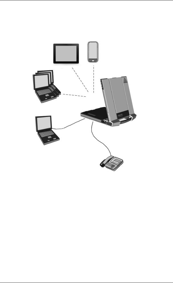
Overview of interfaces
The EXPLORER 710 provides a number of interfaces for connection of various types of computers, phones and other equipment.
Smartphone
Tablet
WLAN
DraftLAN ISDN or
Phone
Using the EXPLORER 710 on page 21 describes how to use each of the available interfaces.
Minimizing power consumption
The EXPLORER 710 is designed for minimum power consumption. This means that functions that are not currently used will automatically go into a “sleep mode” to minimize the power consumption. In addition to this automatic sleep mode function, you can disable each of the interfaces if they are not currently used. Note, however, that you will not be able to use these interfaces until you enable them again. For information on how to enable/disable interfaces, see Enabling or disabling an interface on page 22.
98-140012-DraftC1 |
Features and interfaces of the EXPLORER 710 |
3 |
Chapter 1: Introduction to EXPLORER 710
Your EXPLORER 710 terminal
Overview
The EXPLORER 710 is a compact unit comprising a transceiver with a detachable antenna, compass, display and keypad, all in one unit.
Transport lock
|
Antenna |
|
|
|
|
|
|
||
|
for BGAN |
|
|||||||
|
and GNSS |
|
|||||||
|
Draft |
Antenna for |
|||||||
|
Display and |
Wireless LAN |
|||||||
|
keypad |
|
|||||||
Battery |
|
|
|
|
|
|
|
Compass |
|
SIM card |
Connectors |
||||||||
|
|||||||||
|
(behind the battery) |
|
|||||||
98-140012-DraftC1 |
Your EXPLORER 710 terminal |
4 |

Chapter 1: Introduction to EXPLORER 710
Display and keypad
The EXPLORER 710 has a display and keypad providing quick access to important functions and simple setup, and for displaying status.
3 |
4 |
5 |
6 |
7 |
|
1.Menu:DraftOpens the display menu. For a menu overview, see next page.
2.Connect: Allows you to start a data connec ion.
3.Signal strength: Shows the sign l strength of the s tellite connection and whether the connection is global be m (G), egion l be m (R) or narrow beam (N). Press OK to see the GPS position.
4.Interfaces on/off: Allows you to switch the interf ces on or off. Disabled interfaces are crossed out.
5.Warning: Shows if the e a e wa ning messages. Press OK to see the messages.
6.Battery status: Shows remaining time for the internal battery and the external battery (if connected).
7.Keypad for navigation: Allows you to move between the available options (arrow keys) and select them (OK).
8.Status indicator: Shows status of the EXPLORER 710. For information on functions, see
Status indicator on page 83.
9.Status text: Shows the current status of the EXPLORER 710 and the network connection. For example, the text may show the status during start-up (see The registration procedure on page 17).
To navigate the display functions
•To highlight one of the icons, use the arrow buttons.
•To move around between the icons, use the arrow buttons.
•To select menu items, functions or values, press the OK key.
98-140012-DraftC1 |
Your EXPLORER 710 terminal |
5 |

The white part of the EXPLORER 710, including the support bracket, is the detachable antenna module. The antenna module comprises a GNSS (Global Navigation Satellite System) antenna and a BGAN antenna.
A Wireless LAN antenna is located on the transceiver unit.
98-140012-DraftC1 |
Your EXPLORER 710 terminal |
6 |

Chapter 1: Introduction to EXPLORER 710
Compass
The EXPLORER 710 also provides a compass to help positioning the antenna. For further information on how to use the compass, see To point the antenna on page 16.
Battery
The EXPLORER 710 comes with a rechargeable battery, which is easily inserted. The battery is automatically recharged when power is applied to the EXPLORER 710. The Status indicator shows that the battery is charging. See User interfaces on page 6.
Time between recharging depends on the use. The display shows estimated time left for the battery.
The EXPLORERDraft710 requires a SIM card to go online. Wi hout a SIM card you can still configure the terminal and you may be able to make emergency calls if he ne work allows it, but you
cannot make normal calls nor access the in ernet.
98-140012-DraftC1 |
Your EXPLORER 710 terminal |
7 |

Chapter 2
Getting Started
This chapter describes:
•Unpacking and assembling
•Connecting cables
•Starting up the EXPLORER 710
•Making the first call or data session
•Fixed antenna installation
Unpacking and assembling
Initial inspectionDraft
Inspect the shipping carton immedi tely upon receipt or evidence of damage during transport. If the shipping c rton is severely dam ged or water stained, request that the carrier's agent be present when opening the c ton. S ve the c rton packing material for future use.
WARNING! To void elect ic shock, do not apply power to the system if the e is ny sign of shipping damage to any p t of the f ont or re r p nel or the outer cover. Read the safety summary at the front of this manual befo e installing or ope ating the system.
After unpacking the system, inspect it thoroughly for hidden damage and loose components or fittings. If the contents are incomplete, if there is mechanical damage or defect, or if the system does not work properly, notify your dealer.
What’s in the delivery
The following items are included in the delivery:
•EXPLORER 710 terminal including transceiver, antenna and antenna cable
•Battery pack
•AC/DC adapter
•Getting started kit including:
•Ethernet/ISDN cable, 2 m screened
•Getting started booklet
98-140012-DraftC1 |
Unpacking and assembling |
8 |
Chapter 2: Getting Started
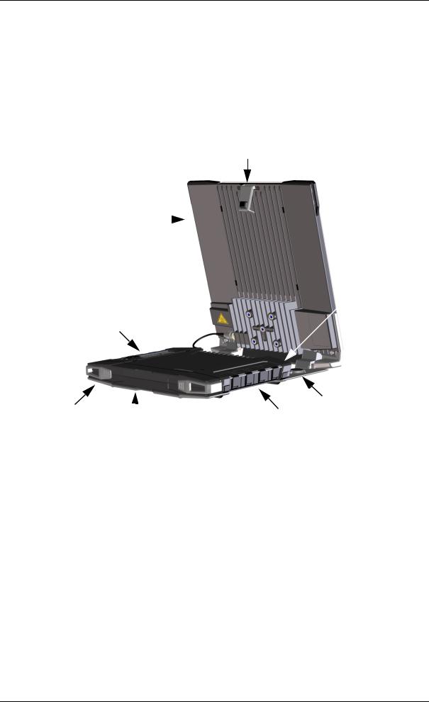
To open the transport latch
The EXPLORER 710 has a transport latch, securing the transceiver and antenna during transport.
1.Lift the transport latch to open the terminal.
2.Flip up the antenna module.
You can now access the keypad and connectors on the EXPLORER 710.
To detach |
|
Draft |
Antenna |
|
|
|
|
|
|
|
• Attached. You can go through the pointing process with the antenna and transceiver |
|||
|
attached as one unit. This means you have to move the entire terminal in order to point |
|||
|
the antenna towards the BGAN satellite. If you choose this option, make sure you connect |
|||
|
all cables including the short antenna cable, and enter the PIN, before pointing the |
|||
|
antenna. If not, you may accidently move the antenna when you connect cables or enter |
|||
|
the PIN. |
|
|
|
|
module and use it as a separate antenna. |
|
|
|
|
With the antenna separated from the |
|
|
|
|
transceiver, it is easier to use the transceiver |
|
|
|
|
without accidently moving the antenna. |
|
|
|
|
Also, you can choose the optimum location |
Transceiver |
|
|
|
for the antenna while keeping the |
|
|
|
|
transceiver in a more comfortable location. |
|
|
|
Important Do not place the transceiver in front of the antenna module!
The antenna emits radio frequency energy, which can affect the transceiver.
98-140012-DraftC1 |
Unpacking and assembling |
9 |
Chapter 2: Getting Started
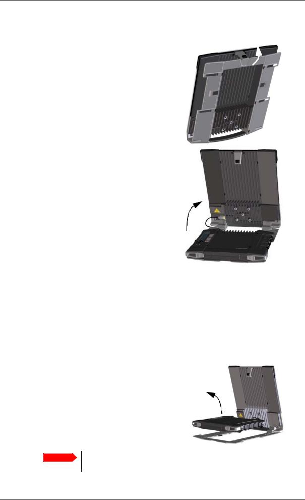
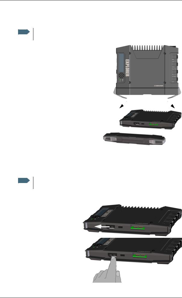
To detach the antenna, do as follows:
1.Locate the slide locks on the bottom of the terminal.
2.Press and slide the locks outwards while lifting the transceiver to release it from the antenna bracket.
3. Remove the transceiver from the antenna bracket.
4.To moveDraftthe antenna and transceiver ur her apar , disconnect the short ntenna c ble nd connect longer antenna cable between the ntenna nd the transceiver.
98-140012-DraftC1 |
Unpacking and assembling |
10 |
Chapter 2: Getting Started
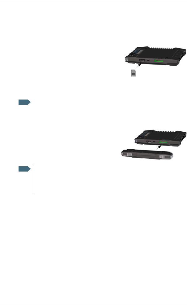
To insert the SIM card
The SIM card is provided by your Airtime Provider. Insert the SIM card as follows:
1.Locate the SIM slot on the same side where the battery is inserted.
2.Insert the SIM card into the SIM slot with the chip side facing up.
3.Press gently until it clicks.
4. Slide the lock in front of the SIM slot.
To insert the battery
|
Draft |
|
|
|
The battery should not be partially charged oo of en. For further information on the |
Note |
|
|
|
|
battery, see Maintenance on page 74. |
Do as follows: |
||
1. Insert the battery so that the connec or i s in o the battery slot, indic ted in the igure.
2. Press gently until it locks.
Note Before using the te minal the fi st time: to ensure accurate information on the battery capacity you should fully charge, then fully discharge the battery, and finally recharge the batte y while it is inse ted in the terminal. The EXPLORER 710 can be used during the discharging process, but the remaining battery capacity may not be displayed correctly.
98-140012-DraftC1 |
Unpacking and assembling |
11 |
Chapter 2: Getting Started
To remove the battery
Note For protection of the transceiver, always leave the battery inserted. Only remove the battery to replace it.
To remove the battery, do as follows:
1. If the transceiver and antenna are attached, open the transport latch and detach the antenna as described in To detach the antenna (optional) on page 9.
2. On the transceiver, open the battery latches as shown.
To remove the SIM ca d
3. RemoveDraftthe battery.
To remove the SIM ca d, fi st emove the battery as described in To remove the battery on the previous page.
Note When the SIM card is removed you cannot make calls or data sessions, but you can still use the display menu system and the built-in web interface to set up the terminal.
Remove the SIM card as follows:
1. Slide the lock aside to open the SIM slot as shown.
2.Gently press the SIM card and let it pop out of the slot.
3.Remove the SIM card.
98-140012-DraftC1 |
Unpacking and assembling |
12 |
Chapter 2: Getting Started
Connecting cables
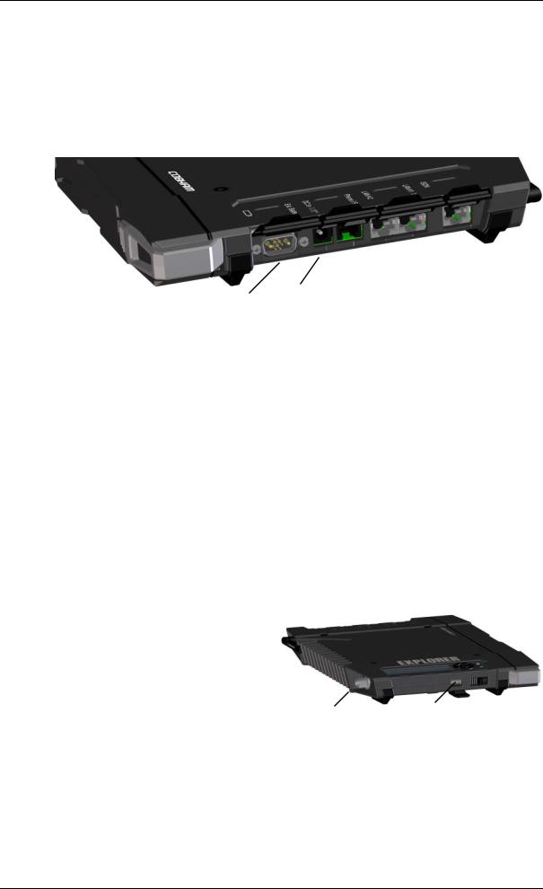
Connectors
The connector panel is placed on the side of the EXPLORER 710 and has the following connectors:
|
|
|
|
|
|
|
|
|
|
|
|
|
|
|
|
|
|
|
|
|
|
|
|
|
|
|
|
|
|
|
|
|
|
ISDN |
|
|
|
|
|
|
LAN1 |
|||
|
|
|
LAN2 |
|||||
|
Phone |
|
|
|||||
External battery DC in |
|
|
(PoE) |
|
|
|||
|
|
|
|
|
|
|
|
|
•1 Ext batteryDraftconnector for connec ing an ex ra EXPLORER 710 battery.
(up to 2 A) and for recovery update of software.
See To charge your smartphone or
tablet on page 37 and |
Antenna |
USB (Host) |
To upload software with USB on |
|
|
page 72. |
|
|
•1 antenna connector for connecting the antenna module of the EXPLORER 710. See the next section.
98-140012-DraftC1 |
Connecting cables |
13 |
Chapter 2: Getting Started
To connect the antenna
The antenna cable is connected at delivery.
Note If you want to use the antenna separated from the transceiver, use a longer antenna cable and
remove the transceiver from the antenna bracket. See the To detach the antenna (optional) on page 9.
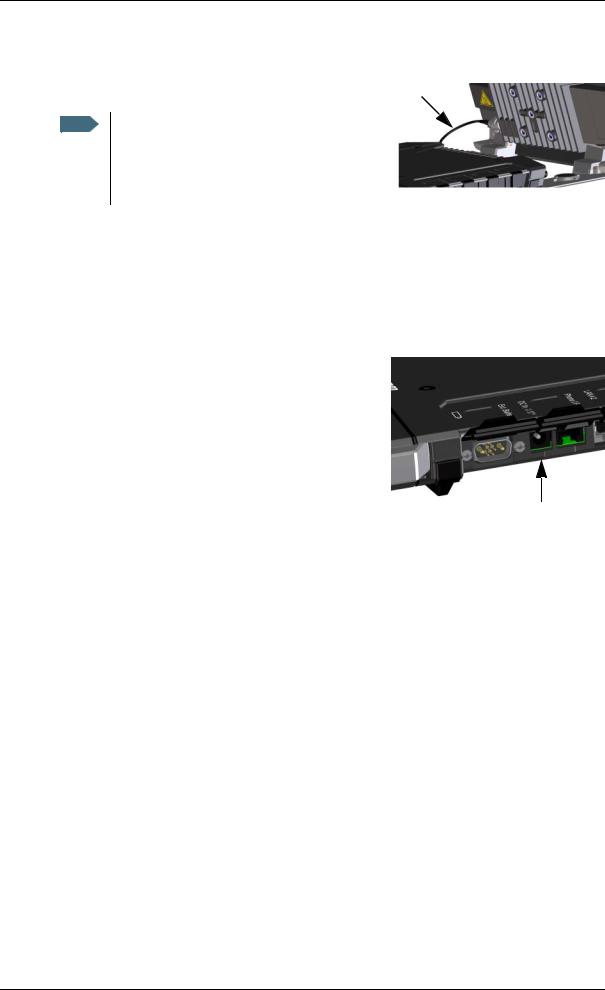
To connect power
When you connect external power to the DC input, the battery is charged while maintaining normal operation.
DC input
Refer to Technical specifications on page 87 |
or |
|
|
|
|||
specifications and pin-out for the DC Power input. |
|
|
|
||||
To power the terminal or to charge the ba ery, connect |
|
|
|
||||
one of the following external power sources |
o he DC |
|
|
|
|||
input: |
|
|
|
|
|
||
• |
10-32 VDC |
|
|
|
|
||
• |
The supplied AC/DC d pter connected to 100- |
|
|
|
|||
DC |
input |
||||||
|
240 V Mains |
|
|||||
|
|
Draft |
|
|
|
||
• A solar panel (min. 65 W, 10-32 VDC) |
|
|
|
|
|||
98-140012-DraftC1 |
Connecting cables |
14 |
Chapter 2: Getting Started
Starting up the EXPLORER 710
Automatic power up
The default behaviour of the EXPLORER 710 is to power up automatically when you connect external power. If you wish, you can change this power up mode, so that the EXPLORER 710 is only powered if the Power button is pressed.
For further information on power up mode, see Automatic power up on page 37.
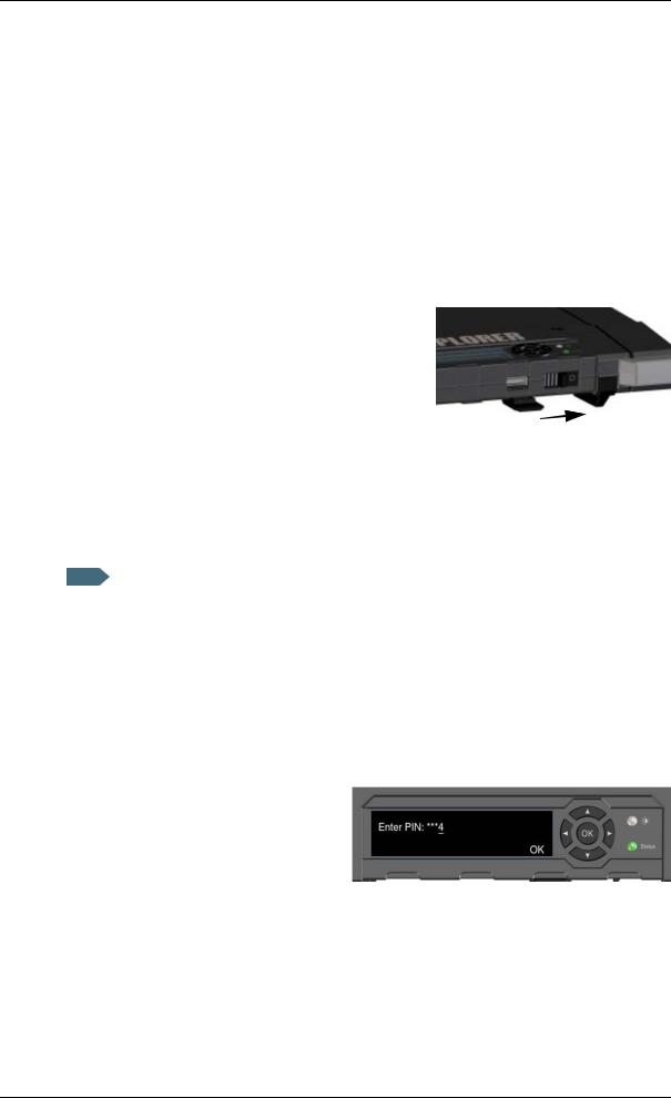
To switch the EXPLORER 710 on or off
1.Slide and hold the power button until the Status indicator lights up. This may take some seconds.
To enter |
|
Draft |
||
|
|
|
||
|
|
|
|
|
|
|
|
|
|
|
|
|
||
1. |
When the display shows Enter PIN?, highlight the text using the arrow keys and press OK. |
|||
|
|
If you select Cancel, the startup procedure is continued, but you will not be able to make |
||
|
|
calls or data sessions over the satellite network. See the previous section. |
||
2. |
Press or a number of times until the first digit is correct. |
|||
3. |
Press OK to go to the next digit. |
|||
|
|
The previous digit is indicated by a *. |
||
4. |
After pressing OK to enter the last |
|||
|
|
digit, press OK again to apply the PIN. |
||
For an overview of the display and keypad, see Display and keypad on page 5.
For information on how to enter the PIN in the web interface, see To enter the SIM PIN on page 43.
98-140012-DraftC1 |
Starting up the EXPLORER 710 |
15 |
Chapter 2: Getting Started
To point the antenna
Note You can choose to cancel pointing. In this case you cannot communicate on the BGAN network, but you can access all terminal settings.
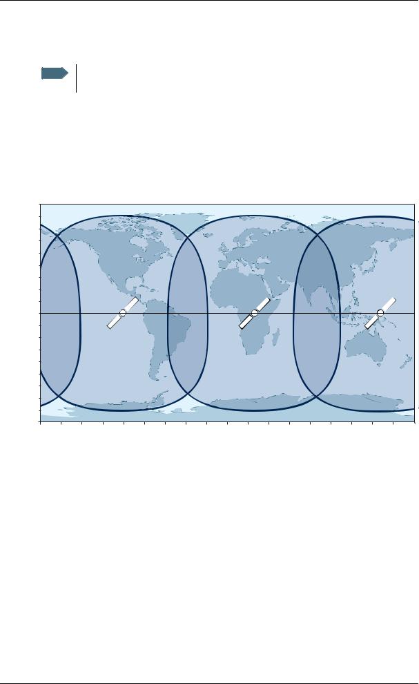
Before pointing
Before pointing the antenna you can use the coverage map below to find your approximate location in relation to the satellites. Then you can use the compass to find the pointing direction to the closest satellite.
The 3 Inmarsat satellites are positioned above the equator, at the centre of each “footprint”.
90° |
|
|
|
|
|
|
|
|
|
|
|
|
|
|
|
|
|
|
80° |
|
|
|
|
|
|
|
|
|
|
|
|
|
|
|
|
|
|
70° |
|
|
|
|
|
|
|
|
|
|
|
|
|
|
|
|
|
|
60° |
|
|
|
|
|
|
|
|
|
|
|
|
|
|
|
|
|
|
50° |
|
|
|
|
|
|
|
|
|
|
|
|
|
|
|
|
|
|
40° |
|
|
|
|
|
|
|
|
|
|
|
|
|
|
|
|
|
|
30° |
|
|
|
|
|
|
|
|
|
|
|
|
|
|
|
|
|
|
20° |
|
|
|
|
|
|
|
|
|
|
|
|
|
|
|
|
|
|
10° |
|
|
|
|
|
|
|
|
|
|
|
|
|
|
|
|
|
|
0° |
|
|
|
|
|
|
|
|
|
|
|
|
|
|
|
|
|
|
10° |
|
|
|
|
|
|
|
|
|
|
|
|
|
|
|
|
|
|
20° |
|
|
|
|
|
|
|
|
|
|
|
|
|
|
|
|
|
|
30° |
|
|
|
|
|
|
|
|
|
|
|
|
|
|
|
|
|
|
40° |
|
|
|
|
|
|
|
|
|
|
|
|
|
|
|
|
|
|
50° |
|
|
|
|
|
|
|
|
|
|
|
|
|
|
|
|
|
|
60° |
|
|
|
|
|
|
|
|
|
|
|
|
|
|
|
|
|
|
70° |
|
|
|
|
|
|
|
|
|
|
|
|
|
|
|
|
|
|
80° |
|
|
|
|
|
|
|
|
|
|
|
|
|
|
|
|
|
|
90° |
|
|
|
|
|
|
|
|
|
|
|
|
|
|
|
|
|
|
180° |
160° |
140° |
120° |
100° |
80° |
60° |
40° |
20° |
0° |
20° |
40° |
60° |
80° |
100° |
120° |
140° |
160° |
180° |
|
|
|
Draft |
|
|
|
|
|
|
|
||||||||
98-140012-DraftC1 |
Starting up the EXPLORER 710 |
16 |
Chapter 2: Getting Started
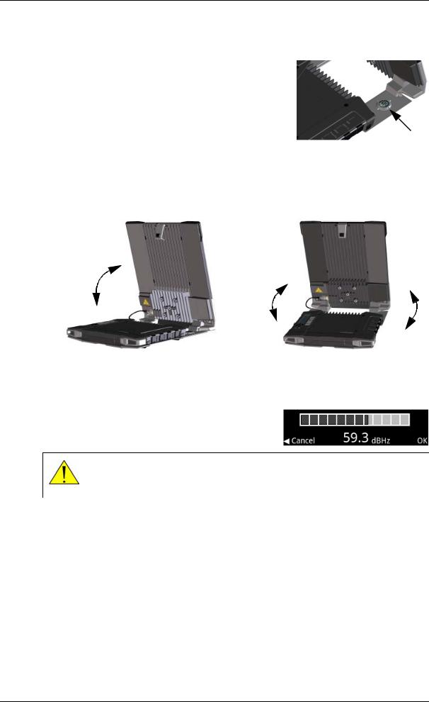
To point the antenna
To obtain optimum bandwidth and operating time, adjust the position of the antenna with great precision.
Do as follows:
1. If the terminal is not already in pointing mode, select
in the display and select Point now. |
Compass |
|
2.Use the compass to locate the approximate direction from the antenna front face to the satellite.
3.Slowly rotate and tilt the EXPLORER 710 antenna to find the highest possible signal strength.
Use the Draftdisplay and the pointing sound to guide you.
Remember that the mo e ccu tely the termin l is ligned, the better throughput and lower power consumption you will get!
4. Press OK on the display keypad when you have obtained the highest possible signal strength.
CAUTION! After accepting the signal strength, keep the minimum safety distance of 1 m from the antenna front face. The antenna may radiate microwave power as soon as the signal strength is accepted.
The EXPLORER 710 now starts to establish a connection to the BGAN network.
The registration procedure
The display shows the progress as follows:
•SEARCHING:
The EXPLORER 710 searches for the network operator. Note that the search procedure can be very short, so you may not see this text.
•REGISTERING:
The EXPLORER 710 is registering itself on the network.
If the GPS position has not yet been acquired at this point, the display may show NO GPS.
98-140012-DraftC1 |
Starting up the EXPLORER 710 |
17 |

Chapter 2: Getting Started
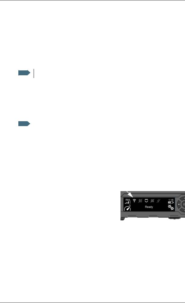
•READY (or other status information):
READY means the EXPLORER 710 is registered on the network and is ready to go online. If there is any other status information to show, e.g. if a call or data session is active or there is a warning, the display will show that instead.
Note By default, the EXPLORER 710 automatically connects to the Internet when you connect equipment to the LAN or WLAN interface (Standard data connection).
If you are not going to use the LAN/WLAN connection, remove the cable or disable the interface to avoid being charged for any transmission through this interface.
To repoint the antenna
You may need to point the antenna again later, e.g. if the terminal has been moved or the signal is blocked.
To startDraftthe pointing process again, do as follows:
Display: Select and select Point now. Then go hrough he pointing process as described in the previous section.
web interface: Select from the top right corner and select S art. Then go through the pointing process as described in the previous sec ion, but click Accept in the web interface instead of OK in the displ y.
Making the first call or d ta session
To make the first call
After connecting cables, ente ing the PIN and pointing the antenna, you are ready to make or receive the first call. The following sections provide a short guide to making calls. For more detailed information, see To make or receive a phone call with EXPLORER 710 on page 35.
For details on how to connect your phone, see
• To connect a phone using LAN or WLAN on page 31
• To connect an analogue phone on page 33
• To connect an ISDN phone or modem on page 34
To make a call from the EXPLORER 710
To make a call from a phone connected to the EXPLORER 710, dial
00 <country code> <phone number> followed by # or off-hook key.
Example: To call Cobham SATCOM in Denmark (+45 39558800) from an analogue phone, dial 00 45 39558800 #
98-140012-DraftC1 |
Making the first call or data session |
18 |
Chapter 2: Getting Started
To make a call to the EXPLORER 710
To make a call to a phone connected to the EXPLORER 710, dial
+ <Mobile number>
•+ is the prefix used in front of the country code for international calls.
•Mobile number: The mobile number of the EXPLORER 710 you are calling. The first part of the mobile number is always 870, which is the “country code” for the BGAN system. For information on your mobile numbers, refer to your airtime subscription.
Note There are two voice numbers, one for 3.1 kHz audio and one for Standard voice.
Example: If you are calling from Denmark and the mobile number for 3.1 kHz audio is 870782112345 on your EXPLORER 710, and you want to make a call to the EXPLORER 710 using 3.1 kHz audio, dial 00 870 782112345.
To make the firstDraftdata connection (WLAN)
To make the first data connection (LAN)
|
|
For the LAN interface to work wi hout any ur her se up, your computer must be set |
Note |
|
|
|
|
up to obtain an IP address and DNS server address au oma ically. |
Do as follows: |
||
1. |
Connect a LAN cable between your computer nd LAN#1 or LAN#2 on the EXPLORER 710. |
2. |
When power up and pointing is completed, St nd rd data connection is automatically |
|
established, if autom tic ctiv tion is en bled (def ult enabled). |
|
The status text in the display shows the active connection. |
To connect to the WLAN interface, do as follows:
1. Check that WLAN is enabled in your EXPLORER 710. The top line of the display shows which interfaces are enabled.
If WLAN is disabled, use the keypad arrows to highlight the WLAN icon and OK to enable WLAN.
98-140012-DraftC1 |
Making the first call or data session |
19 |
Loading...