

Page 1

User Manual
Release 02.11
ViBE VS7000
Convergent Video System
Page 2

Contacting Thomson Video Networks
2 ViBE VS7000
User Manual
Contacting Thomson Video Networks
http://www.thomson-networks.com/
Page 3

ViBE VS7000 3
User Manual
Contents
Preface ............................................................ 11
Chapter
1
Overview ......................................................... 17
Product Overview .................................................................. 18
Purpose ....................................................................................... 18
Main Features ............................................................................. 18
System Applications .................................................................. 19
Product Description............................................................... 20
Chassis ........................................................................................ 20
Overview ................................................................................ 20
Front Panel ............................................................................. 21
Rear Panel .............................................................................. 22
Chapter 2
Installation and Startup .................................. 25
Unpacking .............................................................................. 26
Mounting in Rack (Recommendations) ............................... 27
Ventilation................................................................................... 27
Cabling ........................................................................................ 27
Power Supply and Protective Ground ...................................... 27
Power Supply Cord(s) ........................................................... 27
Installing the Device (Steps) ................................................. 28
10RU and 6RU Devices .............................................................. 28
1RU Device.................................................................................. 28
Powering Up .......................................................................... 29
6RU and 10RU Devices Specificities......................................... 29
Performing the Initial Settings.............................................. 30
Preparing the Connection.......................................................... 30
Accessing the Web Interface for the First Time....................... 30
Checking the Nodes Status ....................................................... 30
Performing the IP Configuration ............................................... 31
Preparing the Definitive Connection......................................... 31
Establishing the Definitive Connection .................................... 32
Setting the Date and Time (Optional)....................................... 32
Page 4

Contents
4 ViBE VS7000
User Manual
Chapter 3
Web Browser Interface .................................... 35
Reaching the GUI.................................................................. 36
GUI Overview........................................................................ 37
General Organization................................................................. 37
Customizing the Display............................................................ 38
Resizing the Columns............................................................ 38
Sorting Elements in Arrays................................................... 38
Commonly Used Elements........................................................ 38
Status Pictograms ................................................................. 38
Other Pictograms................................................................... 39
Tables ..................................................................................... 39
Basic Settings........................................................................ 40
Creating a Job ............................................................................ 40
Launching a Job from a Workflow....................................... 40
Setting the Job Parameters .................................................. 42
Creating a Job Based on a Sample Workflow ......................... 43
Sample IP TV 1....................................................................... 43
Sample Web TV HLS 1 .......................................................... 46
Sample Web TV Smooth Streaming 1................................. 49
Sample Web TV Smooth Streaming 2................................. 51
Adapting a Sample Workflow ................................................... 53
List of Sample Workflows to Adapt ..................................... 53
Adapting a Sample Workflow (Steps) ................................. 54
Creating a Workflow .................................................................. 55
Introduction............................................................................ 55
Creating the Workflow .......................................................... 55
Adding Items to the Workflow ............................................. 56
Setting the Parameters of the Items .................................... 56
Publishing the Inputs and/or Outputs.................................. 56
Checking the Consistency..................................................... 57
Encoding a File ........................................................................... 57
Using a Hot Folder ..................................................................... 60
Configuring the Workflow .................................................... 60
Configuring the Hot Folder ................................................... 60
Using the Hot Folder ............................................................. 61
Configuring an SDI Input........................................................... 61
Naming the SDI Inputs.......................................................... 61
Using an SDI Input in a Workflow........................................ 61
Workflow Example With an SDI Input ................................. 61
Configuring an SDI System With a Matrix............................... 62
Declaring an SDI Matrix ........................................................ 62
Naming the Matrix’ Inputs.................................................... 64
Linking the SDI Inputs To the Matrix ................................... 65
Using the Matrix’ Inputs ....................................................... 65
Creating a Snapshot View ......................................................... 65
Creating a New Snapshot View............................................ 65
Creating a Snapshot View From a Workflow ...................... 67
Interface Description ............................................................ 68
System ........................................................................................ 68
Identity.................................................................................... 68
Page 5

Contents
ViBE VS7000 5
User Manual
Nodes...................................................................................... 68
IP ............................................................................................. 69
Hot Folder............................................................................... 72
SDI........................................................................................... 74
SNMP...................................................................................... 75
Date & Time ........................................................................... 75
User Accounts........................................................................ 76
Download ............................................................................... 77
Logs ........................................................................................ 78
Network Storage.................................................................... 81
Workflows ................................................................................... 82
Left Area ................................................................................. 82
Right Area............................................................................... 85
Jobs ............................................................................................. 96
Console ....................................................................................... 98
Snapshot ..................................................................................... 99
Logs ........................................................................................... 100
Purpose................................................................................. 100
Logs Array ............................................................................ 100
Filters and Sorting Options................................................. 101
Advanced.............................................................................. 102
Status Bar.................................................................................. 102
Workflow Library Content Parameters .............................. 104
Introduction .............................................................................. 104
Item Parameters Array ........................................................ 104
Input/Output......................................................................... 106
Common Parameters ............................................................... 107
Specific Parameters ................................................................. 109
Workflow Library: Inputs..................................................... 109
Workflow Library: Decoding ............................................... 114
Workflow Library: Preprocessing ....................................... 115
Workflow Library: Encoding ............................................... 124
Workflow Library: Outputs.................................................. 131
Workflow Library: Samples ................................................ 146
Tools ..................................................................................... 146
Chapter 4
Servicing ....................................................... 149
Adding a Diskless Node to Your System........................... 150
Configuring the BIOS of a Diskless Node............................... 150
For a blade: Accessing the BIOS ........................................ 150
For 1-RU Devices: Accessing the BIOS .............................. 154
Setting the BIOS Parameters.............................................. 154
Requesting a New License File ............................................... 160
Declaring a New License File .................................................. 161
Adding Options.................................................................... 162
Replacing a Diskless Node of your System....................... 163
Configuring the BIOS of the New Node ................................. 163
Replacing a Node ..................................................................... 163
Page 6

Contents
6 ViBE VS7000
User Manual
Chapter 5
Troubleshooting ............................................ 165
Troubleshooting Procedures ............................................. 166
Exporting Information for the Customer Support................. 166
Modifying a Workflow from a Text Editor.............................. 167
Exporting Logs ......................................................................... 167
Using the Console.................................................................... 167
Providing Remote Access to the ViBE VS7000 System ........ 167
Frequently Asked Questions.............................................. 168
Why cannot I instantiate my job
whereas there is space on the ViBE VS7000 system?........... 168
I do not see my workflow in the list
when I want to create a job. Why?.......................................... 168
I cannot create a workflow. Why?........................................... 168
I cannot create a job. Why? ..................................................... 168
When I want to launch a job, I get a "Job is waiting: license not
available" message. What should I do? ................................. 169
I cannot modify the system parameters. Why?..................... 169
I modified a workflow parameter, but it was not applied on the
currently running jobs. Why?.................................................. 169
Chapter 6
Customer Service .......................................... 171
Support Centers Contacts .................................................. 172
Warranty.............................................................................. 174
Services ............................................................................... 175
Spare Parts .......................................................................... 176
Returning an Equipment .................................................... 177
Repackaging for Shipment ................................................ 178
Long Term Product Support .............................................. 179
Recycling the Product......................................................... 180
Chapter 7
Tools ............................................................. 181
Equipment Setup ................................................................ 182
Overview................................................................................... 182
Operation .................................................................................. 182
Launching the Equipment Setup........................................ 182
Connecting to a Device ....................................................... 183
Setting the Device Parameters ........................................... 185
HP Monitoring Tools (6RU and 10RU Devices) ................ 186
Connecting to the HP Monitoring Tools................................. 186
Method #1: Connecting via the iLO Port in DHCP............. 186
Method #2: Connecting on the DHCP Network
using the IP Address of the Device .................................... 187
Page 7

Contents
ViBE VS7000 7
User Manual
Method #3: Connecting After Configuring Manually
the IP Address of the Device............................................... 188
Performing the IP Configuration from the HP Interface........ 190
Accessing the Interconnect Bays’ Management Console 190
Configuring the Interconnect Bays..................................... 192
Saving your Configuration.................................................. 192
More Information................................................................. 193
Appendix A
Technical Specifications ............................... 195
Specifications....................................................................... 196
Electrical, Thermal and Mechanical Specifications ............... 196
VS7000 10RU........................................................................ 196
VS7000 6RU.......................................................................... 205
VS7000 1RU.......................................................................... 209
Inputs Specifications................................................................ 210
Live Inputs ............................................................................ 210
SDI Inputs ............................................................................. 210
File Formats.......................................................................... 211
Decoding Specifications .......................................................... 211
Audio Decoding ................................................................... 211
Video Decoding.................................................................... 212
Processing Specifications........................................................ 212
Video Processing ................................................................. 212
Audio Processing................................................................. 213
Encoding Specifications .......................................................... 213
Audio Encoding ................................................................... 213
Video Encoding.................................................................... 215
Outputs Specifications............................................................. 216
Live Output........................................................................... 216
File Output............................................................................ 218
Latency ................................................................................. 219
Blade Center Physical Interfaces Specifications .................... 219
Control-Command Specifications........................................... 219
Standard Compliance.......................................................... 221
Ordering Guide .................................................................... 223
Appendix B
SNMP Management ....................................... 229
MIB Description ................................................................... 230
Trap Descriptions ..................................................................... 231
Register/Unregister a Manager to Receive the Traps ........... 233
Get the Active Log List or the Closed Log List....................... 234
Registering SNMP Manager on the GUI............................ 235
Enabling HP Blade Center SNMP Agent............................ 236
Page 8

Contents
8 ViBE VS7000
User Manual
Appendix C
Safety Instructions ....................................... 237
Appendix
D
Regulatory Notices ....................................... 239
Appendix
E
Logs .............................................................. 241
Logs Categories .................................................................. 242
List of Logs .......................................................................... 243
Appendix F
Network Settings (6RU and 10RU Devices) .. 249
Blades .................................................................................. 250
Internal Switches (Flex10) ....................................................... 250
Interfaces Bonding ................................................................... 250
10RU Device......................................................................... 250
6RU Device........................................................................... 250
VLAN Tagging...................................................................... 251
Internal Switches & Software Configuration Consistency 252
Flex10................................................................................... 253
External Connectors Description ............................................ 253
Grouping Possibilities.............................................................. 253
Detailed Factory Network Configuration................................ 253
Flex10 Configuration................................................................ 256
How to Use a Configuration File? ...................................... 256
Description of the Configuration Files ............................... 256
Redundancy Schemes........................................................ 258
Internal LAN.............................................................................. 258
External LAN............................................................................. 258
Multicast Management ...................................................... 260
Multiple Blade Centers Configuration............................... 261
Interfaces Bitrates ............................................................... 263
Bitrates Allocation on 10-RU Interfaces.................................. 263
Bitrates Allocation on 6-RU Interfaces.................................... 263
Bitrates Allocation Rules.......................................................... 263
HP Documentation.............................................................. 264
Appendix G
Network Settings (1RU Devices) ................... 265
Network Configuration....................................................... 266
Page 9

Contents
ViBE VS7000 9
User Manual
Glossary ........................................................ 267
Index ............................................................. 273
Page 10

Contents
10 ViBE VS7000
User Manual
BLANK PAGE
Page 11

ViBE VS7000 11
User Manual
Preface
Standard Documentation Set
The ViBE VS7000 documentation set consists of:
A User Manual
A Quick Start Guide
A Web Services SOAP API Getting Started document
The ViBE VS7000 User Manual contains background information about
the ViBE VS7000 Convergent Video System, and describes operating
procedures. This manual can be used while learning about ViBE VS7000,
and for enhancing your basic knowledge of the product.
The ViBE VS7000 Quick Start Guide contains information about installing
and configuring the equipment.
The ViBE VS7000 Web Services SOAP API documentation provides you
with the basic information you need to use the product’s SOAP API.
Software Version
This manual covers the functionality of the software version 02.11 of the
ViBE VS7000 product.
This manual continues to be relevant to subsequent software versions
where the functionality of the equipment has not changed. When a new
software version changes the functionality of the product, a new version
of this manual is provided.
About this Manual
This manual is written for Operators of the ViBE VS7000.
This manual should be kept in a safe place for reference for the life
time of the equipment. If passing the equipment to a third party,
please ensure to pass all relevant documentation including this
manual.
Page 12

Preface — Conventions Used in This Manual
12 ViBE VS7000
User Manual
The manual is organized into the following chapters and appendices:
Chapter 1 ’Overview’
gives a general description of the equipment
and its main features.
Chapter 2 ’Installation and Startup’
provides the procedures
required for device installation and initial configuration, and describes
how to connect the device to other devices in your system.
Chapter 3 ’Web Browser Interface’
details how to use the Web
Browser Graphical User Interface.
Chapter 4 ’Servicing’
describes how to add or replace nodes of your
system, and how to add options.
Chapter 5 ’Troubleshooting’
describes the procedure to follow when
you face any problem with the equipment.
Chapter 6 ’Customer Service’
provides you with the customer
service contacts and information on how to return a product.
Chapter 7 ’Tools’
describes the
Equipment Setup
tool delivered on
the CD-ROM with the product.
Appendix A ’Technical Specifications’
gives specifications of the
device, device compliance, declarations of conformity and ordering
guide to order the device and its options.
Appendix B ’SNMP Management’
explains how to set the SNMP
community string and the access rights. You will also find MIB
description, how to register the SNMP Manager on the VS7000
Graphical User Interface etc.
Appendix C ’Safety Instructions’
gives instructions related to risk of
fire, electric shock or injury to persons. This important section is
available in English, German and French versions.
Appendix D ’Regulatory Notices’
provides device compliances.
Appendix E ’Logs’
gives the list of alarms visible in the Logs panel of
the GUI (XML file).
A
’Glossary’
can be found at the end of the manual just prior the
’Index’
.
Conventions Used in This Manual
Warnings, Cautions and Notes
Heed Warnings
All warnings on the product and in the operating instructions should be
adhered to. The manufacturer cannot be held responsible for injuries or
damages where warnings and cautions have been ignored or taken
lightly.
Page 13
Preface — Conventions Used in This Manual
ViBE VS7000 13
User Manual
Read Instructions
All the safety and operating instructions should be read before this
product is operated.
Follow Instructions
All operating and use instructions should be followed.
Terms in this Manual
Safety-related statements appear in this manual in the following form:
Warning statements identify conditions or practices that may result
in personal injury or loss of life.
Caution statements identify conditions or practices that may result in
damage to equipment or other property, or which may cause
equipment crucial to your business environment to become
temporarily non-operational.
Notes provide supplementary information. They are highlighted for
emphasis, as in this example, and are placed immediately after the
relevant text.
Page 14

Preface — Documentation Feedback
14 ViBE VS7000
User Manual
Formatting
Naming conventions for the interface elements and Windows elements
in this manual follow the Microsoft Manual of Style, Third Edition.
Naming conventions for MPEG-2, ATSC, and DVB structures follow the
conventions derived from the standards documents listed in
Appendix A ’Technical Specifications’
. In addition, the following
formatting conventions apply to this manual:
Pale blue text refers to specific interface elements that you are
instructed to select, click, or clear.
Example: “Select Settings from the Configuration menu”.
Blue-Green text refers to document names, sections, figures or tables.
Example: “Refer to Section ’Warnings, Cautions and Notes’ on page
13 for more information”.
Mono-spaced
text can indicate the following:
Text you enter from a keyboard
Example: “Enter
administrator
for your login and
administrator
for your password”.
Paths to components on your hard drive
Example: “The MIB is at the following location:
C:\MIB
”.
Documentation Feedback
We are taking great care of our publications. Please help us to improve
them by sending your feedback with the reference of the manual at the
email address:
Email: techpubs@thomson-networks.com
Important Notice
Thomson Video Networks reserves the right to make corrections,
modifications, enhancements, improvements and other changes to its
products or services at any time and to discontinue any product or
service without notice.
Page 15

Preface — Trademarks
ViBE VS7000 15
User Manual
Trademarks
Copyrights
© Copyright 2012 Thomson Video Networks. All rights reserved.
Dolby and the double-D symbol are registered
trademarks of Dolby laboratories.
Supply of this Implementation of Dolby technology
does not convey a license nor imply a right under any
patent, or any other industrial or intellectual property
right of Dolby Laboratories, to use this
Implementation in any finished end-user or
ready-to-use final product. It is hereby notified that a
license for such use is required from Dolby
Laboratories.
MPEG-2 / MPEG-4 AAC audio encoding technology is
authorized by the Fraunhofer IIS license
(
http://www.iis.fraunhofer.de/amm/
).
Thomson is a trademark of Technicolor S.A.
All other tradenames referenced are service marks, trademarks, or registered
trademarks of their respective companies.
Page 16

Preface — Copyrights
16 ViBE VS7000
User Manual
BLANK PAGE
Page 17

ViBE VS7000 17
User Manual
Chapter 1
Overview
Introduction
This chapter gives a general description of the equipment and its main
features.
In this Chapter
’Product Overview’
...................................................................... page 18
’Product Description’
...................................................................page 20
Page 18

Chapter 1 ’Overview’ — Product Overview
18 ViBE VS7000
User Manual
Product Overview
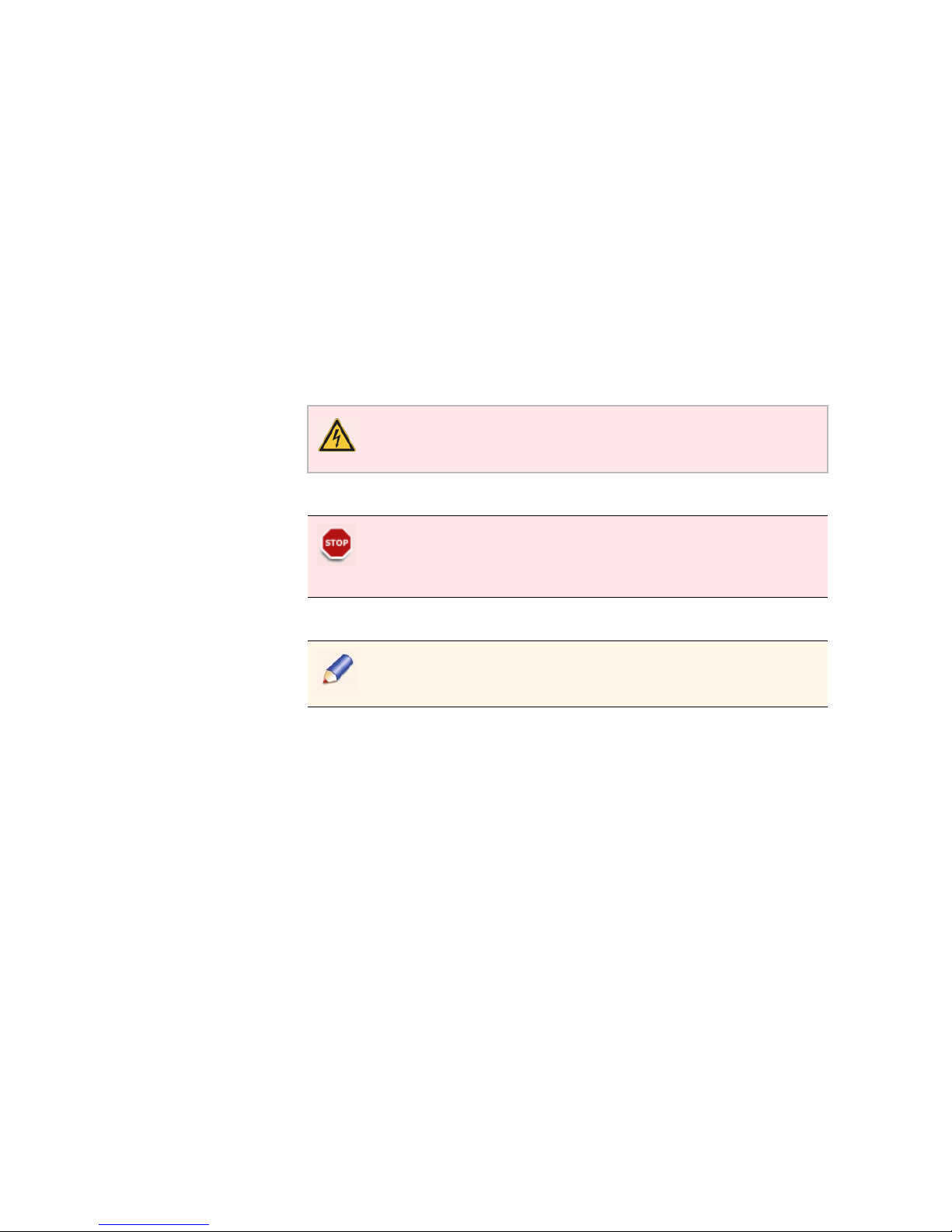
The Thomson Video Networks ViBE VS7000 Video System is a
fully-integrated video solution tailored for all new convergent
applications such as Web TV and Over-The-Top (OTT) service delivery, as
well as traditional IPTV and IP/Cable delivery.
Purpose
The ViBE VS7000 provides a flexible way to design workflows. The
Workflow Builder allows the creation of live, file-based and mixed
workflows, for any kind of network.
Combining all the major audio/video codecs and the latest adaptive
streaming formats, the ViBE VS7000 provides a unique answer to IPTV
delivery, Mobile 3G/4G, Web TV streaming and OTT services
broadcasting.
Simplicity: one unique graphical user interface lets you control and
monitor hundreds of channels simultaneously. With built-in 10GigE
switches, racking and cabling nightmares vanish.
Reliability: built around highly resilient IT platforms equipped with
hot-swappable, redundant components, the ViBE VS7000 provides
native load-balancing and system redundancy to avoid downtime.
Scalability: from a single-server to multi-blade systems, the ViBE VS7000
is designed to scale and grow with your business.
Flexibility: the ViBE VS7000 allows heterogeneous architectures (SDI and
IP inputs) and simultaneous live and off line encoding.
Main Features
Best-in-class video quality
Support of multiple video/audio codecs
Support of MPEG transport stream
Adaptive Bit Rate:
Adobe Flash
Apple HTTP Live Streaming
Microsoft Smooth Streaming
MPEG-DASH
Video resolution up to 1920 x 1080
Progressive and interlaced modes
Multiple output formats per channel
Page 19
Chapter 1 ’Overview’ — Product Overview
ViBE VS7000 19
User Manual
Scalable number of input channels
Scalable number of output profiles
Advanced video and audio pre-processing
Integrated content protection
HTTP Centralized Operation
Workflow Builder
SOAP/Web services for external interfacing
Integrated load balancing and failover
IPV4 support
SDI/HD-SDI and router management
System Applications
Figure 1-1. System applications
Page 20

Chapter 1 ’Overview’ — Product Description
20 ViBE VS7000
User Manual
Product Description
Chassis
Overview
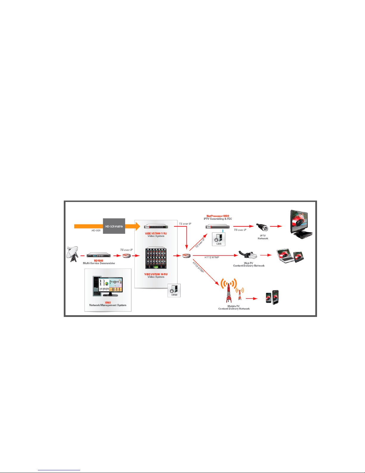
The ViBE VS7000 product is proposed on three chassis: 1RUx19”,
6RUx19”, or 10RUx19”.
Physical characteristics are as follows:
Hot swappable power supplies
Hot swappable fans
Hot swappable processing units
Hot swappable IP switches
Cooling: front-rear airflow
For more information on the specifications, refer to
Appendix A
’Technical Specifications’
on page 195.
The sections below show the front and real panels of the devices. For a
full description of the device, refer to the HP documentation:
For a 1-RU device, see:
G7:
h18000.www1.hp.com/products/quickspecs/13598_div/13598_div.pdf
Gen8:
h18000.www1.hp.com/products/quickspecs/14211_na/14211_na.pdf
For a 6-RU server, see:
http://h18000.www1.hp.com/products/quickspecs/12790_div/1279
0_div.html
For a 10-RU server, see:
http://h18000.www1.hp.com/products/quickspecs/12810_div/1281
0_div.html
Page 21
Chapter 1 ’Overview’ — Product Description
ViBE VS7000 21
User Manual
Front Panel
Figure 1-2. ViBE VS7000 front panel of the 10-RU server
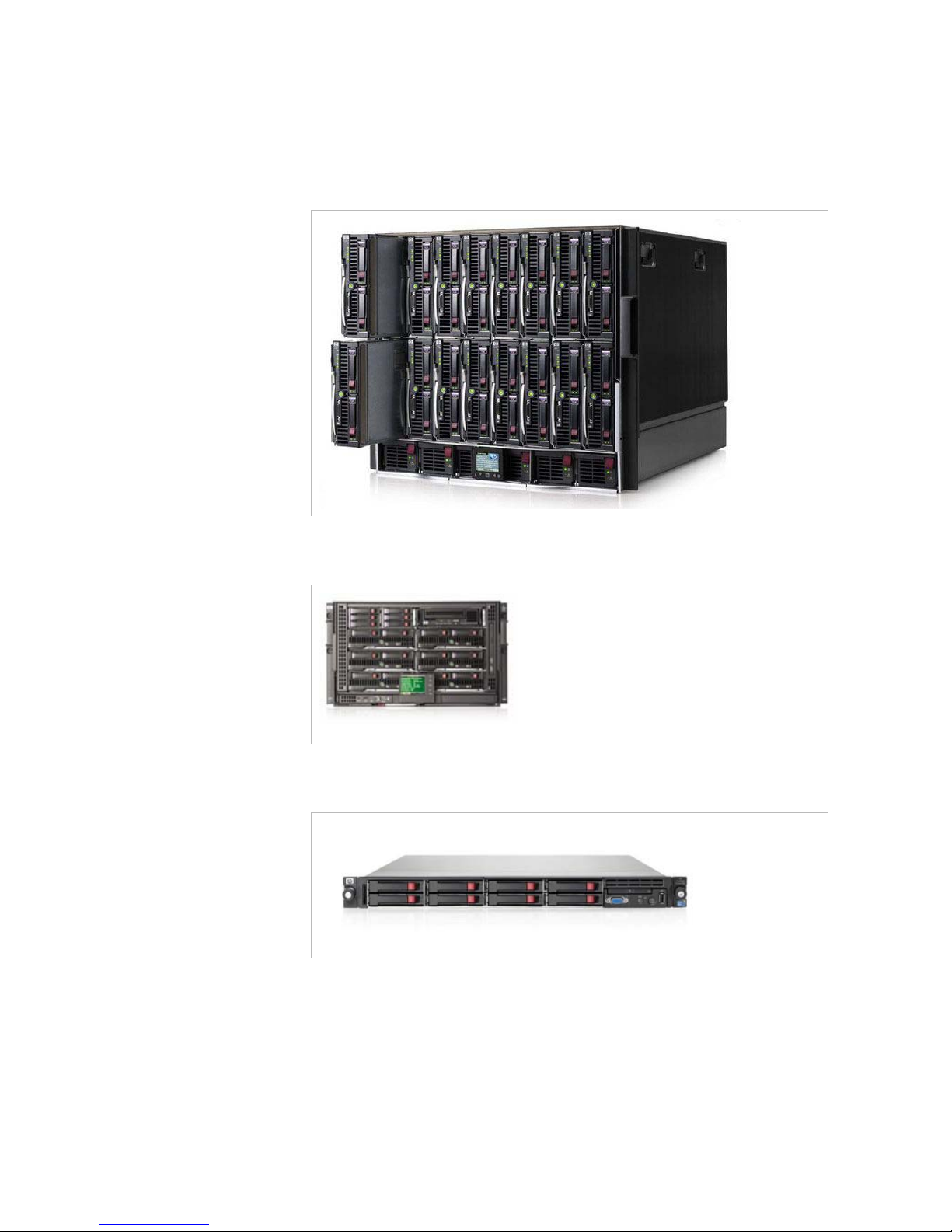
Figure 1-3. ViBE VS7000 front panel of the 6-RU server
Figure 1-4. ViBE VS7000 front panel of the 1-RU server
Page 22
Chapter 1 ’Overview’ — Product Description
22 ViBE VS7000
User Manual
Rear Panel
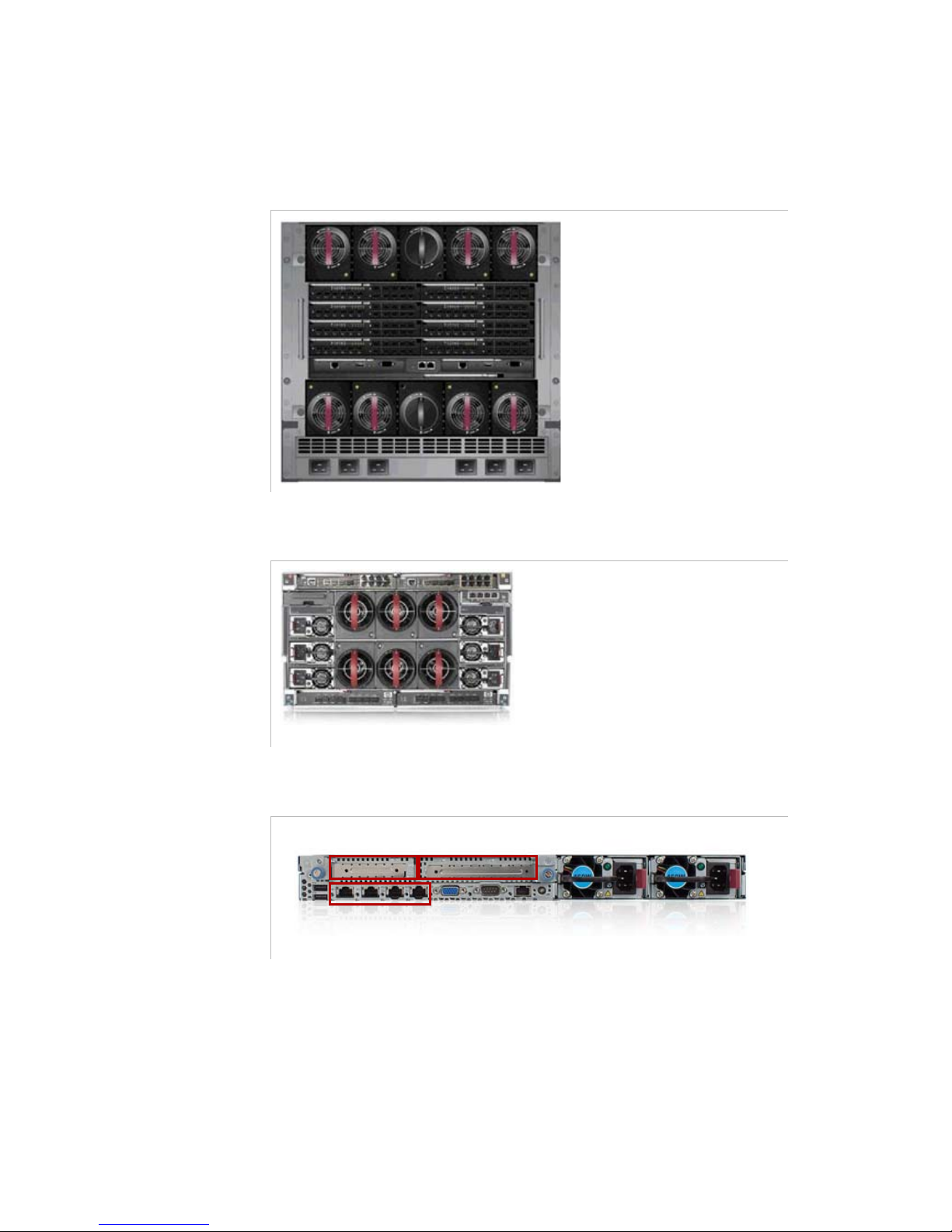
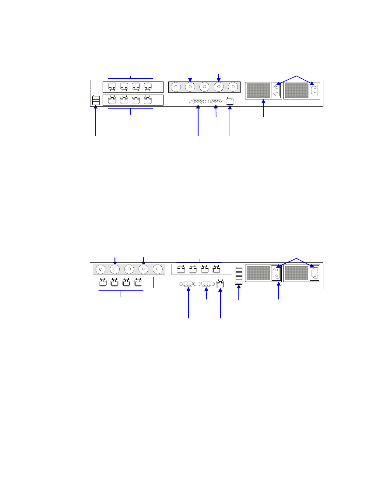
Figure 1-5. ViBE VS7000 rear panel of the 10-RU server
Figure 1-6. ViBE VS7000 rear panel of the 6-RU server
Figure 1-7. ViBE VS7000 rear panel of the 1-RU server
Depending on your server, the content of the slots may vary:
On a G7 server:
Slot 0: 4 Ethernet interfaces
Slot 1: optional additional Ethernet card
Slot 2: optional SDI card
slot 1
slot 2
slot 0
Page 23
Chapter 1 ’Overview’ — Product Description
ViBE VS7000 23
User Manual
Figure 1-8. Rear panel connector of the G7 1-RU server
On a G8 server:
Slot 0: 4 Ethernet interfaces
Slot 1: optional SDI card
Slot 2: optional additional Ethernet card
Figure 1-9. Rear panel connector of the Gen8 1-RU server
VGA
output
Serial/
COM port
Network connectors
1 to 4
iLO port
Power supply
connectors
(not used)
Optional additional network
connectors (5 to 8)
Optional
redundant power
supply unit
USB connectors
(not used)
SDI board (optional)*:
IN1 IN2
* Other connectors are not used.
VGA
output
Serial/
COM port
Network connectors
4 to 1
iLO port
Power supply
connectors
(not used)
Optional additional network
connectors (8 to 5)
Optional
redundant power
supply unit
USB
connectors
SDI board (optional)*:
IN2 IN1
* Other connectors are not used.
Page 24

Chapter 1 ’Overview’ — Product Description
24 ViBE VS7000
User Manual
BLANK PAGE
Page 25
ViBE VS7000 25
User Manual
Chapter 2
Installation and Startup
Introduction
This chapter
provides the procedures required for device installation
and initial configuration and describes how to connect the device to
other devices in your system
.
In this Chapter
’Unpacking’
...................................................................................page 26
’Mounting in Rack (Recommendations)’
................................. page 27
’Installing the Device (Steps)’
....................................................page 28
’Powering Up’
............................................................................... page 29
’Performing the Initial Settings’
................................................page 30
Read and follow the important safety information in Section
’Safety Instructions’
on page 237
, noting especially those
instructions related to risk of fire, electric shock or injury to
persons.
Page 26

Chapter 2 ’Installation and Startup’ — Unpacking
26 ViBE VS7000
User Manual
Unpacking
Tab le 2 -1
lists the accessories that are always shipped with your device.
Use this list to ensure that your order is complete.
More accessories can be delivered depending on options you chose.
Table 2-1. List of accessories delivered with the device
Quantity Description
n
ViBE VS7000 blade center or server: 10RU, 6RU or 1RU
n
Bays (if the device is a blade center)
n
Ethernet connectors (if the device is a blade center)
n
Power cords
1
Cable to connect a screen, a keyboard and a mouse to a bay (if
the device is a blade center)
1
CD-ROM
Page 27
Chapter 2 ’Installation and Startup’ — Mounting in Rack (Recommendations)
ViBE VS7000 27
User Manual
Mounting in Rack (Recommendations)
Rack mounting is not mandatory for ViBE VS7000 but the ventilation and
safety requirements given in this section must be observed in all cases.
Ventilation
Please refer to the recommendations provided by HP.
Cabling
It is essential to separate the power supply cables from the signal cables.
When facing the rear of the rack (as the device is connected via the rear
panel), the power supply cables must be guided to the right of the chassis
and the signal cables to the left.
Power Supply and Protective Ground
Power Supply Cord(s)
Specifications
The AC mains power cords are only shipped with the device if ordered.
For DC supply units, use power cords suitable with the HP specifications.
Connecting AC Mains Power Supply Cord(s)
Power Supply End
The connection panel should comply with the legislation in force in the
country of installation. The connection panel must be positioned in the
rack in such a way that the plug and power cord(s) are within easy reach
for switching off purposes.
For (each) mains inlet, the wiring system must feature overload and earth
fault protection and a bipolar cut-off device or a differential circuit
breaker. If in doubt, contact a qualified electrician.
ViBE VS7000 End
Plug the power cord(s) into the mains inlet.
Never supply a power supply unit which is not in the chassis.
The built-in overload protection cannot be accessed or reset.
Page 28
Chapter 2 ’Installation and Startup’ — Installing the Device (Steps)
28 ViBE VS7000
User Manual
Installing the Device (Steps)
Depending on the type of device, follow the steps below to install the
device and perform its initial configuration.
10RU and 6RU Devices
1.
Install the blade center at its definitive place.
2.
On the front panel, install the blades in the blade center: the blades
and the bays in the blade center are numbered (stickers). Insert
blade #1 in bay #1, blade #2 in bay #2, etc.
3.
Install the power supply units.
1RU Device
Mount the device in a rack.
If you need to move the blade center, it must be empty.
Page 29

Chapter 2 ’Installation and Startup’ — Powering Up
ViBE VS7000 29
User Manual
Powering Up
Connect the power cord(s). The green
POWER
LED comes on.
6RU and 10RU Devices Specificities
If needed, configure the power supply management (refer to the HP
Blade System Enclosure Setup and Installation Guide that corresponds to
your system, provided on the CD-ROM).
On the first start-up, use the front panel screen to check the status of the
equipment. To do so:
1.
Press OK to activate the display.
2.
Select Health Summary from the menu.
3.
Check that all indicators are green.
Check that ViBE VS7000 is not yet connected to a LAN. Indeed,
factory-set IP addresses may cause disturbance (address conflict) on
the LAN when ViBE VS7000 is switched on. For more information,
see
Section ’Detailed Factory Network Configuration’
on page 253.
Page 30
Chapter 2 ’Installation and Startup’ — Performing the Initial Settings
30 ViBE VS7000
User Manual
Performing the Initial Settings
Preparing the Connection
1.
Connect the Private System LAN of all the platforms composing the
ViBE VS7000 to a single GiGE switch:
For blade centers: insert an SFP coupler on interface x1 of the
first internal switch of the blade center, and connect it to the
GigE switch.
For 1RU servers: connect the NIC 1 to the GigE switch.
2.
Connect a PC in DHCP on the GigE switch.
Accessing the Web Interface for the First Time
To access the Web interface, proceed as follows:
1.
Open a Web browser.
2.
Type t h e
192.168.250.9
IP address in the address bar and press
Enter.
3.
Use the following account information:
Login:
admin
Password:
admin
If you cannot connect to the
192.168.250.9
IP address, which might
happen if the factory-set IP address has been modified, use the Discover
feature of the equipment set-up tool. See Chapter 7 ’Tools’
on page 181
.
Checking the Nodes Status
1.
Select the System tab.
2.
Go to the Nodes category.
3.
Check that:
All nodes present in the device are displayed in the list in the
GUI.
The status of each node is OK.
Gigabit copper couplers are not fast-Ethernet compliant. Make sure
you use a device that is able to process Gigabit.
The GigE switch shall be isolated from your network, as the presence
of a DHCP server could cause conflicts.
Page 31

Chapter 2 ’Installation and Startup’ — Performing the Initial Settings
ViBE VS7000 31
User Manual
Performing the IP Configuration
1.
Select the System tab.
2.
Go to the IP category.
3.
Set the
Control
(X6 on 6RU and 10RU devices) network on your
control/command network:
If there are n nodes in the system, you need n consecutive
addresses, plus one for supervision.
Set the following parameters:
-
Address
-
Mask
-
Gateway (optional)
-
First address: first address of the n consecutive addresses
-
Supervision address
4.
Set the
Data 1
(X2 on 6RU and 10RU devices) network on your data
network:
If there are n nodes in the system, you need n consecutive
addresses.
Set the following parameters:
-
Address
-
Mask
-
Gateway (optional)
-
First address: first address of the n consecutive addresses
5.
Click Apply.
Preparing the Definitive Connection
Once you have made your IP configuration from the GUI:
1.
Disconnect the supervision PC from the GigE switch.
Page 32

Chapter 2 ’Installation and Startup’ — Performing the Initial Settings
32 ViBE VS7000
User Manual
2.
Depending on the composition of your ViBE VS7000:
For a stand-alone blade server:
a.
Remove the SFP coupler from interface x1.
b.
Insert an SFP coupler on interfaces x6 and x2 of the two internal
switches of the blade center.
c.
Connect interfaces x6 on your control-command network, on
one unique switch or on two switches if they are redunded.
d.
Connect interfaces x2 on your data network, on one unique
switch or on two switches if they are redunded.
If your
ViBE VS7000 contains several 10RU blade centers, connect
them using specific stacking cables. Refer to
Appendix F ’Multiple
Blade Centers Configuration’
on page 261.
For 1RU devices:
a.
Connect interface 3 to your control-command network.
b.
Connect interface 4 to the data network.
Establishing the Definitive Connection
1.
From a supervision PC connected on your control-command network,
open a Web browser.
2.
Type in the address bar the supervision IP address that you configured
earlier and press Enter.
3.
Use the following account information:
Login:
admin
Password:
admin
Setting the Date and Time (Optional)
1.
Select the System tab.
2.
Go to the Date & time category.
3.
Choose the method that should be used to get the UTC:
Fix it manually: enter the date and time in the UTC date and time
field.
Get it from one or several NTP servers: add the IP address(es) of
the server(s) to the NTP synchronized list.
You could perform the operation on one
internal switch of the
blade center
only but there would be no redundancy.
Page 33

Chapter 2 ’Installation and Startup’ — Performing the Initial Settings
ViBE VS7000 33
User Manual
4.
Choose the time zone to use from the drop-down list.
5.
Indicate if you want to adjust the time automatically for Daylight
Saving Time.
Figure 2-1. Date and time settings
6.
Click Apply.
Page 34

Chapter 2 ’Installation and Startup’ — Performing the Initial Settings
34 ViBE VS7000
User Manual
BLANK PAGE
Page 35

ViBE VS7000 35
User Manual
Chapter 3
Web Browser Interface
Introduction
This chapter explains how to use the Web Browser Graphical User
Interface to configure the equipment.
In this Chapter
’Reaching the GUI’
....................................................................... page 36
’GUI Overview’
............................................................................. page 37
’Basic Settings’
............................................................................. page 40
’Interface Description’
.................................................................page 68
’Workflow Library Content Parameters’
.................................. page 104
Page 36

Chapter 3 ’Web Browser Interface’ — Reaching the GUI
36 ViBE VS7000
User Manual
Reaching the GUI
You can run the ViBE VS7000 GUI provided you observe the following
requirements for your personal computer:
INTEL-Based PC (at least Pentium 1 GHz with 512 Mbytes of memory)
running Windows XP or Windows 7.
Web browser must be Internet Explorer 7.0 (or higher) or Mozilla
Firefox 3.0 (or higher).
Java Runtime Environment 2.0 or higher must be installed on client
PC. If not present, install the Java
TM
2 Standard Edition Runtime
Environment on your supervision computer. The installation software
is on the CD-ROM that has been supplied with your ViBE VS7000
equipment.
The Graphical User Interface (GUI) is a Java applet. To launch it:
1.
Open a Web browser.
2.
Type the equipment IP address in the address bar and press Enter.
3.
Use the following account information:
Login:
admin
Password:
admin
This is the default factory account. With administrator rights, you can
change the password at your convenience.
Page 37

Chapter 3 ’Web Browser Interface’ — GUI Overview
ViBE VS7000 37
User Manual
GUI Overview
This section describes the general organization of the graphical user
interface and its main components. The display may vary depending on
the rights of the connected user.
General Organization
The graphical user interface is divided into three main areas, shown in
Figure 3-1
.
Figure 3-1. Graphical user interface overview
The GUI contains the following areas:
A Snapshot view, on the left, that shows the content of inputs in a tree.
A main area from where you can perform configuration and
monitoring. This area contains several tabs. Click them to navigate in
the GUI.
A Logs panel that shows the logs that are raised on the equipment.
A status bar that provides information on the equipment status, the
date and time, etc.
Status bar
Main area
Logs panel
Snap-
shot
view
Page 38

Chapter 3 ’Web Browser Interface’ — GUI Overview
38 ViBE VS7000
User Manual
Customizing the Display
Resizing the Columns
In arrays, columns can be resized. Move your mouse cursor between two
header columns. The mouse cursor should change to . Click and drag
the column to the desired size, and then release the mouse button.
Sorting Elements in Arrays
In any array, you can sort elements by any column. To do so, click the
header column once. A white arrow appears in this header.
To change the sorting mode, click the header once more. When sorted in
increasing order, the arrow is displayed. In decreasing order, the
arrow is shown.
Commonly Used Elements
Some elements are recurrent in the GUI, as pictograms for instance.
These elements are described here.
Status Pictograms
Ta bl e 3 -1
lists the status pictograms used in the GUI.
Table 3-1. Status pictograms
Status icon Meaning
OK
Information message
Warni ng
Minor error
Major error
Critical error
Page 39

Chapter 3 ’Web Browser Interface’ — GUI Overview
ViBE VS7000 39
User Manual
Other Pictograms
Tables
The GUI contains numerous tables. In some of them, it is possible to
modify the content.
To add an item to a list, click the button.
To remove an item from a list, select a line and click the button.
To modify a value in a table, double-click the corresponding cell and type
the new value or if it is a list, select a value from the list. In some lists, it
is also possible to add values. For instance, in a
TS audio video
extractor
item, you can leave the PMT PID to Auto or enter your own
value.
Figure 3-2. Example of editable drop-down list
Table 3-2. Pictograms
Pictogram Meaning Behaviour
Add Adds an item to a list.
Remove Removes a selected item from a list.
Edit Edits a parameter.
Search Indicates a search field.
Page 40

Chapter 3 ’Web Browser Interface’ — Basic Settings
40 ViBE VS7000
User Manual
Basic Settings
Creating a Job
To create a job, follow the procedures below.
Launching a Job from a Workflow
1.
Click the Jobs tab.
Figure 3-3. Opening the Jobs tab
2.
Click Create.
Figure 3-4. Creating a job
Page 41

Chapter 3 ’Web Browser Interface’ — Basic Settings
ViBE VS7000 41
User Manual
3.
In the list, select a workflow. The description on the right may help you
to choose a workflow.
Figure 3-5. Choosing the workflow on which to base the job
Page 42

Chapter 3 ’Web Browser Interface’ — Basic Settings
42 ViBE VS7000
User Manual
4.
Click Ok.
Setting the Job Parameters
The list of parameters that you must set to create the job is displayed.
Figure 3-6. Setting the job parameters
1.
Fill in the Name field on the left. This name will later appear in the list
of jobs. Choose this name carefully so that you are able to recognize
it easily in the list, as there may be a high number of jobs in the list.
2.
For an offline job, you can set a priority for the job and its speed:
Priority: if there are not enough resources (CPU, memory...) to
process all the jobs, and if you want this particular job to be
processed before the others, set an important priority (between
1 and 250; 250 being the highest priority). The other jobs will be
processed more slowly.
Speed: if set to 1, the job will last at most as long as the video
duration. If set to
2
, the job will last at most half as long as the
video duration, etc.
Note that if the network bitrate is too low, the speed goal might
not be respected.
If not configured, the job will get the available resources of the
most available node.
Note that a live job always holds priority over offline jobs. If there are
not enough resources, the transcoding is kept in
waiting
state until
resources become available.
Page 43

Chapter 3 ’Web Browser Interface’ — Basic Settings
ViBE VS7000 43
User Manual
3.
In the array, double-click the cells in the Val u e column to enter your
values. If you need details on the parameters, refer to section
Section
’Workflow Library Content Parameters’
on page 104.
4.
Click Create.
The job is displayed in the
Jobs list
. Check its status and its state.
For more information on the
Jobs
tab, see
Section ’Jobs’
on page 96.
Creating a Job Based on a Sample Workflow
Sample workflows are provided with the ViBE VS7000 equipment. To use
them, proceed as described in
Section ’Creating a Job’
on page 40
above.
When selecting a sample workflow from the list of workflows, you have
to set a number of parameters before launching the job. These
parameters are split into different tabs.
Browse the tabs and set the parameters shown in the figures.
Once you are done, click
Create
.
Sample IP TV 1
The
Sample IP TV 1
workflow generates an IP TV MPEG-2 transport
stream.
The source is a program issuing from a TS over IP stream.
The video is transcoded into H.264. Audio components can be
transcoded or sent in pass-through mode. Other components are sent in
pass-through mode.
The output stream is TS over UDP/IP or TS over RTP/UDP/IP.
The figures below show the different tabs and parameters to set in the
Sample IP TV 1
workflow.
Figure 3-7. Sample IP TV 1 workflow – Input TS tab
If you need details on the parameters, refer to
Section ’Workflow
Library: Inputs’
on page 109.
Page 44

Chapter 3 ’Web Browser Interface’ — Basic Settings
44 ViBE VS7000
User Manual
Figure 3-8. Sample IP TV 1 workflow – Video, Processing, Encoding tab
If you need details on the parameters, look for the video subsections in
Section ’Workflow Library: Preprocessing’
on page 115 and
Section
’Workflow Library: Encoding’
on page 124.
Page 45

Chapter 3 ’Web Browser Interface’ — Basic Settings
ViBE VS7000 45
User Manual
Figure 3-9. Sample IP TV 1 workflow – Audio tab
If you need details on the parameters, look for the audio subsections in
Section ’Workflow Library: Preprocessing’
on page 115 and
Section
’Workflow Library: Encoding’
on page 124.
Figure 3-10. Sample IP TV 1 workflow – Output TS tab
If you need details on the parameters, refer to
Section ’Workflow
Library: Outputs’
on page 131.
Page 46

Chapter 3 ’Web Browser Interface’ — Basic Settings
46 ViBE VS7000
User Manual
Figure 3-11. Sample IP TV 1 workflow – Pass-through component tab
Sample Web TV HLS 1
The
Sample Web TV HLS 1
workflow generates an HLS output.
The input is a TS file or a TS over IP input. A program is transcoded
(audio and video), the chunks are generated and may be encrypted, and
are then available on the local Web server.
The figures below show the different tabs and parameters to set in the
Sample Web TV HLS 1
workflow.
Input, Audio, Video, DRM and Output Parameters
Figure 3-12. Sample Web TV HLS 1 workflow – Input TS tab
If you need details on the parameters, refer to
Section ’Workflow
Library: Inputs’
on page 109.
Figure 3-13. Sample Web TV HLS 1 workflow – Video tab
If you need details on the parameters, refer to
Section ’Workflow
Library: Decoding’
on page 114 and
Section ’Workflow Library:
Preprocessing’
on page 115.
Page 47

Chapter 3 ’Web Browser Interface’ — Basic Settings
ViBE VS7000 47
User Manual
Figure 3-14. Sample Web TV HLS 1 workflow – Output HLS tab
If you need details on the parameters, refer to
Section ’HLS Output’
on
page 134.
Figure 3-15. Sample Web TV HLS 1 workflow – DRM tab
If you need details on the parameters, refer to
Section ’HLS Output’
on
page 134.
Figure 3-16. Sample Web TV HLS 1 workflow – Audio component tab
If you need details on the parameters, refer to
Section ’Workflow
Library: Preprocessing’
on page 115.
Page 48

Chapter 3 ’Web Browser Interface’ — Basic Settings
48 ViBE VS7000
User Manual
Resolutions and Encoding Profiles
This workflow lets you configure the video resolutions (size and frame
rate). You may define from 1 up to 5 video resolutions. For each video
resolution, you can then define one or several encoding profiles. You can
also define 0 or 1 audio component.
Figure 3-17. Sample Web TV HLS 1 workflow – Resolutions
Proceed as follows:
1.
Define the number of video resolutions you want to use.
2.
For each resolution:
a.
Set the frame rate, in frames per second.
b.
Select a size from the list (if
custom
, enter the values in pixels).
c.
Open the appropriate Profiles tab and set the encoding profiles
parameters.
Page 49

Chapter 3 ’Web Browser Interface’ — Basic Settings
ViBE VS7000 49
User Manual
Figure 3-18. Sample Web TV HLS 1 workflow – Encoding profiles on resolutions
To add an encoding profile on a resolution, click the
Add Profiles on
resolution
button on the right side of the panel.
Sample Web TV Smooth Streaming 1
The
Sample Web TV Smooth Streaming 1
workflow generates a
Smooth Streaming output.
The input is a TS file or a TS over IP input. A program is transcoded
(audio and video), the chunks are generated and may be encrypted, and
are then available on the local Web server.
Two URLs can be used to retrieve the program:
http://<IP address>/<Folder>
: choose this URL to first download
the embedded player, which will display the program.
http://<IP address>/<Folder>/manifest.ismc
: choose this URL
if you do not want to use the embedded player.
The figures below show the different tabs and parameters to set in the
Sample Web TV Smooth Streaming 1
workflow.
Page 50

Chapter 3 ’Web Browser Interface’ — Basic Settings
50 ViBE VS7000
User Manual
Input, Audio, Video, DRM and Output Parameters
Figure 3-19. Sample Web TV Smooth Streaming 1 workflow – Input TS tab
If you need details on the parameters, refer to
Section ’Workflow
Library: Inputs’
on page 109.
Figure 3-20. Sample Web TV Smooth Streaming 1 workflow – Video tab
Figure 3-21. Sample Web TV Smooth Streaming 1 workflow – Output Smooth Streaming
tab
If you need details on the parameters, refer to
Section ’Smooth
Streaming Output’
on page 139.
Page 51

Chapter 3 ’Web Browser Interface’ — Basic Settings
ViBE VS7000 51
User Manual
Figure 3-22. Sample Web TV Smooth Streaming 1 workflow – DRM tab
If you need details on the parameters, refer to
Section ’Smooth
Streaming Output’
on page 139.
Figure 3-23. Sample Web TV Smooth Streaming 1 workflow – Audio component tab
If you need details on the parameters, refer to
Section ’Workflow
Library: Preprocessing’
on page 115.
Resolutions and Encoding Profiles
This workflow lets you configure the video resolutions (size and frame
rate). You may define from 1 up to 8 video resolutions. For each video
resolution, you can then define one or several encoding profiles. You can
also define 0, 1 or more audio components.
The operating mode and the parameters are exactly the same as on an
HLS output: refer to
Section ’Resolutions and Encoding Profiles’
on
page 48.
Sample Web TV Smooth Streaming 2
The
Sample Web TV Smooth Streaming 2
workflow generates a
Smooth Streaming output.
The input is a TS file or a TS over IP input. A program is transcoded
(audio and video), the chunks are generated and are then posted to a
remote IIS server.
The figures below show the different tabs and parameters to set in the
Sample Web TV Smooth Streaming 2
workflow.
Page 52

Chapter 3 ’Web Browser Interface’ — Basic Settings
52 ViBE VS7000
User Manual
Input, Audio, Video and Output Parameters
Figure 3-24. Sample Web TV Smooth Streaming 2 workflow – Input TS tab
If you need details on the parameters, refer to
Section ’Workflow
Library: Inputs’
on page 109.
Figure 3-25. Sample Web TV Smooth Streaming 2 workflow – Video tab
Figure 3-26. Sample Web TV Smooth Streaming 2 workflow – Output Smooth Streaming
tab
If you need details on the parameters, refer to
Section ’Smooth
Streaming Output’
on page 139.
Page 53

Chapter 3 ’Web Browser Interface’ — Basic Settings
ViBE VS7000 53
User Manual
Figure 3-27. Sample Web TV Smooth Streaming 2 workflow – Audio component tab
If you need details on the parameters, refer to
Section ’Workflow
Library: Preprocessing’
on page 115.
Resolutions and Encoding Profiles
This workflow lets you configure the video resolutions (size and frame
rate). You may define from 1 up to 8 video resolutions. For each video
resolution, you can then define one or several encoding profiles. You can
also define 0, 1 or more audio components.
The operating mode and the parameters are exactly the same as on an
HLS output: refer to
Section ’Resolutions and Encoding Profiles’
on
page 48.
Adapting a Sample Workflow
In the workflows library in the Workflo ws tab, you can find some sample
workflows with a red category (
)
. Those that do not have a lock sign
are meant to be adapted to your needs.
List of Sample Workflows to Adapt
The following sample workflows are provided:
Sample IP TV - SDI input
:
SDI input
No preprocessing
Audio and video encoding
TS over IP output
Page 54

Chapter 3 ’Web Browser Interface’ — Basic Settings
54 ViBE VS7000
User Manual
Sample IP TV - HD to SD
:
SDI input in HD
Resize into SD
Audio and video encoding
TS over IP output
Sample IP TV - TSoIP input
(transcoding workflow):
TS over IP input
No preprocessing
Audio and video encoding
TS over IP output
Sample Mosaic - 6 HD inputs
:
6 TS over IP inputs in HD
Mosaic generation
TS over IP output
Sample Web TV - HLS WebDAV
:
TS over IP input
Generation of 3 adaptive bitrate profiles with audio encoding
HLS output sent to a remote Web server in WebDAV
Sample Web TV - Smooth Streaming to IIS server
:
TS over IP input
Generation of 3 adaptive bitrate profiles with audio encoding
Smooth Streaming output sent to an IIS server in http post
Sample file-to-file transcoding
:
TS file input
Video transcoding in 720p59.94 resolution
Audio and data in pass-through
TS file output with PIDs identical to the ones in input
TS output filename identical to TS input filename
Workflow usable directly or via a hot folder
Adapting a Sample Workflow (Steps)
To adapt a sample workflow, proceed as follows:
1.
Identify the sample workflow in which you are interested.
Page 55

Chapter 3 ’Web Browser Interface’ — Basic Settings
ViBE VS7000 55
User Manual
2.
Double-click it to display it in the right area.
3.
Click Duplicate so as to keep the original sample workflow and to work
on a copy.
4.
Click Properties and enter an explicit name for your workflow.
5.
Open the items and modify the values at your convenience.
6.
Save the workflow.
You can now create jobs based on this workflow.
Creating a Workflow
Introduction
A workflow is not necessarily instantiable. It is instantiable if it forms a
full chain from input to output. Otherwise, it can be considered as a
sub-workflow. With several sub-workflows, you can make a full
instantiable workflow.
For instance, you could have one workflow with input items and one
workflow with output items, and include these two workflows in another
workflow to form a full chain, as shown in
Figure 3-28
.
Figure 3-28. Creating a workflow using other workflows
The benefit of creating sub-workflows is that you can save a series of
modules, and then use them without having to define all the parameters
all over again.
The process to create any workflow is the same. The only difference is
that for sub-workflows, it is necessary to publish the inputs and/or
outputs. Follow the steps below.
Creating the Workflow
1.
Click the Workflows tab.
Input workflow Output workflow
Instantiable workflow
Page 56

Chapter 3 ’Web Browser Interface’ — Basic Settings
56 ViBE VS7000
User Manual
2.
Click New.
3.
Enter a name for your workflow.
4.
Assign a category.
5.
Enter a summary and a description to provide information on your
workflow. This will be useful later to find it more easily.
Note that your workflow does not yet appear in the list in the left area.
6.
Click OK.
Adding Items to the Workflow
Once the workflow is created, you need to fill it with items.
1.
To add the first item, click an item from the list in the left area, and drag
it to the right area.
2.
Right-click one of the item’s interface buttons and choose Link to new
from the menu.
3.
Choose an item from the proposed list. The option you are pointing
with the mouse pointer is highlighted in the list and its description is
displayed.
4.
Repeat steps 2 and 3 for each item to add.
Do not forget to hit the
Save
button once in a while.
Setting the Parameters of the Items
To access the parameters of an item:
1.
Double-click the item. This displays a Properties dialog box that lists
parameters in an array.
2.
Choose the parameters that you want to publish, i.e. the parameters
that the person who will create a job based on your workflow will need
to define. By default all parameters are set to
private
. Set the
parameters that should be editable to
public
.
3.
From the default value column, click the cells to add your values if
needed.
4.
Click OK to validate.
Publishing the Inputs and/or Outputs
Perform the following steps
only if you are creating a sub-workflow
,
i.e. a workflow that does not include all items from input to output.
1.
If the first item of your workflow is not an input, in the Input category,
check the Publish box.
Page 57

Chapter 3 ’Web Browser Interface’ — Basic Settings
ViBE VS7000 57
User Manual
2.
If the last item of your workflow is not an output, in the Output
category, check the Publish box.
Figure 3-29
shows an example of a workflow that includes an input, a
decoding item and a preprocessing item. In this case, it is necessary to
publish the output of the preprocessing item.
Figure 3-29. Workflow publication example
Checking the Consistency
To know if your workflow is consistently built, click
Check
.
A report is displayed and indicates the problems, if any.
If there are errors:
1.
Click the link of each error to open the item where the problem is
located.
2.
Save your configuration.
3.
Click Check again.
Encoding a File
This section provides you with an example of workflow using a TS file in
input and in output.
Figure 3-30
shows what the workflow example looks like.
Page 58

Chapter 3 ’Web Browser Interface’ — Basic Settings
58 ViBE VS7000
User Manual
Figure 3-30. TS file workflow example
This workflow contains:
1 TS file input
For the video component:
1 TS audio/video extractor
1 Video decoder
1 H.264 AVC encoder
1 TS audio/video packetizer
For the audio component:
1 TS component extractor
1 TS multiplexer
1 TS file output
Page 59

Chapter 3 ’Web Browser Interface’ — Basic Settings
ViBE VS7000 59
User Manual
Prerequisite: before creating the workflow, make sure you have created
the network storage(s) that will be used to read the input files and write
the output files in the System tab, in the Network Storage category.
To create this workflow:
1.
Proceed as described in section
Section ’Creating a Workflow’
on
page 55 and add all the items listed above.
2.
Perform the settings described in the table below.
Table 3-3. Settings to perform to encode a file
Item Parameter Action
TS file input
TS file network
storage
Set the default value and set to public
TS file folder Set the default value and set to public
TS file name Set to public, label = "Input TS
filename"
TS
audio/video
extractor
Maximum format Set to
HD 1080i50
Program number Label = "Input PN"
PMT PID Label = "Input PMT PID"
Component PID Label = "Input video PID"
Codec Set to
Any
H.264 AVC
encoder
Bitrate Set to public, label = "Output video
bitrate"
Profile Set to
High
Frame structure Set to
Interlace
, public
TS component
extractor
Component PID Label = "Input audio PID"
TS multiplexer
TS bitrate Set to 2,500,000 bps, public, label =
"Output TS bitrate"
TS multiplexer
(input 1)
Component PID Make a link to "Input video PID"
a
PMT PID Make a link to "Input PMT PID"
a
TS multiplexer
(input 2)
Component PID Make a link to "Input audio PID"
a
TS file output
TS file network
storage
Set the value
TS file folder Set the value
TS file name Make a link to "Input TS filename"
a
Page 60

Chapter 3 ’Web Browser Interface’ — Basic Settings
60 ViBE VS7000
User Manual
3.
Apply the configuration.
4.
Launch a job based on your workflow.
Using a Hot Folder
Configuring the Workflow
Create the workflow that you wish to apply on the files that will be placed
on the hot folder. For instance, use the workflow procedure given in
Section ’Encoding a File’
on page 57.
Configuring the Hot Folder
1.
Go to the System tab and choose the Hot folder category.
2.
Edit the configuration.
3.
Click the button and add a hot folder.
4.
Choose from the list the workflow you wish to apply on the files that
will be placed in the hot folder.
5.
Set the public parameters of the workflow.
6.
Apply the configuration.
Figure 3-31. Configuring the hot folder
a
To know how to make links between parameters, refer to Section ’Link
To ol ’ on page 107.
1. Add
2. Set the
hot folder
parameters
3. Set the workflow parameters
4. Apply
Page 61

Chapter 3 ’Web Browser Interface’ — Basic Settings
ViBE VS7000 61
User Manual
Using the Hot Folder
Place a file in the input folder.
A job is automatically created to process the file and an output file is
placed in the output folder.
Configuring an SDI Input
If your system is equipped with SDI inputs, this section explains how to
configure and use them.
Naming the SDI Inputs
Before using the SDI inputs, it is recommended to name them so that
they have explicit names that you can easily recognize when configuring
workflows. To do so:
1.
Go to the System tab and choose the SDI category.
The tab displays the nodes that contain SDI inputs.
2.
Edit the configuration.
3.
Double-click the node(s) you wish to use and enter names for the
inputs in the fields.
4.
Apply the configuration.
Using an SDI Input in a Workflow
To use an SDI input in a workflow, proceed as follows:
1.
Create a new workflow.
2.
Add an SDI Input item.
3.
In the SDI input list, choose the SDI input you wish to use among the
inputs you named during the previous step.
4.
Set the usual SDI parameters.
5.
Build the rest of the workflow at your convenience, or use the example
provided in the next section.
Workflow Example With an SDI Input
Here is an example of workflow that uses an SDI input.
Page 62

Chapter 3 ’Web Browser Interface’ — Basic Settings
62 ViBE VS7000
User Manual
Figure 3-32. Workflow example with an SDI input
This workflow contains:
1 SDI input
For the video component:
1 H.264 AVC encoder
1 TS audio/video packetizer
For the audio component:
1 AAC HE v2 encoder
1 TS audio/video packetizer
1 TS multiplexer
1 TS over IP streamer
Configuring an SDI System With a Matrix
If you have an SDI matrix in your system to manage redundancy, you
need to declare and configure it in the ViBE VS7000 equipment.
Declaring an SDI Matrix
To declare an SDI matrix, proceed as follows:
1.
Go to the System tab.
Page 63

Chapter 3 ’Web Browser Interface’ — Basic Settings
ViBE VS7000 63
User Manual
2.
Choose the SDI category.
3.
In the top-right corner of the view, click Edit.
4.
In the top-right corner of the view, click Add matrix.
Figure 3-33. Adding a new SDI matrix
5.
Set the SDI matrix’ parameters:
Number of inputs/outputs: size of the matrix.
Name: enter a name for the matrix, at your convenience.
IP address to connect to the SDI matrix remote equipment.
6.
Click OK.
Once you have declared a matrix, the GUI displays a representation of
the matrix.
Page 64

Chapter 3 ’Web Browser Interface’ — Basic Settings
64 ViBE VS7000
User Manual
Figure 3-34. New SDI matrix representation
Naming the Matrix’ Inputs
To ease your configuration, it is advised to name the matrix’ inputs.
To do so, double-click the purple matrix bar to access its parameters.
Then enter a name for each input in the Input list area.
Figure 3-35. Naming the SDI matrix inputs
Page 65

Chapter 3 ’Web Browser Interface’ — Basic Settings
ViBE VS7000 65
User Manual
Linking the SDI Inputs To the Matrix
You can then create links between the matrix outputs and the ViBE
VS7000 inputs. To do so, click an output node of the matrix, hold the
mouse and drag it over an input node of an SDI card. A link is created.
Figure 3-36. Linking the SDI inputs to the matrix
For more information on the SDI category, see
Section ’SDI’
on page 74.
Using the Matrix’ Inputs
When creating a workflow, in the SDI input item, you can enter the name
of the SDI matrix input in the SDI input parameter.
Otherwise, proceed the same way as for a simple SDI input, as described
in
Section ’Configuring an SDI Input’
on page 61.
When you launch a job, the matrix is automatically configured.
Creating a Snapshot View
There are two ways of creating a snapshot view:
By clicking New in the Snapshot view.
By specifying it when creating a job with a TS over IP or file input.
Creating a New Snapshot View
If you want to see what your input contains so as to ease your
configuration, you can display the content of your input transport stream
in a tree in a snapshot view. To do so:
1.
In the Snapshot view top-right corner, click New.
Page 66

Chapter 3 ’Web Browser Interface’ — Basic Settings
66 ViBE VS7000
User Manual
2.
Choose the type of input: TS over IP or TS file.
3.
Depending on the type of input, set the following parameters:
For a TS over IP input:
Figure 3-37. Creating a new snapshot view for a TS over IP input
a.
If your input is multicast, check the corresponding box and set
the LAN.
b.
Enter the IP address and UDP port of the source.
c.
Indicate a maximum TS bitrate, in bits per second.
For a TS file input:
Figure 3-38. Creating a new snapshot view for a TS file input
Page 67

Chapter 3 ’Web Browser Interface’ — Basic Settings
ViBE VS7000 67
User Manual
a.
Enter the network storage where the TS file to use as a source is
stored.
b.
Enter the name of the folder on the network storage where the
TS file to use as a source is stored.
c.
Enter the name of the TS file to use as a source.
4.
Select the standard of the input stream: MPEG-2, DVB or ATSC.
The snapshot view is automatically created and updated.
To delete the snapshot view, you can either click the cross button in the
Snapshot panel, or remove the job corresponding to the snapshot view
in the Jobs tab.
Figure 3-39. Deleting a snapshot view
Creating a Snapshot View From a Workflow
When creating a workflow that contains a TS over IP input or a TS file
input, you can specify directly in the input configuration that you want to
create a snapshot view.
To do so, set the
Monitoring view
parameter to
true
, and specify the
Standard
parameter by choosing the table on which the tree should be
based.
Figure 3-40. Creating a snapshot view from a workflow (TS over IP input)
A snapshot view is automatically created when a job based on this
workflow is launched. Click the Play button to start displaying and
updating the view. It is dynamically updated as long as the job is running.
It is deleted when the job is deleted.
Page 68

Chapter 3 ’Web Browser Interface’ — Interface Description
68 ViBE VS7000
User Manual
Interface Description
This section is a complete reference to the ViBE VS7000 modules,
including the complete details on the interface menus and icons.
System
The
System
tab lets you define all the parameters related to the whole
ViBE VS7000 system. The
System
tab is composed of several categories,
detailed in the coming sections.
Identity
The
Identity
category lets you give a name to your ViBE VS7000
system
and describe it.
Parameters:
System name: enter a name for your ViBE VS7000 system, at your
convenience.
Description: provide a brief description of your ViBE VS7000 system,
at your convenience.
Specifying these parameters can be useful to identify more easily your
ViBE VS7000
system
among a list of equipment, for example if your ViBE
VS7000
system
is integrated into a management system.
Nodes
The
Nodes
category provides you with the list of nodes (i.e. blades or
servers) of your ViBE VS7000
system
.
Figure 3-41. System tab – Nodes category
The table contains the following elements:
ID: identifier of the node. This ID cannot be modified. It is contained in
the license file.
State:
Master
or
Slave
.
Page 69

Chapter 3 ’Web Browser Interface’ — Interface Description
ViBE VS7000 69
User Manual
Status (to see the details of status, refer to
Ta bl e 3 -1
).
CPU usage, in percentage.
Memory usage, in percentage.
CPU: number and type of CPU.
Memory: size.
Disk: number and capacity.
Description: serial number, vendor, type.
Highlight: if enabled, highlights the corresponding blue LED on the
front panel of the node.
From the
Nodes
category, you can also:
Request a new license: click the New license request button.
Search the nodes available on the internal system network, if you
want to obtain a list of the available nodes: click the Discover button.
To know how to request a license for a new node, refer to
Section
’Adding a Diskless Node to Your System’
on page 150.
IP
The IP category lets you configure all the parameters related to the IP
network.
It is divided into four main areas.
LANs
Figure 3-42. LANs configuration
The table displays for each LAN the following elements:
Number: number of the LAN, used to identify the LAN in logs.
Name
Page 70

Chapter 3 ’Web Browser Interface’ — Interface Description
70 ViBE VS7000
User Manual
Address
Mask
Default gateway
When selecting a LAN, additional parameters are displayed on the right:
Interface: interface (NIC) of the node that is connected to this LAN.
Interface 1 is reserved for System private LAN. For more information
on interfaces of the blades, refer to
Appendix F ’Network Settings
(6RU and 10RU Devices)’
on page 249.
Data access: there are two types of networks:
Internal
: reserved for communicating audio/video data between
nodes of the blade center.
External
: used of audio/video data exchanged with the outside
(in input or in output), or for control-command.
Supervision address: this is a virtual IP address allocated to the master
node, allowing supervision of the VS7000 on this LAN. It allows to
connect to the VS7000 without knowing which node is currently the
master one. It is recommended to set it on the control-command
network.
First address: address of the first node. Node #1 will have this 1st
address, Node #2 will have this address plus 1, etc.
VLAN tagging: compliantly to the IEEE 802.1Q standard, VLAN
tagging allows grouping several Virtual LANs on a single Ethernet
network.
Maximum input bitrate and Maximum output bitrate: these bitrates
may be automatically computed. They indicate the maximum quantity
of data that the system is allowed to exchange on the network. These
values are used by the load-balancer to check that there is enough
network bandwidth to instantiate a job on a node.
All nodes: this mode lets you quickly configure the network on all the
nodes.
Ranges: use this mode if you want to apply a different configuration
on the nodes, for instance if you wish to authorize access to a network
only from some given nodes.
If you are using VLAN tagging to share an Ethernet network between
several VLANs, you must define the available bandwidth allocation
between the VLANs: this is done via the two above parameters.
Page 71

Chapter 3 ’Web Browser Interface’ — Interface Description
ViBE VS7000 71
User Manual
Routes
Figure 3-43. Routes configuration
The table shows a list of routes and displays for each of them the
following elements:
IP address
IP mask
Gateway
Metric: lets you define a preferred path if there are several routes to
reach a same destination. By default, the IP stack always chooses the
route that costs the least.
DNS
DNS servers are used by Web TV outputs (HLS, RTMP and Smooth
Streaming). If the connection is lost, the VS7000 performs a DNS request
and the connection is quickly restored.
Figure 3-44. DNS configuration
You can specify up to 3 DNS servers.
For each server, check the box and enter its IP address in the field.
If you want to specify a DNS suffix, check the corresponding box and
enter a suffix value in the field.
Page 72

Chapter 3 ’Web Browser Interface’ — Interface Description
72 ViBE VS7000
User Manual
System Private LAN
Figure 3-45. System private LAN configuration
This area contains parameters related to the private LAN of the system:
Interface: always interface #1.
Number: number of the LAN, used to identify the LAN in logs.
Address
Mask
Address range: range of addresses that the ViBE VS7000 can use. This
range shall include at least (more if possible) one address per node
plus 2 addresses. Note that at least one of these addresses will be
available through the included DHCP server, for any additional node
or for a supervision PC. The first address is reserved for internal use,
the second one is for node #1, the third one for node #2, etc.
Supervision address: this is a virtual IP address allocated to the master
node, allowing supervision of the ViBE VS7000 on this LAN. It allows
to connect to the ViBE VS7000 without knowing which node is
currently the master one.
Hot Folder
A hot folder is a directory that, when you place a file in it, automatically
detects the file and creates a job to apply the processing you specified.
The
Hot folder
category lets you set the parameters for hot folders. This
is where you can create hot folders and define the processing that must
be applied to the files placed in them.
You must create one hot folder for each type of processing.
Page 73

Chapter 3 ’Web Browser Interface’ — Interface Description
ViBE VS7000 73
User Manual
Figure 3-46. Hot folder configuration
The table shows the list of hot folders. Click one of them to access its
parameters:
File network storage (mounting point): indicate in which network
storage the hot folder should be created.
File folder: enter the name of the folder on the network storage where
the hot folder should be created.
File name filter: if you want to process only part of the files that are
placed in the hot folder, enter filter rules. For instance, if you want to
process any file with a trp extension, enter:
*.trp
.
Delete source file after treatment: check the box to delete the source
file once the workflow have been applied on it.
Workflow: select from the list the workflow that must be applied to the
files present in the hot folder.
In the frame below the list of workflows, you can see the public
parameters of the workflow. You can change the values at your
convenience.
For workflow that use a file input, the network storage, file folder and
file name parameters are automatically linked to the parameters set
above for the hot folder. If you want to use different parameters, select
the workflow parameter from the list and click the button to
remove the link.
You can also specify the following parameters for the job:
Name: name of the job.
Priority (available for file workflows only): if there are not
enough resources (CPU, memory...) to process all the jobs, and
if you want this particular job to be processed before the others,
set an important priority (between 1 and 250; 250 being the
highest priority). The other jobs will be processed more slowly.
Page 74

Chapter 3 ’Web Browser Interface’ — Interface Description
74 ViBE VS7000
User Manual
Speed (available for file workflows only): if set to 1, the job will
last at most as long as the video duration. If set to
2
, the job will
last at most half as long as the video duration, etc.
Note that if the network bitrate is too low, the speed goal might
not be respected.
If not configured, the job will get the available resources of the
most available node.
SDI
The
SDI
category provides you with a representation of nodes and SDI
cards present in your system and lets you configure SDI matrices to
manage redundancy.
Figure 3-47. SDI category
SDI Cards
The nodes that contain SDI cards are represented. The slot in which the
SDI card is installed is indicated.
You can double-click the card item to name it and to give a name to the
inputs. This will ease your configuration when creating workflows and
jobs.
SDI Matrices
If you have a matrix in your system, you need to declare it in this view.
The list of supported SDI matrices is available in
Table A-29
on page 211.
The GUI displays a representation of the matrices declared in the ViBE
VS7000 equipment.
To know how to declare a matrix, refer to
Section ’Configuring an SDI
System With a Matrix’
on page 62.
You can find the SDI matrices’ alarms in the
Logs
panel.
Page 75

Chapter 3 ’Web Browser Interface’ — Interface Description
ViBE VS7000 75
User Manual
SNMP
Figure 3-48. SNMP configuration
The
SNMP
category lets you perform the SNMP configuration.
Read community: enter the name of the community.
Read/Write community: enter the name of the community.
The table gives you the list of trap destination IP addresses with their
associated SNMP version.
For more information on SNMP, refer to
Appendix B ’SNMP
Management’
on page 229.
Date & Time
Figure 3-49. Date and time configuration
You can choose to:
Use the UTC date and time: enter the current date and time of your
location.
Page 76

Chapter 3 ’Web Browser Interface’ — Interface Description
76 ViBE VS7000
User Manual
Synchronize your ViBE VS7000 system with an NTP server: choose
NTP synchronize and enter the IP address(es) of one or several NTP
servers.
You can also:
Select the Time zone to use from the drop-down list.
Enable the Automatic adjustment for the daylight saving time option.
User Accounts
The
User accounts
category is available provided you have
administrator rights.
Figure 3-50. User accounts configuration
In this panel, you can define and manage user accounts and groups of
users, via two tables.
The table on the left lists the user accounts with their associated
group.
You can modify the values by double-clicking them in the table.
A password protects each user account. To change it, click the Change
password button.
You can add or remove accounts using the buttons.
The
admin
administrator account cannot be removed.
The table on the right lists the groups of users.
For each group, you can define the types of actions that users of this
group will be able to perform:
System: you can grant rights for configuration and supervision,
for supervision only, or no rights at all.
Workflow configuration: you can let the group’s users edit the
configuration of the workflows or not.
Job configuration: you can grant rights for:
-
Jobs configuration
Page 77

Chapter 3 ’Web Browser Interface’ — Interface Description
ViBE VS7000 77
User Manual
-
Modification of the jobs you created (
User
), of the jobs
created by another member of your group (
Group
), of any
job (
All
) or of no job (No).
Job supervision: you can grant rights for the supervision of the
jobs you created (
User
), of the jobs created by another member
of your group (
Group
), of any job (
All
) or of no job (No).
Download
The
Download
category lets you manage software versions and
licenses, via two tables.
Figure 3-51. Download panel
Software Versions
The table on the left contains the list of software versions installed on the
ViBE VS7000
system
.
The
Active
column shows you which version the ViBE VS7000
system
is
currently using.
To use a different software version, click the radio button that
corresponds to the version you wish to use and confirm your choice in
the displayed dialog. When you apply a new software version, jobs that
were running are stopped and recreated on the newly active release. This
procedure implies a short service interruption.
To download a new version, click
Download new version
. Browse to
locate the file of the version and click
Open
.
To remove a version, select the line of the version to remove and click
Remove
.
Downloading a version does not affect the running version, it is not
automatically activated.
Page 78

Chapter 3 ’Web Browser Interface’ — Interface Description
78 ViBE VS7000
User Manual
Licenses
The table on the right lists the licenses installed on your ViBE VS7000
system
and shows information about these licenses.
You can see the number of licenses you are currently using (
Quantity
used
), and the number of licenses that you own (
Quantity max
). That
lets you check if you can perform other processings or if you have
reached the maximum capacity.
You can
download a new license
. Click the link, browse to locate the file
of the license and click
Open
.
The new license is enabled as soon as the download completes.
Logs
The
Logs
category lets you define settings related to the logs generated
by ViBE VS7000.
It is divided into three parts.
Figure 3-52. Logs configuration
Export
Automatically export: click to automate the export of the logs and
define the frequency.
Frequency: define how often the logs should be exported (in days,
weeks or months).
Export logs older than: define the age that the logs should have to be
exported (in days, weeks or months). The date taken into account is
the date of log closure.
Network storage: choose from the list the network storage where the
exported logs should be saved. To define network storage places, go
to the Network Storage category. For more information, refer to
Section ’Network Storage’
on page 81.
Page 79

Chapter 3 ’Web Browser Interface’ — Interface Description
ViBE VS7000 79
User Manual
Path: enter the path to where the exported logs should be saved on the
network storage defined earlier. To set sub-directories, use the
/
separator. If the directories you enter do not already exist, they are
automatically created. If no path is defined, the exported logs are
saved at the root of the network storage.
Purge exported logs: if enabled, logs that have been exported will be
deleted from the equipment. Note that if the export fails, for instance
if the network storage is unreachable, logs are not purged.
You can also click the
Export now
button to export the logs immediately.
The name of the exported logs file follows the convention below:
ExportLogs_yyyymmdd_hhmmss.txt
where
yyyy
is the year
mm
is the month
dd
is the day
hh
is the hour (in 24 hour format)
mm
are the minutes
ss
are the seconds
For example, the file
ExportLogs_20110406_101536.txt
was saved on
April, 6
th
of 2011 at 10:15:36.
Tip
: you can open the logs export files in MS Excel.
Page 80

Chapter 3 ’Web Browser Interface’ — Interface Description
80 ViBE VS7000
User Manual
The exported logs file contains all the same categories of information as
this displayed in the
Logs
tab, as well as additional information that is
useful for a management system equipment.
The export feature exports all the logs stored in the database.
Table 3-4. Categories of information about logs
Column name in the
export file
Column name in
the GUI
Description
Severity Severity
Category Category
Typ e
Not available
An event is
punctual, and has a
severity from
information
to
critical
.
An alarm has a
duration, and has a
severity from
warning
to
critical
.
A status has a
duration and has a
severity of
information
.
NId Node Id Identifier of the node
JobId Job Id
ProbableCause
Not available
Identifier
Description Description
UTCStartDate Raising date Start date and time of
the log
UTCEndDate Clearing date End date and time of
the log
Resource Resource
JobName Job name Name and identifier of
the job
JobStartDate Raising file time Start date and time of
the job
JobEndDate Clearing file time End date and time of
the job
Page 81

Chapter 3 ’Web Browser Interface’ — Interface Description
ViBE VS7000 81
User Manual
Purge
The
Purge
feature removes logs to clear the database. Only past logs can
be purged.
Automatically purge: if enabled, the past logs are automatically
removed from the Logs view after a given period. Specify the
parameters.
Frequency: define how often the past logs should be purged (in days,
weeks or months).
Keep logs for: specify how long the past logs should be kept (in days,
weeks or months). All older logs will be removed during the automatic
purge.
You can also click the
Purge now
button to purge the past logs
immediately.
Supervision
This part is purely informative and indicates:
Percent usage: use rate of the logs database, in percentage. The
database can host up to 1,000,000 logs.
Number of logs into database.
Network Storage
The
Network Storage
category lets you define specific storage locations
on the system so that you can later access them directly.
Figure 3-53. Network storage configuration
The table contains the list of network storage places with associated
details:
Name: name that you will be able to use to refer to this mounting
point. Note that this is a name, not a path: do not use the "/" or "\"
symbol.
Type : Network File System (NFS) or Common Internet File System
(CIFS).
Page 82

Chapter 3 ’Web Browser Interface’ — Interface Description
82 ViBE VS7000
User Manual
IP address: IP address of the file server.
Directory: target directory on the file server. There are no conventions
to respect in this field, simply respect the conventions that match the
type of network storage you defined. For instance, there is no need to
enter a "/" or "\" symbol on Windows, but on a Linux operating system,
you must enter the full path to the network storage from the root.
Login: if authentication is required to access the network storage,
enter the login.
Password: if authentication is required to access the network storage,
enter the password.
Workgroup: if needed, specify the workgroup on which the network
storage is.
Workflows
The
Workflows
tab is where you are going to create
theoretical
groups
of actions, called
workflows
, that you want to perform. Later, you will
implement (instantiate) them by creating
jobs
(instances).
This section describes the way workflows work. If you want information
on the workflows provided with your ViBE VS7000 equipment, refer to
Section ’Workflow Library Content Parameters’
on page 104.
The
Workflows
tab is divided into two main parts:
The left part contains the list of all the existing workflows.
The right part displays the detail of the workflows selected from the
list.
Left Area
The left area contains the following elements:
A series of buttons.
A search field, that lets you filter the list.
A list of existing workflows, sorted by category.
A Description field, that provides information on the actions included
in the workflow that is selected from the list.
On MS Windows, you must first share the directory before being
able to mount it.
Page 83

Chapter 3 ’Web Browser Interface’ — Interface Description
ViBE VS7000 83
User Manual
Figure 3-54. Left area of the Workflows tab
Buttons
New: to create a new workflow.
Delete: to delete the workflow selected from the list.
Show: to display the details of the workflow selected from the list in
the right area.
Edit: to display the workflow selected from the list in the right area and
open it in edition mode.
Create job: to create a job based on the workflow selected from the
list.
Search
You can search in the name of the workflows, in the keywords defined for
the workflows, or in both. Click the arrow on the right of the search field
to choose where to search.
List
The list contains workflows and tools.
Workflows Library
The list displays the workflows that have been delivered with the
software version, and the workflows that you or another user have
created and saved.
Page 84

Chapter 3 ’Web Browser Interface’ — Interface Description
84 ViBE VS7000
User Manual
Figure 3-55. Workflows library
The workflows displayed in bold are those that you can use to create
jobs.
The workflows displayed with a lock sign are those delivered with the
equipment. You cannot delete them.
Tool s
Two tools are available: the
Choice
and the
Selector
. They both let you
define a condition in your workflow, to choose either the output or the
input that should be used.
The condition can be set on a parameter that is already defined, or on a
new parameter that will be displayed when creating the job.
The first met condition is applied.
The
Choice
tool applies a condition to choose the output.
The
Selector
tool applies a condition to choose the input.
For more information on how to use these tools, refer to
Section ’Tools’
on page 146.
Description
The description helps you identify the workflow. It is supposed to
indicate what the workflow does. Be sure to fill in the field carefully when
creating a new workflow, as this information is very useful to people who
create jobs and to people who create other workflows based on the one
you created.
Page 85

Chapter 3 ’Web Browser Interface’ — Interface Description
ViBE VS7000 85
User Manual
Right Area
The right-area displays the details of workflows.
Tabs
First select a workflow from the list in the left area, and click
Show
. The
details are displayed in a tab.
Items
To add an item to a workflow, you can either:
Click items from the list in the left area and drag them to the right area.
Right-click the interfaces buttons of an existing item and choose Link
to new from the menu. In this case, the option you are pointing with
the mouse pointer is highlighted in the list and the description is
displayed, as shown in
Figure 3-56
. This method is recommended if
you are not sure of which items you can link.
Figure 3-56. "Link to new" feature
Corresponding
description
Item selected in the
workflow library
Page 86

Chapter 3 ’Web Browser Interface’ — Interface Description
86 ViBE VS7000
User Manual
To remove an item, you can either:
Right-click it and choose Remove.
Click it and press
Del
on your keyboard.
Links Between Items
To create a link between two items, you can:
Click the interface button of one item, hold the mouse and drag it to
the interface button of the other item. Note that to help you, the
interface buttons where you are allowed to create your link blink.
Right-click the interface button of one item, select Link to current and
then choose the other item.
To remove a link, right-click the interface button of one end of the link,
choose
Remove link to
and then click the name of the other item.
To remove all links to an item, right-click anywhere in the item and
choose
Remove all links
.
Parameters of the Items
Items each have their own parameters. For more clarity, they are
described in a separate section of this manual. Refer to
Section
’Workflow Library Content Parameters’
on page 104.
Buttons
The following buttons are available in this area:
Parameters: displays the list of public and protected parameters in a
separate column on the right, i.e. the parameters that are visible
(
protected
) and editable (
public
) by job authors. For a full explanation
of the status, refer to
Paragraph ’Item Parameters Array’
on
page 104.
Properties: lets you set the properties of the workflow. You can also
double-click the box of a workflow, located on the top-left corner of the
right area to open this dialog. See
’Properties of the Workflow’
below.
Edit/Unedit: switches to the edition mode / cancels the changes
applied to the workflow.
Save: saves the changes applied to the workflow.
Check: checks the coherence of the workflow. If there are errors, a
summary is displayed. You can click the links to open the item where
the problem is located.
If there is at least one error message, the configuration is not applied.
If there is at least one warning message, a confirmation is required.
Duplicate: duplicates the workflow.
Delete: removes the workflow from the list.
Create job: creates a job based on the workflow.
Page 87

Chapter 3 ’Web Browser Interface’ — Interface Description
ViBE VS7000 87
User Manual
Rights: lets you set the rights to see, instantiate, modify, delete or
manage the workflow.
Parameters Column
Click the
Parameters
button to display the
Parameters
column.
If the workflow is instantiable, this column lists the parameters that will
be visible by a user who uses this workflow to create a job or to create
another workflow.
Sorting Parameters
If you have a great number of public parameters, you may want to sort
them into groups. To do so:
1.
Click Parameters to display the list of public parameters.
By default all the public parameters are displayed in the same panel.
Figure 3-57. Parameters column
To create a new group of parameters:
2.
Click the Add button.
A new group is created. It appears as a tab at the bottom of the panel.
Page 88

Chapter 3 ’Web Browser Interface’ — Interface Description
88 ViBE VS7000
User Manual
Figure 3-58. New group of parameters
3.
Click the Rename button in your new group and give it a proper name.
4.
Click the tab and drag it to the middle of the panel.
Figure 3-59. Moving a parameters tab
You now have the two tabs displayed in the same panel.
Page 89

Chapter 3 ’Web Browser Interface’ — Interface Description
ViBE VS7000 89
User Manual
5.
From the default Parameters tab, select a parameter and drag it to
your new tab. Repeat this step as many times as needed to sort all
your parameters.
Figure 3-60. Moving a parameter from a group to another
You can create other groups, at your convenience.
Parameters Name Conflict
If a parameter you are meaning to publish (paramB) has the same name
as a parameter already published (paramA), a message is displayed to
warn you and it offers you the following options:
Unpublish: unpublishes paramB, which consequently remains
private.
Cancel: cancels the action and lets you go back to the edition dialog to
modify the parameters and avoid the name conflict.
Auto rename: automatically renames paramB by adding a digit at the
end of the name.
Properties of the Workflow
When creating a workflow, the
Properties
dialog opens automatically. In
other cases, click the
Properties
button in the toolbar or double-click
the
box of a workflow, located on the top-left corner of the right area.
This dialog contains two tabs.
Page 90

Chapter 3 ’Web Browser Interface’ — Interface Description
90 ViBE VS7000
User Manual
Basic
Figure 3-61. Properties of a workflow – Basic tab
The
Basic
tab contains the following fields:
Name: name of the workflow.
Category: choose a category for your workflow or create your own
category. For more information, see
Paragraph ’Categories and
Colors’
on page 94.
Summary: text that is displayed:
On the item when it is used to create a new workflow
In the preview of the workflow, in the top-left corner of the right
area
Description: text that is displayed:
In the Description field of the left area, when the workflow is
selected from the list
In the job creation view
Page 91

Chapter 3 ’Web Browser Interface’ — Interface Description
ViBE VS7000 91
User Manual
Advanced
Figure 3-62. Properties of a workflow – Advanced tab
The
Advanced
tab offers the following options:
Logs publishing: reserved for future use.
Factorization: reserved for future use.
Allow Web Service job creation: reserved for future use.
Copy and Paste Options
When manipulating a workflow in the right area, there are several
possibilities to copy and paste items:
Paste at the location of the mouse pointer: select the item to copy,
press
Ctrl + C
, then right-click and select paste, or press
Ctrl + V
.
Multiple paste: to select several items to copy, hold the
Ctrl
key and
click the items. You can then copy and paste the items as usual.
Copy from a workflow to another: you can copy one or several items
from a workflow and paste it/them in another workflow.
When copying and pasting items, only the boxes are copied, not the links
between them.
Workflow Import and Export Options
Exporting a Workflow
It is possible to export workflows to a file. There are two ways to do it.
Page 92

Chapter 3 ’Web Browser Interface’ — Interface Description
92 ViBE VS7000
User Manual
From the list of workflows:
1.
Select a workflow.
2.
Click Export.
Figure 3-63. Exporting a workflow selected in the list
You obtain a ZIP file containing a summary and the workflow you
selected.
Page 93

Chapter 3 ’Web Browser Interface’ — Interface Description
ViBE VS7000 93
User Manual
From the workflow panel
1.
Open a workflow.
2.
Click Export.
Figure 3-64. Exporting a workflow displayed in the panel
You obtain a ZIP file containing a summary and the workflow you
selected.
Page 94

Chapter 3 ’Web Browser Interface’ — Interface Description
94 ViBE VS7000
User Manual
Importing a Workflow
To import a workflow that you have previously exported, or that
someone else has transmitted to you, proceed as follows:
1.
In case you have extracted the workflow XML file, include it back in the
ZIP file that resulted from the export operation.
2.
Click Import.
Figure 3-65. Exporting a workflow selected in the list
3.
Browse to select the ZIP file corresponding to the workflow to import.
Note that you must not modify the ZIP file’s structure, it should remain
the same as an exported one’s.
4.
Click Open.
The workflow is added to the list.
Categories and Colors
A number of categories are defined by default. A color is associated to
each category of workflow.
Colors are used in the list of workflows, and in the headers of the boxes
in the right area.
Ta bl e 3 -5
shows the colors associated with the categories available by
default.
Table 3-5. Colors associated to categories of workflows.
Color Associated category
Input
Decoding
Preprocessing
Encoding
Output
Sample
Page 95

Chapter 3 ’Web Browser Interface’ — Interface Description
ViBE VS7000 95
User Manual
You can create your own categories. In this case, you can associate the
color you want with them. Proceed as follows:
1.
Click the Properties button.
2.
From the Category drop-down list, select Create a new category.
3.
Enter a name for your category and pick a color from the color chart.
4.
Click Ok.
Page 96

Chapter 3 ’Web Browser Interface’ — Interface Description
96 ViBE VS7000
User Manual
Jobs
The
Jobs
tab displays the list of existing jobs in an array.
Figure 3-66. Jobs tab
Buttons
The following buttons are available:
Create: lets you create a job from a workflow, to select from the
displayed list.
Duplicate: duplicates the selected job. In the displayed dialog, enter a
name for the new job, and if necessary, adjust the parameters. Click
Create to validate the job creation.
Abort: aborts the selected job. The job is still displayed in the list, Click
Delete to remove it from the list.
Show parameters: displays the job parameters and lets you change
them.
Delete: deletes the selected job.
Job Parameters
To display the
Job parameters
dialog, click
Show parameters
.
The
Job parameters
dialog shows the following elements on the left:
Id: identifier of the job (non-editable).
Workflow: workflow on which the job is based (non-editable).
Description
On the right, the array contains the list of parameters of the jobs. You can
edit the values and apply them, even while the job is running.
Jobs Array
For each job, the following information is provided:
Job id: identifier of the job, automatically created.
Page 97

Chapter 3 ’Web Browser Interface’ — Interface Description
ViBE VS7000 97
User Manual
Job name: at your convenience. You can modify it in the job
parameters.
Workflow: workflow on which the job is based.
Source: user who created the job.
Status: list of possible status and their meaning is provided in
Table 3-1 ’Status pictograms’
on page 38.
State: state of the job. See
’State’
below.
Type : real-time or offline.
Progress: for offline jobs only, indicates the progress percentage of
the job.
Submission time: date and time of creation of the job.
Start time: date and time when the job started.
End time: date and time when the job was completed or aborted.
You cannot modify the values in the array. To change the properties of a
job, click the
Show parameters
button.
State
Ta bl e 3 -6
lists the possible states of the jobs, shows the colors
associated with them, provides informations about the states and the
possible actions that you can perform.
Page 98

Chapter 3 ’Web Browser Interface’ — Interface Description
98 ViBE VS7000
User Manual
Filters and Sorting Options
You can filter and sort the jobs in the array to display only the ones on
which you want to focus.
You can filter the jobs by their state - running, waiting, completed,
aborted - by checking the corresponding boxes.
You can also group the jobs that have similar characteristics by selecting
an option from the
Group by
list.
At the end of the sorting options line, the number of matching jobs is
indicated.
Console
The
Console
tab is available only if you are connected with an
administrator account. It should be used
only under the customer
support’s supervision
.
Table 3-6. Job states: colors, descriptions and possible actions
Job state and
color
Description of the state Possible actions
The job has been created
and is waiting before
switching to the
Running
state.
Duplicate
: duplicates the
selected job.
Abort
: cancels the job.
Show parameters
: lets
you see and modify the job
parameters.
The job is being executed.
Duplicate
: duplicates the
selected job.
Abort
: cancels the job.
Show parameters
: lets
you see and modify the job
parameters.
The job’s execution has
ended.
Duplicate
: duplicates the
selected job.
Show parameters
: lets
you see and modify the job
parameters.
Delete
: deletes the job.
The job has been started
and then aborted, i.e.
cancelled. You cannot start
this job again.
Duplicate
: duplicates the
selected job.
Show parameters
: lets
you see and modify the job
parameters.
Delete
: deletes the job.
Page 99

Chapter 3 ’Web Browser Interface’ — Interface Description
ViBE VS7000 99
User Manual
Figure 3-67
shows the different areas of the
Console
tab.
Figure 3-67. Console tab
The
Clear
buttons let you clear the messages displayed under the button.
In the right area, the
Scroll lock
box lets you stop the scrolling of
messages to be able to read them more easily.
Snapshot
The
Snapshot
view is available for jobs that include a TS file input or a
TS over IP input.
It provides a tree representation of the transport streams’ composition,
basing itself on MPEG, DVB or ATSC tables, as specified in the workflow
or snapshot configuration.
Note that ghosts are not displayed.
List of commands sent
Field to send commands
Debug traces and result of the commands sent
Page 100

Chapter 3 ’Web Browser Interface’ — Interface Description
100 ViBE VS7000
User Manual
Figure 3-68. Snapshot view
To know how to create a snapshot view, refer to
Section ’Creating a
Snapshot View’
on page 65.
Logs
Purpose
The
Logs
tab, at the bottom of the view, lists all current and past
equipment logs. It contains an array with the list of logs, filters and
sorting options. Logs (current and past) are saved in a database on ViBE
VS7000 hard drives.
Figure 3-69. Logs tab
See
Appendix E ’Logs’
for the list of logs (XML file).
Logs Array
The array provides the following information for each log:
 Loading...