

Page 1

TSC 800
TRANSFER SWITCH CONTROLLER
INSTALLATION, OPERATING &
SERVICE MANUAL
Software Version 2.2
PM049 REV 10 08/09/25
9087A – 198th Street, Langley, BC Canada V1M 3B1 Telephone (604) 888-0110
Telefax (604) 888-3381 E-Mail: info@thomsontechnology.com www.thomsontechnology.com
Page 2

9087A – 198th Street, Langley, BC Canada V1M 3B1 Telephone (604) 888-0110
Telefax (604) 888-3381 E-Mail: info@thomsontechnology.com www.thomsontechnology.com
Page 3

TSC 800 TRANSFER SWITCH CONTROLLER
TABLE OF CONTENTS
1. INTRODUCTION 1
1.1. PRODUCT REVISION HISTORY 1
1.2. GENERAL DESCRIPTION 2
2. INSTALLATION 2
2.1. GENERAL INFORMATION 2
2.2. NOTES TO INSTALLER 3
2.3. AC VOLTAGE SENSING INPUT 3
2.4. AC CONTROL POWER INPUT 3
2.5. OUTPUTS 5
2.6. SYSTEM PHASING-HIGH LEG DELTA SYSTEMS 5
2.7. EXTERNAL PANEL CONTROL WIRING 8
2.8. REMOTE START CONTACT FIELD WIRING 8
2.9. COMMMUNICATION CABLE 9
2.10. DIELECTRIC TESTING 10
3. DESCRIPTION 10
3.1. LEXAN FACEPLATE 10
3.2. PRINTED CIRCUIT BOARD 12
3.2.1. POWER SUPPLY INPUT VOLTAGE SELECTION 12
3.2.2. TERMINAL BLOCKS 13
3.2.3. DIAGNOSTIC LEDs 13
3.2.4. COMMUNICATION PORT 14
3.2.5. CONTRAST ADJUSTMENT 14
4. REMOTE COMMUNICATION 14
5. TSC 800 DISPLAY MENUS 17
5.1. SYSTEM TIME MENU 18
5.2. ATS MODE MENU 18
5.3. TSC 800 PROGRAM MENU 22
5.4. SYSTEM OPERATION MENU 22
5.5. TIMER COUNTDOWN MENUS 24
PM 049 REV 10 08/09/25 Thomson Technology
Page 4

TSC 800 TRANSFER SWITCH CONTROLLER
5.6. UTILITY SUPPLY MENU 25
5.7. GENERATOR SUPPLY MENU 26
5.8. STATS MENU 27
6. OPERATING INSTRUCTIONS 28
6.1. AUTOMATIC SEQUENCE OF OPERATION 28
6.1.1. NORMAL SEQUENCE OF OPERATION (OPEN TRANSITION TRANSFER) 28
6.1.2. NORMAL SEQUENCE OF OPERATION (CLOSED TRANSITION TRANSFER) 29
6.1.3. TEST MODE SEQUENCE OF OPERATION 30
6.1.4. ABNORMAL SEQUENCE OF OPERATION 32
6.2. LCD DISPLAY OPERATION 32
6.4.1 OPERATOR INITIATED UTILITY POWER FAIL SIMULATION (LOAD TEST) 34
6.4.2 AUTOMATIC PLANT EXERCISE TEST 35
6.4.3 FOUR FUNCTION REMOTE TEST (FTS4 OPTION) 35
6.5 TRANSFER FAIL FAULT RESET 37
6.6 LAMP TEST 37
6.7 TIMER BYPASS 37
6.8 MANUAL UTILITY RE-TRANSFER 38
6.9 SERVICE ENTRANCE ATS MODE 38
6.10 PHASE BALANCE PROTECTION ALARM 38
7. PROGRAMMING INSTRUCTIONS 39
7.1. PASSWORDS 39
7.1.1. READ ONLY MODE 39
7.1.2. READ / WRITE MODE 39
7.1.3. MASTER READ / WRITE MODE 40
7.2. EXERCISE TIMER 41
7.2.1. SYSTEM TIME ROLLOVER 41
7.2.2. AUTO TEST START DAY/WEEK NUMBER 42
7.2.3. AUTO TEST START HOUR 42
7.2.4. AUTO TEST START MINUTE 42
7.2.5. AUTO TEST STOP DAY/WEEK NUMBER 42
7.2.6. AUTO TEST STOP HOUR 42
7.2.7. AUTO TEST STOP MINUTE 43
7.2.8. AUTO TEST MODE 43
7.3. SYSTEM CONFIGURATION 43
7.3.1. FIRMWARE VERSION 43
7.3.2. ATS MODE MENU PASSWORD (PW) 43
7.3.3. UTILITY FAIL CALLOUT 44
7.3.4. LOAD ON GENERATOR CALLOUT 44
7.3.5. TRANSFER FAIL CALLOUT 44
7.3.6. AUTO TEST CALLOUT 44
7.3.7. MAN TEST CALLOUT 45
7.3.8. SWITCH NOT IN AUTO CALLOUT 45
7.3.9. NODE ADDRESS 45
PM 049 REV 10 08/09/25 Thomson Technology
Page 5

TSC 800 TRANSFER SWITCH CONTROLLER
7.3.10. SYSTEM VOLTAGE 45
7.3.11. VOLTAGE SENSING RATIO 45
7.3.12. SYSTEM FREQUENCY 46
7.3.13. SYSTEM PHASES 46
7.3.14. LOAD SENSING PHASES 46
7.3.15. PHASE BALANCE 46
7.3.16. PHASE BALANCE DELAY 47
7.3.17. PHASE BALANCE RETRANSFER 47
7.4. VOLTAGE SENSING 47
7.4.1. UTILITY UNDER VOLTAGE SENSOR PICKUP 48
7.4.2. UTILITY UNDER VOLTAGE SENSOR DROPOUT 48
7.4.3. UTILITY UNDER VOLTAGE SENSOR TIME DELAY (DROPOUT) 48
7.4.4. UTILITY OVER VOLTAGE SENSOR PICKUP 48
7.4.5. UTILITY OVER VOLTAGE SENSOR DROPOUT 49
7.4.6. UTILITY OVER VOLTAGE SENSOR TIME DELAY (PICKUP) 49
7.4.7. UTILITY UNDER FREQUENCY SENSOR 49
7.4.8. UTILITY UNDER FREQUENCY SENSOR TIME DELAY (DROPOUT) 49
7.4.9. UTILITY OVER FREQUENCY SENSOR 49
7.4.10. UTILITY OVER FREQUENCY SENSOR TIME DELAY (PICKUP) 49
7.4.11. GENERATOR UNDER VOLTAGE SENSOR PICKUP 49
7.4.12. GENERATOR UNDER VOLTAGE SENSOR DROPOUT 50
7.4.13. GENERATOR UNDER VOLTAGE SENSOR TIME DELAY (DROPOUT) 50
7.4.14. GENERATOR OVER VOLTAGE SENSOR PICKUP 50
7.4.15. GENERATOR OVER VOLTAGE SENSOR DROPOUT 50
7.4.16. GENERATOR OVER VOLTAGE SENSOR TIME DELAY (PICKUP) 51
7.4.17. GENERATOR UNDER FREQUENCY SENSOR 51
7.4.18. GENERATOR UNDER FREQUENCY SENSOR TIME DELAY (DROPOUT) 51
7.4.19. GENERATOR OVER FREQUENCY SENSOR 51
7.4.20. GENERATOR OVER FREQUENCY SENSOR TIME DELAY (PICKUP) 51
7.5. GENERATOR CONTROL LOGIC 51
7.5.1. COMMIT TO TRANSFER LOGIC 51
7.5.2. GENERATOR START DELAY 52
7.5.3. GENERATOR WARMUP DELAY 52
7.5.4. GENERATOR COOLDOWN DELAY 52
7.5.5. PRE-TRANSFER DELAY (LDC) 52
7.5.6. POST-TRANSFER DELAY (LDC) 53
7.5.7. TRANSFER LOGIC 53
7.5.8. LOAD ON UTILITY PROGRAMMABLE OUTPUT 54
7.5.9. LOAD ON GENERATOR PROGRAMMABLE OUTPUT 55
7.5.10. MAXIMUM FIND NEUTRAL DELAY 55
7.5.11. NEUTRAL DELAY TIMER (NDT) 56
7.5.12. NEUTRAL DELAY BYPASS 57
7.5.13. MAXIMUM TRANSFER TIME 57
7.5.14. TRANSFER FAIL 57
7.5.15. MANUAL UTILITY TRANSFER RETURN 58
7.5.16. UTILITY RETURN DELAY 58
7.5.17. MAX SYNC TIME 59
7.5.18. MAX POWER SWITCHING DEVICE OPEN TIME 59
7.5.19. PROGRAMMABLE OUTPUT 59
7.6. VOLTAGE SENSING CALIBRATION 60
7.6.1. GENERAL 61
7.6.2. UTILITY VOLTAGE CALIBRATION 62
7.6.3. GENERATOR VOLTAGE CALIBRATION 65
7.6.4. LOAD VOLTAGE CALIBRATION 67
8. TSC 800 PROGRAMMING DATA SHEETS 70
PM 049 REV 10 08/09/25 Thomson Technology
Page 6

TSC 800 TRANSFER SWITCH CONTROLLER
9. TSC 800 TYPICAL CONNECTION DIAGRAM 75
10. TSC 800 SPECIFICATIONS 76
11. TROUBLESHOOTING 77
12. REPLACEMENT PARTS 81
13. PRODUCT RETURN POLICY 81
14. NOTES 82
PM 049 REV 10 08/09/25 Thomson Technology
Page 7
1. INTRODUCTION
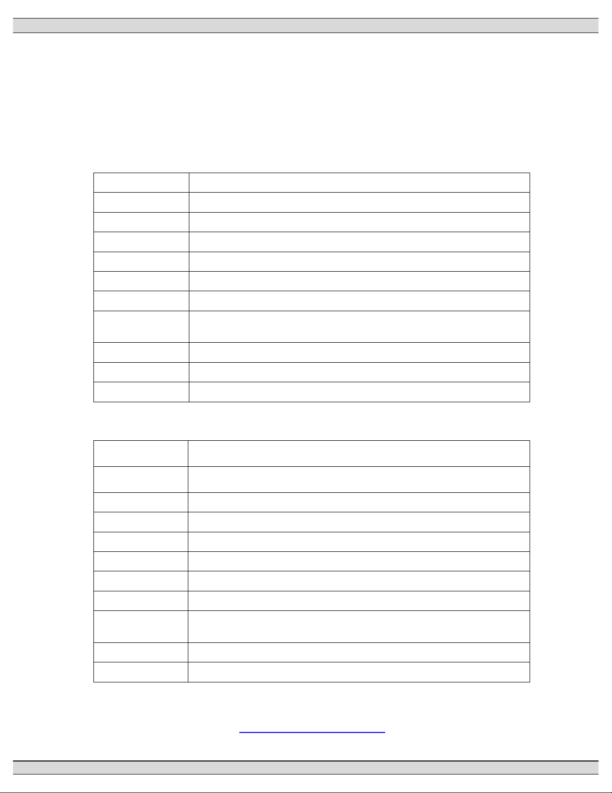
1.1. PRODUCT REVISION HISTORY
The following information provides an historical summary of changes made to this product
since the original release.
Software Version
TSC 800 TRANSFER SWITCH CONTROLLER
2.2 08/08/01
2.1 06/03/27
2.0 04/12/14
1.7 02/04/01
1.6 98/12/15
1.5 N/A
1.4 98/06/15
1.3 98/01/19
Enabled Clock Time Save Feature
Enhanced Phase Balance Features
New Features (Refer to Section 1.2)
Revised Transfer Fail Features and functionality
Added Remote Communication
Unreleased version
Updated Transfer Fail operation
Updated default under/over frequency setpoints, transfer fail
programmability, minor logic revisions
1.2 97/10/10
1.1 97/01/30
1.0 96/06/30
Changed Transfer Switch fail timer to 30 seconds
Upgraded Frequency setting range
Original version
Operating & Service Manual Version
Rev 10 08/09/25
Changes for Version 2.2 TSC 800 Software. Added Information for
ICS ATS Neutral delay time
Rev 9 06/04/24
Minor manual revisions for Version 2.1 TSC 800 Software
Production Release
Rev 8 06/03/27
Enhanced phase balance features
Rev 7 04/12/16
Rev 6 02/04/15
Rev 5 00/07/31
Rev 4 00/03/01
Rev 3 99/02/12
Rev 2 98/12/01
New Features (Refer to Section 1.2)
Changes for Version 1.7 TSC 800 Software
Added Four Position Test Switch Information
General revisions
Added Multi-tap information.
Added Remote Communication features per version 1.6 TSC 800
Software
Rev 1 98/01/21
Rev 0 97/06/04
General Revisions for upgraded TSC 800 software
Original release
Contact Thomson Technology, to obtain applicable instruction manuals. Soft copy of most
current version is available at www.thomsontechnology.com.
PM 049 REV 10 08/09/25 Thomson Technology
1
Page 8

1.2. GENERAL DESCRIPTION
The TSC 800 controller utilizes microprocessor-based design technology, which provides high
accuracy for all voltage sensing and timing functions. The TSC 800 is factory configured to
control all the operational functions and display features of the automatic transfer switch. All
features of the TSC 800 are fully programmable from the front panel LCD display and are
security password protected. The LCD display screen prompts are in plain English, providing
a user-friendly operator interface with many display options available. The microprocessor
design provides many standard features, which were previously only available as add-on
optional features.
2. INSTALLATION
TSC 800 TRANSFER SWITCH CONTROLLER
CAUTION
contents subject to damage by
STATIC ELECTRICITY
This equipment contains static-sensitive parts. Please observe the following anti-static precautions at
all times when handling this equipment. Failure to observe these precautions may cause equipment
failure and/or damage.
• Discharge body static charge before handling the equipment (maintain exposed body contact
with a properly grounded surface while handling the equipment, a grounding wrist strap
can/should also be utilized).
• Do not touch any components on the printed circuit board with your hands or any other
conductive equipment.
Do not place the equipment on or near materials such as Styrofoam, plastic and vinyl. Place the
equipment on properly grounded surfaces and only use an anti-static bag for transporting the
equipment.
2.1. GENERAL INFORMATION
NOTE:
Installations should be done in accordance
with all applicable electrical regulation
codes as required.
PM 049 REV 10 08/09/25 Thomson Technology
2
Page 9

TSC 800 TRANSFER SWITCH CONTROLLER
The following installation guidelines are provided for general information only pertaining to
typical site installations. For specific site installation information, consult Thomson
Technology as required. NOTE: Factory installations of THOMSON TECHNOLOGY supplied
transfer switches that have been tested and proven may deviate from these
recommendations.
2.2. NOTES TO INSTALLER
If the transfer switch has programmable/multi-tap system voltage capability (refer to electrical
schematic), confirm the transfer switch has been configured for the system voltage.
WARNING
Failure to confirm and match transfer
switch voltage with the system voltage
could cause serious equipment damage.
If the transfer switch requires reconfiguring, the TSC 800 controller will also require
reprogramming.
CAUTION!!!
Qualified personnel must complete all installation and/or service work
performed only. Failure to do so may cause personal injury or death.
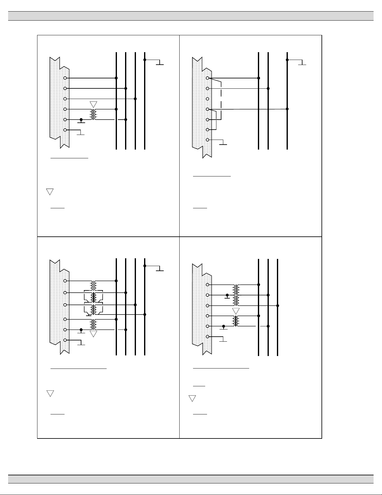
2.3. AC VOLTAGE SENSING INPUT
The TSC 800 can accept direct AC voltage sensing inputs on the generator and utility supplies
from 120-600VAC (nominal). NOTE: Direct input voltage sensing can only be used when the
system utilizes a 3 phase, 4 wire distribution system which has the neutral conductor solidly
grounded. For 3 phase, 3 wire systems (i.e. no neutral) or high voltage systems, potential
transformers must be used (this is also the case where only 1 of the 2 supplies are 3 ph 3 w).
Refer to FIGURES 1-4 for voltage sensing connections.
2.4. AC CONTROL POWER INPUT
The TSC 800 is factory supplied for either 115VAC or 230VAC (nominal) control power input
voltage. Independent AC control power is required from both utility and generator supplies.
AC control power is utilized for internal TSC 800 control circuits and external control device
loads. The TSC 800 requires approximately 12VA AC power for internal control circuits. The
PM 049 REV 10 08/09/25 Thomson Technology
3
Page 10

TSC 800 TRANSFER SWITCH CONTROLLER
maximum external load is limited by output contact ratings (i.e. 10A resistive, 120/250VAC).
Total AC control power requirements for each supply must be determined by adding both
internal and external load requirements.
PM 049 REV 10 08/09/25 Thomson Technology
4
Page 11

TSC 800 TRANSFER SWITCH CONTROLLER
2.5. OUTPUTS
The TSC 800 provides the following types of output circuits:
Engine Start Contact Isolated Form C contact (10A, 250VAC Resistive)
Programmable Output Contact Isolated Form C contact (10A, 250VAC Resistive)
Transfer to Utility Output 250VAC1, 10A (Resistive) powered output contact
Transfer to Generator output 250VAC1, 10A (Resistive) powered output contact
Pre/post-transfer to utility 250VAC1, 3A (Resistive) powered output contact
Pre/post-transfer to generator 250VAC1, 3A (Resistive) powered output contact
Load on utility 250VAC1, 3A (Resistive) powered output contact
Load on generator 250VAC1, 3A (Resistive) powered output contact
1
NOTE: Output voltage is dependent upon AC control power input voltage (i.e. 120VAC or 230VAC
nominal).
Interposing relays are required between the TSC 800 outputs and the end device if loads
exceed the output current rating.
Transient suppression devices are required for all inductive devices sharing wiring or if
physically located near the transfer switch controller.
For AC operated relays or solenoids, use a suitably rated metal oxide varistor (MOV) or
capacitor/resistor suppressor. MOV selection should typically be equal to or slightly greater
than 1.3 times the nominal RMS voltage being applied to the inductive device.
NOTE: Selecting an MOV of too low a value can/will result in a sustained short circuit and
ultimately result in equipment failure.
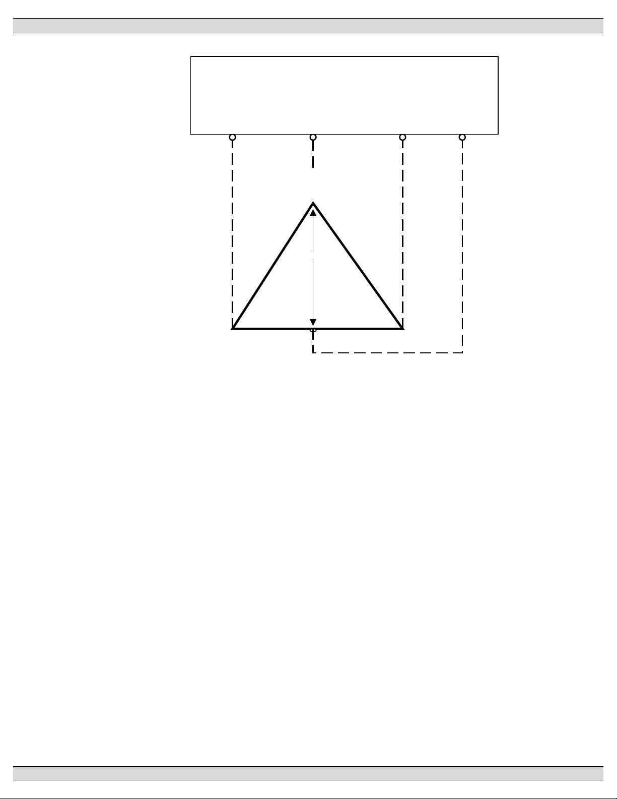
2.6. SYSTEM PHASING-HIGH LEG DELTA SYSTEMS
When the transfer switch is connected to 3 phase 4 wire delta systems and no multi tap
power supply transformers supplied with the ATS, the “High” leg, must be connected to
Phase B of the Utility and/or Generator supply inputs to the ATS (Phase B, colored Orange
per “NEC 384-3(e)” identified as the leg with highest potential with reference to ground). This
will ensure the ATS control power that is internally connected between phase A and neutral is
maintained at 120VAC. Refer to figure below for further details.
WARNING
Failure to match correct system phasing
will result in serious damage to the
TSC 800 controller.
PM 049 REV 10 08/09/25 Thomson Technology
5
Page 12
TSC 800 TRANSFER SWITCH CONTROLLER
Auto matic Tra nsfer
Switch (Utility Supply)
A
(Re d)
PH A
(U A)
PH B
(U B)
B
(O ra ng e)
(High Le g)
240V 240 V
120V 12 0V
208V
N
(W hite )
PH C
(U C )
Neural
(N )
C
(Ye llow)
PM 049 REV 10 08/09/25 Thomson Technology
6
Page 13
TSC 800 TRANSFER SWITCH CONTROLLER
TSC 800
TB1-1
TB1-2
TB1-3
TB3-1
TB3-5
TB2-18
1
120
GRD
GRD
BA C N
VOLTAGE INPUTS
600VAC L-L, 347VAC L-N
480VAC L-L, 277VAC L-N
380VAC L-L, 220VAC L-N
208VAC L-L, 120VAC L-N
PT REQUIRED FOR TRANSFER SWITCH M ECHANISM POWER
1
(MUST BE SIZED TO SUIT POWER REQUIREMENTS).
FIG:1
3Ø, 4W 208/380/480/600VAC DIRECT SENSING
NOTE:
UTILITY VOLTAGE SENSING AND
CONTROL POWER SHOWN ONLY.
GRD
TSC 800
TB1-1
TB1-2
TB1-3
TB1-10
TB3-1
TB3-5
TB2-18
NO CONNECTION
GRD
L2L1 N
VOLTAGE INPUTS
240VAC L-L, 120VAC L-N
FIG:2
1Ø, 3W 120/240VAC DIRECT SENSING
NOTE:
UTILITY VOLTAGE SENSING SHOWN ONLY.
GRD
TSC 800
TB1-1
TB1-2
TB1-3
TB3-1
TB3-5
TB2-18
120
120
120
120
GRD
GRD
GRD
1
BA C N
SECONDARY PT VOLTAGE
208VAC L-L, 120VAC L-N
120VAC L-L, 69VAC L-N
PT REQUIRED FOR TRANSFER SWITCH M ECHANISM POWER
1
(MUST BE SIZED TO SUIT POWER REQUIREMENTS).
FIG:3
3Ø, 4W WYE PT's
NOTE:
UTILITY VOLTAGE SENSING SHOWN ONLY.
GRD
TSC 800
TB1-1
TB1-2
TB1-3
TB3-1
TB3-5
TB2-18
120
120
GRD
1
120
GRD
GRD
BA C
SECONDARY PT VOLTAGE
120VAC L-L [NO NEUTRAL]
NOTE
: ØB IS GROUNDED
PT REQUIRED FOR TRANSFER SWITCH M ECHANISM POWER
1
(MUST BE SIZED TO SUIT POWER REQUIREMENTS).
FIG:4
3Ø, 3W DELTA PT's
NOTE:
UTILITY VOLTAGE SENSING SHOWN ONLY.
REVISED
G:\ENGINEER\PRODUCTS\TSC800\852619.VSD
PM 049 REV 10 08/09/25 Thomson Technology
7
97/06/27 09:12 AM
Page 14

TSC 800 TRANSFER SWITCH CONTROLLER
2.7. EXTERNAL PANEL CONTROL WIRING
As a minimum, all control wiring shall conform to the local regulatory authority on electrical
installations. Specific wire sizes listed below are for typical circuits of distances up to 500ft
(150m)1, are as follows:
Utility or Generator Voltage Sensing #14 AWG (2.5mm2)
Transfer output signals #14 AWG (2.5mm2)
Remote Start Contact for Engine Controls #14 AWG (2.5mm2)
NOTE: For long control wire runs or noisy electrical environments the control wires
should be twisted & shielded with a suitable drain wire. The shielded cable drain wire
must be grounded at one end only. The drain wire grounding location may vary as
micro-processor controllers generally exist at both ends (engine generator set &
transfer switch) and one may be more susceptible depending on the level of induced
noise. The most susceptible controller will requiring the shield ground point as close
as possible to the controller. Wire runs from 500ft to 1000ft should be twisted and
shielded and increased to #12 AWG where total loop resistance is greater than 5
ohms.
1
For distances exceeding 1000ft. (300m) consult Thomson Technology
2.8. REMOTE START CONTACT FIELD WIRING
Field wiring of a remote start contact from a transfer switch to a control panel should conform
to the following guidelines to avoid possible controller malfunction and/or damage.
2.8.1. Remote start contact wires (2 #14 AWG (2.5mm2)) should be run in a separate
conduit (ferromagnetic type) and in all cases separated from any AC wiring.
2.8.2. Avoid wiring near AC power cables to prevent pick-up of induced voltages.
2.8.3. An interposing relay may be required if field-wiring distance is excessively long
(i.e. greater than 1000 feet (300m)) and/or if a remote contact has a resistance
of greater than 5.0 ohms. In extremely noisy environments, the wire run
lengths indicated may not provide reliable operation and can only be corrected
by the use of an interposing relay. The interposing relay is generally installed
at the engine controls and utilizes DC power. It is strongly suggested that the
ground return wire of the interposing relay be used for the interface to the TSC
800 remote start contact, this will ensure integrity of the DC power supply to the
engine generator set controls in the event of a shorted or grounded wire remote
start interface wire.
PM 049 REV 10 08/09/25 Thomson Technology
8
Page 15

TSC 800 TRANSFER SWITCH CONTROLLER
2.8.4. The remote start contact provided is voltage free (i.e. dry contact). Exposing
the remote start contact to voltage or current levels in excess of its rating will
damage the transfer controller.
2.9. COMMMUNICATION CABLE
Communication cable wiring from the controller’s communication port must be suitably routed
to protect it from sources of electrical interference. Guidelines for protection against possible
electrical interference are as follows:
• Use high quality, 8 conductor shielded cable only with drain wire grounded at the
controller end only.
• Route the communication cable at least 3 M (10’) away from sources of electrical
noise such as variable speed motor drives, high voltage power conductors, UPS
systems, transformers, rectifiers etc.
• Use separate, dedicated conduit runs for all communication cables. Do not tightly
bundle communication cables together in the conduit. Conduit should be
ferromagnetic type near sources of possible electrical interference. The entire
length of conduit should be grounded to building earth ground.
• When communication cables must cross over low or high voltage AC power
conductors, the communication cables must cross at right angles and not in
parallel with the conductors.
For additional information on protection against electrical interference, contact
THOMSON TECHNOLOGY factory.
PM 049 REV 10 08/09/25 Thomson Technology
9
Page 16
TSC 800 TRANSFER SWITCH CONTROLLER
2.10. DIELECTRIC TESTING
Do not perform any high voltage dielectric testing on the transfer switch with the TSC 800
controller connected into the circuit, as serious damage will occur to the controller. All AC
control fuses or control circuit isolation plugs connected to the TSC 800 must be
removed/disconnected if high voltage dielectric testing is performed on the transfer switch.
3. DESCRIPTION
The TSC 800 controller consists of two parts; a Lexan faceplate, which is mounted externally on the
transfer switch door, and a printed circuit board (PCB), which is mounted inside the transfer switch
door.
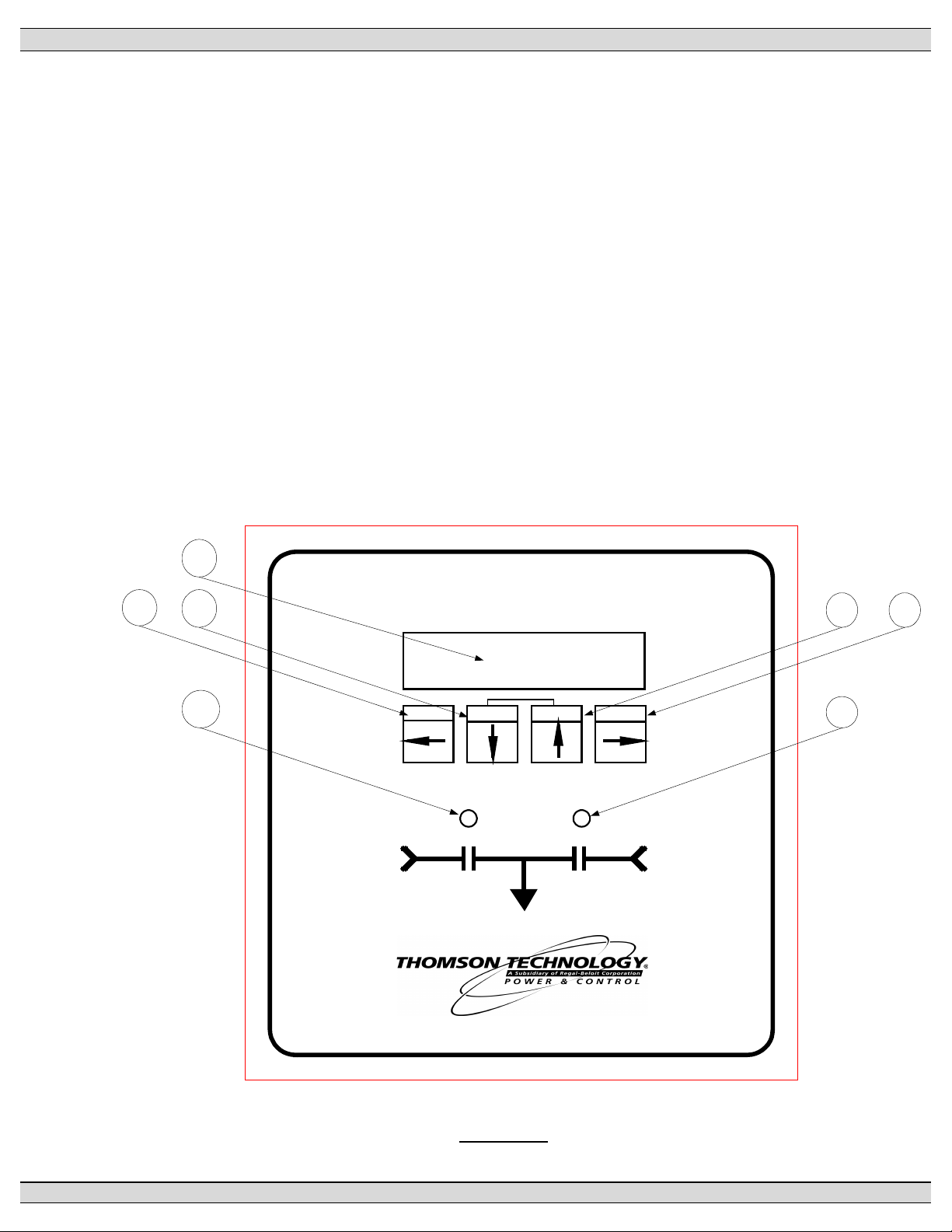
3.1. LEXAN FACEPLATE
The Lexan faceplate is shown as in FIGURE 7. The Lexan pushbuttons are connected to the
main PCB via plug-in ribbon cable. The main features of the Lexan faceplate are described
as follows with reference to FIGURE 7.
1
AUTOMATIC TRANSFER CONTROLLER
2
3
6
UTILITY
SUPPLY
MODEL TSC 800
LAMP TEST
EXIT DECREMENT INCREMENT ENTER
LOAD
54
7
GENERATOR
SUPPLY
FULL FILENAME
DRAWING1
DATE
02/04/04 11:58AM
FIGURE# 7
PM 049 REV 10 08/09/25 Thomson Technology
10
Page 17

TSC 800 TRANSFER SWITCH CONTROLLER
LCD viewing window. The LCD display is mounted on the main PCB which is visible
from the lexan faceplate.
EXIT pushbutton. The EXIT function is used to scroll backwards through the status
menus or programming prompts to the previous item. The EXIT function is used to
“exit” the programming menu by holding this button down for approximately 2 seconds
while in the programming mode.
DECREMENT pushbutton. The DECREMENT function is used to change a
programming value while in the programming mode. When this pushbutton is held
down, the displayed value will be “decremented” to a lower value as desired. NOTE:
The longer the pushbutton is held down, the faster the value will be decremented.
INCREMENT pushbutton. The INCREMENT function is used to change a
programming value while in the programming mode. When this pushbutton is held
down, the displayed value will be “incremented” to a higher value as desired. NOTE:
The longer the pushbutton is held down, the faster the value will be incremented.
ENTER pushbutton. The ENTER function is used to scroll forwards through the status
menus or programming prompts to the next item. The ENTER function is used to
“enter” and accept new programming or operating mode changes after a new value
has been selected (NOTE: Pressing the Exit button instead of the Enter button will
reject the newly selected value and retain the original value). NOTE: In the
programming mode, the longer the ENTER pushbutton is held down, the faster the
next menu prompt will appear.
Load on Utility supply LED light viewing window
Load on Generator supply LED light viewing window
NOTE: A lamp test feature is provided to test all LED lights as well as the LCD display.
To activate the lamp test feature, simultaneously push the INCREMENT and
DECREMENT pushbuttons. All LEDs and LCD display pixels should illuminate for
approximately 2 seconds then return to their original status. The Lamp Test feature is
also used to clear active fault conditions and return the controller to normal operation.
NOTE: An active Timer Bypass feature is provided to allow a manual initiated bypass.
To activate the feature, simultaneously push the DECREMENT and ENTER
pushbuttons. The previously bypassed timer will operate normally during its next
cycle. Refer to Timer Bypass section for related timers.
PM 049 REV 10 08/09/25 Thomson Technology
11
Page 18
TSC 800 TRANSFER SWITCH CONTROLLER
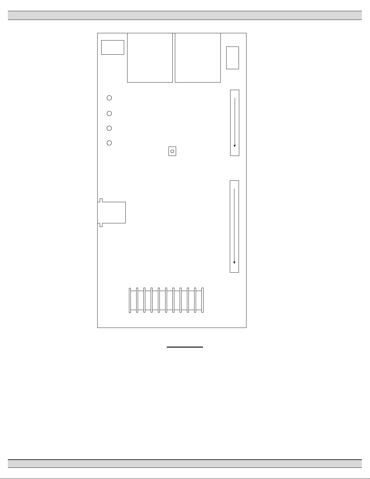
4 3 2 1
HD2
WATCHDOG
ENGINE START
TRANSFER
TO UTILITY
TRANSFER
TO GENERATOR
UTILIT Y SUPPLY
TRANSFORMER
CONTRAST
GENERATOR SUPPLY
TRANSFORMER
HD1
TB3
TB2
1
2
3
4
1
12
1
1
J7
COMM
RJ45
Connector
TB1
5
4
3
2
1
G;\ENGINEER\PRODUCTS\TSC800\852613b.VSD
FIGURE # 8
3.2. PRINTED CIRCUIT BOARD
18
9
8
7
6
10
The printed circuit board (PCB) is shown in FIGURE 8. The PCB contains the following user
interface items:
3.2.1. POWER SUPPLY INPUT VOLTAGE SELECTION
The controller power supply input voltage level selection is made via two connector
plugs, which are located on the PCB and are identified as HD1 and HD2. Voltage
selection plug assemblies are unique for each power supply input level voltage
PM 049 REV 10 08/09/25 Thomson Technology
12
Page 19
TSC 800 TRANSFER SWITCH CONTROLLER
arrangement and must match the intended voltage level. Controller failure may result
if incorrectly configured.
The TSC 800 is factory configured for a specific power supply voltage input as
designated by voltage header plugs labeled as follows:
115V - designates a 115V power supply input voltage
230V - designates a 230V power supply input voltage
3.2.2. TERMINAL BLOCKS
Three terminal blocks are located on the PCB as follows:
TB1 High voltage sensing terminal block (120-600VAC)
WARNING
Voltage sensing circuits are capable of lethal voltages while
energized. Standard safety procedures should be followed and
be performed by qualified personnel only. Failure to do so may
cause personnel injury and/or death.
TB2 Transfer control terminal block for output contacts and low voltage inputs
TB3 Transfer control terminal block for 115/230v input and output circuits
3.2.3. DIAGNOSTIC LEDs
The TSC 800 controller provides four diagnostic LED lights that are mounted on the
rear of the printed circuit board as per FIGURE 8. Their functions are described as
follows:
WATCHDOG This LED flashes on and off at irregular intervals that
indicate that the microprocessor is functioning
normally.
ENGINE START This LED is illuminated whenever the TSC 800 is
initiating an Engine Start (except when there is no
power to the TSC 800 controller).
TRANSFER TO UTILITY This LED is illuminated whenever the TSC 800 is
initiating a Transfer to Utility signal.
TRANSFER TO GEN This LED is illuminated whenever the TSC 800 is
initiating a Transfer to Generator signal.
NOTE: All LEDs will be illuminated whenever a lamp test function is performed.
PM 049 REV 10 08/09/25 Thomson Technology
13
Page 20

TSC 800 TRANSFER SWITCH CONTROLLER
3.2.4. COMMUNICATION PORT
A communication port is provided to interconnect to a remote communication system
for remote monitoring and control of the transfer switch. Refer to Section 4 for
additional information.
3.2.5. CONTRAST ADJUSTMENT
A contrast adjustment potentiometer is located on the PCB and is factory set for
ambient temperatures of 15° to 30° Celsius. For different ambient temperatures,
consult the factory for adjustment procedures.
4. REMOTE COMMUNICATION
The TSC 800 transfer switch controller is available with a remote communication feature. The remote
communication feature allows a TSC 800 controller to be monitored and controlled from a remote
location via serial communication link to a personal computer (PC). PC’s may be connected locally
via serial communication cable to the TSC 800 or remotely via modem and telephone systems.
Remote communication can be via customer-supplied equipment or with an external communication
interface module (CIM) as manufactured by Thomson Technology.
NOTE:
The CIM module may be located in the engine control panel
provided the maximum distance between the CIM and TSC 800
controller is not exceeded as per the following information.
Refer to the installation section of this manual for further
information.
The CIM module utilizes an internal modem and contains ModbusTM protocol to interface with different
remote monitoring software programs. Refer to separate literature for detailed information on the
CIM module.
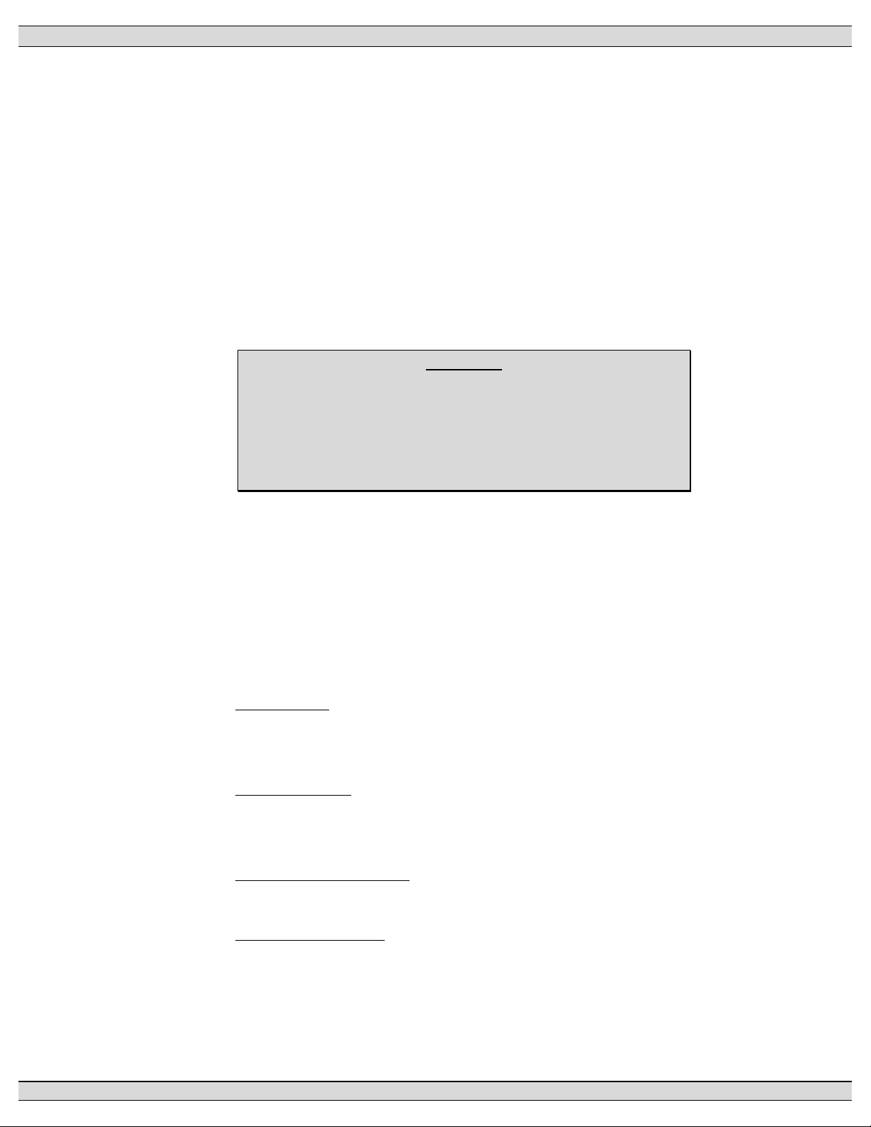
The TSC 800 communication port utilizes a RS422 data transmission signal that is directly
interconnected to the CIM module via an 8 conductor, shielded cable with plug-in RJ45 connectors.
Refer to FIGURES 9 & 10 for detailed information on direct connected or remote connected PC
applications with CIM module.
TM
Trademarks belong to their respective parties.
NOTE: Both phone and serial communications ports cannot be connected at the same time. Doing
so will result in no communication and/or possible CIM failure.
PM 049 REV 10 08/09/25 Thomson Technology
14
Page 21
TSC 800 TRANSFER SWITCH CONTROLLER
CIM
Communication
Interface Module
+-
Phone
no connection
Port 2A
G
GRD
Port 3B
GRD
TSC 800
Transfer
Controller
RS 232 Signal
15M (50ft)**
maximum
cable length
null modem
connector
Personal
Computer
DC Power
8-35Vdc
**Communication cable wiring must be suitably routed to
protect it from sources of electrical interference. Refer to
installation section for further information.
8 conductor
Shielded Cable c/w
RJ45 connectors
305M
(1000ft)**
maximum
cable length
G:\ENGINEER\PRODUCTS\TSC800\852621.VSD
FIGURE #9 TSC 800 WITH CIM MODULE & DIRECT CONNECTED PC (RS232)
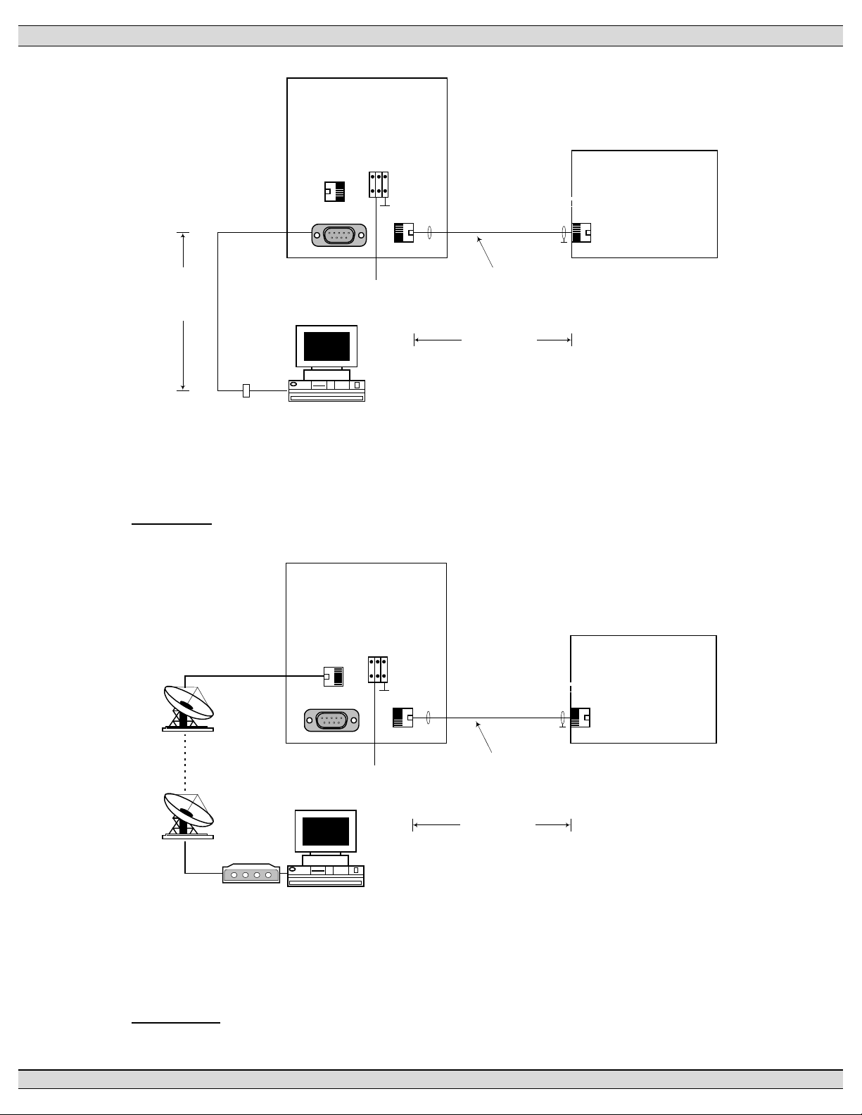
CIM
Communication
Interface Module
+-
Phone
Port 2A
no connection
G
GRD
Port 3B
DC Power
8-35Vdc
TSC 800
Transfer
Controller
GRD
8 conductor
Shielded Cable c/w
RJ45 connectors
305M (1000ft)**
maximum
cable length
**Communication cable wiring must be suitably routed to
Modem
Personal
Computer
protect it from sources of electrical interference. Refer to
installation section for further information.
G:\ENGINEER\PRODUCTS\TSC800\852622.VSD
FIGURE #10 TSC 800 WITH CIM MODULE & REMOTE CONNECTED PC
PM 049 REV 10 08/09/25 Thomson Technology
15
Page 22
TSC 800 TRANSFER SWITCH CONTROLLER
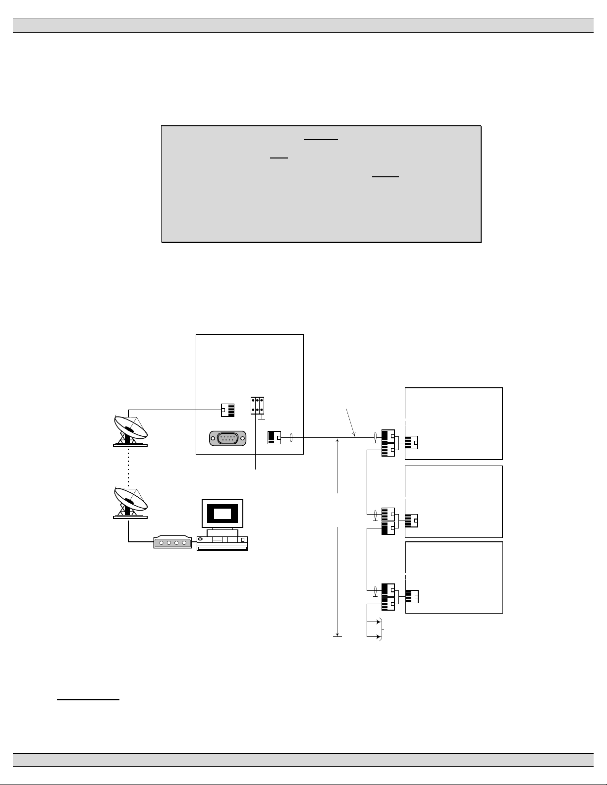
The TSC 800 RS422 communication port allows multiple TSC 800 controllers to be directly
interconnected together to form a single network system. Up to 10 TSC 800 controllers may be
interconnected to a single CIM module.
NOTE:
TSC 800 controllers and MEC 20 engine-generator controllers
may be interconnected together via the same communication
network provided the maximum number of controllers and
interconnection distances are not exceeded. For additional
information, refer to associated product instruction manuals.
Each TSC 800 controller is programmed with a unique communication node address number for the
remote communication system to reference. The network system may be connected to a local PC or
to a remote PC via telephone system and CIM module. Refer to FIGURE #11 for a typical TSC 800
network system with CIM module.
Communication
Interface Module
Phone
Port 2A
no connection
THS
Modem
**Communication cable wiring must be
suitably routed to protect it from sources of
electrical interference. Refer to installation
section for further information.
Personal
Computer
CIM
+-
G
GRD
Port 3B
DC Power
8-35Vdc
8 conductor
Shielded Cable c/w
RJ45 connectors
GRD
305M
(1000ft)**
maximum
cable length
GRD
GRD
TSC 800
Transfer
Controller
#1
TSC 800
Transfer
Controller
#2
TSC 800
Transfer
Controller
#3
To additional TSC 800 controllers
(maximum 10 total per network)
G:\ENGINEER\PRODUCTS\TSC800\852623.VSD
FIGURE #11 NETWORKED TSC 800 INTERCONNECTION DIAGRAM
PM 049 REV 10 08/09/25 Thomson Technology
16
Page 23
TSC 800 TRANSFER SWITCH CONTROLLER
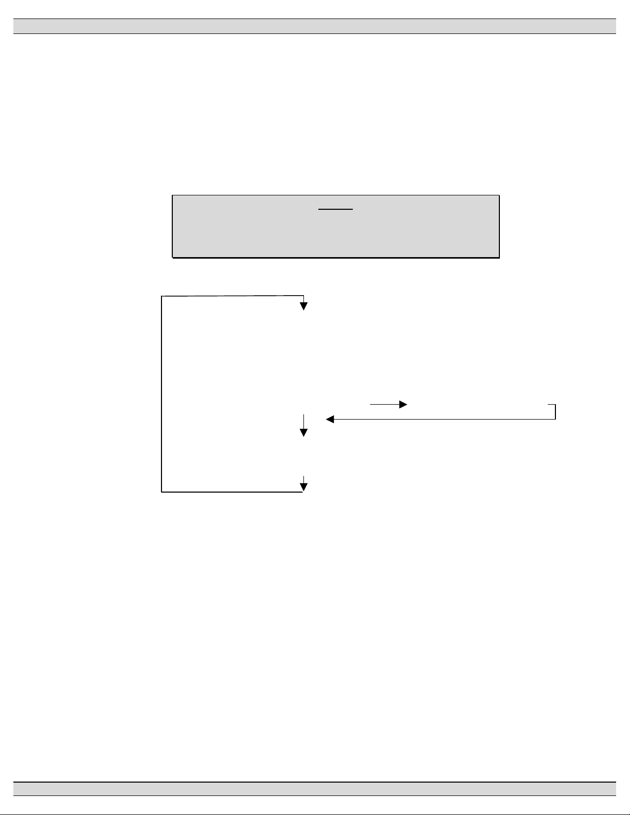
5. TSC 800 DISPLAY MENUS
The TSC 800 contains a Liquid Crystal Display (LCD) that is visible on the front faceplate. The LCD
has pre-programmed display menus which are automatically displayed in an auto-Scrolling mode or
they may be selected manually by pressing the ENTER or EXIT pushbuttons in succession until the
desired menu is displayed. The display menu types and order in which they are programmed are as
follows:
NOTE:
The following display menus are provided in TSC 800 Software
version 2.0 (or higher).
SYSTEM TIME
STATS MENU
ATS MODE MENU
PROGRAM MENU
SYSTEM STATUS TIMER COUNTDOWN
UTILITY SUPPLY MENU
GEN SUPPLY MENU
NOTE: ATS MODE MENU access may be inhibited. Refer to programming instruction
for further details.
PM 049 REV 10 08/09/25 Thomson Technology
17
Page 24
TSC 800 TRANSFER SWITCH CONTROLLER
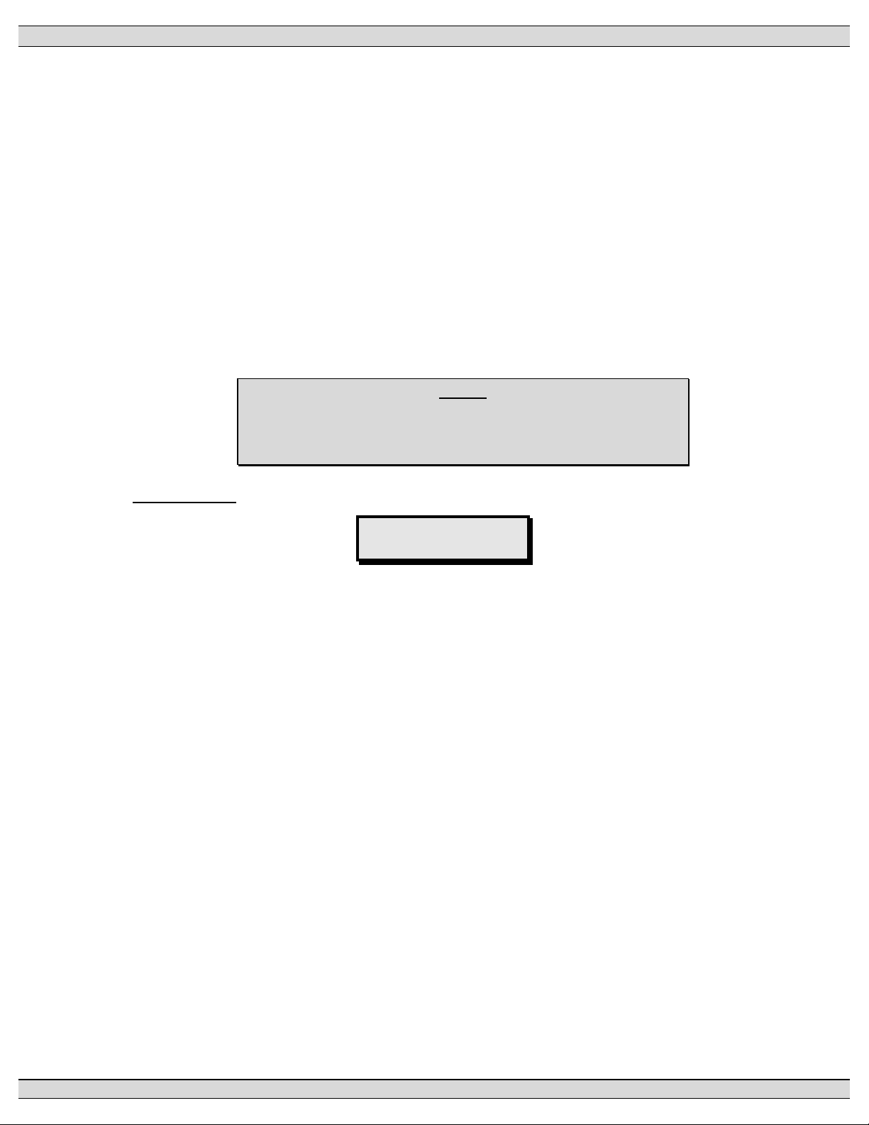
5.1. SYSTEM TIME MENU
The system time menu is used to show current system time and week number. The TSC 800
controller uses its internal time clock to reference when an automatic exercising operation (if
pre-programmed) is to occur. To change the system time, refer to the “time clock adjustment”
section of this manual. Should control power be lost to the TSC 800 controller for longer than
1-5 minutes, the time clock setting will be saved at the last time value. When the controller is
re-energized, the time setting will indicate the approximate time when the controller lost power
and then will resume keeping system Time. To re-adjust the system time clock, refer to
section 6.3.
NOTE:
The following system Time menu is provided in TSC 800
Software version 2.0 (or higher).
LCD DISPLAY
System Time
Mon
Displays the day of the week (e.g. Monday)
Displays the week number (e.g. 1-4)
Displays the current time in hours (24-hour clock): hour: min: seconds
1
12:24:31
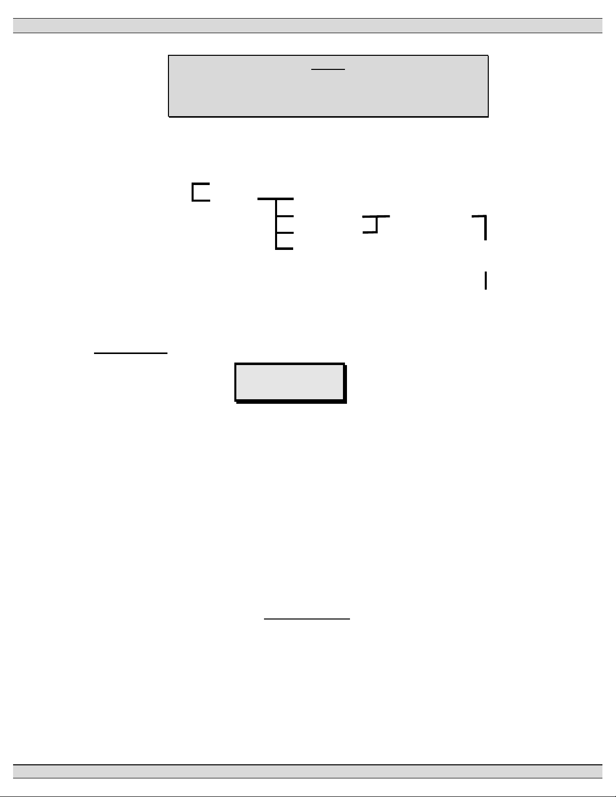
5.2. ATS MODE MENU
The ATS Mode Menu provides manually selectable operating modes which includes
On/Offload testing features (comparable features also available via external inputs utilizing an
optional FTS4 selector switch). The Internal and External ATS Mode inputs operate in a
parallel fashion; the Mode of Operation will be determined by the highest priority selected by
either format. The priority levels are as follows (highest to lowest priority):
1) Off (Controller out of Service, no control logic applied)
2) Onload Test
3) Offload Test
4) Auto
A utility power failure will over ride all but “Off”. In the event of a generator failure and the
utility supply is available and considered normal, the ATS will return to the utility supply except
when “Off” selected.
PM 049 REV 10 08/09/25 Thomson Technology
18
Page 25
TSC 800 TRANSFER SWITCH CONTROLLER
NOTE:
The following test menu is provided in TSC 800 Software
version 2.0 (or higher).
The ATS Mode sub-menus are organized as follows:
ATS Mode Menu No
Yes Auto (Automatic Operation & Programmed Test Mode)
Offload Test Continuous Test
Onload Test
Off (Controller Disabled) Timed Test: Selectable
15 - 240 Min.
Automatic Return to “Auto Mode”
LCD DISPLAY
ATS Mode Menu
No
Displays two messages that may be toggled between YES or NO by pressing the
INCREMENT or DECREMENT pushbuttons. Their functions are described as follows:
No Status message only, a change is required to gain access.
Yes The required variable to be entered to gain access and proceed. If the
password protect feature is enabled a prompt will appear requiring a
level 2 or greater security code be entered to allow a read-write access.
Entering a level 1 password will only permit a read only access.
The following ATS Mode Menu options are provided:
Auto This is the Default Selection and is required to enable all automatic
features of the controller. In this mode the TSC 800 Controller will
automatically transfer the load to the appropriate source based on
availability (the Utility supply is considered the preferred source). The
TSC 800 will provide automatic timed testing if enabled in programming.
Manual testing is disabled when the Auto ATS mode is selected (NOTE:
PM 049 REV 10 08/09/25 Thomson Technology
19
Page 26

TSC 800 TRANSFER SWITCH CONTROLLER
the external mode inputs input will over ride ATS Mode Menu selected
Auto mode).
Offload Test When the Offload Test prompt is selected and entered, the generator
will immediately start and operate offload and will not permit a load
transfer. The test menu will display Continuous Test, to select a timed
test use the INCREMENT or DECREMENT pushbutton to scroll and
select a test duration time, press enter to accept the time (selectable in
15 minutes increments from 15 – 240 min.). The generator will remain
running until a different mode is selected and entered or the timed test
duration expires (selecting Auto will immediately terminate the test). On
expiry of the timed test the operating mode automatically reverts to
Auto.
NOTE: If the Utility supply fails during this test mode, the load will
automatically transfer to the generator if within acceptable limits.
Onload Test When the Onload Test prompt is selected and entered, the generator
will immediately start and transfer on load. The test menu will display
Continuous Test, to select a timed test use the INCREMENT or
DECREMENT pushbutton to scroll and select a test duration time, press
enter to accept the time (selectable in 15 minutes increments from 15 –
240 min.). The generator will remain running until a different mode is
selected and entered or the timed test duration expires (selecting Auto
will terminate the test after the Utility Return Timer has expired). On
expiry of the timed test the operating mode automatically reverts to
Auto.
NOTE: Should the Generator fail during the onload test and the Utility
supply is available and within acceptable limits the load will be
transferred on expiry of the generator under voltage delays.
Off The TSC 800 Controller is considered out of Service. The transfer
mechanism logic outputs are dropped out and disabled. The transfer
switch will remain in its last position and the remote start removed if
previously enabled. Manual and auto test features are disabled. This
selection takes precedence over all other modes.
PM 049 REV 10 08/09/25 Thomson Technology
20
Page 27

TSC 800 TRANSFER SWITCH CONTROLLER
NOTE: When this mode is selected the local generator controls should
also be placed in OFF. Failing to do can result in cyclical engine
starting. On loss of Utility supply in this state (loss of control power to
the TSC 800) the engine start contact will drop out after approximately 4
minutes resulting in generator starting and stopping (the cycle will
repeat approximately every 4 minutes after the control power is
removed).
NOTE: On return to normal service the Engine Start output is inhibited
(held up) for approximately 8 – 10 seconds. Requesting another mode
of operation during this time, which requires the engine start contact to
close, will be ignored.
PM 049 REV 10 08/09/25 Thomson Technology
21
Page 28

TSC 800 TRANSFER SWITCH CONTROLLER
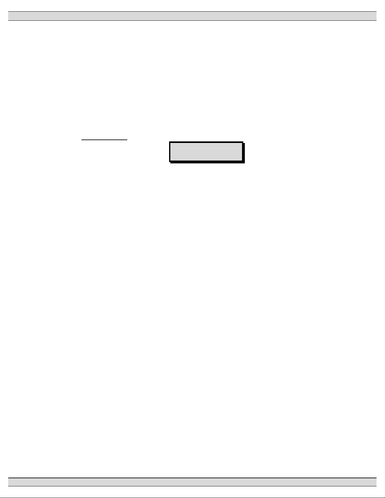
5.3. TSC 800 PROGRAM MENU
The programming menu is used to access the TSC 800’s programmable functions such as
time delays, voltage/frequency setpoints, calibration and time clock adjustments.
Access to the programming sub-menus can only be obtained with a security password
number. The sub menus are organized as follows:
Programming Menu No
Yes Password
LCD DISPLAY
Program Menu
No
Displays two messages that may be toggled between YES or NO by pressing the
INCREMENT or DECREMENT pushbuttons. Their functions are described as follows:
NO Status message only, a change is required to gain access.
YES The required variable to be entered to gain access and proceed. The password
protection prompt will appear requiring a level 2 or greater security code be
entered to provide a read-write access. Entering a level 1 password will permit
a read only access.
5.4. SYSTEM OPERATION MENU
The system operation menu provides the operator with information as to current status of both
the utility and generator supplies.
NOTE:
The system operation menu screen may be momentarily
replaced with a time delay countdown screen when a
transfer sequence is initiated. The display will
automatically return to the previous menu following expiry
of the timing sequence.
PM 049 REV 10 08/09/25 Thomson Technology
22
Page 29

TSC 800 TRANSFER SWITCH CONTROLLER
The system operation sub-menus are organized as follows:
Utility Normal
Failed
Return Delay
Gen ATS In OFF
In Auto
Starting
Failed
Running
Normal
Cooling
Auto Offload Test
Manual Offload Test
Auto Onload Test
Manual Onload Test
Commit To Transfer
LCD DISPLAY
Util Normal
Gen Onload Test
Displays utility supply status conditions. There are three status conditions:
Normal Load is on the utility supply and the utility’s voltage and
frequency is normal.
Failed Utility supply voltage and/or frequency are outside the
nominal programmed limits (e.g. failed condition).
Return Delay Load is on the generator supply and the utility supply is
ready to transfer. This is a temporary condition due to either
a test mode being selected or during a utility return time
delay.
Displays generator supply status conditions. There are twelve status conditions as
follows:
ATS In Off The ATS Mode has been set to OFF via the Internal or
External switch input. The Controller will display the
message “Controller Out of Service”.
In Auto The ATS Mode via the Internal ATS Mode Menu has been
set to Auto.
PM 049 REV 10 08/09/25 Thomson Technology
23
Page 30

TSC 800 TRANSFER SWITCH CONTROLLER
Starting Engine start signal has been initiated, and the TSC 800
sensors are waiting for generator voltage to build up.
Failed Generator is signaled to operate; however its voltage
and/or frequency is outside the nominal programmed limits
(e.g. failed condition).
Running The generator is running (within programmed limits) but
not requested to transfer on load by the controller.
Normal The generator is running due to a failed utility supply.
Cooling The generator is running (within programmed limits) during
the programmed cooldown delay.
Auto Offload Test The generator is running off load due to a
programmed exercise timer mode.
Manual Offload Test The generator is running off load due to manually
initiated off load test mode via the front-panel
pushbuttons or external inputs.
Auto Onload Test The generator is running on load due to a
programmed exercise timer mode.
Manual Onload Test The generator is running on load due to manually
initiated on load test mode via the front-panel
pushbuttons or external inputs.
Commit To Transfer When enabled, the generator will be committed to
transferring onload if the loss of utility is detected
and the engine start issued. The generator will
remain onload for the duration of the power failure
and the transfer return time. If the generator fails
to start within 5 minutes the commit to transfer
request is cancelled.
5.5. TIMER COUNTDOWN MENUS
Timer countdown menus are automatically displayed when a specific time delay function
occurs during a transfer sequence. When a time delay begins, the LCD display will indicate
the time delay function name (e.g. Gen Start Delay) and the current time remaining in the
countdown sequence. When the timing function is complete, the LCD display will
automatically change to either the next timing sequence countdown display or return to auto
scrolling the system status screens.
PM 049 REV 10 08/09/25 Thomson Technology
24
Page 31

TSC 800 TRANSFER SWITCH CONTROLLER
LCD DISPLAY
Gen Start
Delay
Displays specific time delay function currently in operation
Displays current time in seconds that are left in the specific timing sequence.
45 Sec
NOTE:
During a timer countdown sequence, scrolling to
a different display screen is possible by pressing
either the ENTER or EXIT pushbuttons.
The following timer countdown screens are provided and displayed in seconds of time
remaining:
Gen Start Delay Gen Warm up Delay
Gen Cooling Delay Utility Return Delay
PreTransfer Delay PostTransfer Delay
Finding Neutral Neutral Delay
PSD Max Open Time Transferring
Syncing (Close Transition Feature Only)
5.6. UTILITY SUPPLY MENU
The utility supply menu allows the operator to view the utility supply voltage and frequency
values.
LCD DISPLAY
600
Util 60.0Hz
600
600
Displays utility supply frequency in hertz (Hz). The frequency is displayed with a
resolution of 1/10 of a hertz.
Displays utility supply voltage as follows:
• 3-phase system: LINE TO LINE VOLTAGE--Phases A to B
• 1-phase system: LINE TO LINE VOLTAGE--Phases L1 to L2
Displays utility supply voltage as follows:
• 3-phase system: LINE TO LINE VOLTAGE--Phases B to C
• 1-phase system: LINE TO NEUTRAL VOLTAGE--Phases L1 to N
PM 049 REV 10 08/09/25 Thomson Technology
25
Page 32
TSC 800 TRANSFER SWITCH CONTROLLER
Displays utility supply voltage as follows:
• 3-phase system: LINE TO LINE VOLTAGE--Phases C to A
• 1-phase system: LINE TO NEUTRAL VOLTAGE--Phases L2 to N
5.7. GENERATOR SUPPLY MENU
The generator supply menu allows the operator to view the generator supply voltage and
frequency values.
LCD DISPLAY
600
Gen 60.0Hz
600
600
Displays generator supply frequency in hertz (Hz). The frequency is displayed with a
resolution of 1/10 of a hertz.
Displays generator supply voltage as follows:
• 3-phase system: LINE TO LINE VOLTAGE--Phases A to B
• 1-phase system: LINE TO LINE VOLTAGE--Phases L1 to L2
Displays generator supply voltage as follows:
• 3-phase system: LINE TO LINE VOLTAGE--Phases B to C
• 1-phase system: LINE TO NEUTRAL VOLTAGE--Phases L1 to N
Displays generator supply voltage as follows:
• 3-phase system: LINE TO LINE VOLTAGE--Phases C to A
• 1-phase system: LINE TO NEUTRAL VOLTAGE--Phases L2 to N
NOTE: The load bus voltages are viewable only in the Programming Menu. When
selected as 3-phase load sensing it will be displayed as listed above for 3-phase
systems. When selected as 1-phase, only the L1 to L2 voltage will be displayed as a
line-to-line value. 3-phase load sensing can only be selected if all 3 phases of the load
bus are wired to the TSC 800 controller. Most transfer switches manufactured prior to
December 2004 will not have the C phase load bus wiring installed and must be set for
1-phase load sensing.
PM 049 REV 10 08/09/25 Thomson Technology
26
Page 33

TSC 800 TRANSFER SWITCH CONTROLLER
5.8. STATS MENU
The STATS menu displays the recorded data logging for the following events:
NOTE:
The following stats menu is provided in TSC 800 Software
version 2.0 (or higher).
o Total Number of Transfers
o Total Number of Transfers due to source failure
o Number of Hours Controller is energized
o Number of Hours Load is on Utility
o Number of Hours Load is on Generator
The TSC 800 data logging has the maximum number of events memory as follows:
o The limit for the Total Transfers and SRC Fail Transfers is 10,000.
o The limit for the Total Hours, Load On SRC1 Hours, and Load On SRC2 Hours
is 160,000 hours.
LCD DISPLAY
Total Transfers
20
Displays the recorded data
NOTE: Zeroing of the Statistic Records can be accessed by entering the Program Menu with
a master password number. Consult THOMSON TECHNOLOGY factory for master password
number if required.
PM 049 REV 10 08/09/25 Thomson Technology
27
Page 34
TSC 800 TRANSFER SWITCH CONTROLLER
6. OPERATING INSTRUCTIONS
To operate the TSC 800 controller and associated transfer switch using the front faceplate
pushbuttons, refer to the following detailed operating instruction sub-section descriptions.
6.1. AUTOMATIC SEQUENCE OF OPERATION
6.1.1. NORMAL SEQUENCE OF OPERATION (OPEN TRANSITION
TRANSFER)
Under normal operating conditions, the transfer switch operates automatically during a
failure and restoration of utility power and does not require operator intervention.
NOTE:
Refer to sections 6.5 & 6.10 which may require operator
intervention
When utility supply voltage drops below a preset nominal value (70 – 99% of rated
adjustable) on any phase, an engine start delay circuit will be initiated. Following
expiry of the engine start delay period (0 - 60 sec. adjustable) an engine start signal
(contact closure) will be given.
Once the engine starts, the transfer switch controller will monitor the generators
voltage and frequency levels. Once the generator voltage and frequency rises above
preset values (70 – 99% nominal adjustable) a warm up time delay will be initiated.
Once the warm up timer (0 - 3000 Sec adjustable) expires the transfer to utility supply
signal will be removed (i.e. contact opening) and the transfer to generator supply
signal (contact closure) will be given to the transfer switch mechanism. The load will
then transfer from the utility supply (i.e. opening the utility power switching device) to
the generator supply (closing the generator power switching device) to complete a
break-before-make open transition transfer sequence.
The generator will continue to supply the load until the utility supply has returned and
the retransfer sequence is completed as follows: When the utility supply voltage is
restored to above the present values (70 - 99% of rated adjustable) on all phases, a
utility return delay circuit will be initiated. Following expiry of the utility return timer (0 –
50.0 min. adjustable), the transfer to generator supply signal will be removed (contact
PM 049 REV 10 08/09/25 Thomson Technology
28
Page 35

TSC 800 TRANSFER SWITCH CONTROLLER
opening), the transfer to utility supply signal (contact closure) will be given to the
transfer switch mechanism. The load will then be transferred from the generator
supply back to the utility supply. During the utility re-transfer sequence a neutral
position delay circuit can be employed which will cause the transfer mechanism to
pause in the “neutral position (i.e. with both transfer power switching devices open) for
the duration of the neutral delay timer (0 -120 seconds adjustable) setting, once the
time delay expires, the re-transfer sequence will be completed. The Neutral Delay
Bypass feature can also be enabled to detect when all load phases voltages have
dropped below 20% of the nominal system voltage, which will cancel any remaining
Neutral Delay time and complete the transfer.
An engine cooldown timer circuit will be initiated once the load is transferred from the
generator supply and determined to have made position by ensuring the load bus is
energized and the Utility position indication confirmed. Following expiry of the
cooldown delay period (0 – 50.0 min. adjustable) the engine start signal will be
removed (remote start contact opened) to initiate stopping of the generator set.
6.1.2. NORMAL SEQUENCE OF OPERATION (CLOSED TRANSITION
TRANSFER)
For transfer switches equipped with the closed transition transfer option, the TSC 800
is configured to provide additional logic for this application. When the TSC 800
controller receives an input signal for Closed Transition Transfer Mode (contact closing
on TB2-12) the TSC 800 is configured to operate as follows:
Under normal closed transition operating conditions, the transfer switch operates
automatically during a failure and restoration of utility power and does not require
operator intervention.
When utility supply voltage drops below a preset nominal value (70 - 99% of nominal,
adjustable) on any phase, an engine start delay circuit will be initiated. Following
expiry of the engine start delay period (0 - 60 sec. adjustable) an engine start signal
(contact closure) will be given.
Once the engine starts, the transfer switch controller will monitor the generator voltage
and frequency levels. When the generator voltage and frequency rises above preset
values (70 - 99% of nominal, adjustable) a warm up time delay will be initiated. When
the warm up timer (0 – 3000 Sec. adjustable) expires the transfer to utility supply
PM 049 REV 10 08/09/25 Thomson Technology
29
Page 36

TSC 800 TRANSFER SWITCH CONTROLLER
signal will be removed (logic contact(s) opening) and the transfer to generator supply
signal (logic contact(s) closure) will be given to the transfer switch Power Switching
Devices. The load will then transfer from the utility supply (i.e. opening the utility
power switching device) to the generator supply (closing the generator power switching
device) to complete a break-before-make open transition transfer sequence.
The generator will continue to supply the load until the utility supply has returned and
the retransfer sequence is completed as follows: When the utility supply voltage is
restored to above the present values (70 - 99% of rated adjustable) on all phases, a
re-transfer sequence will be initiated once the Utility Return timer expires. The utility
will close its power-switching device when it is in synchronism with the generator
supply via external logic device. If the transfer switch is supplied with a “Momentary”
Closed Transition transfer control option, the generator power switching device will
immediately trip open approximately 50-100 milliseconds after the utility power
switching device closes to complete the “make-before-break” re-transfer sequence. If
the transfer switch is supplied with a “Soft-Load” Closed Transition transfer control
option, the generator power switching device will remain closed for approximately 5-10
seconds to allow a soft-load power transfer sequence to be completed as controlled by
an external device. The generator power switching device will then trip open to
complete the “make-before-break” re-transfer sequence.
An engine cooldown timer circuit will be initiated once the load is transferred from the
generator supply and determined to have made position by ensuring the load bus is
energized and the utility position indication confirmed. Following expiry of the
cooldown delay period (0.0 – 50.0 min. adjustable) the engine start signal will be
removed (remote start contact opened) to initiate stopping of the generator set.
6.1.3. TEST MODE SEQUENCE OF OPERATION
6.1.3.1. TEST CONDITION (OPEN TRANSITION TRANSFER)
When an operator selects a test mode it shall signal a simulated utility power fail signal
to the transfer switch controller. The transfer switch shall operate as per a normal
utility power fail condition. The neutral delay circuit logic will be active during transfer
to and from the generator supply (i.e. when both sources of power are available). (For
definitions and added features refer to Section 7.5.12.)
PM 049 REV 10 08/09/25 Thomson Technology
30
Page 37

TSC 800 TRANSFER SWITCH CONTROLLER
The transfer switch shall remain on generator supply until the test mode is terminated.
It will then re-transfer back to the utility supply and continue to operate the generator
set for its cooldown period then stop.
6.1.3.2. TEST CONDITION (CLOSED TRANSITION TRANSFER)
When a load test is initiated in the closed transition transfer mode, the generator will
start and following its warm up delay, the generator will close its power-switching
device when it is in synchronism with the utility supply via external logic device. If the
transfer switch is supplied with a “Momentary” Closed Transition transfer control
option, the utility power switching device will immediately trip open approximately 50-
100 milliseconds after the generator power switching device closes to complete the
“make-before-break” transfer sequence. If the transfer switch is supplied with a “Soft-
Load” Closed Transition transfer control option, the utility power switching device will
remain closed for approximately 5-10 seconds to allow a soft-load power transfer
sequence to be completed as controlled by an external device. The utility power
switching device will then trip open to complete the “make-before-break” transfer
sequence..
The generator will continue to supply the load until the test mode has been removed
and the re-transfer sequence is completed as follows: The utility power-switching
device will close when it is in synchronism with the generator supply via external logic
device.. If the transfer switch is supplied with a “Momentary” Closed Transition transfer
control option, the generator power switching device will immediately trip open
approximately 50-100 milliseconds after the utility power switching device closes to
complete the “make-before-break” re-transfer sequence. If the transfer switch is
supplied with a “Soft-Load” Closed Transition transfer control option, the generator
power switching device will remain closed for approximately 5-10 seconds to allow a
soft-load power transfer sequence to be completed as controlled by an external device.
The generator power switching device will then trip open to complete the “make-
before-break” re-transfer sequence.
PM 049 REV 10 08/09/25 Thomson Technology
31
Page 38

TSC 800 TRANSFER SWITCH CONTROLLER
6.1.4. ABNORMAL SEQUENCE OF OPERATION
6.1.4.1. GENERATOR FAILURE ON LOAD
Should the generator set fail while on load, the transfer switch shall re-transfer
the load back to the utility supply if within nominal limits. The utility return timer
will be bypassed in this condition.
NOTE:
This operating condition applies to a normal utility failure as well
as any test condition.
6.1.4.2. TRANSFER SWITCH FAIL ALARM LOGIC
The TSC 800 controller contains logic to detect a transfer mechanism failure.
Should a failure be detected, a forced transfer to the alternate supply will be
initiated if the TSC 800 is programmed for force transfer. Refer to the
programming Section 7.5.14 for further information in Force Transfer operation.
6.1.4.3. SERVICE ENTRANCE ATS
For Service Entrance Rated transfer switch applications, the transfer switch
control logic will include external wiring to signal the transfer switch mechanism
to move to the “Service Disconnected” position when Service Disconnect
Operation is required. In this mode the TSC 800’s transfer control outputs and
Transfer Fail feature is disabled. On return to Service the TCS 800 will display
“Resuming Normal Operation” and the Power-Switching Device will be closed
to the utility supply. Should the utility supply be out of limits the generator will
be issued a start command and the load transfer to the generator supply once
its warm-up time has expired. The ATS returns to Auto control and will return
to the utility supply as previously describe for the appropriate ATS design type.
NOTE: On return to Normal Service the Engine Start output is inhibited (held
up) for approximately 8 – 10 seconds. Requesting another mode of operation
requiring the engine start contact to close will be ignored until this timer expires.
6.2. LCD DISPLAY OPERATION
The TSC 800 LCD display will operate in the following modes:
PM 049 REV 10 08/09/25 Thomson Technology
32
Page 39

TSC 800 TRANSFER SWITCH CONTROLLER
NOTE:
The following LCD operation is provided in TSC 800 Software
version 2.0 (or higher).
SLEEP Mode: The LCD display will automatically turn off and go in to a “sleep” mode
to preserve operating life time. The sleep mode will be activated if a faceplate key
press is not activated within a 16 minute time period. Pressing any faceplate key will
automatically reactivate the LCD display.
AUTO SCROLLING Mode: The LCD will automatically scroll through a series of
display menu screens at a rate of 1 screen every 3 seconds. Pressing any faceplate
key while the display is on the desired menu screen will automatically stop the
scrolling feature. The auto-scrolling feature will be re-activated 120 seconds later if no
key presses are made. To view other menus once the auto scrolling has been de-
activated, press the ENTER or EXIT pushbuttons to scroll to the next available menu.
NOTE that the menu list will automatically loop back to the first menu item when the
end of the list is reached.
BACK LIGHT Mode: The LCD incorporates a back light feature. When any keypad is
pressed the back light will illuminate for 120 seconds.
AUTO EXIT PROGRAMMING Mode: The LCD display will automatically exit the
programming menu and return to auto scrolling mode if no keypad is depressed within
5 minutes.
6.3 TIME CLOCK ADJUSTMENT
To adjust the TSC 800 controller’s internal time clock, follow the detailed procedure below.
NOTE: Normal utility or generator control power to the controller must be available to permit
adjustment.
• Using the ENTER or EXIT pushbutton, scroll to the Program Menu.
• Using the INCREMENT pushbutton, select the Yes message and press the
ENTER pushbutton.
• Press the ENTER pushbutton when the Password message is displayed.
• Using the INCREMENT pushbutton, select the current Day of the week message
and week number (1-4) and press the ENTER pushbutton.
PM 049 REV 10 08/09/25 Thomson Technology
33
Page 40

TSC 800 TRANSFER SWITCH CONTROLLER
NOTE:
Week Number is programmable only if the System Time Clock
Rollover period is set longer than 7 days. Refer to Programming
section for further details.
• Using the INCREMENT pushbutton, select the current Hour of the day (e.g. 24
hour clock) and press the ENTER pushbutton.
• Using the INCREMENT pushbutton, select the current Minute of the day (e.g. 60
minute) and press the ENTER pushbutton.
• Press the EXIT pushbutton and hold for 2 seconds to exit the time clock
adjustment mode (Automatic exit if no keypad depressed within 5 minutes).
6.4 TEST MODES
6.4.1 OPERATOR INITIATED UTILITY POWER FAIL SIMULATION (LOAD
TEST)
To perform a testing operation on the transfer switch using the front faceplate
pushbuttons, follow the procedure listed below.
To Initiate the Load Test Mode:
• Using the ENTER pushbutton, scroll to the ATS Mode Menu.
• Using the INCREMENT pushbutton, select the Yes message and press the
ENTER pushbutton.
• Using the INCREMENT pushbutton, select the Onload or Offload test option
as required.
• Press the ENTER pushbutton.
• Continuous Test will be displayed (no time out). Using the INCREMENT
pushbutton, a timed test can be selected if the desired, duration of Test
Mode Time Out is selectable in 15-minute increments from 15 – 240
minutes.
• Press the ENTER pushbutton.
PM 049 REV 10 08/09/25 Thomson Technology
34
Page 41

TSC 800 TRANSFER SWITCH CONTROLLER
To Exit the Test Mode:
• Using the ENTER pushbutton, scroll to the ATS Mode Menu.
• Using the INCREMENT pushbutton, select the Yes message and press the
ENTER pushbutton.
• Using the INCREMENT pushbutton, select Auto.
• Press the ENTER pushbutton. After the Utility Return Timer has expired the
transfer of the load from the generator to the utility supply will be initiated.
6.4.2 AUTOMATIC PLANT EXERCISE TEST
To initiate an automatic plant exercise test mode, the TSC 800 must be pre-
programmed for the desired start/stop times, frequency of the test and type of test (i.e.
Onload, Offload).
Refer to the Programming section for details on programming.
Once the plant exercise timer is programmed, the engine will immediately start at the
selected time and transfer on load (if Onload is selected) once nominal voltage and
frequency levels have been obtained. The engine will remain operating until the stop
time is reached, then the load will re-transfer back to the utility supply after the utility
return timer has expired. The generator will repeat the test sequence as programmed.
6.4.3 FOUR FUNCTION REMOTE TEST (FTS4 OPTION)
The function of the Four Position Test Switch Input is to allow operators to select
various operating scenarios for test or maintenance purposes, in addition to the use of
the faceplate mounted pushbuttons.
NOTE: When an external FTS4 switch is used, the TSC 800 operation will be based
on the highest priority of either the internal ATS Mode or the external FTS4 inputs to
the controller.
Mode Priority: 1 Off, 2 Onload Test, 3 Offload Test & 4 Auto
Off: Disables the engine start output from the transfer switch
(FTS4 only). TSC 800 will display “Controller Out of
Service”. All transfer logic outputs are dropped out
(disabled). The transfer switch will not provide automatic
control in the event of a power failure. Engine start output on
the controller is dropped out. (Place generator controls in
OFF if continuous running of the generator is not desired.)
PM 049 REV 10 08/09/25 Thomson Technology
35
Page 42

TSC 800 TRANSFER SWITCH CONTROLLER
NOTE: Moving FTS4 out of OFF will display “Resuming
Normal Operation” and the ATS will source the
appropriate supply.
NOTE: On return to Normal Service the Engine Start output
is inhibited (held up) for approximately 8 – 10 seconds.
Requesting another mode of operation during this time,
which requires the engine start contact to close, will be
ignored.
Auto: All automatic functions are enabled.
Engine Start: (Offload Test) An engine start signal will be initiated and will
remain on until the FTS4 is placed in another position. The
engine will start if the engine’s auto start controller is in the
”Auto” mode. If the primary source fails in this mode, and the
secondary source is within parameters, the TSC 800 will
initiate a transfer to the secondary source.
Test: (Onload Test) A primary source failure is simulated and an
engine start signal will be initiated. When the secondary
source is within normal limits, the TSC 800 will initiate a
transfer to the secondary source. The system will remain in
this state until the FTS4 is placed in another position or the
secondary supply fails. Upon a secondary supply failure, if
the primary supply is available, the TSC 800 will initiate a
transfer to the primary supply. The Utility Return time
sequence will be initiated when the Onload Test mode is
terminated. Once transfer is complete to the primary source
the engine cooldown time sequence will be initiated, on
expiry, the generator set will stop if no cooldown is included
in its design/programming.
PM 049 REV 10 08/09/25 Thomson Technology
36
Page 43

TSC 800 TRANSFER SWITCH CONTROLLER
6.5 TRANSFER FAIL FAULT RESET
To reset a Transfer Fail condition (i.e. When the LCD Display indicates the applicable fault
condition and the “Press Lamp Test” alarm message), press and hold the DECREMENT &
INCREMENT keys simultaneously.
Once the alarm condition is reset, the load will automatically retransfer back to the original
source if within normal limits.
NOTE:
Refer to section 7.5.14 for further details.
6.6 LAMP TEST
To initiate a Lamp Test, press and hold the DECREMENT & INCREMENT keys
simultaneously until all LEDs & LCD segments illuminate.
6.7 TIMER BYPASS
The following automatic sequencing time delays can be temporarily bypassed when the time
function is active as shown on the TSC 800 LCD display:
NOTE:
Timer Bypass feature is provided in TSC 800 Software version
2.0 (or higher).
Utility Return Timer
Cooldown Timer
Warm up Timer
This feature is typically used when testing to avoid waiting for the complete duration of the
time period.
To activate the bypass function, simultaneously press the DECREMENT and the ENTER keys
during the timer operation.
NOTE: The Time delay functions will return to the normal time settings on the subsequent
automatic operating sequence.
PM 049 REV 10 08/09/25 Thomson Technology
37
Page 44

TSC 800 TRANSFER SWITCH CONTROLLER
6.8 MANUAL UTILITY RE-TRANSFER
If the TSC 800 is programmed to provide a Manual Utility Re-transfer Sequence, an operator
must initiate the re-transfer sequence when the utility supply has returned to normal following
a utility power failure and TSC 800 LCD message “ Util Return” – “Press Lamp Test “.
NOTE:
Manual Re-transfer feature is provided in TSC 800 Software
version 2.0 (or higher). Programmed Utility Return Delay Time
is not included to ensure stable utility supply prior to retransfer.
6.9 SERVICE ENTRANCE ATS MODE
For transfer switches equipped with the Service Entrance Mode option, the TSC 800 is
configured to provide additional logic for the application. When the TSC 800 controller
receives an input signal for Service Entrance Mode (contact closing on TB2-15) the TSC 800
will post an alarm message on the LCD display “ Service Disconnecting” when sourcing
neutral position and when both Load on Generator and Utility inputs are de-energized and the
load bus is de-energized will display “Service Disconnected”. The control logic required to
move the ATS mechanism to the neutral position is controlled by external logic and not by the
TSC 800. When in “Service Disconnect” mode all transfer logic outputs are de-energized.
When “Service Disconnect” mode is removed the controller will display “Returning to Service”
and move to the appropriate source depending on availability within programmed limits.
NOTE: On return to Normal Service the Engine Start output is inhibited (held up) for
approximately 8 – 10 seconds. Requesting another mode of operation during this time, which
requires the engine start contact to close, will be ignored.
NOTE:
Service entrance feature is provided in TSC 800 Software version 2.0
(or higher).
6.10 PHASE BALANCE PROTECTION ALARM
When the TSC 800 is programmed with Phase Balance protection enabled, should a transfer
occur due to an out of limit phase balance condition, an alarm message will be shown on the
TSC 800 LCD display “UTIL (or GEN) UNBALANCED”. The Phase Balance feature may be
user programmed to provide two different re-transfer operating sequences (i.e. AUTO or
MANUAL RETRANSFER).
PM 049 REV 10 08/09/25 Thomson Technology
38
Page 45

TSC 800 TRANSFER SWITCH CONTROLLER
When the “AUTO” retransfer mode is selected, the load will be automatically re-transferred
back to the original source and does not require operator intervention.
When the “MANUAL” retransfer mode is selected, a re-transfer back to the original source will
not occur until the LAMP TEST function is activated and alarm is reset by operator
intervention.
For further details on Phase Balance programming refer to section 7.3.17.
NOTE: When in the MANUAL RETRANSFER mode, if the alternate source fails, the alarm
lockout will not be bypassed inhibiting the load to re-transfer back to the original source even
if within limits. The reason the re-transfer is inhibited is phase unbalance is generally only
detected when load is applied to the source and the condition will appear to clear when the
load is removed, as such allowing a re-transfer to the failed source previously determined to
have a phase balance fault will only result in multiple unnecessary transfers of the load
between sources. Retransfer is set to lockout and requires operator intervention.
Phase balance feature is provided in TSC 800 Software version
2.0 (or higher).
7. PROGRAMMING INSTRUCTIONS
7.1. PASSWORDS
Access to the programmable parameters of the TSC 800 Transfer Controller is via a security
password number. Three levels of security passwords are provided as described below:
7.1.1. READ ONLY MODE
User can view the programmable parameters only and cannot change any values.
The Factory default number for the read-only mode is one (1).
NOTE:
7.1.2. READ / WRITE MODE
User can view and modify any programming parameter as required. The Factory
default number for the read/write mode is two (2).
PM 049 REV 10 08/09/25 Thomson Technology
39
Page 46

TSC 800 TRANSFER SWITCH CONTROLLER
7.1.3. MASTER READ / WRITE MODE
User can view/modify any programming parameter as well as view/modify the security
password level numbers. Consult THOMSON TECHNOLOGY factory for master
password number if required.
To enter the programming mode, follow the procedure as shown:
Program Menu
Yes
Select the Program Menu by scrolling through the display screens using the ENTER or
EXIT pushbuttons. When displayed, use the INCREMENT pushbutton to select the
YES prompt and push the ENTER button.
Password
0
Use the INCREMENT or DECREMENT pushbuttons to ramp the displayed number up
or down to the desired password access number. Press the ENTER pushbutton when
the correct number is displayed.
NOTE:
If an invalid number is entered, programming access will be
limited to time clock adjustment only. To exit the programming
mode, press the EXIT pushbutton and hold for two seconds
until the display scrolls rapidly.
When the programming mode is accessed, the programming parameters will be
displayed in the same order as the Programming Data Sheet provided with the
transfer switch. To skip over parameters that do not require changes, push and hold
the ENTER pushbutton until the desired function is displayed. The EXIT pushbutton
may be used to scroll backwards through the programming parameter loop, but only
one keystroke at a time, maintaining it longer than 2 seconds will exit the program
menu.
To change a programmed parameter, use the INCREMENT or DECREMENT
pushbuttons to scroll through the available options or to adjust a value up or down to
the desired number. When the desired option or number is displayed, press the
ENTER pushbutton to accept the new value. Pressing the EXIT pushbutton after a
PM 049 REV 10 08/09/25 Thomson Technology
40
Page 47

TSC 800 TRANSFER SWITCH CONTROLLER
new value is applied will result in the new value being overwritten with the original
value.
If the programming mode is terminated before the last change
had been entered, the programming parameter will remain
unchanged.
To exit the programming mode, press the EXIT pushbutton and hold for two seconds
until the display scrolls rapidly.
7.2. EXERCISE TIMER
The following exercise timer feature is provided in TSC 800
Software version 2.0 (or higher).
NOTE:
NOTE:
The TSC 800 controller has a built-in programmable exercise timer, which allows up to a 4
week (28 day), exercise time period. The timer is fully programmable for, day of week, time of
day, duration of the test and type of test mode (i.e. On Load or Off Load). The exercise timer
utilizes the TSC 800’s internal time clock for referencing all timing functions. The time clock
has a 10-minute power reserve feature to retain correct time settings during short duration
utility power failures. When AC power is removed from the controller, the last time clock
setting will be maintained and will not revert to default setting when the power reserve supply
is fully drained. On re- power-up, the last time setting will be displayed. NOTE: During any On
Load exercise test mode, the transfer switch will automatically re-transfer back to the utility
supply if the generator set fails. To program the exercise timer prompts refer to the following
descriptions:
7.2.1. SYSTEM TIME ROLLOVER
Select the number of days (7, 14, 21, 28) in which the system time clock will rollover
for desired operation of the exercise timer. (Example - If a weekly test schedule is
required at the same time; a 7-day period may be selected, this will have the test
repeat each week at the same time and interval. If the generator set is to be exercised
once a month, a 28-day system rollover should be selected.) The week and day of
week can be selected from any one of the 4 weeks in the list, the test will then repeat
at this selected time and interval.
PM 049 REV 10 08/09/25 Thomson Technology
41
Page 48

TSC 800 TRANSFER SWITCH CONTROLLER
7.2.2. AUTO TEST START DAY/WEEK NUMBER
Select the day of the week (e.g. Monday, Tuesday, etc.) and week number (e.g. 1-4)
that the generator set is to be started to begin its exercise period.
NOTE:
Week Number is programmable only if the System Time Clock
Rollover period is set longer than 7 days.
7.2.3. AUTO TEST START HOUR
Select the hour of the day (e.g. 0-23 hour) that the generator set is to be started to
begin its exercise period.
7.2.4. AUTO TEST START MINUTE
Select the minute of the day (e.g. 0-59 minutes) that the generator set is to be started
to begin its exercise period.
7.2.5. AUTO TEST STOP DAY/WEEK NUMBER
Select the day of the week (e.g. Monday, Tuesday, etc.) and week number (e.g. 1-4)
that the generator set is to be stopped following its exercise period.
NOTE:
Week Number is programmable only if the System Time Clock
Rollover period is set longer than 7 days. Ensure Auto Test
Stop Day/Week/Timer occurs after the Auto Test Start
Day/Week/Timer setting (Generally of the same day/week)
otherwise the generator may operate for an extended period of
time.
7.2.6. AUTO TEST STOP HOUR
Select the hour of the day (e.g. 0-23 hour) that the generator set is to be stopped
following its exercise period.
PM 049 REV 10 08/09/25 Thomson Technology
42
Page 49

TSC 800 TRANSFER SWITCH CONTROLLER
7.2.7. AUTO TEST STOP MINUTE
Select the minute of the day (e.g. 0 to 59 minutes) that the generator set is to be
stopped following its exercise period.
7.2.8. AUTO TEST MODE
Select type of test mode desired. Three test modes are available as follows:
Auto: The exercise test mode is de-activated
Off Load: The generator set will be started during the exercise period but no
transfer will occur.
NOTE: The generator will transfer on load if the utility supply fails during the
test period.
On Load: The generator will be started and will transfer on load.
NOTE: During the On-Load exercise test mode, the transfer switch will
automatically re-transfer back to the utility supply if the generator set fails.
7.3. SYSTEM CONFIGURATION
The TSC 800 controller provides a flexible control system to allow specific operation for a wide
range of power distribution types. To program the system configuration, refer to the following
descriptions:
7.3.1. FIRMWARE VERSION
“Display Only” - The Controller’s current firmware version number and date of release.
7.3.2. ATS MODE MENU PASSWORD (PW)
NOTE:
The following features is provided in TSC 800 Software version 2.0 (or
higher). Viewable only in Master Read / Write Mode.
Allows setting of Password Protection restricting access to the ATS Mode Menu as
follows:
ENABLED: Access to initiating/changing any test or operation mode requires a user-
entered password. The password required will be the same as a level 2
(e.g. read/write password level or higher).
DISABLED: The ATS Mode Menu may be entered and changes made/initiated
without the use of a security password.
PM 049 REV 10 08/09/25 Thomson Technology
43
Page 50

TSC 800 TRANSFER SWITCH CONTROLLER
7.3.3. UTILITY FAIL CALLOUT
NOTE:
The following features are viewable only in Master Read / Write Mode in
TSC 800 Software version 2.0 (or higher).
When the remote communication option is enabled, this programming prompt will
appear. This feature may be enabled or disabled by programming selection.
ENABLED: The controller will initiate a callout signal via the communication port to a
remote connected device when a Utility (Source 1) power failure is
detected. The callout signal will be reset when the Utility (Source 1)
power returns to normal condition.
DISABLED: The controller will not initiate a callout when a Utility (Source 1) power
failure is detected.
7.3.4. LOAD ON GENERATOR CALLOUT
When the remote communication option is enabled, this programming prompt will
appear. This feature may be enabled or disabled by programming selection.
ENABLED: The controller will initiate a callout signal via the communication port to a
remote connected device when the load is connected to the generator
supply. The callout signal will be reset when the load transfers back to
the utility supply.
DISABLED: The controller will not initiate a callout when the load transfers to the
generator supply.
7.3.5. TRANSFER FAIL CALLOUT
When the remote communication option is enabled, this programming prompt will
appear. This feature may be enabled or disabled by programming selection.
ENABLED: The controller will initiate a callout signal via the communication port to a
remote connected device when the transfer switch fails to operate. The
callout signal will only reset when the “Fail to Transfer” alarm is manually
reset via local pushbuttons or with the remote communication software.
DISABLED: The controller will not initiate a callout when a “Fail to Transfer “ alarm
condition occurs.
7.3.6. AUTO TEST CALLOUT
When the remote communication option is enabled, this programming prompt will
appear. This feature may be enabled or disabled by programming selection.
PM 049 REV 10 08/09/25 Thomson Technology
44
Page 51

TSC 800 TRANSFER SWITCH CONTROLLER
ENABLED: The controller will initiate a callout signal via the communication port to a
remote connected device when a automated test is initiated at the
controller via the TSC 800 exercise time clock. The callout signal will
reset when the Auto Test condition is terminated.
DISABLED: The controller will not initiate a callout an Auto Test condition is initiated.
7.3.7. MAN TEST CALLOUT
When the remote communication option is enabled, this programming prompt will
appear. This feature may be enabled or disabled by programming selection.
ENABLED: The controller will initiate a callout signal via the communication port to a
remote connected device when a manual test is initiated at the controller
via the TSC 800 pushbuttons or external control switch. The callout
signal will reset when the Manual Test condition is terminated.
DISABLED: The controller will not initiate a callout a Manual Test condition is initiated.
7.3.8. SWITCH NOT IN AUTO CALLOUT
When the remote communication option is enabled, this programming prompt will
appear. This feature may be enabled or disabled by programming selection.
ENABLED: The controller will initiate a callout signal via the communication port to a
remote connected device when the TSC 800 controllers’ operating mode
is “Not In Auto” as locally selected via the four position external control
switch. The callout signal will reset when the control switch is returned to
the Auto position.
DISABLED: The controller will not initiate a callout if the TSC 800 controller is not in
the Auto mode of operation.
7.3.9. NODE ADDRESS
Set to unique controller address (1-255) for use with network connected TSC 800
controllers.
NOTE: This programming feature is only active when the remote communication
option is enabled. Default setting for single TSC 800 applications is 1.
7.3.10. SYSTEM VOLTAGE
Set to nominal system voltage as expressed in “phase to phase” voltage. (e.g. A
347/600 volt system would be entered as “600”.) The programmable range of values
is 120V-15,000V.
7.3.11. VOLTAGE SENSING RATIO
For direct voltage sensing wiring connections from 208 to 600 volts, enter a ratio of
“1.0:1”. When potential transformers are utilized for voltage sensing, enter the
PM 049 REV 10 08/09/25 Thomson Technology
45
Page 52

TSC 800 TRANSFER SWITCH CONTROLLER
transformer ratio. (e.g. When using a 600:120 transformer, enter a ratio of “5.0:1”).
The ratio is programmable in tenths to allow minor correction factors to be used for
non-standard potential transformer ratios.
7.3.12. SYSTEM FREQUENCY
Set to nominal system frequency of either 50Hz or 60Hz.
7.3.13. SYSTEM PHASES
Set to match the power distribution system used on the automatic transfer switch (i.e.
either single phase or 3 phase system).
7.3.14. LOAD SENSING PHASES
NOTE:
The following feature is provided in TSC 800 Software version 2.0 (or
higher).
Set to match the desired method of load bus voltage sensing required for the
application (i.e. either single (1) phase or 3 phase system).
7.3.15. PHASE BALANCE
NOTE:
The following feature is provided in TSC 800 Software version 2.0 (or
higher).
Set to the desired phase balance protection for the utility and generator supply on 3
phase systems. The setting is entered on a percentage basis with a range of 3-30%. If
the monitored supply voltage exceeds the programmed setpoint on any one phase, a
transfer to the alternate source will be initiated following the phase balance time delay
setting. To disable this feature set the percentage to 30%.
NOTE:
The Phase Balance feature and program setting is only enabled when 3
phase sensing is selected.
PM 049 REV 10 08/09/25 Thomson Technology
46
Page 53

TSC 800 TRANSFER SWITCH CONTROLLER
7.3.16. PHASE BALANCE DELAY
Set to the desired time delay for the phase balance protection feature. The
range of settings is 0 to 30 seconds.
NOTE:
THE PHASE BALANCE FEATURE AND PROGRAM
SETTING IS ONLY ENABLED WHEN 3 PHASE
SENSING IS SELECTED.
7.3.17. PHASE BALANCE RETRANSFER
NOTE:
The following feature is provided in TSC 800 Software version 2.1 (or
higher).
When the phase balance feature is enabled, this programming prompt will affect
operation of the retransfer sequence following an abnormal phase balance condition.
Two retransfer modes of operation are selectable as follows:
AUTO: The controller will automatically initiate a retransfer sequence once the
original sources phase balance condition returns within nominal limits as
programmed.
NOTE:
The AUTO mode is the factory default setting for this feature.
MAN: The controller will not automatically initiate a retransfer sequence following a
phase balance alarm condition. To initiate a re-transfer sequence, an operator
must manually reset the phase balance alarm condition by pressing the LAMP
TEST function on the controller faceplate (i.e. press and hold the DECREMENT
& INCREMENT keys simultaneously until the condition is reset.
7.4. VOLTAGE SENSING
The TSC 800 controller provides 3-phase over voltage and under voltage sensing on
both utility and generator supplies. Each sensor is individually programmable for pickup
and dropout voltage setpoints (i.e. adjustable hysteresis) in addition to transient time delay
settings. The TSC 800 controller also provides under and over frequency sensing on both
utility and generator supplies. Each sensor is individually programmable for pickup and
PM 049 REV 10 08/09/25 Thomson Technology
47
Page 54

TSC 800 TRANSFER SWITCH CONTROLLER
dropout frequency setpoints (i.e. adjustable hysteresis) in addition to transient time delay
settings. To program the frequency sensing features, refer to the following descriptions:
To program the voltage and frequency sensing features, refer to the following descriptions:
7.4.1. UTILITY UNDER VOLTAGE SENSOR PICKUP
Set to the desired utility under voltage setpoint at which the internal voltage sensor
picks up (i.e. the sensor energizes to a normal state when all phases of the utility
phase voltages are above the setpoint). The setting is entered based on a phase-to-
phase voltage value within a range of 70% to 99% of nominal system voltage. NOTE:
The difference between the pickup and dropout setting is considered the dead band or
hysteresis value.
7.4.2. UTILITY UNDER VOLTAGE SENSOR DROPOUT
Set to the desired utility under voltage setpoint at which the internal voltage sensor
drops out (i.e. the sensor de-energizes to an abnormal state when any one of the utility
phase voltages is below the setpoint). The setting is entered based on a phase-to-
phase voltage value within a range of 70% to 99% of nominal system voltage. NOTE:
The difference between the pickup and dropout setting is considered the dead band or
hysteresis value.
7.4.3. UTILITY UNDER VOLTAGE SENSOR TIME DELAY (DROPOUT)
Select the desired utility under voltage time delay setting. The setting is entered in
seconds within a range of 0 to 10 seconds. If no delay is required, set this time delay
to zero.
Note: The utility Under Voltage time delay function is enabled if utility voltage drops
below the setpoint on one or more phases and the voltage remains between the
setpoint and 50% of nominal voltage. Should the utility voltage drop below 50% of
nominal value on all phases, the programmed time delay will automatically be reduced
to zero seconds. If a time delay feature is required under any condition, the utility
Under Voltage time delay should be set to zero and Generator Start Delay function
should be set to the desired time period.. Refer to section 7.5.2 for further details.
7.4.4. UTILITY OVER VOLTAGE SENSOR PICKUP
Set to the desired utility over voltage setpoint at which the internal voltage sensor picks
up (i.e. the sensor energizes to an abnormal state when any one phase of the utility
voltage is above the setpoint). The setting is entered based on a phase-to-phase
voltage value within a range of 101% to 200% of nominal system voltage. NOTE: The
difference between the pickup and dropout setting is considered the dead band or
hysteresis value.
PM 049 REV 10 08/09/25 Thomson Technology
48
Page 55

TSC 800 TRANSFER SWITCH CONTROLLER
7.4.5. UTILITY OVER VOLTAGE SENSOR DROPOUT
Set to the desired utility over voltage setpoint at which the internal voltage sensor
drops out (i.e. the sensor de-energizes to a normal state when all phases of the utility
voltage are below the setpoint). The setting is entered based on a phase-to-phase
voltage value within a range of 101% to 200% of nominal system voltage. NOTE: The
difference between the pickup and dropout setting is considered the dead band or
hysteresis value.
7.4.6. UTILITY OVER VOLTAGE SENSOR TIME DELAY (PICKUP)
Select the desired utility over voltage time delay setting. The setting is entered in
seconds within a range of 0 to 5 seconds. If no delay is required, set this time delay to
zero.
7.4.7. UTILITY UNDER FREQUENCY SENSOR
Set to the desired utility under frequency setpoint at which the internal frequency
sensor drops out (i.e. the sensor de-energizes to an abnormal state when the utility
frequency is below the setpoint). The setting is entered in a frequency value within a
range of 25.0 to 49.9Hz (for 50 Hz Systems) and 30.0 to 59.9Hz (for 60Hz Systems).
7.4.8. UTILITY UNDER FREQUENCY SENSOR TIME DELAY (DROPOUT)
Select the desired utility under frequency time delay setting. The setting is entered in
seconds within a range of 0 to 10 seconds. If no delay is required, set this feature to
zero.
7.4.9. UTILITY OVER FREQUENCY SENSOR
Set to the desired utility over frequency setpoint at which the internal frequency sensor
picks up (i.e. the sensor energizes to an abnormal state when the utility frequency is
above the setpoint). The setting is entered in a frequency value within a range of 50.1
to 100.0Hz (for 50 Hz Systems) and 60.1 to 120.0Hz (for 60Hz Systems).
7.4.10. UTILITY OVER FREQUENCY SENSOR TIME DELAY (PICKUP)
Select the desired utility over frequency time delay setting. The setting is entered in
seconds within a range of 0 to 5 seconds. If no delay is required, set this time delay to
zero.
7.4.11. GENERATOR UNDER VOLTAGE SENSOR PICKUP
Set to the desired generator under voltage setpoint at which the internal voltage
sensor picks up (i.e. the sensor energizes to a normal state when all phases of the
generator voltage are above the setpoint). The setting is entered based on a phase-
to-phase voltage value within a range of 70% to 99% of nominal system voltage.
PM 049 REV 10 08/09/25 Thomson Technology
49
Page 56

TSC 800 TRANSFER SWITCH CONTROLLER
NOTE: The difference between the pickup and dropout setting is considered the dead
band or hysteresis value.
Note: The generator Under Voltage time delay function is enabled if generator voltage
drops below the setpoint on one or more phases and the voltage remains between the
setpoint and 50% of nominal voltage. Should the generator voltage drop below 50% of
nominal value on all phases, the programmed time delay will automatically be reduced
to zero seconds. This feature reduces total transfer time back to the utility supply
should the generator set shutdown or loose total voltage output for any reason.
7.4.12. GENERATOR UNDER VOLTAGE SENSOR DROPOUT
Set to the desired generator under voltage setpoint at which the internal voltage
sensor drops out (i.e. the sensor de-energizes to an abnormal state when any one
phase of the generator voltage is below the setpoint). The setting is entered based on
a phase-to-phase voltage value within a range of 70% to 99% of nominal system
voltage. NOTE: The difference between the pickup and dropout setting is considered
the dead band or hysteresis value.
7.4.13. GENERATOR UNDER VOLTAGE SENSOR TIME DELAY
(DROPOUT)
Select the desired generator under voltage time delay setting. The setting is entered in
seconds within a range of 0 to 10 seconds. If no delay is required, set this time delay
to zero.
7.4.14. GENERATOR OVER VOLTAGE SENSOR PICKUP
Set to the desired generator over voltage setpoint at which the internal voltage sensor
picks up (i.e. the sensor energizes to an abnormal state when any one phase of the
generator voltage is above the setpoint). The setting is entered based on a phase-to-
phase voltage value within a range of 101% to 200% of nominal system voltage.
NOTE: The difference between the pick up and drop out setting is considered the dead
band or hysteresis value.
7.4.15. GENERATOR OVER VOLTAGE SENSOR DROPOUT
Set to the desired generator over voltage setpoint at which the internal voltage sensor
drops out (i.e. the sensor de-energizes to a normal state when all phases of the
generator voltage are below the setpoint). The setting is entered based on a phase-to-
phase voltage value within a range of 101% to 200% of nominal system voltage.
NOTE: The difference between the pickup and dropout setting is considered the dead
band or hysteresis value.
PM 049 REV 10 08/09/25 Thomson Technology
50
Page 57

TSC 800 TRANSFER SWITCH CONTROLLER
7.4.16. GENERATOR OVER VOLTAGE SENSOR TIME DELAY (PICKUP)
Select the desired generator over voltage time delay setting. The setting is entered in
seconds within a range of 0 to 5 seconds. If no delay is required, set this time delay to
zero.
7.4.17. GENERATOR UNDER FREQUENCY SENSOR
Set to the desired generator under frequency setpoint at which the internal frequency
sensor drops out (i.e. the sensor de-energizes to an abnormal state when the
generator frequency is below the setpoint). The setting is entered in a frequency value
within a range of 25.0 to 49.9Hz (for 50 Hz Systems) and 30.0 to 59.9Hz (for 60Hz
Systems).
7.4.18. GENERATOR UNDER FREQUENCY SENSOR TIME DELAY
(DROPOUT)
Select the desired generator under frequency time delay setting. The setting is
entered in seconds within a range of 0 to 10 seconds. If no delay is required, set this
time delay to zero.
7.4.19. GENERATOR OVER FREQUENCY SENSOR
Set to the desired generator over frequency setpoint at which the internal frequency
sensor picks up (i.e. the sensor energizes to an abnormal state when the generator
frequency is above the setpoint). The setting is entered in a frequency value within a
range of 50.1 to 100.0Hz (for 50 Hz Systems) and 60.1 to 120.0Hz (for 60Hz
Systems).
7.4.20. GENERATOR OVER FREQUENCY SENSOR TIME DELAY (PICKUP)
Select the desired generator over frequency time delay setting. The setting is entered
in seconds within a range of 0 to 5 seconds. If no delay is required, set this time delay
to zero.
7.5. GENERATOR CONTROL LOGIC
The TSC 800 provides control and delay logic specific to the operation of the generator, these
are:
7.5.1. COMMIT TO TRANSFER LOGIC
The TSC 800 transfer switch controller contains a “COMMIT TO TRANSFER” logic
selection feature. This feature is user programmable and allows 2 different functional
settings which are described below:
PM 049 REV 10 08/09/25 Thomson Technology
51
Page 58

TSC 800 TRANSFER SWITCH CONTROLLER
DISABLED: The transfer switch will not commit to transfer after the engine
start delay has expired.“
ENABLED: The transfer switch will commit to transfer after the engine start
delay has expired.“ Selecting the “ENABLED” mode will prevent numerous
engine starting and stopping sequences if the utility supply is continuously
fluctuating beyond the pre-set limits. The feature is automatically cancelled
after 5 minutes should the generator fails to start or can be manually cancelled
by placing the ATS Menu Mode in “OFF” and then back to Auto.
7.5.2. GENERATOR START DELAY
The generator (i.e. engine) start signal will be initiated following expiry of the start
delay timer. Select desired generator start delay time in seconds. The range of
setting is 0 to 60 seconds. If no delay is required, set this time delay to zero. NOTE:
The output relay is normally energized when the utility power is within limits and de-
energizes to start the generator.
7.5.3. GENERATOR WARMUP DELAY
A transfer to the generator supply will be initiated when the voltage and frequency are
within limits and upon expiry of the warm-up delay timer. Select desired generator
warm-up delay time in seconds. The range of settings is 0 to 3000 seconds. If no
delay is required, set this time delay to zero.
7.5.4. GENERATOR COOLDOWN DELAY
The generator (i.e. engine) cooldown period will be initiated once the load has
transferred from the generator supply. The engine start signal will be maintained until
expiry of the cooldown delay timer. Select desired generator cooldown delay time in
minutes. The range of settings is 0.0 to 50.0 minutes. If no delay is required, set this
time delay to zero. Cooldown time is posted in 1-second decrements when active.
7.5.5. PRE-TRANSFER DELAY (LDC)
The pre-transfer delay period will be initiated upon an impending transfer in either
direction from a powered-to-powered source. The pre-transfer output relay will
momentarily energize (as per the pre-transfer time setting) prior to a load transfer and
will stay energized until the post-transfer delay time commences. Select desired pre-
delay time in seconds. The range of settings is 0 to 300 seconds. If no delay is
required, set this time delay to zero.
PM 049 REV 10 08/09/25 Thomson Technology
52
Page 59

TSC 800 TRANSFER SWITCH CONTROLLER
7.5.6. POST-TRANSFER DELAY (LDC)
The post-transfer delay period will be initiated expiry of the pre-transfer delay
(overlapping) in either direction. The post-transfer output relays will energize (as per
the post-transfer time setting) after the load transfer and will stay energized until the
post-transfer delay time period expires. Select desired post-delay time in seconds.
The range of settings is 0 to 300 seconds. If no delay is required, set this time delay to
zero.
7.5.7. TRANSFER LOGIC
NOTE: This feature is user selectable in TSC 800 software version 1.3 (or
greater). The TSC 800 transfer controller software contains a user selectable function
for type of transfer logic required for specific applications. This feature will be factory
set for specific type of application and transfer mechanism used and therefore should
not require resetting.
Selectable operating logic is as follows:
MAINTAINED: The TSC 800 transfer output signals will stay in the
‘MAINTAINED” energized state upon a source failure and will only de-energize
when the alternate source becomes available. NOTE: the transfer output
signal will de-energize upon a total loss of source voltage.
DROPOUT: The TSC 800 transfer output signals will “DROPOUT” (or de-
energize) when the connected source goes out of normal voltage or frequency
limits. The transfer output signal will only re-energize when the connected
source returns to normal limits.
PM 049 REV 10 08/09/25 Thomson Technology
53
Page 60

TSC 800 TRANSFER SWITCH CONTROLLER
7.5.8. LOAD ON UTILITY PROGRAMMABLE OUTPUT
NOTE:
The following Programmable output features are provided in
TSC 800 Software version 2.0 (or higher).
The TSC 800 transfer controller output on terminal TB3-2 may be programmed for
different control functions. The powered output is supplied from the Utility supply and
must be used accordingly. The following programmable functions are available:
NOTE: Only one function may be programmed.
LOAD ON UTILITY Output energizes when the utility transfer
power-switching device is closed.
UTILITY NORMAL Output energizes when the utility supply is
energized and is within nominal voltage and
frequency limits.
DELAYED TRANSFER Output will energize “X” seconds following a
Transfer to Utility logic signal. The time period
is programmable 0-30 seconds.
NOTE:
The delayed transfer output time
delay function will be bypassed
should the original connected
source loose voltage.
PM 049 REV 10 08/09/25 Thomson Technology
54
Page 61

TSC 800 TRANSFER SWITCH CONTROLLER
7.5.9. LOAD ON GENERATOR PROGRAMMABLE OUTPUT
NOTE:
The following Programmable output features are provided in
TSC 800 Software version 2.0 (or higher).
The TSC 800 transfer controller output on terminal TB3-7 may be programmed for
different control functions. The powered output is supplied from the Generator supply
and must be used accordingly. The following programmable functions are available:
NOTE: Only one function may be programmed.
LOAD ON GENERATOR Output energizes when the generator transfer
power-switching device is closed.
GENERATOR NORMAL Output energizes when the generator supply is
energized and is within nominal voltage and
frequency limits.
DELAYED TRANSFER Output will energize “X” seconds following a
Transfer to generator logic signal. The time
period is programmable 0-30 seconds.
NOTE:
The delayed transfer output time
delay function will be bypassed
should the original connected
source loose voltage.
7.5.10. MAXIMUM FIND NEUTRAL DELAY
The TSC 800 transfer control logic includes an adjustable time delay feature to
compensate for the maximum time that a transfer switch mechanism takes to operate
when load-sensing voltage is used to detect the neutral position. This time delay is set
to a time value, which is greater than the typical time that the transfer mechanism
typically takes to operate from one supply position to the neutral position. When the
TSC 800 controller is supplied from the factory with a Thomson Technology transfer
mechanism the Maximum Find Neutral Delay will be factory set for correct operation.
NOTE: When the TSC 800 controller is supplied loose without a transfer mechanism,
the Maximum Find Neutral Delay function must be user set for correct operation with
the applicable transfer mechanism. For applications using ICS type transfer switches
PM 049 REV 10 08/09/25 Thomson Technology
55
Page 62

TSC 800 TRANSFER SWITCH CONTROLLER
or electrically held contactors, the Maximum Find Neutral Delay function must be set
for 0.0 seconds for correct operation.
WARNING
For ICS Type transfer switches, the
Maximum Find Neutral Delay setting will
be factory defaulted to 0.0 Seconds and
must not be changed. Changing the
Maximum Find Neutral Delay setting to
another value will cause equipment
malfunction.
7.5.11. NEUTRAL DELAY TIMER (NDT)
This neutral delay timer setting is used for MCS style transfer switch models only. For
ICS type transfer switches, neutral delay is set in Programming Menus “Load on Gen”
and “Load on Utility Programmable Outputs”-DELAYED TRANSFER. Refer to sections
7.5.8 and 7.5.9 for programming information. The neutral delay time period will be
initiated once both of the supply power-switching devices are open during a transfer
sequence. Select desired neutral delay time in seconds. The range of settings is 0 to
60 seconds. If no delay is required, set this time delay to zero.
WARNING
ICS Type transfer switches do not utilize
this Neutral Delay Timer Function. The
NDT setting will be factory defaulted to
0.0 Seconds and must not be changed.
Changing the NDT setting to another
value will cause equipment malfunction.
For changing neutral time settings on
ICS type transfer switches, refer to
section 7.5.8 & section 7.5.9.
NOTES:
1. The NDT time delay period may be reduced if the neutral
delay bypass is enabled. Refer to section 7.5.12 for further
information.
PM 049 REV 10 08/09/25 Thomson Technology
56
Page 63

TSC 800 TRANSFER SWITCH CONTROLLER
2. The neutral delay may be bypassed should the operating
power fail for longer than the timer setting.
7.5.12. NEUTRAL DELAY BYPASS
The TSC 800 transfer switch controller contains a “NEUTRAL DELAY BYPASS” logic,
which allows a shorter neutral delay period during transfer if the load bus voltage falls
to safe levels before the transfer sequence is completed. This feature is user
programmable and allows 2 different functional settings which are described below:
DISABLED: The transfer switch neutral delay period will operate as per the
Neutral Delay Timer setting.
ENABLED: The transfer switch neutral delay period will be bypassed if the
load bus voltage falls to safe levels before the transfer sequence is completed.
7.5.13. MAXIMUM TRANSFER TIME
The TSC 800 transfer control logic includes an adjustable time delay feature to detect
when a transfer switch mechanism fails to operate. This time delay is set to a time
value which is greater than the typical time that the transfer mechanism typically takes
to operate from one supply position to the opposite supply position. This feature is
factory set to match the specific transfer switch mechanism as supplied with the unit.
7.5.14. TRANSFER FAIL
The TSC 800 transfer switch controller contains a “TRANSFER SWITCH FAIL”
detection feature. This feature is user programmable and allows 3 different functional
settings which are described below:
DISABLED: The “TRANSFER SWITCH FAIL” feature is disabled in this mode.
The TSC 800 controller will not verify that the transfer mechanism has operated
correctly.
HALT TRANSFER: The TSC 800 controller will verify that the transfer switch
mechanism has correctly transferred or is in the correct position. If the TSC
800 controller senses an abnormal condition (i.e. load voltage and transfer
switch position contacts are not at the normal levels or states) the controller will
activate an alarm message to the LCD display. Note: “The transferring output
signals from the controller will be de-activated and the engine start contact will
remain in its last state (before the alarm was activated)”. The controller has an
internal 30-second timer to provide an alarm bypass to enable correct operating
PM 049 REV 10 08/09/25 Thomson Technology
57
Page 64

TSC 800 TRANSFER SWITCH CONTROLLER
sequences. To reset the alarm condition, the “lamp test” function must be
activated.
FORCE TRANSFER: The TSC 800 controller will verify that the transfer switch
mechanism has correctly transferred or is in the correct position. If the TSC
800 controller senses an abnormal condition (i.e. fail to transfer when initiated,
load voltage failure due to a tripped transfer power-switching device or transfer
switch limit switch failure) the controller will activate an alarm message to the
LCD display. The transferring output signals from the controller will be enabled
and will force a transfer to the alternate source if available and within nominal
limits. Note: “The transfer switch will remain on the alternate source indefinitely
until the “Transfer Fail” alarm condition is manually reset on the TSC 800
controller”. The controller has an internal 30-second timer to provide an alarm
bypass to enable correct operating sequences. To reset the alarm condition,
the “lamp test” function must be activated.
NOTE: The Thomson Technology factory default setting for the TSC 800 “Transfer
Switch Fail” function is FORCE TRANSFER.
7.5.15. MANUAL UTILITY TRANSFER RETURN
The TSC 800 transfer switch controller contains a “MANUAL UTILITY TRANSFER
RETURN” feature, which allows an operator initiated re-transfer sequence to occur
when utility power has returned following a power failure. This feature is user
programmable and allows 2 different functional settings which are described below:
DISABLED: The transfer switch will automatically re-transfer back to the utility
supply if within nominal pre-programmed limits and following expiry of the Utility
Return Timer.
ENABLED: The transfer switch will remain on the generator supply until
system operators manually initiate the re-transfer sequence. Press Lamp Test
to initiate the transfer sequence. NOTE: The transfer switch will automatically
re-transfer back to the utility supply if the generator supply fails.
7.5.16. UTILITY RETURN DELAY
The utility return delay period will be initiated once the utility supply has returned within
limits following a utility power failure condition. Select desired utility return delay time
in minutes. The range of settings is 0.0 to 50.0 minutes. If no delay is required, set
this time delay to zero. NOTE: The utility return delay will be bypassed should the
generator fail during the time delay period.
PM 049 REV 10 08/09/25 Thomson Technology
58
Page 65

TSC 800 TRANSFER SWITCH CONTROLLER
7.5.17. MAX SYNC TIME
The TSC 800 transfer control logic includes an adjustable time delay for maximum
synchronizing time for Closed Transition type automatic transfer Switches. If the
selected time expires before the transfer switch sources are synchronized, the
Transfer Fail logic will be initiated. Select desired time in minutes. The range of
settings is 1 to 10 minutes (displays in 1 second decrements when timer active). This
feature is only operative when the TSC 800 Closed Transition Input (TB2-12) is
activated.
7.5.18. MAX POWER SWITCHING DEVICE OPEN TIME
The TSC 800 transfer control logic includes an adjustable time delay for maximum
allowable time both source power-switching devices can remain closed (in parallel)
before opening on a Closed Transition type automatic transfer Switch (detects for a
“fail to separate” condition). If the selected time expires before the transfer switch
power-switching device opens (sources being separated from), the Transfer Fail logic
will be initiated. Select desired time in seconds. The range of settings is 1 to 999
seconds. This feature is only active when the TSC 800 Closed Transition Input (TB2-
12) is activated.
7.5.19. PROGRAMMABLE OUTPUT
The TSC 800 transfer controller includes a standard programmable output relay signal.
The output relay energizes when one of the following conditions occurs. NOTE: Only
one function may be programmed.
LOAD ON UTIL Output energizes when the utility transfer
power-switching device is closed and load
voltage is present.
LOAD ON GEN Output energizes when the generator transfer
power-switching device is closed and load
voltage is present.
LOAD SHED Output energizes when generator is on load and
frequency drops below under frequency setpoint
for longer than the time delay setting.
FAIL TO TRANSFER Output relay energizes when the transfer switch
mechanism fails to operate for the given time
delay period. NOTE: This output feature is only
activated when the “TRANSFER SWITCH FAIL”
PM 049 REV 10 08/09/25 Thomson Technology
59
Page 66

TSC 800 TRANSFER SWITCH CONTROLLER
feature is set to either “Halt” or “Force” transfer
settings.
NOTE:
The following Programmable output features are provided in
TSC 800 Software version 2.0 (or higher).
UTIL NORMAL Output relay energizes when the utility supply is
energized and is within programmed voltage,
frequency and phase balance limits on all
phases.
GEN NORMAL Output relay energizes when the generator
supply is energized and is within programmed
voltage, frequency and phase balance limits on
all phases.
ATS NOT IN AUTO Output relay energizes when the TSC 800
operating mode is not in the AUTO operating
mode. This condition will occur when the
external switch (e.g. FTS4) or internal Test
Modes is programmed in any other mode other
than Auto.
2nd ENGINE START Output relay de-energizes when the TSC 800
signal an engine start operation due to a failed
Utility supply or activated Test mode.
UTIL and GEN NORMAL Output relay energizes when the generator
supply and utility supply are both energized and
are within programmed voltage, frequency and
phase balance limits on all phases.
7.6. VOLTAGE SENSING CALIBRATION
The TSC 800 software program provides voltage-sensing calibration for the utility, generator
and load sensors. All voltage-sensing circuits are factory calibrated to specific voltage levels
prior to shipment of the transfer switch. Recalibration in the field is rare and in most cases
only the Span Calibration needs minor adjustment. Zero calibration should only be
undertaken by qualified personnel due to the nature of the requirements to achieve proper
PM 049 REV 10 08/09/25 Thomson Technology
60
Page 67

TSC 800 TRANSFER SWITCH CONTROLLER
zeroing, factory zero calibration should provide accurate readings with no adjustments
required. Zero calibration is only required on first time setup of new software where zero
correction factors are unknown. Using the original correction factors determined at the factory
as noted on the supplied Program Data Sheets can be reapplied as these values are
associated to sensing resistor error factors of the TSC 800 circuit board (not a software
offset).
Should field calibration of any voltage-sensing circuitry be required, the following procedure
may be used.
WARNING
Voltage sensing circuits are capable of lethal voltages while
energized. Standard safety procedures should be followed and
be performed by qualified personnel only. Failure to do so may
cause personnel injury and/or death.
7.6.1. GENERAL
7.6.1.1. To access the TSC 800’s software programming loop for
programming, the program menu must be selected, the Yes prompt entered
and the Read/Write Security Mode password number (or higher) must be
entered.
7.6.1.2. Once the programming loop has been accessed, scroll to the voltage
calibration screens as shown below.
Displays the selected supply’s phase voltages to be calibrated.
Displays the type of calibration function, either ZERO or SPAN.
UTIL AB
127
ZERO
600V
Displays the calibration correction factor number (0-255) used to obtain the
correct voltage reading. NOTE: To correctly calibrate any of the voltage
sensors, the ZERO function must be calibrated before the SPAN function. A
calibration correction factor number of 127 is typical of no correction offset
being applied, decreasing this value will apply a negative offset and
increasing this value will apply a positive offset.
PM 049 REV 10 08/09/25 Thomson Technology
61
Page 68

TSC 800 TRANSFER SWITCH CONTROLLER
Displays the actual voltage measurement, which will be the same value as
shown on the TSC 800 display menus for generator or utility supplies. This
voltage reading may be calibrated higher or lower by changing the correction
factor number and compared to a meter of known calibration to be within
0.5% or better and adjusted to match.
NOTE:
To accurately calibrate the TSC 800’s voltage
sensors, an external test voltage meter is
required, with an accuracy of 0.5% or better.
7.6.2. UTILITY VOLTAGE CALIBRATION
To adjust the utility supply voltage sensors, perform the following procedure:
7.6.2.1. ZERO CALIBRATION
7.6.2.1.1. Energize the generator supply to power up the controller and
de-energize the utility supply.
7.6.2.1.2. Scroll to the desired utility supply voltage phases with the
ZERO function selected. NOTE: The phases being calibrated for zero
must have a true zero reference to ground to allow proper calibration. A
zero voltage reference should be achieved as a result of a near 0 ohms
resistance through the source supply windings through to the neutral
star point connection which in turn is solidly bonded to the building
ground at one point in the system (where both the step down sensing
and power supply transformers are supplied with the transfer switch the
ground reference is provided by the these transformers and no further
actions are required). Where this ground reference path does not exist
a true zero voltage reference may not be achievable (upstream breaker
ahead of the TSC 800 open in respect to the building utility supply
transformer) as this leaves the sensing inputs to the TSC 800 floating.
In cases such as this the TSC 800 sensing inputs for the Utility supply
must temporarily be grounded to provide this true zero reference. It is
imperative, should this work be undertaken, it only is preformed by
qualified personnel and that the shorting leads be removed before re-
energizing the circuit. Failure to do so will result in catastrophic
equipment failure and possible personnel injury and/or death.
PM 049 REV 10 08/09/25 Thomson Technology
62
Page 69

TSC 800 TRANSFER SWITCH CONTROLLER
7.6.2.1.3. Use the INCREMENT or DECREMENT pushbuttons to
adjust the correction factor number while observing the displayed
voltage level. Adjust the correction factor number to obtain 0VAC on
the display.
7.6.2.1.4. With the correct voltage displayed, press the ENTER
pushbutton to accept the correction factor number. Record the
correction factor number on the TSC 800 programming sheet for future
reference if required.
7.6.2.1.5. Repeat the above procedure for Zero Calibration for all
remaining phases of the utility supply as required. Remove any
shorting leads for zeroing purposes before proceeding.
PM 049 REV 10 08/09/25 Thomson Technology
63
Page 70

TSC 800 TRANSFER SWITCH CONTROLLER
7.6.2.2. SPAN CALIBRATION
7.6.2.2.1. Energize the utility supply voltage to the controller at nominal
level. The generator supply may be de-energized.
7.6.2.2.2. In the programming mode, scroll to the desired utility supply
voltage phases with the SPAN function selected (do not adjust the Zero
calibration function with voltage applied as this will result in non-linear
voltage readings).
7.6.2.2.3. Connect an external AC voltmeter of adequate voltage range
and accuracy to the TSC 800 controller terminal associated with the
voltage phases to be calibrated.
WARNING
Voltage sensing circuits are capable of lethal
voltages while energized. Standard safety
procedures should be followed and be performed
by qualified personnel only. Failure to do so may
cause personal injury and/or death.
7.6.2.2.4. Use the INCREMENT or DECREMENT pushbuttons to
adjust the correction factor number while observing the displayed
voltage level on the TSC 800. Adjust the correction factor number to
obtain an identical voltage reading as measured with the external AC
voltmeter. To attain the highest degree of calibration accuracy for the
Span, adjust the correction factor to attain a TSC 800 voltage value of 1
volt above and 1 volt below the actual value, in each case note the
correction factor number required to attain these values, select the
correction number mid point between these two values and apply this
value.
7.6.2.2.5. With the correct voltage displayed, press the ENTER
pushbutton to accept the correction factor number. Record the
correction factor number on the TSC 800 programming sheet for future
reference if required.
PM 049 REV 10 08/09/25 Thomson Technology
64
Page 71

TSC 800 TRANSFER SWITCH CONTROLLER
7.6.2.2.6. Repeat the above procedures for all remaining phases of
the utility supply as required.
NOTE:
Once the span calibration setting has been done,
do not readjust any zero calibration points as this
will cause incorrect voltage readings.
7.6.3. GENERATOR VOLTAGE CALIBRATION
To adjust the generator supply voltage sensors, perform the following procedure:
7.6.3.1. ZERO CALIBRATION
7.6.3.1.1. Energize the utility supply to power up the controller and
de-energize the generator supply.
7.6.3.1.2. Scroll to the desired generator supply voltage phases with
the ZERO function selected. NOTE: The phases being calibrated for
zero must have a true zero reference to ground to allow proper
calibration. A zero voltage reference should be achieved as a result of
a near 0 ohms resistance through the source supply windings through
to the neutral star point connection which in turn is solidly bonded to the
building ground at one point in the system (where both the step down
sensing and power supply transformers are supplied with the transfer
switch the ground reference is provided by the these transformers and
no further actions are required). Where this ground reference path
does not exist a true zero voltage reference may not be achievable
(upstream breaker ahead of the TSC 800 is open with respect to the
generator set alternator windings), as this leaves the sensing inputs to
the TSC 800 floating. Simply closing the local generator breaker will
generally provide the zero voltage reference required. If this is not
possible the TSC 800 sensing inputs for the generator must be
temporarily grounded to provide this true zero reference. It is
imperative, should this work be undertaken, it only is preformed by
qualified personnel and that the shorting leads be removed before re-
energizing the circuit. Failure to do so will result in catastrophic
equipment failure and possible personnel injury and/or death.
PM 049 REV 10 08/09/25 Thomson Technology
65
Page 72

TSC 800 TRANSFER SWITCH CONTROLLER
7.6.3.1.3. Use the INCREMENT or DECREMENT pushbuttons to
adjust the correction factor number while observing the displayed
voltage level. Adjust the correction factor number to obtain 0VAC on
the display.
7.6.3.1.4. With the correct voltage displayed, press the ENTER
pushbutton to accept the correction factor number. Record the
correction factor number on the TSC 800 programming sheet for future
reference if required.
7.6.3.1.5. Repeat the above procedure for all remaining phases of
the generator supply as required.
7.6.3.2. SPAN CALIBRATION
7.6.3.2.1. Energize the utility supply voltage to the controller at nominal
level. The generator supply may be de-energized.
7.6.3.2.2. In the programming mode, scroll to the desired generator
supply voltage phases with the SPAN function selected.
7.6.3.2.3. Connect an external AC voltmeter of adequate voltage range
and accuracy to the TSC 800 controller terminal associated with the
voltage phases to be calibrated.
WARNING
Voltage sensing circuits are capable of lethal
voltages while energized. Standard safety
procedures should be followed and be performed
by qualified personnel only. Failure to do so may
cause personal injury and/or death.
7.6.3.2.4. Use the INCREMENT or DECREMENT pushbuttons to
adjust the correction factor number while observing the displayed
voltage level on the TSC 800. Adjust the correction factor number to
obtain an identical voltage reading as measured with the external AC
voltmeter. To attain the highest degree of calibration accuracy for the
Span, adjust the correction factor to attain a TSC 800 voltage value of 1
volt above and 1 volt below the actual value, in each case note the
correction factor number required to attain these values, select the
correction number mid point between these two values and apply this
value.
PM 049 REV 10 08/09/25 Thomson Technology
66
Page 73

TSC 800 TRANSFER SWITCH CONTROLLER
7.6.3.2.5. With the correct voltage displayed, press the ENTER
pushbutton to accept the correction factor number. Record the
correction factor number on the TSC 800 programming sheet for future
reference if required.
7.6.3.2.6. Repeat the above procedures for all remaining phases of the
generator supply as required.
NOTE:
Once the span calibration setting has been done,
do not readjust any zero calibration points as this
will cause incorrect voltage readings.
7.6.4. LOAD VOLTAGE CALIBRATION
To adjust the load voltage sensors, perform the following procedure:
7.6.4.1. ZERO CALIBRATION
7.6.4.1.1. Energize the utility supply but keep the transfer mechanism
in the neutral position (i.e. Load Bus De-energized.)
7.6.4.1.2. Scroll to the desired load supply voltage phases with the
ZERO function selected. NOTE: The phases being calibrated for zero
must have a true zero reference to ground to allow proper calibration. A
zero voltage reference will not likely be available if there are no
connected loads which result of a near 0 ohms resistance through to
ground (where step down sensing transformers are supplied with the
transfer switch the ground reference is provided by the these
transformers and no further actions are required). Where this ground
reference path does not exist a true zero may not be achievable, as the
load sensing inputs to the TSC 800 will be floating. If this ground path
does not exist the TSC 800 sensing inputs for the load bus must be
temporarily grounded to provide this true zero reference. It is
imperative, should this work be undertaken, it is only preformed by
qualified personnel and that the shorting leads be removed before re-
energizing the circuit. Failure to do so will result in catastrophic
equipment failure and possible personnel injury and/or death.
7.6.4.1.3. Use the INCREMENT or DECREMENT pushbuttons to
adjust the correction factor number while observing the displayed
PM 049 REV 10 08/09/25 Thomson Technology
67
Page 74

TSC 800 TRANSFER SWITCH CONTROLLER
voltage level. Adjust the correction factor number to obtain 0VAC on
the display.
7.6.4.1.4. With the correct voltage displayed, press the ENTER
pushbutton to accept the correction factor number. Record the
correction factor number on the TSC 800 programming sheet for future
reference if required.
7.6.4.1.5. Repeat the above procedure for all remaining phases of the
generator supply as required.
7.6.4.2. SPAN CALIBRATION SPAN CALIBRATION
7.6.4.2.1. Energize the utility supply voltage to the controller at nominal
level. The generator supply may be de-energized.
7.6.4.2.2. In the programming mode, scroll to the desired generator
supply voltage phases with the SPAN function selected.
7.6.4.2.3. Connect an external AC voltmeter of adequate voltage range
and accuracy to the TSC 800 controller terminal associated with the
voltage phases to be calibrated.
WARNING
Voltage sensing circuits are capable of lethal
voltages while energized. Standard safety
procedures should be followed and be performed
by qualified personnel only. Failure to do so may
cause personal injury and/or death.
7.6.4.2.4. Use the INCREMENT or DECREMENT pushbuttons to
adjust the correction factor number while observing the displayed
voltage level on the TSC 800. Adjust the correction factor number to
obtain an identical voltage reading as measured with the external AC
voltmeter. To attain the highest degree of calibration accuracy for the
Span, adjust the correction factor to attain a TSC 800 voltage value of 1
volt above and 1 volt below the actual value, in each case note the
correction factor number required to attain these values, select the
correction number mid point between these two values and apply this
value.
PM 049 REV 10 08/09/25 Thomson Technology
68
Page 75

TSC 800 TRANSFER SWITCH CONTROLLER
7.6.4.2.5. With the correct voltage displayed, press the ENTER
pushbutton to accept the correction factor number. Record the
correction factor number on the TSC 800 programming sheet for future
reference if required.
7.6.4.2.6. Repeat the above procedures for all remaining phases of
the generator supply as required.
7.6.4.2.7.
NOTE:
Once the span calibration setting has been done,
do not readjust any zero calibration points as this
will cause incorrect voltage readings.
PM 049 REV 10 08/09/25 Thomson Technology
69
Page 76

TSC 800 TRANSFER SWITCH CONTROLLER
8. TSC 800 PROGRAMMING DATA SHEETS
PM 049 REV 10 08/09/25 Thomson Technology
70
Page 77

TSC 800 TRANSFER SWITCH CONTROLLER
PM 049 REV 10 08/09/25 Thomson Technology
71
Page 78

TSC 800 TRANSFER SWITCH CONTROLLER
PM 049 REV 10 08/09/25 Thomson Technology
72
Page 79

TSC 800 TRANSFER SWITCH CONTROLLER
PM 049 REV 10 08/09/25 Thomson Technology
73
Page 80

TSC 800 TRANSFER SWITCH CONTROLLER
PM 049 REV 10 08/09/25 Thomson Technology
74
Page 81

TSC 800 TRANSFER SWITCH CONTROLLER
9. TSC 800 TYPICAL CONNECTION DIAGRAM
CO NNE C TIO N D IAG R AM
ENG INE S TAR T
EXT ERNA L
4 PO SITI ON
TES T SW ITC H
(OP TION AL)
TR ANSIT ION
UTI LITY SUPP LY SE NSIN G
120 -600 VAC
50/ 60Hz
3 PH ASE
1
GE NERA TOR SUPP LY
SEN SING
120 -600 VAC
50/ 60Hz
3 PH ASE
1
TES T
SER VICE
ENT RAN CE
OFF
CLO SED
AU TOM ATIC T R AN S FER CO N TR OLL ER
MO DEL T SC 80 0
2 x 1 6 CH ARAC TER
DIS PLAY
EXIT DECR EME NT IN CREM ENT ENTE R
TB2 -17
TB2 -16
TB2 -15
TB2 -14
TB2 -13
TB2 -12
A
B
C
A
B
C
A
TB1 -1
TB1 -2
TB1 -3
TB1 -4
TB1 -5
TB1 -6
TB1 -7
LAM P
TES T
V
REF
TB3 -11
TB3 -10
NO T E:
3 P HASE STAN DARD AT S CO NNE CT IONS
SH O W N ON LY.
SEE MAN UAL FOR ALTE RNAT E CO NNEC TION DIA GRAM S
TB3 -5
TB3 -1
TB3 -4
TB3 -6
TB3 -2
TB3 -3
TB3 -9
TB3 -8
TB3 -7
TB2 -3
TB2 -2
TB2 -1
N
L
LO AD ON UT ILITY SUPP LY
L
GEN ERA TOR CONT ROL POW ER
115 or 2 30VA C
LO AD ON GEN ERA TOR SUPP LY
TR ANSF ER T O GE NERA TOR
RAT ED 1 0A, 2 50VA C RES . MA X.
PRE -TRA NSFE R T O GE NERA TOR
RAT ED 3 A, 25 0VAC RES. MAX.
GEN ERA TOR NORM AL
PRO GRA MMAB LE O UTP UT
RAT ED 3 A, 25 0VAC RES. MAX.
ENG INE
ST ART
CON TAC T
RAT ED 10 A, 25 0VAC RES. MAX.
UT ILITY CON TRO L PO WER
115 or 2 30VA C
TR ANSF ER T O UT ILITY
RAT ED 1 0A, 2 50VA C RES . MAX .
PRE -TRA NSFE R T O UT ILITY
RAT ED 3 A, 25 0VAC RES. MAX.
UT ILITY NOR MAL
PRO GRA MMAB LE O UTP UT
RAT ED 3 A, 25 0VAC RES. MAX.
2
2
LOA D SE NSIN G
120 -600 VAC
50/6 0Hz
1 o r 3 PH ASE
SYS TEM GRO UND
DIM ENSIONS
FAC EPL ATE : 5.5 " x 5.5" [1 40mm x 1 40m m ]
PR IN TE D CI RC UI T BO AR D: 6. 30 "W x 1 2.0 0" H [16 0mm W x 30 5mm H]
FU LL FI LENA ME
B
C
GR D
DR AW ING 1
TB1 -8
TB1 -9
TB2 -18
TB2 -4
TB2 -5
TB2 -6
PRO GRA MMAB LE
OUT PUT
RAT ED 10 A, 25 0VAC RES. MAX.
UTI LITY AND GENE RATO R SU PPLI ES M UST
1
UTI LIZE A SO LIDLY GRO UND ED N EUTR AL
SYS TEM. REF ER TO INS TRUC TION MAN UAL FOR
ALT ERNA TE C ONN ECTI ONS
CO NTRO L PO WE R INP UT V OLTA GE M UST
2
MAT CH T SC 8 00 M ODEL TYP E
NOTE : Prog ramm able
outp ut not avail able
for c ustom er use on
Insu lated C ase AT S
REV ISED
04 -12 -1 5 1 1: 00 AM
PM 049 REV 10 08/09/25 Thomson Technology
75
Page 82

TSC 800 TRANSFER SWITCH CONTROLLER
10. TSC 800 SPECIFICATIONS
• POWER SUPPLY:
- 115 or 230VAC nominal (+10% -30%)
- 50/60Hz
- 100ma nominal (no external load connected)
• SOURCE VOLTAGE SENSING:
- Direct 120-600VAC nominal, single or three phase
- 50/60Hz
- +/- 0.5% accuracy of setting @ 25°C
• OPERATING TEMPERATURE:
- 15°C to +50°C
• OUTPUT CONTACTS (Form C, 10A,120/250VAC resistive)
- Engine start
- Programmable function (not available with dual source
system logic or insulated case transfer switches)
• OUTPUT SIGNALS (120/250VAC resistive load)
- Transfer to utility 10A
- Transfer to generator 10A
- Pre/post-transfer to utility 3A
- Pre/post-transfer to generator 3A
- Load on utility 3A
- Load on generator 3A
PM 049 REV 10 08/09/25 Thomson Technology
76
Page 83

TSC 800 TRANSFER SWITCH CONTROLLER
11. TROUBLESHOOTING
A number of problems can cause the TSC 800 controller not to function properly. Refer to the
following list of typical problems. Consult the factory for any detailed information or for any problems
not listed.
CAUTION!!!
Before opening the enclosure to perform any service task, it is imperative to isolate the
transfer switch from any possible source of power. Failure to do so may result in serious
personal injury or death due to electrical shock.
Service procedures must be undertaken by qualified personnel only!
Symptom Possible Causes
*
Will not re-transfer to utility source
upon restoration
- Utility voltage or frequency is outside the pre-programmed
- A loose control connection
- Faulty contactor auxiliary contact
- Defective utility contactor coil
- Defective TSC 800 controller (verify output signals with
- TSC 800 has “Transfer Fail” alarm activated (if programmed
- Bad limit or auxiliary switch N/C contact or loose wire
- TSC 800 programmed for manual retransfer. Press Lamp
- A phase unbalance condition was detected on the Utility
-
Will not transfer to generator
source upon failure of utility
source
- Warm up time delay function has not timed out yet (verify
- A loose control wire connection
- Faulty contactor auxiliary contact
- Defective generator contactor coil
- Defective TSC 800 controller (verify output signals with
- TSC 800 has “Transfer Fail” alarm activated (if programmed
- Bad limit or auxiliary switch N/C contact or loose wire
- A test mode has been activated (check TSC 800 status LCD
display)
limits (check utility source for adequate voltage & frequency)
circuit board mounted diagnostic LED’s)
as “Force Transfer). Determine cause of alarm and rectify
before TSC 800 is reset
termination between the controller and the limit switch
test to initiate retransfer to Utility Source.
supply while on load. The condition may not be readily
noticeable with no load on the source. Confirm voltage
unbalance condition by viewing alarm state on TSC 800
LCD. In this state the load is locked to the generator until
the TSC 800 is reset.
- Generator set not producing enough voltage/frequency or
local generator output circuit breaker open (outside
programmed limits of TSC 800)
TSC 800 timer setting, 0 -3000 seconds programmable)
circuit board mounted diagnostic LED’s) and AC voltage at
appropriate TSC 800 controller terminal
as “Force Transfer). Determine cause of alarm and rectify
before TSC 800 is reset
termination between the controller and the limit switch
- A phase unbalance condition was detected on the
Generator supply prior to or while on load. The condition
may not be readily noticeable with no load on the source. .
PM 049 REV 10 08/09/25 Thomson Technology
77
Page 84

TSC 800 TRANSFER SWITCH CONTROLLER
Symptom Possible Causes
Will not transfer to generator
source upon failure of utility
source (cont’d)
-
Transfer to generator source
without a power failure in the utility
source
- Defective TSC 800 controller (verify output signals with
- Loose or broken wire to the utility voltage sensing terminals
- Failed voltage sensing circuit on TSC 800, repair or replace
- Incorrect voltage calibration providing incorrect readings for
- A transfer fail condition on the Utility PSD or limit switch has
- A phase unbalance condition was detected on the Utility
*
Generator does not start up or stop
when it should
- Verify remote engine start interconnect wiring properly
- Engine Start relay on TSC 800 has failed or been damaged
- TSC 800 non-functional. Confirm the Watch Dog LED on
*
No time delay when there should
be
-
Power is not available at the ATS
load terminals but the utility or
generator power switching device
appears to be closed to a live
source
*
TSC 800 Display is Blank
- There is no power to the controller. Confirm power to the
Confirm voltage unbalance condition by viewing alarm state
on TSC 800 LCD. In this state the load is locked to the
utility source until the TSC 800 is reset
- Transfer switch motor brake assembly will not release.
Possible interference with field installed wiring. Only
possible on 100 through 250 Amp ATS’s with exposed
mechanical brake.
- A test mode has been activated (check TSC 800 status LCD
display, can be via internal or external test inputs)
circuit board mounted diagnostic LED’s)
on the TSC 800 controller
controller.
- Utility supply voltage is slightly above or below voltage
sensing set points. Compare TSC 800 program voltage set
points with actual utility voltage displayed on the controller
Utility Sensing and being interpreted as being out of limit.
occurred, review LCD for alarm condition, press lamp test to
reset.
supply while on load. The condition may not be readily
noticeable with no load on the source. Confirm voltage
unbalance condition by viewing alarm state on TSC 800
LCD. Press lamp test to reset.
- Verify remote engine control panel is set for automatic mode
and no shutdown faults present.
terminated (not open circuit).
due to excessive current.
rear of circuit board to be flashing (processor healthy) and
the Engine Start LED is on confirming the start request.
- Verify time delay function in the TSC 800 program setting as
per programming sheets as supplied with the transfer switch
- The power switching device's trip unit (service entrance style
only) has tripped on a fault on the system and TSC 800
“Transfer Fail” is programmed as “Disabled or Halt
Transfer”. Correct the fault, and manually reset the powerswitching device in the transfer switch by moving it off and
then on again with the manual operating handle.
- Display in Sleep Mode. Press any keypad to re-energize the
display.
controller from available supplies. Possible external
controller Power Transformer failed (PT1 & 2 )or controller
PM 049 REV 10 08/09/25 Thomson Technology
78
Page 85

TSC 800 TRANSFER SWITCH CONTROLLER
phases drops below 20% of nominal system voltage).
Symptom Possible Causes
TSC 800 Display is Blank (cont’d)
- Isolation Plug is pulled. Confirm correct voltage
- Utility power is failed and generator running but its local
*
Transfer Switch Cycles between
sources
- TSC 800 generator under voltage and/or under frequency
*
Transfer Switch controller
indicates the mechanism has made
position but does not conduct to
the load bus and the PSD is not
tripped
*
Less than programmed Neutral
Delay Time (NDT) or none at all
administered during transfer
between powered sources.
- Transfer Switch incorporates a Bypass configuration
- High residual voltage from the connected loads (neutral
*
Engine runs for no apparent reason
mounted transformer or internal power supply failed (one or
both sources).
configuration and/or levels prior to installing the Isolation
Plug.
breaker is open.
- Limit Switch is not being fully actuated to break the motor
circuit during transfer. Limit switch adjustment incorrect
(Limit Switch Struck Late or not at all on 100A-1200A
molded case switch style ATS).
time delays set to short. Time delays are exceeded on load
application causing recycling to Utility supply (happens only
during an on load test and utility available).
- Limit switch adjusted to close to yoke arm causing the ATS
mechanism to stop before PSD closes (Limit Switch Struck
Early on 100A-1200A molded case switch style ATS).
- Neutral Delay Bypass feature enabled. Effectively cancels
NDT if not required (canceled if load bus voltage for all
Normal Operation.
(currently is bypassing the ATS mechanism) and the test
cable connected. No neutral positioning will be detected
and no NDT applied as a result (normal condition).
position can not be determined). Contact Thomson
Technology for possible corrective solutions.
- Verify the TSC 800 has not been set for a manual or auto off
load test operation. If yes, select “Auto” (“None” in firmware
versions 1.7 and earlier).
- Verify the TSC 800 engine start LED is lit on the rear of the
- Local Generator Engine controller has built in cool down
- Local generator controls are in Manual Run.
*
Oscillating/unstable voltage
readings displayed for one or more
sources when measured voltage
with an independent meter
confirms stable voltage
PM 049 REV 10 08/09/25 Thomson Technology
controller. If not lit isolate one of the remote start wires to
confirm the start is from the TSC 800 (contact closes to
start, open wire should cause generator to stop). Engine
start relay coil on TSC 800 failed (drops to issue start,
energized to inhibit start).
function or test features separate from the TSC 800.
- System neutral conductor has not been solidly bonded to
ground for one or more of the sources or a 3-phase 3-wire
system has been applied to an ATS designed for a 3-phase
4-wire configuration. Isolation transformers will need to be
added to create the ground reference to correct the
problem. Contact Thomson Technology for corrective
solutions.
79
Page 86

TSC 800 TRANSFER SWITCH CONTROLLER
Symptom Possible Causes
Oscillating/unstable voltage
readings displayed for one or more
sources when measured voltage
with an independent meter
confirms stable voltage (cont’d)
*
TSC 800 Displays voltage values
well in excess of actual
TSC 800 Transfer Fail Displayed
- Defective TSC 800 controller. Contact Thomson Technology
for replacement.
-
The wrong voltage sensing ratio has been programmed
- Secondary power transformers used for sensing are
installed improperly. Polarities of PT’s were not observed
during installation/replacement. Contact the factory for
assistance.
- Defective TSC 800 controller. Contact Thomson Technology
for replacement.
Limit switch or auxiliary contact not closed to signal TSC
800 of ATS in correct position
Load bus voltage not sensed at the TSC 800 controller to
confirm load bus is energised
“Max Transfer Fail Time” or “Max Find Neutral Time” or set
too low
- Max Transfer Fail Time: Set for 15 seconds or greater on
MCS style ATS, or 3 seconds on ICS style ATS
- Max Find Neutral Time: Set for 6.0 seconds for MCS style
ATS or 0.0 seconds for ICS style ATS.
On ICS style ATS both NDT & Delayed Transfer Output
Timers have time applied.
-NDT: set to 0 seconds
- Delayed Transfer Output: set to required neutral delay time
On ICS style ATS both NDT & Delayed Transfer Outputs
timers set to 0 seconds.
- Delayed Transfer Output: must be set for minimum of 0.2
seconds
PM 049 REV 10 08/09/25 Thomson Technology
80
Page 87

TSC 800 TRANSFER SWITCH CONTROLLER
12. REPLACEMENT PARTS
Replacement parts are available for the TSC 800 controller as follows:
TSC 800 Controller Board P/N 002661
TSC 800 115V Selector Plug P/N 002633 (2 required)
TSC 800 230V Selector Plug P/N 002634 (2 required)
TSC 800 Lexan Faceplate P/N 001599 (Standard 5.5”X5.5” Lexan)
TSC 800 Rear Cover P/N 001073
TSC 800 LCD P/N 000559
TSC 800 LCD connector P/N 000264
TSC 800 LCD Gasket P/N 001074
When ordering replacement parts please provide the following information:
1. Transfer Switch Model code (e.g. TS 873AA0200AS)
2. Transfer Switch Serial Number (e.g. W-022345)
The above information can be found on the transfer switch rating plate located on the outside of the
ATS door.
For other parts not listed, please contact Thomson Technology.
NOTE
There are no user serviceable/replaceable components located
on the TSC 800 printed circuit board. If the TSC 800 controller
is deemed to be defective it must be returned to the Thomson
Technology Factory for repair or replacement. Please refer to
Section 13 for further detailed on product return procedures
required.
13. PRODUCT RETURN POLICY
Thomson Technology uses a Return Material Authorization (RMA) process. Please complete the
Return Authorization Request Form (available on our web page) for return of goods, warranty
replacement/repair of defective parts, or credit consideration and fax to the appropriate department.
Returns only: Sales Fax (604) 888-5606
Warranty replacement/Warranty Repair: Service Fax (604) 888-3370.
Upon receipt of your request, Thomson Technology will confirm with a copy of our Order
Acknowledgement via fax advising the RMA number which should be used to tag the defective
controller prior to shipment.
PM 049 REV 10 08/09/25 Thomson Technology
81
Page 88

TSC 800 TRANSFER SWITCH CONTROLLER
14. NOTES
________________________________________________________________________________
________________________________________________________________________________
________________________________________________________________________________
________________________________________________________________________________
________________________________________________________________________________
________________________________________________________________________________
________________________________________________________________________________
________________________________________________________________________________
________________________________________________________________________________
________________________________________________________________________________
________________________________________________________________________________
________________________________________________________________________________
________________________________________________________________________________
________________________________________________________________________________
________________________________________________________________________________
________________________________________________________________________________
________________________________________________________________________________
________________________________________________________________________________
________________________________________________________________________________
________________________________________________________________________________
________________________________________________________________________________
________________________________________________________________________________
________________________________________________________________________________
________________________________________________________________________________
________________________________________________________________________________
________________________________________________________________________________
________________________________________________________________________________
________________________________________________________________________________
________________________________________________________________________________
________________________________________________________________________________
________________________________________________________________________________
________________________________________________________________________________
________________________________________________________________________________
________________________________________________________________________________
________________________________________________________________________________
PM 049 REV 10 08/09/25 Thomson Technology
82
 Loading...