

Page 1
MANUAL PART NO. 04-049750-004 Rev. 2
FEBRUARY 27, 2003
INSTALLATION MANUAL
TRITON routing switcher
Serial Digital Video Router 8x8
Product model no. TTN-BDS-0808
the most watched worldwide
Page 2

ii
Headquarters
Thomson Broadcast Systems
17 rue du Petit Albi - BP 8244
95801 Cergy Pontoise Cedex
FRANCE
Thomson Broadcast and
Media Solutions, Inc.
P.O. Box 599000
Nevada City, CA 95959-7900
USA
Copyright 2003 Thomson Broadcast and Media Solutions, Inc. All rights reserved. Grass Valley, Jupiter, and
Triton are trademarks of Thomson. Specifications subject to change without notice.
For customer service, please call (800) 547-8949. For comments or questions concerning this manual, please
contact: Technical Publications Department, P.O. Box 30816, Salt Lake City, Utah 84130 USA. Phone: (801)
972-8000. Fax: (801) 977-1602. Email: SLCtechpubs@THmulti.com
Page 3

iii
Contents
Electromagnetic Radiation Notice v
Hardware Warranty and Software License vi
Parts and Service vi
Revision history vii
1 General 1
1.1. Specifications 1
1.2. Connection drawing 1
2 Power connection 2
3 Connecting the BDS-0808 to your PC 2
3.1 Selection of router level 2
3.2 Pin-out of RS-232 connector 2
3.3 Maximum cable length 2
4 NCB connection 3
4.1 Several routers in one system 3
4.2 Connecting control panels 3
4.3 Pin-out and cable type 4
4.3.1 RJ45 connectors 4
4.3.2 5-pin DIN connectors 4
4.3.3 RJ45 to 5-pin DIN converter 5
4.4 Control bus structure 5
4.5 Maximum distance between NCB devices 5
4.6 Control Bus configuration notes 5
5 Router configuration 7
5.1 Router level 7
5.2 Router mode 8
5.3 Vertical interval trigger 9
5.4 Power up mode 10
6 Connecting video signals to the BDS-0808 10
7 Control and connection of Triton systems, interface protocol 11
7.1 Important notes regarding the Triton Control Protocol 11
7.1.1 Binary Code 11
7.1.2 Echo 11
7.1.3 RS-422 Matrixes 11
7.1.4 Timeout 11
7.2 Basic principles 11
7.2.1 Example: A single unit with no NCB connected 11
Page 4

iv
7.2.2 Example: Several units connected by NCB 12
7.3 RS232 12
7.4 NCB 12
7.5 Commands 13
7.5.1 Audio crosspoint set 13
7.5.2 Audio crosspoint set acknowledge 13
7.5.3 Video crosspoint set 13
7.5.4 Video crosspoint set acknowledge 14
7.5.5 Crosspoint status request 14
Page 5

v
Electromagnetic Radiation Notice
The following information is given to note compliance with the United States Government Federal Communications
Commission (FCC) Rules (47 CFR Part 15) designed to limit interference to radio and TV reception. The ruling establishes
measurement procedures and frequency criteria for Class A computing devices (commercial and industrial applications) with
the following conduction and radiation limits:
CLASS A COMPUTING DEVICE: CONDUCTION LIMIT (Part 15.812)
Frequency (MHz) Maximum RF Line Voltage (uV)
0.45 - 1.6 1000
1.6 - 30 3000
CLASS A COMPUTING DEVICE: RADIATION LIMIT (Section 15.810)
Frequency (MHz) Distance (meters) Field Strength (uV/m)
30 - 88 30 30
88 - 216 30 50
216 - 1000 30 70
The policy of Thomson is one of continual development and improvement. For that reason Thomson uses components and
manufacturing techniques that provide the current state-of-the-art suppression of electromagnetic radiation. This equipment, in
production before October 1, 1981, has not been tested to the above listed measurements. However, equipment such as this
delivered after October 1, 1983 will have the measurements on record at the factory. Therefore, in compliance with the stated
FCC Regulation, the following information is provided for the user:
NOTE
Interference to Radio Communications
This equipment generates, uses, and can radiate radio frequency energy and if not installed and used
in accordance with the instruction manual, may cause interference to radio communications. As
temporarily permitted by regulation it has not been tested for compliance with the limits for Class A
computing devices pursuant to Subpart J of of Part 15 of FCC Rules, which are designed to provide
reasonable protection against such interference. Operation of this equipment in a residential area
is likely to cause interference in which case the user at his own expense will be required to take
whatever measures may be required to correct the interference.
Page 6

vi
Hardware Warranty and Software License
Please contact your local Thomson representative for
hardware warranty and software license information.
Parts and Service
Thomson maintains a full stock of replacement parts available for immediate shipment.
NORTH AMERICA PARTS AND SERVICE
Please call toll-free 1-800-547-8949.
You will be switched automatically to the parts and service representative nearest you.
For email correspondence: broadcast-support@thmulti.com
Internet: http://www.thomsongrassvalley.com
INTERNATIONAL PARTS AND SERVICE
Contact your Thomson representative.
Page 7
vii
Revision history
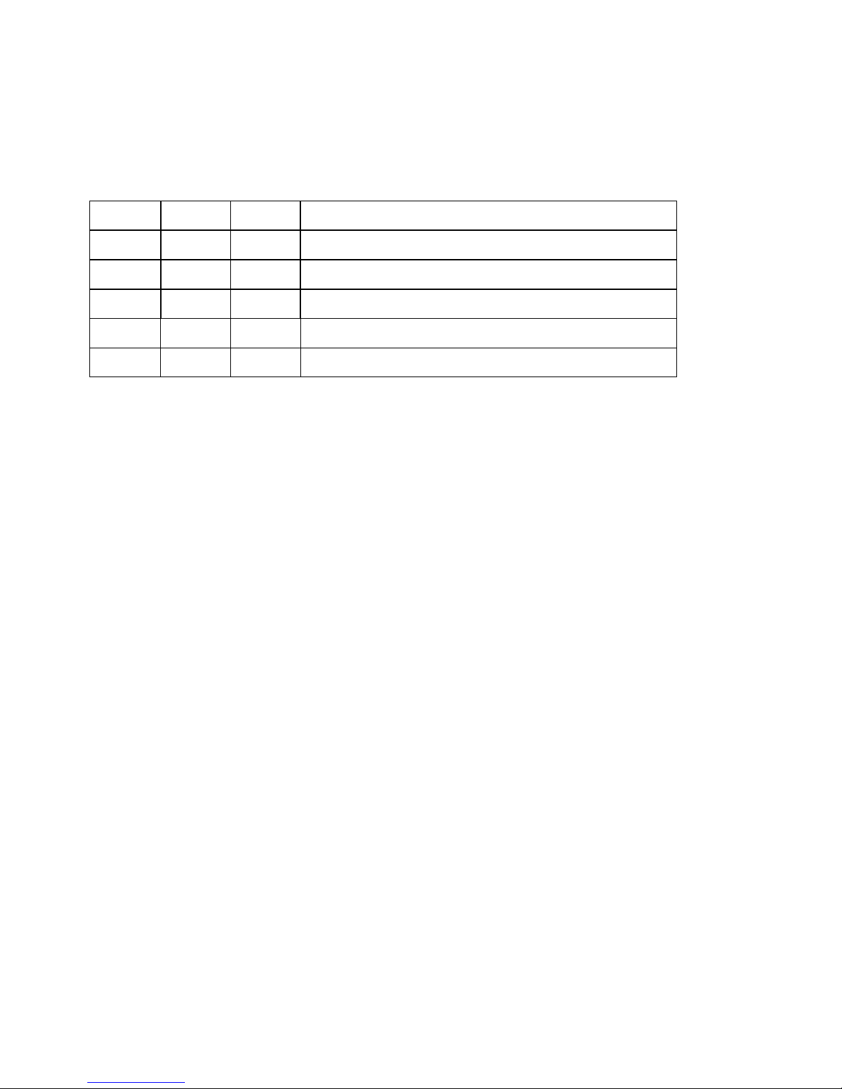
Current revision of this document is the uppermost in the table below.
Revision Replaces Date Change Description
2 1 27/02/03 Updated with new Thomson/GVG design.
1 0 30/01/01 Corrected error in baud rate setting
0 - 10/10/00 Initial Revision
Page 8

Page 9

BDS-0808 Rev. 2
1
1 General
The BDS-0808 is a 8x8 serial digital video router with vertical interval switching. This state of the art
router provides maximum quality with a data rate of up to 360Mbit/s and automatic cable equalizing on
all inputs. High performance circuits in SMD technology assure undiminished signal quality. The
BDS-0808 is well suited for all demanding routing tasks in digital studio and broadcast environments.
The built-in RS-232 interface allows the user to control the router via the Triton Router Control System
software with many operational features. The control bus technology allows linking the unit with the
BAS-0808 or BES-0808 to create an AFV router. One or several Triton remote control panels can control
the BDS-0808 as well. Another unique feature of the Triton 8x8 series is the possibility to reconfigure the
router via the configuration switch on the back plane to create several formats of routers:
8x8 Serial Digital Video 1 layer
4x4 Serial Digital Video 2 layer
2x2 Serial Digital Video 4 layer
1.1. Specifications
Data rate NRZ: 143Mbit/s - 360Mbit/s
VIT input: Comp. Video 1Vpp, 300mV sync, 75 ohms
Number of inputs: 8 terminated
Equalization: Automatic up to 300m ( Belden 8281 )
Number of outputs: 8
Impedance: 75 ohms
Return-loss: > 15dB (10MHz-270MHz)
Signal level: 800mV fixed on 75Ohm load
Connector: BNC
AC power: External power supply 100 - 260 VAC
DC power: +5V, connector DB9 male
Dimensions: 483 x 44 x 45 mm (19”, 1RU)
1.2. Connection drawing
Configuration switch
Video input section Video output section
NCB1
Power connector RS-232 port VIT input
1
Network Control Bus. The protocol of this bus is equal, and compatible to the MIDI bus protocol.
Page 10

BDS-0808 Rev. 2
2
2 Power connection
Do not connect mains to the desktop power supply before connecting the power supply to the
router.
Connect the DB9 female connector from the desktop power supply to the main unit. Tighten the screws to
assure a proper contact. To connect mains to the desktop power supply you need a mains cord with IEC
320 connector.
The BDS-0808 is normally delivered with the desktop power model AC ±5V / 30W. Upon customer
request, BDS-0808 can also be delivered with DC ±5V / 30W, which may be fed by a 36 – 72 VDC
mains power source. A Frame mounted power supply solution is also available.
Please refer to the latest Triton Product Catalogue for power supply types, or call Thomson Grass Valley
for this information.
If any third party power supply is used the BDS-0808 router requires +5V DC with a minimum current of
1.0A. The following pin-out is used on the DB9 male power connector:
Pin 1 0V
Pin 2 +5V
3 Connecting the BDS-0808 to your PC
For connection to a PC with Triton Router Control System, the RS-232 interface is used. The RS-232 port
on all Triton devices uses the standard DCE pin-out, see pin-out table under 4.3.
A standard modem cable can be used for connecting the router to the PCs serial port.
3.1 Selection of router level
The router level depends on the system configuration the router is going to work with. See chapter 5 for
more information. All routers are delivered with default level 1. Triton Router Control System offers the
control of up to 16 different routers or combinations of routers.
3.2 Pin-out of RS-232 connector
The DB9 female connector for the RS-232 port has the following pin-out:
Pin 2 Tx
Pin 3 Rx
Pin 5 GND
3.3 Maximum cable length
The maximum cable length for an RS-232 connection is per definition 15m. Longer distances can be
installed depending on the environmental conditions of the installation site. It is the responsibility of the
installer / user to secure a proper installation of the RS-232 connection.
Page 11

BDS-0808 Rev. 2
3
4 NCB connection
Via the Network Control Bus system several routers and control panels can be interconnected.
The standard MIDI interface is used on all NCB control ports. The BDS-0808 router utilises 5-PIN DIN
connectors for connecting to the NCB. This means that when you connect your BDS-0808 router to other
Triton devices, with RJ45 connectors, an RJ45 to 5-pin DIN interface is necessary.
This converter can be ordered from Thomson Grass Valley.
The NCB system allows connection of up to 16 routers with different levels on the same bus. Control
panels dedicated to work with a specific router must be configured to the same level as the router. Several
panels can work together with one specific router. Up to 16 single routers or combinations of routers can
be controlled from the Triton Router Control System. The NCB system and all RS-232 ports interchange
the system status.
4.1 Several routers in one system
The NCB system allows the interconnection of up to 16 routers with different levels in one system. A
combination of routers working married counts as one level. This might for example be 1 audio router + 1
video router working as an audio follows video system or 3 video routers working as an RGB (YUV)
system. The routers in such a constellation must be configured to the same level.
4.2 Connecting control panels
To get a control panel working with a specific router, configure the control panel to the same level as the
router. Several panels can be configured to control the same router. The Triton panels can control 2 levels
with breakaway function. If it is necessary to control more levels with breakaway an additional panel
must be used. Panels can also be connected to a router via the RS-232 interface. Please refer to your
control panel manual for installation.
Page 12

BDS-0808 Rev. 2
4
4.3 Pin-out and cable type
4.3.1 RJ45 connectors
On some Triton devices, the NCB cable can be connected to RJ-45 connectors. The following pin-out is
used:
Pin 1 = Not Connected
Pin 2 = Not Connected
Pin 3 = Not Connected
Pin 4 = data
Pin 5 = data
Pin 6 = Not Connected
Pin 7 = Not Connected
Pin 8 = Not Connected
4.3.2 5-pin DIN connectors
However, the pin-out of most Network Control Bus ports, including that of the BDS-0808 follows the
standard MIDI specification. A 1:1 cable with 5pin DIN connector is used. The following pin-out is used:
Pin 1 = Not Connected
Pin 2 = shield
Pin 3 = Not Connected
Pin 4 = data
Pin 5 = data
The standard MIDI specification recommends the use of shielded twisted pair cable types for
interconnection between the units.
Page 13

BDS-0808 Rev. 2
5
4.3.3 RJ45 to 5-pin DIN converter
In configurations that include both devices with RJ45 connectors, and devices with 5-pin DIN connectors,
an RJ45 to 5-pin DIN converter may be used to complete the control loop. This converter holds both
connector types, and may work both ways, thus from RJ45 to 5-pin DIN, as well as from 5-pin DIN to
RJ45.
The converter is connected as follows:
RJ45 (Router/CP) RJ45 (Converter) 5-pin DIN (Converter) 5-pin DIN (Router/CP)
IN IN IN OUT
OUT OUT OUT IN
4.4 Control bus structure
The Network Control Bus structure follows the standard MIDI bus definition. The NCB is defined as a
closed chain of units. This means that the NCB OUT of the last unit must be connected to the NCB IN of
the first unit in the NCB chain. To avoid problems with the control of Triton units the installer/user has to
assure that the bus structure is installed according to this definition. The total number of Triton devices in
an NCB chain is limited to 20.
4.5 Maximum distance between NCB devices
The standard MIDI definition allows a maximum cable length of 250 meters between two devices.
Longer distances can be made with MIDI repeater units. To avoid grounding problems all NCB ports
have opto-coupled inputs.
4.6 Control Bus configuration notes
In order to achieve a system that is easy to maintain and control, follow the important notes, presented
hereunder.
• Avoid using routers of different size, but same signal type (audio/video), on the same level.
Example: Do not configure a system with a BVS-1616 and a BVS-0808 on the same level. If they
were on the same level, crosspoint commands that were sent to the BVS-1616 lying outside the
range of the BVS-0808 would not be executed; the BVS-0808 would throw them off the bus.
However, a combination of a BVS-1616 and an BAS-0808 will work well, because commands are
different for video- and audio routers.
• Try to limit the number of devices on one Control Bus loop. If possible, separate systems that are
not to be controlled by one central control panel.
If you need to have several systems in one loop, try to separate as follows, using the DIP switches
on the rear of the devices:
o Analogue Video + Analogue Audio + CP for analogue system on Level 1
o SDI + AES/EBU + CP for digital system on Level 2
o RS-422 Data + CP for data on Level 3
Page 14

BDS-0808 Rev. 2
6
o Universal Control Panel to control all devices above, with user configurable default level.
• Pay attention to the figure below, in order to achieve full controllability of all devices in the loop.
Triton - RCS
• Complete the Control loop, by connecting all Control bus connections to all Triton devices, before
powering up any Triton device.
Page 15

BDS-0808 Rev. 2
7
5 Router configuration
5.1 Router level
Switch 1 - 4 on the configuration switch set the router’s level for communication with the Triton Router
Control System, and other units in the NCB system. The panels on the NCB dedicated to operate with the
router must be configured to the same level as that router.
If several routers are combined to form an audio follows video, RGB or similar system, these routers
must be configured to the same level.
The levels can be switched according to the following pattern:
- means switch down
* means switch up
Default level is 1.
Switch 1 2 3 4 Level
- - - - 1
- - - * 2
- - * - 3
- - * * 4
- * - - 5
- * - * 6
- * * - 7
- * * * 8
* - - - 9
* - - * 10
* - * - 11
* - * * 12
* * - - 13
* * - * 14
* * * - 15
* * * * 16
Page 16

BDS-0808 Rev. 2
8
5.2 Router mode
The BDS-0808 router allows switching in different modes. You can choose among:
8x8 Serial Digital Video 1 layer
4x4 Serial Digital Video 2 layer
2x2 Serial Digital Video 4 layer
Switch 5 - 6 on the configuration switch set the router’s mode. The Triton - RCS software must be
configured according to the mode chosen on the router.
The modes can be switched according to the following pattern:
- means switch down
* means switch up
Switch 5 6 Mode
- - Serial Digital Video 1 layer
- * Serial Digital Video 2 layer
* - Serial Digital Video 4 layer
* * position is not in use
Default mode is 8x8 Serial Digital Video 1 layer
Serial Digital Video 1 layer
SDV Signal Input SDV Signal Output
1 1 1 1
2 2 2 2
3 3 3 3
4 4 4 4
5 5 5 5
6 6 6 6
7 7 7 7
8 8 8 8
Serial Digital Video 2 layer
SDV layer 1 Input SDV layer 1 Output
1 1 1 1
2 2 2 2
3 3 3 3
4 4 4 4
SDV layer 2 Input SDV layer 2 Output
Page 17

BDS-0808 Rev. 2
9
5 5 5 5
6 6 6 6
7 7 7 7
8 8 8 8
Serial Digital Video 4 layer
SDV layer 1 Input SDV layer 1 Output
1 1 1 1
2 2 2 2
SDV layer 2 Input SDV layer 2 Output
3 3 3 3
4 4 4 4
SDV layer 3 Input SDV layer 3 Output
5 5 5 5
6 6 6 6
SDV layer 4 Input SDV layer 4 Output
7 7 7 7
8 8 8 8
5.3 Vertical interval trigger
The BDS-0808 router provides vertical interval switching. If vertical interval switching is desired you
have to connect an analogue VIT reference signal to the VIT input.
Switch 7 on the configuration switch enables or disables the VIT sensing on the VIT input. If VIT
switching is enabled but a proper signal is missing, the router will automatically switch without VIT.
The VIT can be switched according to the following pattern:
- means switch down
* means switch up
Switch 7 VIT
- disabled
* enabled
Default is VIT enabled.
Page 18

BDS-0808 Rev. 2
10
5.4 Power up mode
Switch 8 on the configuration switch defines the power up mode. The BDS-0808 router provides two
modes for powering up the system.
Mode 1 switches all outputs to input 1.
Mode 2 switches all outputs according to the buffered information in the routers processor system.
The power up reset can be switched according to the following pattern:
- means switch down
* means switch up
Switch 8 Power Up Reset
- Mode 2
* Mode 1
Default is Mode 2.
6 Connecting video signals to the BDS-0808
The BDS-0808 router offers standard 75 ohms BNC connectors for video in- and outputs. All video
inputs are terminated with 75 ohms.
Page 19

BDS-0808 Rev. 2
11
7 Control and connection of Triton systems, interface protocol
7.1 Important notes regarding the Triton Control Protocol
7.1.1 Binary Code
The strings shown on the next pages are in binary coded format. Please be aware of the fact that any
terminal program you may use to control a Triton unit from a PC must be able to generate hexadecimal
characters. ASCII characters will not be accepted.
7.1.2 Echo
A matrix will reply on a crosspoint set command with an ECHO. In the case where a crosspoint is already
set no ECHO will be sent. If the matrix is part of an NCB system two types of reply will be sent.
Immediately after receiving the crosspoint set command the ECHO will be sent. The matrix will then wait
for the command to pass the NCB system. After receiving the command from the NCB system the matrix
will send the command as an ACKNOWLEDGE.
7.1.3 RS-422 Matrixes
RS-422 Data Routers do not accept distribution of an input signal to several outputs. An input signal can
only be routed to one single output. The Firmware of our RS-422 routers takes care of these limitations. If
an input (Source) is already connected to a particular output (Destination) any connection of this input to
another output would disconnect the previous connection. The router will in this case send the following
message for the disconnected output: Output connected to input 128. Input 128 is an internal default for
the disconnect status. Please see Triton recommendations for use of RS-422 data routers for further
information.
7.1.4 Timeout
The Crosspoint Status Request message has a timeout, which means that you need to wait 1 second in
between request messages.
7.2 Basic principles
Any message on any level (address) that conforms to the standard arriving at either the NCB or the
RS232 port will be re-sent on both NCB and RS232. The only exceptions are:
a) A matrix that recognizes its address will not re-transmit the message if the crosspoint is already
set.
b) A matrix that recognizes its address will not re-transmit the message if the output number or input
number exceeds its size.
c) A unit (matrix or panel) will not re-transmit a message arriving at the NCB if it was re-transmitted
a short while ago (typically 0.5 sec). This is done by grabbing a message storing it for the timeout
period, and comparing it with new messages. After the timeout period the unit will grab a new
message for compare. This is done to remove unwanted (read: unknown) messages from the NCB
ring.
d) A message arriving at the RS232 will always be re-transmitted unless it is a matrix, and one of the
cases a) or b) is fulfilled.
7.2.1 Example: A single unit with no NCB connected
Messages sent to the RS232 of a single unit will be returned once no matter what address or input/output
number the message has, unless it is a matrix which recognizes one of the conditions a) or b) above.
Page 20

BDS-0808 Rev. 2
12
7.2.2 Example: Several units connected by NCB
Messages sent to the RS232 of a single unit will be returned once no matter what address or input/output
number the message has, unless it is a matrix which recognizes one of the conditions a) or b) above.
If none of the cases a) or b) is fulfilled the message will also be transmitted on the NCB. Then if any unit
on the NCB ring recognizes any of the cases a)/b) or c), the message will stop at that point. This means
that the message will only be returned once on the RS232.
However, if none of the units on the NCB recognizes any of the cases a) to c), the message will return to
the originator (the unit which received the message on RS232). This unit will re-transmit the message
once more on both NCB and RS232. The message is therefore returned a second time on RS232. This
time one of the cases a) or c) is sure to be identified by one of the units on the NCB, and the message is
removed.
There is however one more special case: If several messages for unused addresses are transmitted with
only little delay, one might experience that some messages are returned several times, as the
store/compare/remove function in case c) can only handle a single message at the time. We therefore
recommend that the user avoid sending messages to unused addresses.
7.3 RS232
The RS-232 port is used for external control of Triton units. The RS-232 port allows the customer to
control the equipment via the Triton Router Control System PC program or self-defined customized
solutions.
Connector for the RS-232 port is a DS9 female.
Pin 2 - Tx.
Pin 3 - Rx
Pin 5 - GND
A standard DCE (Data Communication Equipment) cable can be used for connection between PC and
Triton equipment. The connection between the connectors is made one-to-one.
Data-rate is 19200 baud/sec with 8 data-bit, 1 stop-bit, no parity, if nothing else is specified in the user
manual of the product.
7.4 NCB
The NCB is used for interconnection between several Triton units. Up to 20 routers and/or control panels
can be linked together to form a routing system with many operational features.
The NCB utilises a 5 mA current loop with opto-coupled ports.
Standard connector is a 5pin DIN.
Standard MIDI cables can be used to interconnect several Triton units.
Data-rate is 31.25 Kbps.
1 start-bit, 8 data-bit, no parity, 1 stop-bit. Logical 0 = current ON.
Page 21

BDS-0808 Rev. 2
13
7.5 Commands
7.5.1 Audio crosspoint set
Only for use with Audio routers.
Command for setting of crosspoints:
1001nnnn 0kkk kkkk 0vvv vvvv
- nnnn is the matrix address from 0 up to 15.
- kkk kkkk is the output which shall be controlled.
kkk kkkk = output number
0 = output 1
127 = output 128
- vvv vvvv is the input which shall be connected to the chosen output.
vvv vvvv = input number
7.5.2 Audio crosspoint set acknowledge
Only for use with Audio routers.
Command for acknowledging setting of crosspoints:
1000nnnn 0kkk kkkk 0vvv vvvv
- nnnn is the matrix address from 0 up to 15.
- kkk kkkk is the output which shall be controlled.
kkk kkkk = output number
0 = output 1
127 = output 128
- vvv vvvv is the input which shall be connected to the chosen output.
vvv vvvv = input number
7.5.3 Video crosspoint set
Only for use with Video routers.
Command for setting of crosspoints:
1010nnnn 0kkkkkkk 0vvvvvvv
- nnnn is the matrix address from 0 up to 15.
- kkk kkkk is the output which shall be controlled.
kkk kkkk = output number
0 = output 1
127 = output 128
- vvv vvvv is the input which shall be connected to the chosen output.
vvv vvvv = input number.
Page 22

BDS-0808 Rev. 2
14
7.5.4 Video crosspoint set acknowledge
Only for use with Video routers.
Command for acknowledging setting of crosspoints:
1011nnnn 0kkkkkkk 0vvvvvvv
- nnnn is the matrix address from 0 up to 15.
- kkk kkkk is the output which shall be controlled.
kkk kkkk = output number
0 = output 1
127 = output 128
- vvv vvvv is the input which shall be connected to the chosen output.
vvv vvvv = input number.
7.5.5 Crosspoint status request
This command is used for status request on Audio and Video routers.
1100nnnn 0xxxxxxx
- nnnn is the matrix address from 0 up to 15.
- xxxxxxx - do not carry any information
The requested router (Audio or Video) will send its crosspoint status on NCB OUT and RS232. The same
command format as for crosspoint set is used.
 Loading...