

Page 1

Texas
Instruments
TravelMate 2000
Notebook Computer
User’s Manual
Page 2

Contents
Preface.................................................................................................... v
1 Taking a First Look
The Hardware......................................................................................1-3
TravelMate 2000 Options....................................................................1-7
The Software......................................................................................1-10
The Hard Disk....................................................................................1-11
2 More About Hardware
LCD Screen..........................................................................................2-3
Right Side Panel...................................................................................2-6
Left Side Panel.....................................................................................2-7
Rear Panel............................................................................................2-9
Bottom Panel......................................................................................2-11
Front Panel.........................................................................................2-12
Keyboard ...........................................................................................2-13
Status Indicators.................................................................................2-19
3 Setting Up
Guidlines & Precautions......................................................................3-2
Installing the Battery ............................................................................3-3
Removing the Battery...........................................................................3-5
Charging the Battery/AC Operation .....................................................3-7
Setting DIP Switches............................................................................3-9
4 Getting Started
System Start-up....................................................................................4-4
Accessing the Set Up Screen................................................................4-6
Making Selections on the Set Up Screen..............................................4-8
Set Up Screen Fields............................................................................4-9
Setting Up the LCD ............................................................................4-14
Displaying the Hardware
Installation Screen.....................................................................4-18
Making Selections on the Hardware
Installation Screen.....................................................................4-20
Hardware Installation Screen Fields..................................................4-21
Restarting the System.........................................................................4-25
Backing Up the Hard Disk..................................................................4-26
Page 3

5 Application Programs
Guidelines for Installing Applications..............................................................................5-3
LapLink...........................................................................................................................5-10
Laptop Manager..............................................................................................................5-13
Using the Password Utility..............................................................................................5-15
6 TravelMate 2000 Options
Add-On Battery Pack........................................................................................................6-2
3.5-inch Floppy Drive Unit...............................................................................................6-5
Numeric Keypad.............................................................................................................6-10
RAM Card ..................................................................................................................6-12
CRT ..................................................................................................................6-16
External Monitor.............................................................................................................6-18
2400 BPS Modem with Send-Fax
and MNP Class 5.....................................................................................................6-19
80C287 Coprocessor......................................................................................................6-20
External Keyboards.........................................................................................................6-24
Printers ..................................................................................................................6-25
Appendices
Specifications ..................................................................................................................A-1
Taking Care of Your Computer........................................................................................B-1
Character Sets..................................................................................................................C-1
Keyboard Layouts............................................................................................................D-1
Diagnostics ................................................................................................................... E-1
Troubleshooting................................................................................................................F-1
BIOS Messages................................................................................................................G-1
Configuring Memory........................................................................................................H-1
Connector Pin Assignments................................................................................................I-1
Screen Standards...............................................................................................................J-1
Restoring MS-DOS System Files.....................................................................................K-1
Warranty and Service........................................................................................................L-1
Contents
Table of Contents iii
Glossary
Index
Page 4

Copyright(C) 1990 Texas Instruments Incorporated
All Rights Reserved - Printed in U.S.A
TravelMate 2000 Personal Computer, User's Manual Part No. 2568084-0001
Original Issue: July 1990 Revision C: January 1991
Changes may be made periodically to the information in this publication. Such changes will be incorporated in new editions of
this manual.
Record the serial number, purchase date, and model number in the spaces provided below. The serial number and model
number are recorded on the label affixed to the case. AR correspondence concerning your unit should include the serial
number, model number, and date of purchase.
TravelMate 2000 Personal Computer:
Serial Number: Purchase Date:
No part of this publication may be reproduced, stored in a retrieval system, or transmitted in any form or by any means,
electronic, mechanical, photocopy, recording, or otherwise, without the prior written permission of Texas Instruments
Incorporated.
The equipment, as well as the programs that TI has created to use with them, are tools that can help people better manage the
information used in their business. But tools-including TI products--cannot replace sound judgment nor make the manager's
business decisions.
Consequently, TI cannot warrant that its products are suitable for any specific customer application. The manager must rely on
judgment of what is best for Ms or her business.
TravelMate and BatteryPro are trademarks of Texas Instruments incorporated. BitCom and BitFax are trademarks of BIT Software, Inc.
Hayes is a registered trademark and Hayes SmartModem 2400 B is a trademark of Hayes Microcomputer Products Inc.
IBM PC, XT, AT and PS/2 are trademarks of International Business Machines Corporation.
Intel is a trademark of Intel Corporation.
LapLink is a trademark of Traveling Software, Inc.
Lotus is a trademark of Lotus Development Corporation.
Microcom Is a trademark and MNP is a registered trademark of Microcom, Inc.
Microsoft, MS-DOS, SHELL, and InPort Mouse are trademarks of
Microsoft Corporation.
Page 5

Preface
Congratulations ... you have purchased one of the most powerful notebook computers available, the Texas Instruments
TravelMateTM 2000 Computer.
The TravelMate 2000 is a lightweight, full-function computer with the features and power of many desktop personal computers,
including a 20-megabyte internal hard disk drive, an 80C286 microprocessor, built-in MS-DOS
TM
4.01, built-in LapLink
TM
file
transfer utility that connects your TravelMate 2000 to another computer, and many options to make your TravelMate 2000 more
powerful and specialized for your particular applications.
Note:
4.01, GW-BASIC, Laptop Manager, Laptop File Manager, power-up diagnostics, and other utilities.
Your new TravelMate 2000 hard disk drive and the built-in ROM are already formatted and loaded with MS-DOS
format the hard
Do not
disk (drive C) or you will delete these programs. However, these programs also are included on the floppy disk furnished
with your new computer so that you can restore the programs to the hard disk if necessary. Any data entered by you into the
computer will be lost forever if you reformat the hard disk unless you have backed up the data on floppy diskettes.
Your TravelMate 2000 accepts a variety of options, including an external 3.5-inch Floppy Drive Unit, CRT Adaptor, Internal
Modem, 80C287 Coprocessor, Add-On Battery Pack, Expansion Unit, RAM expansion cards, Numeric Keypad and printers,
available from Texas Instruments. Contact your distributor or telephone TI-Express, 1-800-TI PARTS.
v
Page 6

Preface
When you open the container in which your computer is packaged, you will find the following items:
Computer
Battery
AC Adaptor
AC Cord
Parallel Port Conversion Adaptor
User's Manual (this manual)
LapLink Cable
LapLink File Transfer Utility and Device Driver User’s Manual
MS-DOS User’s Manual
BatteryPro
Two Function Key template strips
If any of the above items are missing, contact your Texas Instruments dealer.
vi
TM
and Productivity Software User’s Manual and floppy diskette
Page 7
Preface
Conventions and Symbols
Throughout this manual, the following conventions are used to distinguish elements of text:
SMALL CAPS Used for commands, options, switches, and literal portions of syntax that must appear exactly as
shown
italic Used for filenames, variables, and placeholders that represent the type of text to be entered by the
user
Monospace Used for sample prompts and screens that appear during operation of your computer, including
prompts (text generated by the system) and entries that you type on the keyboard
Bold
Several international symbols are used throughout this manual to advise you of important information.
This symbol indicates a
your TravelMate 2000.
This symbol alerts you to a
your equipment.
This symbol tells you that more information about the same subject is contained on the next page.
Used for keys, key sequences, and MS-DOS prompts
concerning operating procedures or information you should know to help you operate
Note
Warning
or
Caution
that can prevent you from causing injury to yourself or damage to
-
vii
Page 8

Preface
About this Manual
This manual describes the operation of your Texas Instruments TravelMate 2000 Notebook Computer. We have designed this
manual so that you can locate information quickly and easily. Each chapter begins with a title page that gives the major sections
in the chapter.
Keyboard keys are listed several ways in this manual, depending on the number of keys you must press to produce a character
or function. For example, some key fronts on the keyboard are labeled with blue to indicate their use only in conjunction with
the
key.
Fn
Some keys (for example,
perform their action. The text in this manual refers to these keys according to their function, preceded by the additional key you
must also press. Software programs use various key combinations; refer to your software program manual for specific
information.
The word floppy is used in this manual to refer to diskettes, microdiskettes, disks, and other terms commonly used to describe a
removable, nonvolatile, magnetic-media diskette. The words disk and diskette are used in direct quotations, for example, in
describing a displayed error message, setup menu, etc.
Break
and
Num Lk)
must be pressed in conjunction with another key (for example,
Ctrl
and
Fn)
to
Contents of this Manual
Here is an overview of what to expect in each chapter:
Chapter 1 - Taking A First Look
computer and a simple technical overview of the TravelMate 2000 and its options. Experienced users may only need to skim
this chapter.
Chapter 2 - More About Hardware
viii
gives users who are not familiar with computers some basic information about the parts of a
describes the TravelMate 2000's hardware features and explains how they work.
Page 9

Preface
Chapter 3 - Setting Up
Chapter 4 - Getting Started
Chapter 5 - Installing and Using Application Programs
2000, including the MS-DOS and GW-BASIC firmware and the LapLink and Laptop Manager utilities.
Chapter 6 - TravelMate 2000 Options
2000-Add-On Battery Pack, 3.5-inch Floppy Drive Unit, Numeric Keypad, RAM Card, CRT Adaptor, Internal Modem,
80C287 12 MHz Coprocessor, external keyboards, CRT monitors, and printers.
Appendix A -Specifications
Appendix B - Taking Care of Your Computer
your battery and conserving battery power.
Appendix C - Character Sets
Appendix D - Keyboard Layouts
the
Num Lock
Appendix E - Diagnostics
properly.
Appendix F - Troubleshooting
key, and the IBM Enhanced keyboard.
tells you what to do to get your TravelMate 2000 ready for operation.
shows how to customize the TravelMate 2000 for your own special needs.
tells you about the software that comes installed in your TravelMate
describes the use of options that can improve the performance of your TravelMate
lists operating and environmental specifications for your TravelMate 2000.
provides information for cleaning your TravelMate 2000, as well as caring for
illustrates and describes U.S. and international character sets used by the TravelMate 2000.
illustrates the characters generated by the standard U.S. keyboard and using the
describes the diagnostics routines that are available to ensure your TravelMate 2000 is functioning
describes problems that can occur with your TravelMate 2000 and what to do about them.
Fn
key and
ix
Page 10

Preface
Appendix G - BIOS Messages
Appendix H - Configuring Memory
computer.
Appendix I - Connector Pin Assignments
TravelMate 2000.
Appendix J - Screen Standards
TravelMate 2000.
Appendix K - Restoring MS-DOS Files
ROM.
Appendix L - Warranty and Service
TravelMate 2000 require service.
A
Glossary
of frequently used technical terms and an
lists the error messages you may encounter and what to do about them.
illustrates the TravelMate 2000's memory map and describes the memory options of the
lists the standard and expanded characteristics of the various displays supported by the
describes the standard warranty and outlines the procedure to follow should your
lists the signals produced by the standard and optional connectors on the
describes the procedure for reinstalling MS-DOS system files to the hard disk from
are included near the end of the manual to help you.
Index
x
Page 11

Preface
What to Read
Before performing any of the tasks below, we recommend you read the corresponding chapter(s) in this manual.
Quick start - Chapters 3 and 4
Setting up the TravelMate 2000 - Chapters 1 and 3
Using the operating system - Chapter 4
Using options - Chapters 1 and 5
Troubleshooting and general care of the computer Chapter 1 and Appendices
Other Manuals About the TravelMate 2000
The following manuals are furnished with your new TravelMate 2000 to help you operate and maintain your computer and its
optional devices.
Title Part Number
BatteryPro
LapLink File Transfer and Device Driver 2568087-0001
MS-DOS User’s Manual 2568085-0001
TM
and Productivity Software 2568090-0001
User's Manual
User's Manual
xi
Page 12

Taking A First Look
This chapter tells you about:
Computer hardware such as the system main circuit board, the display, and the keyboard
Options for your TravelMate 2000
Software operating systems and application programs
Caring for the Hard Disk
Contents
The Hardware...................................................................................................................1-3
System Board.............................................................................................................1-4
Microprocessor .........................................................................................................1-4
RAM..........................................................................................................................1-5
ROM ....................................................................................................................1-5
Keyboard...................................................................................................................1-5
LCD Screen ...............................................................................................................1-6
Hard Disk ..................................................................................................................1-6
Connectors.................................................................................................................1-6
TravelMate 2000 Options.................................................................................................1-7
Add-On Battery Pack.................................................................................................1-8
3.5-inch Floppy Drive Unit........................................................................................1-8
Numeric Keypad........................................................................................................1-8
1 M byte RAM Card..................................................................................................1-8
CRT Adaptor.............................................................................................................1-9
2400 BPS Modem with Send-Fax
and MNP Class 5 (Internal Modem)...................................................................1-9
80C287 12 MHz Coprocessor...................................................................................1-9
Printers ....................................................................................................................1-9
External Keyboards ...................................................................................................1-9
1
Taking a First Look 1-1
Page 13

Contents
1-2 Taking a First Look
The Software...................................................................................................................1-10
The Hard Disk ...................................................................................................................1-11
Hard Disk Format........................................................................................................1-11
Taking Care of the Hard Disk.......................................................................................1-11
Page 14
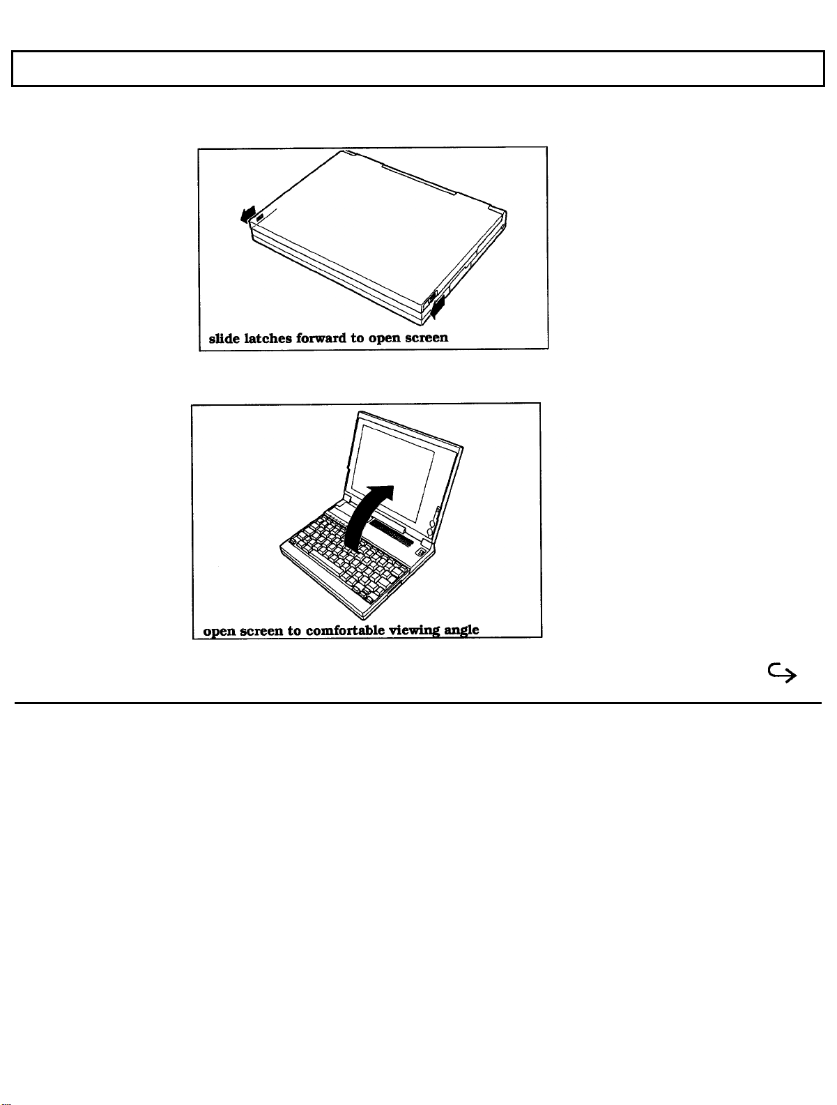
This is what the standard TravelMate 2000 Computer looks like when it is closed.
Here's how the TravelMate 2000 looks when it is set up and ready to operate.
The Hardware
Taking a First Look 1-3
Page 15

The Hardware
Let's take a closer look at each part of the computer.
The TravelMate 2000's hardware consists of a system board, keyboard, liquid crystal display (LCD) screen, hard disk
drive, I/O (input/output) ports, and other electronic circuits needed to control the display and externally connectable
options.
System Board
The system board carries integrated circuits that make up the microprocessor and memory. The system board also
contains hardware that controls the screen and keyboard. The optional RAM cards, CRT Adaptor, Internal Modem,
and 80C287 coprocessor plug into the system board.
Microprocessor
The microprocessor is the "brain" of the computer. It processes data-or information-at speeds so fast, its performance
is measured in millionths of a second. The microprocessor handles information in binary code, using the digit 0 or 1.
Any piece of information (e.g., a number or character) is represented by a string of 0's and 1's. For example, the
number 23 in binary is 1 0 1 1 1. A 0 or 1 in the binary system is referred to as a bit, the smallest piece of information
handled by the processor. A byte is a group of eight bits, and represents a single character or number, such as "H" or
"9". The microprocessor in the TravelMate 2000 is a high-speed 80C286 microprocessor, running at a clock speed of
up to 12 MHz.
1-4 Taking a First Look
Page 16

The Hardware
RAM
RAM (Random Access Memory) stores data and application software for the processor. You can write to or read
from RAM freely, but once the power is turned off, the data in RAM is lost. RAM size is described by the amount of
information (bytes) it can store. Symbols often used for this are "K" and "M". One K byte 1 K byte) represents 1024
bytes and one M byte (1 M byte) represents 1024 K bytes. The TravelMate 2000 has a standard RAM size of 1 M
byte. This can be increased to 3 M byte by installing two optional 1 M byte RAM cards.
ROM
ROM (Read-Only Memory) contains factory-programmed information, which remains stored even with the power off.
You can never change the contents of ROM. The TravelMate 2000 has two ROM areas. One stores the IPL (Initial
Program Loader), BIOS (Basic Input/Output System), and setup and hardware installation functions. These programs
are sometimes referred to as firmware. The other ROM area stores the diagnostics program, LapLink program, and
the operating system, MS-DOS 4. 0 1. This area is called a ROM disk and is used to install MS-DOS on the hard disk.
Keyboard
You communicate with the computer by typing on the keyboard. Many of the keys work just like those on a regular
typewriter. However, as you will see, some of the keys have special functions not available on a typewriter. The
TravelMate 2000 keyboard is modeled after the IBM 10l/ 102 -key enhanced keyboard layout.
Taking a First Look 1-5
Page 17

The Hardware
LCD Screen
The LCD screen acts as a window where the computer sends information for you to view. Information entered on the
keyboard, read from the hard disk or a floppy, or sent via a modem, for example, is displayed on the screen. The
TravelMate 2000's LCD screen can be set to emulate industry standard display modes, including the VGA mode used
by IBM in its latest PS/2 series of personal computers, and displays colors as 16 shades of gray. The illuminated,
triple supertwist, LCD screen gives you maximum readability in all lighting conditions with a true black-on-white
display.
Hard Disk
The hard disk can store up to 20 M byte of information the equivalent of about 14 high-density floppies-and can write
and read data very quickly. This makes the hard disk the best place to keep the programs that you use most frequently.
Connectors
The parallel port is used to connect a parallel printer via the supplied conversion adaptor, and the serial RS-232C
port is used to connect an external modem, a serial printer, and other devices that use a serial connector. An
expansion bus connector is used to connect the optional Expansion Unit (TI Part No. 2568032-0001) or 3.5-inch
Floppy Drive Unit RI Part No. 2568031-0001) to the computer. A numeric keypad connector is used to connect the
optional Numeric Keypad (TI Part No. 2568033-0001) to the computer. The external battery connector is used to
connect the Add-On Battery Pack (TI Part No. 2568030-0001) to the computer.
1-6 Taking a First Look
Page 18

TravelMate 2000 Options
The performance of a standard TravelMate 2000 can be enhanced with the addition of hardware options available
from Texas Instruments. These options enable you to send and receive data over telephone lines, operate the computer
for longer periods, use external displays, increase memory, and a variety of other features.
TravelMate 2000 Options
The following hardware options are available from your Texas Instruments dealer or TI-Express, 1-800-TI-PARTS,
for use with the standard TravelMate 2000 to expand its capabilities. See Chapter 6 for information about installing
these options.
Add-On Battery Pack (TI Part No. 2568030-0001)
1.44 M byte 3.5-inch Floppy Drive Unit (TI Part No. 2568031-0001)
Expansion Unit (TI Part No. 2568032-0001)
Numeric Keypad (TI Part No. 2568033-0001)
1 M byte RAM Card (TI Part No. 2568034-0001)
CRT Adaptor (TI Part No. 2568035-0001)
2400 bps Modem with send FAX capabilities and MNP Class 5 (TI Part No. 2566941-0001)
80C287 12 MHz Coprocessor (TI Part No. 2560874-0001)
Deluxe carrying case (TI Part No. 2568069-0001)
Extra Internal Battery Pack (TI Part No. 2568094-0001)
Taking a First Look 1-7
Page 19

TravelMate 2000 Options
Laser and impact Printers
External Keyboards
Add-On Battery Pack
Attaching the optional Add-On Battery Pack to the rear of the TravelMate 2000 adds 3 hours to the operating time.
When the Add-On Battery Pack is installed, you cannot use the 3.5-inch Floppy Drive Unit or the Expansion Unit.
3.5-inch Floppy Drive Unit
Using the 3.5-inch Floppy Drive Unit allows you to store information on 1.44 M byte floppies. The 3.5-inch Floppy
Drive Unit also has a port with which you can install a 5.25-inch floppy drive, not available from Texas Instruments,
and an external keyboard as well.
Expansion Unit
Connecting the Expansion Unit allows you to expand the capabilities of your TravelMate 2000 Computer. The
Expansion Unit supports one full-size and one half- size expansion card.
Numeric Keypad
1-8 Taking a First Look
Connecting the Numeric Keypad allows you to enter numeric data easily. The Numeric Keypad is laid out like the
numeric keypad on an IBM keyboard.
1
M byte RAM Card
Using one or two RAM cards allows you to increase the amount of random access memory in your TravelMate 2000.
The memory on these cards can be used as Extended memory or as Expanded memory conforming to version 4.0 of the
Lotus/Intel/Microsoft Expanded Memory Specifications.
Page 20

TravelMate 2000 Options
CRT Adaptor
Installing the CRT Adaptor into the computer allows you to connect a VGA or multi frequency monitor to the
TravelMate 2000.
2400 BPS Modem with Send-Fax and
MNP Class 5 (Internal Modem)
Installing the internal modem card in the TravelMate 2000 allows you to send Facsimile (fax) information over
telephone lines.
Note:
manual provided with the option.
The Internal Modem Card may not be available in some countries. For information on this option, see the
80C287 12 MHz Coprocessor
Adding an 80C287 coprocessor to the system board significantly improves processing performance when you are
running programs that support a math coprocessor.
Printers
Connecting a printer to your TravelMate 2000 allows you to produce a hard copy of information you have created. To
connect a parallel printer, use the supplied conversion adaptor between the parallel port and the TravelMate 2000
printer port. To use a serial printer, simply connect the printer to the serial port of the TravelMate 2000.
External Keyboards
Using the 6-pin mini DIN connector on the 3.5-inch Floppy Drive Unit allows you to connect an additional IBM PS/2
or equivalent keyboard.
Taking a First Look 1-9
Page 21

The Software
A computer system needs software before it can carry out any useful task. Without software, your computer is just a
collection of electrical components. In order to use computer hardware for tasks like writing memos or balancing a
checking account, software is necessary.
Software is a series of instructions that direct the computer to perform specific tasks. Generally, these instructions are
loaded from a floppy or a hard disk into main memory where they remain until the software program is exited or the
system is turned off.
Your computer needs three levels of software to function - an input/output system, an operating system, and an
application program.
The BIOS (basic input/output system) is stored in ROM on the system board. The BIOS controls the
input/output functions of the hardware itself, according to information received from the operating
system or software program, also known as BIOS calls.
The operating system is a software program that manages the computer's resources, such as disk
drives and printers. By performing these general routines, the operating system is the base on which
programming languages like GW-BASIC and application programs run. The operating system for
this computer is MS-DOS, version 4.01, and is stored in the ROM disk and on the hard disk.
An application program is software that helps you perform business and personal tasks such as
word processing, spreadsheet analysis, and graphics presentations. Almost all of the application
programs written to run with MS-DOS on IBM and compatible personal computers can be used with
the TravelMate 2000.
1-10 Taking a First Look
Page 22
The Hard Disk
The hard disk is a permanently installed magnetic disk. Information is read from and written to both sides of the disk
at extremely high speeds by heads that float above the disk surface on a cushion of air. When the disk is not actually
being used, these heads automatically "park" themselves out of the way to prevent the disk surface from being damaged
by head movement.
Hard Disk Format
The hard disk has a platter, which is divided into cylinders. A cylinder is a collection of tracks in the same position
on different sides of the hard disk platters.
The tracks of each cylinder are further divided into sectors. Each sector is numbered and holds 512 bytes of data.
The computer locates data on the disk by looking for its sector number.
The hard disk in the TravelMate 2000 is formatted and loaded with software by Texas Instruments during assembly.
Do not
format the hard disk.
Caution: If you format the hard disk, all data on the hard disk will be lost.
Taking Care of the Hard Disk
The hard disk in your TravelMate 2000 computer is specially designed to withstand the rigors of travel: the hard disk
heads automatically park themselves when the computer is turned off. However, it is still a precision device and
careful treatment will prolong its life.
Follow these guidelines to get the most out of your hard disk's performance:
Never move the computer when the hard disk is being accessed.
Taking a First Look 1-11
Page 23

The Hard Disk
Never subject the computer to strong vibration or sudden shocks, especially during
transportation.
You can move your computer with the power on; however, it is a good idea to put the
computer in Standby mode.
Always keep backup floppies of all programs and data stored on your hard disk, just in
case of a hard disk failure. The time spent backing up your data is always worthwhile.
Caution:
because of a hard disk failure. Follow the MS-DOS backup procedure in your MS-DOS manual or use a
backup procedure provided by your application program. If your hard disk fails, TI service personnel may or
may not be able to save some or most of the contents of your hard disk if replacement Is required.
When moving your computer to a location where the temperature is more than 18o F (10o C different
from the present location, do the move in two stages: first leave the computer in a place where the
temperature is somewhere between that of the new location and the old location for about 1 hour.
Then move the computer to the new location. This ensures that the hard disk mechanisms have time
to adjust to the new environment and prevents moisture from condensing on the vital parts.
In case of a hard disk failure, contact Texas Instruments at 1-800-847-5757 for information about
data recovery.
You
should back up your hard disk to floppies on a regular basis to protect against loss of data
1-12 Taking a First Look
Page 24

This chapter tells you about:
2
More About Hardware
Your LCD screen and how to adjust it
Controls and connectors on the sides of the TravelMate 2000 case
Common keyboard key assignments
Indicators and their meanings
Contents
LCD Screen ....................................................................................................................2-3
Resolution..................................................................................................................2-3
Screen Angle..............................................................................................................2-4
Backlight....................................................................................................................2-4
Standard/Reverse Switch...........................................................................................2-4
Contrast Control.........................................................................................................2-5
Brightness Control.....................................................................................................2-5
Right Side Panel................................................................................................................2-6
Numeric Keypad Connector.......................................................................................2-6
Security Hook Holder................................................................................................2-6
Left Side Panel..................................................................................................................2-7
Parallel (Printer) Port................................................................................................2-7
LCD/CRT Switch ......................................................................................................2-8
Serial (RS-232C) Port...............................................................................................2-8
Rear Panel ....................................................................................................................2-9
Expansion Bus Connector..........................................................................................2-9
Add-On Battery Pack Connector................................................................................2-9
AC Adaptor Jack .....................................................................................................2-10
Bottom Panel2-11
Battery Slot..............................................................................................................2-11
Front Panel ..................................................................................................................2-12
Power Switch ..........................................................................................................2-12
Optional Card Slot Cover........................................................................................2-12
More About Hardware 2-1
Page 25

Contents
Keyboard ........................................................................................................................2-13
Enter Key.................................................................................................................2-14
Shift .........................................................................................................................2-14
Caps Lock................................................................................................................2-14
Tab ..........................................................................................................................2-15
Backspace................................................................................................................2-15
Ctrl ..........................................................................................................................2-15
Alt ..........................................................................................................................2-15
Alt Gr.........................................................................................................................2-15
Fn ...........................................................................................................................2-15
Cursor Control Keys....................................................................................................2-16
Esc ...........................................................................................................................2-16
Function Keys.............................................................................................................2-16
Ins (Insert)..................................................................................................................2-16
Del (Delete)................................................................................................................2-17
Num Lk......................................................................................................................2-17
Scr Lk........................................................................................................................2-17
Pause.........................................................................................................................2-17
Break.........................................................................................................................2-17
Sys Rq .......................................................................................................................2-17
Prt
SC........................................................................................................................
Set Up........................................................................................................................2-18
Status Indicators.................................................................................................................2-19
Power ........................................................................................................................2-19
Low Battery................................................................................................................2-19
Charge........................................................................................................................2-19
Floppy Disk................................................................................................................2-19
Hard Disk...................................................................................................................2-20
Caps Lock..................................................................................................................2-20
Num Lock..................................................................................................................2-20
Scroll Lock.................................................................................................................2-20
2-18
2-2 More About Hardware
Page 26
LCD Screen
Your TravelMate 2000 displays text and graphics on a triple supertwist, illuminated, liquid crystal display
(LCD), giving true black-on-white contrast. The TravelMate 2000 can emulate IBM's video graphics array
(VGA), and it displays colors as 16 shades of gray.
You also can connect an external monitor to the TravelMate 2000 if the optional CRT Adaptor is installed.
External monitor options are described in TravelMate 2000 Options" in Chapter 6.
Resolution
The screen displays a maximum resolution of 640 dots horizontally by 480 dots vertically. The actual
display resolution depends on which display mode you select on the Hardware Installation screen and the
display mode your application program is designed to use.
The display adaptor in the TravelMate 2000 allows you to select display modes for the LCD screen. (See the
Hardware Installation Screen described in Chapter 4.)
More About Hardware 2-3
Page 27

LCD Screen
Screen Angle
The LCD screen can be adjusted for the best viewing angle, but be careful not to tilt the screen more than
necessary. Appropriate angles are 90' to 132' from horizontal.
Caution: To ensure safety and save battery, power, an alarm sounds for about 90 seconds
when the screen is closed with the power on. The TravelMate 2000 is designed so that it can be used
with the screen closed, for Instance, when running a demonstration program with an external monitor.
Nevertheless, never transport the computer with the power on.
Backlight
The illuminated screen allows you to control background brightness for better readability. The backlight
goes on automatically when the computer is turned on. To conserve battery power, the backlight can be
automatically turned off if there is no activity for a certain length of time: this time period can be set on the
Set Up screen described in Chapter 4. Pressing any key on the keyboard turns the backlight on again.
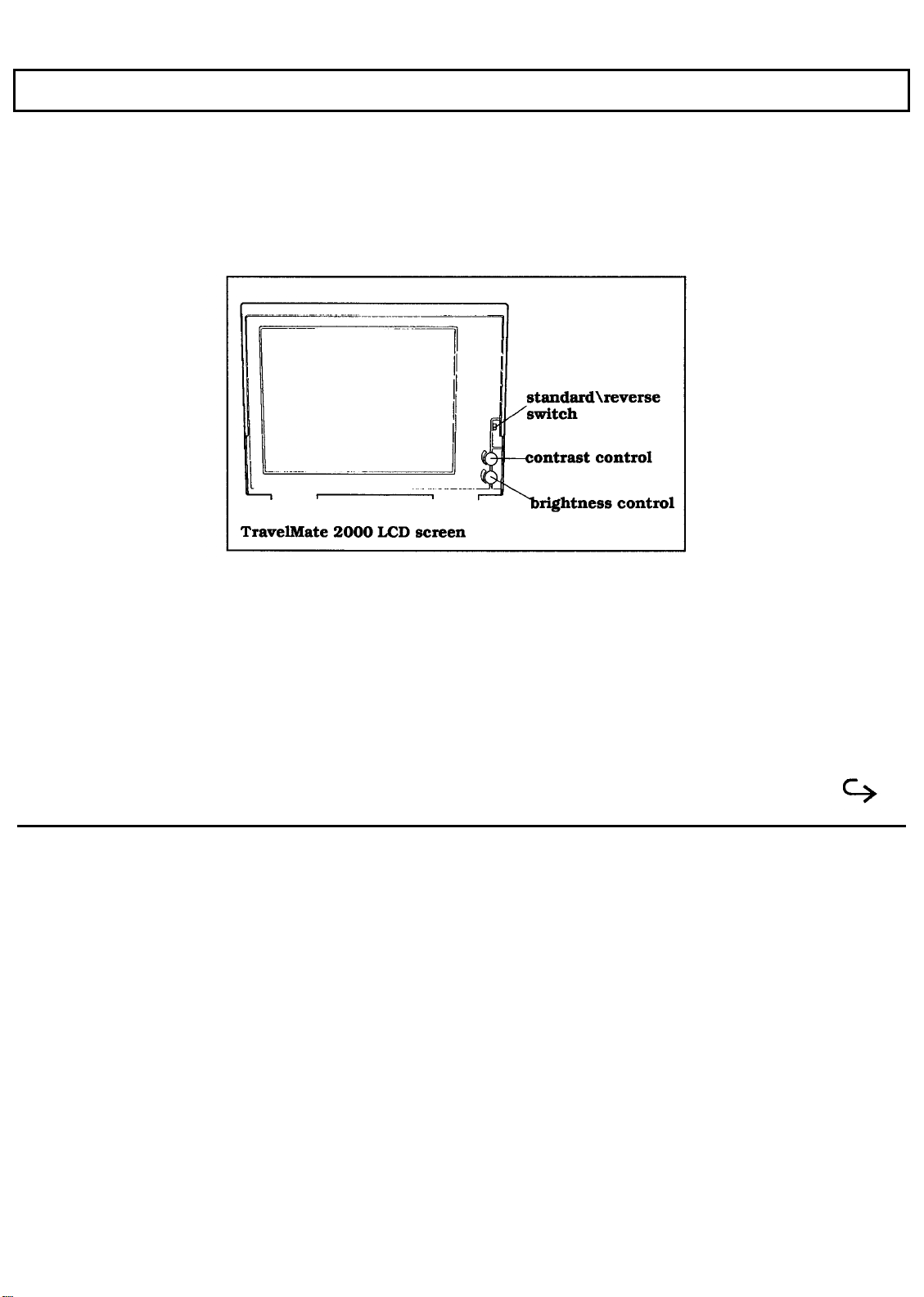
Standard/Reverse Switch
The screen normally displays black characters on a white background. You can reverse this to display white
on black by changing the setting of the Standard/Reverse switch on the right of the screen panel from Standard
to Reverse.
2-4 More About Hardware
Sometimes graphic images display like a photographic negative on the LCD screen. Reversing the display
should correct this effect. You can change this setting with the power on.
Page 28

LCD Screen
Contrast Control
The Contrast Control adjusts the contrast between the displayed information and the background for the best
viewing condition. Use in conjunction with the Brightness Control.
Brightness Control
The Brightness Control adjusts the brightness of the illuminated display. Use in conjunction with the Contrast
Control.
Note:
consumption. To conserve battery power and reduce wear on the screen, use the lowest brightness setting
possible.
The brighter the setting on the display means more wear on the screen and more power
More About Hardware 2-5
Page 29
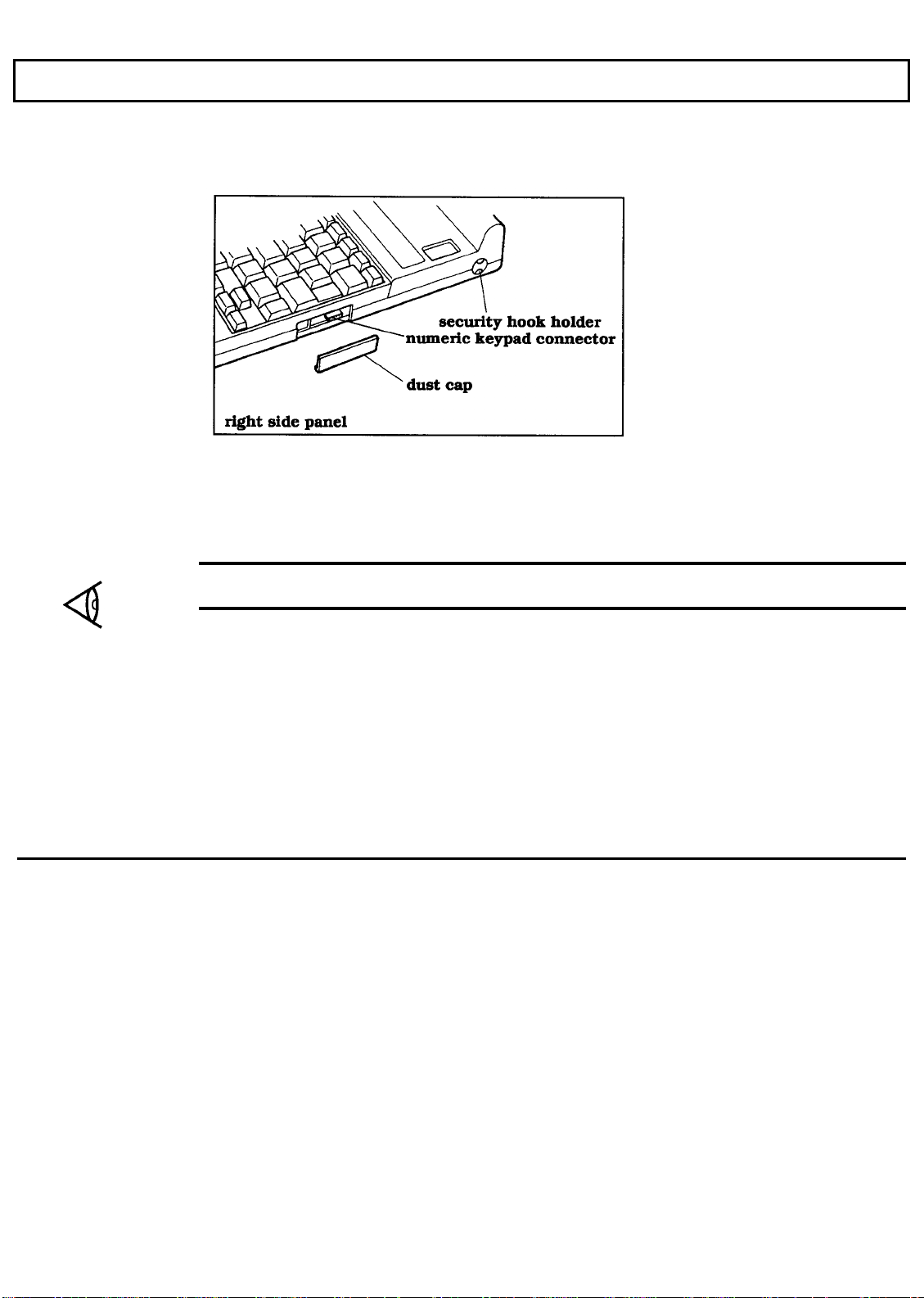
Right Side Panel
The right side panel on the computer contains the numeric keypad connector and the security hook holder, as
shown and described below.
Numeric Keypad Connector
The Numeric Keypad connector connects the optional Numeric Keypad to your computer.
2-6 More About Hardware
Note:
the underside of the Numeric Keypad while the connector is in use.
A dust cap is provided for the Numeric Keypad connector. Remove and store this cap in the slot in
Security Hook Holder
The Security Hook Holder attaches to metal fittings to help prevent theft of the computer.
Page 30
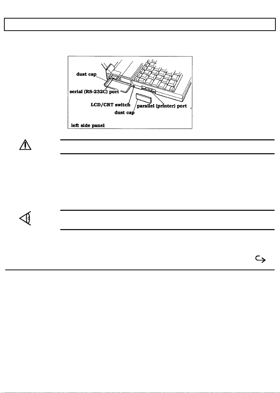
Left Side Panel
There are two connectors and a slide switch on the left side panel of the computer, as illustrated and
described below.
Caution: Connections and settings made on the left side of the computer must be done with the
power off.
Parallel (Printer) Port
You can connect a printer or other device that uses a standard Centronics parallel interface to the TravelMate
2000 via the supplied conversion adaptor. The cable from the printer or other device must terminate in a 25pin IBM-PC-style male connector to connect to this port. Specifications for this connector are given in
Appendix H.
Note:
of the conversion adaptor while the parallel port is in use, and replace the cap when the parallel port is not
in use.
A dust cap is provided for the parallel port. Remove and store this cap in the slot in the underside
More About Hardware 2-7
Page 31

Left Side Panel
LCD/CRT Switch
The TravelMate 2000 can display on either the standard LCD screen or on an external VGA monitor
connected to the optional CRT Adaptor. Set the LCD/CRT switch appropriately. When the switch is set to
CRT with the optional CRT Adaptor installed, the computer LCD screen is off. Always change the switch
setting with the power off. See Chapter 6 for details on the CRT Adaptor and compatible CRTs.
Serial (RS-232C) Port
The RS-232C serial port is located behind a cover on the left side panel. This port connects I/O devices
such as a serial printer, mouse, or an external modem for data communications. The cable that connects to
this port must terminate in a 9-pin female IBM-AT-style connector. For detailed specifications, see
Appendix H.
Caution: The dust cap for the serial port is connected to the unit. Do not try to force this dust cap off.
2-8 More About Hardware
Page 32

Rear Panel
The rear panel of the computer has two connectors and an AC Adaptor jack.
Expansion Bus Connector
The optional Floppy Drive Unit or the optional Expansion Unit plugs into the expansion bus connector on the
rear of the TravelMate 2000. For details, see Chapter 6.
Add-On Battery Pack Connector
The optional Add-On Battery Pack plugs into the Battery pack connector. For details, see Chapter 6.
Note:
caps and store them in the undersides of the options while the connectors are in use, and replace the caps
when the connectors are not in use.
Dust caps are provided for the expansion bus connector and Battery pack connector. Remove the
More About Hardware 2-9
Page 33

Rear Panel
2-10 More About Hardware
AC Adaptor Jack
The AC Adaptor plugs into this jack for recharging the battery or supplying ac power to the computer. See
Chapter 3 for instructions on how to recharge the battery.
Caution: Use only the supplied AC Adaptor with your TravelMate 2000 Computer. Other adaptors
may not match the power requirements of the TravelMate 2000 and can cause serious damage to the
system.
Page 34

Bottom Panel
Battery Slot
The bottom panel of the computer has a slot for the supplied internal battery. For battery installation
instructions, see Chapter 3.
More About Hardware 2-11
Page 35

Front Panel
The front panel of the computer has a power switch, an optional card slot cover, a keyboard, and eight
indicators.
Power Switch
The power switch turns the power to the computer on and off for both battery-powered and ac operation. Set
the switch to the I position to turn on the computer and to the position to turn off the computer.
2-12 More About Hardware
Optional Card Slot Cover
A cover for the optional card slot is located on the rear left of the front panel. The optional CRT Adaptor or
Internal Modem Card can be installed in this slot. For details, see Chapter 6.
Page 36

Keyboard
The TravelMate 2000 keyboard provides all the functions of the IBM enhanced keyboard. Many of the keys
on the keyboard are similar to those on a standard typewriter. There are some keys, however, that might not
be familiar to you. The following is a description of keys not found on a standard typewriter.
Note:
to your software and MS-DOS manuals.
MS-DOS and certain applications use keys for special purposes which are not defined here. Refer
More About Hardware 2-13
Page 37

Keyboard
Enter Key
There are two identical
The
Caps Lock
2-14 More About Hardware
key makes all the alphabet letters you type uppercase. It is a toggle key; pressing it once turns it on and pressing it
The
Return key.
key is generally used to end a line or menu entry and move to the next one; also referred to as the
Enter
Shift
keys. Any alphanumeric key pressed while the
Shift
character or the symbol on the top of the keytop. When the
reverse for alphabetic characters, giving a lowercase letter.
Shift
Caps Lock
again turns it off. When the
Caps Lock
key is on, the
Caps Lock
key is held down gives that key's uppercase
Caps Lock
indicator is lit.
key is on, the
Shift
keys work in
Page 38

Tab
Keyboard
The
you to backtab.
Backspace (
The ←
the cursor.
key works like the tab key on a regular typewriter. Pressing the
Tab
←← )
(Backspace)
key moves the cursor to the left one space at a time, erasing the character to the left of
Shift
key with the
Tab
Ctrl
There are two identical
are pressed at the same time. For example, under MS-DOS, pressing the
sends a
Break
to stop the current program execution.
Ctrl
(Control) keys. The
Ctrl
key changes the function of another key when the two
Pause
key while holding down
Alt
Like the
Ctrl
key, the two identical
Alt
(Alternate) keys give an alternate function to another key.
Alt Gr
On European keyboards, the
is used to enter the characters printed on the lower right of keytops. On other keyboards, a second
located in this position.
Alt Gr
(Alternate Graphics) key is located to the right of the
Spacebar.
key allows
Ctrl
The key
Alt
key is
Fn
Fn
The
keys. See Appendix G for keyboard layouts using the
(Function) key is used to access numbers, characters, or functions printed in blue on the front of the
Fn
key.
More About Hardware 2-15
Page 39

Keyboard
Cursor Control Keys
The four arrow keys move the cursor by spaces or lines in
Fn
The
control functions may vary according to the software application. Refer to your software application manual
for use of these keys. See Appendix G for keyboard layout variations when the
key shifts the functions of these keys to
Home, End, PgUp,
the direction of the keytop arrows.
PgDn.
and
These cursor and screen
Fn
key is used.
Esc
Esc
The
BatteryPro and Productivity Software User’s Manual
(Escape) key is frequently used in applications to cancel a command or exit the application. See the
for the use of this key.
Function Keys
There are ten function keys,
F1 I
keys,
editing functions in MS-DOS (see your MS-DOS manual) and have application-defined functions at other
times. Refer to your application software manual to see which functions are assigned to these keys.
Note:
There is a blank template directly above the function keys where you can label the function of each key
for your applications on the supplied template strips.
and
F12,
are available by pressing the
F1
through
F10,
in the row above the typewriter keys. Two additional function
F1
and
F2
keys with the
Fn
key. The function keys perform
Ins (insert)
2-16 More About Hardware
Ins
The
mode, every character you type appears after the cursor position, moving the existing characters one space to
the right instead of typing over them.
(Insert) key is used to toggle the insert mode on and off in MS-DOS and many applications. In insert
Page 40

Del (Delete)
Keyboard
The
applications, remaining characters usually move left to fill the space.
(Delete) key is used to delete the character at the cursor position. In MS-DOS and many
Del
Num Lk
The
Num Lk
Num Lock
become active, giving a numeric keypad layout. See the Appendix D for details on keyboard layouts.
key
(Fn - Ins)
indicator is lit. When toggled on, the numbers in blue on the front faces of certain typewriter keys
toggles the numeric keypad keys on and off. When the
Num Lk
key is on, the
Scr Lk
Pressing the
has no fixed function of its own, but has special functions in some application programs. Refer to your
application software manual for specific use of this key. When this key is on, the
Fn
and
keys together gives you the
Del
Scr Lk
(Scroll Lock) key. This key
Scroll Lock
indicator is lit.
Pause
The
key temporarily stops the display from scrolling until another key is pressed on the keyboard.
Pause
Break
Pressing the
to stop current program execution.
key while holding down the
Pause
key gives you the
Ctrl
key, which sends a break signal
Break
Sys Rq
The function of the
application. Check your application software for details.
Sys Rq
(System Request) key is not fixed and varies according to the software
More About Hardware 2-17
Page 41

Keyboard
Prt Sc
2-18 More About Hardware
Pressing the
displayed on the screen when a printer is connected. Note that the MS-DOS utility GRAPHICS.COM must
first be executed in order to print graphic displays: otherwise, only text characters will be printed. When
used with the
MS-DOS keyboard functions in your MSDOS manual.
Fn
Ctrl
and
key, the
Sys Rq
keys together gives you the
key prints line by line as you press the
Prt Sc
Prt Sc
(Print Screen) key. This prints whatever is
key. See the description of
Enter
Set Up
The
Set Up
See Chapter 4 for details on the Set Up screen. Pressing the
changes palettes in the RPAL utility. See the BatteryPro and Productivity Software User’s Manual for
Fn)
details.
key displays the screen at which you set default values for the basic operation of the computer.
Set Up
key and the
key together
Fn
(Set Up -
Page 42

Status Indicators
There are eight status indicators on the upper left of the keyboard which light to show the state of the battery,
keyboard and drives.
Power
The
mode.
indicator lights green when the power is on, and lights orange when the computer is in the standby
Power
Low Battery
With the battery in the normally charged state, the
than roughly 90 percent discharged, the indicator turns red. An alarm then beeps for about 15 seconds. If this
occurs, plug in the AC Adaptor immediately. If you continue using the computer without plugging in the AC
Adaptor, the indicator begins to blink and the alarm beeps again. After approximately 30 seconds of blinking
and beeping, the computer is automatically turned off and the contents of memory are lost.
Low Batt
indicator remains off. When the battery is more
Charge
With the computer turned off, the
illuminates when the battery is at least 90 percent charged.
Charge
indicator blinks while the internal battery is being charged, and
Floppy Disk
The
Floppy Disk
indicator comes on when the optional 3.5 inch Floppy Drive Unit is being accessed.
More About Hardware 2-19
Page 43

Status Indicators
Hard Disk
More About Hardware
2-20
The
Hard Disk
Caps Lock
The
Caps Lock
Num Lock
The
Num Lock
lock function.
Scroll Lock
The
Scroll Lock
function.
indicator comes on when the computer writes to or reads from the built-in hard disk.
indicator comes on when you press the
indicator comes on when you press the
indicator comes on when you press the
Caps Lock
Num Lk
Scr Lk
key to toggle on the caps lock function.
key
(Fn - Ins)
key
(Fn - Del)
to toggle the numeric keypad
to toggle on the scroll lock
Page 44

Setting Up
This chapter tells you about:
Operating and storage environments for your Travel-Mate 2000
Installing, removing, and charging the battery
Setting the DIP switches
Contents
Guidelines & Precautions..........................................................................................................3-2
Operating Environment ...............................................................................................3-2
Operating Guidelines..................................................................................................3-2
Installing the Battery ................................................................................................................3-3
Removing the Battery3-5
Charging the Battery/AC Operation...........................................................................................3-7
Setting DIP Switches ................................................................................................................3-9
3
Setting Up
3-1
Page 45

Guidelines & Precautions
Use your TravelMate 2000 according to the following environmental specifications and operating
guidelines.
Operating Environment
When using your computer, always try to ensure that the temperature and humidity of the surroundings fall
within the following ranges.
Temperature
Operating: 10° C to 35° C (50° F to 95° F)
Storage: 20° C to 60° C (-4° F to 140° F)
Relative Humidity (Noncondensing)
Operating: 20 to 80%
Storage: 10 to 90%
Operating Guidelines
Use a standard ac outlet when operating the computer with the AC Adaptor. Make sure the outlet supplies the
correct voltage for your TravelMate 2000.
3-2
For information on how to install hardware options, see Chapter 6 of this manual and the instruction sheet
supplied with the option.
Setting Up
Page 46

Installing the Battery]
Follow these steps to install the battery. Charging the battery is described later.
Turn the computer off and disconnect the AC Adaptor.
1.
2.
3.
Carefully turn the computer over on a padded surface. Then remove the battery cover by sliding it
to the left.
Plug the connector from the battery into the connector inside the case.
Setting Up
3-3
Page 47

Installing the Battery
3-4 Setting Up
Note:
4.
5.
When installing the battery, be careful to keep the lead wires out from under the battery.
Set the battery into the case.
Replace the battery cover by aligning the tabs on the cover with the slots on the computer,
then slide the cover to the right.
Page 48

Removing the Battery
To remove the battery (when installing an internal option, for example):
1.
2.
Turn off the computer and disconnect any external devices.
Position the computer with the bottom panel facing up and remove the battery cover by
sliding it to the left.
Setting Up
3-5
Page 49

Removing the Battery
3.
4.
5.
Covering the battery slot with your hands, turn the computer over and take out the battery.
Disconnect the battery connector.
Replace the battery cover by aligning the tabs on the cover with the slots on the computer,
then slide the cover to the right.
3-6 Setting Up
Page 50

Charging the Battery/AC Operation
The AC Adaptor supplied with your TravelMate 2000 can be used to charge both the internal battery and the
optional Add-On Battery Pack, as well as to operate the computer on ac power,
Caution: Use only the AC Adaptor supplied with your TravelMate 2000. Using another
adaptor can damage your computer. Be sure to plug the AC Adaptor into a grounded outlet or use a
grounded plug adaptor.
It takes about 2 hours to fully recharge the internal battery with the power to the computer turned off. The
Add-On Battery Pack takes about 3.5 hours to recharge. The batteries are also being slowly charged while
you operate the computer on ac power.
A fully charged internal battery allows the computer to run for up to 2 hours. The Add-On Battery Pack
provides approximately 3 hours of operation and the add-on battery/internal battery combination can provide
up to 5 hours of operation.
NiCad batteries tend to lose capacity if they are never fully discharged. An unconditioned battery-one that is
brandnew, one installed in a computer that has not been used for a long time, or one that has sat uninstalled
for a long time must be conditioned before it will achieve maximum life. Otherwise, your battery will hold a
shorter charge than it is capable of holding.
To condition and charge the battery, follow these steps.
1.
2.
Install the internal battery if it is not already installed in your computer.
Allow the battery to fully discharge by using the computer on battery power.
Setting Up
3-7
Page 51

Charging the Battery/AC Operation
3.
After the battery is completely discharged, recharge the battery completely using the AC
Adaptor.
a.
b.
c.
Plug the female end of the supplied ac cord into the inlet on the AC Adaptor body.
Plug the male end of the ac cord into a grounded outlet. Use a grounded plug
adaptor if necessary.
Plug the cord from the AC Adaptor into the jack on the rear panel of the computer.
3-8 Setting Up
The
Charge
the battery is 90 percent charged. The battery takes about 2 hours to completely charge.
4.
5.
indicator on the front of the computer blinks while the battery is charging, then illuminates when
Allow the battery to fully discharge again using the computer normally on battery power.
Recharge the battery completely a second time. Your battery is now conditioned and able
to achieve maximum life.
Page 52

Setting DIP Switches
Two DIP switches are provided inside the computer. These switches allow you to control whether an alarm
sounds when certain conditions are met.
Turn off the computer and disconnect the AC Adaptor if installed.
1.
2.
3.
4.
Locate the option card slot cover on the top left of the computer.
Remove the template strip on the top of the keyboard; this reveals a groove. Hook a flat-
headed object in the groove and open the option card slot cover.
You will find the DIP switches inside the slot. If any option card is installed in the slot,
remove the card to reveal the DIP switches, and store the card in a static free or protected
bag.
Setting Up 3-9
Page 53

Setting DIP Switches
5.
Switch 1 System Speaker
ON On
OFF Off
Switch 2 Low Battery Alarm
ON On
OFF Off
Note:
Set these two DIP switches appropriately using a pointed object such as a ball-point pen.
The DIP switches are used to control the following functions:
Screen Closed Alarm/
Change the DIP switch settings only when the power is off.
3-10 Setting Up
Page 54

This chapter tells you about:
Starting up your TravelMate 2000
Defining your set-up options
Setting up your LCD
Configuring your hardware
Contents
System Start-up.................................................................................................................4-4
Restoring Your System Configuration........................................................................4-5
Laptop Manager Screen.............................................................................................4-6
Accessing the Set Up Screen.............................................................................................4-7
Accessing the Set Up Screen from MS-DOS .............................................................4-7
Accessing the Set Up Screen Directly........................................................................4-7
Making Selections on the Set Up Screen...........................................................................4-8
Set Up Screen Fields.......................................................................................................4-10
Clock .......................................................................................................................4-10
Time .................................................................................................................4-10
Date..................................................................................................................4-10
Display ....................................................................................................................4-10
Cursor Type......................................................................................................4-10
LCD Mode........................................................................................................4-10
Keyboard.................................................................................................................4-11
Caps Lock.........................................................................................................4-11
Num Lock .........................................................................................................4-11
Scroll Lock.......................................................................................................4-11
Repeat Rate ......................................................................................................4-11
Power Saving...........................................................................................................4-11
Display Timeout...............................................................................................4-12
HDD Motor Off................................................................................................4-12
4
Getting Started
Getting Started 4-1
Page 55

Contents
System Timeout........................................................................................................4-12
System Configurations.....................................................................................................4-13
CPU Speed/Bus Speed.............................................................................................4-13
Quick Boot...............................................................................................................4-13
Standby Key.............................................................................................................4-13
Speed Key................................................................................................................4-13
Serial I/O........................................................................................................................4-14
Baud Rate ................................................................................................................4-14
Data Bits..................................................................................................................4-14
Stop Bits..................................................................................................................4-14
Parity .......................................................................................................................4-14
Setting Up the LCD .........................................................................................................4-15
LCD/CRT Switch ....................................................................................................4-15
Screen Modes..........................................................................................................4-16
Text Mode ........................................................................................................4-17
Graphics Mode.................................................................................................4-17
LCD Modes .............................................................................................................4-17
Setting the Display Mode.........................................................................................4-17
Changing the LCD Color Palette..............................................................................4-18
Displaying the Hardware
Installation Screen ...................................................................................................4-19
Power-On Message ..........................................................................................4-19
Key Operation ..................................................................................................4-19
DIAG Command...............................................................................................4-19
Making Selections on the Hardware
Installation Screen ...................................................................................................4-21
Hardware Installation Screen Fields .......................................................................4-22
Display Configuration.......................................................................................4-22
Display Mode............................................................................................4-22
Display Adaptor........................................................................................4-22
I/O Configuration..............................................................................................4-22
Internal and Optional Serial Ports.............................................................4-22
Internal Parallel Port................................................................................................4-23
ROM Disk Port........................................................................................................4-23
EMS I/O Port...........................................................................................................4-23
Drive Assignments...................................................................................................4-23
Drive A/Drive B...............................................................................................4-23
4-2 Getting Started
Page 56

Drive C/Drive D .......................................................................................4-24
Memory Configuration......................................................................................4-24
Internal Memory Size ................................................................................4-24
Boundary Address.....................................................................................4-24
Restarting the System...............................................................................................4-26
Backing Up the Hard Disk .......................................................................................4-27
Contents
Getting Started 4-3
Page 57

System Start-up
The TravelMate 2000 computer comes from the factory with software already installed on the hard disk. The
TravelMate 2000 computer contains MS-DOS, version 4.01, LapLink, Laptop Manager, Laptop File
Manager, BatteryPro, Battery Watch,
computer more powerful and easier to use.
When starting the computer, follow these steps.
. If you have not done so, set up your computer for either battery operation or AC Adaptor
1
RPAL
palette utility, and other software programs that make your
operation, as described in Chapter 3.
2. Turn
The TravelMate 2000 then loads the expanded memory driver, BatteryPro, MS-DOS, Cache, Shadow, RPAL,
Battery Watch, and Laptop Manager, displaying messages on the screen as each program loads.
the power on. The TravelMate 2000 begins its internal memory check and displays
this screen:
Then displays this screen:
4-4 Getting Started
Page 58

System Start-up
3.
If you have not removed the internal battery or installed an internal option, the computer
displays the Laptop Manager screen.
Restoring Your System Configuration
The system configuration in your Texas Instruments TravelMate 2000 Notebook Computer can be lost if you
do any of the following:
Remove the internal battery
Discharge the battery completely without immediately recharging it
Allow your computer to sit idle without charging the battery for more than 10 days
If you lose your system configuration, follow this procedure when starting your computer.
1. . Charge the internal battery as described in Chapter 3. Ensure that your wall outlet provides
the voltage required for your computer.
2. After the battery is fully charged, turn on the computer by setting the power switch to the I
(on) position. The computer displays the following message:
Press Enter to run the Hardware Installation
Press F1 to continue
3. Press the Enter key.
4. If any additional error messages appear, press any key to acknowledge and continue.
5. When the Hardware Installation screen appears, press and hold the Crtl key and press the
Spacebar to install the factory default values.
Getting Started 4-5
Page 59

System Start-up
6.
7.
The computer again restarts, and the Laptop Manager main menu reappears.
Press the
and restart the computer.
When the Laptop Manager main menu appears, press the
resetting the factory default values.
key and then press the
SetUp
key to exit the Hardware Installation screen
Enter
(Reset Config) key to complete
F8
Laptop Manager Screen
After MS-DOS has been loaded, along with the configured software, the standard Laptop Manager screen
appears as in the following example.
4-6 Getting Started
Read the BatteryPro and Productivity Software User’s Manual for the instructions to use Laptop Manager.
Page 60

Accessing the Set Up Screen
You can customize many of the settings of your system so that your TravelMate 2000 always powers up with
those settings. Normally, you should access the Set Up screen when the MS-DOS prompt is displayed,
although you can access the Set Up screen from an application program.
Accessing the Set Up Screen from MS-DOS
You can enter the Set Up screen when the MS-DOS prompt is displayed by pressing the
Pressing the
screen. If you access the Set Up screen from the MS-DOS prompt, the computer does not reboot when you
exit the Set Up screen.
Set-Up
key executes the SET-UP command in the \DOS directory, which displays the Set Up
Set Up
key.
Accessing the Set Up Screen Directly
You can access the Set Up screen directly from any program by holding down the
pressing the
Set Up screen, which clears memory.
Set Up
Caution: You should avoid pressing the Ctrl-Alt-Set Up keys when you are in an
application program. The computer restart when it exits the Set Up screen, which erases the
contents of memory.
key. When you access the Set Up screen this way the computer reboots upon leaving the
Ctrl
and
Alt
keys and
Getting Started 4-7
Page 61

Making Selections on the Set Up Screen
4-8 Getting Started
1.
2.
To move forward through each field, use the → key (Right Arrow) or the ↓ key (Down
Arrow). To move backward through each field, use the ← key (Left Arrow) or the ↑ key
(Up Arrow).
To move to the first field in the next category, press the
to the first field in the previous category, press the
To move to the very first category, press the
press the
After moving to a field, press the
field. Select the desired setting and move to the next field.
End
key.
Spacebar
PgUp
key. To move to the very last category,
Home
to cycle through the possible settings for the
key (Page Down). To move
PgDn
key (Page Up).
Page 62

Making Selections on the Set Up Screen]
3.
4.
Note:
you exit the Set Up screen.
The selections you make on the Set Up screen are backed up by the battery. AR selections are maintained
even when power is turned off. If the battery is removed for approximately 5 minutes (when installing an
internal option, for example), or if the battery is discharged, some of the selections may be invalid. When
this happens, hold the
Each field on the Set Up screen is described on the following pages.
Press the
prompts you to press the
Press the
discard the new settings and return to MS-DOS or press the Set Up key to return to the Set
Up Screen.
If you entered the Set Up screen by pressing the
Set Up
Enter
key or the
key to save the new settings and return to MS-DOS. Press the
key down and press the
Ctrl
key when you have finished all entries. Then the system
Esc
Enter, Esc,
or
Set Up
keys.
Ctrl-Alt-Set Up
Spacebar
keys, the system restarts when
to install valid default values in all fields.
Esc
key to
Getting Started 4-9
Page 63

Set Up Screen Fields
Clock
The computer contains a battery-operated clock that keeps track of the time and date. This category allows
the current time and date to be set and modified.
Time
This field specifies the current time. Time is set either in a 12-hour or a 24-hour clock format depending on
the country setting. To advance the time, press the
key. For the 12-hour clock format, press the
seconds to 00.
Date
This field specifies the current date. The date is set either in the month-day-year or the day-month-year order
depending on the country setting. The day of the week (MON, TUE, WED, etc.) is set automatically as the
date is entered.
Display
This category sets the shape of the screen cursor and vertically expands the display on the LCD in certain
modes.
Spacebar
Spacebar
or use the + key. To set the time back use the -
to change between
Am
and PM. This also resets the
4-10 Getting Started
Cursor Type
The shape of the cursor can be changed to one of the following settings: Underline, Underbar, or Block.
LCD Mode
The standard LCD screen has a resolution of 640 dots horizontally by 480 dots vertically. In MDA, CGA
and EGA display modes, however, the screen does not normally use all of the 480-dot vertical display area.
Specifying expanded mode for these display modes expands the screen display vertically to use the full
screen. Possible settings are Standard or Expanded.
Page 64

Set Up Screen Fields
To use the entire display, set the LCD mode to Expanded. However, for some CGA- and EGA-based
applications where the aspect ratio is critical, it may be desirable to use the Standard setting.
Keyboard
This category specifies the state of the three lock keys and the key repeat rate when the system is started up.
Caps Lock
Specifies the default state of the
Caps Lock
key. Possible settings are On or Off.
Num Lock
Specifies the default state of the
Num Lk
key. Possible settings are On or Off.
Scroll Lock
Specifies the default state of the
Scr Lk
key. Possible settings are On or Off.
Repeat Rate
Specifies the default key repeat rate. Possible settings are Fast or Standard.
Power Saving
This category specifies the period of three power-saving functions. Each power-saving function occurs
approximately within the specified period.
Note:
running application programs. Read the BatteryPro and Productivity Software User’s Manual for more
information on optimizing battery charge life.
Your TravelMate 2000 is configured with BatteryPro, which helps you conserve battery life while
Getting Started 4-11
Page 65

Set Up Screen Fields
Display Timeout
After a certain period of inactivity, with no input from the keyboard, the system automatically shuts off the
power to the LCD screen. Pressing any key on the keyboard turns the LCD back on. The length of the timeout
period can be set or the LCD can be kept on continuously. Possible settings are Always On, I minute, 2
minutes, 5 minutes, or 10 minutes. This feature is also valid for an external monitor.
Note:
time when the computer turns on power to the disk motor before accessing the disk. See the BatteryPro and Productivity
4-12 Getting Started
Note:
If you use a mouse in an application, you might want to set the Display Timeout to Always On.
HDD Motor Off
In order to conserve battery life, the hard disk motor can be set to turn off automatically after a period with no
accesses to the hard disk. Possible settings are Always On, 15 seconds, 30 seconds, 1 minute, 2 minutes, 5
minutes, or 10 minutes.
Although turning off the hard disk when not in use conserves battery life, you can experience a slowing of disk access
Software Users Manual for Information.
System Timeout
After a certain period with no input from the keyboard, the system automatically enters the standby mode.
The hard disk drive is turned off and the
Ctrl-Alt-Pause
can be set or the computer can be kept on continuously. The possible settings are Always On, 1 minute, 2
minutes, 5 minutes, or 10 minutes.
keys on the keyboard returns the system to the active mode. The length of the timeout period
indicator turns orange. Pressing the
Power
FN-Pause
key or the
Page 66

Set Up Screen Fields
System Configurations
This category specifies various settings concerning the system configuration.
CPU Speed/Bus Speed
These fields specify the CPU clock speed and bus clock speed used on power-up. The speeds are set as a
pair and change simultaneously to the values displayed when you exit the Set Up screen. The possible
settings are 12 MHz/6 MHz, 6 MHz/6 MHz, or 7.16 MHz/7.16 MHz.
Quick Boot
This field selects quick loading of the system. When this field is set to On, the system bypasses some of the
power-on self checks (including memory check) when starting up. The possible settings are On or Off.
Standby Key
This field lets you enter standby mode using the keyboard. Normally, the system enters the standby mode
after a specified period of inactivity. If this field is set to Enable, the system enters standby mode when the
Fn-Pause
keys or
Ctrl-Alt-Pause
keys are pressed. The possible settings are Enable or Disable.
Speed Key
This field lets you change the CPU clock speed from the keyboard. If you set this field to Enable, you can
change the CPU clock speed using the
computer. Pressing the
order, and pressing the
6MHz order. The possible settings are Enable or Disable.
Ctrl-Alt-↑↑
Ctrl-Alt-↓↓
Ctrl-Alt-↑↑
keys quickens the CPU speed step by step in the 6MHz-7.16MHz-12MHz
keys slows down the CPU speed step by step in the 12MHz-7.16 MHz-
keys or the
Ctrl-Alt-↓↓
keys on the keyboard while using the
Getting Started 4-13
Page 67

Set Up Screen Fields
You can hear a high-pitched beep when pressing the
the
Ctrl-Alt-↓↓
the lower CPU speed.
Note:
DIP switches.
You can display the current CPU speed by using the Speed Utility. See the BatteryPro and Productivity
Software User’s Manual for more information.
Note:
not be effective even when Enable is set on the Set Up screen. In this case, use the system timeout function
or change the CPU speed on the set up screen.
keys. The higher beep results from the higher CPU speed, while the lower beep results from
DIP switch I must be on in order to hear the beeps. See Chapter 3 for information on how to set the
In some cases, the above key functions (
Ctrl-Alt-↑↑
Fn-Pause, Ctrl-Alt-Pause, Ctrl-Alt-
keys and a lower pitched beep when pressing
↑↑ or
Ctrl-Alt-
↓↓) may
Serial I/O
This category defines the communications settings for the standard and optional serial input/output (SIO)
ports.
Baud Rate
Possible settings are 110, 150, 300, 600, 1200, 2400, 4800, or 9600.
4-14 Getting Started
Data Bits
Possible settings are 7 or 8.
Stop Bits
Possible settings are 1 or 2.
Parity
Possible settings are None, Odd, or Even.
Page 68

Setting Up the LCD
The TravelMate 2000 computer gives you many ways to set up the LCD, which allows you to create the
screen configuration that suits your needs best. This section provides an overview of your options while
setting up the LCD. The sections on the Set Up screen and Hardware Installation screen provide detailed
information about your options.
When setting up the LCD on your computer, you should keep the following information in mind.
Refer to your application program manual for instructions on how to set the display mode
on the Hardware Installation screen, described later in this chapter. Then choose Standard
or Expanded LCD mode on the Set Up screen. The default setting is Standard. In general,
Standard mode gives a more accurate display of graphics, but may not fill the LCD screen
in some display modes. Expanded mode will fill the screen, but may "stretch" some
graphics unacceptably.
Your computer automatically selects the display mode (text or graphics) required by your
application software when the Display Mode field is set to VGA Mode and the Display
Adaptor field on the Hardware Installation screen is set to Internal VGA.
You can use the Shadow and RPAL utilities that come with the TravelMate 2000 to
increase the readability of the cursor and LCD display for most application programs.
Refer to the BatteryPro and Productivity Software User’s Manual for details of these
programs.
LCD/CRT Switch
Your TravelMate 2000 contains a VGA display adaptor. This display adaptor can be used with either the
internal LCD screen or an external VGA monitor when an optional CRT Adaptor is installed.
Getting Started 4-15
Page 69

Setting Up the LCD
The LCD/CRT switch (on the left side panel) determines whether the image is displayed on the LCD or on an
optional external VGA monitor.
When the LCD/CRT switch is set to CRT, the internal VGA display adaptor sends display
When the LCD/CRT switch is set to LCD, the internal VGA display adaptor uses the built-
signals to an external monitor connected to the optional CRT Adaptor. The CRT Adaptor
supports the following external monitors:
- Multi-frequency monitors
- 31 kHz/70 Hz (400/200 line mode), 60 Hz (480 line mode) IBM PS/2 (VGA) monitors
in LCD display, emulating 16 colors as 16 shades of gray. To assign colors to shades of
gray, a palette utility, called RPAL, is supplied. This utility is described in the BatteryPro
and Productivity Software User’s Manual.
4-16 Getting Started
Note:
The computer must be rebooted for changes made in the palette utility to take effect.
A detailed description of screen standards is included in Appendix J.
Screen Modes
The internal display adaptor in the TravelMate 2000 supports IBM screen standards (CGA, MDA, EGA,
VGA) both for the LCD screen and for compatible external monitors, and emulates the Hercules Graphics
Card (HGC) only for external multi-frequency monitors. An application program may not support all of these
standards. Check your application program manual to determine which display modes are supported. The
CGA, EGA, VGA and HGC standards have both text and graphics modes. The MDA standard does not
support graphics displays.
Page 70

Setting Up the LCD
Text Mode
In text mode, text is displayed on a 25-line screen in either 40 or 80 columns in CGA, EGA and VGA modes.
Graphics Mode
The TravelMate 2000 LCD screen can display high-quality graphic images. The VGA mode gives the best
results, since it has the highest screen resolution. If your application does not support VGA, then EGA is an
alternate high-resolution display mode. CGA is available for applications that do not support the higher
resolution modes.
LCD Modes
The TravelMate 2000 has two LCD modes-standard and expanded-which are selected by accessing the Set
Up screen, as described earlier in this chapter. In standard mode, the display area for CGA, MDA and EGA
does not fill the LCD screen, so there are borders at the top and bottom of the screen. In expanded mode, the
displays are expanded vertically-by duplicating a line every few lines-to use as much of the 640 by 480
screen as possible.
Setting the Display Mode
The MS-DOS
on an external monitor. For the LCD type the command:
Refer to the
Note:
MODE
command allows you to specify the text display mode on the TravelMate 2000 LCD or
MODE
40 - for 40 chars/line or
MODE
80 - for 80 chars/line.
MODE
command in your MS-DOS manual for a detailed description.
The 40-column text display is not supported in the MDA and HGC modes.
Getting Started 4-17
Page 71

Setting Up the LCD
Changing the LCD Color Palette
The TravelMate 2000 LCD screen displays up to a maximum. of 16 colors as shades of gray. The shade of
gray selected to represent each of the 16 colors can be changed by the user to maximize contrast between
adjacent gray scale shades when running programs which use particular color combinations. A given
mapping of gray scales to colors is called a palette. See the RPAL section of the BatteryPro and
Productivity Software User’s Manual for more information.
4-18 Getting Started
Page 72

Displaying the Hardware
Installation Screen
If you have removed the battery or added an internal option, you may need to configure the hardware on the
Hardware Installation screen. You can display the Hardware Installation screen in the following three ways:
Power-On Message
When turning on the computer or after adding an option, you may see the following message on the screen:
Invalid Configuration Information
-Press Enter to run the hardware installation.
-Press F1 to continue.
This message indicates that the settings on the Hardware installation screen do not match the actual hardware
configuration you are using. Press the
F1 key will bypass the message and allow you to start MS-DOS, although you still will have to set the new
hardware configuration later.
Key Operation
key to display the Hardware Installation screen. Pressing the
Enter
Access the Set Up screen (described earlier in this chapter) either by pressing the
down the
keys on the Set Up screen displays the Hardware Installation Screen.
Up
Ctrl
and
keys or by pressing the
Alt
Set Up
key at the MS-DOS prompt. Pressing the
Set Up
key while holding
Ctrl-Alt-Set
DIAG Command
DIAG
Type
displays an opening menu. Select the Hardware Installation item from this menu. See Appendix E for a
description of the diagnostics program.
at the MS-DOS prompt and press the
key. The diagnostic program automatically runs and
Enter
Getting Started 4-19
full
Page 73

Displaying the Hardware
Installation Screen
The Hardware Installation screen with its default settings appears as follows:
4-20 Getting Started
Page 74

Making Selections on the Hardware
Installation Screen
1.
2.
3.
4.
The selections you make on the Hardware Installation screen are backed up by the battery. All selections are
maintained even when the power is turned off. If the battery is removed for more than approximately 5
minutes (when installing an internal option, for example), or if the battery is discharged, the selections may
be invalid. When using the computer for the first time after the battery was removed or after the computer has
not been used for a long period, reset the appropriate values in the Hardware Installation screen to their
default values by pressing the
To move forward through each field, use the → key (Right Arrow) or the ↓ key (Down
Arrow). To move backward through each field, use the ← key (Left Arrow) or the ↑ key
(Up Arrow).
To move to the first field in the next category, press the
to the first field in the previous category, press the
To move to the very first category, press the
press the
After moving to a field, press the
field. Stop at the desired setting and move to the next field.
Press the
press the
Press the
settings and return to MS-DOS. The system will restart in either case.
key.
End
Spacebar
Set Up
Enter, Esc,
Enter
key when you have finished all entries. Then the system prompts you to
or
Set Up
key to save the new settings or press the
Ctrl-Spacebar
key.
keys.
PgUp
key. To move to the very last category,
Home
to cycle through the possible settings for the
key (Page Down). To move
PgDn
key (Page Up).
key to discard the new
Esc
Each field on the Hardware Installation Screen is described on the following pages.
Getting Started 4-21
Page 75

Hardware installation Screen Fields
Display Configuration
There are two settings for the display.
Display Mode
The Display Mode specifies the mode of the internal VGA controller. The possible settings are: VGA Mode,
EGA Mode, CGA mode, MDA mode, and HGC mode. The HGC mode is effective only for an external CRT
monitor connected through the optional CRT Adaptor.
Display Adaptor
The Display Adaptor specifies whether the internal VGA controller or an external display adaptor card
installed in the optional Expansion Unit is being used. This field is effective only when the optional
Expansion Unit is attached to the computer. Otherwise, the internal VGA controller is used regardless of the
setting in this field. The possible settings are Internal VGA, CGA-40 col, CGA-80 col, and MDA.
I/O Configuration
This category specifies the configuration of various I/O ports.
4-22 Getting Started
Internal and Optional Serial Ports
These fields select the port numbers for the standard internal serial port and the optional internal serial port,
usually used for an internal modem. You can assign either port as Port 1 or Port 2, but you cannot assign the
same port number to both ports. You can also Disable either or both ports. To assign port values, press the
Spacebar
until the screen displays the desired configuration.
Page 76

Hardware Installation Screen Fields
Internal Parallel Port
This field assigns a number to the standard parallel port. Possible settings are Port 1, Port 2, and Disable.
ROM Disk Port
This field specifies the ROM disk I/O port address. The possible settings are from 108h- 10Bh to 1F8h1FBh.
EMS I/O Port
This field specifies the EMS device driver I/O port address (EMM4J.SYS). The possible settings are 208h20Bh to 2E8h-2EBh.
Note:
port addresses. The addresses apply even when the ROM disk or the EMS device driver is not used.
Make sure the addresses for the ROM disk port and EMS I/O port do not conflict with other I/O
Drive Assignments
Drive A/Drive B
If a 3.5-inch Floppy Drive Unit is connected to the computer, the drive is assigned drive letter A regardless
of the settings in this field. Although a 5.25-inch floppy drive is not an option of the TravelMate 2000, a
third-party 5.25-inch floppy drive connected to the port on the 3.5-inch Floppy Drive Unit is always
designated Drive B.
Getting Started 4-23
Page 77

Hardware
installation Screen Fields
Drive C/Drive D
These fields specify the drive assignments of the internal hard disk and the ROM disk. You should usually
assign Drive C to the Internal HDD and Drive D to none. If you need to boot from the ROM disk to restore
the system, you should assign Drive C to the ROM disk and Drive D to the internal HDD. See Appendix K
for instructions on restoring MS-DOS to the hard disk.
Memory Configuration
This category specifies the configuration of the internal memory.
Internal Memory Size
This field specifies the total amount of internal memory. The amount of memory on the expansion card(s)
installed in the Expansion Unit is not included in this size. Possible settings are 1M byte, 2M bytes, or 3M
bytes.
Boundary Address
This field specifies the boundary address between internal Extended memory and Extended memory in the
Expansion Unit.
4-24 Getting Started
Using the above two values, the system calculates the following four sizes:
Main Memory-
Extended Memory-
Expanded Memory-
minimum is 128 K bytes.
This field always shows 640 K bytes.
This field shows the amount of internal Extended memory.
This field shows the amount of internal Expanded memory. The
Page 78

Hardware Installation Screen Fields
See Appendix H for the relationship between the settings in this category and each memory size.
Disabled Memory-
user.
This field shows the amount of memory which is not available to the
Getting Started 4-25
Page 79

Restarting the System
You may sometimes want to return the system to its start-up state-with only MS-DOS, CONFIG.SYS and
AUTOEXEC.BAT in memory-without turning off the power. This is called restarting or "rebooting" the
system (sometimes called a "warm boot," as opposed to a "cold boot," which includes turning the power off
and on again).
Caution: Any information in main memory will be lost when you restart the computer. Be sure
to save any files you are working on first before rebooting.
4-26 Getting Started
To perform a warm boot, press the
as if power was just turned on-it performs an internal check, then loads MS-DOS from the hard disk. The
initial memory check is bypassed.
key while holding down the
Del
Ctrl
and
keys. The system responds
Alt
Page 80

Backing Up the Hard Disk
Although the hard disk is a precision device, the data stored in it may be lost due to shock or vibration of the
disk or in the event of disk or hardware failure. Once lost, the data cannot be restored unless you have
backup copies. Be sure to back up the contents of the hard disk from time to time onto another computer using
the COPY command in the LapLink utility or, if you have an optional floppy drive assembly, onto diskettes
using the BACKUP command. For information on the LapLink utility, see the LapLink manual.
Getting Started 4-27
Page 81

Installing and Using
Application Programs
This chapter tells you about
Guidelines for loading IBM AT-compatible application programs
The furnished LapLink program that transfers files and lets you use another computer's
peripheral devices
How to set up and use the furnished Laptop Manager program for your operating
environment
Contents
Guidelines for Installing Applications.............................................................................. 5-3
Installing Applications Without the
Floppy Drive Option................................................................................................. 5-3
Installing Programs Not Copy-Protected............................................................ 5-4
Installing Copy-Protected Programs................................................................... 5-4
Installing Applications Using the
Floppy Drive Option................................................................................................. 5-5
Installation Considerations........................................................................................ 5-5
Display 5-5
Keyboard ........................................................................................................... 5-5
Communication Ports......................................................................................... 5-6
Processing Speed............................................................................................... 5-6
Memory 5-6
AUTOEXEC.BAT and CONFIG.SYS Files...................................................... 5-7
Default AUTOEXEC.BAT File ......................................................................... 5-7
Default CONFIG.SYS File ................................................................................ 5-9
LapLink ........................................................................................................... 5-10
5
Application Programs 5-1
Page 82

Contents
5-2 Application Programs
LapLink File Transfer Utility .................................................................................. 5-10
LapLink Device Driver........................................................................................... 5-11
Laptop Manager.............................................................................................................. 5-13
Laptop Manager Main Menu ................................................................................... 5-13
Quick Commands Box...................................................................................... 5-14
Single-Character Quick Commands ................................................................. 5-14
Selecting Applications From the
Applications List ...................................................................................... 5-15
Using the Password Utility............................................................................................. 5-16
Accessing the Password Utility............................................................................... 5-16
Installing a Password.............................................................................................. 5-17
Changing a Password.............................................................................................. 5-17
Removing a Password............................................................................................. 5-18
Password Function.................................................................................................. 5-19
Page 83

Guidelines for Installing Applications
Your TravelMate 2000 is fully compatible with IBM AT computers - All application programs written to
execute on AT computers will execute on the TravelMate 2000, and you can install the programs in much the
same way on the TravelMate 2000. However, like most computers, you must consider the exceptions to the
installation process before you install programs into the TravelMate 2000.
Installing Applications Without the
Floppy Drive Option
If your TravelMate 2000 is not equipped with the floppy drive option, you can use the furnished LapLink file
transfer and device driver utility to install or copy a program by using another IBM AT-compatible computer.
Note:
Before copying any commercial software currently in use on another computer, read the License Agreement and
copyright protections that apply to that product. Many agreements limit the use of an application program to
one owner, or even to one CPU-based system. If you are already using the software on an existing system,
you may be prohibited from also running it on another computer. In other cases, you may have to completely
remove the software from the current system before you can use it on another computer. It is your
responsibility to ensure compliance with the terms and conditions pertaining to any software products you
plan to use with the LapLink feature. Texas Instruments assumes no responsibility for the illegal or
unauthorized use of proprietary software products on Texas Instruments TravelMate computers.
Application Programs 5-3
Page 84

Guidelines for Installing Applications
Installing Programs Not Copy-Protected
If the application program you want to install in the TravelMate 2000 is not copy-protected and is already
installed on another AT-compatible computer, you can use LapLink to copy the program to your TravelMate
2000. Refer to the LapLink User's Manual furnished with your TravelMate 2000 for detailed instructions.
5-4 Application Programs
Note:
you must configure the program and/or the TravelMate 2000 to the highest-resolution display that each can
support. See your application software manual for details. Some programs allow you to change the display
configuration while running; others require you to specify monitor type when you initially install the
program,
If the display on the AT-compatible computer with the application program is not a VGA monitor,
Installing Copy-Protected Programs
If the application program you want to install in the TravelMate 2000 is copy-protected or if you can
configure the program only during the installation process, you can use the LapLink device driver feature and
the floppy drive of an AT compatible computer to install the program.
The LapLink device driver program enables the drives on your TravelMate 2000 to work as if they were a
component of the other computer, so you can install the program according to the program's installation
procedure using the floppy drive of the other computer. You can also use this procedure if the application
program is available only on 5.25-inch floppies and your computer does not have a 5.25 inch floppy drive.
Refer to Section 4 of the LapLink User's Manual for detailed instructions on this procedure.
Page 85

Guidelines for Installing Applications
Installing Applications Using the
Floppy Drive Option
If you have the optional floppy drive unit attached to your TravelMate 2000, you can use it to install any
application programs available on 3.5-inch floppies. Review the following special installation
considerations and install the program according to the instructions furnished with the program.
If the program is not available on 3.5-inch floppies, you can use the furnished LapLink program, using the
procedures described under "Installing Applications Without the Floppy Drive Option' earlier in this chapter.
Installation Considerations
The following configuration items will influence how you install application programs into your TravelMate
2000 (or any computer).
Display
The TravelMate 2000 has a 80-column by 25-line display with 640-by-480 (VGA) resolution and four other
lower resolution displays. When installing an application program, select the highest-resolution monitor
configuration for the program and the TravelMate 2000 that both can support.
Keyboard
The TravelMate 2000 keyboard emulates all functions of an IBM AT - 101 enhanced keyboard. When
installing an application program, select the IBM 101 or AT -enhanced keyboard configuration.
Application Programs 5-5
Page 86

Guidelines for Installing Applications
Communication Ports
The serial port is Port 1 (default) and the optional Internal Modem, if installed, is Port 2 (default). When
installing an application program requiring communication support, select Port 1 or Port 2, as appropriate.
You can change these values on the Hardware Installation screen (described in Chapter 4).
Processing Speed
Some application programs do not execute at the high speed (12 MHz) on the computer. Check the program
documentation for the required processing speed and change the speed if necessary in one of the following
ways.
On the Set Up screen
5-6 Application Programs
By pressing
With the Laptop Manager menu configuration process (described in the BatteryPro and
Productivity Software User’s Manual).
If you use the Laptop Manager feature to load your application programs, you do not need to change the
system setup procedure each time you load a different application program that requires a different
processing speed.
Ctrl-Alt-↑↑
or
Ctrl-Alt-↓↓
when the Speed Key is enabled on the Set Up screen
Memory
The standard TravelMate 2000 has 1 M byte of memory 640 K byte system memory plus 384 K byte
extended/expanded memory. You can add 1 or 2 M bytes of additional optional memory to your TravelMate
2000 that can be configured either as extended memory or LIM EMS memory. See Appendix H for details on
memory options for your TravelMate 2000.
Page 87

Guidelines for Installing Applications
Review your application program documentation for its memory requirements and set up the TravelMate
2000 memory to maximize your program's performance.
AUTOEXEC.BAT and CONFIG.SYS Files
If your application program requires additions or changes to the TravelMate 2000
CONFIG.SYS
files-as suggested several times in this and other chapters of this manual-carefully consider the
AUTOEXEC.BAT
and
consequences that may result from changes or deletions to these two files. The factory-furnished (default)
files are listed and described in the following two sections. Please read and understand these two files
before you change them. See the MS-DOS User’s Manual furnished with your TravelMate 2000 for more
details on constructing these files and their significance.
Default AUTOEXEC.BAT File
Each line of the TravelMate 2000 default
following the file listing. Take special note of those fines relating to Laptop Manager and LapLink.
echo off
ver
set comspec=c:\dos\command.com
set path=c:\;c:\utils;c:\dos
set mfile=c:\utils
set lapsys=c:\config.sys
set lapfile=c:\
prompt $P$G
cache 64 /e
shadow
rpal /i
bw
lm
AUTOEXEC.BAT
file and its purpose are defined in the table
Application Programs 5-7
Page 88

Guidelines for Installing Applications
Default AUTOEXEC.BAT File
Line Purpose
1 echo off - prevents the Me from displaying on the screen when invoked
2 ver - displays version number of MS-DOS
3 set comspec=c:\dos\command.corn - tells MS-DOS to get its COMMAND.COM
file from drive C. speeds processing.
4 set path=c:\;c:\utilsc:\dos - defines the directories and order in which to search
for files entered on the command line.
this line as required.
5 set mfile=c:\utils - tells Laptop Manager in which directory to find its data file.
This line is required by LapTop Manager
6 set lapsys=c:\config.sys - tells the LapLink file, DDINSTAL.EXE, to look for the
CONFIG.SYS file in the root directory of drive C.
LapLink device driver.
7 set lapfile=c:\- tells LapLink in which directory to find its configuration file.
line is required by LapLink
8 prompt $P$G - tells MS-DOS to display the current drive and directory
9 cache 64 /e - installs Disk Cache in memory
10 shadow - installs Shadow for cursor enhancement
11 rpal /i - installs RPAL, a color palette control program
12 bw - installs Battery Watch program
13 lm - loads Laptop Manager and displays its main menu
Do not remove this line from the file.
You can add additional directories to
.
This line is required by the
This
.
5-8 Application Programs
Page 89

Default CONFIG.SYS File
Guidelines for Installing Applications
Each line of the TravelMate 2000 default
the file listing. You can add commands required by your application program(s), but
CONFIG.SYS
file and its purpose are defined in the table following
delete the
do not
existing default commands.
FILES=20
BUFFERS=20
SHELL=C:\DOS\COMMAND.COM /P /E:256
DEVICE=C:\UTILS\EMM4J.SYS
DEVICE=C:\UTILS\BATTERY.PRO
DEVICE=C:\DOS\ANSI.SYS
INSTALL=C:\DOS\FASTOPEN.EXE C:=(50,25)
Default CONFIG.SYS File
(Modify but do not delete these command lines)
Line Purpose
1 FILES=20 - tells MS-DOS how many files can be open at any one time
2 BUFFERS=20 - tells MS-DOS how many buffers will be used for file
input/output; you can adjust the value as required by your application program to
maximize processing speed.
3 SHELL--C:\DOS\COMMAND.COM /P /E:256 - provides the path for
COMMAND.COM and sets the environment to 256 bytes
4 DEVICE=C:\UTILS\EMM4J.SYS - installs EMMJ4.SYS, the expanded memory
manager device driver
5 DEVICE=C:\UTILS\BATTERY.PRO - loads the device driver BATTERY.PRO
6 DEVICE=C:\DOS\ANSI.SYS-loads the device driver ANSI.SYS for enhanced
standard input/output
7 INSTALL--C:\DOS\FASTOPEN.EXE C:=(50,25) - installs FASTOPEN, which
decreases the amount of time to open frequently used files and directories
Application Programs 5-9
Page 90

LapLink
The LapLink file transfer and device driver programs, products of Traveling Software Inc., are furnished
with your TravelMate 2000. LapLink makes it practical to use a computer without a floppy drive. LapLink
requires use of a special cable also furnished with your TravelMate 2000.
LapLink fills the need for a fast, convenient, error-free means of transferring files. Connected by the
furnished LapLink cable and running the LapLink program, two computers have complete access to each
other's disk drives-and to all the files on those drives, You can copy files the following ways:
From one hard disk directly to another (without using floppies at all)
From one floppy to another (eliminating the incompatibility between 5.25- and 3.5-inch
floppies)
From a hard disk to floppies
LapLink File Transfer Utility
Though copying is its specialty, LapLink is more than a simple file-transfer program. By offering such
features as file Erase, Rename, and View, LapLink has proved itself a useful tool for managing files and
directories on a single computer.
Just as important as what it does is the way LapLink does it. Whether you are copying, erasing, renaming, or
viewing files, using LapLink is easier than using only MS-DOS commands. LapLink shows you the files and
directories you are working with and the commands that perform the various operations.
5-10 Application Programs
Page 91

LapLink
LapLink displays a split screen: on one side you see the files and directories on one computer and on the
other side the files and directories on the other computer. The split screen not only tells you what is
happening on both computers but also gives you access to both. Instead of moving from one computer to the
other, you simply move the highlight between the two sides or "windows." By moving the highlight within a
window you select the particular files or directories you want to copy, rename, erase, and so on. Then by
activating a command you perform the operation.
LapLink commands like Copy and Erase appear across the bottom of the screen and are available at the press
of a key. When a command has finished, you usually see the results on the screen immediately.
Whether you are working with one computer or two, LapLink simplifies many tasks: the organization of disks
into subdirectories, the copying of files from one disk to another and from one directory to another, and the
backing up of entire disks.
LapLink Device Driver
The LapLink device driver gives your computer access to the disk drives and printers connected to another
computer: it's as though those other disks and printers were actually a part of your TravelMate 2000, or vice
versa.
Though the device driver does give you access to another computer's disks and thus to its files-you are better
served if you use
LAPLINK.EXE to
transfer files between computers.
Application Programs 5-11
Page 92

LapLink
5-12 Application Programs
One of the most common uses of the device driver is sharing a printer. You can create files on your
TravelMate 2000 and, through the device driver, print them on a printer already connected to a second
computer. Note that the connection to the printer is indirect: from your TravelMate 2000 to the second
computer through the LapLink cable, from the second computer to the printer through the printer cable.
Users of the TravelMate 2000 and other laptop computers find the device driver useful for running programs
located on a desktop computer from the keyboard of their TravelMate 2000. The programs may be copyprotected, making it impossible to copy them to the TravelMate 2000 in the first place. Even if you decide to
use the device driver you should not forget
LAPLINK.EXE
itself),
See the LapLink User's Manual furnished with your TravelMate 2000 for complete information and
instructions about using LapLink and the LapLink device driver.
is still the better way to transfer files between computers.
LAPLINK.EXE.
Used in combination with the device driver (or by
Page 93

Laptop Manager
Laptop Manager, furnished with your TravelMate 2000, is an application control program. Laptop Manager
provides two submenus into which you can insert application programs you have installed on the hard disk.
You can then load application programs from one of the submenus with one keystroke, and from the other
submenu using the arrow keys and the
Laptop Manager Main Menu
Loaded in your TravelMate 2000 hard disk at the factory and furnished on the BatteryPro and Productivity
Software 3.5-inch floppy, the Laptop Manager program displays its main menu after the power-up and
copyright messages are displayed when you turn on the computer. The main menu enables you to select
application programs with a few keystrokes. Procedures for adding items to the Applications list and Quick
Commands box are described in the BatteryPro and Productivity Software User’s Manual furnished with
your computer.
Enter
key.
Pressing the
enables you to add, delete, or modify items on the main menu. Procedures for using the Change Menu are
provided in the BatteryPro and Productivity Software User’s Manual.
You can exit Laptop Manager to the current MS-DOS prompt from the Laptop Manager main menu by
pressing the
You can return to the Laptop Manager main menu from the MS-DOS prompt (
LM
and pressing the
key at the Laptop Manager main menu loads the Laptop Manager Change Menu screen. It
F12
key.
Esc
by typing
c:\>)
key.
Enter
Application Programs 5-13
Page 94

Laptop Manager
Quick Commands Box
Application programs you add to the Quick Commands box can be selected by pressing the function key
to
you assign to it. For your convenience the Laptop File Manager, Battery Watch, and LapLink file
F9)
utility transfer program are installed and assigned at the factory to the
However, you can replace them with your own application programs using the Change Menu procedure
explained in the BatteryPro and Productivity Software User’s Manual.
F1, F10,
and
keys, respectively.
F11
Single-Character Quick Commands
At the bottom of the Laptop Manager menu Quick Commands box are two single-character commands:
Press the D key and Laptop Manager displays a prompt at the bottom of the screen at which
you can enter MS-DOS commands of up to 67 characters. Pressing the
command. When the command is executed, pressing any key returns you to the Laptop
Manager main menu.
Press the P key and Laptop Manager displays a prompt at the bottom of the screen at which
you can change drives and/or directories. For example, you can change from the
prompt to the
prompt at the bottom left corner of the menu changes to a
User’s Manual for details on selecting and changing drives and directories.
prompt by typing P and
A:\
and pressing the
A:
key. Note that the
Enter
prompt. See your MS-DOS
A:\
Enter
key starts the
C: \
C:\
(F2
5-14 Application Programs
Page 95

Using the Password Utility
The TravelMate 2000 includes the Password utility, a program which limits access of your computer only to
people who know the password you specify using this utility. The password is valid until you remove or
change it using the Password utility.
In addition, the Laptop Manager provides password protection on a per-application program basis. See the
BatteryPro and Productivity Software User’s Manual for more information about the Password features for
the Laptop Manager.
Accessing the Password Utility
1 . At the
PW
and press the
Note:
The following Password Utility screen appears:
From the Password Utility screen you can install, change or remove a password, or you can exit the
screen.
2.
Make sure
To select an action, move the bar cursor to the desired selection using the ↑ key or the ↓
key (Up or Down Arrow), and press the
prompt, type
C:\>
PATH
Enter
key.
is set to
C: \DOS
.
key.
Enter
Application Programs 5-15
Page 96

Installing a Password
Using
the Password Utility
1.
2.
3.
Note:
type either PASSWORD or Password.
To install a password, select "Install Password" from the Password Utility screen. The
following screen appears:
Type a password of up to eight characters and press the
Press the
action and return to the Password Utility screen.
The Password utility does not distinguish between upper and lower case; for example, you can
If you select "Install Password" when you have already installed a password, the following
message appears:
Password already exists
Pressing any key on the keyboard will return you to the Password Utility screen.
key again to install the new password, or press the
Enter
Enter
key.
key to cancel the
Esc
5-16 Application Programs
Changing a Password
1.
To change the current password, select "Change Password" from the Password Utility
screen. The following screen appears:
Page 97

Using the Password Utility
2.
3.
4.
Type the current password and press the
it is not seen by other people.
If you type the correct password, the message "Password check OK" appears on the next
line and you are prompted to enter the new password.
Type a new password of up to eight characters and press the
Press the
action and return to the Password Utility screen.
If you type the wrong password, the message "Incorrect Password" appears on the next line
and you are prompted to press any key to return to the Password Utility screen. You may
try to change the password again, or exit the Password Utility screen by selecting Exit.
key again to install the new password, or press the
Enter
Removing a Password
1.
To remove the current password, select "Remove Password" from the Password Utility
screen. The following screen appears:
key. Your entry is shown as squares so that
Enter
key.
Enter
key to cancel the
Esc
Application Programs 5-17
Page 98

Using the
Password Utility
2.
Type the current password and press the
it is not seen by other people.
If you type the correct password, the message "Password check OK" appears on
the next line. Press the
key to cancel the action and return to the Password Utility screen.
Esc
If you type the wrong password, the message "Incorrect Password" appears on the
next line and you are prompted to press any key to return to the Password Utility
screen. You may try to remove the password again, or exit the Password Utility
screen by selecting Exit.
key to remove the current password, or press the
Enter
key. Your entry is shown as squares so that
Enter
Password Function
Once you install the password, you will see the following message every time you start up the computer:
Password
Type the correct password in either upper or lower case and press the
password, the screen is cleared and the system begins to load.
If you type the wrong password, the message "Incorrect Password" appears and you are
prompted to enter the password again. You have three chances to enter the correct
password. If you enter the wrong password three times, the system locks and starts
beeping. If this happens, restart the system by pressing the
you have only one chance to enter the correct password before the system locks.
Ctrl-Alt-Del
key. If you type the correct
Enter
keys. This time,
5-18 Application Programs
Page 99

Using the Password Utility
If you enter the correct password after several incorrect passwords, the following message
appears:
Password :
Password OK
incorrect passwords attempts
Press any key to continue
This message shows how many wrong passwords have been entered since you last entered
the correct password. This may indicate that someone has tried to use your computer
without permission.
Once you enter the correct password, you again have three chances to enter the password at
the next system start-up.
If you forget your password, you will not be able to use the computer. Should this happen,
contact your Texas Instruments dealer.
Note:
Store the password in a secure place away from where you store or operate your computer.
We recommend always malting a note of the password you have installed, in case you forget it.
Application Programs 5-19
Page 100

TravelMate 2000 Options
This chapter tells you about:
Options available for your TravelMate 2000
FCC requirements for modem users
Care for your modem
Contents
Add-On Battery Pack........................................................................................................ 6-2
Instal l i n g t h e B a t t e r y P a c k......................................................................................... 6-2
Charging the Battery Pack ......................................................................................... 6-3
Charge Indication............................................................................................... 6-4
Low Battery Indication....................................................................................... 6-4
3.5-inch Floppy Drive Unit .............................................................................................. 6-5
Attaching the Floppy Drive Unit................................................................................ 6-5
3.5-inch Floppies...................................................................................................... 6-6
Formatting a Floppy........................................................................................... 6-7
Taking Care of Floppies .................................................................................... 6-7
Inserting a Floppy into the Drive........................................................................ 6-9
Numeric Keypad ...........................................................................................................6-10
Connection ........................................................................................................... 6-10
RAM Card ........................................................................................................... 6-12
Installing the RAM Card ......................................................................................... 6-12
CRT Adaptor ........................................................................................................... 6-16
Installation ........................................................................................................... 6-16
External Monitor ........................................................................................................... 6-18
2400 BPS Modem with Send-Fax
and MNP Class 5 .................................................................................................... 6-19
80C287 Coprocessor...................................................................................................... 6-20
Installing the 80C287 Coprocessor......................................................................... 6-20
External Keyboards........................................................................................................ 6-24
Printers ........................................................................................................... 6-25
6
TravelMate 2000 Options 6-1
 Loading...