

Page 1

TPS25820 and TPS25821 Evaluation Module
User's Guide
Literature Number: SLVUAZ3A
September 2017–Revised November 2019
Page 2

Contents
1 Introduction......................................................................................................................... 4
2 Schematic........................................................................................................................... 5
3 Test Points.......................................................................................................................... 6
4 Powering Up the EVM........................................................................................................... 7
4.1 Measuring TPS25820 Device Power Consumption ................................................................. 7
5 Enabling and Configuring the TPS25820................................................................................. 8
5.1 Enabling and Disabling the TPS25820................................................................................ 8
5.2 Configuring the Broadcasted Current Limit for the TPS25820 Device............................................ 8
6 TPS25820/21EVM Features.................................................................................................... 9
6.1 No Connection on the EVM .......................................................................................... 10
6.2 Connecting a Source (SRC) Device.................................................................................. 10
6.3 Connecting a Sink (SNK) Device .................................................................................... 10
6.4 Connecting a Full-Featured USB Type-C™ Cable ................................................................ 11
6.5 Legacy Charging Support ............................................................................................. 11
7 TPS25820/21EVM Output Signals LEDs Operation.................................................................. 12
7.1 FAULT Detected (FAULT# LED) ..................................................................................... 12
7.2 Sink (SNK) device attached Detected (UFP# LED)................................................................ 12
7.3 Flipped USB Type-C™ Cable Detected (POL# LED).............................................................. 12
8 TPS25820 EVM Board Layout............................................................................................... 13
9 Bill of Materials .................................................................................................................. 16
10 PCB Layout Recommendations............................................................................................ 17
11 Trademarks ....................................................................................................................... 17
Revision History.......................................................................................................................... 17
2
Table of Contents
Copyright © 2017–2019, Texas Instruments Incorporated
SLVUAZ3A–September 2017–Revised November 2019
Submit Documentation Feedback
Page 3

www.ti.com
1 TPS25820/21EVM........................................................................................................... 4
2 TPS25820 EVM Schematic ................................................................................................ 5
3 Test Points.................................................................................................................... 6
4 Choosing the Right Power Source ........................................................................................ 7
5 Connecting the Ammeter to IN1 Pin and Pre-Selected Power Source ............................................... 8
6 How to Enable and Disable TPS25820 Device on the EVM........................................................... 8
7 Jumper J6 Setting for Each Broadcasted Current Level ............................................................... 9
8 Schematic Showing How CC1 and CC2 are Connected to Jumpers J9 and J10 .................................. 9
9 Simulating a Sink (SNK) Device Connected to TPS25820/21EVM.................................................. 10
10 Connecting a Full-Featured USB Type-C™ Cable to TPS25820/21EVM.......................................... 11
11 Schematic of TPS2514A Device Section ............................................................................... 11
12 Top Silkscreen.............................................................................................................. 13
13 Top Solder Mask ........................................................................................................... 13
14 Top Layer.................................................................................................................... 14
15 Bottom Layer................................................................................................................ 14
16 Top Assembly............................................................................................................... 15
1 Test Points.................................................................................................................... 6
2 TPS25820 Responses Based on Port Connection Type ............................................................. 12
List of Figures
List of Tables
SLVUAZ3A–September 2017–Revised November 2019
Submit Documentation Feedback
Copyright © 2017–2019, Texas Instruments Incorporated
List of Figures
3
Page 4
User's Guide
SLVUAZ3A–September 2017–Revised November 2019
TPS25820 and TPS25821 Evaluation Module
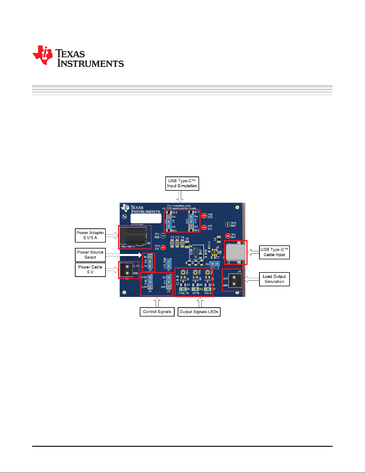
This user’s guide is for the TPS25820 and TPS25821 Evaluation Modules (hereafter referred to as
TPS25820/21EVM) and explains how to get up and running with the TPS25820/21EVM. The EVM allows
the user to test specific features of the TPS25820 device by lighting-up signals LEDs and measuring test
points voltages to demonstrate what happens when different types of USB Type-C™ devices are attached
to the USB Type-C port on the EVM. Note that this EVM does not support BC1.2 charging. A TPS2514A
can be added to DP and DM lines of the USB Type-C connector for BC1.2 charging support. The
TPS25820/21EVM is built with a TPS25820. The TPS25820 has the same functionality of the TPS25821
with the only difference being VCONN. The TPS25821 does not supply VCONN when an electronically
marked cable is connected unlike the TPS25820.
1 Introduction
The TPS25820 device is a simple to use USB Type-C controller with an integrated 1.5-A rated USB VBUS
power switch. The TPS25820 device meets the source requirements as defined in the USB Type-C
specification and implements the source state machine for the detection of USB Type-C device
attach/detach, connection orientation, and attached device type. For more information about the
TPS25820 and TPS25821 devices, see the TPS25820, TPS25821 USB Type-CTM 1.5-A Source
Controller and Power Switch data sheet.
4
TPS25820 and TPS25821 Evaluation Module
Figure 1. TPS25820/21EVM
SLVUAZ3A–September 2017–Revised November 2019
Copyright © 2017–2019, Texas Instruments Incorporated
Submit Documentation Feedback
Page 5
100k
1%
R7
GND
5V/1.5A
CHG
EN
FAULT# UFP# POL#
GND
FAULT#
UFP#
POL#
CC2
CC1
OUT
IN1
Q1
Green
D1
GND
Green
D2
GND
Green
D3
GND
Q2 Q3
5.1k
R11
GND
CC1
5.1k
R13
GND
CC2
GND
TIP (+)
1
2
3
J9
1
2
3
J10
Ra
Rd
Ra
Rd
1
2
3
J6
1
2
3
J3
GND
Dp
Dn
J11
OUT
100k
R1
100k
R2
100k
R3
TP3
TP4
DNP
TP5
DNP
TP6
DNP
TP2
J1
TP7 TP8
1.0k
R14
1.0k
R12
360
R6
360
R5
360
R4
LED_PWR
5V
TP1
GND
J8
REF
GND GND GND GND
Vin Range:
IN: 4.5 - 5.5 V
Source Current : 1.5A
0
R9
0
R10
GND
J_IN
GND
CC1
9
CC2
11
CHG
3
EN
4
GND
10
IN
2
IN
1
OUT
12
PAD
13
REF
8
FAULT
5
POL
7
UFP
6
U1
TPS25820DSS
GND
0.1µF
C5
1
3
2
J5
PJ-202AH
1
2
3
J7
GND
A1
TX1+
A2
TX1-
A3
VBUS
A4
CC1
A5
D+
A6
D-
A7
SBU1
A8
VBUS
A9
RX2-
A10
RX2+
A11
GND
A12
GND
B1
TX2+
B2
TX2-
B3
VBUS
B4
CC2
B5
D+
B6
D-
B7
SBU2
B8
VBUS
B9
RX1-
B10
RX1+
B11
GND
B12
H1
H1
H2
H2
H3
H3
H4
H4
H5
H5
H6
H6
11223
3
J2
20-0000016-01
GND
6.8µF
C6
J4
Vout
GND
Dp
Dp
Dn
Dn
CC2
200
R8
DNP
CC1 GND
OUT
TP9
GND
10µF
C8
GND
GND
DP1
1
GND2NC
3
NC
4
IN
5
DM1
6
U2
TPS2514DBVR
DNP
0.1µF
C1
0.1µF
C7
47µFC247µFC347µF
C4
Copyright © 2017, Texas Instruments Incorporated
www.ti.com
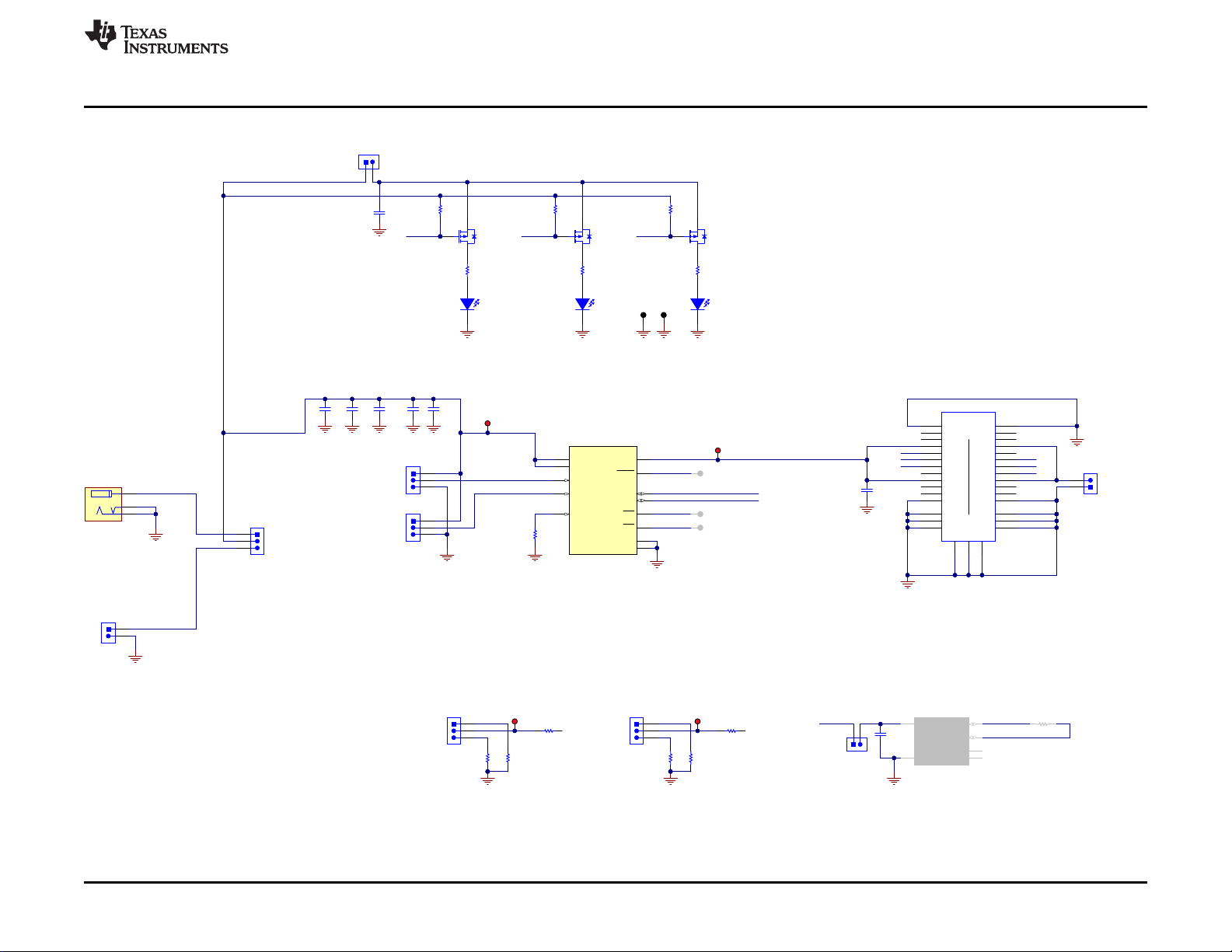
2 Schematic
Schematic
SLVUAZ3A–September 2017–Revised November 2019
Submit Documentation Feedback
Figure 2. TPS25820 EVM Schematic
TPS25820 and TPS25821 Evaluation Module
5
Copyright © 2017–2019, Texas Instruments Incorporated
Page 6
Test Points
3 Test Points
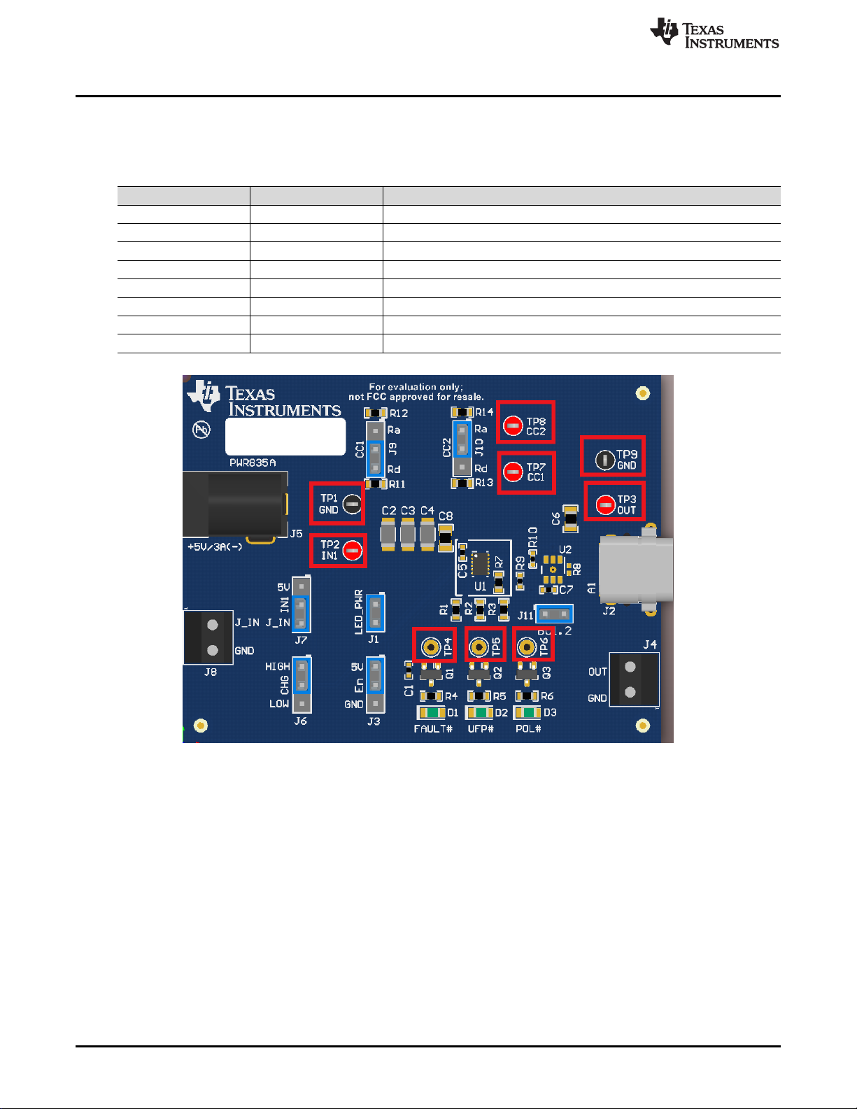
Table 1 lists the test points and the description of each test point.
Test Point Label Description
TP1 GND Ground connecting for input and output signals
TP2 IN1 Input Voltage
TP3 OUT Output Voltage
TP4 FAULT# Active low fault signal
TP5 UFP# Active low Sink (SNK) detect signal
TP6 POL# Active low polarity signal
TP7 CC1 CC1 Voltage
TP8 CC2 CC2 Voltage
www.ti.com
Table 1. Test Points
Figure 3. Test Points
6
TPS25820 and TPS25821 Evaluation Module
Copyright © 2017–2019, Texas Instruments Incorporated
SLVUAZ3A–September 2017–Revised November 2019
Submit Documentation Feedback
Page 7
5-V/3-A Power Adapter
J7
J_IN
IN1
5V
TPS25820
TPS25820
J7
J_IN
IN1
5V
J8
5-V/3-A Power Supply
J_IN
GND
www.ti.com
4 Powering Up the EVM
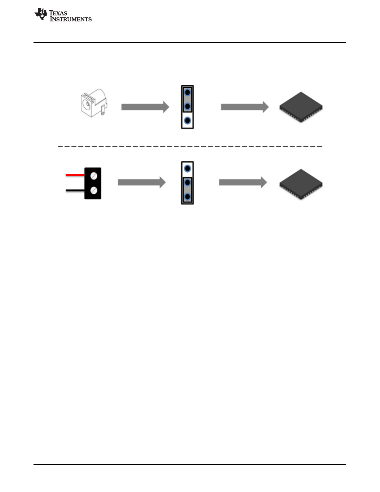
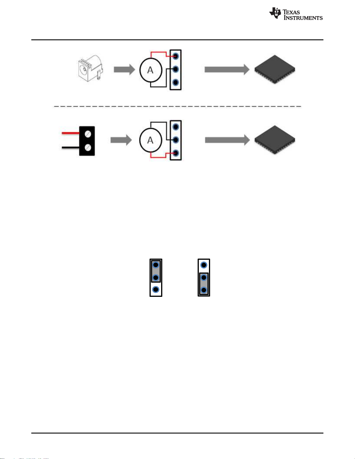
The TPS25820/21EVM has two input-power Sources: a 5-V/3-A barrel jack adapter or a power supply
through J8 connector. These two power Sources provide power to the TPS25820 device IN pin by setting
jumper J7 either to barrel jack or to J1_IN as shown in Figure 4.
Powering Up the EVM
TI recommends a power adaptor that is a standard 2.1-mm DC power adaptor with a positive tip that can
support 5-V and 3-A. An example of a power adaptor to use is the WSU050-3000 wall power supply.
When using a power supply through J8 connector as a power source, make sure to stay within the
specified voltage limits for each pin listed in the data sheet
4.1 Measuring TPS25820 Device Power Consumption
The TPS25820 device is powered through IN pin which is the same pin that powers OUT pin, thus the
easy way to measure power consumption is to connect an ammeter to jumper J7 on the EVM. Figure 5
shows how to connect the Ammeter to IN1 pin through J7 jumper (depending on how the EVM is
powered). For accurate power consumption measurements, remove jumpers J1 and J11 powering output
signals LEDs and BC1.2 device respectively.
When no Sink is attached to the USB port on the EVM, the TPS25820 consumes only 1 μA. To test this,
have the Ammeter connected properly to jumper J7, remove jumper J1 to disconnect output signals LEDs,
jumper J11 to disconnect TPS2514A device, jumpers J9 and J10 to disconnect Rd resistors for CC lines,
and make sure nothing is connected to the USB port.
Figure 4. Choosing the Right Power Source
SLVUAZ3A–September 2017–Revised November 2019
Submit Documentation Feedback
Copyright © 2017–2019, Texas Instruments Incorporated
TPS25820 and TPS25821 Evaluation Module
7
Page 8
5V
EN
Disabled
5V
EN
Enabled
5-V/3-A Power Adapter
J7
J_IN
IN1
5V
TPS25820
TPS25820
J7
J_IN
IN1
5V
J8
5-V/3-A Power Supply
J_IN
GND
J5
Enabling and Configuring the TPS25820
Figure 5. Connecting the Ammeter to IN1 Pin and Pre-Selected Power Source
5 Enabling and Configuring the TPS25820
www.ti.com
5.1 Enabling and Disabling the TPS25820
The TPS25820 has an enable pin that creates a convenient way to turn on or off the device without
interrupting the power Source. Jumper J3 on the TPS25820/21EVM can be used to enable or disable
TPS25820 device, Figure 6 shows enable and disable positions for this jumper.
5.2 Configuring the Broadcasted Current Limit for the TPS25820 Device
TPS25820 device can advertise (using CC lines) how much current it can supply to the attached Sink
device. The two current limits that the TPS25820 device support are: STD and 1.5-A. Jumper J6 allows
switching between these two current limit levels by either setting the jumper to 5-V (High) or to GND (Low)
which in turn sets CHG pin on the TPS25820 device to change the current limit advertisement level.
Figure 7 shows how to set Jumper J6 to advertise the desired current limit broadcast through the CC
lines.
Figure 6. How to Enable and Disable TPS25820 Device on the EVM
8
TPS25820 and TPS25821 Evaluation Module
Copyright © 2017–2019, Texas Instruments Incorporated
SLVUAZ3A–September 2017–Revised November 2019
Submit Documentation Feedback
Page 9

CHG
HIGH
LOW
CHG
Jumper Position
Broadcasted Current Limit
Broadcasted Current Limit: STD
Actual Current Limit: 1.7 A
Broadcasted Current Limit: 1.5 A
Actual Current Limit: 1.7 A
www.ti.com
Figure 7. Jumper J6 Setting for Each Broadcasted Current Level
6 TPS25820/21EVM Features
The TPS25820/21EVM allows for all the features of the TPS25820 device to be tested without a USB
Type-C Cable and external Sink device. This section lists the most common types of situations that can
happen with the TPS25820/21EVM and within each section is an explanation of how to test each situation
with and without external components. Remember how the test jumpers J9 and J10 (which control CC1
and CC2, respectively) connect to the TPS25820 device and the resistors. Figure 8 shows how these
resistors are connected.
TPS25820/21EVM Features
Figure 8. Schematic Showing How CC1 and CC2 are Connected to Jumpers J9 and J10
When connecting a physical USB Type-C Cable into the port of the EVM, make
sure to disconnect jumpers (J9, J10) and disconnect any loads on J4 connector
(which is connected to OUT pin) in order to avoid interference on the CC lines
SLVUAZ3A–September 2017–Revised November 2019
Submit Documentation Feedback
CAUTION
TPS25820 and TPS25821 Evaluation Module
Copyright © 2017–2019, Texas Instruments Incorporated
9
Page 10
J9
J9
Sink with Standard USB Type-&Œ&DEOH&RQQHFWHG Sink with Full Featured USB Type-&Œ&DEOH&RQQHFWHG
Ra
CC1
R
Ra
CC2
R
J9 J10
ON OFF
UFP# POL#
Normal
Cable
Orientation
Ra
CC1
R
Ra
CC2
R
J10 J10
ON OFF
UFP# POL#
Flipped
Cable
Orientation
Ra
CC1
R
Ra
CC2
R
J10
ON OFF
UFP# POL#
Ra
CC1
R
Ra
CC2
R
J10
ON OFF
UFP# POL#
TPS25820/21EVM Features
6.1 No Connection on the EVM
When nothing is connected to the output of the TPS25820/21EVM, the TPS25820 will not output any
power over the OUT pin. In this mode the TPS25820 device will consume only 1 μA.
In order to replicate this mode on the EVM, make sure that jumpers J1, J9, J10, and J11 are left open (not
set to any position) so that power goes only to the TPS25820 device.
6.2 Connecting a Source (SRC) Device
The TPS25820 device is a Source and it continuously monitors the CC lines to detect if an SINK device is
attached. The way it determines if a SINK is attached by monitoring the voltages on CC lines to see if
these voltages get pulled down by an Rd resistors values. Connecting SOURCE device such as the
TPS25820 to another SOURCE device will not turn on the output of the TPS25820 device since both
Sources will continue to monitor their CC lines for a valid connection (Rd pull-down resistors). This can be
tested on the TPS25820/21EVM by connecting a known Source device to the USB Type-C port on the
EVM or by connecting two TPS25820/21EVMs via a USB Type-C cable.
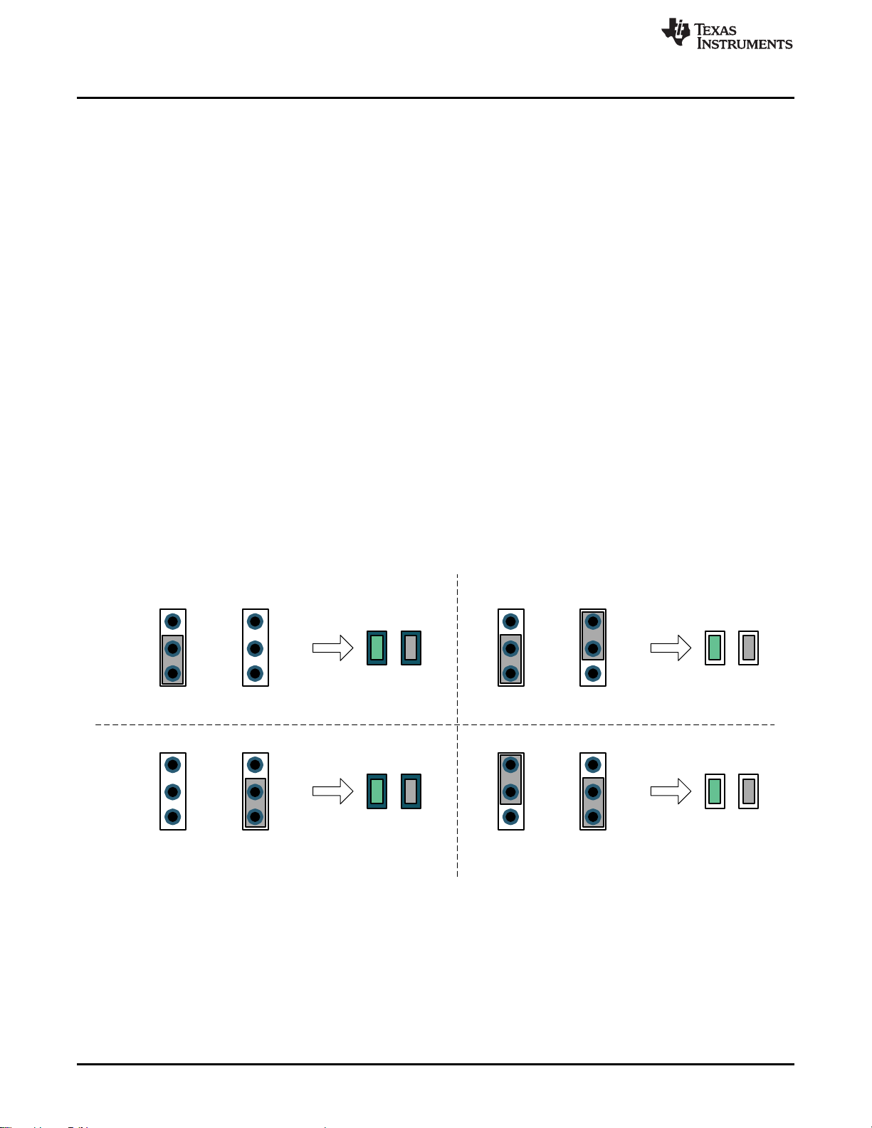
6.3 Connecting a Sink (SNK) Device
A Sink device can be attached to a Source device such as the TPS25820 via a standard USB Type-C
cable or a full-featured USB Type-C cable. The TPS25820 device detects that a Sink is attached by
sensing if any of the CC lines is pulled down by an Rd resistor value. If a Sink with a full-featured USB
Type-C cable is attached, then one CC line will be pulled down by an Rd resistor value while the other CC
line will be pulled down by a Ra resistor value, thus the TPS25820 device will supply VCONN on the CC
line with the Ra resistor value. The TPS25820/21EVM will report the polarity of the Sink device attached to
its USB port via POL# LED when a flipped USB Type-C cable is connected. To replicate those two types
of Sink connections along with their cable polarity orientations on the TPS25820/21EVM, set jumpers J9
(controls CC1) and J10 (controls CC2) based on Figure 9. Figure 9 shows UFP# and POL# signals LEDs
behavior based on jumper J9 and J10 settings.
www.ti.com
10
TPS25820 and TPS25821 Evaluation Module
Figure 9. Simulating a Sink (SNK) Device Connected to TPS25820/21EVM
Copyright © 2017–2019, Texas Instruments Incorporated
SLVUAZ3A–September 2017–Revised November 2019
Submit Documentation Feedback
Page 11

Ra
Rd
CC1
J9
Ra
Rd
CC2
J10
UFP#
POL#
ON
OFF
Ra
Rd
CC1
Ra
R
CC2
UFP#
POL#
ON
OFF
www.ti.com
6.4 Connecting a Full-Featured USB Type-C™ Cable
The way the TPS25820 device detects a Sink device is attached is by checking if either of the CC lines is
connected to Rd resistor value, connecting only a full-featured USB Type-C cable to the port on the EVM
will not light-up UFP# and POL# LEDs since TPS25820 Sink attached signal will not be triggered. To
replicate such connection on the TPS25820 EVM, set jumpers J9 or J10 to apply Ra resistor value to CC
line as shown in Figure 10. Note that the UFP# and POL# LEDs will not light up.
Figure 10. Connecting a Full-Featured USB Type-C™ Cable to TPS25820/21EVM
TPS25820/21EVM Features
6.5 Legacy Charging Support
The TPS25820/21EVM supports legacy USB charging scheme via TPS2514A device which supports
legacy battery charging schemes such as BC1.2. For more information about the TPS2514A device, refer
to the TPS2514A data sheet. Note that in order to connect legacy USB device to the TPS25820/21EVM, a
USB Type-C cable adaptor will be needed. Jumper J11 is used to enable or disable the TPS2514A
device. Figure 11 shows the schematic connection for the TPS2514A device. Note that the TPS2514A is
not populated on the TPS25820/21EVM and would need to be in order to support USB charging schemes.
Figure 11. Schematic of TPS2514A Device Section
SLVUAZ3A–September 2017–Revised November 2019
Submit Documentation Feedback
Copyright © 2017–2019, Texas Instruments Incorporated
TPS25820 and TPS25821 Evaluation Module
11
Page 12

TPS25820/21EVM Output Signals LEDs Operation
7 TPS25820/21EVM Output Signals LEDs Operation
7.1 FAULT Detected (FAULT# LED)
There are two conditions that can cause this fault signal to occur and lights up FAULT# LED; those
conditions are:
1. The output of the TPS25820 exceeds the actual current limit.
2. The TPS25820 device exceeds the Rising threshold temperature for device shutdown or Rising
threshold temperature for OUT/VCONN switches shutdown in current limit.
As soon as the current and the temperature go back to their normal ranges, the fault signal is cleared,
FAULT# LED will turn off, and the device resumes normal operation. Refer to Electrical Characteristics
section located in the TPS25820 data sheet, for more information on the current and temperature
thresholds.
7.2 Sink (SNK) device attached Detected (UFP# LED)
UFP# LED will turn on as soon as a Sink device is attached to the USB Type-C port and is communicating
properly through the CC lines. See Table 2 to determine the necessary conditions for the CC lines to
activate this signal.
Table 2. TPS25820 Responses Based on Port Connection Type
TPS25820 USB Type-C™ Port CC1 CC2 OUT
Nothing Attached OPEN OPEN OPEN NO HI-Z HI-Z
SINK Attached Rd OPEN IN1 NO HI-Z LOW
SINK Attached OPEN Rd IN1 NO LOW LOW
Powered Cable/NO SINK
Attached
Powered Cable/NO SINK
Attached
Powered Cable/SINK Attached Rd Ra IN1 CC2 HI-Z LOW
Powered Cable/SINK Attached Ra Rd IN1 CC1 LOW LOW
OPEN Ra OPEN NO HI-Z HI-Z
Ra OPEN OPEN NO HI-Z HI-Z
www.ti.com
TPS25820 Responses
VCONN on CC1 or CC2 POL# UFP#
7.3 Flipped USB Type-C™ Cable Detected (POL# LED)
Polarity signal was introduced in USB Type-C plug connection since you can insert USB Type-C cable in
either orientation. The TPS25820 device detects the orientation of the USB Type-C Cable attached by
lighting up POL# LED when a Sink device with Flipped USB Type-C Cable is attached. Refer to Table 2 to
see what conditions for the CC lines are necessary to activate this signal.
12
TPS25820 and TPS25821 Evaluation Module
Copyright © 2017–2019, Texas Instruments Incorporated
SLVUAZ3A–September 2017–Revised November 2019
Submit Documentation Feedback
Page 13

www.ti.com
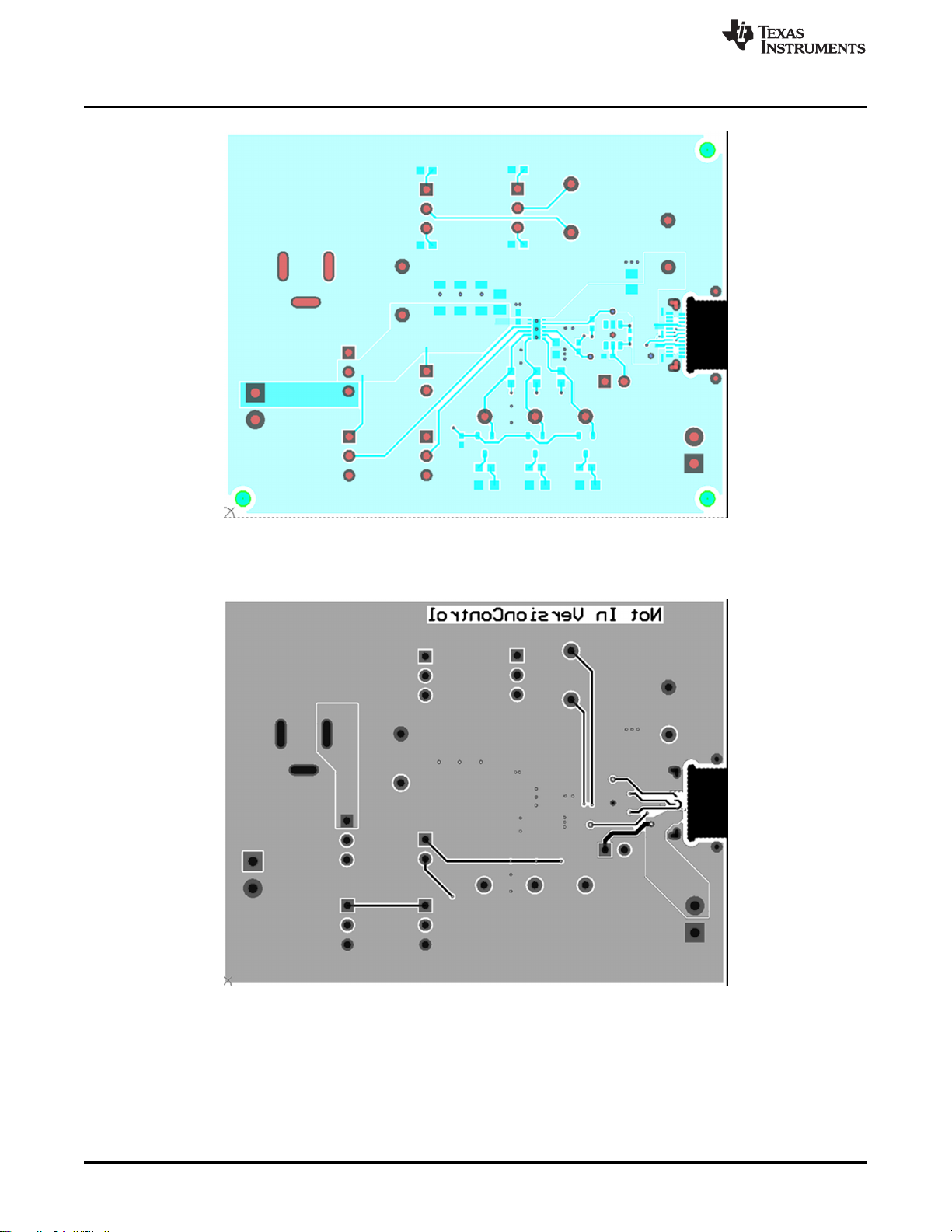
8 TPS25820 EVM Board Layout
The following images show the silkscreen, top, bottom, and assembly layers of the TPS25820/21EVM-xxx
TPS25820 EVM Board Layout
Space
Space
Figure 12. Top Silkscreen
Figure 13. Top Solder Mask
SLVUAZ3A–September 2017–Revised November 2019
Submit Documentation Feedback
Copyright © 2017–2019, Texas Instruments Incorporated
TPS25820 and TPS25821 Evaluation Module
13
Page 14
TPS25820 EVM Board Layout
www.ti.com
Figure 14. Top Layer
Space
Figure 15. Bottom Layer
14
TPS25820 and TPS25821 Evaluation Module
Copyright © 2017–2019, Texas Instruments Incorporated
SLVUAZ3A–September 2017–Revised November 2019
Submit Documentation Feedback
Page 15

www.ti.com
TPS25820 EVM Board Layout
Figure 16. Top Assembly
SLVUAZ3A–September 2017–Revised November 2019
Submit Documentation Feedback
Copyright © 2017–2019, Texas Instruments Incorporated
TPS25820 and TPS25821 Evaluation Module
15
Page 16

Bill of Materials
9 Bill of Materials
Designator Quantity Value Description Package Reference Part Number Manufacturer
C2, C3, C4 3 47uF CAP, CERM, 47 µF, 10 V, +/- 10%, X5R, 1206 1206 GRM31CR61A476KE15L Murata
C6 1 6.8uF CAP, CERM, 6.8 µF, 25 V, +/- 10%, X5R, 0805 0805 C2012X5R1E685K125AC TDK
C8 1 10uF CAP, CERM, 10 µF, 16 V, +/- 20%, X5R, 0805 0805 0805YD106MAT2 AVX
D1, D2, D3 3 Green LED, Green, SMD LED_0805 LTST-C170KGKT Lite-On
J1, J11 2 Header, 100mil, 2x1, Tin, TH Header, 2x1, 100mil, TH 5-146278-2 TEConnectivity
J2 1 Connector, Receptacle, USB Type-C, R/A, SMT
J3, J6, J7, J9, J10 5 Header, 100mil, 3x1, Tin, TH Header, 3x1, 100mil, TH 5-146278-3 TE Connectivity
J4, J8 2 Terminal Block, 6A, 3.5mm Pitch, 2-Pos, TH 7.0x8.2x6.5mm ED555/2DS On-Shore Technology
J5 1 Connector, DC Jack 2.1X5.5 mm, TH Conn,DC Jack, pin 2mm Dia. PJ-202AH CUI Inc.
LBL1 1
Q1, Q2, Q3 3 -50V MOSFET, P-CH, -50 V, -0.13 A, SOT-23 SOT-23 BSS84-7-F Diodes Inc.
R1, R2, R3 3 100k RES, 100 k, 5%, 0.1 W, 0603 0603 CRCW0603100KJNEA Vishay-Dale
R4, R5, R6 3 360 RES, 360, 5%, 0.1 W, 0603 0603 CRCW0603360RJNEA Vishay-Dale
R7 1 100k RES, 100 k, 1%, 0.1 W, 0603 0603 CRCW0603100KFKEA Vishay-Dale
R9, R10 2 0 RES, 0, 5%, 0.063 W, 0402 0402 CRCW04020000Z0ED Vishay-Dale
R11, R13 2 5.1k RES, 5.1 k, 5%, 0.1 W, 0603 0603 CRCW06035K10JNEA Vishay-Dale
R12, R14 2 1.0k RES, 1.0 k, 5%, 0.1 W, 0603 0603 CRCW06031K00JNEA Vishay-Dale
SH-J1, SH-J3, SH-
J6, SH-J7, SH-J9,
SH-J10, SH-J11
TP1, TP9 2 Black Test Point, Miniature, Black, TH Black Miniature Testpoint 5001 Keystone
TP2, TP3, TP7, TP8 4 Red Test Point, Miniature, Red, TH Red Miniature Testpoint 5000 Keystone
U1 1 USB Type-C 1.5 A DFP Controller and Power Switch, DSS0012B DSS0012B TPS25820DSS Texas Instruments
U2 1 USB Dedicated Charging Port Controller, DBV0006A (SOT-23-6) DBV0006A TPS2514DBV Texas Instruments
FID1, FID2, FID3 0 Fiducial mark. There is nothing to buy or mount. Fiducial N/A N/A
R8 0 200 RES, 200, 1%, 0.063 W, 0402 0402 CRCW0402200RFKED Vishay-Dale
TP4, TP5, TP6 0 Red Test Point, Miniature, Red, TH Red Miniature Testpoint 5000 Keystone
7 Shunt, 2.54 mm Gold Blue Shunt, 2.54 mm Blue 60900213621 Wurth Elektronik
Thermal Transfer Printable Labels, 0.650" W x 0.200" H - 10,000 per
roll
Connector, Receptacle, USB
Type-C, SMT
PCB Label 0.650" H x 0.200" W THT-14+423-10 Brady
20-0000016-01 Lintes Technology
www.ti.com
16
TPS25820 and TPS25821 Evaluation Module
SLVUAZ3A–September 2017–Revised November 2019
Submit Documentation Feedback
Copyright © 2017–2019, Texas Instruments Incorporated
Page 17

www.ti.com
PCB Layout Recommendations
10 PCB Layout Recommendations
• Keep input capacitors as close as possible to IC.
• USB protocol recommends having an input capacitance of 120 μF.
• Pullup resistors recommended being 100 kΩ.
• Keep CC lines close to the same length.
• Have the IN and OUT traces as short as possible and wide enough for 1.5-A (3-A if using two
TPS25820.
• The resistor attached to the REF pin and GND pin of the device has two requirements:
– The connection between the resistor and the GND pin should be isolated from the GND plane.
– Place the resistor as close as possible to REF pin.
11 Trademarks
USB Type-C is a trademark of USB Implementer's Forum.
All other trademarks are the property of their respective owners.
Revision History
NOTE: Page numbers for previous revisions may differ from page numbers in the current version.
Changes from Original (September 2017) to A Revision ............................................................................................... Page
• Added TPS25821 evaluation module to the user's guide............................................................................ 4
• Changed caption on Figure 8............................................................................................................ 9
• Updated Figure 9......................................................................................................................... 10
SLVUAZ3A–September 2017–Revised November 2019
Submit Documentation Feedback
Copyright © 2017–2019, Texas Instruments Incorporated
Revision History
17
Page 18

IMPORTANT NOTICE AND DISCLAIMER
TI PROVIDES TECHNICAL AND RELIABILITY DATA (INCLUDING DATASHEETS), DESIGN RESOURCES (INCLUDING REFERENCE
DESIGNS), APPLICATION OR OTHER DESIGN ADVICE, WEB TOOLS, SAFETY INFORMATION, AND OTHER RESOURCES “AS IS”
AND WITH ALL FAULTS, AND DISCLAIMS ALL WARRANTIES, EXPRESS AND IMPLIED, INCLUDING WITHOUT LIMITATION ANY
IMPLIED WARRANTIES OF MERCHANTABILITY, FITNESS FOR A PARTICULAR PURPOSE OR NON-INFRINGEMENT OF THIRD
PARTY INTELLECTUAL PROPERTY RIGHTS.
These resources are intended for skilled developers designing with TI products. You are solely responsible for (1) selecting the appropriate
TI products for your application, (2) designing, validating and testing your application, and (3) ensuring your application meets applicable
standards, and any other safety, security, or other requirements. These resources are subject to change without notice. TI grants you
permission to use these resources only for development of an application that uses the TI products described in the resource. Other
reproduction and display of these resources is prohibited. No license is granted to any other TI intellectual property right or to any third
party intellectual property right. TI disclaims responsibility for, and you will fully indemnify TI and its representatives against, any claims,
damages, costs, losses, and liabilities arising out of your use of these resources.
TI’s products are provided subject to TI’s Terms of Sale (www.ti.com/legal/termsofsale.html) or other applicable terms available either on
ti.com or provided in conjunction with such TI products. TI’s provision of these resources does not expand or otherwise alter TI’s applicable
warranties or warranty disclaimers for TI products.
Mailing Address: Texas Instruments, Post Office Box 655303, Dallas, Texas 75265
Copyright © 2019, Texas Instruments Incorporated
 Loading...