

Page 1

User's Guide
SCDU004–March 2013
TCA8424 Evaluation Module
This document is the EVM user guide for the TCA8424. The device is a low-voltage keyboard scanner that
can support up to 128 keys, with open drain outputs that can sink up to 12 mA of current for LEDs. The
TCA8424 is fully HID over I2C™ compliant and is available with a pre-programmed keyboard map.
Contents
1 About this Manual ........................................................................................................... 2
2 Information about Cautions and Warnings .............................................................................. 2
3 FCC Warning ................................................................................................................ 2
4 Items Required for Operation ............................................................................................. 3
5 Introduction .................................................................................................................. 3
6 TCA8424 EVM Design Circuitry, Bill of Materials, and Connection Descriptions .................................. 4
6.1 TCA8424 EVM Schematic ........................................................................................ 4
6.2 Printed-Circuit Board (PCB) Layout ............................................................................. 5
6.3 Bill of Materials ..................................................................................................... 9
6.4 VCC and GND Connections .................................................................................... 11
6.5 MSP430 Launchpad Interface .................................................................................. 11
6.6 Breakout Pins ..................................................................................................... 12
6.7 LED Outputs ...................................................................................................... 13
7 Launchpad Software Setup .............................................................................................. 14
8 GUI Software Setup ....................................................................................................... 16
9 GUI Walkthrough Guide .................................................................................................. 17
10 Related Documentation ................................................................................................... 30
1 TCA8424 EVM Schematic................................................................................................. 4
2 Layer 1 Top Side: 50-Ω Signal Layer .................................................................................... 5
3 Layer 2 (Int1): Ground Plane.............................................................................................. 6
4 Layer 3 (Int2): 50-Ω Signal with Ground Fill............................................................................. 7
5 Layer 4 Bottom Layer ...................................................................................................... 8
6 VCC and GND Connections ............................................................................................. 11
7 MSP430 Launchpad Interface ........................................................................................... 11
8 Breakout Pins .............................................................................................................. 12
9 LED Outputs ............................................................................................................... 13
1 Bill of Materials.............................................................................................................. 9
2 Header Configurations for P1, P2, and P7............................................................................. 12
SCDU004–March 2013 TCA8424 Evaluation Module
Submit Documentation Feedback
List of Figures
List of Tables
1
Copyright © 2013, Texas Instruments Incorporated
Page 2

About this Manual
1 About this Manual
This user’s guide describes the TCA8424 Evaluation Module (EVM). This guide contains the EVM
schematics, bill of materials, and top and bottom board layouts.
2 Information about Cautions and Warnings
This section describes the jumpers and connectors on the EVM as well and how to properly connect, set
up, and use the TPS22985EVM.
This EVM contains components that can potentially be damaged by
electrostatic discharge. Always transport and store the EVM in its supplied ESD
bag, when not in use. Handle using an antistatic wristband. Operate on an
antistatic work surface. For more information on proper handling, see the
Electrostatic Discharge (ESD) application note (SSYA008).
www.ti.com
CAUTION
The information in a caution or a warning is provided for your protection. Please read each caution and
warning carefully.
3 FCC Warning
This equipment is intended for use in a laboratory test environment only. It generates, uses, and can
radiate radio frequency energy and has not been tested for compliance with the limits of computing
devices pursuant to subpart J of part 15 of FCC rules, which are designed to provide reasonable
protection against radio frequency communications, in which case the user, at their own expense is
required to take whatever measures necessary to correct this interference.
2
TCA8424 Evaluation Module SCDU004–March 2013
Copyright © 2013, Texas Instruments Incorporated
Submit Documentation Feedback
Page 3

www.ti.com
4 Items Required for Operation
The following items are required to program a TCA8424:
• TCA8424 EVM with un-programmed TCA8424 in socket
• Single 3.3-V supply
• MSP-EXP430G2 Rev 1.5 Launchpad with MSP430G2553 installed
• USB to mini-USB cable
• PC with Code Composer Studio installed running supplied firmware
• PC with Application GUI installed
The following items are required to evaluate at the system level:
• TCA8424 EVM with programmed TCA8424 in socket
• Breakout wires to connect to keyboard matrix rows and columns
• Keyboard matrix
• Host system with I2C plus INT connected to board
5 Introduction
The benefits of the TCA8424 over other microcontroller-based solutions are lower development costs,
smaller package, and lower power consumption. The lower development costs are seen due to the
TCA8424 requiring programming of only 512 Bytes of OTP versus a full code stack on a microcontroller.
The TCA8424 is fully compliant with HID over I2C based systems with little to no host firmware
development.
The TCA8424 can also be used in a non-Hid over I2C environment by developing host drivers that mimic
the HID over I2C protocol to interpret the input reports. The EVM features a socket to allow easy
programming of multiple units for testing. The code stack supplied with the EVM is designed to interface
with the MSP430G2553 Launchpad to accomplish this. Once programmed, the EVM features breakout
headers for the keyboard and I2C connections to test in customer systems.
Items Required for Operation
SCDU004–March 2013 TCA8424 Evaluation Module
Submit Documentation Feedback
3
Copyright © 2013, Texas Instruments Incorporated
Page 4

TCA8424 EVM Design Circuitry, Bill of Materials, and Connection Descriptions
6 TCA8424 EVM Design Circuitry, Bill of Materials, and Connection Descriptions
6.1 TCA8424 EVM Schematic
Figure 1 shows the schematic for the EVM. The connections on the EVM are briefly explained in the
subsequent sections.
www.ti.com
4
TCA8424 Evaluation Module SCDU004–March 2013
Figure 1. TCA8424 EVM Schematic
Copyright © 2013, Texas Instruments Incorporated
Submit Documentation Feedback
Page 5
www.ti.com
TCA8424 EVM Design Circuitry, Bill of Materials, and Connection Descriptions
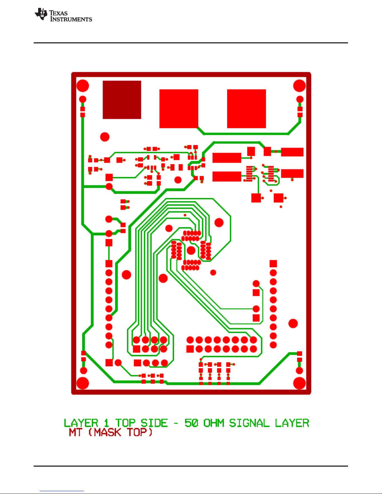
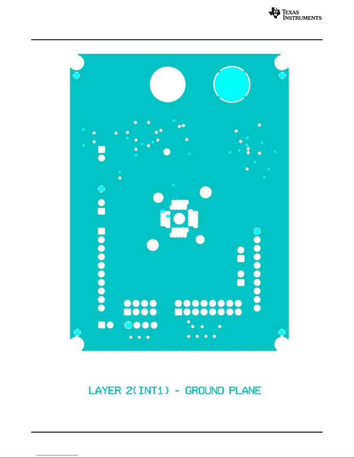
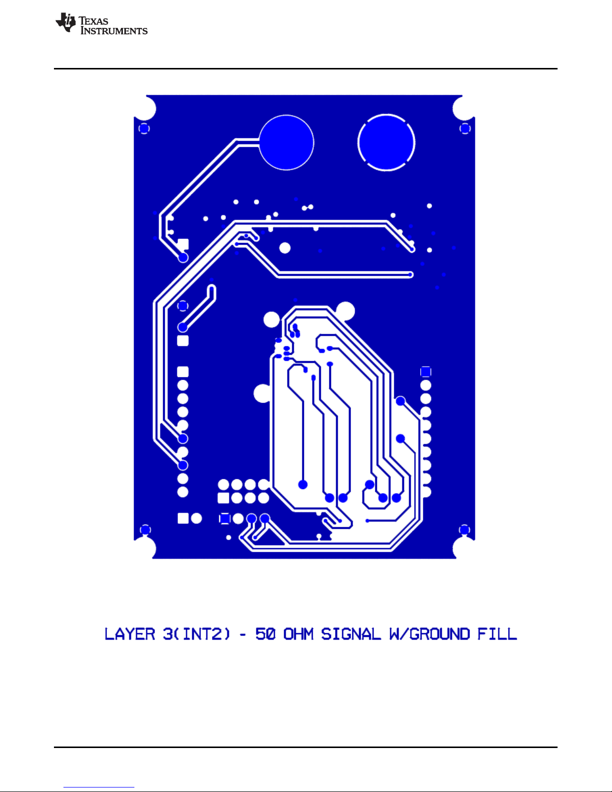
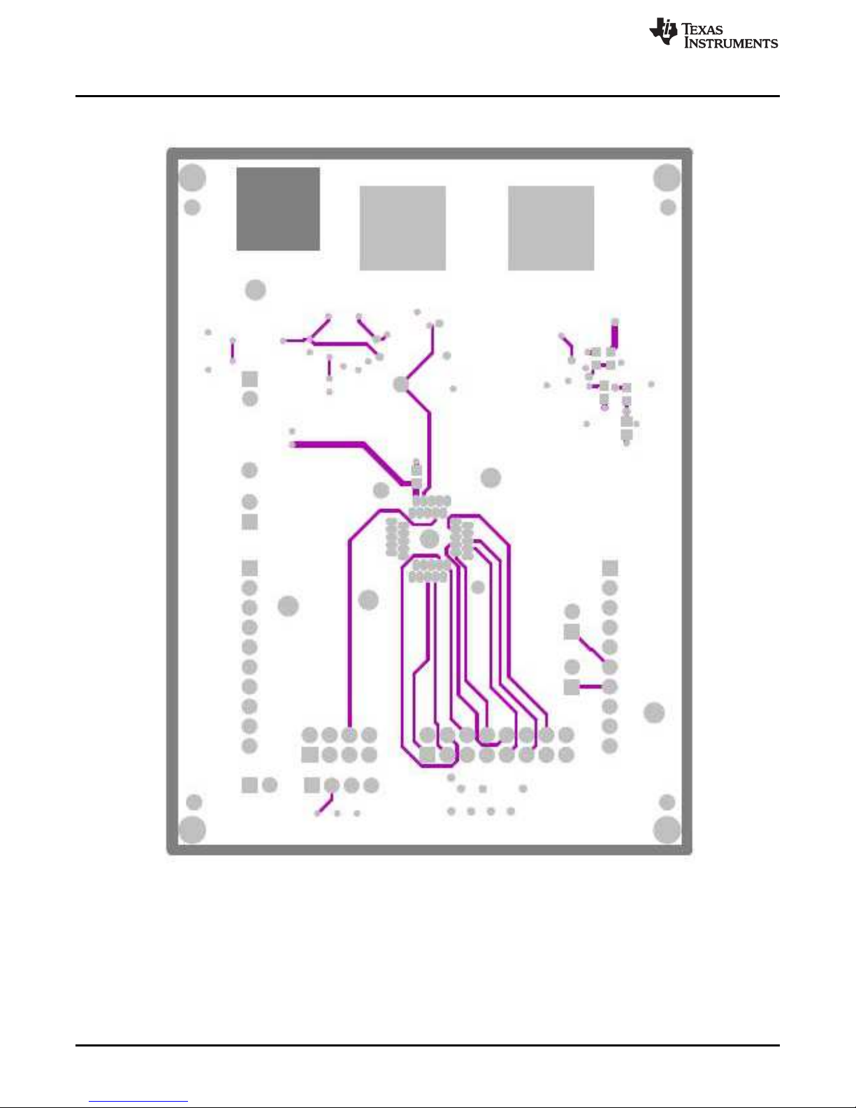
6.2 Printed-Circuit Board (PCB) Layout
Figure 2 to Figure 5 show the PCB layouts for the TCA8424 EVM.
Figure 2. Layer 1 Top Side: 50-Ω Signal Layer
SCDU004–March 2013 TCA8424 Evaluation Module
Submit Documentation Feedback
5
Copyright © 2013, Texas Instruments Incorporated
Page 6
TCA8424 EVM Design Circuitry, Bill of Materials, and Connection Descriptions
www.ti.com
6
TCA8424 Evaluation Module SCDU004–March 2013
Figure 3. Layer 2 (Int1): Ground Plane
Copyright © 2013, Texas Instruments Incorporated
Submit Documentation Feedback
Page 7
www.ti.com
TCA8424 EVM Design Circuitry, Bill of Materials, and Connection Descriptions
Figure 4. Layer 3 (Int2): 50-Ω Signal with Ground Fill
SCDU004–March 2013 TCA8424 Evaluation Module
Submit Documentation Feedback
7
Copyright © 2013, Texas Instruments Incorporated
Page 8
TCA8424 EVM Design Circuitry, Bill of Materials, and Connection Descriptions
www.ti.com
8
TCA8424 Evaluation Module SCDU004–March 2013
Figure 5. Layer 4 Bottom Layer
Copyright © 2013, Texas Instruments Incorporated
Submit Documentation Feedback
Page 9
www.ti.com
TCA8424 EVM Design Circuitry, Bill of Materials, and Connection Descriptions
6.3 Bill of Materials
Table 1 is the bill of materials for this EVM.
Table 1. Bill of Materials
ITEM QTY MFG MFG PART# REF DES DESCRIPTION
1 4 PANASONIC LNJ308G8PRA LED1, LED2, LED3, LED4 LED,SMT,0603,PURE GREEN,2.03V
2 1 POMONA ELECTRONICS 2269-0 J1 DUAL INSULATED BANANA JACKS,
BLACK, 0.75LS
3 1 PANASONIC ECJ-1V41E105M C4, C5, C6, C7, C8, C9, C10, C11, CAPACITOR,SMT,0603,CERAMIC,1.0u
F,25V,20%,X5S
4 1 PANASONIC ECJ-1VB0J106M C12 CAPACITOR,SMT,0603,CERAMIC,10u
F,6.3V,20%,X5R
5 1 TAIYO YUDEN TMK107SD472JA C2 CAPACITOR,SMT,0603,CERAMIC,470
0pF,25V,5%,SD
6 1 VISHAY SPRAGUE 594D687X0010R2T C3 CAP,TAN,SMT,10V,20%, 680uF
7 1 PANASONIC EEFUD0K101R C1 CAP,SMT,ELE,100uf,8V,20%
8 1 DIODES INC B230-13-F CR2 DIODE,SCHOTTKY,SMT, DIODES,INC.
9 1 DIODES INC SD103CW-13-F CR1 SCHOTTKEY
DIODE,SMT,20V,400mW,SOD-123
10 1 SAMTEC TSW-104-07-G-D P2 HEADER,THU,8P,2X4,MALE,DUAL
ROW,100LS,100TL
11 1 SAMTEC TSW-108-07-G-D P1 HEADER,THU,16P,2X8,MALE,DUAL
ROW,100LS,100TL
12 2 FCI 66951-010LF P8, P9 HEADER,THU,10P,1X10,FEMALE,SIN
GLE ROW,100LS,200TL
13 6 SAMTEC TSW-101-07-G-S P3, P4, P5, P6, P10, P11 HEADER,THU,1P,MALE,SINGLE
ROW,100TL
14 5 TE Connectivity 9-146281-0-02 P12, P13, P14, P15, P16
15 1 TE Connectivity 9-146281-0-04 P17
16 1 *ENPLAS CORPORATION QFN-40B-0.5-01 DUT3 HTSOCKET,QFN,40P,35x29x16.7mm,
w 2.1hole
17 1 TI TPS77001DBV U2 1.2~5.5V,ULTRALOW-POWER 50mA
LOW-DROP LINE REGULATOR
18 1 TI TPS27081ADDCR U3 HIGH SIDE LOAD SWITCH WITH LVL
SHFT AND ADJ SLEW RATE
19 1 TI LM2700MTX-ADJ/NOPB U4 LM2700 600KHZ/1.25MHZ,2.5A,
STEPUP PWM DC/DC CONVERTER
20 1 BOURNS SDR0805-100ML L1 INDUCTOR,SMT,2P,POWER,10uH,20
%,RoHS
21 1 VISHAY CRCW060310K0FKEA R21 RESISTOR,SMT,0603,1%,1/10W,10.0K
22 3 VISHAY CRCW0603100KFKEA R10, R11, R12 RESISTOR,SMT,0603,1%,1/10W,100K
23 1 VISHAY CRCW06031K02FKEA R3 RESISTOR,SMT,0603,1%,1/10W,1.02K
24 1 VISHAY CRCW0603150KFKEA R9 RESISTOR,SMT,0603,1%,1/10W,150K
25 1 VISHAY CRCW0603169KFKEA R8 RESISTOR,SMT,0603,1%,1/10W,169K
26 1 VISHAY CRCW060320K0FKEA R15 RESISTOR,SMT,0603,1%,1/10W,20.0K
27 1 VISHAY CRCW06034K64FKEA R2 RESISTOR,SMT,0603,1%,1/10W,4.64K
28 4 PANASONIC ERJ-3GSYJ121 R4,R5, R6, R7 RESISTOR,SMT,0603,5%,1/10W,120
9
SCDU004–March 2013 TCA8424 Evaluation Module
Submit Documentation Feedback
Copyright © 2013, Texas Instruments Incorporated
Page 10

TCA8424 EVM Design Circuitry, Bill of Materials, and Connection Descriptions
www.ti.com
Table 1. Bill of Materials (continued)
29 5 PANASONIC ERJ-3GSYJ122 R16,R17, R18, R19, R20 RESISTOR,SMT,0603,5%,1/10W,1.2K
30 0 BOURNS 3313J-1-204 R14 PlaceHolder, DO NOT INSTALL
32 0 PANASONIC ECJ-1V41E105M C13 PlaceHolder, DO NOT INSTALL
33 1 Texas Instruments TCA8424RHAR U1 TIdevice to be used in Socket
34 5 TE Connectivity 382811-8 N/A Jumpers to be installed over P12, P13,
P14, P15, P16
10
TCA8424 Evaluation Module SCDU004–March 2013
Submit Documentation Feedback
Copyright © 2013, Texas Instruments Incorporated
Page 11

www.ti.com
6.4 VCC and GND Connections
Pin 1 of J1 is a power input to the board and Pin 2 is the GND connection for the board. There are also 4
other GND test points in the corners of the board.
The TCA8424 cannot be powered from the MSP430 Launchpad when programming and needs
an external supply.
Figure 6. VCC and GND Connections
TCA8424 EVM Design Circuitry, Bill of Materials, and Connection Descriptions
6.5 MSP430 Launchpad Interface
Headers P8 and P9 allow the EVM to interface with the MSP430 Launchpad. If not programming a unit,
jumpers P12, P13, P14, and P16 may be installed, header P15 should be removed. When programming a
unit, an external power supply is needed and all headers except P16 should be installed.
SCDU004–March 2013 TCA8424 Evaluation Module
Submit Documentation Feedback
Figure 7. MSP430 Launchpad Interface
11
Copyright © 2013, Texas Instruments Incorporated
Page 12

TCA8424 EVM Design Circuitry, Bill of Materials, and Connection Descriptions
6.6 Breakout Pins
The breakout headers P1 and P2 allow connection of an external keyboard matrix to the EVM. P17 is
connected to the I2C lines of the TCA8424 allowing an external host to communicate to the TCA8424.
www.ti.com
Figure 8. Breakout Pins
Table 2. Header Configurations for P1, P2, and P7
P1 P2 P7
Row15 (pin 16) Row14 Col7 Col6 GND (pin 1)
Row13 Row12 Col5 Col4 /INT
Row11 Row10 Col3 Col2 SDA
Row9 Row8 Col1 Col0 (pin 1) SCL
Row7 Row6
Row5 Row4
Row3 Row2
Row1 Row0 (pin 1)
12
TCA8424 Evaluation Module SCDU004–March 2013
Copyright © 2013, Texas Instruments Incorporated
Submit Documentation Feedback
Page 13

www.ti.com
6.7 LED Outputs
The TCA8424 features LED outputs that are set via the HID SET Report Command in the GUI, discussed
in Section 9, part D.
• Board LED1 = TCA8424 LED0
• Board LED2 = TCA8424 LED1
• Board LED3 = TCA8424 LED2
• Board LED4 = TCA8424 LED3
TCA8424 EVM Design Circuitry, Bill of Materials, and Connection Descriptions
Figure 9. LED Outputs
SCDU004–March 2013 TCA8424 Evaluation Module
Submit Documentation Feedback
13
Copyright © 2013, Texas Instruments Incorporated
Page 14
Launchpad Software Setup
7 Launchpad Software Setup
Use the following steps to set up the Launchpad software:
1. Download Code Composer Studio from the Texas Instruments link.
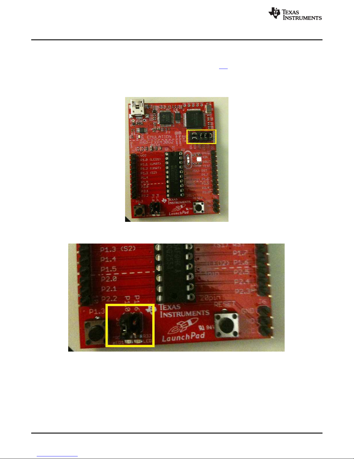
2. With the Launchpad unplugged, configure the headers on the Launchpad to match the yellow box in
the image below:
• The right 3 headers are vertical and the left 2 are horizontal
www.ti.com
3. With the Launchpad still unplugged, remove the right-most jumper on the J5 header to match the
yellow box below:
14
TCA8424 Evaluation Module SCDU004–March 2013
Copyright © 2013, Texas Instruments Incorporated
Submit Documentation Feedback
Page 15

www.ti.com
4. Connect the Launchpad to your computer with a USB to mini cable. A green LED and a red LED
5. Open Code Composer Studio and create a new workspace. Select the “Project” drop down menu and
6. After completing steps 1–5, to load the code at any point for any reason, simply open the workspace
If the Launchpad is running and VCC is not connected, the I2C communication will fail. You must
pause the debugger, reset the MSP430 with the "reset CPU" button and then press “play” again.
Launchpad Software Setup
should be on as shown below:
click on “Import existing CCS/CCE Eclipse Project.” Select Browse on the “Select-search directory”
option and select the location where the source code is stored. Click "Finish" and then select “debug
launch” to load the code to the MSP430G2553 microcontroller. Once completed, disconnect the USB
cable from the LaunchPad.
that was created. Ensure that the source code is the active project and the LaunchPad is connected
through USB. Then select “debug launch” to load the code.
SCDU004–March 2013 TCA8424 Evaluation Module
Submit Documentation Feedback
15
Copyright © 2013, Texas Instruments Incorporated
Page 16

GUI Software Setup
8 GUI Software Setup
1. Extract the “TCA8424 GUI.zip” contents to the destination folder of your choice.
2. Double click the setup.exe folder that was extracted in step 1.
3. The following window pops up. Click “Install”.
4. After finishing the installation, the GUI opens and looks like this:
www.ti.com
5. To open the GUI in the future, simply double click on the “TCA8424 G.application” file that was
unzipped in step 1.
16
TCA8424 Evaluation Module SCDU004–March 2013
Copyright © 2013, Texas Instruments Incorporated
Submit Documentation Feedback
Page 17

www.ti.com
9 GUI Walkthrough Guide
A. Connecting the Launchpad to the EVM and PC
1. Install all headers except P16, place an un-programmed TCA8424 in the socket, and power the EVM
board with 3.3 V.
2. Connect the MSP430 Launchpad to the EVM as shown below:
• The connection point is under the board and the USB connector should open towards J1.
3. Connect the Launchpad to your PC.
B. Initiating the connection from the GUI to the Launchpad
1. Open up the device manager on your PC and find which of the COM ports is associated with the
Launchpad.
• COM15 is the COM port associated with Launchpad as shown in the below image (using a local
installation for illustration purposes only):
GUI Walkthrough Guide
2. Open the GUI.
SCDU004–March 2013 TCA8424 Evaluation Module
Submit Documentation Feedback
17
Copyright © 2013, Texas Instruments Incorporated
Page 18

GUI Walkthrough Guide
3. Under the "Select Port", there is a drop down menu box which is blank on startup, by default, as
shown below:
4. Click this box, and a list of COM ports will pop up. Select the COM port that is associated with the
Launchpad which was identified in step 1.
• COM 15 from a local installation is shown for illustration purposes:
www.ti.com
18
TCA8424 Evaluation Module SCDU004–March 2013
Copyright © 2013, Texas Instruments Incorporated
Submit Documentation Feedback
Page 19

www.ti.com
5. Now the GUI has opened a connection to the Launchpad and the COM port remains in the drop down
GUI Walkthrough Guide
menu box as shown below:
After the connection the Launchpad has been established and the GUI can be fully utilized. The remaining
sections give basic steps on how to use each of the GUI buttons and inputs.
C. Changing the I2C Address
The I2C address in this GUI is referenced with the Read and Write bit included. An address of 0xA8 is
represented in binary as 1010100Xb with the last bit being a 'don’t care'. Address 0xA8 and 0xA9 are both
interpreted as the same address.
The GUI indicates whether an I2C Nack is received by the Launchpad, by presenting a dialog box like
shown below:
SCDU004–March 2013 TCA8424 Evaluation Module
Submit Documentation Feedback
19
Copyright © 2013, Texas Instruments Incorporated
Page 20

GUI Walkthrough Guide
1. Both the Launchpad and GUI default the I2C addresses to 0x76 on startup as shown below:
www.ti.com
2. The I2C address must be written into the text box in the default format. Once an address has been
entered, simply click on the “Change I2C address” button to communicate this to the Launchpad.
• If the Launchpad is restarted, the I2C address will default again to 0x76 and must be changed
again if you are working with a different I2C address.
3. Since the default address of the TCA8424 is 0x76 when the OTP is not programmed, leave the default
address in the Launchpad.
20
TCA8424 Evaluation Module SCDU004–March 2013
Copyright © 2013, Texas Instruments Incorporated
Submit Documentation Feedback
Page 21

www.ti.com
D. HID commands and Read Report
1. The LED outputs can be changed using the HID Command “SET Report” in the GUI which replicates
GUI Walkthrough Guide
an HID host issuing the command. The LED values are off, by default, and are changed by clicking the
LED buttons.
2. The LED inputs for the SET Report command change to read ‘1’ with a green background when
clicked, and change back to ‘0’ with a red background when clicked again.
3. After inputting the LED values to be set, click the “SET Report button to set the output report and the
LED’s turn on.
SCDU004–March 2013 TCA8424 Evaluation Module
Submit Documentation Feedback
21
Copyright © 2013, Texas Instruments Incorporated
Page 22

GUI Walkthrough Guide
www.ti.com
4. Clicking the “Set Power Sleep” issues the SET POWER = WAKE HID Command and puts the device
to sleep. If the LED outputs are turned on when this command is issued, they will now turn off.
5. Issuing the SET POWER = WAKE command turns the LED’s back on after a Sleep command has
been issued. This is done by clicking the “Set Power Wake” command
6. The “Reset” button issues the RESET HID Command and the device resets, this clears the output
report. If LED’s were on previously, then they will turn off after this command is received.
22
TCA8424 Evaluation Module SCDU004–March 2013
Copyright © 2013, Texas Instruments Incorporated
Submit Documentation Feedback
Page 23

www.ti.com
7. The “Get Report” button issues the HID command GET REPORT. This retrieves the current contents
GUI Walkthrough Guide
of the input report and populates the text box below the button (red box). The GET REPORT
command does not clear an interrupt.
For more information on how HID commands operate and the TCA8424’s device behavior,
please see the “COMMAND and DATA REGISTER” section of the datasheet.
8. The “Read Report” button issues an unaddressed read command to the TCA8424. It populates the
same text box as the “Get Report” button does with the contents of the input report, but it will clear an
asserted interrupt.
For more information on the Input Report behavior please see the “INPUT REPORT” section of the
datasheet.
SCDU004–March 2013 TCA8424 Evaluation Module
Submit Documentation Feedback
23
Copyright © 2013, Texas Instruments Incorporated
Page 24

GUI Walkthrough Guide
E. Programming and verifying the OTP contents
1. The first thing that must be created is the .csv file that contains the OTP contents. If this has been
created skip to step 2.
(a) Open an excel workbook with a single column for the OTP contents.
• The image below shows a properly formatted excel file with the blue box indicating a break in
the 512 byte contents:
www.ti.com
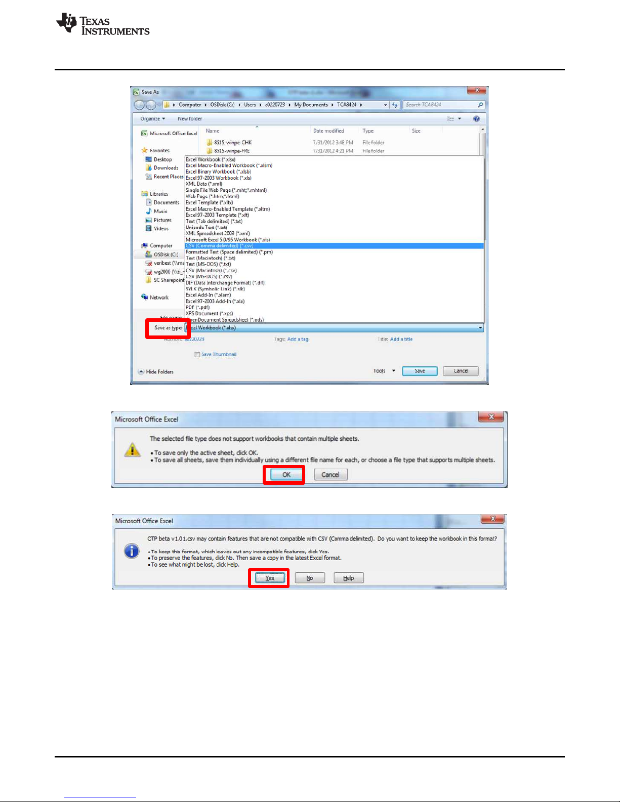
(b) Click the "Office" button and then click “Save as”.
(c) In the Save as window that pops up, choose the “CSV (Comma delimited) (*csv)” option under the
“Save as type” menu (indicated by red box):
24
TCA8424 Evaluation Module SCDU004–March 2013
Copyright © 2013, Texas Instruments Incorporated
Submit Documentation Feedback
Page 25
www.ti.com
GUI Walkthrough Guide
(d) Click “Save” and click "OK" to the message that pops up:
(e) Click "Yes" to the next dialog box that opens:
SCDU004–March 2013 TCA8424 Evaluation Module
Submit Documentation Feedback
25
Copyright © 2013, Texas Instruments Incorporated
Page 26

GUI Walkthrough Guide
(f) Exit the .csv file and click "Yes" to the two dialog boxes that show up as shown below:
2. Now that we have a .csv, the OTP contents can be programmed. Click the “Load OTP” button as
shown below:
www.ti.com
26
TCA8424 Evaluation Module SCDU004–March 2013
Copyright © 2013, Texas Instruments Incorporated
Submit Documentation Feedback
Page 27

www.ti.com
3. This opens a Windows®Explorer window that shows only .csv files. Navigate to the .csv file created
GUI Walkthrough Guide
earlier:
4. This populates the text box above the “Load OTP” button with the contents of the .csv file. This text
box is fully editable, as long as the contents remain in the same format.
SCDU004–March 2013 TCA8424 Evaluation Module
Submit Documentation Feedback
27
Copyright © 2013, Texas Instruments Incorporated
Page 28

GUI Walkthrough Guide
5. Now choose a start location for our OTP programming and the number of bytes to program.
(a) The start location should be formatted as below and has no default contents. You must enter a
value before programming the OTP.
www.ti.com
(b) The number of bytes is defaulted to the value “512” and should be entered as a decimal value in
the text box, if it needs to be changed.
6. Now that the start location, number of bytes, and the OTP contents are in place, we are ready to
program the OTP. Upon completion, the following dialog box should appear:
7. The first byte of the OTP (Address 0x0000) contains the I2C address for the device including the R/W
bit. The R/W bit of the I2C address must be programmed to a ‘1’ for the OTP contents to be
used. If a ‘0’ is programmed at this bit, the OTP will program but the contents will not load into
the digital core.
28
TCA8424 Evaluation Module SCDU004–March 2013
Copyright © 2013, Texas Instruments Incorporated
Submit Documentation Feedback
Page 29

www.ti.com
8. Because we have now programmed a new I2C address into the device, we must change the I2C
GUI Walkthrough Guide
address in the Launchpad with the Change I2C address button.
• In this case it will now be 0x91 as shown below:
9. Now that the OTP contents are changed and the I2C address in the Launchpad is set, confirm that
what was actually programmed, matches what we tried to program.
(a) Click on the “Read OTP” button to read back the OTP contents in the device and populate the
textbox above the “Read OTP” button as shown below:
SCDU004–March 2013 TCA8424 Evaluation Module
Submit Documentation Feedback
29
Copyright © 2013, Texas Instruments Incorporated
Page 30

Related Documentation
(b) Now compare the contents to be programmed with the current OTP contents by clicking the
“Compare OTP” button. If the "Contents to be Programmed" and the "Current OTP Contents" are
the same, the dialog below the “Compare OTP” button changes accordingly, as shown below:
www.ti.com
The Compare OTP button assumes the "Contents to be Programmed" and "Current OTP Contents"
are the same length. They must match exactly for dialog box to change to “Match”.
After Programming the OTP, the device will be in "TEST" mode until powered down and then
powered up again. This causes increased ICC outside of datasheet specifications. Once power
cycled, the device ICC returns to normal.
10 Related Documentation
TCA8424 Low-Voltage 8x16 Keyboard Scanner with HID over I2C Compliant Interface Datasheet
(SCDS341)
30
TCA8424 Evaluation Module SCDU004–March 2013
Copyright © 2013, Texas Instruments Incorporated
Submit Documentation Feedback
Page 31

IMPORTANT NOTICE
Texas Instruments Incorporated and its subsidiaries (TI) reserve the right to make corrections, enhancements, improvements and other
changes to its semiconductor products and services per JESD46, latest issue, and to discontinue any product or service per JESD48, latest
issue. Buyers should obtain the latest relevant information before placing orders and should verify that such information is current and
complete. All semiconductor products (also referred to herein as “components”) are sold subject to TI’s terms and conditions of sale
supplied at the time of order acknowledgment.
TI warrants performance of its components to the specifications applicable at the time of sale, in accordance with the warranty in TI’s terms
and conditions of sale of semiconductor products. Testing and other quality control techniques are used to the extent TI deems necessary
to support this warranty. Except where mandated by applicable law, testing of all parameters of each component is not necessarily
performed.
TI assumes no liability for applications assistance or the design of Buyers’ products. Buyers are responsible for their products and
applications using TI components. To minimize the risks associated with Buyers’ products and applications, Buyers should provide
adequate design and operating safeguards.
TI does not warrant or represent that any license, either express or implied, is granted under any patent right, copyright, mask work right, or
other intellectual property right relating to any combination, machine, or process in which TI components or services are used. Information
published by TI regarding third-party products or services does not constitute a license to use such products or services or a warranty or
endorsement thereof. Use of such information may require a license from a third party under the patents or other intellectual property of the
third party, or a license from TI under the patents or other intellectual property of TI.
Reproduction of significant portions of TI information in TI data books or data sheets is permissible only if reproduction is without alteration
and is accompanied by all associated warranties, conditions, limitations, and notices. TI is not responsible or liable for such altered
documentation. Information of third parties may be subject to additional restrictions.
Resale of TI components or services with statements different from or beyond the parameters stated by TI for that component or service
voids all express and any implied warranties for the associated TI component or service and is an unfair and deceptive business practice.
TI is not responsible or liable for any such statements.
Buyer acknowledges and agrees that it is solely responsible for compliance with all legal, regulatory and safety-related requirements
concerning its products, and any use of TI components in its applications, notwithstanding any applications-related information or support
that may be provided by TI. Buyer represents and agrees that it has all the necessary expertise to create and implement safeguards which
anticipate dangerous consequences of failures, monitor failures and their consequences, lessen the likelihood of failures that might cause
harm and take appropriate remedial actions. Buyer will fully indemnify TI and its representatives against any damages arising out of the use
of any TI components in safety-critical applications.
In some cases, TI components may be promoted specifically to facilitate safety-related applications. With such components, TI’s goal is to
help enable customers to design and create their own end-product solutions that meet applicable functional safety standards and
requirements. Nonetheless, such components are subject to these terms.
No TI components are authorized for use in FDA Class III (or similar life-critical medical equipment) unless authorized officers of the parties
have executed a special agreement specifically governing such use.
Only those TI components which TI has specifically designated as military grade or “enhanced plastic” are designed and intended for use in
military/aerospace applications or environments. Buyer acknowledges and agrees that any military or aerospace use of TI components
which have not been so designated is solely at the Buyer's risk, and that Buyer is solely responsible for compliance with all legal and
regulatory requirements in connection with such use.
TI has specifically designated certain components as meeting ISO/TS16949 requirements, mainly for automotive use. In any case of use of
non-designated products, TI will not be responsible for any failure to meet ISO/TS16949.
Products Applications
Audio www.ti.com/audio Automotive and Transportation www.ti.com/automotive
Amplifiers amplifier.ti.com Communications and Telecom www.ti.com/communications
Data Converters dataconverter.ti.com Computers and Peripherals www.ti.com/computers
DLP® Products www.dlp.com Consumer Electronics www.ti.com/consumer-apps
DSP dsp.ti.com Energy and Lighting www.ti.com/energy
Clocks and Timers www.ti.com/clocks Industrial www.ti.com/industrial
Interface interface.ti.com Medical www.ti.com/medical
Logic logic.ti.com Security www.ti.com/security
Power Mgmt power.ti.com Space, Avionics and Defense www.ti.com/space-avionics-defense
Microcontrollers microcontroller.ti.com Video and Imaging www.ti.com/video
RFID www.ti-rfid.com
OMAP Applications Processors www.ti.com/omap TI E2E Community e2e.ti.com
Wireless Connectivity www.ti.com/wirelessconnectivity
Mailing Address: Texas Instruments, Post Office Box 655303, Dallas, Texas 75265
Copyright © 2015, Texas Instruments Incorporated
Page 32

Mouser Electronics
Authorized Distributor
Click to View Pricing, Inventory, Delivery & Lifecycle Information:
Texas Instruments:
TCA8424EVM-038
 Loading...