

Page 1

H.264 High Profile Encoder on
TMS320C6678 Platform
User’s Guide
Literature Number: SPRUHL4
December 2012
Page 2

IMPORTANT NOTICE
Texas Instruments Incorporated and its subsidiaries (TI) reserve the right to make corrections, enhancements, improvements and other changes to
its semiconductor products and services per JESD46, latest issue, and to discontinue any product or service per JESD48, latest issue. Buyers
should obtain the latest relevant information before placing orders and should verify that such information is current and complete. All
semiconductor products (also referred to herein as “components”) are sold subject to TI’s terms and conditions of sale supplied at the time of order
acknowledgment.
TI warrants performance of its components to the specifications applicable at the time of sale, in accordance with the warranty in TI’s terms and
conditions of sale of semiconductor products. Testing and other quality control techniques are used to the extent TI deems necessary to support
this warranty. Except where mandated by applicable law, testing of all parameters of each component is not necessarily performed.
TI assumes no liability for applications assistance or the design of Buyers’ products. Buyers are responsible for their products and applications
using TI components. To minimize the risks associated with Buyers’ products and applications, Buyers should provide adequate design and
operating safeguards.
TI does not warrant or represent that any license, either express or implied, is granted under any patent right, copyright, mask work right, or
other intellectual property right relating to any combination, machine, or process in which TI components or services are used. Information
published by TI regarding third-party products or services does not constitute a license to use such products or services or a warranty or
endorsement thereof. Use of such information may require a license from a third party under the patents or other intellectual property of the third
party, or a license from TI under the patents or other intellectual property of TI.
Reproduction of significant portions of TI information in TI data books or data sheets is permissible only if reproduction is without alteration and
is accompanied by all associated warranties, conditions, limitations, and notices. TI is not responsible or liable for such altered documentation.
Information of third parties may be subject to additional restrictions.
Resale of TI components or services with statements different from or beyond the parameters stated by TI for that component or service voids all
express and any implied warranties for the associated TI component or service and is an unfair and deceptive business practice. TI is not
responsible or liable for any such statements.
Buyer acknowledges and agrees that it is solely responsible for compliance with all legal, regulatory and safety-related requirements concerning
its products, and any use of TI components in its applications, notwithstanding any applications-related information or support that may be
provided by TI. Buyer represents and agrees that it has all the necessary expertise to create and implement safeguards which anticipate
dangerous consequences of failures, monitor failures and their consequences, lessen the likelihood of failures that might cause harm and take
appropriate remedial actions. Buyer will fully indemnify TI and its representatives against any damages arising out of the use of any TI
components in safety-critical applications.
In some cases, TI components may be promoted specifically to facilitate safety-related applications. With such components, TI’s goal is to help
enable customers to design and create their own end-product solutions that meet applicable functional safety standards and requirements.
Nonetheless, such components are subject to these terms.
No TI components are authorized for use in FDA Class III (or similar life-critical medical equipment) unless authorized officers of the parties
have executed a special agreement specifically governing such use.
Only those TI components which TI has specifically designated as military grade or “enhanced plastic” are designed and intended for use in
military/aerospace applications or environments. Buyer acknowledges and agrees that any military or aerospace use of TI components
which have not been so designated is solely at the Buyer's risk, and that Buyer is solely responsible for compliance with all legal and
regulatory requirements in connection with such use.
TI has specifically designated certain components as meeting ISO/TS16949 requirements, mainly for automotive use. In any case of use of
non-designated products, TI will not be responsible for any failure to meet ISO/TS16949.
Products Applications
Audio www.ti.com/audio Automotive & Transportation www.ti.com/automotive
Amplifiers amplifier.ti.com Communications & Telecom www.ti.com/communications
Data Converters dataconverter.ti.com Computers & Peripherals www.ti.com/computers
DLP® Products www.dlp.com Consumer Electronics www.ti.com/consumer-apps
DSP dsp.ti.com Energy and Lighting www.ti.com/energyapps
Clocks and Timers www.ti.com/clocks Industrial www.ti.com/industrial
Interface interface.ti.com Medical www.ti.com/medical
Logic logic.ti.com Security www.ti.com/security
Power Mgmt power.ti.com Space, Avionics & Defense www.ti.com/space-avionics-defense
Microcontrollers microcontroller.ti.com Video & Imaging www.ti.com/video
RFID www.ti-rfid.com
OMAP Applications Processors www.ti.com/omap TI E2E Community e2e.ti.com
Wireless Connectivity www.ti.com/wirelessconnectivity
Mailing Address: Texas Instruments, Post Office Box 655303, Dallas, Texas 75265
Copyright© 2012, Texas Instruments Incorporated
Page 3

Preface
Read This First
About This Manual
This document describes how to install and work with Texas Instruments’ (TI) H.264 High Profile
Encoder implementation on the TMS320C6678 platform. It also provides a detailed Application
Programming Interface (API) reference and information on the sample application that accompanies
this component.
TI’s codec implementations are based on the eXpressDSP Digital Media (XDM) standard. XDM is
an extension of the eXpressDSP Algorithm Interface Standard (XDAIS).
Intended Audience
This document is intended for system engineers who want to integrate TI’s codecs with other
software to build a multimedia system based on the TMS320C6678 and Visual C.
This document assumes that you are fluent in the C language, have a good working knowledge of
Digital Signal Processing (DSP), digital signal processors, and DSP applications. Good knowledge
of eXpressDSP Algorithm Interface Standard (XDAIS) and eXpressDSP Digital Media (XDM)
standard will be helpful.
How to Use This Manual
This document includes the following chapters:
Chapter 1 - Introduction, provides a brief introduction to the XDAIS and
XDM standards. It also provides an overview of the codec and lists its
supported features.
Chapter 2 - Installation Overview, describes how to install, build, and run
the codec.
Chapter 3 - Sample Usage, describes the sample usage of the codec.
Chapter 4 - API Reference, describes the data structures and interface
functions used in the codec.
Chapter 5 - Frequently Asked Questions, provides answers to few
frequently asked questions related to using this encoder.
iii
Appendix A – Debug Trace Support, describs the method to use H264
encoder debug and trace mechanism.
Appendix B - Call Back function for NAL Units, describes the Call
back function that provides compressed bit-streams at NAL level.
Page 4

Read This First
Related Documentation From Texas Instruments
The following documents describe TI’s DSP algorithm standards such as, XDAIS and XDM. To
obtain a copy of any of these TI documents, visit the Texas Instruments website at www.ti.com.
TMS320 DSP Algorithm Standard Rules and Guidelines (literature number
SPRU352) defines a set of requirements for DSP algorithms that, if
followed, allow system integrators to quickly assemble production-quality
systems from one or more such algorithms.
TMS320 DSP Algorithm Standard API Reference (literature number
SPRU360) describes all the APIs that are defined by the TMS320 DSP
Algorithm Interface Standard (also known as XDAIS) specification.
Technical Overview of eXpressDSP - Compliant Algorithms for DSP
Software Producers (literature number SPRA579) describes how to make
algorithms compliant with the TMS320 DSP Algorithm Standard which is
part of TI’s eXpressDSP technology initiative.
Using the TMS320 DSP Algorithm Standard in a Static DSP System
(literature number SPRA577) describes how an eXpressDSP-compliant
algorithm may be used effectively in a static system with limited memory.
Using IRES and RMAN Framework Components for C64x+ (literature
number SPRAAI5), describes the IRES interface definition and function
calling sequence.
eXpressDSP Digital Media (XDM) Standard API Reference (literature
number SPRUEC8)
Related Documentation
You can use the following documents to supplement this user guide:
ITU-T Rec. H.264 | ISO/IEC 14496-10 AVC - Draft ITU-T Recommendation
and Final Draft International Standard of Joint Video Specification
iv
Page 5

Read This First
Abbreviation
Description
AIR
Adaptive Intra Fresh
API
Application Programming Interface
AVC
Advanced Video Coding
CAVLC
Context Adaptive Variable Length Coding
CIF
Common Intermediate Format
COFF
Common Object File Format
DMA
Direct Memory Access
DMAN3
DMA Manager
DSP
Digital Signal Processing
EVM
Evaluation Module
GOP
Group Of Pictures
IDR
Instantaneous Decoding Refresh
IRES
Interface for Resources
NAL
Network Abstraction Layer
PPS
Picture Parameter Set
QCIF
Quarter Common Intermediate Format
QP
Quantization Parameter
QVGA
Quarter Video Graphics Array
RMAN
Resource Manager
SPS
Sequence Parameter Set
SQCIF
Sub Quarter Common Intermediate Format
VGA
Video Graphics Array
Abbreviations
The following abbreviations are used in this document.
Table 0-1 List of Abbreviations
v
Page 6

Read This First
Abbreviation
Description
XDAIS
eXpressDSP Algorithm Interface Standard
XDM
eXpressDSP Digital Media
Text Conventions
The following conventions are used in this document:
Text inside back-quotes (‘‘) represents pseudo-code.
Program source code, function and macro names, parameters, and
command line commands are shown in a mono-spaced font.
Product Support
When contacting TI for support on this codec, quote the product name (H.264 High Profile Encoder
on TMS320C6678 platform) and version number. The version number of the codec is included in
the Title of the Release Notes that accompanies this codec.
Trademarks
Code Composer Studio, DSP/BIOS, eXpressDSP, TMS320, TMS320C64x, TMS320C6000,
TMS320C6678, and TMS320C64x+ are trademarks of Texas Instruments.
All trademarks are the property of their respective owners.
vi
Page 7

Contents
H.264 HIGH PROFILE ENCODER ON TMS320C6678 PLATFORM ................................................................. 1-1
READ THIS FIRST ......................................................................................................................................... III
ABOUT THIS MANUAL ......................................................................................................................................... III
INTENDED AUDIENCE .......................................................................................................................................... III
HOW TO USE THIS MANUAL ................................................................................................................................ III
RELATED DOCUMENTATION FROM TEXAS INSTRUMENTS ........................................................................................... IV
RELATED DOCUMENTATION ................................................................................................................................. IV
ABBREVIATIONS .................................................................................................................................................. V
TEXT CONVENTIONS ........................................................................................................................................... VI
PRODUCT SUPPORT ............................................................................................................................................ VI
TRADEMARKS .................................................................................................................................................... VI
CONTENTS ................................................................................................................................................. VII
FIGURES ...................................................................................................................................................... IX
TABLES ....................................................................................................................................................... XI
INTRODUCTION ........................................................................................................................................ 1-1
1.1 OVERVIEW OF XDAIS, XDM, AND IRES .....................................................................................................1-2
1.1.1 XDAIS Overview ........................................................................................................................1-2
1.1.2 XDM Overview ..........................................................................................................................1-2
1.1.3 IRES Overview ...........................................................................................................................1-3
1.2 OVERVIEW OF H.264 HIGH PROFILE ENCODER ............................................................................................1-4
1.3 SUPPORTED SERVICES AND FEATURES .........................................................................................................1-6
INSTALLATION OVERVIEW ........................................................................................................................ 2-1
2.1 SYSTEM REQUIREMENTS ..........................................................................................................................2-2
2.1.1 Hardware .................................................................................................................................2-2
2.1.2 Software ...................................................................................................................................2-2
2.2 INSTALLING THE COMPONENT ...................................................................................................................2-2
2.2.1 Installing the Component – RTSC Package ...............................................................................2-2
2.2.2 Installing the Component – Compressed archive .....................................................................2-4
2.3 BEFORE BUILDING THE ALGORITHM LIBRARY AND SAMPLE TEST APPLICATION ....................................................2-9
2.3.1 Installing XDAIS tools(XDAIS) ...................................................................................................2-9
2.3.2 Installing XDC Tools ..................................................................................................................2-9
2.3.3 Installing BIOS tools(SYS/BIOS) ..............................................................................................2-10
2.3.4 Installing Framework Component(FC) ....................................................................................2-10
2.3.5 Installing EDMA3 Low-Level Driver(LLD) ................................................................................2-10
2.3.6 Installing Inter Processor Communication (IPC) .....................................................................2-10
2.4 BUILDING THE ALGORITHM LIBRARY .........................................................................................................2-10
2.4.1 Building Algorithm Library on Visual studio ...........................................................................2-10
2.4.2 Building Algorithm Library on Code Composer Studio ...........................................................2-11
2.5 BUILDING SAMPLE TEST APPLICATION.......................................................................................................2-11
vii
Page 8

2.5.1 Building Sample Test Application on Visual Studio ................................................................2-11
2.5.2 Building the Sample Test Application on Code Composer Studio – Compressed archive .......2-12
2.5.3 Building the Sample Test Application on Code Composer Studio - RTSC Package.................2-12
2.6 RUNNING SAMPLE TEST APPLICATION.......................................................................................................2-13
2.6.1 Running the Sample Test Application on Visual Studio ..........................................................2-13
2.6.2 Running the Sample Test Application on Code Composer Studio ...........................................2-14
2.7 CONFIGURATION FILES ...........................................................................................................................2-15
2.7.1 Encoder Configuration File .....................................................................................................2-15
2.8 UNINSTALLING THE COMPONENT .............................................................................................................2-18
SAMPLE USAGE ........................................................................................................................................ 3-1
3.1 OVERVIEW OF THE TEST APPLICATION.........................................................................................................3-2
3.1.1 Parameter Setup ......................................................................................................................3-3
3.1.2 Algorithm Instance Creation and Initialization ........................................................................3-3
3.1.3 Process Call...............................................................................................................................3-4
3.1.4 Algorithm Instance Deletion .....................................................................................................3-5
3.2 FRAME BUFFER MANAGEMENT .................................................................................................................3-5
3.2.1 Input Frame Buffer ...................................................................................................................3-5
API REFERENCE ......................................................................................................................................... 4-1
4.1 SYMBOLIC CONSTANTS AND ENUMERATED DATA TYPES .................................................................................4-2
4.1.1 Common XDM Data types ........................................................................................................4-2
4.1.2 Common Multi-Core Data types .............................................................................................4-24
4.2 DATA STRUCTURES ...............................................................................................................................4-28
4.2.1 Common XDM Data Structures ..............................................................................................4-28
4.2.2 Common Multi-core Data Structures .....................................................................................4-46
4.2.3 H.264 High Profile Encoder Data Structures ..........................................................................4-48
4.3 DEFAULT AND SUPPORTED VALUES OF PARAMETERS ...................................................................................4-64
4.4 INTERFACE FUNCTIONS ..........................................................................................................................4-74
4.4.1 Creation APIs ..........................................................................................................................4-75
4.4.2 Initialization API .....................................................................................................................4-77
4.4.3 Control API .............................................................................................................................4-79
4.4.4 Data Processing API ...............................................................................................................4-80
4.4.5 Termination API ......................................................................................................................4-86
FREQUENTLY ASKED QUESTIONS .............................................................................................................. 5-1
5.1 CODE BUILD AND EXECUTION ....................................................................................................................5-1
5.2 ALGORITHM RELATED ..............................................................................................................................5-1
DEBUG TRACE SUPPORT ........................................................................................................................... 5-1
A.1 DEBUG TRACE DESIGN IN ENCODER .......................................................................................................5-1
A.2 STEPS TO UTILIZE DEBUG TRACE SUPPORT IN H264 HIGH PROFILE ENCODER ..................................................5-1
CALL BACK FUNCTION FOR NAL UNITS ...................................................................................................... B-1
viii
Page 9

Figures
FIGURE 1-1 XDM INTRODUCTION ...................................................................................................................1-3
FIGURE 1-2 IRES INTERFACE DEFINITION AND FUNCTION CALLING SEQUENCE ..........................................1-4
FIGURE 1-3 WORKING OF H.264 VIDEO ENCODER ........................................................................................1-5
FIGURE 2-1 COMPONENT DIRECTORY STRUCTURE IN CASE OF RTSC PACKAGE RELEASE ........................2-3
FIGURE 2-2 COMPONENT DIRECTORY STRUCTURE IN CASE OF OBJECT RELEASE ......................................2-5
FIGURE 2-3 COMPONENT DIRECTORY STRUCTURE IN CASE OF SOURCE RELEASE .....................................2-7
FIGURE 3-1 TEST APPLICATION SAMPLE IMPLEMENTATION ...........................................................................3-2
FIGURE 5-1 OVERVIEW OF CALLBACK FUNCTION. ......................................................................................... B-1
FIGURE 5-3 OVERVIEW OF COPYING .............................................................................................................. B-2
ix
Page 10

This page is intentionally left blank
x
Page 11

Tables
TABLE 0-1 LIST OF ABBREVIATIONS ................................................................................................................... V
TABLE 2-1 COMPONENT DIRECTORIES IN CASE OF RTSC PACKAGE RELEASE.............................................2-3
TABLE 2-2 COMPONENT DIRECTORIES IN CASE OF OBJECT RELEASE ..........................................................2-5
TABLE 2-3 COMPONENT DIRECTORIES IN CASE OF SOURCE RELEASE .........................................................2-7
TABLE 4-1 LIST OF ENUMERATED DATA TYPES .............................................................................................4-2
TABLE 4-2 H264 HIGH PROFILE ENCODER SPECIFIC ENUMERATED DATA TYPES .....................................4-11
TABLE 4-3 H264 ENCODER CONSTANTS .....................................................................................................4-21
TABLE 4-4 H.264 ENCODER ERROR STATUSES ..........................................................................................4-21
TABLE 4-5 DEFAULT AND SUPPORTED VALUES FOR IVIDENC2_PARAMS.................................................4-64
TABLE 4-6 DEFAULT AND SUPPORTED VALUES FOR IVIDENC2_DYNAMICPARAMS .................................4-66
TABLE 4-7 DEFAULT AND SUPPORTED VALUES FOR IH264HPVENC_RATECONTROLPARAMS...............4-67
TABLE 4-8 DEFAULT AND SUPPORTED VALUES FOR IH264HPVENC_INTERCODINGPARAMS .................4-68
TABLE 4-9 DEFAULT AND SUPPORTED VALUES FOR IH264HPVENC_INTRACODINGPARAMS .................4-68
TABLE 4-10 DEFAULT AND SUPPORTED VALUES FOR IH264HPVENC_SLICECODINGPARAMS...............4-69
TABLE 4-11 DEFAULT AND SUPPORTED VALUES FOR IH264HPVENC_LOOPFILTERPARAMS ...............4-70
TABLE 4-12 DEFAULT AND SUPPORTED VALUES FOR IH264HPVENC_VUICODINGPARAMS ..................4-70
TABLE 4-13 DEFAULT AND SUPPORTED VALUES FOR IH264HPVENC_PARAMS......................................4-71
TABLE 4-14 DEFAULT AND SUPPORTED VALUES FOR IH264HPVENC_DYNAMICPARAMS .............................................4-73
xi
Page 12

This page is intentionally left blank
xii
Page 13

Introduction
1.1 Overview of XDAIS, XDM, and IRES
1-2
1.2 Overview of H.264 High Profile Encoder
1-4
1.3 Supported Services and Features
1-6
Chapter 1
Introduction
This chapter provides a brief introduction to XDAIS and XDM. It also provides an overview of TI’s
implementation of the H.264 High Profile Encoder on the TMS320C6678 platform and its supported
features.
Topic Page
1-1
Page 14

Introduction
1.1 Overview of XDAIS, XDM, and IRES
TI’s multimedia codec implementations are based on the eXpressDSP Digital Media (XDM)
standard. XDM is an extension of the eXpressDSP Algorithm Interface Standard (XDAIS). IRES is
the interface for management and utilization of special resource types such as hardware
accelerators, certain types of memory, and DMA. This interface allows the client application to
query and provide the algorithm its requested resources.
1.1.1 XDAIS Overview
An eXpressDSP-compliant algorithm is a module that implements the abstract interface IALG. The
IALG API takes the memory management function away from the algorithm and places it in the
hosting framework. Thus, an interaction occurs between the algorithm and the framework. This
interaction allows the client application to allocate memory for the algorithm and also share memory
between algorithms. It also allows the memory to be moved around while an algorithm is operating
in the system. In order to facilitate these functionalities, the IALG interface defines the following
APIs:
algAlloc()
algInit()
algActivate()
algDeactivate()
algFree()
The algAlloc() API allows the algorithm to communicate its memory requirements to the client
application. The algInit() API allows the algorithm to initialize the memory allocated by the client
application. The algFree() API allows the algorithm to communicate the memory to be freed when
an instance is no longer required.
Once an algorithm instance object is created, it can be used to process data in real-time. The
algActivate() API provides a notification to the algorithm instance that one or more algorithm
processing methods is about to be run zero or more times in succession. After the processing
methods have been run, the client application calls the algDeactivate() API prior to reusing any
of the instance’s scratch memory.
The IALG interface also defines three more optional APIs algControl(), algNumAlloc(), and
algMoved(). For more details on these APIs, see TMS320 DSP Algorithm Standard API
Reference (literature number SPRU360).
1.1.2 XDM Overview
In the multimedia application space, you have the choice of integrating any codec into your
multimedia system. For example, if you are building a video decoder system, you can use any of
the available video decoders (such as MPEG4, H.263, or H.264) in your system. To enable easy
integration with the client application, it is important that all codecs with similar functionality use
similar APIs. XDM was primarily defined as an extension to XDAIS to ensure uniformity across
different classes of codecs (for example audio, video, image, and speech). The XDM standard
defines the following two APIs:
1-2
control()
Page 15

Introduction
Client Application
XDAIS Interface (IALG)
TI’s Codec Algorithms
XDM Interface
Figure 1-1 XDM Introduction
process()
The control() API provides a standard way to control an algorithm instance and receive status
information from the algorithm in real-time. The control() API replaces the algControl() API
defined as part of the IALG interface. The process() API does the basic processing
(encode/decode) of data.
Apart from defining standardized APIs for multimedia codecs, XDM also standardizes the generic
parameters that the client application must pass to these APIs. The client application can define
additional implementation specific parameters using extended data structures.
The following figure depicts the XDM interface to the client application.
As depicted in Figure 1-1, XDM is an extension to XDAIS and forms an interface between the client
application and the codec component. XDM insulates the client application from component-level
changes. Since TI’s multimedia algorithms are XDM compliant, it provides you with the flexibility to
use any TI algorithm without changing the client application code. For example, if you have
developed a client application using an XDM-compliant MPEG4 video decoder, then you can easily
replace MPEG4 with another XDM-compliant video decoder, say H.263, with minimal changes to
the client application.
For more details, see eXpressDSP Digital Media (XDM) Standard API Reference (literature number
SPRUEC8).
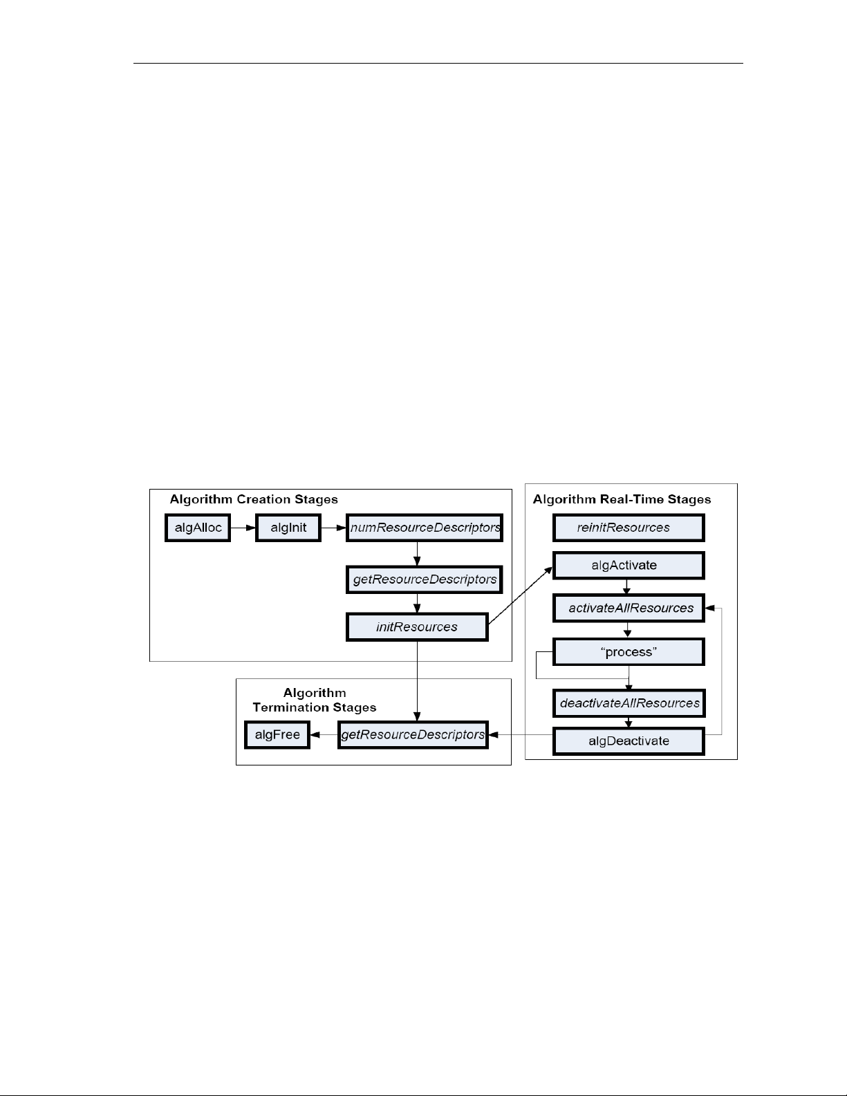
1.1.3 IRES Overview
IRES is a generic, resource-agnostic, extendible resource query, initialization and activation
interface. The application framework defines, implements, and supports concrete resource
interfaces in the form of IRES extensions. Each algorithm implements the generic IRES interface, to
request one or more concrete IRES resources. IRES defines standard interface functions that the
framework uses to query, initialize, activate/deactivate and reallocate concrete IRES resources. To
create an algorithm instance within an application framework, the algorithm and the application
framework agrees on the concrete IRES resource types that are requested. The framework calls
the IRES interface functions, in addition to the IALG functions, to perform IRES resource
initialization, activation, and deactivation.
1-3
Page 16
Introduction
The IRES interface introduces support for a new standard protocol for cooperative preemption, in
addition to the IALG-style non-cooperative sharing of scratch resources. Co-operative preemption
allows activated algorithms to yield to higher priority tasks sharing common scratch resources.
Framework components include the following modules and interfaces to support algorithms
requesting IRES-based resources:
IRES - Standard interface allowing the client application to query and
provide the algorithm with its requested IRES resources.
RMAN - Generic IRES-based resource manager, which manages
and grants concrete IRES resources to algorithms and applications.
RMAN uses a new standard interface, the IRESMAN, to support runtime registration of concrete IRES resource managers.
Client applications call the algorithm’s IRES interface functions to query its concrete IRES resource
requirements. If the requested IRES resource type matches a concrete IRES resource interface
supported by the application framework, and if the resource is available, the client grants the
algorithm logical IRES resource handles representing the allotted resources. Each handle provides
the algorithm with access to the resource as defined by the concrete IRES resource interface.
IRES interface definition and function-calling sequence is depicted in the Figure 1-2. For more
details, see Using IRES and RMAN Framework Components for C64x+ (literature number
SPRAAI5).
Figure 1-2 IRES Interface Definition and Function Calling Sequence
For more details, see Using IRES and RMAN Framework Components for C64x+ (literature number
SPRAAI5).
1.2 Overview of H.264 High Profile Encoder
H.264 is the latest video compression standard from the ITU-T Video Coding Experts Group and
the ISO/IEC Moving Picture Experts Group. H.264 provides greater compression ratios at a very
low bit-rate. The new advancements and greater compression ratios available at a very low bit- rate
has made devices ranging from mobile and consumer electronics to set-top boxes and digital
terrestrial broadcasting to use the H.264 standard.
1-4
Page 17
Introduction
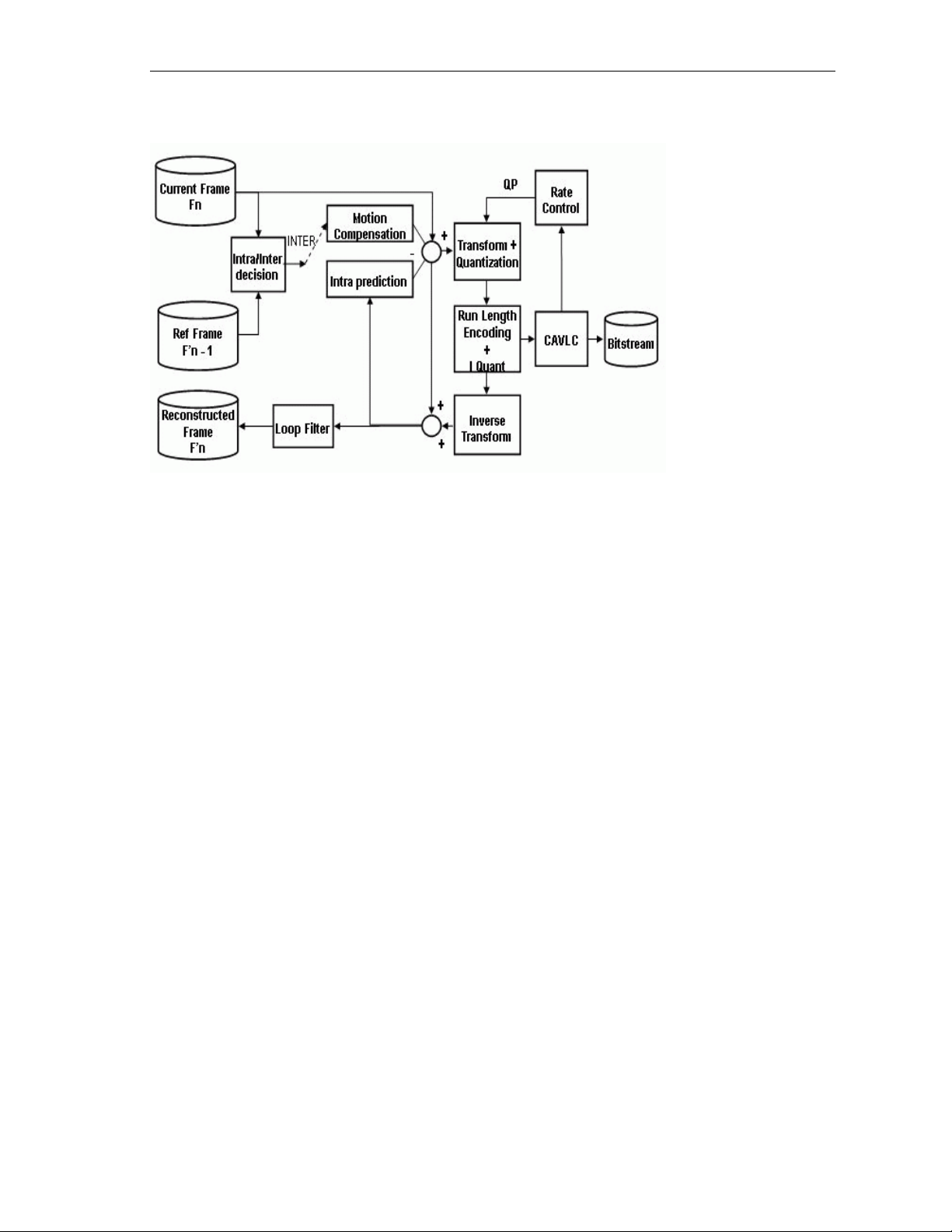
Figure 1-3 depicts the working of the H.264 High Profile Encoder algorithm.
Figure 1-3 Working of H.264 Video Encoder
In H.264 Encoder, the operations are performed on set of specific N macro blocks. The selection of
N depends on the availability of internal memory. The operations such as motion compensation,
transform and quantization, run length encoding and inverse quantization, and inverse transform
blocks are called once for all the inter macro blocks in the set of N.
The encoder is designed such that, it always tries to maximize the throughput of each unit by
allowing it to perform on maximum possible number of macro blocks.
Motion Estimation is the step where encoder searches for the best match in the available reference
frame(s). After quantization, contents of some blocks become zero. The H.264 Encoder keeps track
of this information and passes the information of coded 4x4 blocks to inverse transform so that it
can skip computation for those blocks that contains all zero co-efficients and are not coded.
The H.264 Encoder defines in-loop filtering to avoid blocks across the 4x4 block boundaries. It is
the second most computational task of H.264 encoding process after motion estimation. In-loop
filtering is applied on all 4x4 edges as a post-process and the operations depend upon the edge
strength of the particular edge.
The H.264 Encoder applies entropy coding methods to use context based adaptivity, which in turn
improves the coding performance. All the macro blocks, which belong to a slice, must be encoded
in a raster scan order. Entropy coding methods such has Golomb coding, Context Adaptive
Variable Length Coding (CAVLC) and Context Adaptive Binary Arthmetic Coding (CABAC). Syntax
parameter, which will be used for decoding will be coded in Golomb code. CAVLC is the stage
where transformed and quantized co-efficients are entropy coded using context adaptive table
switching across different symbols. The syntax defined by the H264 Encoder stores the information
at 4x4 block level. CABAC coding depend on context based probability model is selected. Using
State and Most Probable Bit each bits of the syntax elements and residual data are encoded.
1-5
Page 18

Introduction
1.3 Supported Services and Features
This user guide accompanies TI’s implementation of H.264 High Profile Encoder on the
TMS320C6678 platform.
This version of the codec has the following supported features of the standard:
Supports H.264 baseline, main and high profile up to level 4.0
Supports B frame encoding
Supports arbitrary video resolutions from 64x64 upto 4kx4k
Supports image width and height that are multiple of 16, also supports
image width and height being non-multiple of 16
Supports progressive and field based interlace coding with different
controls as ARF(Adaptive Reference Field), MRF(Most Recent Reference
Field), and SPF(Same Parity Reference Field)
Supports control to have Bottom field first for interlaced coding
Supports user controlled partition size till 8x8 block for inter prediction
Supports user controlled all intra modes (16x16, 8x8, and 4x4)
Supports user controllable quantization parameter range, initial
quantization parameter, HRD buffer size
Supports 8x8 and 4x4 transform size
Supports separate Cb and Cr Quantisation parameter control
Supports multiple Scaling Matrix Preset and User Defined Scaling Matrices
Supports user controlled quarter-pel interpolation and integer pel for motion
estimation
Supports in-loop filtering which can be switched off for whole picture as
well for slice boundaries
Supports unrestricted motion vector search which allows motion vectors to
be outside the frame boundary
Supports multiple slices per picture based upon number of macroblocks in
each slice
Controls the balance between encoder speed and quality by using the user
definable encoding preset option
1-6
Supports AIR (Adaptive Intra Refresh) with cyclic intra macro blocks
Supports constrained intra prediction
Supports user controlled all POC types: 0, 1 and 2
Supports user configurable parameters like pic_order_cnt_type,
log2_max_frame_num_minus4, and chroma_qp_index_offset
Page 19

Introduction
Supports insertion of IDR frame at random point with forceFrame control
Supports user controlled IDR frequency control
Supports change of frame rate, and bit rate dynamically
Supports user configurable Group of Pictures (GOP) length and different
GOP structures: Non-Uniform(IBBP) and Uniform(BBIBBP)
Supports byte stream format and NAL unit format.
Support capability to generating only headers
The other explicit features that TI’s H.264 HP Encoder provides are:
eXpressDSP Digital Media (XDM IVIDENC2) interface compliant
Independent of any operating system
Supports only YUV420 planar color sub-sampling format
Supports multi-channel functionality
This version of the codec does not support the following features of the
standard:
Does not support MBAFF/PicAFF
Does not support BASE CLASS only mode
1-7
Page 20

Page 21

2.1 System Requirements
2-2
2.2 Installing the Component
2-2
2.3 Before Building the Algorithm Library and Sample Test
Application
2-9
2.4 Building the Algorithm Library
2-10
2.5 Building Sample Test Application
2-11
2.6 Running Sample Test Application
2-13
2.7 Configuration Files
2-15
2.8 Uninstalling the Component
2-18
Chapter 2
Installation Overview
This chapter provides a brief description on the system requirements and instructions for installing
the codec component. It also provides information on building and running the sample test
application.
Topic Page
2-1
Page 22

Installation Overview
2.1 System Requirements
This section describes the hardware and software requirements for the normal functioning of the
codec component.
2.1.1 Hardware
This codec has been built and tested using Code Composer Studio Version 5.1.0.09000 and sanity
testing is done on Shannon (TMS320C6678) platform.
2.1.2 Software
The following are the software requirements for the normal functioning of the codec:
Development Environment: This project is developed using Code
Composer Studio version 5.1.0.09000. This project is sanity tested on
Shannon (TMS320C6678) platform
Code Generation Tools: This project is compiled, assembled,
archived, and linked using C6000 Code Generation tools version 7.4.1
for C66x CPU.
2.2 Installing the Component
The codec component is released as RTSC package or compressed archive. Following sub
sections details on installation along with directory structure.
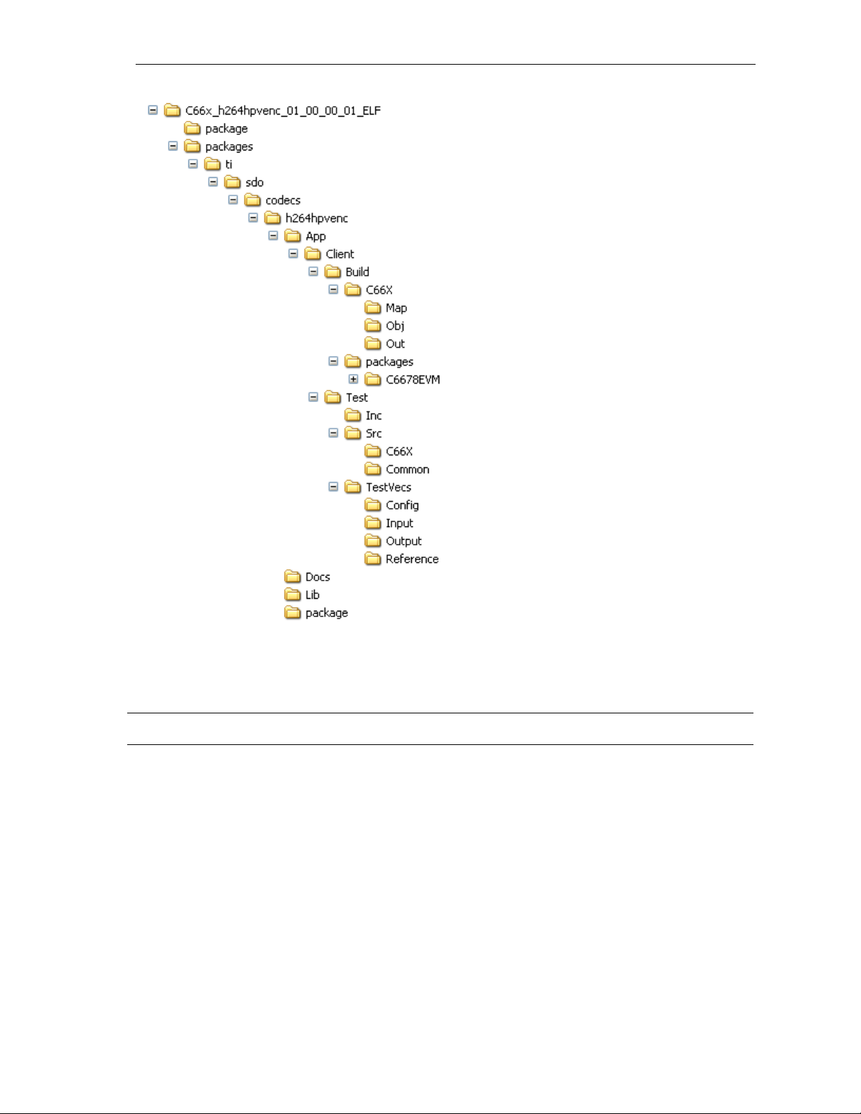
2.2.1 Installing the Component – RTSC Package
The codec component is released as executable. When the excutable is run, a top-level directory
called “C66x_h264hpvenc_01_00_00_00_ELF” created. Figure 2-1 shows sub directorys created
and Table 2-1 provides description of sub directories from the folder “h264hpvenc”.
2-2
Page 23
Installation Overview
Sub-Directory
Description
\h264hpvenc
Contains RTSC package build files along with Sample test application folders,
XDM related codec interface files.
\h264hpvenc\App
Contains sample test application, which uses codec library using IVIDENC2
codec interface.
\h264hpvenc\App\Client\B
uild\C66X\Map
Contains map file generated after building with 66X compiler
\h264hpvenc\App\Client\B
uild\C664X\Obj
Contains intermediate Object files generated after building host test application
with C66X compiler
\h264hpvenc\App\Client\B
uild\C66X\Out
Contains the final application executable (.out) file generated by the sample
test application.
2-3
Figure 2-1 Component Directory Structure In case of RTSC package Release
Table 2-1 Component Directories in case of RTSC package release
Page 24

Installation Overview
Sub-Directory
Description
\h264hpvenc\App\Client\B
uild\packages
Platform RTSC package for building Test application.
\h264hpvenc\App\Client\T
est\Inc
Contains standalone test application header files
\h264hpvenc\App\Client\T
est\Src\C66X
Contains standalone test application source files specific to C66x processor
\h264hpvenc\Client\Test\S
rc\Common
Conatains standalone test application common source files
\h264hpvenc\App\Client
\Test\TestVecs\Config
Contains sample configuration files for H264 High Profile encoder
\h264hpvenc\App\Client
\Test\TestVecs\Input
Contains input test vectors
\h264hpvenc\App\Client
\Test\TestVecs\Output
Contains output generated by the codec. It is empty directory as part of release
\h264hpvenc\App\Client
\Test\TestVecs\Reference
Contains read-only reference output to be used for cross-checking against
codec output
\h264hpvenc\Docs
Contains user guide, data sheet, release notes and software manifest
\h264hpvenc\Lib
Contains the library file named as h264hpvenc_ti.le66 for encoding the
compressed video data
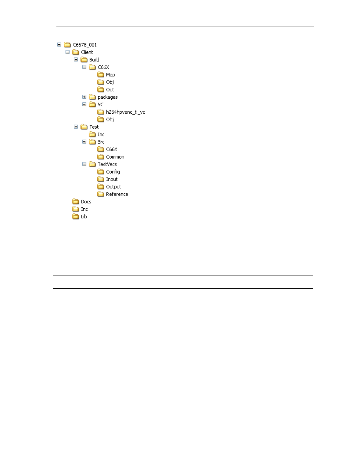
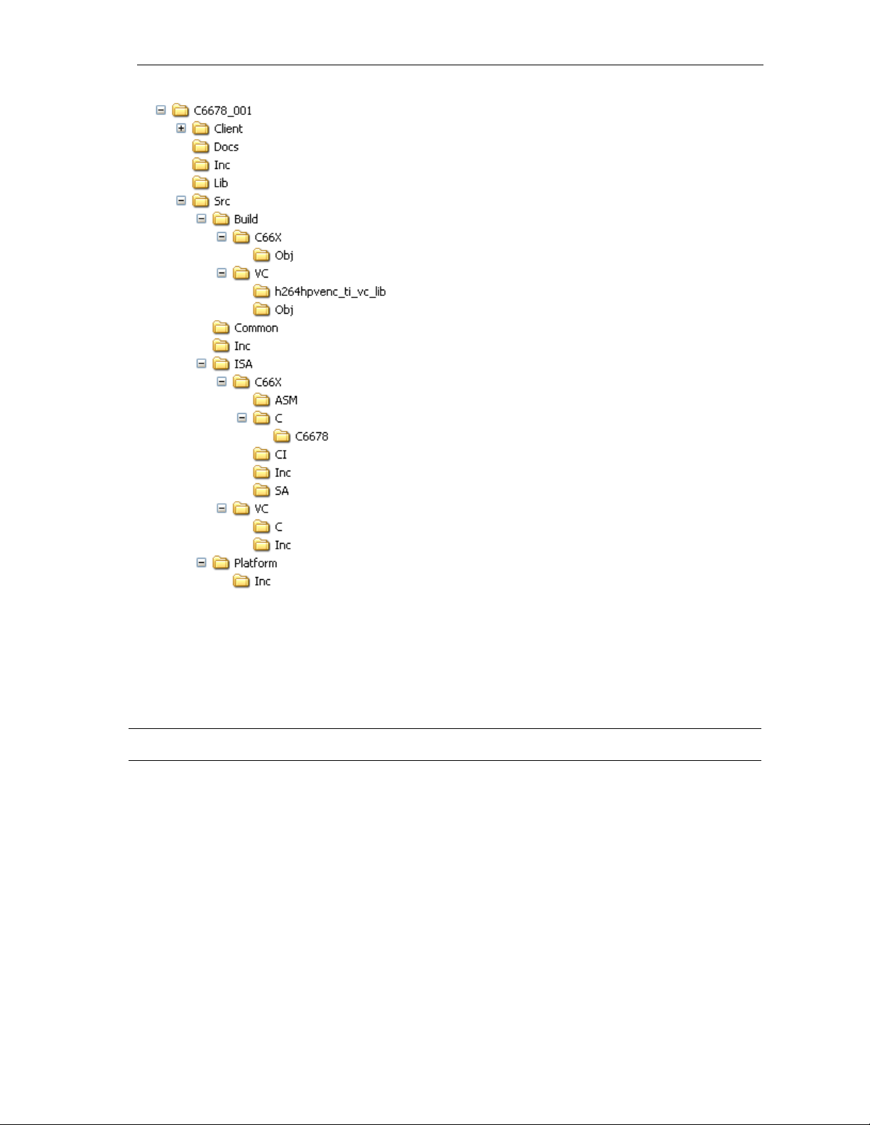
2.2.2 Installing the Component – Compressed archive
The codec component is released as a compressed archive. To install the codec, extract the
contents of the zip file onto your local hard disk. The zip file extraction creates a top-level directory
called 100.V.H264HP.E.C6678.01.00, under which directory named C6678_001 is created.
Figure 2-2 shows the sub-directories created in the C6678_001 directory in case of object release.
Figure 2-3 will show directory structure in case of Source release. Only “Src” is additional in source
release compared to object only release package, remaining folders being same.
C6678_001: This package runs on TMS320C6678 platform.
2-4
Page 25
Installation Overview
Sub-Directory
Description
\Client\Build\C66X\Map
Contains map file generated after building with 66X compiler
\Client\Build\C664X\Obj
Contains intermediate Object files generated after building host test application
with C66X compiler
\Client\Build\C66X\Out
Contains the final application executable (.out) file generated by the sample
test application.
\Client\Build\packages
Platform RTSC package for building Test application.
\Client\Build\VC\h264hpve
nc_ti_vc
Contains project files to build stand alone test application for encoder on VC
\Client\Test\Inc
Contains standalone test application header files
\Client\Test\Src\C66X
Contains standalone test application source files specific to C66x processor
\Client\Test\Src\Common
Conatains standalone test application common source files
Figure 2-2 Component Directory Structure In case of Object Release
Table 2-2 provides a description of the sub-directories created in the C6678_001 directory.
Table 2-2 Component Directories in case of Object release
2-5
Page 26

Installation Overview
Sub-Directory
Description
\Client
\Test\TestVecs\Config
Contains sample configuration files for H264 encoder
\Client
\Test\TestVecs\Input
Contains input test vectors
\Client
\Test\TestVecs\Output
Contains output generated by the codec. It is empty directory as part of release
\Client
\Test\TestVecs\Reference
Contains read-only reference output to be used for cross-checking against
codec output
\docs
Contains user guide, data sheet and release notes
\Inc
Contains XDM related header files, which allow interface to the codec library.
\Lib
Contains the library file named as h264hpvenc_ti_vc.lib,h264hpvenc_ti.le66 for
encoding the compressed video data
2-6
Page 27
Installation Overview
Sub-Directory
Description
\Src\Build\C66X
Contains project files needed to build codec with C66X compiler
\Src\Build\C66X\Obj
Contains intermediate Object files generated after building codec with C66X
compiler
\Src\Build\VC\h264hpvenc
_ti_vc_lib
Contains project files needed to build codec with Microsoft Visual studio
compiler
\Src\Build\VC\Obj
Contains intermediate Object files generated after building codec with C66X
compiler
\Src\Common
Contains common source files needed to build codec
\Src\Inc
Contains common header files needed to build codec
Figure 2-3 Component Directory Structure In case of Source Release
Table 2-3 below provides a description of the additional sub-directories, which are part of source
release package compared to Object release directories (as in Table 2-2)
Table 2-3 Component Directories in case of Source release
2-7
Page 28

Installation Overview
Sub-Directory
Description
\Src\Platform\Inc
Contains Platform specific header files ex. ECPY wrapper APIs
\Src\ISA\C66X\ASM
Contains hand written assembly files specific to C66X processor
\Src\ISA\C66X\C
Contains source files specific to the TMS320C6678 platform
\Src\ISA\C66X\CI
Contains intrinsic implementation of source files for TMS320C6678 platform
\Src\ISA\C66X\Inc
Contains header files of codec specific to TMS320C6678 platform
\Src\ISA\C66X\SA
Contains linear assembly files specific to TMS320C6678 platform
\Src\ISA\VC\C
Contains Visual studio specific C source files for encoder algorithm.
\Src\ISA\VC\Inc
Contains Visual studio specific Include files for encoder algorithm.
2-8
Page 29

Installation Overview
2.3 Before Building the Algorithm Library and Sample Test Application
This codec is accompanied by a sample test application. To run the sample test application, XDAIS
tools, BIOS tools, Framework Components, and XDC tools are required.
This version of the codec has been validated with XDAIS tools containing IVIDENC2 interface
version
The version of the XDAIS tools required is 7.21.01.07
The version of the XDC tools required is 3.22.04.46
The version of the BIOS tools required is 6.32.5.54
The version of the Code Generation tools required is 7.4.1
The version of Framework Components required is 3.23.02.16
The version of EDMA low-level driver required is 2.11.03.03
The version of IPC tools required is 1.23.05.40
Make sure environmental variable “CG_TOOL_ROOT” is set to proper code generation tools
installation path.
2.3.1 Installing XDAIS tools(XDAIS)
XDAIS version 7.21 can be downloaded from the following website:
http://softwaredl.ti.com/dsps/dsps_public_sw/sdo_sb/targetcontent/xdais/7_21_01_07/index_FDS.html
Extract the XDAIS zip file to the same location where Code Composer Studio is installed. For
example:
C:\CCStudio5.0
Set a system environment variable named XDAIS_INSTALL_DIR pointing
to <install directory>\<Xdais_directory>
2.3.2 Installing XDC Tools
XDC Tools are required to build the test application. The test application
uses the standard files like <std.h> from XDC tools. The xdc tools can be
downloaded and installed from the following website:
http://softwaredl.ti.com/dsps/dsps_public_sw/sdo_sb/targetcontent/rtsc/3_22_04_46/index_FDS.html
Also Ensure that the environment variable XDCROOT is set to the XDC installation directory. Eg:set
XDCROOT to <install directory>\<xdc_tools>
Set a system environment variable named XDC_INSTALL_DIR pointing to <install
directory>\<xdc_directory>
2-9
Page 30

Installation Overview
2.3.3 Installing BIOS tools(SYS/BIOS)
Unit test application uses SYS/BIOS tools to create tasks, cache programming
etc. The xdc tools version 6.32.5.54 can be downloaded from the following
website:
http://softwaredl.ti.com/dsps/dsps_public_sw/sdo_sb/targetcontent/bios/sysbios/6_32_05_54
/index_FDS.html
2.3.4 Installing Framework Component(FC)
Framework Components are required for using IRES interface for EDMA3 hardware. FC tools can
be downloaded and installed from the following website
http://software-dl.ti.com/dsps/dsps_public_sw/sdo_sb/targetcontent/fc/3_23_02_16/index_FDS.html
Mare sure that FC tools are recognized as RTSC package in CCS V5 by adding installation
directory path RTSC products search path in CCS V5 preferences.
Set a system environment variable named FC_INSTALL_DIR pointing to <install
directory>\<fc_directory>
2.3.5 Installing EDMA3 Low-Level Driver(LLD)
EDMA3 low-level driver tools are used for configuring EDMA channels and data transfer across
DDR memory to L2 memory using EDMA hardware. EDMA low-level driver can be downloaded
from the following website.
http://software-dl.ti.com/dsps/dsps_public_sw/sdo_tii/psp/edma3_lld/edma3-lldbios6/02_11_03_03/index_FDS.html
Mare sure that EDMA3 LLD tools are recognized as RTSC package in CCS V5 by adding
installation directory path at RTSC products search path in CCS V5 preferences.
2.3.6 Installing Inter Processor Communication (IPC)
Inter processor communication software is used to synchronize multiple cores and share data
between cores via messaging. IPC software version 1.23.5.40 can be downloaded from the
following website
http://softwaredl.ti.com/dsps/dsps_public_sw/sdo_sb/targetcontent/ipc/1_23_05_40/index_FDS.html
2.4 Building the Algorithm Library
Building algorithm library on Visual studio and CCS is specified in section 2.4.1 and 2.4.2
resepctively.
2.4.1 Building Algorithm Library on Visual studio
To build the algorithm library from source code in Visual Studio, follow these steps:
1) Verify that you have installed Microsoft Visual Studio 2008 Express
Edition development environment. Open the source project
2-10
Page 31

Installation Overview
“h264hpvenc_ti_vc_lib.vcproj” from
“..\Src\Build\VC\h264hpvenc_ti_vc_lib\”.
2) This project contains two build configurations “Debug” and “Release”.
“Debug” configuration will disable all the optimizations to debug the
code. “Release” configuration will enable all the optimizations without
exposing symbols. Please select “Debug” configuration.
3) Right click on the above project in Visual Studio IDE and select Build
Project to build the algorithm library.
The built library, h264hpvenc_ti_vc.lib is available in the \Lib sub-directory.
2.4.2 Building Algorithm Library on Code Composer Studio
To build the algorithm library from source code in CCSv5, follow these steps:
1) Select the CCS Edit perspective in the workbench.
2) Add the project named “h264hpvenc_ti_c66x_lib” through “Import
Existing CCS/CCE Eclipse Project” option to the workspace. All files
required for this project are available in the
\C6678_001\Src\Build\C66X\ sub-directory.
3) This project contains three build configurations “Debug”, “Release”
and “Profile”. “Debug” configuration will disable all the optimizations
to debug the code in ELF mode. “Release” configuration will enable
all the optimizations without exposing symbols in ELF mode. Please
select “Release” configuration.
4) Right click on the above project in CCSv5 IDE and select Build
Project to build the algorithm library.
The built library, h264hpvenc_ti.le66 is available in the \Lib sub-directory.
2.5 Building Sample Test Application
Building Sample test application on Visual studio is specified in section 2.5.1. Building Sample test
application on CCS in case of compressed archive and RTSC package is specified in section 2.5.2
and 2.5.3 resepctively.
2.5.1 Building Sample Test Application on Visual Studio
The sample test application that accompanies this codec component will run in Microsoft Visual
Studio 2008 development environment. To build the sample test application in Visual studio 2008
Express edition, follow these steps:
1) Verify that you have installed Microsoft Visual Studio 2008 Express
Edition development environment.
2-11
2) Verify that the following codec object libraries should exist in \Lib sub-
directory
o h264hpvenc_ti_vc.lib: H264 HP Encoder.
3) Start the Visual studio 2008 Express Edition.
Page 32

Installation Overview
4) Select File->Open->Project/Solution and open “h264hpvenc_ti_vc.sln”
located at “..\Client\Build\VC\h264hpvenc_ti_vc\”
5) Select Build->Build solution it builds the stand alone test application
2.5.2 Building the Sample Test Application on Code Composer Studio –
Compressed archive
The sample test application that accompanies this codec component will run on TMS320C6678
Evaluation Module platform. To build the sample test application in Code Composer Studio, follow
these steps:
1) Verify that you have an installation of TI’s Code Composer Studio
version 5.1.0.09000 and code generation tools version 7.4.1 Verify
that the following codec object libraries should exist in C6678_001\Lib
sub-directory
o h264hpvenc_ti.le66: H264 HP Encoder.
2) Make sure all the tools installed and configured as specified in section
2.3.
3) Select the CCS Edit perspective in the workbench.
4) Add the C66X project named “h264hpvenc_ti_c66x” through “Import
Existing CCS/CCE Eclipse Project” option to the workspace. All files
required for this project are available in the
\C6678_001\Client\Build\C66X\ sub-directory
5) This project contains two build configurations “Debug” and “Release”.
“Debug” configuration will disable all the optimizations to debug the
code in ELF mode. “Release” configuration will enable all the
optimizations without exposing symbols in ELF mode. Please select
“Debug” configuration.
6) Open the build properties by right clicking the project, under CCS build
options->Build Variables tab, update“FC_ROOT”, “XDAIS_ROOT”,
”SYSBIOS_ROOT”, “EDMA3LLD_ROOT”, “IPC_ROOT”, variables
with appropriate installation paths.
7) Right click the above projects on CCSv5 IDE and select Rebuild
Project to build all the files present in the project.
8) After successful completion of the build executable
“h264hpvenc_ti_c66x.out” will be present in
“\C6478_001\Client\Build\C6X\Out” sub-directory.
2.5.3 Building the Sample Test Application on Code Composer Studio - RTSC
Package
The sample test application that accompanies this codec component will run on TMS320C6678
Evaluation Module platform. To build the sample test application in Code Composer Studio, follow
these steps:
1) Verify that you have an installation of TI’s Code Composer Studio
version 5.1.0.09000 and code generation tools version 7.4.1 Verify
that the following codec object libraries should exist in
“h264hpvenc\Lib” sub-directory
2-12
Page 33

Installation Overview
o h264hpvenc_ti.le66: H264 HP Encoder.
2) Make sure all the tools installed and configured as specified in section
2.3.
3) Select the CCS Edit perspective in the workbench
4) Add the C66X project named “h264hpvenc_ti_c66x” through “Import
Existing CCS/CCE Eclipse Project” option to the workspace. All files
required for this project are available in the
\h264hpvenc\App\Client\Build\C66X\ sub-directory
5) This project contains two build configurations “Debug” and “Release”.
“Debug” configuration will disable all the optimizations to debug the
code in ELF mode. “Release” configuration will enable all the
optimizations without exposing symbols in ELF mode. Please select
“Debug” configuration.
6) Open the build properties by right clicking the project, under CCS build
options->Build Variables tab, update“FC_ROOT”, “XDAIS_ROOT”,
”SYSBIOS_ROOT”, “EDMA3LLD_ROOT”, “IPC_ROOT”, variables
with appropriate installation paths.
7) Right click on the above project in CCSv5 IDE and select Rebuild
Project to build all the files present in the project.
8) After successful completion of the build executable
“h264hpvenc_ti_c66x.out” will be present in
“\h264hpvenc\App\Client\Build\C66X\Out” sub-directory.
2.6 Running Sample Test Application
Sample test application is used to run codec library in single core or multicore mode. Number of
cores involved can be controlled with “ncores” parameter. Running sample test application on
Visual studio and Code composer studio is specified in section 2.6.1 and section 2.6.2 respectively.
2.6.1 Running the Sample Test Application on Visual Studio
A wrapper function on top of main encode task is written to mimic multicore scenario using multiple
threads. Based on number of cores specified in configuration file, multiple threads are created and
accordingly DDR, SL2, L2 memory is allocated for each thread. To run sample test application
visual studio 2008 follow these steps:
1) Start the Visual studio 2008 Express Edition.
2) Select File->Open->Project/Solution and open “h264hpvenc_ti_vc.sln”
located at “..\Client\Build\VC\h264hpvenc_ti_vc\”
3) Make sure code is built as specified in section 2.5.1.
2-13
4) Set number of cores and cores to be used in “ncores”, “CoreTeamMap”
variables of configuration parameters.
5) Select Debug->Debug solution (F5) to run test application.
6) The sample test application takes the input files stored in the
\Client\Test\TestVecs\Input sub-directory, runs the codec, and uses the
Page 34

Installation Overview
reference files stored in the Client\Test\TestVecs\Reference subdirectory to verify that the codec is functioning as expected.
7) On successful completion, the application displays the following
messages for every display frame:
9) "---Num Frames Encoded : <> Frame Type <> Bits<> ----"
8) The output is written to the file specified (this can then be manually
compared against the reference).
9) On failure, the application exits after encoding the frame in which
codec failed to generate the correct result with printing the error
message from which module it failed.
2.6.2 Running the Sample Test Application on Code Composer Studio
The sample test application that accompanies this codec component will run on TMS320C6678
Evaluation Module platform. To run the sample test application in Code Composer Studio, follow
these steps:
1) Verify that you have an installation of TI’s Code Composer Studio
version 5.1.0.09000 and executable is created in
“..\Client\Build\C66x\Out” folder, after following steps in section 2.5.2 or
2.5.3.
2) Open Code Composer Studio.
3) Open CCS Debug Perspective by clicking on Window->Open
Perspective->other and then by clicking CCS Debug.
4) Make sure TMS320C6678 target is configured with TMS320C6678
EVM by checking View->Target Configurations-> user Defined. One
should see the specific target; if it is not available go to Target->New
Target Configuration. Give name of the target, next select
TMS320C6678 Device according to the type of JTAG availability.
5) Set number of cores and cores to be used in “ncores”, “CoreTeamMap”
variables of configuration parameters based on usecase.
6) Select each C66x device and do Run->Connect Target to connect to
the C66x core of EVM. Once connected, do Run->Reset->System
Reset.
7) For connected cores do Run->Load->Load Program, browse to
the”..\Client\Build\C66X\Out\” sub-directory, select the codec
executable “h264hpvenc_ti_c66x.out” and load it for execution.
8) After loading executable on all the specified cores do Run->Resume
to start encoding.
9) The sample test application takes the input files stored in the
\Client\Test\TestVecs\Input sub-directory, runs the codec, and uses the
reference files stored in the Client\Test\TestVecs\Reference subdirectory to verify that the codec is functioning as expected.
2-14
10) On successful completion, the application displays the following
messages for every display frame:
Page 35

Installation Overview
# <ParameterName> = <ParameterValue> # Comment
##################################################################################
# Files
##################################################################################
InputFile = ..\..\..\Test\TestVecs\Input\airshow_p352x288.yuv
EncodedFile= ..\..\..\Test\TestVecs\Output\airshow_p352x288.264
ReferenceFile = ..\..\..\Test\TestVecs\Reference\airshow_p352x288_ref.264
##################################################################################
# Multicore Parameters
##################################################################################
ncores = 8
CoreTeamMap = 0,1,2,3,4,5,6,7
##################################################################################
# Encoder Control
##################################################################################
EncodingPreset = 3 # encoding preset 0: Default, 1: High_Quality,
2: High_Speed, 3: User Defined
RateControlPreset = 5 # 5: IVIDEO_USER_DEFINED, 4: IVIDEO_NONE, 2:
Note:
Reference file specified in “Reference” folder can be used
only for comparing eight-core output.
10) "---Num Frames Encoded :<> Frame Type <> Bits<>Padding
Bits<>---"
11) On failure, the application exits after decoding the frame in which
codec failed to generate the correct result with printing the error
message from which module it failed.
11)
2.7 Configuration Files
This codec is shipped along with:
Encoder configuration file (encoder.cfg) – specifies the configuration
parameters used by the test application to configure the Encoder.
TestCases.txt – This file has list of config files, these needs to be executed
with parameter (integer) preceding. The meaning of the parameter is
below.
0 – execute the test case
1 – Skip the test case.
2 – Terminate the regression
2.7.1 Encoder Configuration File
The encoder configuration file, encoder.cfg contains the configuration parameters required for the
encoder. The Encoder.cfg file is available in the \Client\Test\TestVecs\Config sub-directory. A
sample encoder.cfg file is as shown.
2-15
Page 36

Installation Overview
IVIDEO_STORAGE, 1: IVIDEO_LOW_DELAY
framesToEncode = 300 # Total number of frames to encode
MaxWidth = 640 # Max Frame width
MaxHeight = 480 # Max Frame height
MaxInterFrameInterval= 3 # I to P frame distance
InputChromaFormat = 1 # 1 => XDM_YUV_420P, Only 1 is supported.
InputContentType = 0 # Input buffer content type, 0 -> Progressive Type, 1->
Interlaced.
Profile = 100 # Encoding profile 100 => HP, 77 => MP, 66 => BP
Level = 40 # Level IDC (e.g. 20 = level 2.0)
inputWidth = 352 # width of image
inputHeight = 288 # Height of image
targetFrameRate = 30000 # Target frame rate in fps * 1000
targetBitRate = 1000000 # Target Bit Rate in Bits per second.
intraFrameInterval = 15 # Interval between two consecutive intra frames
interFrameInterval = 3 # M: Number of (M-1) B frames between two ref. frames.
mvAccuracy = 2 # 0 => integer pel 2=> quarter pel
generateHeader = 0 # 1: Encode only header, 0: Encode entire access unit,
including the headers
forceFrame = -1 # -1: IVIDEO_NA_FRAME, 3: IVIDEO_IDR_FRAME
dataLayout = 0 # input data buffer layout 0=> interleaved, 1=> seprated.
sampleAspectRatioHeight = 1 # Aspect Ratio Height
sampleAspectRatioWidth = 1 # Aspect Ratio Width
##################################################################################
# Rate Control Params
##################################################################################
rateControlParamsPreset = 1 # 0: default, 1: user defined
rcAlgo = 0 # 0: Variable Bitrate, 1 : Constant bitrate.
qpI = -1 # Initial QP for I/IDR frames, -1: codec chosen
qpP = -1 # Initial QP for P frames
qpOffsetB = 4 # Offset of B frames QP from P frames
qpMaxI = 51 # Maximum QP for I/IDR frames
qpMinI = 1 # Minimum QP for I/IDR frames
qpMaxP = 51 # Maximum QP for P frames
qpMinP = 1 # Minimum QP for P frames
qpMaxB = 51 # Maximum QP for B frames
qpMinB = 1 # Minimum QP for B frames
CbQPIndexOffset = 0 # Specifies offset to be added to luma QP for
addressing QPC values table for chroma component Cb
CrQPIndexOffset = 0 # Specifies offset to be added to luma QP for
addressing QPC values table for chroma component Cr
initialBufferLevel = 26214400 # Initial Buffer level for HRD compliance
HRDBufferSize = 26214400 # HRD Buffer Size in bits - 2*bitrate for VBR
enablePRC = 1 # 0 => Disable, Non-Zero => Enable
frameSkipAfterSceneChange = 1 # 0=> no forced skip after scenechange, 1=>force
skip frame after coding scene change frame.
##################################################################################
# InterCoding Control
##################################################################################
interCodingPreset = 1 # 0 => deafult values, 1 => user defined
MvRangeVerP = 32 #Vertical MV Range for P frames in integer pixels (16 to 496)
MvRangeHorP = 144# Horizontal MV Range for P frames in integer pixels(16to496)
MvRangeVerB = 32# Vertical MV Range for B frames in integer pixels (16 to 496)
MvRangeHorB = 144# Horizontal MV Range for P frames in integer pixels(16to496)
maxMVperMB = 1 # Maximum MV per MB (Values of 1 & 4 are valid)
##################################################################################
# IntraCoding Control
2-16
Page 37

Installation Overview
##################################################################################
intraCodingPreset = 1 # 0 => deafult values, 1 => user defined
enableIntraPartition = 4 # 0 => INTRA_PARTITION_NONE , 1 =>
INTRA_PARTITION_ISLICES, 2 =>
INTRA_PARTITION_IPSLICES, 3 =>
INTRA_PARTITION_IBSLICES, 4 =>
INTRA_PARTITION_IPBSLICES
intraRefreshMethod = 0 # IH264_INTRAREFRESH_NONE = 0,
IH264_INTRAREFRESH_CYCLIC_MBS = 1
intraRefreshRate = 0 # Rate at which intra MB Refresh is done.
constrainedIntraPredEnable = 0 # Controls the intra MB coding in inter slices
##################################################################################
# Entropy Coding Mode
##################################################################################
entropyCodingMode = 1 # Enropy coding type, (0 => CAVLC, 1 => CABAC)
##################################################################################
# Slice Mode Configuration
##################################################################################
sliceCodingPreset = 0 # 0 => deafult values, 1 => user defined
streamFormat = 0 # format (0 =>Byte stream format, 1 => NALU stream format)
sliceMode = 0 # Type of slice coding, (0 => frame based, 1 => Slices are
controlled based upon number of Macroblocks
sliceUnitSize = 0 # Number of macroblocks per slice
##################################################################################
# Loop Filter Control
##################################################################################
loopfilterPreset = 1 # 0 => deafult values, 1 => user defined
loopfilterDisableIDC = 2 # (0=Filter, 1= NoFilter, 2 = No filter across slices)
filterOffsetA = 0 # Alpha offset for loop filter
filterOffsetB = 0 # Beta offset for loop filter
##################################################################################
# VUI Control Params
##################################################################################
vuiCodingPreset = 0 # 0 => deafult values, 1 => user defined
aspectRatioInfoPresentFlag = 1 # Controls the insertion of aspect ratio
information in VUI part of bit-stream
aspectRatioIdc = 1 # Aspect ratio ID
videoSignalTypePresentFlag = 0 # insertion of video signal type in VUI part of
bit-stream
videoFormat = 2 # Video signal type
videoFullRangeFlag = 0 # Flag to specigy Range of the pixels
colourDescriptionPresentFlag = 1 # Specifies whether colour_primaries,
transfer_characteristics and
matrix_coefficients are present or not.
colourPrimaries = 5 # Indicates the chromaticity coordinates of the
source primaries(Table E-3 in standard)
transferCharacteristics = 5 # Indicates the opto-electronic transfer
characteristic of the source picture(Table E-4 in
standard)
matrixCoefficients = 5 # Describes the matrix coefficients used in deriving
luma and chroma signals from the green, blue,and
red primaries(Table E-5 in standard)
timingInfoPresentFlag = 1 # Controls the insertion of timing info related
parameters in VUI part of bit-stream
##################################################################################
# MISC
2-17
Page 38

Installation Overview
##################################################################################
gopStructure = 0 # 0 => Open or Non uniform(IBBPBBP), 1 => Closed or
Uniform (BBIBBPBB
log2MaxFNumMinus4 = 0 # # sliceParams::frame_num syntax element will be reset
after every (1<< (log2MaxFNumMinus4 + 4)) frames
picOrderCountType = 0 # Picture order count type
IDRFrameInterval = 1000 # Interval b/w two IDR frames 0=>IDR BBP I BBP I,
1=>IDR BBP IDR BBP IDR, 2=>IDR BBP I BBP IDR,
3=>IDR BBP I BBP I BBP IDR
transformBlockSize = 1 # 0:4x4 only, 1: 8x8 only,
topFieldFirstFlag = 1 # to indicate field order in interlaced content
interlaceCodingType = 3 # Interlced field coding type selection, 2 => MRF 3=> ARF
4=> SPF
DebugTraceLevel = 0 # Debug trace Enable 0 - Disable, 1- Level 1, 2 - Level
2, 3 - Level 3,
lastNFramesToLog = 5 # Last N frames to log into debug trace buffer
Any field in the IVIDENC2_Params structure (see Section 4.2.1.7) can be set in the encoder.cfg file
using the syntax as shown in the code snippet. If you specify additional fields in the encoder.cfg file,
ensure that you modify the test application appropriately to handle these fields.
2.8 Uninstalling the Component
To uninstall the component, delete the codec directory from your hard disk.
2-18
Page 39

3.1 Overview of the Test Application
3-2
3.2 Frame Buffer Management
3-5
Chapter 3
Sample Usage
This chapter provides a detailed description of the sample test application that accompanies this
codec component.
Topic Page
3-1
Page 40

Sample Usage
3.1 Overview of the Test Application
The test application exercises the IVIDENC2 and extended class of the H.264 High Profile Encoder
library. The source files for this application are available in the \Client\Test\Src and \Client\Test\Inc
sub-directories.
Figure 3-1 Test Application Sample Implementation
The test application is divided into four logical blocks:
Parameter setup
Algorithm instance creation and initialization
Process call
Algorithm instance deletion
3-2
Page 41

Sample Usage
3.1.1 Parameter Setup
Each codec component requires various codec configuration parameters to be set at initialization.
For example, a video codec requires parameters such as video height, video width, and so on. The
test application obtains the required parameters from the Encoder configuration files.
In this logical block, the test application does the following:
1) Opens the configuration file, listed in TesCases.txt and reads the
2) various configuration parameters required for the algorithm.
For more details on the configuration files, see Section 2.5.
3) Sets the interface structure based on the values it reads from the
configuration file.
4) Does the algorithm instance creation and other handshake via. control
methods
5) For each frame reads the input yuv frame into the application input
buffer and makes a process call
6) For each frame dumps out the generated bit-stream into the specified
file
3.1.2 Algorithm Instance Creation and Initialization
In this logical block, the test application accepts the various initialization parameters and returns an
algorithm instance pointer. The following APIs implemented by the codec are called in sequence by
ALG_create():
1) algNumAlloc() - To query the algorithm about the number of memory
records it requires.
2) algAlloc() - To query the algorithm about the memory requirement
to be filled in the memory records.
3) algInit() - To initialize the algorithm with the memory structures
provided by the application.
A sample implementation of the create function that calls algNumAlloc(), algAlloc(), and
algInit() in sequence is provided in the ALG_create() function implemented in the alg_create.c
file.
After successful creation of the algorithm instance, the test application does resource allocation for
the algorithm. This requires initialization of Resource Manager Module (RMAN) and grant of
required resources (EDMA channels). This is implemented by calling RMAN interface functions in
following sequence:
1) numResourceDescriptors() - To understand the number of
resources needed by algorithm.
2) getResourceDescriptors() – To get the attributes of the resources.
initResources() - After resources are created, application gives the resources to algorithm
through this API
3-3
Page 42

Sample Usage
3.1.3 Process Call
After algorithm instance creation and initialization, the test application does the following:
3) Sets the dynamic parameters (if they change during run-time) by
calling the control() function with the XDM_SETPARAMS command.
4) Sets the input and output buffer descriptors required for the
process() function call. The input and output buffer descriptors are
obtained by calling the control() function with the XDM_GETBUFINFO
command.
5) Calls the process() function to encode/decode a single frame of data.
The behavior of the algorithm can be controlled using various dynamic
parameters (see Section 4.2.1.8). The inputs to the process function
are input and output buffer descriptors, pointer to the
IVIDENC2_InArgs and IVIDENC2_OutArgs structures.
6) When the process() function is called for encoding/decoding a single
frame of data, the software triggers the start of encode/decode. After
triggering the start of the encode/decode frame, the video task can be
placed in SEM-pend state using semaphores. On receipt of interrupt
signal at the end of frame encode/decode, the application releases the
semaphore and resume the video task, which does any book-keeping
operations by the codec and updates the output parameters.
The control() and process() functions should be called only within the scope of the
algActivate() and algDeactivate() XDAIS functions, which activate and deactivate the
algorithm instance respectively. If the same algorithm is in-use between two process/control
function calls, calling these functions can be avoided. Once an algorithm is activated, there can be
any ordering of control() and process() functions. The following APIs are called in sequence:
1) algActivate() - To activate the algorithm instance.
2) control() (optional) - To query the algorithm on status or setting of
dynamic parameters and so on, using the eight control commands.
3) process() - To call the Encoder with appropriate input/output buffer
and arguments information.
4) control() (optional) - To query the algorithm on status or setting of
dynamic parameters and so on, using the eight available control
commands.
5) algDeactivate() - To deactivate the algorithm instance.
The do-while loop encapsulates frame level process() call and updates the input buffer pointer
every time before the next call. The do-while loop breaks off either when an error condition occurs
or when the input buffer exhausts.
If the algorithm uses any resources through RMAN, then user must activate the resource after the
algorithm is activated and deactivate the resource before algorithm deactivation.
3-4
Page 43

Sample Usage
Frame Type
I P P P P
Input ID
1 2 3 4 5
Free Buffer ID
1 2 3 4 5
Frame Type
I B B P B B P
Input ID
1 2 3 4 5 6 7
Free Buffer ID
0 0 1 4 2 3 7
3.1.4 Algorithm Instance Deletion
Once decoding/encoding is complete, the test application must release the resources granted by
the IRES resource Manager interface and delete the current algorithm instance. The following APIs
are called in sequence:
1) Free all resources granted by RMAN
2) algNumAlloc() - To query the algorithm about the number of memory
records it used.
3) algFree() - To query the algorithm to get the memory record
information.
A sample implementation of the delete function that calls algNumAlloc() and algFree() in
sequence is provided in the ALG_delete() function implemented in the alg_create.c file.
After successful execution of the algorithm, the test application frees up the DMA Resource
allocated for the algorithm. This is implemented by calling the RMAN interface functions in the
following sequence:
4) RMAN_freeResources () - To free the resources that were allocated
to the algorithm before process call.
5) RMAN_exit() - To delete the generic IRES RMAN and
release memory.
3.2 Frame Buffer Management
3.2.1 Input Frame Buffer
The encoder has input buffers that stores frames until they are processed. These buffers at the
input level are associated with a buffer input IDs. The IDs are required to track the buffers that
have been processed or locked. The encoder uses this ID, at the end of the process call, to inform
back to application whether it is a free buffer or not. Any buffer given to the algorithm should be
considered locked by the algorithm, unless the buffer is returned to the application through
IVIDENC2_OutArgs->freeBufID[].For more information, see section 4.2.1.11.
For example, consider the GOP structure for IPPPP frames.
As shown in the table, if the input ID for the first frame is 1, the same input ID is returned as the free
buffer ID at the end of the process call. There is no locking of buffers at any point.
Now, consider the GOP structure that has B frames, IBBPBBP.
3-5
Page 44

Sample Usage
As shown in the table, the first frame input ID (1) is returned as a free buffer ID at the end of the
third process call that is after accumulating buffers for two B frames. For the first two process calls,
free buffer IDs are returned as zero. This initial delay is equal to the number of B frames.
Since the 4th frame is a P frame, it is returned immediately at the end of the process call. Then,
input IDs, 2 and 3 are returned as free buffers while frames 5 and 6 are being processed. Hence, if
there are two B frames between P frames, the input images for the B frames are stored and the P
frame is encoded first, and then the two B frames are encoded. This results in two frame period
initial delay.
3-6
Page 45

4.1 Symbolic Constants and Enumerated Data Types
4-2
4.2 Data Structures
4-28
4.3 Default and Supported Values of Parameters
4-64
4.4 Interface Functions
4-74
Chapter 4
API Reference
This chapter provides a detailed description of the data structures and interfaces functions used in
the codec component.
Topic Page
4-1
Page 46

API Reference
Group or Enumeration
Class
Symbolic Constant
Name
Description or Evaluation
IVIDEO_FrameType
For the various IVIDEO_xy_FRAME values, this frame
type is interlaced where both top and bottom fields
are provided in a single frame. The first field is
an x frame, the second field is y field.
IVIDEO_NA_FRAME
Frame type not available
IVIDEO_I_FRAME
IVIDEO_FRAMETYPE_D
EFAULT
Intra coded frame,
Default value.
IVIDEO_P_FRAME
Forward inter coded frame.
IVIDEO_B_FRAME
Bi-directional inter coded frame.
IVIDEO_IDR_FRAME
Intra coded frame that can be used for
refreshing video content.
IVIDEO_II_FRAME
Interlaced frame, both fields are I
frames.
IVIDEO_IP_FRAME
Interlaced frame, first field is an I frame,
second field is a P frame.
IVIDEO_IB_FRAME
Interlaced frame, first field is an I frame,
second field is a B frame.
IVIDEO_PI_FRAME
Interlaced frame, first field is a P frame,
second field is a I frame.
IVIDEO_PP_FRAME
Interlaced frame, both fields are P
frames.
IVIDEO_PB_FRAME
Interlaced frame, first field is a P frame;
second field is a B frame.
IVIDEO_BI_FRAME
Interlaced frame, first field is a B frame,
second field is an I frame.
IVIDEO_BP_FRAME
Interlaced frame, first field is a B frame,
second field is a P frame.
4.1 Symbolic Constants and Enumerated Data Types
This section summarizes all the symbolic constants specified as either #define macros and/or
enumerated C data types. For each symbolic constant, the semantics or interpretation of the same
is also provided.
4.1.1 Common XDM Data types
This section includes common XDM Enumerated data types:
Table 4-1 List of Enumerated Data Types
4-2
Page 47

Group or Enumeration
Class
Symbolic Constant
Name
Description or Evaluation
IVIDEO_BB_FRAME
Interlaced frame, both fields are B
frames.
IVIDEO_MBAFF_I_FRA
ME
Intra coded MBAFF frame.
IVIDEO_MBAFF_P_FRA
ME
Forward inter coded MBAFF frame.
IVIDEO_MBAFF_B_FRA
ME
Bi-directional inter coded MBAFF
frame.
IVIDEO_MBAFF_IDR_F
RAME
Intra coded MBAFF frame that can be
used for refreshing video content.
IVIDENC2_Control
Process based Controls operation for Video encoder
IVIDENC2_CTRL_NONE
IVIDENC2_CTRL_DEFA
ULT
No special control operation
IVIDENC2_CTRL_FORC
ESKIP
Force frame to be skipped.
The encoder should ignore this
operation if the frame for which the
control is issued is IDR/I frame.
IVIDEO_MetadataType
IVIDEO_METADATAPLA
NE_NONE
Used to indicate no metadata is
requested or available
IVIDEO_METADATAPLA
NE_MBINFO
Used to indicate that MB info metadata
is requested or available
IVIDEO_METADATAPLA
NE_EINFO
Used to indicate that Error info
metadata is requested or available
IVIDEO_METADATAPLA
NE_ALPHA
Used to indicate that Alpha metadata is
requested or available
IVIDEO_ContentType
IVIDEO_CONTENTTYPE
_NA
Frame type is not available.
IVIDEO_PROGRESSIVE
IVIDEO_PROGRESSIVE
_FRAME
IVIDEO_CONTENTTYPE
_DEFAULT
Progressive video content.
Default value is
IVIDEO_PROGRESSIVE
IVIDEO_INTERLACED
IVIDEO_INTERLACED_
FRAME
Interlaced video content.
IVIDEO_INTERLACED_
TOPFIELD
Interlaced video content, top field.
4-3
Page 48

API Reference
Group or Enumeration
Class
Symbolic Constant
Name
Description or Evaluation
IVIDEO_INTERLACED_
BOTTOMFIELD
Interlaced video content, bottom field.
IVIDEO_RateControlPr
eset
IVIDEO_LOW_DELAY
Constant Bit Rate (CBR) control for
video conferencing.
IVIDEO_STORAGE
IVIDEO_RATE_CONTRO
L_PRESET_DEFAULT
Variable Bit Rate (VBR) control for local
storage (DVD) recording,
Default rate control preset value.
IVIDEO_TWOPASS
Two pass rate control for non-real time
applications.
IVIDEO_NONE
No configurable video rate control
mechanism.
IVIDEO_USER_DEFINE
D
User defined configuration using
extended parameters.
IVIDEO_SkipMode
IVIDEO_FRAME_ENCOD
ED
IVIDEO_SKIPMODE_DE
FAULT
Input video frame successfully
encoded.
Default skip mode.
IVIDEO_FRAME_SKIPP
ED
Input video frame skipped. There is no
encoded bit-stream corresponding to
the input frame.
IVIDEO_OutputFrameSt
atus
IVIDEO_FRAME_NOERR
OR
IVIDEO_OUTPUTFRAME
STATUS_DEFAULT
Output buffer is available (default
value).
Default status of the output frame.
IVIDEO_FRAME_NOTAV
AILABLE
Encoder does not have any output
buffers.
IVIDEO_FRAME_ERROR
Output buffer is available and
corrupted.
For example, if a bit-stream is
erroneous and partially decoded, a
portion of the decoded image may be
available for display.
Another example is if the bit-stream for
a given frame decode may be decoded
without error, but the previously
decoded dependant frames were not
successfully decoded. This would result
in an incorrectly decoded frame.
Not applicable for encoders.
IVIDEO_PictureType
IVIDEO_NA_PICTURE
Frame type not available
IVIDEO_I_PICTURE
IVIDEO_PICTURE_TYP
E_DEFAULT
Intra coded picture.
Default value.
4-4
Page 49

Group or Enumeration
Class
Symbolic Constant
Name
Description or Evaluation
IVIDEO_P_PICTURE
Forward inter coded picture.
IVIDEO_B_PICTURE
Bi-directional inter coded picture.
IVIDEO_VideoLayout
IVIDEO_FIELD_INTER
LEAVED
Buffer layout is interleaved.
IVIDEO_FIELD_SEPAR
ATED
Buffer layout is field separated.
IVIDEO_TOP_ONLY
Buffer contains only top field.
IVIDEO_BOTTOM_ONLY
Buffer contains only bottom field.
IVIDEO_OperatingMode
IVIDEO_DECODE_ONLY
Decoding mode.
Not applicable for encoders.
IVIDEO_ENCODE_ONLY
Encoding mode.
IVIDEO_TRANSCODE_F
RAMELEVEL
Transcode mode of operation
(encode/decode) that
consumes/generates transcode
information at the frame
level.
IVIDEO_TRANSCODE_M
BLEVEL
Transcode mode of operation
(encode/decode) that
consumes/generates transcode
information at the MB level.
IVIDEO_TRANSRATE_F
RAMELEVEL
Transrate mode of operation
for encoder that consumes
transrate information at the
frame level.
IVIDEO_TRANSRATE_M
BLEVEL
Transrate mode of operation for
encoder, which consumes transrate
information at the MB level.
Not supported in this version of H264
Encoder.
IVIDEO_BitRange
IVIDEO_YUVRANGE_FU
LL
Pixel range for YUV is 0-255.
IVIDEO_YUVRANGE_IT
U
Pixel range for YUV is as per ITU-T .
IVIDEO_DataMode
IVIDEO_FIXEDLENGTH
Data is exchanged at interval of fixed
size.
IVIDEO_SLICEMODE
Slice mode.
IVIDEO_NUMROWS
Number of rows, each row is 16 lines of
video.
IVIDEO_ENTIREFRAME
Processing of entire frame data.
4-5
Page 50

API Reference
Group or Enumeration
Class
Symbolic Constant
Name
Description or Evaluation
XDM_AccessMode
XDM_ACCESSMODE_REA
D
Algorithm read from the buffer using the
CPU.
XDM_ACCESSMODE_WRI
TE
Algorithm writes to the buffer using the
CPU.
XDM_CmdId
XDM_GETSTATUS
Query algorithm instance to fill Status
structure.
XDM_SETPARAMS
Set run-time dynamic parameters
through the DynamicParams
structure.
XDM_RESET
Reset the algorithm. All fields in the
internal data structures are reset and all
internal buffers are flushed.
XDM_SETDEFAULT
Restore the algorithm's internal state to
its original, default values.
The application needs to initialize the
dynamicParams.size and
status.size fields prior to calling
control() with XDM_SETDEFAULT.
The algorithm must write to the
status.extendedError field, and
potentially algorithm specific, extended
fields.
XDM_SETDEFAULT differs from
XDM_RESET. In addition to restoring
the algorithm's internal state,
XDM_RESET also resets any channel
related state.
XDM_FLUSH
Handle end of stream conditions.
This command forces the algorithm to
output data without additional input.
The recommended sequence is to call
the control() function (with
XDM_FLUSH) followed by repeated
calls to the process() function until it
returns an error.
The algorithm should return the
appropriate, class-specific EFAIL error
(example, ISPHDEC1_EFAIL,
IVIDENC1_EFAIL, and so on), when
flushing is complete.
4-6
Page 51

Group or Enumeration
Class
Symbolic Constant
Name
Description or Evaluation
XDM_GETBUFINFO
Query algorithm instance regarding its
properties of input and output buffers.
The application only needs
to initialize the
dynamicParams.size, the
status.size, and set any buffer
descriptor fields (example,
status.data) to NULL prior to
calling control() with
XDM_GETBUFINFO.
XDM_GETVERSION
Query the algorithm's version.
The result is returned in the data field of
the respective _Status structure.
There is no specific format defined for
version returned by the algorithm.
The memory is not allocated by
encoder and needs to be allocated by
user. The buffer requirement for
holding version number is of length
IH264HPVENC_VERSION_LENGTH
XDM_GETCONTEXTINFO
Query a split codec part for its context
needs. Only split codecs are required to
implement this command.
Not supported in this version of H264
Encoder.
XDM_GETDYNPARAMSDE
FAULT
Query the algorithm to fill the default
values for the parameters, which can
be configured dynamically.
To get the current value of an algorithm
instance's dynamic parameters, it is
recommended that the algorithm
provides them through the
XDM_GETSTATUS call.
XDM_SETLATEACQUIRE
ARG
Set an algorithm's 'late acquire'
argument. Only algorithms that utilize
the late acquire IRES feature may
implement this command.
XDM_DataFormat
XDM_BYTE
Big endian stream (default value)
XDM_LE_16
16-bit little endian stream.
XDM_LE_32
32-bit little endian stream.
XDM_LE_64
64-bit little endian stream.
XDM_BE_16
16-bit big endian stream.
XDM_BE_32
32-bit big endian stream.
XDM_BE_64
64-bit big endian stream.
4-7
Page 52

API Reference
Group or Enumeration
Class
Symbolic Constant
Name
Description or Evaluation
XDM_ChromaFormat
XDM_CHROMA_NA
Chroma format not applicable.
XDM_YUV_420P
YUV 4:2:0 planar.
XDM_YUV_422P
YUV 4:2:2 planar.
XDM_YUV_422IBE
YUV 4:2:2 interleaved (big endian).
XDM_YUV_422ILE
YUV 4:2:2 interleaved (little endian)
XDM_YUV_444P
YUV 4:4:4 planar.
XDM_YUV_411P
YUV 4:1:1 planar.
XDM_GRAY
Gray format.
XDM_RGB
RGB color format.
XDM_YUV_420SP
YUV 4:2:0 chroma semi-planar format
(first plane is luma and second plane is
CbCr interleaved)
Default value.
XDM_ARGB8888
Alpha plane color format.
XDM_RGB555
RGB555 color format.
XDM_RGB565
RGB565 color format.
XDM_YUV_444ILE
YUV 4:4:4 interleaved (little endian)
color format.
XDM_MemoryType
XDM_MEMTYPE_ROW
XDM_MEMTYPE_RAW
Raw memory type.
XDM_MEMTYPE_TILED8
2D memory in 8-bit container of tiled
memory space.
XDM_MEMTYPE_TILED1
6
2D memory in 16-bit container of tiled
memory space.
XDM_MEMTYPE_TILED3
2
2D memory in 32-bit container of tiled
memory space.
XDM_MEMTYPE_TILEDP
AGE
2D memory in page container of tiled
memory space.
XDM_MemoryUsageMode
XDM_MEMUSAGE_DATAS
YNC
Bit-mask to indicate the usage mode.
Bit-0 is Data Sync mode. If this bit is set
then it means that buffer is used in data
sync mode
XDM_EncodingPreset
XDM_DEFAULT
Default setting of the algorithm specific
creation time parameters.
4-8
Page 53

Group or Enumeration
Class
Symbolic Constant
Name
Description or Evaluation
XDM_HIGH_QUALITY
Set algorithm specific creation time
parameters for high quality.
XDM_HIGH_SPEED
Set algorithm specific creation time
parameters for high speed.
XDM_USER_DEFINED
XDM_PRESET_DEFAULT
User defined configuration using
advanced parameters.
Default value.
XDM_HIGH_SPEED_MED
_QUALITY
Set algorithm specific creation time
parameters for high speed medium
quality.
XDM_MED_SPEED_MED_
QUALITY
Set algorithm specific creation time
parameters for medium speed medium
quality.
XDM_MED_SPEED_HIGH
_QUALITY
Set algorithm specific creation time
parameters for medium speed high
quality.
XDM_EncMode
XDM_ENCODE_AU
Encode entire access unit, including the
headers.
Default value.
XDM_GENERATE_HEADE
R
Encode only header
IVIDENC2_MotionVecto
rAccuracy
IVIDENC2_MOTIONVEC
TOR_PIXEL
Motion vectors accuracy is only integer
pel.
IVIDENC2_MOTIONVEC
TOR_HALFPEL
Motion vectors accuracy is half pel.
IVIDENC2_MOTIONVEC
TOR_QUARTERPEL
Motion vectors accuracy is quarter pel.
IVIDENC2_MOTIONVEC
TOR_EIGHTHPEL
Motion vectors accuracy is one-eighth
pel.
IVIDENC2_MOTIONVEC
TOR_MAX
Motion vectors accuracy is not defined.
XDM_ErrorBit
XDM_PARAMSCHANGE
Bit 8
1 - Sequence Parameters Change
0 - Ignore
This error is applicable for transcoders.
It is set when some key parameter of
the input sequence changes. The
transcoder returns after setting this
error field and the correct input
sequence parameters are updated in
outArgs.
4-9
Page 54

API Reference
Group or Enumeration
Class
Symbolic Constant
Name
Description or Evaluation
XDM_APPLIEDCONCEAL
MENT
Bit 9
1 - Applied concealment
0 - Ignore
This error is applicable for decoders.
It is set when the decoder was not able
to decode the bit-stream, and the
decoder has concealed the bit-stream
error and produced the concealed
output.
XDM_INSUFFICIENTDA
TA
Bit 10
1 - Insufficient input data
0 - Ignore
This error is applicable for decoders.
This is set when the input data provided
is not sufficient to produce one frame of
data. This can be also be set for
encoders when the number of valid
samples in the input frame is not
sufficient to process a frame.
XDM_CORRUPTEDDATA
Bit 11
1 - Data problem/corruption
0 - Ignore
This error is applicable for decoders.
This is set when the bit-stream has an
error and not compliant to the standard
syntax.
XDM_CORRUPTEDHEADE
R
Bit 12
1 - Header problem/corruption
0 - Ignore
This error is applicable for decoders.
This is set when the header information
in the bit-stream is incorrect. For
example, it is set when Sequence,
Picture, Slice, and so on are incorrect in
video decoders.
XDM_UNSUPPORTEDINP
UT
Bit 13
1 – Un-supported
feature/parameter in input
0 - Ignore
This error is set when the algorithm is
not able process a certain input
data/bit-stream format. It can also be
set when a subset of features in a
standard are not supported by the
algorithm.
For example, if a video encoder only
supports 4:2:2 formats, it can set this
error for any other type of input video
format.
4-10
Page 55

Group or Enumeration
Class
Symbolic Constant
Name
Description or Evaluation
XDM_UNSUPPORTEDPAR
AM
Bit 14
1 - Unsupported input
parameter or configuration
0 - Ignore
This error is set when the algorithm
does not support certain configurable
parameters. For example, if the video
decoder does not support the display
width feature, it will return
XDM_UNSUPPORTEDPARAM when the
control function is called for setting the
display width attribute.
XDM_FATALERROR
Bit 15
1 - Fatal error (stop encoding)
0 - Recoverable error
If there is an error, and this bit is not
set, the error is recoverable.
This error is set when the algorithm
cannot recover from the current state.
It informs the system not to try the next
frame and possibly delete the
multimedia algorithm instance.
It implies the codec will not work when
reset.
You should delete the current instance
of the codec.
Note:
The remaining bits that are not mentioned in XDM_ErrorBit are
interpreted as:
Bit 16-28: Used for codec specific error codes.
Bit 0-7: Codec and implementation specific (see Table 4-4)
The algorithm can set multiple bits to one depending on the error
condition.
Group or Enumeration
Class
Symbolic Constant Name
Description or Evaluation
IH264HPVENC_Level
IH264HP_LEVEL_10
H.264 Level 1.0
IH264HP_LEVEL_1b
H.264 Level 1.b
IH264HP_LEVEL_11
H.264 Level 1.1
IH264HP_LEVEL_12
H.264 Level 1.2
Table 4-2 H264 High Profile Encoder Specific Enumerated Data Types
4-11
Page 56

API Reference
Group or Enumeration
Class
Symbolic Constant Name
Description or Evaluation
IH264HP_LEVEL_13
H.264 Level 1.3
IH264HP_LEVEL_20
H.264 Level 2.0
IH264HP_LEVEL_21
H.264 Level 2.1
IH264HP_LEVEL_22
H.264 Level 2.2
IH264HP_LEVEL_30
H.264 Level 3.0
IH264HP_LEVEL_31
H.264 Level 3.1
IH264HP_LEVEL_32
H.264 Level 3.2
IH264HP_LEVEL_40
H.264 Level 4.0
IH264HP_LEVEL_41
H.264 Level 4.1
IH264HP_LEVEL_42
H.264 Level 4.2
IH264HP_LEVEL_50
H.264 Level 5.0
IH264HP_LEVEL_51
H.264 Level 5.1
IH264HPVENC_Profile
Profile identifier for H.264 Encoder
IH264HP_BASELINE_PROFILE
Baseline Profile
IH264HP_MAIN_PROFILE
Main Profile
IH264HP_HIGH_PROFILE
IH264HP_DEFAULT_PROFILE
High Profile.
This is the default setting.
IH264HPVENC_Metadata
Type
Meta data type specifc to H.264 encoder
IH264HP_USER_DEFINED_SCAL
INGMATRIX
By setting this value to any of
IVIDENC2_Params::metadataTy
pe[i]
You can provide scaling matrices to be
used by encoder.
IH264HPVENC_PicOrde
rCountType
Picture Order Count Type Identifier
IH264HP_POC_TYPE_0
IH264HP_POC_TYPE_DEFAULT
POC type 0.
Default POC type to be used by
encoder.
IH264HP_POC_TYPE_1
POC type 1
IH264HP_POC_TYPE_2
POC type 2
IH264HPVENC_Scaling
Controls the type of scaling matrix picked up by encoder
4-12
Page 57

Group or Enumeration
Class
Symbolic Constant Name
Description or Evaluation
MatrixPreset
IH264HP_SCALINGMATRIX_NONE
IH264HP_SCALINGMATRIX_DEFA
ULT
Flat scaling matrix: part of standard
(no scaling matrix)
Default scaling matrix (normal
contents)
IH264HP_SCALINGMATRIX_STD_
DEFAULT
Standard Default scaling matrix
IH264HP_SCALINGMATRIX_NORM
AL
For normal contents
IH264HP_SCALINGMATRIX_NOISY
For noisy contents
IH264HP_SCALINGMATRIX_US
ERDEFINED
User defined scaling matrix provided
at SPS level.
IH264HPVENC_RateCon
trolParamsPreset
These enumerations control the rate control parameters. This preset controls
the USER_DEFINED versus DEFAULT mode. If you are not aware about the
following fields, it should be set as
IH264HP_RATECONTROLPARAMS_DEFAULT.
IH264HP_RATECONTROLPARAM
S_DEFAULT
Default rate control params.
IH264HP_RATECONTROLPARAM
S_USERDEFINED
User defined rate control params.
Default value.
IH264HPVENC_RateCon
trolAlgo
These enumerations control the type of rate control algorithm to be picked up
by the encoder. Only useful if IVIDENC2::rateControlPreset is set as
IVIDEO_USER_DEFINED.
IH264HP_RATECONTROL_VBR
IH264HP_RATECONTROL_DEFA
ULT
VBR (Variable Bit Rate) rate control
algorithm.
Default rate control algorithm.
IH264HP_RATECONTROL_CBR
CBR (Constant Bit Rate) rate control
algorithm (frame skips enabled).
IH264HP_RATECONTROL_CONS
TRAINED_CBR
Constrained CBR (Constant Bit Rate)
rate control algorithm (frame skips
disabled).
IH264HPVENC_InterCo
dingPreset
These enumerations control the type of inter coding.
IH264HP_INTERCODING_DEFA
ULT
Default inter coding params.
IH264HP_INTERCODING_USER
DEFINED
User defined inter coding params.
Default value.
IH264HPVENC_IntraCo
These enumerations control the type of intra coding.
4-13
Page 58

API Reference
Group or Enumeration
Class
Symbolic Constant Name
Description or Evaluation
dingPreset
IH264HP_INTRACODING_DEFAU
LT
Default intra coding params.
IH264HP_INTRACODING_USERD
EFINED
User defined intra coding params.
Default value.
IH264HPVENC_IntraPa
rtitionParams
These enumerations control Intra4x4 or Intra8x8 modes in I, P, and B slices.
IH264HP_INTRA_PARTITION_N
ONE
Disable Intra4x4 or Intra8x8 modes.
Only Intra16x16 mode is enabled.
IH264HP_INTRA_PARTITION_I
SLICES
Enable Intra4x4 or Intra8x8 modes in I
slices.
IH264HP_INTRA_PARTITION_I
PSLICES
Enable Intra4x4 or Intra8x8 modes in I
and P slices.
IH264HP_INTRA_PARTITION_I
BSLICES
Enable Intra4x4 or Intra8x8 modes in I
and B slices.
IH264HP_INTRA_PARTITION_I
PBSLICES
IH264HP_INTRA_PARTITION_D
EFAULT
Enable Intra4x4 or Intra8x8 modes in I,
P, and B slices.
This is the default setting.
IH264HPVENC_IntraRe
freshMethods
Refresh method type identifier for H.264 Encoder.
IH264HP_INTRAREFRESH_NONE
IH264HP_INTRAREFRESH_DEFA
ULT
Does not forcefully insert intra macro
blocks.
Default intra refresh is OFF.
IH264HP_INTRAREFRESH_CYCL
IC_MBS
Inserts intra macro blocks in a cyclic
mode.
Cyclic interval is equal to
intraRefreshRate.
IH264HPVENC_SliceCo
dingPreset
These enumerations control the type of slice coding.
IH264HP_SLICECODING_DEFAU
LT
Default slice coding params.
IH264HP_SLICECODING_USERD
EFINED
User defined slice coding params.
Default value.
IH264HPVENC_SliceMo
de
These enumerations control the mode of slice coding.
IH264HP_SLICEMODE_NONE
Single Slice per picture.
4-14
Page 59

Group or Enumeration
Class
Symbolic Constant Name
Description or Evaluation
IH264HP_SLICEMODE_MBUNIT
IH264HP_SLICEMODE_DEFAULT
Slices are controlled based upon
number of macro blocks.
Default slice coding mode is Single
Slice per picture.
IH264HPVENC_StreamF
ormat
These enumerations control the type stream format.
IH264HP_BYTE_STREAM
IH264HP_STREAM_FORMAT_DEF
AULT
Bit-stream contains the start code
identifier.
Default slice coding mode.
IH264HP_NALU_STREAM
Bit-stream does not contain the start
code identifier.
IH264HPVENC_LoopFil
terPreset
Controls the loop filter preset options
IH264HP_LOOPFILTER_DEFAUL
T
Default loop-filtering params.
IH264HP_LOOPFILTER_USERDE
FINED
User defined loop-filtering params.
IH264HPVENC_LoopFil
terDisableIDC
Controls H264 loop filter disable options
IH264HP_DISABLE_FILTER_NO
NE
IH264HP_DISABLE_FILTER_DE
FAULT
Enable filtering of all the edges.
Default is loop filter enabled.
IH264HP_DISABLE_FILTER_AL
L_EDGES
Disable filtering of all the edges.
IH264HP_DISABLE_FILTER_SL
ICE_EDGES
Disable filtering of slice edges.
IH264HPVENC_Entropy
CodingMode
Controls the entropy coding type
IH264HP_ENTROPYCODING_CAV
LC
CAVLC coding type
IH264HP_ENTROPYCODING_CAB
AC
CABAC coding type
IH264HP_ENTROPYCODING_DEF
AULT
Default mode is CABAC
IH264HPVENC_Transfo
rmBlockSize
In H264 intra macro block, transform size depends on the intra mode, so this
applies to inter macro blocks only.
IH264HP_TRANSFORM_4x4
Transform blocks size is 4x4
4-15
Page 60

API Reference
Group or Enumeration
Class
Symbolic Constant Name
Description or Evaluation
IH264HP_TRANSFORM_8x8
IH264HP_TRANSFORM_DEFAULT
Transform blocks size is 8x8 : Valid for
only High Profile. This is the default
setting.
IH264HPVENC_GOPStru
cture
Type of Group of Pictures (GOP)
IH264HPVENC_GOPSTRUCTURE_
NONUNIFORM
IH264HPVENC_GOPSTRUCTURE_
DEFAULT
Open GOP structure: IBBPBBP
Default
IH264HPVENC_GOPSTRUCTURE_
UNIFORM
Close GOP structure: BBIBBPBB
IH264HPVENC_Interla
ceCodingType
Controls the type of interlaced coding
IH264HP_INTERLACE_PICAFF
PicAFF type of interlace coding
Not supported in this versin of codec
IH264HP_INTERLACE_MBAFF
MBAFF type of interlace coding
Not supported in this version of codec
IH264HP_INTERLACE_FIELDON
LY
IH264HP_INTERLACE_FIELDON
LY_MRF
Field only coding with selecting most
recent field as reference
IH264HP_INTERLACE_FIELDON
LY_ARF
Field only coding where codec decides
the parity of the field to be used based
on content.
IH264HP_INTERLACE_FIELDON
LY_SPF
IH264HP_INTERLACE_DEFAULT
Field only coding with selecting same
parity field as reference.
Default setting.
IH264HPVENC_VUICodi
ngPreset
Preset for VUI related parameters
IH264HP_VUICODING_DEFAULT
Default VUI Parameters.
IH264HP_VUICODING_USERDEF
INED
User defined VUI parameters
IH264HPVENC_VideoFo
rmat
Video format for VUI parameters
IH264HPVENC_VIDEOFORMAT_C
OMPONENT
Component video format
IH264HPVENC_VIDEOFORMAT_P
AL
PAL video format
4-16
Page 61

Group or Enumeration
Class
Symbolic Constant Name
Description or Evaluation
IH264HPVENC_VIDEOFORMAT_N
TSC
NTSC video format
IH264HPVENC_VIDEOFORMAT_S
ECAM
SECAM video format
IH264HPVENC_VIDEOFORMAT_M
AC
MAC video format
IH264HPVENC_VIDEOFORMAT_U
NSPECIFIED
Unspecified video format
IH264HPVENC_AspectR
atioIdc
Enumeration for aspect ratio
IH264HPVENC_ASPECTRATIO_U
NSPECIFIED
Unspecified aspect ratio
IH264HPVENC_ASPECTRATIO_S
QUARE
1:1 (square) aspect ratio
IH264HPVENC_ASPECTRATIO_1
2_11
12:11 aspect ratio
IH264HPVENC_ASPECTRATIO_1
0_11
10:11 aspect ratio
IH264HPVENC_ASPECTRATIO_1
6_11
16:11 aspect ratio
IH264HPVENC_ASPECTRATIO_4
0_33
40:33 aspect ratio
IH264HPVENC_ASPECTRATIO_2
4_11
24:11 aspect ratio
IH264HPVENC_ASPECTRATIO_2
0_11
20:11 aspect ratio
IH264HPVENC_ASPECTRATIO_3
2_11
32:11 aspect ratio
IH264HPVENC_ASPECTRATIO_8
0_33
80:33 aspect ratio
IH264HPVENC_ASPECTRATIO_1
8_11
18:11 aspect ratio
IH264HPVENC_ASPECTRATIO_1
5_11
15:11 aspect ratio
IH264HPVENC_ASPECTRATIO_6
4_33
64:33 aspect ratio
4-17
Page 62

API Reference
Group or Enumeration
Class
Symbolic Constant Name
Description or Evaluation
IH264HPVENC_ASPECTRATIO_1
60_99
160:99 aspect ratio
IH264HPVENC_ASPECTRATIO_4
_3
4:3 aspect ratio
IH264HPVENC_ASPECTRATIO_3
_2
3:2 aspect ratio
IH264HPVENC_ASPECTRATIO_2
_1
2:1 aspect ratio
IH264HPVENC_ASPECTRATIO_E
XTENDED
Extended aspect ratio
IH264HPVENC_ColourP
rimaries
Indicates the chromaticity coordinates of the source primaries.
IH264HP_CP_ITU_R_BT709_5
ITU-R Rec. BT.709-5
ITU-R Rec. BT.1361 conventional
colour gamut system and extended
colour gamut system
IEC 61966-2-4
Society of Motion Picture and
Television Engineers RP 177 (1993)
Annex B
IH264HP_CP_UNSPECIFIED
Image characteristics are unknown or
aredetermined by the application.
IH264HP_CP_ITU_R_BT470_6_
SYSTEM_M
ITU-R Rec. BT.470-6 System M
(historical)
United States National Television
System Committee 1953
Recommendation for
transmission standards for colour
television
United States Federal
Communications Commission Title 47
Code of Federal Regulations (2003)
73.682 (a) (20)
IH264HP_CP_ITU_R_BT470_6_
SYSTEM_B_G
ITU-R Rec. BT.470-6 System B, G
(historical)
ITU-R Rec. BT.601-6 625
ITU-R Rec. BT.1358 625
ITU-R Rec. BT.1700 625 PAL and 625
SECAM
IH264HP_CP_SMPTE_170M
ITU-R Rec. BT.601-6 525
ITU-R Rec. BT.1358 525
ITU-R Rec. BT.1700 NTSC
Society of Motion Picture and
Television Engineers 170M (2004)
(functionally the same as the value 7)
4-18
Page 63

Group or Enumeration
Class
Symbolic Constant Name
Description or Evaluation
IH264HP_CP_SMPTE_240M
Society of Motion Picture and
Television Engineers 240M (1999)
(functionally the same as the value 6)
IH264HP_CP_GENERIC_FILM
Generic film (colour filters using
Illuminant C)
IH264HPVENC_Transfe
rCharacteristics
Indicates the opto-electronic transfer characteristic of the source picture.
IH264HP_TC_ITU_R_BT709_5
ITU-R Rec. BT.709-5
ITU-R Rec. BT.1361 conventional
colour gamut system
(functionally the same as the value 6)
IH264HP_TC_UNSPECIFIED
Image characteristics are unknown or
are determined by the application.
IH264HP_TC_ITU_R_BT470_6_
SYSTEM_M
ITU-R Rec. BT.470-6 System M
(historical)
United States National Television
System Committee 1953
Recommendation for transmission
standards for colour television
United States Federal
Communications Commission Title 47
Code of Federal Regulations (2003)
73.682 (a) (20)
ITU-R Rec. BT.1700 (2007 revision)
625 PAL and 625 SECAM
IH264HP_TC_ITU_R_BT470_6_
SYSTEM_B_G
ITU-R Rec. BT.470-6 System B, G
(historical)
IH264HP_TC_SMPTE_170M
ITU-R Rec. BT.601-6 525 or 625
ITU-R Rec. BT.1358 525 or 625
ITU-R Rec. BT.1700 NTSC
Society of Motion Picture and
Television Engineers 170M (2004)
(functionally the same as the value 1)
IH264HP_TC_SMPTE_240M
Society of Motion Picture and
Television Engineers 240M (1999)
IH264HP_TC_LINEAR
Linear transfer characteristics
IH264HP_TC_LOG_100_1_RANG
E
Logarithmic transfer characteristic
(100:1 range)
IH264HP_TC_LOG_316_1_RANG
E
Logarithmic transfer characteristic
(100 * Sqrt( 10 ) : 1 range)
IH264HP_TC_IEC_61966_2_4
IEC 61966-2-4
4-19
Page 64

API Reference
Group or Enumeration
Class
Symbolic Constant Name
Description or Evaluation
IH264HP_TC_ITU_R_BT1361
ITU-R Rec. BT.1361 extended colour
gamut system
IH264HPVENC_MatrixC
oefficients
Describes the matrix coefficients used in deriving luma and chroma signals
from the green, blue, and red primaries.
IH264HP_MC_GBR
Typically referred to as RGB; Refer
Equations E-16 to E-18
IH264HP_MC_ITU_R_BT709_5
ITU-R Rec. BT.709-5
ITU-R Rec. BT.1361 conventional
colour gamut system and extended
colour gamut system
IEC 61966-2-4 xvYCC709
Society of Motion Picture and
Television Engineers RP 177 (1993)
Annex B
IH264HP_MC_UNSPECIFIED
Image characteristics are unknown or
are determined by the application.
IH264HP_MC_USFCC
United States Federal
Communications Commission Title 47
Code of Federal Regulations (2003)
73.682 (a) (20)
IH264HP_MC_ITU_R_BT470_6_
SYSTEM_B_G
ITU-R Rec. BT.470-6 System B, G
(historical)
ITU-R Rec. BT.601-6 625
ITU-R Rec. BT.1358 625
ITU-R Rec. BT.1700 625 PAL and 625
SECAM
IEC 61966-2-4 xvYCC601
(functionally the same as the value 6)
IH264HP_MC_SMPTE_170M
ITU-R Rec. BT.601-6 525
ITU-R Rec. BT.1358 525
ITU-R Rec. BT.1700 NTSC
Society of Motion Picture and
Television Engineers 170M (2004)
(functionally the same as the value 5)
IH264HP_MC_SMPTE_240M
Society of Motion Picture and
Television Engineers 240M (1999)
IH264HP_MC_YCGCO
Refer Equations E-19 to E-33 in the
standard
4-20
Page 65

Constant Name
Value
Description of Constant
IVIDENC2_DEFAULTPROFILE
-1
This constant is used when a particular codec doesn't
have a profile, or the application doesn't know which
profile the codec should use.
IVIDENC2_DEFAULTPLEVEL
-1
This constant is used when a particular codec doesn't
have a level, or the application doesn't know which
profile the codec should use.
IH264HPVENC_VERSION_LENG
TH
64
Length of the version string. The memory to get version
number is owned by application.
Group or
Enumeration Class
Symbolic Constant
Name
Description or Evaluation
IH264HPVENC_Err
orBit
IH264HPVENC_LEVE
L_INCOMPLAINT_PA
RAMETER
Bit 0 - level in- complaint parameters.
This error is applicable when some parameters are set,
which are not meeting the limit defined by H.264
standard Table A-1 Level limits.
The error can be categorized under following category :
IH264HPVENC_LEVEL_INCOMPLAINT_RESOLU
TION : Invalid width/height
IH264HPVENC_LEVEL_INCOMPLAINT_HRDBUF
SZIE : Invalid HrdBufferSize
IH264HPVENC_LEVEL_INCOMPLAINT_BITRAT
E : Invalid Bit Rate
IH264HPVENC_LEVEL_INCOMPLAINT_MBSPER
SECOND : Invalid FrameRate/resolution
IH264HPVENC_LEVEL_INCOMPLAINT_VERTIC
ALMVRANGE : Invalid vertical motion vector range
IH264HPVENC_LEVEL_INCOMPLAINT_DPBSIZ
E : Invalid DPB size For above 5 situations, only a
signal bit (bit-0) is set as true
IH264HPVENC_PROF
ILE_INCOMPLAINT_
CONTENTTYPE
Bit 1 - Profile in-complaint content type.
This error is applicable when
IVIDENC2_Params::inputContentType is not
set as IVIDEO_PROGRESSIVE
, and IVIDENC2_Params::profile is set as
IH264HP_BASELINE_PROFILE.
Table 4-3 H264 Encoder Constants
Table 4-4 H.264 Encoder Error Statuses
4-21
Page 66

API Reference
Group or
Enumeration Class
Symbolic Constant
Name
Description or Evaluation
IH264HPVENC_PROF
ILE_INCOMPLAINT_
TRANSFORMBLOCKSI
ZE
Bit 2 - Profile in-complaint transform block size.
This error is set when
IH264HPVENC_Params::transformBlockSize
!= IH264HP_TRANSFORM_4x4 &&
IVIDENC2_Params::profile !=
IH264HP_HIGH_PROFILE.
IH264HPVENC_PROF
ILE_INCOMPLAINT_
INTERFRAMEINTERV
AL
Bit 3 - Profile in-complaint, inter frame interval.
This error is set when B frames are used with
IH264HP_BASELINE_PROFILE.
IH264HPVENC_PROF
ILE_INCOMPLAINT_
SCALINGMATRIXPRE
SET
Bit 4 - Profile in-complaint scaling matrix setting.
This error is set when scaling matrix is used without
IH264HP_HIGH_PROFILE
IH264HPVENC_PROF
ILE_INCOMPLAINT_
ENTROPYCODINGMOD
E
Bit 5 - Profile in-complaint entropy coding mode setting.
This error is set when cabac is used without
IH264HP_HIGH_PROFILE/MAIN_PROFILE.
This is create time error
IH264HPVENC_PROF
ILE_INCOMPLAINT_
CHROMAQPINDEXOFF
SET
Bit 6 – Profiel in-complaint chroma Qp control.
This error is set when a separate Qp control is used for
Cb and Cr with
IH264HP_BASELINE_PROFILE/MAIN_PROFILE
IH264HPVENC_COMP
RESSEDSIZEOVERFL
OW
Bit 7 – This error is set when compressed data size
exceeds the given output buffer size.
IH264HPVENC_IMPR
OPER_NUMBEROFCOR
ES
Bit 16 – Improper setting of number of cores.
This error is set when the number of cores used for
encoding is greater than the number of macroblock
rows in a frame.
IH264HPVENC_IMPR
OPER_STREAMFORMA
T
Bit 17 - Stream format is not proper.
This error is set when streamFormat is set wrongly
IH264HPVENC_IMPR
OPER_POCTYPE
Bit 18 - POC type is not proper.
This error is set when POC type 2 is used in presence
of non reference frames (or) when POC type is set to a
value other than (0,1 and 2).
IH264HPVENC_UNSU
PPORTED_VIDENC2P
ARAMS
Bit 19 - Invalid videnc2 parameters.
This error is set when any parameter of structure
IVIDENC2_Params is not in allowed range.
4-22
Page 67

Group or
Enumeration Class
Symbolic Constant
Name
Description or Evaluation
IH264HPVENC_UNSU
PPORTED_RATECONT
ROLPARAMS
Bit 20 - Invalid rate control parameters.
This error is set when any parameter of structure
IH264HPVENC_RateControlParams is not in
allowed range.
IH264HPVENC_UNSU
PPORTED_INTERCOD
INGPARAMS
Bit 21 - Invalid inter coding parameters.
This error is set when any parameter of structure
IH264HPVENC_InterCodingParams is not in
allowed range.
IH264HPVENC_UNSU
PPORTED_INTRACOD
INGPARAMS
Bit 22 - Invalid Intra coding parameters.
This error is set when any parameter of structure
IH264HPVENC_IntraCodingParams is not in
allowed range.
IH264HPVENC_UNSU
PPORTED_SLICECOD
INGPARAMS
Bit 23 - Invalid slice coding parameters
This error is set when any parameter of structure
IH264HPVENC_SliceCodingParams is not in
allowed range
IH264HPVENC_UNSU
PPORTED_LOOPFILT
ERPARAMS
Bit 24 - Invalid loop filter related parameters
This error is set when any parameter of structure
IH264HPVENC_LoopFilterParams is not in
allowed range
IH264HPVENC_UNSU
PPORTED_VUICODIN
GPARAMS
Bit 25 - Invalid VUI coding parameters
This error is set when any parameter of structure
IH264HPVENC_VUICodingParams is not in allowed
range
IH264HPVENC_UNSU
PPORTED_H264HPVE
NCPARAMS
Bit 26 - Invalid Create time extended parameters
This error is set when any parameter of structure
IH264HPVENC_Params is not in allowed range
IH264HPVENC_UNSU
PPORTED_VIDENC2D
YNAMICPARAMS
Bit 27 - Invalid base class dynamic parameters during
control
This error is set when any parameter of structure
IVIDENC2_DynamicParams is not in allowed range
IH264HPVENC_UNSU
PPORTED_H264HPVE
NCDYNAMICPARAMS
Bit 28 - Invalid extended class dynamic parameters
during control
This error is set when any parameter of structure
IH264HPVENC_DynamicParams (excluding
embedded structures) is not in allowed range
4-23
Page 68

API Reference
Group or Enumeration
Class
Symbolic Constant Name
Value
Description or Evaluation
IVIDMC_TASK_e
IVIDMC_TASK_MASTER
0
The master core task ID.
IVIDMC_TASK_SLAVE
1
Slave Task ID. This is non
specific to any particular task.
This can be used in case of
symmetrical Multi core
operations
IVIDMC_TASK_SLAVE_1
2
Specific slave task ID 1.
IVIDMC_TASK_SLAVE_2
2
Specific slave task ID 2.
IVIDMC_TASK_SLAVE_3
3
Specific slave task ID 3.
IVIDMC_TASK_SLAVE_4
4
Specific slave task ID 4.
IVIDMC_TASK_SLAVE_5
5
Specific slave task ID 5.
IVIDMC_TASK_SLAVE_6
6
Specific slave task ID 6.
4.1.2 Common Multi-Core Data types
This section describes Common data types used for Multicore operations. Following data types are
described in current selection.
IVIDMC_TASK_e
IVIDMC_SWBARR_e
IVIDMC_SHMEM_KEY_e
4-24
Page 69

Group or Enumeration
Class
Symbolic Constant Name
Value
Description or Evaluation
IVIDMC_TASK_SLAVE_7
7
Specific slave task ID 7.
IVIDMC_TASK_SLAVE_8
8
Specific slave task ID 8.
IVIDMC_TASK_SLAVE_9
9
Specific slave task ID 9.
IVIDMC_SHMEM_KEY_e
IVIDMC_SHMEMKEY_FIRST
0
Shared memory Key value to
get shared memory across
cores/tasks.
IVIDMC_SHMEM_KEY_0
0
Shared memory Key ID 0
IVIDMC_SHMEM_KEY_1
1
Shared memory Key ID 1
IVIDMC_SHMEM_KEY_2
2
Shared memory Key ID 2
IVIDMC_SHMEM_KEY_3
3
Shared memory Key ID 3
IVIDMC_SHMEM_KEY_4
4
Shared memory Key ID 4
IVIDMC_SHMEM_KEY_5
5
Shared memory Key ID 5
IVIDMC_SHMEM_KEY_6
6
Shared memory Key ID 6
IVIDMC_SHMEM_KEY_7
7
Shared memory Key ID 7
4-25
Page 70

API Reference
Group or Enumeration
Class
Symbolic Constant Name
Value
Description or Evaluation
IVIDMC_SHMEM_KEY_8
8
Shared memory Key ID 8
IVIDMC_SHMEM_KEY_9
9
Shared memory Key ID 9
IVIDMC_SHMEM_KEY_10
10
Shared memory Key ID 10
IVIDMC_SHMEM_KEY_11
11
Shared memory Key ID 11
IVIDMC_SHMEM_KEY_12
12
Shared memory Key ID 12
IVIDMC_SHMEM_KEY_13
13
Shared memory Key ID 13
IVIDMC_SHMEM_KEY_14
14
Shared memory Key ID 14
IVIDMC_SHMEM_KEY_15
15
Shared memory Key ID 15
IVIDMC_SHMEM_KEY_LAST
15
Shared memory Key ID for last
memory segment.
IVIDMC_SHMEM_NUM_KEYS
16
Total number of possible shared
memory segments
IVIDMC_SHMEM_KEY_CLEAN
65535
Key ID to clear shared memory
allocations
IVIDMC_SWBARR_e
IVIDMC_SWBARR_FIRST
0 First Software barrier ID. This
barrier ID is used for
synchronization of multiple
cores at different sync points
(i.e. barrier points).
IVIDMC_SWBARR0
0
Software barrier ID 0
4-26
Page 71

Group or Enumeration
Class
Symbolic Constant Name
Value
Description or Evaluation
IVIDMC_SWBARR1
1
Software barrier ID 1
IVIDMC_SWBARR2
2
Software barrier ID 2
IVIDMC_SWBARR3
3
Software barrier ID 3
IVIDMC_SWBARR4
4
Software barrier ID 4
IVIDMC_SWBARR5
5
Software barrier ID 5
IVIDMC_SWBARR6
6
Software barrier ID 6
IVIDMC_SWBARR7
7
Software barrier ID 7
IVIDMC_SWBARR8
8
Software barrier ID 8
IVIDMC_SWBARR9
9
Software barrier ID 9
IVIDMC_SWBARR10
10
Software barrier ID 10
IVIDMC_SWBARR11
11
Software barrier ID 11
IVIDMC_SWBARR12
12
Software barrier ID 12
IVIDMC_SWBARR13
13
Software barrier ID 13
IVIDMC_SWBARR14
14
Software barrier ID 14
IVIDMC_SWBARR15
15
Software barrier ID 15
IVIDMC_SWBARR_LAST
15
Software barrier ID 15. This is
the last barrier ID.
IVIDMC_NUM_BARRIERS
16
Total number of Software
barriers.
4-27
Page 72

API Reference
4.2 Data Structures
This section describes the XDM defined data structures that are common across codec classes.
These XDM data structures can be extended to define any implementation specific parameters for a
codec component.
4.2.1 Common XDM Data Structures
This section includes the following common XDM data structures:
XDM2_SingleBufDesc
XDM2_BufDesc
XDM1_AlgBufInfo
IVIDEO1_BufDescIn
IVIDEO2_BufDesc
IVIDENC2_Fxns
IVIDENC2_Params
IVIDENC2_DynamicParams
IVIDENC2_Inargs
IVIDENC2_Status
IVIDENC2_OutArgs
XDM_Date
XDM_Point
XDM_Rect
XDM_DataSyncDesc
4-28
Page 73

Field
Data Type
Input/
Output
Description
*buf
XDAS_Int8
Input
Pointer to the buffer address
memType
XDAS_Int16
Input
Type of memory, See XDM_MemoryType
enumeration in Table 4-1 for more details
usageMode
XDAS_Int16
Input
Memory usage descriptor, this field is set by the owner
of the buffer (typically the application), and read by
users of the buffer (including the algorithm). See
XDM_MemoryUsageMode enumeration for more
details
bufSize
XDM2_BufSize
Input
Buffer size for tile memory/row memory
accessMask
XDAS_Int32
Input
Mask filled by the algorithm, declaring how the buffer
was accessed by the algorithm processor.
If the buffer was not accessed by the algorithm
processor (for example, it was filled through DMA or
other hardware accelerator that does not write through
the algorithm's CPU), then bits in this mask should not
be set.
It is acceptable to set several bits in this mask, if the
algorithm accessed the buffer in several ways.
This mask is often used by the application and/or
framework to manage cache on cache-based
systems.
See XDM_AccessMode enumeration in Table 4-1 for
more details.
Field
Data Type
Input/
Output
Description
numBufs
XDAS_Int32
Input
Number of buffers. Must be less than
XDM_MAX_IO_BUFFERS.
Descs[XDM_MAX_IO
_BUFFERS]
XDM2_SingleB
ufDesc
Input
Array of buffer descriptors
4.2.1.1 XDM2_SingleBufDesc
║ Description
This structure defines the buffer descriptor for input and output buffers.
║ Fields
4.2.1.2 XDM2_BufDesc
║ Description
This structure defines the buffer descriptor for output buffers.
║ Fields
4-29
Page 74

API Reference
Field
Data Type
Input/
Output
Description
minNumInBufs
XDAS_Int32
Output
Minimum number of input buffers
minNumOutBufs
XDAS_Int32
Output
Minimum number of output buffers
minInBufSize[XDM_
MAX_IO_BUFFERS]
XDM2_BufSi
ze
Output
Minimum size required for each input buffer
minOutBufSize[XDM
_MAX_IO_BUFFERS]
XDM2_BufSi
ze
Output
Minimum size required for each output buffer
inBufMemoryType[X
DM_MAX_IO_BUFFERS
]
XDAS_Int32
Output
Required memory type for each input buffer.
See XDM_MemoryType enumeration in Table
4-1 for more details.
outBufMemoryType[
XDM_MAX_IO_BUFFER
S]
XDAS_Int32
Output
Required memory type for each output buffer.
See XDM_MemoryType enumeration in Table
4-1 for more details.
minNumBufSets
XDAS_Int32
Output
Minimum number of buffer sets for buffer
management
Note:
For H.264 High Profile Encoder, the buffer details are:
Number of input buffer required is 3 for YUV 420P chroma format
(memType is XDM_MEMTYPE_RAW)
Number of output buffer required is 1 (Supported memType is
XDM_MEMTYPE_RAW)
The input buffer sizes (in bytes) for CIF format is:
Y buffer = 352 * 288
U buffer = 176 * 144
V buffer = 176 * 144
There is no restriction on output buffer size except that it should contain
atleast one frame of encoded data.
When the input frame buffer that getting encoded by encoder is not
same as capture buffer then encoder still returns the size of the buffer
accessed by him. In these situations application should take care of
proper buffer allocation for input frame buffer.
4.2.1.3 XDM1_AlgBufInfo
║ Description
This structure defines the buffer information descriptor for input and output buffers. This structure is
filled when you invoke the control() function with the XDM_GETBUFINFO command.
║ Fields
4-30
Page 75

Field
Data Type
Input/
Output
Description
numBufs
XDAS_Int32
Input
Number of buffers in bufDesc[]
frameWidth
XDAS_Int32
Input
Width of the video frame
frameHeight
XDAS_Int32
Input
Height of the video frame
framePitch
XDAS_Int32
Input
Frame pitch used to store the frame.
This field can also be used to
indicate the padded width.
bufDesc[XDM_MAX_IO_BUFFERS]
XDM1_Singl
eBufDesc
Input
Picture buffers.
Field
Data Type
Input/
Output
Description
numPlanes
XDAS_Int32
Input/Ou
tput
Number of buffers for video planes
numMetaPlanes
XDAS_Int32
Input/Ou
tput
Number of buffers for metadata
dataLayout
XDAS_Int32
Input/Ou
tput
Video buffer layout, field
interleaved or field separated. See
IVIDEO_VideoLayout
enumeration in Table 4-1 for more
details
planeDesc
[IVIDEO_MAX_NUM_PLANES]
XDM2_Singl
eBufDesc
Input/Ou
tput
Description for video planes
metadataPlaneDesc
[IVIDEO_MAX_NUM_METADATA_PLA
NES]
XDM2_Singl
eBufDesc
Input/Ou
tput
Description for metadata planes
secondFieldOffsetWidth[IVIDE
O_MAX_NUM_PLANES]
XDAS_Int32
Input/Ou
tput
Offset value for second field in
planeDesc buffer (width in pixels)
Valid only if pointer is not NULL.
secondFieldOffsetHeight[IVID
XDAS_Int32
Input/Ou
Offset value for second field in
4.2.1.4 IVIDEO1_BufDescIn
║ Desciption
This structure defines the buffer descriptor for inputs video buffers.
║ Fields
4.2.1.5 IVIDEO2_BufDesc
║ Description
This structure defines the buffer descriptor for input and output buffers.
║ Fields
4-31
Page 76

API Reference
Field
Data Type
Input/
Output
Description
EO_MAX_NUM_PLANES]
tput
planeDesc buffer (height in lines)
Valid only if pointer is not NULL.
imagePitch[IVIDEO_MAX_NUM_PL
ANES]
XDAS_Int32
Input/Ou
tput
Image pitch for each plane
imageRegion
XDM_Rect
Input/Ou
tput
Decoded image region including
padding/encoder input image (top
left and bottom right).
activeFrameRegion
XDM_Rect
Input/Ou
tput
Actual display region/capture
region (top left and bottom right).
extendedError
XDAS_Int32
Input/Ou
tput
Indicates the error type, if any.
Not applicable for encoders.
frameType
XDAS_Int32
Input/Ou
tput
Video frame types. See
enumeration
IVIDEO_FrameType
enumeration in Table 4-1 for more
details.
Not applicable for encoder input
buffer.
topFieldFirstFlag
XDAS_Int32
Input/Ou
tput
Indicates when the application
(should display)/(had captured) the
top field first. Not applicable for
progressive content.
Not applicable for encoder
reconstructed buffers.
Valid values are XDAS_TRUE and
XDAS_FALSE.
repeatFirstFieldFlag
XDAS_Int32
Input/Ou
tput
Indicates when the first field should
be repeated.
Valid values are XDAS_TRUE and
XDAS_FALSE.
Only applicable for interlaced
content, not progressive.
Not applicable for encoders.
frameStatus
XDAS_Int32
Input/Ou
tput
Video in/out buffer status.
Not applicable for encoder
reconstructed buffers.
Not applicable for encoder
input buffers.
repeatFrame
XDAS_Int32
Input/Ou
tput
Number of times the display
process
needs to repeat the displayed
progressive frame.
This information is useful for
progressive content when the
decoder expects the display
process to repeat the displayed
frame for a certain number of
4-32
Page 77

Field
Data Type
Input/
Output
Description
times. This is useful for pull-down
(frame/field repetition by display
system) support
where the display frame rate is
increased without increasing the
decode frame rate.
Default value is 0.
Not applicable for encoder
reconstructed buffers.
Not required for encoder input
buffer
contentType
XDAS_Int32
Input/Ou
tput
Video content type. See
IVIDEO_ContentType
enumeration in Table 4-1 for more
details.
This is useful when the content is
both interlaced and progressive.
The display process can use this
field to determine how to render the
display buffer.
chromaFormat
XDAS_Int32
Input/Ou
tput
Chroma format for encoder input
data/decoded output buffer. See
XDM_ChromaFormat
enumeration in Table 4-1 for more
details..
scalingWidth
XDAS_Int32
Input/Ou
tput
Scaled image width for post
processing for decoder.
Not applicable for encoders.
scalingHeight
XDAS_Int32
Input/Ou
tput
Scaled image height for post
processing for decoder.
Not applicable for encoders.
rangeMappingLuma
XDAS_Int32
Input/Ou
tput
Applicable for VC1, set to -1 as
default for other codecs
rangeMappingChroma
XDAS_Int32
Input/Ou
tput
Applicable for VC1, set to -1 as
default for other codecs
enableRangeReductionFlag
XDAS_Int32
Input/Ou
tput
Flag indicating whether to enable
range reduction or not.
Valid values are XDAS_TRUE and
XDAS_FALSE.
Applicable only for VC-1
4-33
Page 78

API Reference
Field
Data Type
Input/
Output
Description
ialg
IALG_Fxns
Input
Structure containing pointers to all the XDAIS
interface functions.
For more details, see TMS320 DSP Algorithm
Standard API Reference (literature number
SPRU360).
*process
XDAS_Int32
Input
Pointer to the process() function. See section 4.4
for more information
*control
XDAS_Int32
Input
Pointer to the control() function. See section 4.4
for more information
Field
Data Type
Input/
Output
Description
Size
XDAS_Int32
Input
Size of the base or extended (if being used)
data structure in bytes.
Supported Values:
sizeof(IVIDENC2_Params)
sizeof(IH264HPVENC_Params)
encodingPreset
XDAS_Int32
Input
Preset to control encoder quality. See
XDM_EncodingPreset enumeration in
Table 4-1 for more details.
rateControlPreset
XDAS_Int32
Input
Preset to control rate control selection. See
IVIDEO_RateControlPreset
enumeration in Table 4-1 for more details.
maxHeight
XDAS_Int32
Input
Maximum video height to be supported in
pixels.
4.2.1.6 IVIDENC2_Fxns
║ Description
This structure contains pointers to all the XDAIS and XDM interface functions.
║ Fields
4.2.1.7 IVIDENC2_Params
║ Description
This structure defines the creation parameters for an algorithm instance object. Set this data
structure to NULL, if you are not sure of the values to be specified for these parameters. For the
default and supported values, see Table 4-5.
║ Fields
4-34
Page 79

Field
Data Type
Input/
Output
Description
maxWidth
XDAS_Int32
Input
Maximum video width to be supported in
pixels.
dataEndianness
XDAS_Int32
Input
Endianness of output data. See
XDM_DataFormat enumeration in Table
4-1 for more details.
maxInterFrameInterval
XDAS_Int32
Input
This is used for setting the maximum number
of B frames between two reference frames.
Distance from I-frame to P-frame:
1 - No B-frames
2 - Insert one B-frame.
3 - Insert two B frames
N - Insert N-1 B frames between two P
frames.
maxBitRate
XDAS_Int32
Input
Maximum Bit Rate for encoding in bits per
second
minBitRate
XDAS_Int32
Input
Minimum Bit Rate for encoding in bits per
second
inputChromaFormat
XDAS_Int32
Input
Chroma format for the input buffer.
See XDM_ChromaFormat enumeration in
Table 4-1 for more details.
inputContentType
XDAS_Int32
Input
Video content type of the buffer being
encoded.
See IVIDEO_ContentType enumeration
in Table 4-1 for more details.
operatingMode
XDAS_Int32
Input
Video coding mode of operation..
See IVIDEO_OperatingMode
enumeration in Table 4-1 for details
profile
XDAS_Int32
Input
Profile indicator of video encoder. See
IH264HPVENC_Profile enumeration in
Table 4-2 for more details.
level
XDAS_Int32
Input
Level Indicator of video encoder.
See IH264HPVENC_Level enumeration in
Table 4-2 for details.
inputDataMode
XDAS_Int32
Input
Input data mode.
See IVIDEO_DataMode enumeration in
Table 4-1 for details.
outputDataMode
XDAS_Int32
Input
Output data mode.
See IVIDEO_DataMode enumeration in
Table 4-1 for details.
4-35
Page 80

API Reference
Field
Data Type
Input/
Output
Description
numInputDataUnits
XDAS_Int32
Input
Number of input slices/rows.
Units depend on the inputDataMode,
such as number of slices/rows/blocks, and
so on.
Ignored if inputDataMode is set to full
frame mode.
numOutputDataUnits
XDAS_Int32
Input
Number of output slices/rows.
Units depend on the outputDataMode,
such as number of slices/rows/blocks, and
so on.
Ignored if outputDataMode is set to full
frame mode.
metadataType[IVIDEO_M
AX_NUM_METADATA_PLANE
S]
XDAS_Int32
Input
Type of the each meta data plane, refer
IVIDEO_MetadataType (or extended
enumeration) for possible values
Note:
The following fields of IVIDENC2_Params data structure are level
dependent:
maxHeight
maxWidth
maxInterFrameInterval
To check the values supported for maxHeight and maxWidth use the
following expression:
maxFrameSizeinMbs >= (maxHeight*maxWidth) / 256;
See Table A.1 – Level Limits in ISO/IEC 14496-10 for the supported
maxFrameSizeinMbs values.
For example, consider you have to check if the following values are
supported for level 2.0:
maxHeight = 480
maxWidth = 720
The supported maxFrameSizeinMbs value for level 2.0 as per Table A.1
– Level Limits is 396.
Compute the expression as:
maxFrameSizeinMbs >= (480*720) / 256
The value of maxFrameSizeinmbs is 1350 and hence the condition is
not true. Therefore, the above values of maxHeight and maxWidth are
not supported for level 2.0.
4-36
See MaxDPB size value by referring to Table A.1 – Level Limits and
make sure currDPBsize <= MaxDPB size
Page 81

currDPBsize (for 4:2:0 format) = (maxWidth * maxHeight)*
1.5*(1 + (maxInterFrameInterval > 1));
Field
Data Type
Input/
Output
Description
size
XDAS_Int32
Input
Size of the basic or extended (if being used) data
structure in bytes
inputHeight
XDAS_Int32
Input
Height of input frame in pixels. For interlaced
case, it is height of one field.
inputWidth
XDAS_Int32
Input
Width of input frame in pixels
refFrameRate
XDAS_Int32
Input
Reference or input frame rate in fps * 1000. For
example, if the frame rate is 30, set this field to
30000.
targetFrameRate
XDAS_Int32
Input
Target frame rate in fps * 1000. For example, if
the frame rate is 30, set this field to 30000.
targetBitRate
XDAS_Int32
Input
Target bit-rate in bits per second. For example, if
the bit-rate is 2 Mbps, set this field to 2000000.
intraFrameInter
val
XDAS_Int32
Input
Interval between two consecutive intra frames.
For example:
0 - Only first frame to be intra coded
1 - No inter frames (all intra frames)
N - One intra frame and N-1 inter frames, where
N > 1.
generateHeader
XDAS_Int32
Input
Encode entire access unit or only header. See
XDM_EncMode enumeration for details.
captureWidth
XDAS_Int32
Input
If the field is set to:
0 - Encoded image width is used as pitch.
Any non-zero value, capture width is used as
pitch (if capture width is greater than image
width).
4.2.1.8 IVIDENC2_DynamicParams
║ Description
This structure defines the run-time parameters for an algorithm instance object. Set this data
structure to NULL, if you are not sure of the values to be specified for these parameters. For the
default and supported values, see Table 4-6
║ Fields
4-37
Page 82

API Reference
Field
Data Type
Input/
Output
Description
forceFrame
XDAS_Int32
Input
Force the current (immediate) frame to be
encoded as a specific frame type. See
enumeration IVIDEO_FrameType for more
details
interFrameInter
val
XDAS_Int32
Input
Number of B frames between two reference
frames; that is, the number of B frames between
two P frames or I/P frames. DEFAULT(0).
For example, this field will be:
0 - To use maxInterFrameInterval.
1 - Zero B frames between two reference frames.
2 - One B frame between two reference frames.
3 - Two B frames between two reference frames.
and so on...
mvAccuracy
XDAS_Int32
Input
Pixel accuracy of the motion vector.
See IVIDENC2_MotionVectorAccuracy
enumeration in Table 4-1 for details.
sampleAspectRat
ioHeight
XDAS_Int32
Input
Sample aspect ratio height. This will be
considered by encoder only when
IH264HPVENC_VUICodingParams::
aspectRatioIdc is
IH264HPVENC_ASPECTRATIO_EXTENDED
sampleAspectRat
ioWidth
XDAS_Int32
Input
Sample aspect ratio width. This will be
considered by encoder only when
IH264HPVENC_VUICodingParams::
aspectRatioIdc is
IH264HPVENC_ASPECTRATIO_EXTENDED
ignoreOutbufSiz
eFlag
XDAS_Int32
Input
Flag to indicate that for bit-stream buffer size,
application needs codec to expect the requested
size or not
Valid values are XDAS_TRUE and
XDAS_FALSE.
*putDataFxn
XDM_DataSy
ncPutFxn
Input
Function pointer to produce data at sub-frame
level
putDataHandle
XDM_DataSy
ncHandle
Input
Handle that identifies the data sync FIFO and is
passed as argument to putData calls
*getDataFxn
XDM_DataSy
ncPutFxn
Input
Function pointer to receive data at sub-frame
level
getDataHandle
XDM_DataSy
ncHandle
Input
Handle that identifies the data sync FIFO and is
passed as argument to getData calls
getBufferFxn
XDM_DataSy
ncPutFxn
Input
Function pointer to receive buffer at sub-frame
level
getBufferHandle
XDM_DataSy
ncHandle
Input
Handle that identifies the data sync FIFO and is
passed as argument to getBufferFxn calls
4-38
Page 83

Field
Data Type
Input/
Output
Description
lateAcquireArg
XDAS_Int32
Input
Argument used during late acquire, For all
control() commands other than
#XDM_SETLATEACQUIREARG, this field is
ignored and can therefore be set by the caller to
any value. This is a identifier for a channel in
multi channel scenario.
Note:
The following are the limitations on the parameters of
IVIDENC2_DynamicParams data structure:
inputHeight <= maxHeight
inputWidth <= maxWidth
See Table A.1 – Level Limits in ISO/IEC 14496-10 for the supported
values of maxMbsPerSecond.
Use the following expression to calculate FrameSizeinMbs:
FrameSizeinMbs = (inputWidth * inputHeight) / 256;
Following condition should satisfy
maxMbsPerSecond >= FrameSizeinMbs*targetFrameRate
4-39
Page 84

API Reference
Field
Data Type
Input/
Output
Description
size
XDAS_Int32
Input
Size of the basic or extended (if being used) data
structure in bytes.
inputID
XDAS_Int32
Input
Identifier to attach with the corresponding input
frames to be encoded.
Zero (0) is not a supported inputID. This value is
reserved for cases when there no input buffer is
provided.
This is useful when frames require buffering
(example, B frames) and to support buffer
management.
When there is no re-ordering,
IVIDENC2_OutArgs::outputID will be the
same as this inputID field.
control
XDAS_Int32
Input
Encoder control operations, By this parameter various
control operations like forcing a frame to be SKIP can
be achieved, See IVIDENC2_Control and
IH264HPVENC_Control enumerations for more
details.
4.2.1.9 IVIDENC2_Inargs
║ Description
This structure defines the run time input arguments for an algorithm instance object.
║ Fields
4-40
Page 85

Field
Data Type
Input/
Output
Description
size
XDAS_Int32
Input
Size of the basic or extended (if being used)
data structure in bytes.
extendedError
XDAS_Int32
Output
Extended error code.
See XDM_ErrorBit enumeration in Table
4-1 for details.
data
XDM1_SingleBuf
Desc
Output
Buffer descriptor for data passing
If this field is not used, the application must
set data.buf to NULL.
This buffer can be used as either input or
output, depending on the command.
The buffer will be provided by the
application, and returned to the application
on return of the
IVIDENC1_Fxns.control()
call. The algorithm must not retain a pointer
to this data.
encodingPreset
XDAS_Int32
Output
Encoding preset.
See XDM_EncodingPreset enumeration
in Table 4-1 or details.
rateControlPreset
XDAS_Int32
Output
Rate control preset.
See IVIDEO_RateControlPreset
enumeration in Table 4-1 for details.
maxInterFrameInte
rval
XDAS_Int32
Output
This is used for setting the maximum
number of B frames between two reference
frames.
Distance from I-frame to P-frame:
1 - No B-frames
2 - Insert one B-frame. Not supported in
this version of H264 Encoder
N - Insert N-1 B frames between two P
frames
inputChromaFormat
XDAS_Int32
Output
Chroma format for the input buffer.
See XDM_ChromaFormat enumeration in
Table 4-1 for details.
inputContentType
XDAS_Int32
Output
Video content type of the buffer being
encoded.
See IVIDEO_ContentType enumeration
in Table 4-1 for details.
4.2.1.10 IVIDENC2_Status
║ Description
This structure defines parameters that describe the status of an algorithm instance object.
║ Fields
4-41
Page 86

API Reference
Field
Data Type
Input/
Output
Description
operatingMode
XDAS_Int32
Output
Mode of video coding.
See IVIDEO_OperatingMode
enumeration in Table 4-1 for details
profile
XDAS_Int32
Output
Profile indicator of video encoder. See
IH264HPVENC_Profile enumeration
for details
level
XDAS_Int32
Output
Level indicator of video encoder.
See IH264HPVENC_Level enumeration
in Table 4-2 for details.
inputDataMode
XDAS_Int32
Output
Input data mode.
See IVIDEO_DataMode enumeration n
Table 4-1 for details.
outputDataMode
XDAS_Int32
Output
Output data Mode.
See IVIDEO_DataMode enumeration n
Table 4-1 for details.
numInputDataUnits
XDAS_Int32
Output
Number of input slices/rows.
Units depend on the inputDataMode,
such as number of slices/rows/blocks, and
so on.
Ignored if inputDataMode is set to full
frame mode.
numOutputDataUnit
s
XDAS_Int32
Output
Number of output slices/rows.
Units depend on the outputDataMode,
such as number of slices/rows/blocks, and
so on.
Ignored if outputDataMode is set to full
frame mode.
configurationID
XDAS_Int32
Output
This is based on the codec configuration
and can be used by the framework to
optimize the save/restore overhead of any
resources used.
bufInfo
XDM1_AlgBufInf
Output
Input and output buffer information.
This field provides the application with the
algorithm's buffer requirements. The
requirements may vary depending on the
current configuration of the algorithm
instance.
See XDM1_AlgBufInfo data structure for
details.
When configured to generate reconstruction
buffers (see
IVIDENC2_Params::reconChromaFo
rmat), the reconstruction buffer information
will also be reported using this parameter.
4-42
Page 87

Field
Data Type
Input/
Output
Description
encDynamicParams
IVIDENC2_Dynam
icParams
Output
Dynamic parameters in use by encoder.
See IVIDENC2_DynamicParams
enumeration for more details.
In case of extended dynamic parameters,
algorithm can check the size of Status or
DynamicParams and return the
parameters accordingly.
Field
Data Type
Input/
Output
Description
Size
XDAS_Int32
Input
Size of the basic or extended (if being used)
data structure in bytes.
extendedError
XDAS_Int32
Output
Extended error code.
See XDM_ErrorBit enumeration in Table 4-1
for details.
bytesGenerated
XDAS_Int32
Output
The number of bytes generated during the
IVIDENC2_Fxns::process() call.
encodedFrameType
XDAS_Int32
Output
Frame types for video.
See IVIDEO_FrameType enumeration in
Table 4-1 for details.
inputFrameSkip
XDAS_Int32
Output
Frame skipping modes for video.
See IVIDEO_SkipMode enumeration in Table
4-1 for details.
freeBufID[IVIDEO2_M
AX_IO_BUFFERS]
XDAS_Int32
Output
This is an array of input IDs corresponding to the
buffers that have been unlocked in the current
process call.
The first zero entry in array will indicate end of
valid freeBufIDs within the array
Buffers returned to the application for display
(through
IVIDDEC2_OutArgs#displayBufs)
continue to be owned by the algorithm until they
are released - indicated by the ID being returned
in this freeBuf array.
The buffers released by the algorithm are
indicated by their non-zero ID (previously
provided through
IVIDDEC2_InArgs#inputID).
4.2.1.11 IVIDENC2_OutArgs
║ Description
This structure defines the run-time output arguments for an algorithm instance object.
║ Fields
4-43
Page 88

API Reference
Field
Data Type
Input/
Output
Description
A value of zero (0) indicates an invalid ID. The
first zero entry in array will indicate end of valid
freeBufIDs within the array. Hence, the
application can stop searching the array when it
encounters the first zero entry.
If no buffer was unlocked in the process call,
freeBufID[0] will have a value of zero.
reconBufs
IVIDEO2_Buf
Desc
Output
Pointer to reconstruction buffer descriptor.
See IVIDEO2_BufDesc data structure for
more information
These output buffers correspond to
outBufs->bufs[1]
outBufs->bufs[2]
outBufs->bufs[3]
reconBufs.bufDesc[0].buf is equivalent
to outBufs->bufs[1]
reconBufs.bufDesc[1].buf is equivalent
to outBufs->bufs[2]
reconBufs.bufDesc[2].buf is equivalent
to outBufs->bufs[3]
It is optional for encoder to populate this buffer
descriptor. This implementation does not
populate this descriptor.
Field
Data Type
Input/
Output
Description
msecsOfDay
XDAS_Int32
Input
Milliseconds of the day
month
XDAS_Int32
Input
Month (0 = January, 11 = December)
dayOfMonth
XDAS_Int32
Input
Day (1 - 31)
dayOfWeek
XDAS_Int32
Input
Day of week (0 = Sunday, 6 = Saturday)
year
XDAS_Int32
Input
Year (since 0)
4.2.1.12 XDM_Date
║ Description
This structure contains the date and time information.
║ Fields
4-44
Page 89

Field
Data Type
Input/
Output
Description
X
XDAS_Int32
Input
X field of the frame
Y
XDAS_Int32
Input
Y field of the frame
Field
Data Type
Input/
Output
Description
topLeft
XDM_Point
Input
Top left corner of the frame.
See XDM_Point data structure for details.
bottomRight
XDM_Point
Input
Bottom right corner of the frame.
See XDM_Point data structure for details.
Field
Data Type
Input/
Output
Description
size
XDAS_Int32
Input/Ou
tput
Size of this structure
scatteredBlo
cksFlag
XDAS_Int32
Input/Ou
tput
Flag indicating whether the individual data blocks
may be scattered in memory.
*baseAddr
XDAS_Int32
Input/Ou
tput
Base address of single data block or pointer to an
array of data block addresses of size numBlocks.
4.2.1.13 XDM_Point
║ Description
This structure specifies the two dimensional point.
║ Fields
4.2.1.14 XDM_Rect
║ Description
This structure defines the region in the image that is to be encoded.
║ Fields
4.2.1.15 XDM_DataSyncDesc
║ Description
This structure provides the descriptor for the chunk of data being transferred in one call to putData
or getData.
║ Fields
4-45
Page 90

API Reference
Field
Data Type
Input/
Output
Description
If scatteredBlocksFlag is set to XDAS_FALSE,
this field points directly to the start of the first block,
and is not treated as a pointer to an array.
If scatteredBlocksFlag is set to XDAS_TRUE,
this field points to an array of pointers to data blocks.
numBlocks
XDAS_Int32
Input/Ou
tput
Number of blocks available
varBlockSize
sFlag
XDAS_Int32
Input/Ou
tput
Flag indicating whether any of the data blocks vary in
size.
Valid values are XDAS_TRUE and XDAS_FALSE.
*blockSizes
XDAS_Int32
Input/Ou
tput
Variable block sizes array.
If varBlockSizesFlag is XDAS_TRUE, this array
contains the sizes of each block.
If varBlockSizesFlag is XDAS_FALSE, this
contains the size of same-size blocks.
Memory for this array (of size numBlocks) has to be
allocated by the caller of the putData API.
Field
Data Type
Input/
Output
Description
swbarr
(*)()
Input
Pointer to Software Barrier function which is
used for synchronization between multiple
CPU cores
shmmap
(*)()
Input
Pointer to shared memory allocation function..
shmmunmap
(*)()
Input
Pointer to shared memory de allocation
function.
4.2.2 Common Multi-core Data Structures
This section descibes below data structures which are used for multicore
operations. These data structures are common across all codecs.
IVIDMC_t
4.2.2.1 IVIDMC_t
║ Description
This structure contains Control parameters that are used for multi-core program flow along with
application API function pointers, which can be called by codec for multi core synchronization.
This structure is added extended parameter in “IVIDENC2_Params” structure; all the fields must be
set by application before calling codec instance creation.
║ Fields
4-46
Page 91

Field
Data Type
Input/
Output
Description
shmmap_sync
(*)()
Input
Pointer to shared memory synchronization.
This function will contain programs related to
cache coherency operations.
Lock
(*)()
Input
Pointer to Critical section lock function
UnLock
(*)()
Input
Pointer to Critical section unlock function
ncores
XDAS_Int32
Input
Total number of cores in the team
core_task_ID
IVIDMC_TASK_e
Input
Core Task Identification variable
coreID
XDAS_Int32
Input
Current Core identification number
4-47
Page 92

API Reference
4.2.3 H.264 High Profile Encoder Data Structures
This section includes the following H.264 High Profile Encoder specific extended data structures:
IH264HPVENC_Params
IH264HPVENC_RateControlParams
IH264HPVENC_InterCodingParams
IH264HPVENC_IntraCodingParams
IH264HPVENC_SliceCodingParams
IH264HPVENC_LoopFilterParams
IH264HPVENC_DynamicParams
IH264HPVENC_Inargs
IH264HPVENC_Status
IH264HPVENC_OutArgs
IH264HPVENC_Fxns
IH264HPVENC_VUICodingParams
4-48
Page 93

Field
Data Type
Input/
Output
Description
videnc2Params
IVIDENC2_Params
Input
See IVIDENC2_Params data structure for
details.
rateControlPara
ms
IH264HPVENC_Rat
eControlParams
Input
Controls all rate control related parameters.
See
IH264HPVENC_RateControlParams
data structure for details.
interCodingPara
ms
IH264HPVENC_Int
erCodingParams
Input
Controls all inter coding related parameters.
See
IH264HPVENC_InterCodingParams
data structure for details.
intraCodingPara
ms
IH264HPVENC_Int
raCodingParams
Input
Controls all intra coding related parameters.
See
IH264HPVENC_IntraCodingParams
data structure for details.
sliceCodingPara
ms
IH264HPVENC_Sli
ceCodingParams
Input
Controls all Slice coding related parameters.
See
IH264HPVENC_SliceCodingParams
data structure for details.
loopFilterParam
s
IH264HPVENC_Loo
pFilterParams
Input
Controls the in-loop filtering process.
See
IH264HPVENC_LoopFilterParams
data structure for details.
vuiCodingParams
IH264HPVENC_VUI
CodingParams
Input
Controls the VUI parameters coding.
See IH264HPVENC_VUICodingParams
data structure for details.
IDRFrameInterva
l
XDAS_Int32
Input
Interval between two IDR frames, unit of this
parameter is intraFrameInterval
Example:
0 : Only first I frame as IDR
1 : All I frames are IDR.
2 : 1 out of 2 I frames are IDR starting from
first I frame
N: 1 out of N I frames are IDR starting from
first frame
4.2.3.1 IH264HPVENC_Params
║ Description
This structure defines the creation parameters and any other implementation specific parameters
for a H.264 High Profile Encoder instance object. The creation parameters are defined in the XDM
data structure, IVIDENC2_Params. For the default and supported values Table 4-13.
║ Fields
4-49
Page 94

API Reference
Field
Data Type
Input/
Output
Description
interlaceCoding
Type
XDAS_Int32
Input
Controls the type of interlaced coding.
See
IH264HPVENC_InterlaceCodingType
enumeration in Table 4-2 for more details.
gopStructure
XDAS_Int32
Input
Defines the type of GOP structure, uniform
and non-uniform.
See IH264HPVENC_GOPStructure
enumeration in Table 4-2 for more details.
entropyCodingMo
de
XDAS_Int32
Input
Controls the entropy coding type.
See
IH264HPVENC_EntropyCodingMode
enumeration in Table 4-2 for more details.
transformBlockS
ize
XDAS_Int32
Input
Transform block size.
See
IH264HPVENC_TransformBlockSize
enumeration in Table 4-2 for more details.
picOrderCountTy
pe
XDAS_Int32
Input
Picture order count type.
See
IH264HPVENC_PicOrderCountType
enumeration in Table 4-2 for more details.
log2MaxFNumMinu
s4
XDAS_Int32
Input
Limits the maximum frame number in the
bit-stream to (1<<
(log2MaxFNumMinus4 + 4))
Range is 0 to12
DebugTraceLevel
XDAS_Int32
Input
This parameter configures the codec to
dump a debug trace log
0 – No Trace is enabled
1 – Trace Level 1 is enabled
2 – Trace Level 2 is enabled
3 – Trace Level 3 is enabled
lastNFramesToLo
g
XDAS_Int32
Input
This parameter configures the codec to
maintain a history of last N frames/pictures.
Where N can vary from 0 to 5
ividmc
IVIDMC_t*
Input
Pointer to IVIDMC_t data structure.
4-50
Page 95

Note:
User can control the IH264HPVENC_Params when the encodingPreset
field of IVIDENC2_Params data structure is equal to XDM_USER_DEFINED
When the encodingPreset field of IVIDENC2_Params data structure is
equal to XDM_HIGH_QUALITY (or) XDM_HIGH_SPEED (or)
XDM_DEFAULT, the following parameters are chosen by codec, and user
doesn’t have any control over these parameters.
1.interCodingParams
2.intraCodingParams
3.sliceCodingParams
4.loopFilterParams
5.vuiCodingParams
4-51
Page 96

API Reference
Field
Data Type
Input/
Output
Description
rateControlPa
ramsPreset
XDAS_Int32
Input
This preset controls the USER_DEFINED versus
DEFAULT mode. If you are not aware about the
fields, it should be set as
IH264HP_RATECONTROLPARAMS_DEFAULT
rcAlgo
XDAS_Int32
Input
This defines the rate control algorithm to be
used. Only useful if
IVIDENC2::rateControlPreset is set as
IVIDEO_USER_DEFINED
qpI
XDAS_Int32
Input
Initial quantization parameter for I/IDR frames.
Valid Range is -1 to 51
-1 indicates auto initialization else Initial QP.
When rateControlPreset =
IVIDEO_NONE, this quantization parameter is
used by the whole video frame/field and the
range should be 0 to 51
qpMaxI
XDAS_Int32
Input
Maximum quantization parameter for I/IDR
frame(s).
Range is 0 to 51
qpMinI
XDAS_Int32
Input
Minimum quantization parameter for I/IDR
frame(s).
Range is 0 to 51.
qpP
XDAS_Int32
Input
Initial quantization parameter for P frames.
Valid Range is -1 to 51
-1 indicates auto initialization else Initial QP.
When rateControlPreset =
IVIDEO_NONE, this quantization parameter is
used by the whole video frame/field and the
range should be 0 to 51
qpMaxP
XDAS_Int32
Input
Maximum quantization parameter for inter
frame(s).
Range is 0 to 51.
qpMinP
XDAS_Int32
Input
Minimum quantization parameter for inter
frame(s).
Range is 0 to 51.
4.2.3.2 IH264HPVENC_RateControlParams
║ Description
This structure controls rate control behavior. For the default and supported values, see Table 4-7.
║ Fields
4-52
Page 97

Field
Data Type
Input/
Output
Description
qpOffsetB
XDAS_Int32
Input
Offset of B frames Quantization Parameter from
P frames.
qpP + qpOffsetB should be in range of
[0,51]
qpMaxB
XDAS_Int32
Input
Maximum quantization parameter for B frame(s).
Range is 0 to 51.
qpMinB
XDAS_Int32
Input
Minimum quantization parameter for B frame(s).
Range is 0 to 51.
CbQPIndexOffs
et
XDAS_Int32
Input
Specifies offset to be added to luma QP for
addressing QPC values table for Cb component.
Valid value is between -12 and 12, (inclusive)
CrQPIndexOffs
et
XDAS_Int32
Input
Specifies offset to be added to luma QP for
addressing QPC values table for Cr component.
Valid value is between -12 and 12, (inclusive)
initialBuffer
Level
XDAS_Int32
Input
Initial buffer level for HRD compliance. It informs
that hypothetical decoder can start depending on
the fullness of the HRD buffer.
Initial buffer level should be provided as absolute
value of the buffer size.
HRDBufferSize
XDAS_Int32
Input
Hypothetical reference decoder buffer size. This
size controls the frame skip logic of the encoder.
For low delay applications this size should be
small. This size is in bits.
enablePRC
XDAS_Int32
Input
Control Flag to enable MB level Perceptual Rate
Control
frameSkipAfte
rSceneChange
XDAS_Int32
Input
Control Flag to enable frame skip after scene
change
scalingMatrix
Preset
XDAS_Int32
Input
The preset controls between default, noisy,
normal and std_default mode. It also allows for
user, to provide user defined scaling matrices at
SPS level.
Note:
These parameters can be controlled by user only when
rateControlParamsPreset is set to “1”, otherwise values are set by
the codec.
rcAlgo should be set to “IH264HP_RATECONTROL_CBR” when the
IVIDENC2_Params::rateControlPreset is equal to
IVIDEO_LOW_DELAY and IVIDENC2_Params::encodingPreset is
equal to IVIDEO_USER_DEFINED and rateControlParamsPreset is
equal to “1”
rcAlgo should be set to “IH264HP_RATECONTROL_VBR” when the
4-53
Page 98

API Reference
IVIDENC2_Params::rateControlPreset is equal to
IVIDEO_STORAGE and IVIDENC2_Params::encodingPreset is equal
to IVIDEO_USER_DEFINED and rateControlParamsPreset is equal
to “1”
In VBR rate control algorithm, with a scene change the frame having
scene change will follow qpMaxI and qpMinI irrespective of frame type
The following parameters are ignored during run-time:
rcAlgo
CbQPIndexOffset
CrQPIndexOffset
initialBufferLevel
enablePRC
frameSkipAfterSceneChange
scalingMatrixPreset
Field
Data Type
Input/
Output
Description
interCodingPr
eset
XDAS_Int32
Input
This preset controls the USER_DEFINED versus
DEFAULT mode. If you are not aware about the
fields, it should be set as
IH264HP_INTERCODING_DEFAULT
MvRangeHorP
XDAS_Int32
Input
Horizontal motion vector range for P frames
Possible values: 16 to 496
MvRangeVerP
XDAS_Int32
Input
Vertical motion vector range for P frames
Possible Values: 16 to 496. If it exceeds the level
limit value, it is clipped to the max vertical MV
range as per level limit.
MvRangeHorB
XDAS_Int32
Input
Horizontal motion vector range for B frames
Possible values: 16 to 496
MvRangeVerB
XDAS_Int32
Input
Vertical motion vector range for B frames.
Possible values: 16 to 496. If it exceeds the level
limit value, it is clipped to the max vertical MV
range as per level limit.
maxMVperMB
XDAS_Int32
Input
Defines the maximum MV per macroblock. 1 and 4
are valid inputs.
4.2.3.3 IH264HPVENC_InterCodingParams
║ Description
This structure contains all the parameters which controls inter MBs coding behavior. For the default
and supported values, see Table 4-8.
║ Fields
4-54
Page 99

Note:
These parameters can be controlled by user only when
IVIDENC2_Params::encodingPreset is equal to
IVIDEO_USER_DEFINED and interCodingPreset is set to “1”,
otherwise values are set by the codec.
Field
Data Type
Input/
Output
Description
intraCodingPr
eset
XDAS_Int32
Input
This preset controls the user defined versus
default mode. If you are not aware about the
fields, it should be set as
INTRA_CODING_DEFAULT, other wise
INTRA_CODING_USER_DEFINED.
enableIntraPa
rtition
XDAS_Int32
Input
Control Intra4x4 modes (when
transformBlockSize==0) or Intra8x8 modes (when
transformBlockSize==1) coding in I, P, and B
slices. See
IH264HPVENC_IntraPartitionParams
enumeration in Table 4-2 for more details.
intraRefreshM
ethod
XDAS_Int32
Input
Mechanism to do intra refresh.
See IH264HPVENC_IntraRefreshMethods
enumeration in Table 4-2 for possible values
intraRefreshR
ate
XDAS_Int32
Input
Rate at which intra refresh is done. This rate is
specified as One IntraMB per # MBs. For example
if rate is 20, there has to be one intra MB(s) per 20
Mbs.
constrainedIn
traPredEnable
XDAS_Int32
Input
Controls the intra macro block coding in P and B
slices.
1 – Inter pixels cannot be used for intra macro
block prediction
0 – Inter pixels can be used for intra macro block
prediction
Note:
These parameters can be controlled by user only when
IVIDENC2_Params::encodingPreset is equal to
IVIDEO_USER_DEFINED and intraCodingPreset is set to “1”,
otherwise values are set by the codec.
4.2.3.4 IH264HPVENC_IntraCodingParams
║ Description
This structure defines all the operations on H.264 High Profile Encoder instance objects. For the
default and supported values, see Table 4-9.
║ Fields
4-55
Page 100

API Reference
Field
Data Type
Input/
Output
Description
sliceCodingPr
eset
XDAS_Int32
Input
This preset controls the user defined versus
default mode. If you are not aware about the
fields, it should be set as
IH264HP_SLICECODING_DEFAULT
sliceMode
XDAS_Int32
Input
This defines the control mechanism to split a
picture in slices. It can be either MB based or
picture based.
See IH264HPVENC_SliceMode enumeration in
Table 4-2 for possible values.
sliceUnitSize
XDAS_Int32
Input
If sliceMode == IH264HP_SLICEMODE_MBUNIT,
then this parameter informs the number of macro
blocks in one slice.
streamFormat
XDAS_Int32
Input
Controls the type of stream: byte stream format or
NALU format
See IH264HPVENC_StreamFormat
enumeration in Table 4-2 for possible values
Note:
These parameters can be controlled by user only when
IVIDENC2_Params::encodingPreset is equal to
IVIDEO_USER_DEFINED and sliceCodingPreset is set to “1”,
otherwise values are set by the codec.
The following parameters are ignored during run-time:
streamFormat
4.2.3.5 IH264HPVENC_SliceCodingParams
║ Description
This structure contains all the parameters which controls slice encoding. For the default and
supported values, see Table 4-10.
║ Fields
4-56
 Loading...