

Page 1
2150EX Area Velocity
Flow Module
Installation and Operation Guide
Part #69-2003-347 of Assembly #60-2004-347
Copyright © 2004. All rights reserved, Teledyne Isco, Inc.
Revision K, May 1, 2007
Page 2

Page 3

Foreword
This instruction manual is designed to help you gain a thorough understanding of the
operation of the equipment. Teledyne Isco recommends that you read this manual
completely before placing the equipment in service.
Although Teledyne Isco designs reliability into all equipment, there is always the possibility of a malfunction. This manual may help in diagnosing and repairing the malfunction.
If the problem persists, call or e-mail the Teledyne Isco Technical Service Department
for assistance. Simple difficulties can often be diagnosed over the phone.
If it is necessary to return the equipment to the factory for service, please follow the
shipping instructions provided by the Customer Service Department, including the
use of the Return Authorization Number specified. Be sure to include a note
describing the malfunction. This will aid in the prompt repair and return of the
equipment.
Teledyne Isco welcomes suggestions that would improve the information presented in
this manual or enhance the operation of the equipment itself.
Teledyne Isco is continually improving its products and reserves the right to
change product specifications, replacement parts, schematics, and instructions without notice.
Customer Service
Phone: (800) 228-4373 (USA, Canada, Mexico)
Fax: (402) 465-3022
Email: IscoCSR@teledyne.com
Technical Service
Phone: (800) 775-2965 (Analytical)
Email: IscoService@teledyne.com
Return equipment to: 4700 Superior Street, Lincoln, NE 68504-1398
Other Correspondence
Mail to: P.O. Box 82531, Lincoln, NE 68501-2531
Email: IscoInfo@teledyne.com
Web site: www.isco.com
Contact Information
(402) 464-0231 (Outside North America)
(800) 228-4373 (Samplers and Flow Meters)
Revised September 15, 2005
Page 4

Page 5

2150EX Area Velocity Flow System
Safety Information
2150EX Area Velocity Flow System
Safety Information
General Warnings Before installing, operating, or maintaining this equipment, you
should read this entire manual. While specific hazards may vary
according to location and application, it is still helpful to read
this safety section (which is specific to the 2150EX) and the
general safety information contained in Appendix E. If you have
any questions regarding the equipment or its installation,
contact Teledyne Isco or one of its representatives for assistance.
This manual has been created in compliance with general
requirements for equipment installed in potentially explosive
atmospheres (refer to Clause 28 of EN 50014:1997).
WARNING
Avoid hazardous practices! If you use this instrument in
any way not specified in this manual, the protection
provided by the instrument may be impaired; this will
increase your risk of injury.
WARNING
Intrinsic safety is dependent on proper installation in
accordance with IEC 60079-14 and IEC 60079-17
International Standards, or ATEX Group II, Category 1G
requirements of the authority that has jurisdiction for the
installation of equipment in hazardous areas at your
specific installation site. Installation should be performed
only by trained and qualified personnel.
Hazard Severity Levels This manual applies Hazard Severity Levels to the safety alerts,
These three levels are described in the sample alerts below.
CAUTION
Cautions identify a potential hazard, which if not avoided, may
result in minor or moderate injury. This category can also warn
you of unsafe practices, or conditions that may cause property
damage.
WARNING
Warnings identify a potentially hazardous condition, which
if not avoided, could result in death or serious injury.
DANGER
DANGER – limited to the most extreme situations
to identify an imminent hazard, which if not
avoided, will result in death or serious injury.
5
Page 6
2150EX Area Velocity Flow System
Safety Information
Hazard Symbols The equipment and this manual use symbols to warn of hazards.
The symbols are explained below.
Hazard Symbols
Warnings and Cautions
The exclamation point within the triangle is a warning sign alerting you of
important instructions in the instrument’s manual.
The lightning flash and arrowhead within the triangle is a warning sign alerting you of “dangerous voltage” inside the product.
Symboles de sécurité
Ce symbole signale l’existence d’instructions importantes relatives au produit dans ce manuel.
Ce symbole signale la présence d’un danger d’électocution.
Warnungen und Vorsichtshinweise
Advertencias y Precauciones
2150EX Safety
Information
Das Ausrufezeichen in Dreieck ist ein Warnzeichen, das Sie darauf
aufmerksam macht, daß wichtige Anleitungen zu diesem Handbuch
gehören.
Der gepfeilte Blitz im Dreieck ist ein Warnzeichen, das Sei vor “gefährlichen
Spannungen” im Inneren des Produkts warnt.
Esta señal le advierte sobre la importancia de las instrucciones del manual
que acompañan a este producto.
Esta señal alerta sobre la presencia de alto voltaje en el interior del producto.
The intrinsically safe 2150EX is intended for use in potentially
explosive atmospheres, and complies with ATEX Directive
94/9/EC. The 2150EX is Group II, Category 1G equipment for use
in gas hazard zones 0, 1, and 2.
The equipment is not designed with dust ignition protection for
dust hazard zones 20, 21, or 22.
6
Page 7
2150EX Area Velocity Flow System
Safety Information
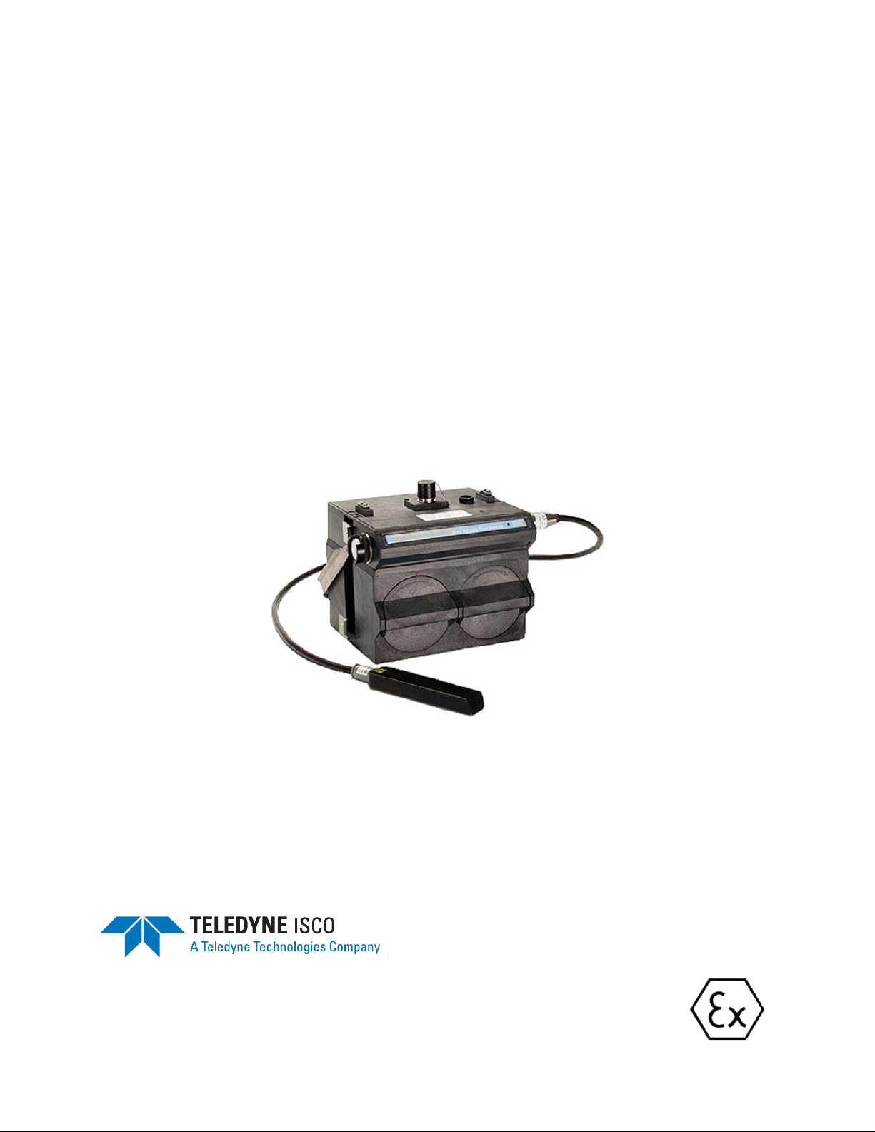
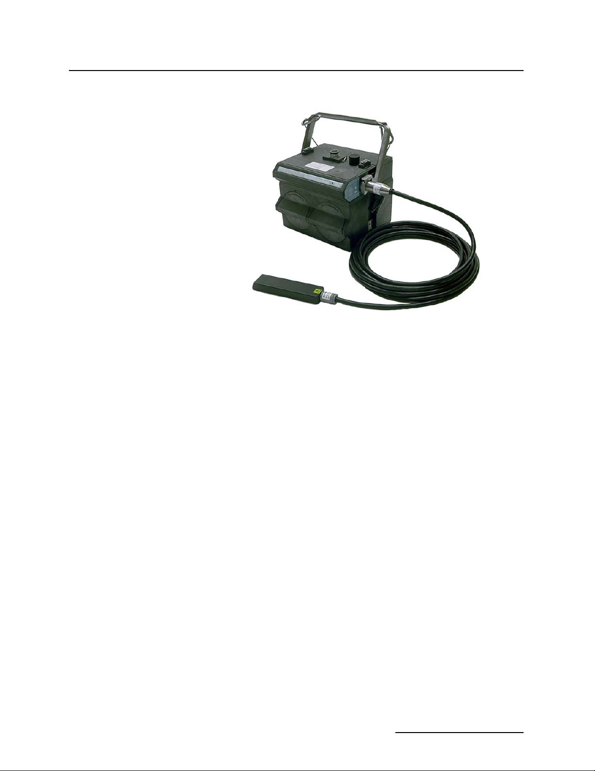
2150EX Module Connected to
2191EX Battery Module and AV2150EX Sensor
Designed for safety The purpose of intrinsic safety is to limit the energy available to
Installation should be completed with adherence to local requirements for ATEX Group II, Category 1G or 2G equipment as
appropriate, and should be done by trained and qualified personnel.
a given circuit or device to a level where electrical discharge
(sparking) cannot ignite the hazardous (flammable or explosive)
atmosphere. With no spark ignition possible, safe operation of
the equipment in areas with hazardous atmospheres is possible.
The durable 2150EX, 2191EX, 2196EX, and 2194EX enclosures
are made with ABS plastic embedded with conductive carbon
fiber, giving the units low surface resistance to minimize electrostatic energy.
The lithium thionyl chloride batteries and the lead acid batteries
used in the 2191EX Battery Module operate at a low voltage and
are contained in sealed battery packs.
The 2150EX system has been designed so that it does not cause
physical injury or other harm due to contact. It does not produce
excessive surface temperature or dangerous radiation. When
used properly, it does not present any non-electrical dangers.
7
Page 8
2150EX Area Velocity Flow System
Safety Information
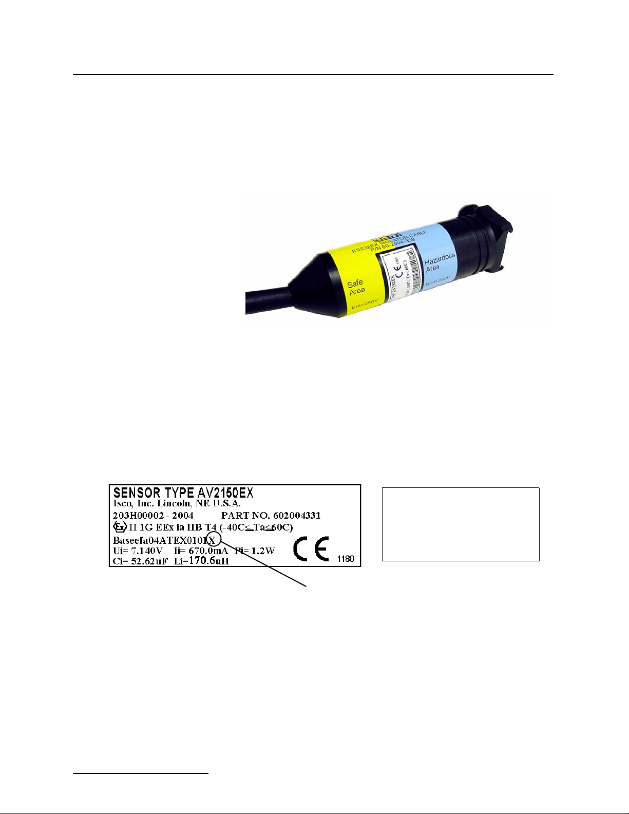
Labels Read all labels carefully before installing the equipment!
The 2150EX and its components are clearly labeled with color
and/or text so you know what can be located in a safe or hazardous area (see figure below). For example, on the label shown
below, light blue is used to indicate the intrinsically safe end and
yellow to indicate the non-protected end of the cable and connector.
Example of Safe and Hazardous Area Labeling on RS232EX Cable
AV2150EX Sensor Cable Labels
Some system components have an X marking, as shown in the
example below. The X marking indicates that there are special
conditions that must be met to ensure intrinsic safety. In the case
of the sensor cable, there is a danger of static electricity. The
cable is labeled with a warning telling you that you should not
rub the sensor with a dry cloth, as this might generate static
electricity.
WARNING
ELECTROSTATIC HAZARD
DO NOT RUB
CLEAN WITH DAMP CLOTH ONLY
X-Marking
8
Page 9
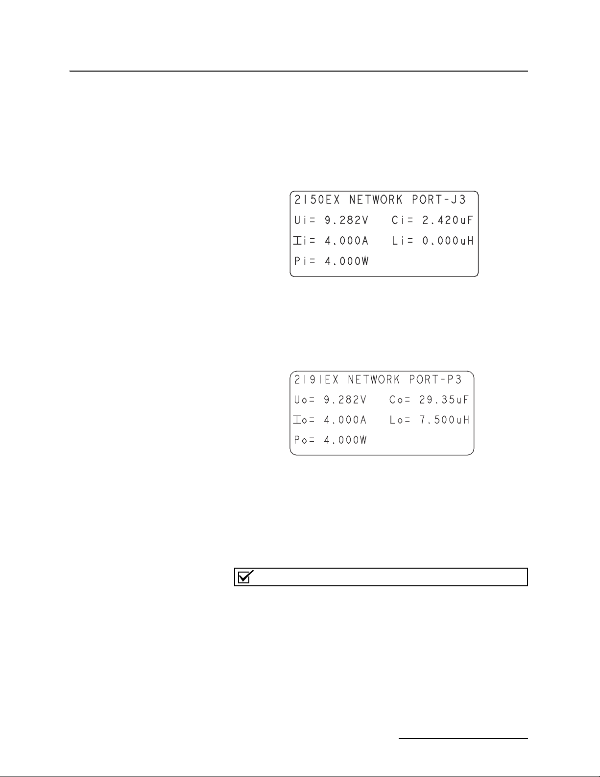
Example of 2150EX Label
2150EX Area Velocity Flow System
Safety Information
Where applicable, the labels contain other information, such as
voltage, serial number identification, etc. For example, the label
shown below indicates the maximum input voltage (U
current (I
), and input power (Pi) that can be applied to the
i
), input
i
2150EX network port without invalidating intrinsic safety. It
also shows the internal capacitance (C
(L
) that must be allowed by any power source.
i
), and internal inductance
i
When you compare the 2150EX label in the figure above with the
2191EX label in the figure below, you can see they provide a
helpful reference so you can make sure your connections are safe.
Example of 2191EX Label
For example, the 2150EX network port cannot have an input
voltage greater than 9.282V. When you look at the label on the
power source (in this case the 2191EX), you can see that the
maximum output voltage is 9.282V. From this you know that you
can safely connect the two, and won’t be providing too much
voltage to the 2150EX unit.
Note
This information is not intended to fully explain entity parameters. Other publications should be referenced for more detailed
explanations.
9
Page 10

2150EX Area Velocity Flow System
Safety Information
Installation Installation of the 2150EX system is described in this manual.
Repair and Maintenance Refer to Section 4 of this manual for instructions regarding
Teledyne Isco, Inc.
Technical Service Dept.
P.O. Box 82531
Lincoln, NE 68501 USA
Phone: (800) 228-4373
(402) 464-0231
FAX: (402) 465-3085
E-mail:
IscoService@teledyne.com
Typical round-pipe installations are shown in Figures 2-1 and
2-2, and Appendix E provides information on general safety procedures for work in manholes and sewers.
When the equipment is installed in accordance with the instructions in this manual, it will not be subjected to dangerous
mechanical or thermal stresses. It should not be installed where
it may be attacked by existing or foreseeable aggressive substances that could damage the module enclosures. The enclosures are made of Acrylonitrile Butadiene Stytene (ABS) plastic.
Substances that may cause damage include organic solvents
(ketones and esters, aromatic and chlorinated hydrocarbons),
alcohols, hydrocarbons, fuels, and UV radiation.
periodic maintenance of the 2150EX and its components.
The internal components of the 2150EX System are not user-ser-
viceable. The case is completely sealed to protect the internal
components. If you think your module requires repair, contact
Teledyne Isco’s Technical Service Department.
Rapidly failing desiccant may indicate a crack.
WARNING
Any cracks in the module case will impair the safety
protection. If this occurs, return the unit to Teledyne Isco
for a replacement.
Components of the AV2150EX Sensor are encapsulated in plastic
resin and are not user-serviceable. If any part of the AV Sensor
fails, it must be replaced.
10
Page 11

2150EX Area Velocity Flow System
Table of Contents
Section 1 Introduction
1.1 Product Description. . . . . . . . . . . . . . . . . . . . . . . . . . . . . . . . . . . . . . . . . . . . . . . . . . 1-1
1.1.1 2150EX Area Velocity Flow System Overview . . . . . . . . . . . . . . . . . . . . . . . 1-2
1.1.2 Level . . . . . . . . . . . . . . . . . . . . . . . . . . . . . . . . . . . . . . . . . . . . . . . . . . . . . . . . 1-2
1.1.3 Velocity . . . . . . . . . . . . . . . . . . . . . . . . . . . . . . . . . . . . . . . . . . . . . . . . . . . . . . 1-2
1.1.4 Flow Rate . . . . . . . . . . . . . . . . . . . . . . . . . . . . . . . . . . . . . . . . . . . . . . . . . . . . 1-3
1.1.5 Total Flow . . . . . . . . . . . . . . . . . . . . . . . . . . . . . . . . . . . . . . . . . . . . . . . . . . . 1-3
1.1.6 Data Storage . . . . . . . . . . . . . . . . . . . . . . . . . . . . . . . . . . . . . . . . . . . . . . . . . 1-3
1.2 Identifying Module Components . . . . . . . . . . . . . . . . . . . . . . . . . . . . . . . . . . . . . . . 1-4
1.3 Technical Specifications . . . . . . . . . . . . . . . . . . . . . . . . . . . . . . . . . . . . . . . . . . . . . . 1-7
Section 2 Preparation and Installation
2.1 Unpacking Instructions . . . . . . . . . . . . . . . . . . . . . . . . . . . . . . . . . . . . . . . . . . . . . . 2-1
2.2 Preparing for Installation. . . . . . . . . . . . . . . . . . . . . . . . . . . . . . . . . . . . . . . . . . . . . 2-2
2.2.1 Safety . . . . . . . . . . . . . . . . . . . . . . . . . . . . . . . . . . . . . . . . . . . . . . . . . . . . . . . 2-2
2.2.2 Locating the Site . . . . . . . . . . . . . . . . . . . . . . . . . . . . . . . . . . . . . . . . . . . . . . 2-2
2.2.3 Channels Without a Primary Device . . . . . . . . . . . . . . . . . . . . . . . . . . . . . . 2-3
2.2.4 Channels With a Primary Device . . . . . . . . . . . . . . . . . . . . . . . . . . . . . . . . . 2-3
2.2.5 2150EX and AV Sensor Mounting Considerations . . . . . . . . . . . . . . . . . . . 2-3
2.3 Site Examples . . . . . . . . . . . . . . . . . . . . . . . . . . . . . . . . . . . . . . . . . . . . . . . . . . . . . . 2-4
2.4 Portable Installations . . . . . . . . . . . . . . . . . . . . . . . . . . . . . . . . . . . . . . . . . . . . . . . . 2-8
2.4.1 Installation Example . . . . . . . . . . . . . . . . . . . . . . . . . . . . . . . . . . . . . . . . . . . 2-8
2.4.2 Install Battery Module Batteries . . . . . . . . . . . . . . . . . . . . . . . . . . . . . . . . . 2-8
2.4.3 Inspect the Desiccant – Battery Module . . . . . . . . . . . . . . . . . . . . . . . . . . 2-10
2.4.4 Inspect the Desiccant – 2150EX Module . . . . . . . . . . . . . . . . . . . . . . . . . . 2-10
2.4.5 Assembling the System . . . . . . . . . . . . . . . . . . . . . . . . . . . . . . . . . . . . . . . . 2-11
2.4.6 Zone 1 Battery Module . . . . . . . . . . . . . . . . . . . . . . . . . . . . . . . . . . . . . . . . 2-13
2.5 Permanent Installations . . . . . . . . . . . . . . . . . . . . . . . . . . . . . . . . . . . . . . . . . . . . . 2-18
2.5.1 Installation Example . . . . . . . . . . . . . . . . . . . . . . . . . . . . . . . . . . . . . . . . . . 2-19
2.6 Network Communication . . . . . . . . . . . . . . . . . . . . . . . . . . . . . . . . . . . . . . . . . . . . 2-21
2.6.1 EX Network Cable . . . . . . . . . . . . . . . . . . . . . . . . . . . . . . . . . . . . . . . . . . . . 2-22
2.6.2 Connecting to a Computer for Interrogation . . . . . . . . . . . . . . . . . . . . . . . 2-23
2.6.3 Connecting to a 2100 Series Network Device . . . . . . . . . . . . . . . . . . . . . . . 2-23
2.7 Connecting the AV2150EX Sensor. . . . . . . . . . . . . . . . . . . . . . . . . . . . . . . . . . . . . 2-25
2.7.1 Positioning the AV Sensor . . . . . . . . . . . . . . . . . . . . . . . . . . . . . . . . . . . . . . 2-27
2.8 Mounting Rings . . . . . . . . . . . . . . . . . . . . . . . . . . . . . . . . . . . . . . . . . . . . . . . . . . . . 2-28
2.8.1 Spring Rings . . . . . . . . . . . . . . . . . . . . . . . . . . . . . . . . . . . . . . . . . . . . . . . . . 2-29
2.8.2 Scissors Mounting Ring . . . . . . . . . . . . . . . . . . . . . . . . . . . . . . . . . . . . . . . . 2-30
2.8.3 Completing the AV Sensor Installation . . . . . . . . . . . . . . . . . . . . . . . . . . . 2-32
2.9 Final Installation Check . . . . . . . . . . . . . . . . . . . . . . . . . . . . . . . . . . . . . . . . . . . . . 2-33
2.9.1 Program the Module . . . . . . . . . . . . . . . . . . . . . . . . . . . . . . . . . . . . . . . . . . 2-33
Section 3 Programming
3.1 Overview . . . . . . . . . . . . . . . . . . . . . . . . . . . . . . . . . . . . . . . . . . . . . . . . . . . . . . . . . . 3-1
3.2 Flowlink Connections . . . . . . . . . . . . . . . . . . . . . . . . . . . . . . . . . . . . . . . . . . . . . . . . 3-1
3.2.1 Site Configuration Stability . . . . . . . . . . . . . . . . . . . . . . . . . . . . . . . . . . . . . 3-2
11
Page 12

2150EX Area Velocity Flow System
Table of Contents
3.3 Program Settings. . . . . . . . . . . . . . . . . . . . . . . . . . . . . . . . . . . . . . . . . . . . . . . . . . . . 3-2
3.3.1 Level . . . . . . . . . . . . . . . . . . . . . . . . . . . . . . . . . . . . . . . . . . . . . . . . . . . . . . . . 3-3
3.3.2 Zero Level Offset . . . . . . . . . . . . . . . . . . . . . . . . . . . . . . . . . . . . . . . . . . . . . . 3-4
3.3.3 No Velocity Data and Flow Rates . . . . . . . . . . . . . . . . . . . . . . . . . . . . . . . . . 3-5
3.3.4 Flow Conversion . . . . . . . . . . . . . . . . . . . . . . . . . . . . . . . . . . . . . . . . . . . . . . 3-5
3.3.5 Silt Level . . . . . . . . . . . . . . . . . . . . . . . . . . . . . . . . . . . . . . . . . . . . . . . . . . . . 3-7
3.3.6 Data Storage Rates . . . . . . . . . . . . . . . . . . . . . . . . . . . . . . . . . . . . . . . . . . . . 3-7
3.3.7 Site Name . . . . . . . . . . . . . . . . . . . . . . . . . . . . . . . . . . . . . . . . . . . . . . . . . . . . 3-8
3.3.8 Module Name . . . . . . . . . . . . . . . . . . . . . . . . . . . . . . . . . . . . . . . . . . . . . . . . . 3-8
Section 4 Modbus Protocol
4.1 Introduction. . . . . . . . . . . . . . . . . . . . . . . . . . . . . . . . . . . . . . . . . . . . . . . . . . . . . . . . 4-1
4.2 Operation . . . . . . . . . . . . . . . . . . . . . . . . . . . . . . . . . . . . . . . . . . . . . . . . . . . . . . . . . . 4-1
4.2.1 Establishing Communication . . . . . . . . . . . . . . . . . . . . . . . . . . . . . . . . . . . . 4-2
4.2.2 Module Addressing . . . . . . . . . . . . . . . . . . . . . . . . . . . . . . . . . . . . . . . . . . . . 4-2
4.3 Configurations. . . . . . . . . . . . . . . . . . . . . . . . . . . . . . . . . . . . . . . . . . . . . . . . . . . . . . 4-3
4.4 Glossary of Terms . . . . . . . . . . . . . . . . . . . . . . . . . . . . . . . . . . . . . . . . . . . . . . . . . . . 4-4
4.5 Common Acronyms . . . . . . . . . . . . . . . . . . . . . . . . . . . . . . . . . . . . . . . . . . . . . . . . . . 4-5
4.6 Register Specifications . . . . . . . . . . . . . . . . . . . . . . . . . . . . . . . . . . . . . . . . . . . . . . . 4-6
Section 5 Maintenance
5.1 Maintenance Overview . . . . . . . . . . . . . . . . . . . . . . . . . . . . . . . . . . . . . . . . . . . . . . . 5-1
5.2 Maintenance Kits . . . . . . . . . . . . . . . . . . . . . . . . . . . . . . . . . . . . . . . . . . . . . . . . . . . 5-1
5.3 2191EX Batteries . . . . . . . . . . . . . . . . . . . . . . . . . . . . . . . . . . . . . . . . . . . . . . . . . . . 5-2
5.3.1 LTC2191EX Lithium Batteries . . . . . . . . . . . . . . . . . . . . . . . . . . . . . . . . . . . 5-2
5.3.2 SLA2191EX Lead-Acid Batteries . . . . . . . . . . . . . . . . . . . . . . . . . . . . . . . . . 5-4
5.4 Desiccant . . . . . . . . . . . . . . . . . . . . . . . . . . . . . . . . . . . . . . . . . . . . . . . . . . . . . . . . . . 5-8
5.4.1 Replacing the Desiccant: AV Module . . . . . . . . . . . . . . . . . . . . . . . . . . . . . . 5-8
5.4.2 Replacing the Desiccant: Battery Module . . . . . . . . . . . . . . . . . . . . . . . . . . 5-8
5.4.3 Reactivating the Desiccant . . . . . . . . . . . . . . . . . . . . . . . . . . . . . . . . . . . . . . 5-9
5.5 Channel Conditions. . . . . . . . . . . . . . . . . . . . . . . . . . . . . . . . . . . . . . . . . . . . . . . . . . 5-9
5.6 Other Maintenance . . . . . . . . . . . . . . . . . . . . . . . . . . . . . . . . . . . . . . . . . . . . . . . . . . 5-9
5.6.1 Hydrophobic Filter . . . . . . . . . . . . . . . . . . . . . . . . . . . . . . . . . . . . . . . . . . . . 5-10
5.6.2 Cleaning . . . . . . . . . . . . . . . . . . . . . . . . . . . . . . . . . . . . . . . . . . . . . . . . . . . . 5-10
5.6.3 Sensor Cable Inspection . . . . . . . . . . . . . . . . . . . . . . . . . . . . . . . . . . . . . . . 5-11
5.7 How to Obtain Service . . . . . . . . . . . . . . . . . . . . . . . . . . . . . . . . . . . . . . . . . . . . . . 5-11
5.7.1 Diagnostics . . . . . . . . . . . . . . . . . . . . . . . . . . . . . . . . . . . . . . . . . . . . . . . . . . 5-11
Appendix A Replacement Parts
A.1 Replacement Parts Diagrams and Listings . . . . . . . . . . . . . . . . . . . . . . . . . . . . . . A-1
Appendix B Accessories
B.1 How to Order. . . . . . . . . . . . . . . . . . . . . . . . . . . . . . . . . . . . . . . . . . . . . . . . . . . . . . . B-1
B.2 General Accessories . . . . . . . . . . . . . . . . . . . . . . . . . . . . . . . . . . . . . . . . . . . . . . . . . B-1
B.3 Maintenance Kits . . . . . . . . . . . . . . . . . . . . . . . . . . . . . . . . . . . . . . . . . . . . . . . . . . . B-2
B.4 AV Sensor Mounting Accessories. . . . . . . . . . . . . . . . . . . . . . . . . . . . . . . . . . . . . . . B-2
12
Appendix C Material Safety Data Sheets
C.1 Overview . . . . . . . . . . . . . . . . . . . . . . . . . . . . . . . . . . . . . . . . . . . . . . . . . . . . . . . . . . C-1
Appendix D General Safety Procedures
D.1 Hazards. . . . . . . . . . . . . . . . . . . . . . . . . . . . . . . . . . . . . . . . . . . . . . . . . . . . . . . . . . . D-1
Page 13

2150EX Area Velocity Flow System
Table of Contents
D.2 Planning . . . . . . . . . . . . . . . . . . . . . . . . . . . . . . . . . . . . . . . . . . . . . . . . . . . . . . . . . . D-2
D.3 Adverse Atmospheres. . . . . . . . . . . . . . . . . . . . . . . . . . . . . . . . . . . . . . . . . . . . . . . . D-2
D.4 Entering Manholes. . . . . . . . . . . . . . . . . . . . . . . . . . . . . . . . . . . . . . . . . . . . . . . . . . D-2
D.4.1 Traffic Protection . . . . . . . . . . . . . . . . . . . . . . . . . . . . . . . . . . . . . . . . . . . . . D-3
D.4.2 Removing the Covers . . . . . . . . . . . . . . . . . . . . . . . . . . . . . . . . . . . . . . . . . . D-3
D.4.3 Other Precautions . . . . . . . . . . . . . . . . . . . . . . . . . . . . . . . . . . . . . . . . . . . . . D-3
D.4.4 Emergencies . . . . . . . . . . . . . . . . . . . . . . . . . . . . . . . . . . . . . . . . . . . . . . . . . D-4
D.4.5 Field Equipment . . . . . . . . . . . . . . . . . . . . . . . . . . . . . . . . . . . . . . . . . . . . . . D-4
D.5 Lethal Atmospheres in Sewers . . . . . . . . . . . . . . . . . . . . . . . . . . . . . . . . . . . . . . . . D-4
List of Figures
1-1 2150EX - Top and Bottom Views . . . . . . . . . . . . . . . . . . . . . . . . . . . . . . . . . . . . . . . 1-4
1-2 2150EX Connected to 2191EX- Top Right View . . . . . . . . . . . . . . . . . . . . . . . . . . . 1-5
1-3 Components – AV2150EX Area Velocity Sensor . . . . . . . . . . . . . . . . . . . . . . . . . . 1-6
1-4 2191EX and 2196EX Battery Components . . . . . . . . . . . . . . . . . . . . . . . . . . . . . . . 1-7
1-5 2150EX Area Velocity Flow System Communication Connector Pins . . . . . . . . 1-11
2-1 Typical Round-pipe Installation Connected to a
Laptop Computer (Portable Installation, see section 2.4) . . . . . . . . . . . . . . . . . . . 2-5
2-2 Typical Round-pipe Installation Connected to a
2101 Field Wizard (Portable Installation, see section 2.4) . . . . . . . . . . . . . . . . . . 2-6
2-3 Typical Round-pipe Installation Connected to a
2194EX Module and Laptop
(Permanent Installation, see section 2.5) . . . . . . . . . . . . . . . . . . . . . . . . . . . . . . . . 2-7
2-4 Illustration of Battery Packs . . . . . . . . . . . . . . . . . . . . . . . . . . . . . . . . . . . . . . . . . . 2-9
2-5 Label Markings for LTC2191EX and SLA2191EX Battery Packs . . . . . . . . . . . . 2-9
2-6 Assembling a basic portable system . . . . . . . . . . . . . . . . . . . . . . . . . . . . . . . . . . . 2-11
2-7 Flowlink low-voltage warning . . . . . . . . . . . . . . . . . . . . . . . . . . . . . . . . . . . . . . . . 2-14
2-8 Location of 2196EX charging terminals . . . . . . . . . . . . . . . . . . . . . . . . . . . . . . . . 2-15
2-9 Detailed view of charging circuit board . . . . . . . . . . . . . . . . . . . . . . . . . . . . . . . . 2-16
2-10 2196EX battery module and labeling . . . . . . . . . . . . . . . . . . . . . . . . . . . . . . . . . 2-17
2-11 Amphenol connector pins for 12V adapter cable 69-2004-451 . . . . . . . . . . . . . 2-18
2-12 2194EX labels and cable connector . . . . . . . . . . . . . . . . . . . . . . . . . . . . . . . . . . 2-20
2-13 Network cable connector and wiring . . . . . . . . . . . . . . . . . . . . . . . . . . . . . . . . . 2-20
2-14 Network cable conduit fittings . . . . . . . . . . . . . . . . . . . . . . . . . . . . . . . . . . . . . . 2-21
2-15 Wiring the socket insert . . . . . . . . . . . . . . . . . . . . . . . . . . . . . . . . . . . . . . . . . . . 2-21
2-16 EX Network Cable for Connection to an Isolator Cable . . . . . . . . . . . . . . . . . . 2-22
2-17 RS232EX Isolator Cable for Connection to a Computer . . . . . . . . . . . . . . . . . . 2-23
2-18 RS485EX Isolator Cable for Connection to a 2100 Series Network Device . . . 2-24
2-19 Connecting the AV Sensor . . . . . . . . . . . . . . . . . . . . . . . . . . . . . . . . . . . . . . . . . 2-26
2-20 AV2150EX Sensor Cable Labels . . . . . . . . . . . . . . . . . . . . . . . . . . . . . . . . . . . . . 2-26
2-21 Sensor Installed on a Spring Ring . . . . . . . . . . . . . . . . . . . . . . . . . . . . . . . . . . . 2-29
2-22 Scissors Ring adjustment . . . . . . . . . . . . . . . . . . . . . . . . . . . . . . . . . . . . . . . . . . 2-32
3-1 Connection to a Laptop, Using Cables P/N 60-2004-336 and 60-2004-339 . . . . . . 3-1
3-2 Preferred Measurement Location . . . . . . . . . . . . . . . . . . . . . . . . . . . . . . . . . . . . . . 3-3
3-3 Zero Level Offset Measurement . . . . . . . . . . . . . . . . . . . . . . . . . . . . . . . . . . . . . . . 3-4
4-1 Configuration Example (Direct Connection Shown) . . . . . . . . . . . . . . . . . . . . . . . 4-3
5-1 Illustration of LTC2191EX Battery Packs . . . . . . . . . . . . . . . . . . . . . . . . . . . . . . . 5-3
5-2 SLA2191EX Battery Pack Voltage Chart . . . . . . . . . . . . . . . . . . . . . . . . . . . . . . . . 5-4
5-3 Lead-Acid SLA2191 EX Battery Packs and 8V2191SLA Charger . . . . . . . . . . . . 5-5
5-4 Inserting an SLA2191EX Battery Pack into the Charger . . . . . . . . . . . . . . . . . . . 5-6
5-5 Illustration of Battery Packs . . . . . . . . . . . . . . . . . . . . . . . . . . . . . . . . . . . . . . . . . . 5-7
13
Page 14

2150EX Area Velocity Flow System
Table of Contents
List of Tables
1-1 2150EX Area Velocity Flow Module - Top and Bottom Views . . . . . . . . . . . . . . . . 1-4
1-2 2150EX Area Velocity Flow Module - Top Right View . . . . . . . . . . . . . . . . . . . . . 1-5
1-3 Components – AV2150EX Area Velocity Sensor . . . . . . . . . . . . . . . . . . . . . . . . . . 1-6
1-4 Battery Components - 2191EX and 2196EX . . . . . . . . . . . . . . . . . . . . . . . . . . . . . 1-7
1-5 Technical Specifications – 2150EX and 2191EX Modules
(Zones 0, 1, and 2) . . . . . . . . . . . . . . . . . . . . . . . . . . . . . . . . . . . . . . . . . . . . . . . . . . 1-8
1-6 Technical Specifications - 2196EX Battery Module
(Zones 1 and 2) . . . . . . . . . . . . . . . . . . . . . . . . . . . . . . . . . . . . . . . . . . . . . . . . . . . . . 1-9
1-7 Technical Specifications - 2194EX Interface Module
(Associated Apparatus) . . . . . . . . . . . . . . . . . . . . . . . . . . . . . . . . . . . . . . . . . . . . . . 1-9
1-8 Specifications – AV2150EX Area Velocity Sensor
(Zones 0, 1, and 2) . . . . . . . . . . . . . . . . . . . . . . . . . . . . . . . . . . . . . . . . . . . . . . . . . 1-10
1-9 Communication Connector Pins . . . . . . . . . . . . . . . . . . . . . . . . . . . . . . . . . . . . . . 1-11
3-1 Flow Conversion Methods . . . . . . . . . . . . . . . . . . . . . . . . . . . . . . . . . . . . . . . . . . . . 3-6
4-1 Modbus ASCII Address 1 Register Definitions . . . . . . . . . . . . . . . . . . . . . . . . . . . . 4-6
4-2 Modbus ASCII Address 2-(N+1) Register Definitions . . . . . . . . . . . . . . . . . . . . . . 4-7
4-3 Measurement Parameters by Model Number* . . . . . . . . . . . . . . . . . . . . . . . . . . . . 4-9
D-1 Hazardous Gases . . . . . . . . . . . . . . . . . . . . . . . . . . . . . . . . . . . . . . . . . . . . . . . . . . . D-7
14
Page 15

2150EX Area Velocity Flow Module
Section 1 Introduction
1.1 Product Description The 2150EX Area Velocity Flow Module is part of Isco’s 2100
Series. The 2100 Series measures parameters of open channel
flow streams.
The intrinsically safe 2150EX is intended for use in potentially
explosive atmospheres, and complies with ATEX Directive
94/9/EC. The 2150EX is Group II, Category 1G or 2G equipment
as appropriate for use in Hazardous Zones 0, 1, and 2.
The purpose of intrinsic safety is to limit the energy available to
a given circuit or device to a level where electrical discharge
(sparking) cannot ignite the hazardous (flammable or explosive)
atmosphere. With no spark ignition possible, safe operation of
the equipment in areas with potentially explosive atmospheres is
possible.
The standard 2100 Series is designed to be modular so that you
can expand the system by stacking modules to meet your data
collection needs. The 2150EX incorporates this modularity,
allowing up to two 2150EX modules to be stacked on one 2191EX
or 2196EX battery module.
The 2150EX is paired with Isco’s Flowlink software. With this
full-featured application software, you can quickly set up the
module, retrieve measurement data, manage the sites, and
analyze the data, and update the module’s own software, all
without entering the hazardous area.
The module’s data storage memory is quite flexible, able to store
the measurements in intervals from 15 seconds to 24 hours. The
module can also be configured for variable rate data storage.
Variable rates allow you to store data at a different interval
when a programmed condition occurs.
The module’s program and collected data are stored in flash
memory for security. Flash memory retains data without the
concern of power failures or aging backup batteries. Its capacity
is more than sufficient for most applications. The data storage
memory can hold approximately 79,000 readings – the equivalent of nine months of level and velocity data when stored at
fifteen minute intervals. The flash memory also stores sensor
level adjustment information. A separate flash memory device
inside the module stores the operating firmware.
The rugged 2150EX components are rated NEMA 4X, 6P (IP68).
The permanently sealed enclosures are designed to meet the
environmental demands of many sewer flow monitoring applications. All connections between sensors and communication cables
“lock” in place. Each locking mechanism strongly secures the
components and ensures a watertight seal.
1-1
Page 16
2150EX Area Velocity Flow Module
Section 1 Introduction
1.1.1 2150EX Area Velocity Flow System Overview
AV Module
The 2150EX measures liquid level and average stream velocity,
and calculates the flow rate and total flow. The liquid level and
velocity measurements are read from an attached Area Velocity
(AV) Sensor that is placed in the flow stream. Flow rate calculations are performed internally using the measured parameters
from the AV Sensor. Additionally, the 2150EX can measure its
input voltage.
The 2150EX is designed to provide durable operation with only a
minimal amount of routine maintenance, all of which may be
performed in the field, while keeping in mind restrictions for
potentially explosive atmospheres. Typically, the 2150EX and its
AV Se n s o r
AV2150EX Sensor will only require that you keep the stream free
from excessive debris, and replace or recharge spent desiccant
and batteries. Sections 1.1.2 through 1.1.6 describe the 2150EX
and sensor in greater detail.
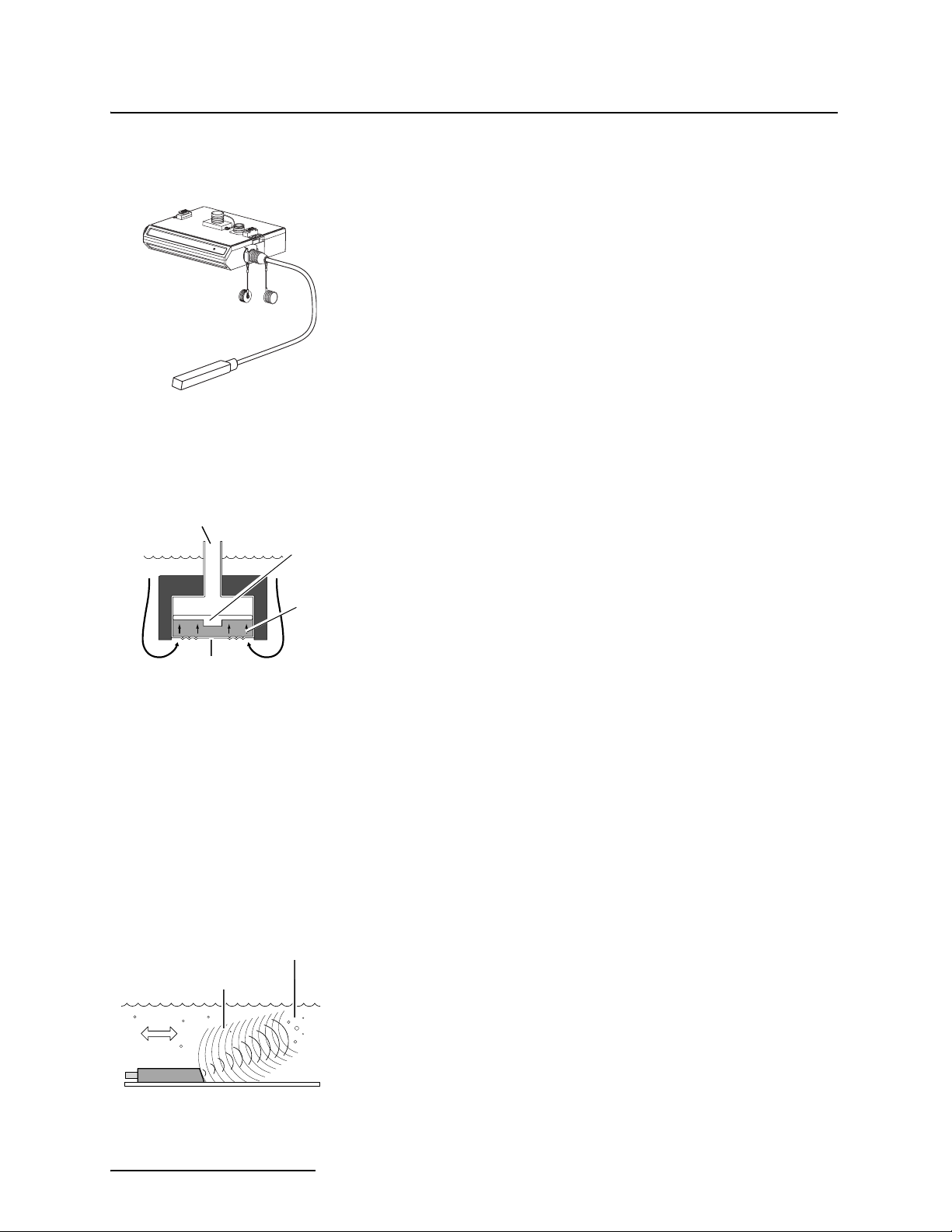
1.1.2 Level The AV Sensor’s internal differential pressure transducer mea-
sures the liquid level. The transducer is a small piezo-resistive
chip that detects the difference of the pressures felt on the inner
reference to
atmosphere
piezo-
resistive
transducer
and outer face.
The stainless steel outer diaphragm is exposed to the flow stream
through the ports under the AV Sensor. The pressure felt on the
outer diaphragm is transferred to the outer face of the trans-
silicone
fluid
ducer through a silicone fluid medium. The outer diaphragm and
fluid isolate the sensitive transducer from direct exposure to the
stream. The inner face of the transducer is exposed, or referenced, to the atmosphere through the internal vent tube that
outer
diaphragm
runs the full length of the AV Sensor’s cable.
The difference between the pressures exerted on the transducer
is the hydrostatic pressure. Hydrostatic pressure is proportional
to the level of the stream. The Isco AV2150EX sensor uses state
of the art techniques to ensure accuracy throughout the environmental operating range. At the factory each sensor is measured
at scores of pressure and temperature levels to precisely characterize the unique transducer. These calibration results are digitally stored within the sensor's flash memory. During readings
the sensor's microcontroller applies the known correction factor
to produce highly accurate level readings.
1.1.3 Velocity The AV Sensor measures average velocity by using ultrasonic
sound waves and the Doppler effect. The Doppler effect states
that the frequency of a sound wave (or other wave) passed from
Ultrasonic
sound waves
Particles or
air bubbles
one body to another is relative to both their motions. As the two
approach each other, the frequency increases; as they move
apart, the frequency decreases.
The AV Sensor contains a pair of ultrasonic transducers. One
Flow
transducer transmits the ultrasonic sound wave. As the transmitted wave travels through the stream, particles and bubbles
carried by the stream reflect the sound wave back towards the
AV Sensor. The second transducer receives the reflected wave.
1-2
Page 17
2150EX Area Velocity Flow Module
Section 1 Introduction
Circuits internal to the module compare the frequencies of the
sound waves and extract the difference. An increase or decrease
in the frequency of the reflected wave indicates forward or
reverse flow. The degree of change is proportional to the velocity
of the flow stream.
1.1.4 Flow Rate Using measurements from the AV Sensor, the 2150EX can cal-
culate the flow rate. Many different flow rate conversion methods
are supported:
• Area Velocity
•Data Points
• Manning Formula
• Two-term Polynomial Equations
•Flumes
•Weirs
Often the 2150EX is chosen for applications where a primary
device is not available, nor is it practical to install a primary
device. Therefore, area velocity is usually the conversion method
of choice.
The 2150EX is capable of calculating and storing any two conversion methods simultaneously. This feature is useful when it is
necessary to validate a flow conversion method. For example, the
flow rate at a new site programmed for area velocity conversion
can be directly compared to the flow rate calculated using a
Manning formula.
1.1.5 Total Flow The 2150EX can calculate and report the total flow. You can set
up the system to monitor net, positive, or negative total flow from
either of the calculated flow rates.
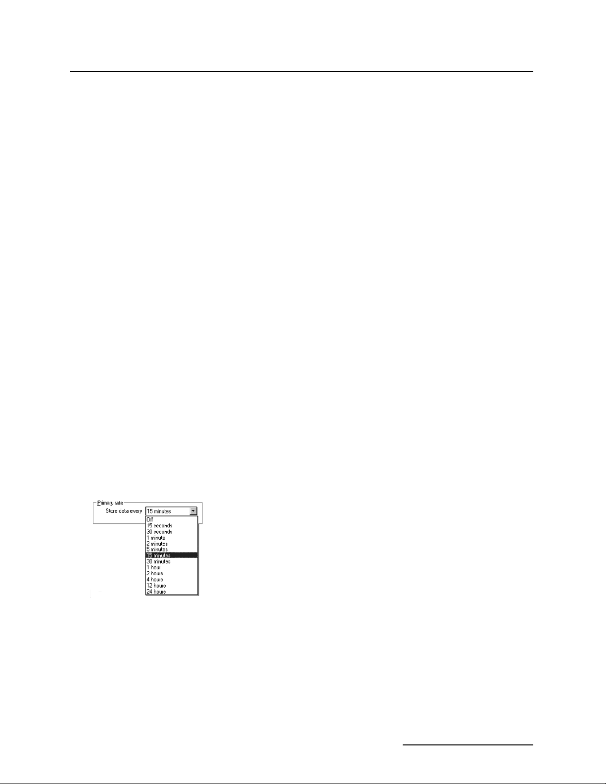
1.1.6 Data Storage Through Flowlink, you configure which type of data is logged and
the storage rate. For each measurement, the Data Storage Setup
window lets you turn the primary rate off, or select a rate from 15
seconds to once every 24 hours. If the primary rate is turned off,
the 2150EX will not store the measurement (unless a secondary
rate is selected). However, the 2150EX will still take readings if
that measurement type is necessary for a calculation.
Secondary rates are used to log data at a different rate when a
user-defined condition exists. For example, a secondary rate can
be used to increase the level and velocity data storage rate when
level is greater than or equal to a point of interest. Secondary
rates give you the best resolution of data, but only when it is
needed. Until the condition is met, the module will conserve
power and memory by storing the data at the primary storage
rate. Like the primary rate, you can turn the secondary rate off,
or select a storage rate of 15 seconds to every 24 hours.
Time Resolution The time resolution of each measurement is one second. That is,
readings are taken at the same time as the time stamp, not collected and averaged over a period of time before the stamp.
1-3
Page 18
2150EX Area Velocity Flow Module
Section 1 Introduction
Rollover Memory Whether the measurements are stored at the primary or sec-
ondary rate, they are stored in a rollover type of memory. When
full, the module overwrites the oldest data with the newest
readings.
1.2 Identifying Module Components
Bottom View
6
The various components of the 2150EX are shown in Figures 1-1
through 1-4. Items referenced in the figures are described in
Tables 1-1 through 1-4.
Top View
2
3
1
4
7
5
Figure 1-1 2150EX - Top and Bottom Views
Table 1-1 2150EX Area Velocity Flow Module - Top and Bottom Views
Item No. Fig. 2-1 Name Description
1 Latch Latches the module in place. A latch release is located on the
right side of the module.
2 Communication Connector
(shown uncapped)
3 Connector Cap
(shown in holder)
4 Desiccant Cartridge and
Hydrophobic Filter
5 Communication Indicator Illuminates when module communications are active.
6 Communication Connector
(shown capped)
7 Cap Holder Used to store the Connector Cap.
Upper communication port; used to connect to another module, or to a PC running Flowlink software.
Insert into unused communication connector to terminate the
network and protect it from moisture damage. When the communication connector is in use, the cap must be stowed in its
holder to protect the terminating components inside the cap.
The cartridge holds desiccant that dries the reference air. The
filter prevents moisture from entering the reference line.
Used to connect the module to the 2191EX or 2196EX battery
module, or to another 2150EX module. When the communication connector is in use, the cap must be stowed in its holder to
protect the terminating components inside the cap.
1-4
Page 19
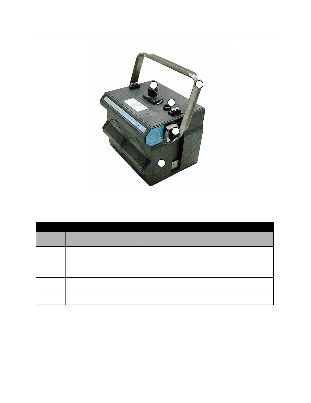
2150EX Area Velocity Flow Module
Section 1 Introduction
2
5
Figure 1-2 2150EX Connected to 2191EX- Top Right View
Table 1-2 2150EX Area Velocity Flow Module - Top Right View
1
3
4
Item No.
Fig. 2-2
1 Carrying Handle Used to lift and carry the unit.
2 Communication Connector
3 Cap Holder Used to store the connector cap.
4 AV Sensor Receptacle Port used to attach the AV Sensor. Insert the protective cap
5 2191EX Used to store battery packs and provide a source of power for
Name Description
(shown capped)
Upper communication port, used to connect to another module
or to a PC running Flowlink software.
when not in use.
the 2150EX.
1-5
Page 20
2150EX Area Velocity Flow Module
Section 1 Introduction
1
3
2
4
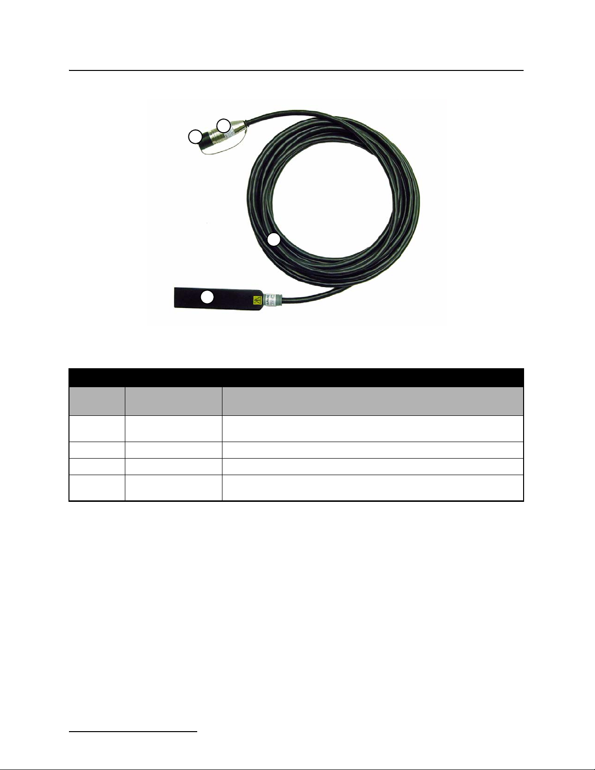
Figure 1-3 Components – AV2150EX Area Velocity Sensor
Table 1-3 Components – AV2150EX Area Velocity Sensor
Item No.
Fig. 1-3
1 Connector Cap Protects the connector. When the connector is not in use, this cap must be in
2 Connector Attaches to the AV Sensor receptacle on the 2150EX Module.
3 AV Sensor Body The AV Sensor Body is placed in the flow stream to measure level and velocity.
4 Cable 10.0 m (32.8 ft) cable containing the reference air tubing and conductors to
Name Description
place to prevent damage to the connector pins and reference air tubing.
transfer level data, velocity data, and AV Sensor power.
1-6
Page 21
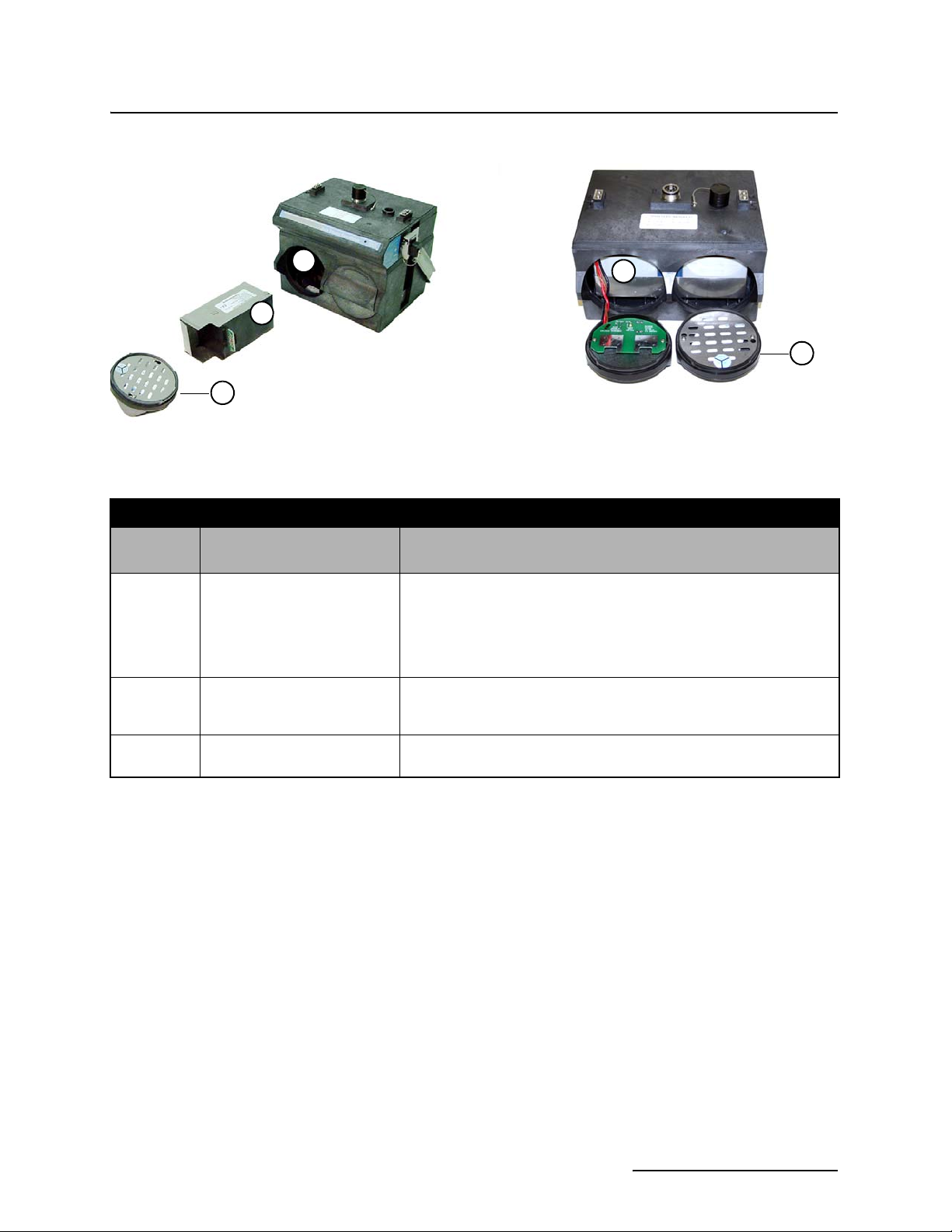
2191EX2191EX 2196EX
2150EX Area Velocity Flow Module
Section 1 Introduction
3
3
2
1
Figure 1-4 2191EX and 2196EX Battery Components
Table 1-4 Battery Components - 2191EX and 2196EX
Item No.
Fig. 1-4
1 Battery Door
2 Lithium Battery Pack (2)
3 Battery Cavity 2191EX: The battery packs are inserted into the battery cavities.
Name Description
The quarter-turn door seals the battery cavity.
2191EX: Inside each door is a humidity indicator and a bag of
desiccant to prevent internal moisture damage.
2196EX: The right door has one humidity indicator and bag of
desiccant, while the left door houses the charging circuit board for the
batteries.
Use only the lithium or lead-acid battery packs supplied by Teledyne
or
Lead-Acid Battery Pack (2)
Isco. Operation requires two of either battery type.
2196EX: The batteries are integral to the module and not removable.
1
1.3 Technical Specifications
This section lists technical information about the 2150EX Area
Velocity Flow Module and its related components.
• Table 1-5 lists the technical specifications for the
2150EX and 2191EX Modules, and also the battery
packs.
• Table 1-6 lists the technical specifications for the
2196EX Zone 1 battery module.
• Table 1-7 lists the technical specifications for the
2194EX network interface module.
• Table 1-8 lists the technical specifications for the
AV2150EX Area Velocity Sensor.
• Figure 1-5 and Table 1-9 list information about the
2150EX’s communication connector.
1-7
Page 22

2150EX Area Velocity Flow Module
Section 1 Introduction
Table 1-5 Technical Specifications – 2150EX and 2191EX Modules
(Zones 0, 1, and 2)
Size (H×W×D)
2150EX connected to 2191EX 22.6 × 28.0 × 19.3 cm 8.9 × 11.0 × 7.6 in.
Weight
(without batteries)
(with lithium battery packs)
(with lead-acid battery packs)
Material ABS plastic, stainless steel
Enclosure (self-certified) NEMA 4X, 6P IP 68
Power 7.0 to 9.0 VDC, 100 mA typical at 8 VDC, 1 mA standby
Batteries LTC2191EX lithium or SLA2191EX lead-acid batteries, quantity 2 battery packs
3.00 kg 6.6 lb
4.20 kg 9.2 lb
7.10 kg 15.7 lb
Typical Battery Life (estimated)
(assumes 23°C; actual
performance is affected by
site conditions)
Operating Temperature -40° to 60°C -40° to 140°F
Storage Temperature -40° to 60°C -40° to 140°F
Program Memory Non-volatile, programmable flash; can be updated using PC without opening
Flow Rate Conversions Up to 2 independent level-to-area and/or level-to-flow rate conversions
Level-to-Area Conversions
Channel Shapes Round, U-shaped, rectangular, trapezoidal, elliptical, with silt correction
Data Points Up to 50 level-area points
Level-to-Flow Rate Conversions
Weirs V-notch, rectangular, Cipolletti, Isco Flow Metering Inserts, Thel-Mar
Flumes Parshall, Palmer-Bowlus, Leopold-Lagco, trapezoidal, H, HS, HL
Manning Formula Round, U-shaped, rectangular, trapezoidal
Data Points Up to 50 level-flow rate points
Level Velocity LTC2191EX SLA2191EX
Data Storage Interval Lithium Batteries Rechargeable Lead-Acid Batteries
15 minutes 49 months 157 days
5 minutes 21 months 64 days
2 minutes 8 months 31 days
1 minute 4 months 18 days
(lead-acid battery packs have an operating temperature of -20° to 60°C or -4° to 140°F)
enclosure or entering hazardous area; retains user program after updating
Equation 2-term polynomial
Total Flow Calculations Up to 2 independent, net, positive or negative, based on either flow rate conversion
Data Storage Memory Non-volatile flash; retains stored data during program updates
Capacity 395,000 bytes (up to 79,000 readings, equal to over 270 days of level and velocity
readings at 15 minute intervals, plus total flow and input voltage readings at 24
hour intervals). Bytes per reading is 5.
Data Types Level, velocity, flow rate 1, flow rate 2, total flow 1, total flow 2, input voltage
Storage Mode Rollover with variable rate data storage based on level, velocity, flow rate 1, flow
rate 2, total flow 1, total flow 2, or input voltage
Storage Interval 15 or 30 seconds; 1, 2, 5, 15 or 30 minutes; or 1, 2, 4, 12 or 24 hours
Setup and Data Retrieval Serial connection to IBM PC or compatible computer with Isco Flowlink Software
Version 4.16 or greater
Baud Rate 38,400
1-8
Page 23

2150EX Area Velocity Flow Module
Section 1 Introduction
Table 1-6 Technical Specifications - 2196EX Battery Module
(Zones 1 and 2)
Size (HxWxD) 14.94 x 23.12 x 19.3 cm 5.88 x 9.13 x 7.6 in.
Weight 5.77 kg 12.71 lb
Enclosure (self-certified) NEMA 4X, 6P IP 68
Operating and Storage Temperature -40 °C to 60 °C -40 °F to 140 °F
Power Output Nominal: 8 VDC
Maximum: 9.28 VDC
Charger Input Nominal: 13.5 to 14.7 volts
Absolute Maximum: 20 volts, 2.0A
NOTE:
The serial tag of the 2196EX Module contains important X marking, indicating special safety conditions that must be
observed. See Important Information Regarding "X" Marking on page 2-17 for more information.
Table 1-7 Technical Specifications - 2194EX Interface Module
(Associated Apparatus)
Size (H×W×D) 7.37 x 28.7 x 19.05 cm 2.9 x 11.3 x 7.5 in.
Weight 9 kg 2 lb
Enclosure (self-certified) NEMA 4X, 6P IP 68
Operating Temperature -20 to 60 °C -4 to 140 °F
Storage Temperature -40 to 60 °C -40 to 140 °F
Power 9 to 26.5 VDC (nominal 12 or 24 VDC)
150 mA typical @ 12 VDC
Output 8.8 VDC, nominal
Number of 2150EX flow modules powered:
with 75m interface cable: 2
with 150m interface cable: 1
Communication Side connector: Isco EX node network compatible explosion protected devices
Top & Bottom connectors: Isco node network / PC compatible
NOTE:
The serial tag of the 2194EX Module contains important X marking, indicating special safety conditions that must
be observed. See Important Information Regarding "X" Marking on page 2-19 for more information.
1-9
Page 24

2150EX Area Velocity Flow Module
Section 1 Introduction
Table 1-8 Specifications – AV2150EX Area Velocity Sensor
(Zones 0, 1, and 2)
Materials
Sensor Epoxy, chlorinated polyvinyl chloride (CPVC), stainless steel
Cable Polyvinyl chloride (PVC), chlorinated polyvinyl chloride (CPVC), stainless steel
Size (H×W×D) 1.9 × 3.3 × 15.2 cm 0.75 × 1.31 × 6.00 in.
Cable Length 10.0 m 32.8 ft.
Cable Diameter 0.9 cm 0.37 in.
Weight (including cable) 1.02 kg 2.24 lbs
Level Measurement
Method Submerged pressure transducer mounted in the flow stream
Transducer Type Differential linear integrated circuit pressure transducer
1
Range
Maximum Allowable Level 10.5 m 34 ft.
Accuracy
Long Term Stability ±0.007 m/yr ±0.023 ft/yr
2
0.010 to 3.05 m 0.033 to 10 ft.
±0.003 m ±0.010 ft
Operating Temperature
Range
Compensated
Temperature Range
Velocity Measurement
Method Doppler Ultrasonic
Frequency 500 kHz
Transmission Angle 20° from horizontal
Typical Minimum Depth
for Velocity Measurement
Range -1.5 to +6.1 m/s -5 to +20 ft./s
Accuracy
Operating Temperature
Range
Temperature Measurement
Accuracy ± 2°C
NOTES:
1. Actual vertical distance between the area velocity sensor and the liquid surface
2. Maximum non-linearity , hysteresis, and temperature error from actual liquid level
3. In water with a uniform velocity profile and a speed of sound of 1480 m/s (4850 ft./s)
4. The serial tag of the AV2150EX sensor contains important X marking, indicating special safety conditions that must
be observed. See Important Information Regarding "X" Marking on page 2-26 for more information.
3
-10° to 60°C -14° to 140°F
0° to 50°C 32° to 122°F
25 mm 0.08 ft.
Velocity Error
-1.5 to +1.5 m/s (-5 to +5 ft./s) ±0.03 m/s (±0.1 ft./s)
1.5 to 6.1 m/s (5 to 20 ft./s) ±2% of reading
-40° to 60°C -40° to 140°F
1-10
Page 25
2150EX Area Velocity Flow Module
Section 1 Introduction
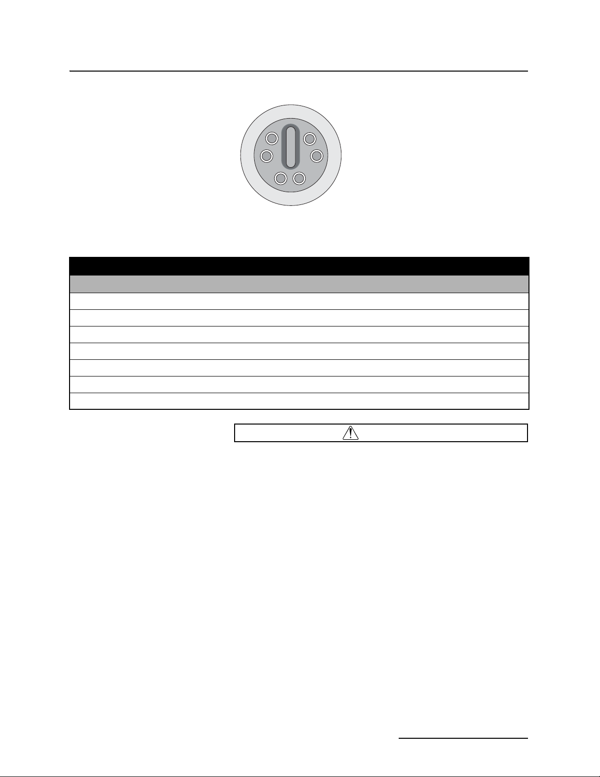
G
F
A
E
D
Communications Port
Figure 1-5 2150EX Area Velocity Flow System Communication Connector Pins
B
C
Table 1-9 Communication Connector Pins
Pin Name Description
A NETA Network differential transceiver Data A
B NETB Network differential transceiver Data B
C VIN+ Positive power supply voltage input (+8 VDC nominal)
D VIN– Negative power supply voltage input (0 VDC nominal)
E RCVUP PC data receiver RS232 compatible input
F XMTUP PC data transmit RS232 compatible output
G Key Aligns connector pins
CAUTION
The connector of the interrogator cable and protective cap both
have an alignment key to ensure proper connection. Observe
proper alignment and NEVER reverse the connector. Even a
momentary pin short can cause permanent damage to the batteries.
1-11
Page 26

2150EX Area Velocity Flow Module
Section 1 Introduction
1-12
Page 27

2150EX Area Velocity Flow Module
Section 2 Preparation and Installation
2.1 Unpacking Instructions
Teledyne Isco, Inc.
Customer Service Dept.
P.O. Box 82531
Lincoln, NE 68501 USA
Phone:(800) 228-4373
Outside USA & Canada
call:
(402) 464-0231
FAX: (402) 465-3022
When the system arrives, inspect the outside packing for any
damage. Then carefully inspect the contents for damage. If there
is damage, contact the delivery company and Teledyne Isco (or its
agent) immediately.
WARNING
If there is any evidence that any items may have been
damaged in shipping, do not attempt to install the unit.
Please contact Teledyne Isco (or its agent) for advice.
When you unpack the system, check the items against the
packing list. If any parts are missing, contact the delivery
company and Teledyne Isco’s Customer Service Department.
When you report missing part(s), please indicate them by part
number. In addition to the main packing list, there may be other
packing lists for various sub-components.
It is recommended that you retain the shipping cartons as they
can be used to ship the unit in the event that it is necessary to
transport the system.
Please complete the registration card and return it to Teledyne
Isco, Inc.
E-mail:
IscoInfo@teledyne.com
2-1
Page 28

2150EX Area Velocity Flow Module
Section 2 Preparation and Installation
2.2 Preparing for Installation
2.2.1 Safety
A 2150EX flow system may be a portable installation, powered
by a 2191EX or 2196EX battery module (described in Section
2.4), or a permanent installation, powered from the safe area by
the 2194EX network interface module (described in Section 2.5).
WARNING
Intrinsic safety is dependent on proper installation in
accordance with IEC 60079-14 and IEC 60079-17
International Standards, or ATEX Group II, Category 1G or
2G requirements of the authority that has jurisdiction for
the installation of equipment in hazardous areas at your
specific installation site. Installation should be performed
only by trained and qualified personnel.
WARNING
Avoid hazardous practices! If you use these instruments in
any way not specified in this manual, the protection
provided by the instruments may be impaired; this will
increase your risk of injury.
WARNING
The installation and use of this product may subject you
to hazardous working conditions that can cause you
serious or fatal injuries. Take any necessary precautions
before entering a worksite. Install and operate this product
in accordance with all applicable safety and health
regulations, and local ordinances.
The 2150EX module components are often installed in confined
spaces. Some examples of confined spaces include manholes,
pipelines, digesters, and storage tanks. These spaces may become
hazardous environments that can prove fatal for those unprepared. In the United States, these spaces are governed by OSHA
1910.146 and require a permit before entering.
Read the Safety section at the front of this manual, and the
general safety information in Appendix E.
2.2.2 Locating the Site The 2150EX is designed to measure flow in open channels with or without a primary device. A primary device is a hydraulic structure, such as a weir or a flume that modifies a channel so there is a known relationship between the liquid level and the flow rate. Although the 2150EX supports flow rate conversion in channels with a primary device, its level and velocity measurement capabilities are best suited for channels without a primary device.
2-2
Page 29

2150EX Area Velocity Flow Module
Section 2 Preparation and Installation
Note
Primary devices limit the usefulness of the AV Sensor’s readings. In most cases, levels and velocities near these structures
do not represent what normally occurs in the channel. If you
must use area velocity flow conversion, or if your interest is the
stream’s velocity, do not install the AV Sensor near a primary
device. Move the AV Sensor away to where the flow is unaffected by the primary device.
2.2.3 Channels Without a
Primary Device
2.2.4 Channels With a
Primary Device
2.2.5 2150EX and AV Sensor
Mounting
Considerations
When the AV Sensor is installed without a primary device, find a
section of channel with a minimum of disturbances to the flow.
Avoid areas with elbows, outfalls, inverts, junctions, etc. that
create turbulence near the AV Sensor. The AV Sensor should be
located away from these disturbances to a point where the flow
has stabilized. For best results, install the AV Sensor where the
flow is most uniform. Uniform flow is a condition where the
water surface is parallel to the bottom of the channel.
If the AV Sensor is installed in a primary device, its location
depends on the type of primary device. Most primary devices
have a specific place for the head (level) measurement sensor. For
more details about the location of the head measuring point,
refer to the Isco Open Channel Flow Measurement Handbook, or
to information provided by the manufacturer of the primary
device.
Note
When you install the AV Sensor for use within a primary
device, a Level-to-Flow conversion method should be used.
(See Programming, Section 3.)
Ideal sites are easily accessible for service and data collection,
while still providing protection for the 2150EX module devices.
The 2150EX module devices are rated NEMA 4X, 6P, and constructed of materials that can withstand harsh environments.
However, continual exposure to UV light, or periodic submersion
should be avoided to extend the life of the components.
Typically, the 2150EX is suspended inside a manhole. Suspending the 2150EX near the opening will protect it from the elements, minimize the chance of submersion, and allow it to be
easily retrieved without entering the manhole.
2-3
Page 30

2150EX Area Velocity Flow Module
Section 2 Preparation and Installation
2.3 Site Examples Figures 2-1, 2-2, and 2-3 illustrate typical round-pipe sites. Key
items are called out in the illustration and explained below.
Figures 2-1 and 2-2 represent portable installations. For
details about portable installations, see Section 2.4.
Figure 2-3 represents a permanent installation. For details
about permanent installations, see Section 2.5.
The computer running Flowlink (Figures 2-1 and 2-3) or the
2101 Field Wizard module (Figure 2-2) should be located
outside the potentially explosive atmosphere. The computer and
modules communicate with the 2150EX module.
The 2150EX area velocity flow module measures and stores
the stream data. In portable installations (Figures 2-1 and 2-2),
it is attached to a 2191EX or 2196EX battery module, which
supplies power to the module.
As described in Section 2.6.1, the EX network cable connects to
the top of the 2150EX stack and extends to the interface of the
safe and hazardous areas.
As described in Section 2.6.2, an RS232EX isolator cable connects the computer and the site. The cable supports the data
transfers between the two, and is connected to an EX Network
Cable connected to the top of the 2150EX module.
As described in Section 2.6.3, an RS485EX isolator cable connects the site with a Field Wizard or other network device. The
cable supports the data transfers between the two, and is connected to an EX Network Cable, connected to the top of the
2150EX module.
In permanent installations (Figure 2-3), the 2150EX is connected
via a network interface cable, usually through conduit, to the
2194EX network module, located in the safe area, which
serves as both power supply and network or PC connection.
The AV2150EX sensor cable must be routed carefully without
kinks, coils, or sharp bends, but may be snake-looped and tied.
Any excess cable must be kept out of the channel to prevent
debris from collecting.
The Mounting Ring holds the AV2150EX sensor in place.
The AV2150EX sensor is positioned in the flow stream to
measure liquid level and velocity.
2-4
Page 31

SAFE AREA
2150EX Area Velocity Flow Module
Section 2 Preparation and Installation
Computer running Flowlink
(Hazardous boundaries are normally
specified by local authorities.)
FLOW
POTENTIALLY
EXPLOSIVE
AREA
RS232EX Isolator Cable
EX Network Cable
2150EX Area Velocity
Flow Module
2191EX or 2196EX Battery
Module
Mounting Ring
AV2150EX Sensor
Figure 2-1 Typical Round-pipe Installation Connected to a
Laptop Computer (Portable Installation, see section 2.4)
2-5
Page 32

2150EX Area Velocity Flow Module
Section 2 Preparation and Installation
(Hazardous boundaries are normally
specified by local authorities.)
FLOW
SAFE AREA
POTENTIALLY
EXPLOSIVE
AREA
2101 Field Wizard Module
RS485EX Isolator Cable
EX Network Cable
2150EX Area Velocity
Flow Module
2191EX or 2196EX Battery
Module
Mounting Ring
AV2150EX Sensor
Figure 2-2 Typical Round-pipe Installation Connected to a
2101 Field Wizard (Portable Installation, see section 2.4)
2-6
Page 33

Equipment Box
2150EX Area Velocity Flow Module
Section 2 Preparation and Installation
(Hazardous boundaries are normally
specified by local authorities.)
Computer running
Flowlink
SAFE AREA
POTENTIALLY EXPLOSIVE AREA
Interrogator Cable
2194EX Network/
Power Module
Isco Power Pack
EX Interface Cable
and Conduit
2150EX Area Velocity
Flow Module
This figure is not intended to
depict the meeting of special
conditions indicated by "X"
markings on the equipment.
Refer to IEC 60079-14 section
12.2.4 regarding intrinsically safe
apparatus that does not
withstand the 500VAC electrical
strength test.
See the warnings below.
FLOW
Figure 2-3 Typical Round-pipe Installation Connected to a
2194EX Module and Laptop
(Permanent Installation, see section 2.5)
Due to the creation of a permanent grounding point between
the sensor’s transducer cover and the mounting ring when
the sensor is installed, the 2150EX system can not
withstand the 500 VAC test according to EN50020:2002
clause 6.4.12. Refer to IEC 60079-14, section 12.2.4,
regarding earthing of intrinsically safe circuits.
Mounting Ring
(See WARNINGS
below.)
AV2150EX Sensor
WARNING
2-7
Page 34

2150EX Area Velocity Flow Module
Section 2 Preparation and Installation
WARNING
The sensor mounting ring is a potential isolated charge
carrier. Your installation MUST satisfy earthing
requirements. Refer to IEC 60079-14 section 12.2.4 and IEC
60079-11.
2.4 Portable Installations For portable installations, the 2150EX module is stacked with a
2191EX or 2196EX battery module. It communicates with a computer or 2100 Series network device via an EX Network Cable
(for potentially explosive atmospheres) and an EX Isolator Cable.
The 2191EX module contains two sealed, replaceable battery
packs for use in gas hazard zones 0, 1, and 2.
The 2196EX is a rechargeable module for use in gas hazard zones
1 and 2. For detailed information about the 2196EX, turn to
section 2.4.6.
2.4.1 Installation Example The following steps may be used as a guide to install a basic, portable 2150EX system, including the 2150EX module, the 2191EX battery module, and an AV2150EX sensor.
1. Prepare the Battery Module.
a. Install the battery packs (See section 2.4.2).
b. Inspect the desiccant (2.4.3).
2. Inspect 2150EX module desiccant (2.4.4).
3. Assemble the system.
a. Install the 2150EX module (2.4.5 and Figure 2-6).
b. Attach the AV2150EX sensor cable to the 2150EX mod-
ule (2.7).
4. Install the AV2150EX sensor in the flow stream (2.7.1).
5. Connect the interrogation cable and connect to the site
with Flowlink software (2.6).
a. Create the site by Quick Connecting to the modules.
b. Set up the site and module settings.
6. Disconnect from the site and replace all protective caps.
2.4.2 Install Battery Module Batteries
2-8
The 2191EX Battery Module requires two LTC2191EX 8 volt
lithium battery packs (P/N 68-2000-022) or two SLA2191EX 8
volt lead-acid battery packs (P/N 68-2000-023). These packs are
sealed and explosion protected, so they can be safely installed in
a potentially explosive atmosphere.
WARNING
Substitution of components will impair intrinsic safety.
Page 35

Figure 2-4 Illustration of Battery Packs
2150EX Area Velocity Flow Module
Section 2 Preparation and Installation
Battery Pack
Door
Figure 2-5 Label Markings for LTC2191EX and SLA2191EX Battery Packs
CAUTION
To avoid overloading the fuses in the LTC2191EX lithium battery packs, disconnect the 2150EX module(s) before installing
or replacing the lithium battery packs. The SLA2191EX
lead-acid battery packs do not contain fuses, and do not
require that the 2150EX module(s) be disconnected.
2-9
Page 36

2150EX Area Velocity Flow Module
Section 2 Preparation and Installation
If you are installing the LTC2191EX lithium battery packs, first
disconnect the 2150EX module(s). If you are installing the
SLA2191EX lead-acid battery packs, it is not necessary to disconnect the 2150EX module(s). Then:
Repeat steps 1 through 4 to install the second battery pack.
When finished, reconnect the 2150EX module(s).
1. Remove the battery door. To remove the door, turn it
1
/4 turn
counter-clockwise and pull it from the Battery Module.
2. Align the connectors and insert the new battery pack into
the Battery Module.
3. Check the humidity indicator disk inside the door. (See section 2.4.3.)
4. Replace the door. Align the small triangle on the door with
the triangle above the battery port, push inward, and
rotate
1
/4 turn clockwise so the curved arrow is at the top of
the door.
Note
The battery packs should always be replaced as a pair. Never
mix old and new batteries. Battery packs should be disposed
of according to local battery disposal regulations. The
lead-acid battery packs should be recharged or recycled.
2.4.3 Inspect the Desiccant –
Battery Module
30
20
40
Humididy indicator
2.4.4 Inspect the Desiccant –
2150EX Module
A humidity indicator is mounted inside each battery cap on the
Battery Module. The humidity indicators have regions that
display 20, 30, and 40 percent humidity levels. Ideally each
region should be completely blue. As the desiccant becomes saturated, the humidity levels will increase and the regions turn
pink. When the 40 percent region turns pink, the Battery Module
is no longer adequately protected and the desiccant must be
replaced. Refer to section 5.4 for replacement instructions.
A desiccant cartridge is inserted into the side of the 2150EX
Module. The cartridge is filled with silica gel beads that will
indicate when they are saturated. When dry, the beads are blue
or yellow. As the desiccant becomes saturated, the humidity
levels will increase and the beads turn pink or green. If the
entire length of the desiccant cartridge turns pink or green, the
reference air is no longer adequately protected and the desiccant
must be replaced. Refer to section 5.4 for replacement instructions.
CAUTION
Operating the 2150EX and sensor with saturated desiccant
can cause many problems such as drifting level readings and
permanent damage. It is important that the equipment is serviced often enough to prevent the entire desiccant cartridge
from becoming saturated.
2-10
Page 37

2150EX Area Velocity Flow Module
Section 2 Preparation and Installation
2.4.5 Assembling the System The 2100 Series System is modular; you build the system by con-
necting modules together. The instructions in this section
describe how to connect a 2150EX module to a 2191EX or
2196EX battery module in its most basic configuration — by
stacking the two modules. The battery module must be at the
bottom of the stack.
You can use multiple modules in a stack to increase the site’s
functions. A maximum of two 2150EX modules may be powered
by one battery module, to avoid overloading the batteries.
However, within a stack, you can have multiple sets of
2150EX/2191EX combinations.
Connection options Keep in mind that stacking is not the only way to connect
modules. The modules may be placed in remote locations and still
operate as a single site. If you would like to use remote modules
for your application, please consult with the factory or your representative to realize the full potential of your system.
Figure 2-6 Assembling a basic portable system
Connecting the Modules To connect the 2150EX and 2191EX/2196EX modules, refer to
the following instructions and Figure 2-6.
1. On the top of the battery module, remove the cap and stow
it on the holder. This exposes the communication connector.
2. Prepare the battery module’s communication connector:
a. Inspect the connector. It should be clean and dry. Dam-
aged O-rings must be replaced. Spare O-rings (P/N
202-1006-69) are supplied in the 2191EX maintenance
kit (60-2009-332).
2-11
Page 38

2150EX Area Velocity Flow Module
Section 2 Preparation and Installation
The communications indicator will blink during the start-up
routine to indicate the 2150EX is operating.
b. Coat the O-ring’s sealing surface with a silicone lubri-
cant. (A small quantity of lubricant is supplied in the
maintenance kit.)
CAUTION
Do not use petroleum-based lubricants. Petroleum-based
lubricants will cause the O-ring to swell and eventually deteriorate. Aerosol silicone lubricant sprays often use petroleum
based propellants. If you are using an aerosol spray, allow a
few minutes for the propellant to evaporate before proceeding.
3. Place the carrying handle on the battery module. (If you
are stacking two 2150EX modules on top of the
2191EX/2196EX, position the handle between the 2150EX
modules.)
4. Unlock the 2150EX module’s latch by pressing in on the
latch release (right side).
5. Underneath the 2150EX, remove the cap from the lower
communication connector and stow it in the holder.
6. Lock the latch. Locking the latch correctly seats and aligns
the lower cap in its holder.
7. Position the 2150EX over the 2191EX/2196EX battery
module. Align the connectors and lower the 2150EX onto
the 2191EX/2196EX.
8. Unlock the 2150EX module’s latch by pressing in on the
latch release (right side).
9. Firmly press the modules together and lock the 2150EX
module’s latch (left side).
2-12
Note
Unused communication ports on the top and bottom of the
stack must be capped. The connector caps terminate the communication lines and protect the pins.
Page 39

2150EX Area Velocity Flow Module
Section 2 Preparation and Installation
2.4.6 Zone 1 Battery Module The Model 2196EX is a rechargeable battery module for zones 1 and 2 that offers indication of declining voltage prior to power interruption, with two batteries permanently contained in an IP68 enclosure. See Figure 2-10 for X marking and port labeling. The 2196EX may be safely connected to or disconnected from a 2150EX flow module within a hazardous area.
Note
The 2196EX is for use in gas hazard zones 1 and 2. It is not
approved for use in zone 0 installations, in accordance with
IEC 60079-14.
The 2196EX module has no port or latches on the bottom of the
case; therefore, it can only be installed on the bottom of a module
stack. One 2196EX module can power one or two 2150EX flow
modules with sensors attached.
The 2196EX uses two fully rechargeable, nonreplaceable
lead-acid batteries.
Never operate or store the 2196EX at temperatures above 140 °F
(60 °C). Operate the 2196EX below 86 °F (30 °C) for maximum
service life. For prolonged shelf life, the 2196EX should be stored
at 50 °F (10 °C) or lower in a fully charged state.
Battery protection The module protects the lead-acid batteries from damage due to
deep discharge by first indicating critically low voltage through
Flowlink software, and then by shutting off when the voltage
becomes critically low.
–
+
2196EX port connector
As the 2196EX output voltage decreases to a value near the
7-volt shut-off threshold, Flowlink software will issue a
low-voltage warning (Figure 2-7).
Neither of these protective functions should become necessary on a regular basis. Check the battery voltage
reading regularly, according to your specific application,
and recharge the batteries before the warning appears.
The voltage may also be tested with a voltmeter at the port connector on pins c (+) and d (–), or on the internal circuit board (see
the test points shown in Figure 2-8).
Note
There is a 60K ohm resistor in series with the voltage sensing
circuit. The voltage reading measured on the circuit board may
have slight variance, depending on the voltmeter used.
2-13
Page 40

2150EX Area Velocity Flow Module
Section 2 Preparation and Installation
Figure 2-7 Flowlink low-voltage warning
A 2196EX module kept in storage for extended periods should
be recharged approximately every six to nine months. The battery voltage should never be allowed to fall below 10.5 volts
before recharging. Deep discharge of the lead-acid batteries
can lead to permanent loss of capacity.
CAUTION
Charging The 2196EX module requires a lead-acid battery charger with a
maximum rating of 20 volts, 2 amps. The module is fused for protection against excessive current (see Figure 2-9).
WARNING
Do not charge the 2196EX in a potentially explosive
environment. Charge only in a safe area.
WARNING
When charging the 2196EX, observe maximum voltage
ratings of Um = 250V and Un = 20V. The charger output must
not exceed 20 volts or 2 amperes as labeled.
In order to recharge the batteries, the 2196EX module case must
be opened. Unlike other 2100 modules, which have two desiccant
holders, the 2196EX has only one, located on the inside of the
right compartment door.
Note
During the charging process, the 2196EX case must remain
open, exposing the desiccant to the atmosphere. Teledyne
Isco recommends storing the desiccant in an airtight container
while charging the batteries. Check the humidity indicator on
the inside of the door whenever it is opened and ensure that
only dry desiccant is installed when re-sealing the case.
2-14
Page 41

Rechargeable, non-
replaceable lead-acid
batteries
2150EX Area Velocity Flow Module
Section 2 Preparation and Installation
The charging terminals are located on the circuit board mounted
on the inside of the left compartment door (Figures 2-8 and 2-9, +
and –). A cable ending in alligator clips may be connected to these
terminals for charging.
CAUTION
The circuit board is permanently connected to the interior of
the module. Use care when opening the case that the wires
are not damaged.
During charging, the yellow LED on the circuit board remains on
to indicate charge voltage in correct polarity. The replaceable 2A
fuse on the back side of the board protects against excessive
current.
Charge terminals
(remove screws to
access fuse)
–
+
Figure 2-8 Location of 2196EX charging terminals
Desiccant holder
(remove screws to
access desiccant
2-15
Page 42

2150EX Area Velocity Flow Module
Section 2 Preparation and Installation
Measure the voltage between
Test Point 1 and H5 (negative
terminal).
BATTERY VOLTS (TP1)
MAXIMUM 50 CELSIUS
NEVER
CHARGE IN
POTENTIALLY
EXPLOSIVE ENVIRONMENT
(-) NEGATIVE (+) POSITIVE
FUSED
INPUT
VOLTAGE
(LED)
AMBIENT DURING CHARGE
MAXIMUM CHARGER RATING
20 VOLTS 2 AMPERES
Um = 250V
Un = 20V
2A replaceable fuse
H19
Front
There is a 60K ohm resistor in series with the voltage sensing
circuit. The voltage reading measured on the circuit board may
have slight variance, depending on the voltmeter used.
Figure 2-9 Detailed view of charging circuit board
Fuse replacement To access the 2A charge fuse (F1), remove the two mounting
screws holding the circuit board inside the compartment lid.
Replace the fuse with the specified Littlefuse 216002 or
Cooper/Bussman S501 only (Isco part #411-9922-60).
Charger options See Appendix B for part numbers and ordering infor-
mation.
The 2196EX can be charged using the Isco Model 965 five-station
battery charger, or the Isco Model 963 desktop charger. The 965
has five 2-pin amphenol connectors on the front. The 963 has a
single, 2-pin amphenol cable. Both chargers require an adaptor
cable for use with the 2196EX (Isco part #60-1394-023), and are
user-switched for 120/240VAC, 50/60Hz applications.
The 965 provides greater charging voltage, and can therefore
charge to a higher capacity than the other chargers offered.
However, because of this, the module should not remain connected to it beyond the charging period.
Back
2-16
CAUTION
The module should not remain connected to the Isco Model
965 charger after the Battery Voltage measured at TP1
reaches 13.8 volts. Over time, overcharging can decrease the
water content of the batteries’ electrolyte, causing premature
aging.
Page 43

Important Information
Regarding "X" Marking
2150EX Area Velocity Flow Module
Section 2 Preparation and Installation
The 963 is a float mode charger, using a lower voltage, which
reduces the risk of overcharging. It can fully charge the module
in 16-24 hours maximum.
Teledyne Isco also offers a 2-Amp charger that includes a connect
cable ending in alligator clips, indicator lights for maximum
output and float voltage, and protection against reverse polarity.
It can charge the 2196EX to in about 6 hours. The charger is compatible with 125/240 VAC input.
The ATEX labeling on the serial tag of the 2196EX module shows
a number ending in "X". The X marking indicates that there are
special conditions that must be met to ensure safety, as explained
on page vi in the front of this manual.
WARNING
Ensure that the 2196EX module case is never subjected to
physical impact with enough force to cause cracking during
transport, installation, operation, or storage. Damage to the
case can compromise the unit’s safety.
Figure 2-10 2196EX battery module and labeling
Refer to page vi regarding "X" marking on labels.
2-17
Page 44
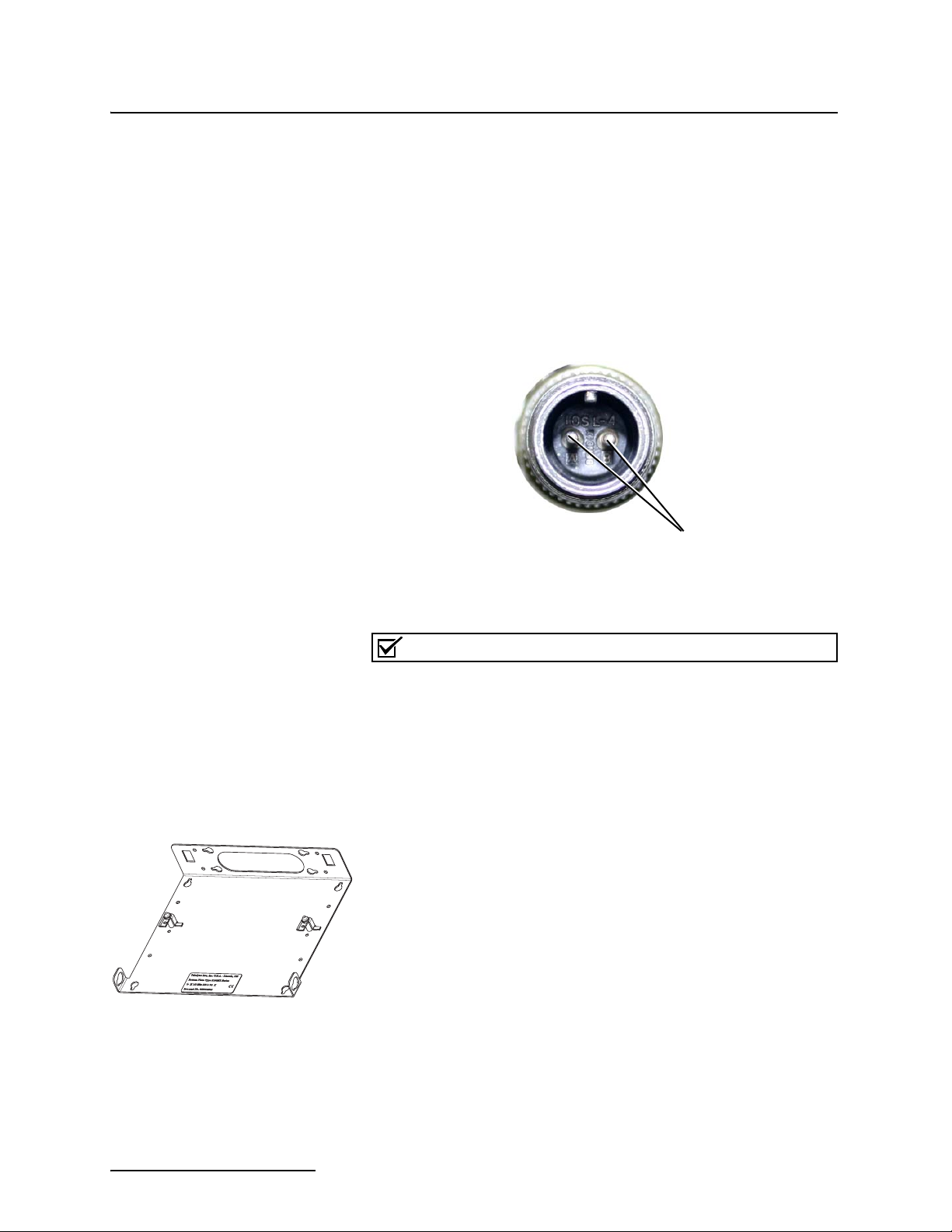
2150EX Area Velocity Flow Module
Section 2 Preparation and Installation
2.5 Permanent Installations
Figure 2-11 Amphenol connector pins for 12V adapter
cable 69-2004-451
For permanent installations, the 2150EX can be powered from a
safe area by an associated apparatus, the 2194EX module. The
2194EX also serves as a network interface, with network and
RS232 communication via the top connector. The 2194EX
requires 12 or 24 volts DC, and may be powered by an Isco
910/920 series power pack, 934 NiCad battery, or 940 series lead
acid battery using power adapter cable 69-2004-451. For details
about these power supplies, see Isco’s Power Products Guide
(60-9003-092).
Pin B = +12 Volts
Pin A = Neutral
EX Bottom Plate
60-2004-344
Note
Isco AC power supplies do not provide galvanic isolation in
accordance with IEC 60079-14 for Zone 0 installations.
Connection to the 2194EX module requires the network interface
cable. The cable’s molded connector plug will connect to the
bottom communication port of the 2150EX module. The other end
will enter the safe area, usually via conduit.
Make sure the 2150EX is secured so that it will not accidentally
fall or be swept away by flooding. Mount the 2150EX onto the EX
bottom plate (60-2004-344) for suspension over the flow stream.
Use the notched holes in the plate to insert fasteners to secure
the module to a wall, or attach a carrying handle and suspension
handle (P/N 69-2003-271 and P/N 60-1704-017), which can be
secured to a ladder rung.
Two interface cable assemblies are available from Teledyne Isco:
75m (60-2004-337) and 150m (60-2004-338). You must cut the
cable to the appropriate length and wire it to the socket insert of
the 2194EX’s J1 interface connector (Figures 2-12 and 2-15),
which is clearly marked with the proper entity parameters. To
power one 2150EX module, the cable must be 150 meters or
shorter. To power two 2150EX modules, the cable must be 75
meters or shorter.
2-18
Page 45
2150EX Area Velocity Flow Module
Section 2 Preparation and Installation
Observe intrinsic safety requirements regarding proximity to
external sources of potential electric or magnetic interference.
Refer to IEC 10079-14 section 12.2.2.5 on installation of cables
and wiring.
WARNING
Do not coil the interface cable; this will form an inductor
and create a hazard. The cable should be kept as short as
is practical.
Teledyne Isco strongly recommends that you route the
interface cable through conduit between the safe and hazardous areas. Two different sizes of conduit fittings are pro-
vided with the interface cable assembly (Figure 2-14).
2.5.1 Installation Example The following steps may be used as a summary guide to install a basic, permanent 2150EX system, including the 2150EX module, the 2194EX power module, and an AV2150EX sensor. The setup will look similar to Figure 2-3.
1. Inspect 2150EX and 2194EX module desiccant (2.4.4).
2. Install the interface cable.
Important Information
Regarding "X" Marking
WARNING
Do not coil the cable; this will form an inductor and create
a hazard. The cable should be kept as short as is practical.
3. Assemble the system.
a. Install the 2150EX module.
b. Install the 2194EX module in the safe area.
c. Attach the AV2150EX sensor cable to the 2150EX mod-
ule (2.7).
4. Install the AV2150EX sensor in the flow stream (2.7.1).
5. Connect the interface cable between the 2150EX and
2194EX.
6. Connect the interrogation cable to the 2194EX and connect
to the site with Flowlink software.
a. Create the site by Quick Connecting to the modules.
b. Set up the site and module settings.
c. Disconnect from the site and replace all protective caps.
The ATEX labeling on the serial tag of the 2194EX module shows
a number ending in "X". The X marking indicates that there are
special conditions that must be met to ensure intrinsic safety, as
explained on page vi in the front of this manual.
In the case of the 2194EX, this associated apparatus does not
provide the galvanic isolation required for zone 0 installations in
accordance with IEC 60079-14 (refer to IEC 60079-14 sections
dealing with earthing of intrinsically safe circuits and installations for zone 0) when powered by an Isco AC power source.
2-19
Page 46

2150EX Area Velocity Flow Module
Section 2 Preparation and Installation
2194EX
Network
Connector
%8.%47/2+
0/24*
5O6
)O!
0O7
#OU&
,OUH
,O2O
U(OHM
Figure 2-12 2194EX labels and cable connector
Locking
ring
Socket
insert
Locking
cap
Main
body
Gland
Refer to page vi regarding "X" marking on labels.
Gland
cage
Gland nut
(When using conduit,
replace with appropriate
conduit fitting.)
Figure 2-13 Network cable connector and wiring
2-20
).42).3)#!,,93!&%#)2#5)4
#/..%#4/2
&,%8#!",%-/5.4
4ELEDYNE)SCO)NC
0ART.O
-ATEFOR#!",%!339
0ART.O
0ART.O
7()4%/2!.'%
/2!.'%7()4%
7()4%'2%%.
#ABLE
'2%%.7()4%
7()4%",5%
",5%7()4%
$2!).
0IN
Page 47

Figure 2-14 Network cable conduit fittings
2150EX Area Velocity Flow Module
Section 2 Preparation and Installation
1/2” NPT (20MM)
Thread
1” NPT (32MM)
Thread
Figure 2-15 Wiring the socket insert
2.6 Network Communication
WHT/GRN
1
GRN/WHT
6
ORN/WHT
5
WHT/ORN
7
Drain
4
BLU/WHT
2
WHT/BLU
3
To connect the 2150EX for network communication, one or two of
three different cables are required, depending on the type of communication, whether the installation is portable or permanent,
and whether or not the flow module installation is in a hazardous
area.
2-21
Page 48

2150EX Area Velocity Flow Module
Section 2 Preparation and Installation
2.6.1 EX Network Cable The EX Network cable (2m P/N 60-2004-335, 8m P/N 60-2004-336) connects to the top of the 2150EX stack and extends to the interface of the safe and hazardous areas, where the actual isolation is located.
Connects to a 2150EX
Connects to an
RS232EX or
RS485EX
Isolator Cable
Figure 2-16 EX Network Cable for Connection to an Isolator Cable
To connect the EX Network and RS232EX isolator cables:
1. Remove the protective cap from the communication
connector on the top of the 2150EX module.
2. Store the protective cap in the holder next to the connector.
3. Push the 6-pin end of the EX Network cable onto the communication connector on the top of the 2150EX module.
Use care, so you do not misalign the pins and cause
any short circuits.
4. Route the cable as shown in Figure 2-1, so the other end of
the EX Network cable is at the interface of the safe and
hazardous areas.
5. Attach the hazardous area end of the RS232EX isolator
cable to the EX Network cable coming from the 2150EX.
Use care, so you do not misalign the pins and cause any
short circuits! Attach the other end of the RS232EX cable
to the appropriate port on your computer.
Note
You can safely connect and disconnect the RS232EX cable
from the EX Network cable without removing the 2150EX module or the EX Network cable from the potentially explosive
atmosphere.
2-22
When the communication connector is not in use, it should
always be capped to prevent corrosion and improve communications. When the communication connector is in use, store the cap
on the holder next to the connector.
Page 49

2150EX Area Velocity Flow Module
Section 2 Preparation and Installation
CAUTION
Caps PUSH ON and PULL OFF. Do not rotate the caps to
remove them from the connectors.
2.6.2 Connecting to a Computer for Interrogation
The 2150EX module can be connected to a computer located in a
safe area, using Isco’s Flowlink software (see Figure 2-1). In
order for the 2150EX to communicate with a computer, the two
must be connected by an Isco RS232EX Isolator Cable (P/N
60-2004-339). The hazardous area end, labeled with proper
entity parameters, connects to the EX Network cable. This
enables you to update the 2150EX’s software without entering
the potentially explosive atmosphere.
Observe intrinsic safety requirements regarding proximity to
external sources of potential electric or magnetic interference.
Refer to IEC 10079-14 section 12.2.2.5 on installation of cables
and wiring.
If the 2150EX and AV 2150EX sensor are not located in a potentially explosive atmosphere, the RS232EX isolator cable can be
connected directly to the top of the 2150EX.
RATED INPUT
25V 1/2A
EIA-RS232
connects to computer using maximum 250V (Um =
250V)
Pin 2 Transmit Data
Pin 3 Receive Data
Pin 4 Requires 3 - 15V
Pin 5 Power/Signal Ground
Pin 7 Requires 3 - 15V
Safe Area End
12345
6
89
7
Figure 2-17 RS232EX Isolator Cable for Connection to a Computer
2.6.3 Connecting to a 2100 Series Network Device
The 2150EX can be connected to a 2100 Series network device
located in a safe area (with the exception of the 2102 Wireless
module). In order for the 2150EX to communicate with a 2100
Label marking for the
RS232EX Isolator
Cable
Hazardous Area End
Ui = 9.282V
I i = 4.000A
Pi = 4.000W
Ci = 2.827uF
Li = 0.000uH
connects to an
EX Network Cable
(P/N 60-2004-336)
2-23
Page 50

2150EX Area Velocity Flow Module
Section 2 Preparation and Installation
Series network device other than the 2194EX, the two must be
connected by an Isco RS485EX Isolator Cable (P/N 60-2004-340).
The hazardous area end, labeled with proper entity parameters,
connects to the EX Network cable.
Observe intrinsic safety requirements regarding proximity to
external sources of potential electric or magnetic interference.
Refer to IEC 10079-14 section 12.2.2.5 on installation of cables
and wiring.
If the 2150EX and AV2150EX sensor are not located in a potentially explosive atmosphere, the RS485EX isolator cable can be
connected directly to the top of the 2150EX.
A site example using the Field Wizard is shown in Figure 2-2.
Label marking
for the RS485EX
Isolator Cable
Hazardous Area End
connects to an
EX Network Cable
(P/N 60-2004-336)
Safe Area End
RATED INPUT
16.6V 10A
EIA-RS485
connects to Field Wizard
or other network device
using maximum 250V
(Um = 250V)
Ui = 9.282V
I i = 4.000A
Pi = 4.000W
Ci = 1.650uF
Li = 0.000uH
Figure 2-18 RS485EX Isolator Cable for Connection to a 2100 Series Network Device
To connect the EX Network and RS485EX isolator cables:
1. Remove the protective cap from the communication
connector on the top of the 2150EX module.
2. Store the protective cap in the holder next to the connector.
3. Push the 6-pin end of the EX Network cable onto the communication connector on the top of the 2150EX module.
2-24
Page 51

2150EX Area Velocity Flow Module
Section 2 Preparation and Installation
Use care, so you do not misalign the pins and cause any
short circuits!
4. Route the cable as shown in Figure 2-2, so the other end of
the EX Network cable is at the interface of the safe and
hazardous areas.
5. Attach the hazardous area end (with yellow/blue label) of
the RS485EX cable to the EX Network cable coming from
the 2150EX. Use care, so you do not misalign the pins and
cause any short circuits! Attach the other end of the
RS485EX cable to the communication connector on the
power supply for the Field Wizard or other network device.
Note
You can safely connect and disconnect the RS485EX cable
from the EX Network cable without removing the 2150EX module from the potentially explosive atmosphere.
When the communication connector is not in use, it should
always be capped to prevent corrosion and improve communications. When the communication connector is in use, store the cap
on the holder next to the connector.
2.7 Connecting the AV2150EX Sensor
Note
Caps PUSH ON and PULL OFF. Do not rotate the caps to
remove them from the connectors.
The AV2150EX sensor cable attaches to the sensor receptacle on
the 2150EX module.
To connect the AV Sensor (refer to Figure 2-19):
1. Remove the protective caps:
a. On the 2150EX, push down on the sensor release while
pulling the protective cap from the receptacle.
b. On the AV Sensor cable, pull the cap from the end of its
connector.
2. Prepare the AV Sensor connector:
a. Inspect the connector. It should be clean and dry. Dam-
aged O-rings must be replaced. Spare O-rings (P/N
202-1006-69) are supplied in the 2150EX maintenance
kit (60-2059-001).
b. Coat the O-ring’s sealing surface with a silicone lubri-
cant.
CAUTION
Do not use petroleum-based lubricants. Petroleum-based
lubricants will cause the O-ring to swell and eventually deteriorate. Aerosol silicone lubricant sprays often use petroleum
based propellants. If you are using an aerosol spray, allow a
few minutes for the propellant to evaporate before proceeding.
2-25
Page 52

2150EX Area Velocity Flow Module
Section 2 Preparation and Installation
Figure 2-19 Connecting the AV Sensor
Important Information
Regarding "X" Marking
The ATEX labeling on the sensor’s serial tag shows a number
ending in "X". The X marking indicates that there are special
conditions that must be met to ensure safety, as explained on
page vi in the front of this manual.
Sensor Release
Caps
3. Align and insert the connector. The sensor release will click
when the sensor connector is fully seated.
4. Connect the two caps together.
The AV2150EX sensor is labeled and X-marked for special
usage conditions in order to prevent static electricity. Avoid
conditions that may generate a static charge, such as rubbing
the AV2150EX with static producing cloth.
Figure 2-20 AV2150EX Sensor Cable Labels
CAUTION
WARNING
ELECTROSTATIC HAZARD
DO NOT RUB
CLEAN WITH DAMP CLOTH ONLY
X-Marking
2-26
Page 53

2150EX Area Velocity Flow Module
Section 2 Preparation and Installation
2.7.1 Positioning the AV Sensor
Ideal Conditions - Uniform Flow
Poor Conditions
Sensor installation is discussed in Section 2.8 of this manual.
Consult your Isco Mounting Rings instruction manual for
detailed hardware information. This section explains how to
position the AV Sensor in flow streams.
Several factors concerning the AV Sensor’s installation may
affect your system’s performance. Review the following to understand how to obtain the best results:
Uniform flow - The AV Sensor provides the best results in flow
streams with uniform flow. An example of uniform flow is shown
in the margin.
Avoid poor channel conditions - Poor channel conditions may
cause incorrect or erratic readings. Areas to avoid are:
• outfalls or channel intersections
• flow streams at very low levels with high flow rates
• turbulence
• channel sections that are apt to collect debris or silt
• depths that consistently run below 2.54 cm (1 inch).
Install the AV Sensor in streams where the liquid covers the
sensor. The AV Sensor can detect levels above approximately
1.0 cm (0.4 inch) and typically can measure velocities in streams
as low as 2.54 cm (1 inch). Streams that run consistently below
2.54 cm are not a good application for the 2150EX.
The example in the margin shows an illustration of these poor
conditions. The outfall is drawing down the liquid level and the
AV Sensor is disturbing the flow. In this example, the AV Sensor
should be moved forward to avoid the drawdown near the outfall.
Offsets - You can install the AV Sensor above the bottom of the
flow stream or along the side of the channel, as long as it will be
continually submerged. The 2150EX can be adjusted to measure
level with the AV Sensor at nearly any depth. The AV Sensor
cannot, of course, measure a liquid level that falls below its
position in the flow stream.
Installing the AV Sensor above the bottom has advantages:
• It avoids heavy concentrations of silt, sand, or other solids.
• It aids installation in narrow or hard-to-reach locations.
• It maximizes level resolution over a specific level range.
• It can avoid obstructions in the flow stream.
When the AV Sensor is installed above the bottom of the channel,
a Zero Level Offset must be entered in the program settings (see
Section 3.3.2).
Liquid properties - Velocity measurements depend on the
presence of some particles in the stream such as suspended
solids or air bubbles. If the stream lacks particles it may be necessary to aerate the water upstream from the sensor.
2-27
Page 54

2150EX Area Velocity Flow Module
Section 2 Preparation and Installation
Handle with care - Abusive handling will damage the AV
Sensor. Although the AV Sensor will survive normal handling
and installation, treat the sensor with reasonable care. The
internal components cannot be repaired.
Secure the cable - We recommend that you secure the cable in
place. Tying off the cable can often prevent lost equipment if
excessive flow dislodges the sensor and its mounting.
CAUTION
The vent tube inside the sensor cable must remain open. Do
not kink the cable or overtighten the plastic ties while securing
the cable.
WARNING
Do not coil the sensor cable. This will form an inductor and
create a hazard.
2.8 Mounting Rings Consult your Isco Mounting Rings instruction manual for
detailed hardware information.
The following sections describe sensor installation using the two
options available for mounting the AV sensor in pipes or
round-bottomed flow streams. For pipes up to 15" (38 cm) in
diameter, stainless steel self-expanding mounting rings
(Spring Rings) are available. For pipes larger than 15" in
diameter, Teledyne Isco offers the Scissors Rings (Universal
Mounting Rings). Area velocity sensors can also be installed
using primary measuring devices.
WARNING
Due to the creation of a permanent grounding point
between the sensor’s transducer cover and the mounting
ring when the sensor is installed, the 2150EX system can
not withstand the 500 VAC test according to EN50020:2002
clause 6.4.12. Refer to IEC 60079-14, section 12.2.4,
regarding earthing of intrinsically safe circuits.
WARNING
The sensor mounting ring is a potential isolated charge
carrier. Your installation MUST satisfy earthing
requirements. Refer to IEC 60079-14 section 12.2.4 and IEC
60079-11.
2-28
Page 55

2150EX Area Velocity Flow Module
Section 2 Preparation and Installation
2.8.1 Spring Rings To install a spring ring, compress the ring, slip it inside the pipe,
and then allow it to spring out to contact the inside diameter of
the pipe. The inherent outward spring force of the ring firmly
secures it in place. A typical self-expanding mounting ring (with
a probe mounted on it) is shown in Figure 2-21.
These mounting rings are available for use in pipes with inside
diameters of 15.2 cm (6"), 20.3 cm (8"), 25.4 cm (10"), 30.5 cm
(12"), and 38.1 cm (15"). The Isco part numbers for the various
size mounting rings available are listed in Appendix B. These
part numbers include not only the ring, but also the miscellaneous hardware necessary to mount the sensor on the ring.
CAUTION
Always wear leather gloves when handling the rings (either
type). The metal is finished, but there is still a possibility of cutting your hands on the edges.
Compress ring into gap to install in pipe, then...
...outward force of ring against pipe wall holds
ring in place inside pipe.
Figure 2-21 Sensor Installed on a Spring Ring
Attaching the Sensor to the
Ring
Attach the AV sensor to the ring either by using two 4-40 countersink screws or by snapping the optional probe carrier to the
ring. This second method of attaching the sensor allows for easy
removal in case service is needed later.
2-29
Page 56

2150EX Area Velocity Flow Module
Section 2 Preparation and Installation
To complete the sensor-spring ring assembly procedure, attach
the sensor cable to the downstream edge of the ring. Follow the
cable routing shown in Figure 2-21. Other routing directions may
affect measurement accuracy. The cable can actually create a
stilling well downstream from the sensor, causing the level to
read low. Use the self-locking plastic ties supplied with the ring.
Install the ring in the pipe by compressing it. Press inward on
both sides and slide the ring into the pipe.
Route the sensor cable out of the stream and secure it in position
by placing the ties through the holes in the mounting ring and
then locking them around the cable, as shown in figure 2-21.
CAUTION
Make sure the slots on the AV sensor carrier are completely
pressed into the tabs on the ring. This is particularly important
where there is any possibility of reverse flows, or where flows
are of high velocity. If the AV sensor is not fully pressed into the
mounting ring tabs, it might come loose in the stream, and
could possibly be damaged or lost.
Make sure the sensor cable is securely fastened along the
back (downstream) edge of the ring. Otherwise, the sensor
may provide inaccurate level readings under conditions of
high velocity.
2.8.2 Scissors Mounting Ring
CAUTION
Do not overtighten the plastic cable ties; they should be tightened just enough to secure the cable in place, without greatly
indenting the cable. Overtightening the plastic ties may collapse the reference tube in the cable, blocking it.
The spring ring may need anchoring. Under conditions of high
velocity (greater than 1.5 meters per second or 5 feet per second),
the ring may not have sufficient outward spring force to
maintain a tight fit inside the pipe. The ring may start to lift off
the bottom of the pipe, or may even be carried downstream.
This problem is more prevalent in the larger diameter pipes and
in pipes with smooth inside surfaces, such as plastic pipes. If any
of these conditions are present, or if movement of the mounting
ring is detected or suspected, you must anchor the ring in place.
You can do this by setting screws through the ring into the pipe,
or by other appropriate means. If there is a problem with the
smaller diameter rings, it may be sufficient to simply increase
the outward spring force of the ring by bending it into a less
round configuration.
For pipes larger than 15" in diameter, Teledyne Isco offers the
adjustable Scissors Ring (also known as the Universal Mounting
Ring). This device consists of two or more metal strips that lock
together with tabs to form a single assembly. There is a base
section where the sensors are mounted, two or more extension
sections (usually), and a scissors section at the top that expands
2-30
Page 57

2150EX Area Velocity Flow Module
Section 2 Preparation and Installation
the entire assembly and tightens it inside the pipe. The scissors
section contains a long bolt that increases the length of the
section as it is tightened.
The assembled scissors rings fit pipe diameters from 16" to 80".
Secure the unit in place by tightening the scissors mechanism
with a
.040" thick half-hard 301 stainless steel sheet. All other parts are
also stainless steel, except for the plastic cable ties in the
hardware kit.
Each extension, 1, 2, 3, and 4, adds 9.0", 21.5", 31.5", or 41.5",
respectively, to the circumference of the ring. Used alone, the
base section fits a pipe that is approximately 16" to 19" in
diameter. The 9.0" (smallest) extensions can be used to take up or
remove slack, to bring the scissors mechanism into a position
where it can be effectively tightened.
5
/8" socket wrench or other suitable tool. Ring sections are
Note
The hardware kit includes flat head bolts and nuts.Teledyne
Isco strongly recommends bolting the assembled scissors ring
together before installation, using the holes provided for that
purpose. Bolting the tongue sections together can greatly
increase safety and prevent the assembly from being torn
apart.
Do not overtighten the mechanism. It is designed to flex
somewhat to provide a positive lock, once moderately tightened.
For installations in larger channels and/or high flow, extensions
2, 3, and 4 have slots for attaching the ring to the channel wall
using appropriate anchoring hardware.
WARNING
Avoid prolonged use of excessive force when adjusting the
equipment. This can create hot surfaces from the friction
of screw or lever mechanisms, resulting in a potential
ignition hazard if surface temperatures exceed the
equipment’s 135°C rating.
2-31
Page 58

2150EX Area Velocity Flow Module
Section 2 Preparation and Installation
Base Section Tightening the scissors assembly expands the ring to
Scissors Assembly
Extensions
press firmly against the pipe wall, securing the ring.
Figure 2-22 Scissors Ring adjustment
2.8.3 Completing the AV Sensor Installation
To prevent debris from catching on the probe cable, it is
important to attach the cable to the mounting ring so it offers as
little resistance to the flow as possible. Attach the sensor cable to
the downstream edge of the ring, using the self-locking plastic
ties supplied with the ring. Place the ties through the holes in the
mounting ring and then lock them around the cable.
CAUTION
Do not overtighten the plastic cable ties; they should be tightened just enough to secure the cable in place, without greatly
indenting the cable. Overtightening the plastic ties may collapse the reference tube in the cable, blocking it.
The AV sensor installation is finished by securing any excess
sensor cable using cable clamps or other means.
The reference tube inside the cable can be restricted or blocked if
the cable is kinked, sharply bent, coiled, or otherwise pinched.
The sensor cable should be handled and mounted with care. Also,
if there is any appreciable distance between the point where the
sensor cable leaves the mounting apparatus and the location of
the flow meter, be sure to attach the cable to the flow stream wall
to prevent it from vibrating, moving around, tangling, or possibly
collecting debris.
2-32
WARNING
Do not coil the sensor cable. This will form an inductor and
create hazard.
Page 59

2150EX Area Velocity Flow Module
Section 2 Preparation and Installation
CAUTION
Under no circumstances should you leave any extra length of
sensor cable dangling freely in the flow stream where it could
trap debris or become tangled.
Use gloves and eye protection when assembling and installing
the rings in a pipe. Though deburred, the edges of the stainless steel can cut if improperly handled. Please read the infor-
mation on how best to install this device.
Observe general safety procedures when entering any manhole. See “General Safety Procedures” in the back of the manual for more information on general hazards and necessary
precautions.
2.9 Final Installation Check
The system should be secured at the site. This prevents damage
caused by accidental falls and from being swept away if the
channel is flooded. In manholes, the module is often secured to a
ladder rung. Teledyne Isco’s Customer Service Department or
your local representative can assist you with installation options.
As you complete the installation, the following should be checked
before leaving the site unattended:
1. The module should be positioned where it will be protected
from submersion. Should the module become submerged,
level readings may drift and the hydrophobic filter will seal
to protect the reference air line.
Note
To protect the 2150EX AV Flow module and sensor, the hydrophobic filter seals off the reference air line when it is exposed
to excessive moisture. When sealed, the filter prevents irreparable damage, yet may cause the level readings to drift. This
single-use filter must be replaced once it becomes sealed.
2. Make sure all of the protective caps are in place. An
unused upper communication connection must be capped
to prevent damage and terminate the communication line.
If the communication connector is in use, its cap should be
properly stowed. Like the module and sensor connections,
the protective caps and their O-rings should be cleaned
and coated with a silicone lubricant. Damaged O-rings
must be replaced (P/N 202-1006-69).
3. Carefully route cables. Protect them from traffic in the
area. Avoid leaving excess AV Sensor cable in the flow
stream where it may collect debris.
2.9.1 Program the Module After you have installed the AV Sensor in the flow stream, the flow stream properties must be defined. To do this, connect to the 2150EX with Flowlink software and define the stream properties in the 2150EX module’s program settings. These ensure that the system correctly reads the liquid level and converts the measured level to flow rate.
2-33
Page 60

2150EX Area Velocity Flow Module
Section 2 Preparation and Installation
Refer to Section 3 and define the following properties:
These five settings should be considered a minimum
requirement. Other settings, such as Data Storage Rates, Site
Name, and Module Names, also may be set using Flowlink.
Note
The 2150EX requires Flowlink 4.1 or later. If you require two
minute data storage intervals, you will need version 4.16 or
later.
• Level - Enter a liquid level measurement to adjust the
level readings from the AV Sensor.
• Zero Level Offset – If the AV Sensor is not installed in
the bottom-center of the channel, an offset distance
must be entered.
• Set Flow Rate to zero if no velocity data checkbox
- Determines how the 2150EX reports flow rates if
stream velocity data is not available.
• Flow Conversion – The 2150EX can store flow rate
readings. To correctly convert the measured level and
velocity readings to a flow rate, the flow conversion
method and channel properties should be defined.
• Silt Level – (Area Velocity Flow Conversion Only) The
2150EX can compensate for a build up of silt around the
AV Sensor.
2-34
Page 61

2150EX Area Velocity Flow Module
Section 3 Programming
3.1 Overview This section describes how to set up the operation of a 2150EX
Area Velocity Flow Module using Isco’s Flowlink software.
Note
The 2150EX requires Flowlink 4.1 or later. If you require two
minute data storage intervals, you will need version 4.16 or
later.
Flowlink Help Detailed Flowlink instructions are beyond the scope of this
manual. Flowlink’s operating instructions are available in a
Windows Help format. You can access the help topics for an
active window by clicking on its Help button or by pressing F1 on
your computer’s keyboard. You can also access Help topics from a
Contents and Index window (H
the Flowlink menu).
3.2 Flowlink Connections To allow interrogation of data using a computer connected to
your 2150EX, you need to make the necessary connections to
allow your computer to communicate with the site. Figure 3-1
shows a connection using Isco’s RS232EX Isolator Cable, P/N
60-2004-339 and EX Network Cable (P/N 60-2004-336). Note
that the computer must be positioned in a safe area. Use care in
connecting cables so you do not misalign the pins and cause a
short circuit.
ELP>CONTENTS AND INDEX from
Potentially Explosive Atmosphere
Figure 3-1 Connection to a Laptop, Using Cables P/N
60-2004-336 and 60-2004-339
Safe Area
RS-232 Serial Ports
COM1 or COM2
3-1
Page 62

2150EX Area Velocity Flow Module
Section 3 Programming
An easy way to begin Flowlink communications with the site is to
Quick Connect. As a default Flowlink setting, the Quick Connect
dialog box opens when you start Flowlink. Click on the large
2100 Instruments button to connect. Flowlink will read the 2100
system information and try to match it with an existing site in
the open database. If Flowlink cannot find a match for the connected site, it creates a new site in the database.
3.2.1 Site Configuration Stability
During the connection process, Flowlink checks the stability of
the site’s configuration. If there are conflicts with the site configuration, Flowlink presents the Network Resolution window.
There are two common causes of site configuration conflicts. One
cause is a Module Name conflict, which may occur when two or
more modules at a site use the same module name. The second
cause is a Site Name conflict, which occurs when a module added
to the site indicates that it belongs to a different site.
The Network Resolution window lets you choose how the
modules should be configured and which Site Name should be
retained. To resolve the conflicts, select the actions that should
be taken and click the OK button. Be aware that some actions
will delete all data in the module.
3.3 Program Settings While connected, Flowlink displays the Site View window. This
window contains all of the program settings that control the
site’s operation. The settings are grouped, or categorized, using
five tabs: Measurements, Site Info, Modules, Data Storage, and a
variable tab used to set up the various measurement types.
Essential Settings Some program settings are essential to the operation of an
2150EX and its attached AV2150EX Sensor. Five program settings should always be verified when setting up a new site:
• Level - Enter a liquid level measurement to adjust the
level readings from the AV Sensor (3.3.1).
• Zero Level Offset – If the AV Sensor is not installed in
the bottom-center of the channel, the distance the AV
Sensor is offset must be entered (3.3.2).
• Set Flow Rate to zero if no velocity data checkbox
- Determines how the 2150EX reports flow rates if
stream velocity data is not available (3.3.3).
• Flow Conversion – The 2150EX can calculate flow
rate readings. To correctly convert the measured level
and velocity readings to a flow rate, the flow conversion
method and channel properties should be defined (3.3.4).
• Silt Level – The 2150EX can compensate for a build up
of silt around the sensor (3.3.5).
3-2
These five program settings directly affect the data collection.
Incorrect settings may introduce errors in the measured data,
many of which may prove to be difficult to correct afterwards.
Page 63

2150EX Area Velocity Flow Module
Section 3 Programming
Data Storage Settings You should also check the Data Storage Rates while you are
reviewing the program settings. You can view the storage rates
on the Data Storage tab to ensure that pertinent types of data
are being stored, and that the rates will provide a sufficient
amount of data for your application. Refer to section 3.3.6 for
instructions on how to modify the data storage rates.
General Settings Once the site’s configuration has been resolved, the Site and
Module Names may be changed to help you better manage the
sites and data collection. Giving sites descriptive names such as
“12th and Main Streets” can help you easily recognize the measurement locations, instead of generic terms such as “Site 1.” Site
and Module Names are discussed in sections 3.3.7 and 3.3.8.
Changing a Setting After modifying a setting as described in sections 3.3.2 through
3.3.8, click on the A
PPLY button (or press F9 on your keyboard).
Flowlink sends the change to the module and updates the site’s
settings in its Flowlink database.
3.3.1 Level A measurement of the actual liquid level must be taken to adjust the level readings. The value of this measured depth should be entered on the Level measurement tab in Flowlink.
Measurement Location The location of your measurements can affect the flow conversion
results. An understanding of how the AV Sensor measures level
and velocity will help you determine where the measurements
should be taken.
The AV Sensor transmits an ultrasonic sound wave. It propagates from the front of the sensor in a cone-shaped pattern. From
within this cone, the AV Sensor measures the stream velocity.
Therefore, it is best to measure level from a point inside the cone.
Since this cone cannot be seen, a general rule is to measure in
front of the sensor along the channel centerline at a distance
equal to the liquid depth. For example, if the stream is one foot
deep, take the level and channel dimension measurements one
foot upstream from the sensor. If the flow at this point is turbulent, consider relocating the sensor.
Figure 3-2 Preferred Measurement Location
Do not measure the level and channel dimensions right at the
sensor, as the sensor and the mounting ring may cause a slight
“jump” or localized rise in the level. At very low levels and high
velocities, this jump in the liquid surface may become quite significant.
3-3
Page 64

2150EX Area Velocity Flow Module
Section 3 Programming
In round pipes it is possible to measure the level without disturbing the stream surface. This method is preferred. Refer to the di-
a
D
agram in the margin. First measure the inside diameter of the
pipe (D). Then measure the airspace (a) from the liquid surface to
the peak of the inside diameter. Average this measurement if the
surface is not calm. The level measurement that you enter (h) is
h
calculated by subtracting the distance above the liquid (d) from
the diameter (D). If difficult channel conditions keep you from
making the measurements as described above, another site
Level (h) = D − a
should be considered.
3.3.2 Zero Level Offset AV Sensors are sometimes offset in the channel to avoid heavy concentrations of silt, or to maximize the level resolution over a specific range. When the AV Sensor is offset, an offset distance must be entered on the Velocity measurement tab in Flowlink.
Refer to Figure 3-3. Enter a value for the vertical distance the
sensor is installed above the true zero level of the stream. For
example, if the sensor is mounted on the side of the pipe two
inches higher than the true zero level (the bottom center of the
pipe), the Zero Level Offset is two inches. If the sensor is
mounted at the bottom of the channel, enter zero.
Do not confuse the circumferential distance between true zero
and the location of the AV Sensor with the vertical distance
(height). If you install the AV Sensor at the true zero level of the
pipe or channel, you would enter “0” for the offset (ignoring the
thickness of the mounting ring).
Figure 3-3 Zero Level Offset Measurement
Note
Offset
Distance
True Zero Point
of channel
AV Sensor
Circumferential
Distance
3-4
Page 65

2150EX Area Velocity Flow Module
Section 3 Programming
3.3.3 No Velocity Data and
Flow Rates
Prevent Velocity Signal
Interference
Occasionally velocity readings are lost because either a flow
stream does not contain enough reflective particles, or the sensor
is covered with silt. These lost velocity readings are logged as a
“No Data Code.” If the 2150EX is set up to use area velocity flow
conversion, it is then unable to calculate the flow rate. You can
control how the Flow Rate readings will be reported during these
conditions with the “Set flow rate to zero if no velocity data”
checkbox, found on Flowlink’s Vel o c i t y measurement tab.
• Checked, the 2150EX stores the flow rate as 0.0 when
velocity data is not available.
• Unchecked, the 2150EX will use the last valid velocity
measurement in the flow rate calculation.
Note
Measuring velocity becomes extremely difficult at low liquid
levels. When the level falls below one inch, the module no
longer measures the velocity. Instead, velocity is interpolated
based on measurements that occurred between one and
seven inches of liquid.
If the AV Sensors of a multiple module site are placed near each
other it is important that each sensor receives its own transmitted signal. To prevent this sort of interference, you can synchronize the modules so that only one module may take a velocity
measurement at any given moment.
To synchronize the velocity measurements of a multiple module
site, check the Prevent interference box found on the Vel ocity measurement tab. You may leave this box unchecked for single
module sites or multiple module sites measuring velocities of
separate channels.
Note
The Prevent interference check box should always be selected
when using the 2150EX with LTC2191EX lithium battery
packs, to prevent overloading the fused outputs.
3.3.4 Flow Conversion The 2150EX is capable of determining flow rates using either area velocity conversion or level-to-flow rate conversion. Table 3-1 lists the available flow conversion methods.
The 2150EX is capable of calculating and storing any two conversion methods simultaneously. Flow conversions are defined on
the Flow Rate and Flow Rate 2 measurement tabs in Flowlink.
To do this, select the Conversion Type that matches your appli-
cation, then enter the required parameters in the fields to the
right of the selected conversion type.
3-5
Page 66

2150EX Area Velocity Flow Module
Section 3 Programming
Table 3-1 Flow Conversion Methods
Conversion Type Device, Formula, or Table Size or Parameters
Area Velocity Channel Shape Area × Velocity Round Pipe, U-Channel, Rectan-
gular, Trapezoidal, Elliptical
Level-to-area
Data Points
Level to Flow Weir V-Notch Weir 22.5, 30, 45, 60, 90, 120 degrees
Flume Parshall Flume 1, 2, 3, 6, 9 inches
Flow Metering Insert V-notch 6, 8, 10, 12 inches
Manning Formula Round Pipe Slope, Roughness, Diameter
Equation Flow = 0.00*(Head^0.00) + 0.00*(Head^0.00)
Level-to-Flow Rate
Data Points
User-developed Table 3 to 50 data points
Rectangular Weir with end contractions
Rectangular Weir without end
contractions
Thel-Mar 6, 8, 10, 12-14, 15-16 inches
Cipoletti Weir Crest Length
Palmer-Bowlus Flume 4, 6, 8, 10, 12, 15, 18, 21, 24, 27,
Leopold-Lagco 4, 6, 8, 10, 12, 15, 18, 21, 24, 30
“HS” Flume 0.4, 0.6, 0.8, 1.0 feet
“H” Flume 0.5, 0.75, 1, 1.5, 2, 2.5, 3, 4.5 feet
“HL” Flume 4.0 feet
Trapezoidal Flume Large 60-degree V
Round Orifice 6, 8, 10, 12 inches
U-Channel Pipe Slope, Roughness, Width
Rectangular Pipe Slope, Roughness, Width
Trapezoidal Slope, Roughness, Bottom Width,
User-developed tables for
level-to-flow rate
Crest Length
Crest Length
1, 1.5, 2, 3, 4, 5, 6, 8, 10, 12 feet
30, 48 inches
inches
Extra Large 60-degree V
2-inch, 45-degree WSC
12-inch, 45-degree SRCRC
Top Width
3 to 50 data points
3-6
Page 67

2150EX Area Velocity Flow Module
Section 3 Programming
If the selected flow conversion requires channel dimensions,
actual channel measurements should be taken. Channel measurements are preferred over nominal values. Significant errors may
be introduced if your measurements are inaccurate. The example
below illustrates the importance of accurate measurements.
Example:
Nominal Pipe Diameter: 10 inches
Actual Pipe Diameter: 10.25 inches
Level Measured Near Outfall: 2.75 inches
Correct Level Measurement: 3 inches
During programming, you enter 10 inches for the round pipe
diameter - from the pipe manufacturer’s specification. You
also enter the 2.75 inch level measurement taken behind the
sensor near an outfall. Although each setting has only a 0.25
inch error, the cumulative flow measurement error may
exceed 14%!
Refer to the information in Section 3.3.1 to determine where to
measure the channel dimensions.
3.3.5 Silt Level Silting in the flow stream will alter your channel dimensions, affecting the flow rate conversion. To compensate for a buildup of silt, a Silt Level value can be entered on the Flow Rate measurement tab in Flowlink. Silt level compensation is only available when using Area Velocity flow conversion.
3.3.6 Data Storage Rates The data storage function of a 2150EX can record level, velocity, flow rate, total flow, and input voltage readings. The interval at which the 2150EX stores the readings is called the Data Storage Rate. The 2150EX is shipped with default storage rates of 15 minutes for the level, velocity, and flow rate, and 1 hour for total flow and input voltage readings.
You can modify the data storage rates to log readings at a faster
or slower rate. Keep in mind that although the 2150EX can store
data as fast as 1 reading every 15 seconds, faster storage rates
will shorten battery life, increase memory usage, and lengthen
Retrieve Data (interrogation) times.
You can also create conditional data storage rates. The 2150EX
can log data at a secondary rate when user-defined conditions
have been met. For example, a 2150EX can store level readings
at a primary rate of 15 minutes, and a secondary rate of 1 minute
when the level reading is greater than or equal to 1 foot. Secondary rates allow you to collect detailed data when defined
events of interest occur, while reducing power and memory consumption when detailed readings are not needed.
To modify the Data Storage Rates, first click on the Set Up Data
Storage… button on a measurement tab. Then enter the Primary
and Secondary Rate settings on the Data Storage Setup window.
Repeat this for each measurement type.
3-7
Page 68

2150EX Area Velocity Flow Module
Section 3 Programming
3.3.7 Site Name The module is shipped with a default name so that it can immediately begin to communicate with Flowlink. You can change the site name to a more descriptive name on the Site Info tab in Flowlink. Keep in mind that the name must be unique among the other site names in the open Flowlink database.
Site names can be up to 20 characters long. Any character may
be used in the name except:
/ forward slash \ back slash
: colon * asterisk
? question mark “ double-quote
< left angle bracket > right angle bracket
| bar & ampersand
3.3.8 Module Name The module is shipped with a default name so that it can immediately begin to communicate with Flowlink. You can change a Module Name to a more descriptive name on the Modules tab in Flowlink. Keep in mind that the name must be unique among the other module names connected at that site.
Module names can be up to 20 characters long. Any character
may be used in the name, except for those noted in Site Name,
section 3.3.7.
3-8
Page 69

2150EX Area Velocity Flow Module
Section 4 Modbus Protocol
Sections 4.1 through 4.5 give an overview of the basic capabilities
and operation of Modbus protocol as it applies to Isco 2100 Series
flow modules.
For a Glossary of Terms and Common Acronyms, see sections 4.4
and 4.5.
For Modbus technical specifications, turn to section 4.6.
4.1 Introduction Modbus is a simple command/response mechanism to read from
and write to specific memory locations called registers. A register
is a holding place for a piece of digital information within the
equipment. There are three standard protocols for Modbus:
Modbus RTU, Modbus TCP/IP, and Modbus ASCII. The Isco 2100
Series devices use Modbus ASCII protocol, the method discussed
in this manual. Modbus ASCII has more flexible communication
timing requirements. Modbus communication for the Isco 2100
Series provides a standard protocol that can be used to retrieve
real-time data from a single module or stack of modules at a site,
or multiple sites, over a wide area. The data can be sent to a
central computer for display, data collection, or process control.
Modbus implementation is independent of Flowlink and cannot
alter the Flowlink-programmed configuration of the module.
Modbus cannot be used to retrieve historical data from a
module’s memory.
Due to the wide variety of configurations that can be made with
Modbus, it is impossible to cover every usable application. This
section will discuss the overall capabilities and operation of
Modbus.
4.2 Operation There are many standard, third party Modbus drivers and OPC
servers that may be used to link a remote Modbus device, such as
a 2100 Series module, to SCADA or process control software,
such as Wonderware™ or Intellution™. The OPC server communicates with the remote instrumentation and accesses registers.
The definition of what information is contained and where (the
register number, or address) is decided by the manufacturer
(Teledyne Isco).
In a 2100 module, the registers hold, but are not limited to, the
current real-time value of the meter’s level, velocity, flow, input
voltage, temperature, and total flow readings, stored in specified
register locations. A list of the 2100 register addresses, and what
parameters are held where, is available in section 4.6.
4-1
Page 70

2150EX Area Velocity Flow Module
Section 4 Modbus Protocol
By accessing these registers you can obtain the current value of
whatever parameter you desire. The reading(s) can then be displayed or stored wherever you designate as a destination; for
example, a process control computer.
Note
Level, flow, velocity, and temperature data is stored in metric
units only.
Not all registers are limited to read-only data storage. You can
also use some registers for control purposes. For example, by
writing a “1” value to register 24 (“Identify Module” register), you
will tell a 2100 module to light the LED on the front of the
module.
4.2.1 Establishing
Communication
4.2.2 Module Addressing When connecting to a site via a Modbus OPC server, you use a
There are several different communications protocols supported
in the 2100 series that require auto-baud rate detection. Because
of this, each time a modbus connection is made, the module uses
a polling mechanism to repeatedly send a command until a
response is received. It may take up to 20 command retries
before the module has identified the baud rate and a response is
received.
dedicated line of communication to that module or stack from the
OPC server, which can be a dedicated communications cable
(direct connection) or a dedicated phone number (modem).
When you are using a direct connection, you are dedicating a
specified COM port on the computer, and that COM port determines the site to which you are connecting.
When you are using a modem, the dedicated line is defined by
the site's phone number.
If you connect more than one 2100 Series module at a site, the
Modbus OPC server, while using the shared communication line
for all of the modules within the network, must have some way to
differentiate between the modules. When sending a command to
a specific module, the command has an address field. This allows
the server software to talk to, as well as control, the specified
module, while ignoring other modules in the same stack or site.
Each module capable of Modbus Protocol communication will
automatically create its own specific ASCII address within the
site, using:
• The model numbers of the modules
• The user-defined module names
4-2
Page 71

2150EX Area Velocity Flow Module
Section 4 Modbus Protocol
4.3 Configurations A variety of configurations can be made with Modbus, either
through direct connection or through a modem.
In the example shown in Figure 4-1, you are direct-connecting a
server PC to two individual 2150s through Modbus, using the
COM ports on the OPC Server, which are directly connected to
the remote 2150s.
Connection to the module is made through the RS-232 communication port on the top of the module.
Note
For low power operation, we recommend connecting the module(s) to the computer using the straight-through cable (Isco
part number 60-5314-529), which consumes less power,
instead of our standard interrogation cable.
In Figure 4-1, the OPC Server PC must have two COM ports.
Modbus requires one COM port each, for direct connection of
each 2150.
2150
2150
Figure 4-1 Configuration Example (Direct Connection Shown)
The operation sequence for the example above can be summarized in the following steps:
2150:
1. 2150s take readings from probes.
2. 2150s store readings (level, velocity, flow rate, etc.) in their
specified registers.
Process Control:
3. The user requests data through Process Control.
4. Process Control asks the OPC server to gather information.
COM
port 1
COM
port 2
OPC
Server
Process
Control
4-3
Page 72

2150EX Area Velocity Flow Module
Section 4 Modbus Protocol
5. OPC connects to the 2150 stack through the cable (direct
connection), takes register data from the specified 2150,
and populates the OPC server's holding index.
6. Process Control takes data from the OPC server's holding
index and gives data to the user.
Note that Process Control can be either manual or automated in
this example, and that the OPC server and Process Control may
be located physically on the same computer.
4.4 Glossary of Terms ASCII – Short for American Standard Code for Information
Interchange, ASCII is a code that represents English characters
with numbers. Most computers represent text with ASCII code,
making it possible for one computer or device to share data with
another.
2100 modules support Modbus ASCII protocol.
Dedicated Line – A telecommunications path reserved for communication between two specified points and not shared among
multiple points.
Modbus Protocol – Modbus Protocol is a messaging structure
used to establish master-slave/client server communications
between intelligent devices. Modbus is a simple
command/response mechanism to read from and write to registers.
OPC – OPC (OLE for Process Control) means open connectivity
via open (free for use) standards. It is a series of software standards specifications that fill a need in automation (like printer
drivers did for Windows), acting as a translator for data transmission and process control.
The specification defines a standard set of objects, interfaces, and
methods for use in process control and manufacturing automation applications to facilitate interoperability. There are hundreds of OPC Data Access servers and clients.
Registers – Registers are locations in memory that have specific
data stored for retrieval or are used for control functions. A register is a holding place for a piece of digital information within
the equipment. The definition of what is contained and where
(the registry number, or address) is decided by the manufacturer
(in this case Teledyne Isco).
SCADA – SCADA (Supervisory Control And Data Acquisition)
is a computer system for gathering and analyzing real-time data.
SCADA systems are used to monitor and control plant operation,
or equipment in industries such as telecommunications, water
and waste control, energy, oil and gas refining, and transportation.
The SCADA system transfers the information (for example,
where a leak has occurred in a pipeline), back to a central site,
alerting the home station of the leak, performing necessary
analysis and control (such as determining if the leak is critical),
and displaying the information in a logical and organized
manner.
4-4
Page 73

2150EX Area Velocity Flow Module
Section 4 Modbus Protocol
SCADA systems can be relatively simple, such as one that monitors the environmental conditions of a small office building, or
very complex, such as a system that monitors all the activity in a
nuclear power plant or a municipal water system.
4.5 Common Acronyms ASCII – American Standard Code for Information Interchange
DCS – Distributed Control Systems
MTU – Master Terminal Unit
OPC – Object Linking and Embedding (OLE) for Process Control
PLC – Programmable Logic Controller
RTU – Remote Terminal Unit
SCADA – Supervisory Control And Data Acquisition
TCP/IP – Transmission Control Protocol/Internet Protocol
4-5
Page 74

2150EX Area Velocity Flow Module
Section 4 Modbus Protocol
4.6 Register Specifications All numbers in the Modbus registers are stored most significant
byte first. If the polling device has a byte ordering of least significant byte first (an Intel-based PC, for example), the bytes will
need to be reversed after they are received.
The Modbus ASCII address is used to index the data by modules.
Modbus ASCII address 1 contains information related to the site.
The first register contains a 16-bit integer count of the number of
modules that have data to report. The maximum number of
modules that can be supported is 4.
Modbus ASCII addresses 2 through the number of modules plus
1 contain data from the individual modules.
The Modbus ASCII addresses will be sorted by the model
number, and then by module name, which is entered by the user
through Flowlink. This allows the user to control the ordering of
the addresses and easily predict what data will be in specific registers.
Every measured parameter has a corresponding status and measurement time that are updated with each measurement.
The maximum number of supported measurements from all
modules in the system is 28.
The Modbus registers are assigned within 30 seconds after the
2100 module is powered up. To conserve power for the users who
do not use Modbus communications, no Modbus registers will be
updated with sensor readings until a Modbus master communicates with the 2100 module.
The register definitions for the Site Information device (Modbus
ASCII address 1) are in Table 4-1 below:
4-6
Table 4-1 Modbus ASCII Address 1 Register Definitions
Register
Number(s)
1 Number of
2-20 Site name 38-byte string None Read
Name Data type Units Read/Write
16 bit integer None Read
modules (N)
(1-4)
Page 75

2150EX Area Velocity Flow Module
Section 4 Modbus Protocol
The register definitions for the individual modules (Modbus
ASCII addresses 2-(N+1)) are in Table 4-1 below:
Table 4-2 Modbus ASCII Address 2-(N+1) Register Definitions
Register Number(s) Name Data Type Units Read/Write
1-4 Model number 8-byte string None Read
5-23 Module name 38-byte string None Read
1
24
2
25
3
26
4
27
28 Active flag 2 16 bit field None Read
29 Active flag 3 16 bit field None Read
30 Active flag 4 16 bit field None Read
40,41 Level 4-byte float Meters Read
42 Level status code
43-52 Level time record Time
55,56 Velocity 4-byte float Meters/second Read
57 Velocity status code 16-bit integer Read
Identify module 16 bit integer None Read/Write
Take reading flag 16 bit integer None Read/Write
Update interval 16 bit integer Seconds Read/Write
Active flag 1 16 bit field None Read
5
16-bit integer Read
6
Read
58-63 Velocity time record Time Read
70,71 Flow 4-byte float Cubic Meters/sec Read
72 Flow status code 16-bit integer Read
73-78 Flow time record Time Read
85,86 Flow 1 4-byte float Cubic Meters/sec Read
87 Flow 1 status code 16-bit integer Read
88-93 Flow 1 time record Time Read
100,101 Volume 4-byte float Cubic Meters Read
102 Volume status code 16-bit integer Read
103-108 Volume time record Time Read
115,116 Volume 1 4-byte float Cubic Meters Read
4-7
Page 76

2150EX Area Velocity Flow Module
Section 4 Modbus Protocol
Table 4-2 Modbus ASCII Address 2-(N+1) Register Definitions (Continued)
Register Number(s) Name Data Type Units Read/Write
(1) A write to the Identify module register will cause the module to perform the identify operation which may be a steady
LED for a few seconds or a beep in the Field Wizard.
(2) Setting the Take Reading flag to 1 will cause the module to update the registers with current data readings. It will
be set to zero when the readings have all been updated. This may be used to initiate readings and poll for when
they are ready to be read. It may take up to 50 seconds to update all the readings, depending upon the flow conditions. Setting the Take Reading flag to 2 causes an automatic, 15 second update of readings when a Modbus
master is polling the 2100.
(3) The Update Interval specifies an interval in seconds that the registers are automatically updated. It defaults to zero,
which indicates that no automatic updating will occur.
(4) The Active Flag (1-4) bit fields specify what fields/registers are active in the list. This provides support for a maxi-
mum of 64 fields. For example, if bit 0 of register 27 is set, the Level (registers 40,41) is active. If bit 1 of register
27 is set, then the Velocity (registers 55,56) is active. If bit 0 of register 28 is set, the Analog channel 7 (registers
265,266) is active.
(5)A non-zero status code indicates a measurement problem.
(6) Time is represented in a series of registers: Order is from lowest address to highest - Seconds (0-59), Minutes (0-59),
117 Volume 1 status code 16-bit integer Read
118-123 Volume 1 time record Time Read
130,131 Voltage 4-byte float Volts Read
Hours (0-23), Days (1-31), Month (1-12) and Year (1977-2099).
132 Voltage status code 16-bit integer Read
133-138 Voltage time record Time Read
145,146 Temperature 4-byte float Degrees Celsius Read
147 Temperature status code 16-bit integer Read
148-153 Temperature time record Time Read
160,161 Internal Temp 4-byte float Degrees Celsius Read
162 Internal Temp status code 16-bit integer Read
163-168 Internal Temp time record Time Read
175,176 Analog channel 1 4-byte float 0-100 percent Read
177 Analog channel 1 status code 16-bit integer Read
178-183 Analog channel 1 time record Time Read
190,191 Analog channel 2 4-byte float 0-100 percent Read
192 Analog channel 2 status code 16-bit integer Read
193-198 Analog channel 2 time Record Time Read
205,206 Analog channel 3 4-byte float 0-100 percent Read
207 Analog channel 3 status code 16-bit integer Read
208-213 Analog channel 3 time record Time Read
220,221 Analog channel 4 4-byte float 0-100 percent Read
222 Analog channel 4 status code 16-bit integer Read
223-228 Analog channel 4 time record Time Read
4-8
235,236 Analog channel 5 4-byte float 0-100 percent Read
237 Analog channel 5 status code 16-bit integer Read
Page 77

2150EX Area Velocity Flow Module
Section 4 Modbus Protocol
Table 4-2 Modbus ASCII Address 2-(N+1) Register Definitions (Continued)
Register Number(s) Name Data Type Units Read/Write
238-243 Analog channel 5 time record Time Read
250,251 Analog channel 6 4-byte float 0-100 percent Read
252 Analog channel 6 status code 16-bit integer Read
253-258 Analog channel 6 time record Time Read
265,266 Analog channel 7 4-byte float 0-100 percent Read
267 Analog channel 7 status code 16-bit integer Read
268-273 Analog channel 7 time record Time Read
280,281 Analog channel 8 4-byte float 0-100 percent Read
282 Analog channel 8 status code 16-bit integer Read
283-288 Analog channel 8 time record Time Read
Table 4-3 Measurement Parameters by Model Number*
2103, 2103C 2108 2110 2150, 2151
Voltage Analog channel 1 Level Level
Analog channel 2 Flow Velocity
Analog channel 3 Volume Flow
Voltage Flow 1
Temperature Volume
Volume 1
Voltage
Temperature
*Subject to change.
4-9
Page 78

2150EX Area Velocity Flow Module
Section 4 Modbus Protocol
4-10
Page 79

2150EX Area Velocity Flow Module
Section 5 Maintenance
5.1 Maintenance Overview
This section explains the maintenance requirements of the
2150EX Area Velocity Flow Module, 2191EX Battery Module,
and the AV2150EX Sensor.
The 2150EX System is designed to perform reliably in adverse
conditions with a minimal amount of routine service requirements. To keep your system working properly, the following
should be checked at regular intervals:
• Battery power (section 5.3)
• Desiccant (section 5.4)
• Channel conditions (section 5.5)
Maintenance intervals are affected by many variables; for
example, the Data Storage Rate will affect the battery life.
Humidity levels obviously affect the service life of the desiccant,
and the amount of debris in the stream can drastically alter the
channel conditions.
As a guide, a basic system installed in an environment with moderate humidity levels and an AV Sensor installed in a channel
relatively free from debris and silt, the maintenance interval
should not exceed three months. A basic system is defined as:
• a 2150EX Module and AV Sensor,
• powered by a fresh pair of LTC2191EX 8 volt lithium or
SLA2191EX 8 volt lead-acid battery packs
• recording readings at the default intervals of 15
minutes.
Experience is often the best tool to use when establishing
minimum maintenance intervals for your system. Until you have
gained an understanding of the 2150EX Module’s operation
under differing environmental conditions, a weekly maintenance
interval is recommended.
5.2 Maintenance Kits
Teledyne Isco, Inc.
Customer Service Dept.
P.O. Box 82531
Lincoln, NE 68501 USA
Phone: (800) 228-4373
(402) 464-0231
FAX: (402) 465-3022
E-mail:
IscoInfo@teledyne.com
Many of the parts called out in the Installation and Maintenance
sections of this manual are available in maintenance kits. Kit
number 60-2059-001, which supports the 2150EX Module, contains O-rings for the connectors and desiccant cartridge, a hydrophobic filter, and a one-pound container of indicating silica gel
desiccant. Kit number 60-2009-332, which supports the 2191EX
Battery Module, contains O-rings for the connectors, gaskets for
the battery doors, humidity indicators, and bags of desiccant. You
can order the kits by calling Teledyne Isco’s Customer Service
Department.
5-1
Page 80

2150EX Area Velocity Flow Module
Section 5 Maintenance
5.3 2191EX Batteries When connected to a 2191EX battery module, the 2150EX is
powered by either two LTC2191EX 8 volt lithium battery packs or
two SLA2191EX 8 volt lead-acid battery packs, which are stored in
the 2191EX. These packs are sealed and explosion protected, so
they can be safely removed and replaced in a potentially explosive
atmosphere.
WARNING
To avoid overloading the fuses in the LTC2191EX lithium
battery packs, disconnect the 2150EX module(s) before
installing or replacing the lithium battery packs. The
SLA2191EX lead-acid battery packs do not contain fuses,
and do not require that the 2150EX module(s) be
disconnected.
The two types of battery packs differ in that the lead-acid batteries are rechargeable. Because they do not contain fuses, the
lead-acid batteries do not require the same installation precautions as the lithium batteries.
5.3.1 LTC2191EX Lithium Batteries
Measuring Input Voltage Input voltage can be monitored while you are connected to the
The lithium battery packs should give you several months of
service, depending upon your data storage intervals (see Table
1-5). Because the fuses in the battery packs can blow if overloaded, take care when installing the packs.
2150EX with Flowlink. The 2150EX also can record input voltage
readings. Keep in mind that battery discharge rates vary widely
depending on the your system’s operating environment.
If the fuse in a battery pack is overloaded, it will blow the fuse
and the battery pack will need to be replaced. To avoid overloading the fuses, be sure to disconnect the 2150EX module(s)
before installing or replacing battery packs.
If you suspect a blown fuse, or cannot connect to Flowlink to
check the input voltage, you can use a volt meter to measure the
voltage. DO NOT remove the battery packs and apply a volt
meter directly to the packs. For safety reasons, the packs have an
internal voltage regulator that shuts the voltage off when the
battery packs are not installed.
Instead, measure the voltage by disconnecting the 2150EX
module(s) from the 2191EX battery module and attaching the
volt meter to the connector on top of the 2191EX. Check the
battery packs individually, not as a pair.
5-2
WARNING
When using the above method to check voltage, use care
not to short any pins.
Battery Replacement Batteries should be replaced according to the instructions below.
The batteries should be replaced with:
• two new 8 volt lithium battery packs
(P/N 68-2000-022).
Page 81

2150EX Area Velocity Flow Module
Section 5 Maintenance
WARNING
Substitution of components may impair intrinsic safety.
WARNING
To avoid overloading the fuses in the lithium LTC2191EX
battery packs, disconnect the 2150EX module(s) before
installing or replacing battery packs.
Figure 5-1 Illustration of LTC2191EX Battery Packs
To install the lithium LTC2191EX battery packs, first disconnect
the 2150EX module(s) and then:
1. Remove the battery door. To remove the door, turn it
counter-clockwise and pull it from the Battery Module.
2. Align the connectors and insert the new battery pack into
the Battery Module.
3. Check the humidity indicator disk inside the door. (See section 5.4.2.)
4. Replace the door. Align the small triangle on the door with
the triangle above the battery port, push inward, and
rotate
the door.
Repeat steps 1 through 4 to install the second battery pack.
When finished, reconnect the 2150EX module(s).
1
/4 turn clockwise so the curved arrow is at the top of
Battery Pack
Door
1
/4 turn
Note
The battery packs should always be replaced as a pair. Never
mix old and new batteries. Battery packs should be disposed
of according to local battery disposal regulations.
5-3
Page 82

2150EX Area Velocity Flow Module
Section 5 Maintenance
Note
For storage, the battery packs may be rotated 180 degrees
and inserted into the 2191EX. This disconnects the packs for
storage.
5.3.2 SLA2191EX Lead-Acid Batteries
The lead-acid battery packs should give you several weeks of
service before they need recharged, depending upon your data
storage intervals (see Table 1-5 and Figure 5-2).
Figure 5-2 SLA2191EX Battery Pack Voltage Chart
Measuring Input Voltage Input voltage can be monitored while you are connected to the
2150EX with Flowlink. The 2150EX also can record input voltage
readings.
The Flowlink voltage readings will drop lower when the batteries
are nearly depleted. The chart in Figure 5-2 shows the noticeable
voltage drop that starts to occur when the battery pack begins to
discharge. Keep in mind that battery discharge rates vary widely
depending on the your system’s operating environment.
Input voltage can also be checked manually by disconnecting the
2150EX module(s) from the 2191EX battery module and
attaching the volt meter to the connector on top of the 2191EX.
Check the battery packs individually, not as a pair.
When using the above method to check voltage, use care
not to short any pins.
5-4
WARNING
Page 83

2150EX Area Velocity Flow Module
Section 5 Maintenance
CAUTION
Do not deep discharge the SLA2191EX battery packs, or you
will reduce their cycle life. When your Flowlink voltage readings
start to drop, you should recharge the battery packs.
Charging Batteries Charge the batteries only with Isco’s 8V2191SLA Lead-Acid
Battery Charger, P/N 60-2004-343 (Figure 5-3). The maximum
ambient temperature when charging is 50°C or 122°F. Never
charge the battery packs in a hazardous atmosphere!
WARNING
Charge SLA2191EX battery packs only with the 8V2191SLA
charger at an ambient temperature below 50°C (122°F), and
never in a potentially explosive atmosphere.
Figure 5-3 Lead-Acid SLA2191 EX Battery Packs and
8V2191SLA Charger
The intrinsically safe battery packs require slow charging. When
the packs are inserted into the charger (Figure 4-4), the yellow
LED indicates that the fuse (required to maintain intrinsic
safety) is good and that the circuit is powered. The green LED
indicates that the undercharged battery is accepting current; the
LED will go out when the battery is fully charged.
5-5
Page 84

2150EX Area Velocity Flow Module
Section 5 Maintenance
Figure 5-4 Inserting an SLA2191EX Battery Pack into the
Charger
It will typically take two days for the green LED to go out, and it
is recommended that you continue charging for another 24 to 48
hours after the green LED light goes out. The battery packs may
remain in the powered charger indefinitely without damage. If
stored for a long time, the SLA2191EX battery packs may self
discharge to a point where they should be recharged.
Battery Replacement Batteries should be replaced according to the instructions below.
The batteries should be replaced with:
• two new 8 volt lead-acid battery packs
(P/N 68-2000-023).
Fuse Replacement The fuses should be replaced only with:
• Littel fuse #216.315
(P/N 411-0922-30)
5-6
WARNING
Substitution of components may impair intrinsic safety.
Page 85

Installing SLA2191EX
Battery Packs
Figure 5-5 Illustration of Battery Packs
2150EX Area Velocity Flow Module
Section 5 Maintenance
Battery Pack
Door
To install the lead-acid SLA2191EX battery packs:
1. Remove the battery door. To remove the door, turn it
counter-clockwise and pull it from the Battery Module.
2. Align the connectors and insert the new battery pack into
the Battery Module.
3. Check the humidity indicator disk inside the door. (See section 5.4.2.)
4. Replace the door. Align the small triangle on the door with
the triangle above the battery port, push inward, and
rotate
the door.
Repeat steps 1 through 4 to install the second battery pack.
1
/4 turn clockwise so the curved arrow is at the top of
1
/4 turn
Note
The battery packs should always be replaced as a pair. Never
mix old and new batteries. Battery packs should be recycled as
any normal lead-acid battery.
Note
For storage, the battery packs may be rotated 180 degrees
and inserted into the 2191EX. This disconnects the packs for
storage.
5-7
Page 86

2150EX Area Velocity Flow Module
Section 5 Maintenance
5.4 Desiccant
30
20
40
Battery Module
Humidity Indicator
The 2150EX System devices use desiccant to protect the internal
components from moisture damage. In the 2150EX, a desiccant
cartridge is used to dry the reference air for the sensor. This prevents moisture from plugging the reference line, which would
cause the sensor to report erroneous level readings. The cartridge is filled with indicating silica gel, which is blue or yellow
when dry. As the desiccant becomes saturated, the color changes
from blue to pink, or from yellow to green. Replace the desiccant
before the entire length of the cartridge turns pink or green.
The 2191EX battery module uses desiccant bags to keep the
interior of the case dry. The bags are located inside the battery
caps. Attached to the inside face of each cap is a humidity indicator. Humidity indicators have regions that display 20, 30, and
40 percent humidity levels. Ideally, each region should be completely blue. As the desiccant becomes saturated, the humidity
levels will increase and the regions turn pink. When the 40
percent region begins to turn pink, the components are no longer
adequately protected and the desiccant must be replaced.
5.4.1 Replacing the Desiccant: AV Module
Collar
Cartridge
The desiccant is contained in a cartridge located on the left side
of the 2150EX. To remove the cartridge, unscrew the collar and
slide the cartridge out of the 2150EX. The opaque tube reveals
the silica gel desiccant inside.
CAUTION
To prevent static electricity, do not replace silica in potentially
explosive atmospheres. Empty and fill the desiccant cartridge
in a safe area.
To replace the silica gel desiccant:
1. Hold the cartridge upright with the collar at the top.
2. As shown to the left, push the collar off the cartridge.
3. Empty the saturated silica gel beads or granules.
4. Fill the tube with new (P/N 099-0011-03) or reactivated
(see section 5.4.3) silica gel desiccant.
5. Press the collar onto the tube.
6. Slide the cartridge into the 2150EX Module. Tighten the
collar to seal the cartridge in place.
5.4.2 Replacing the Desiccant: Battery Module
5-8
A bag of desiccant is located inside each of the battery caps
behind a retaining plate. To replace the desiccant:
1. Loosen the two mounting screws that secure the metal
retaining plate.
Page 87

2150EX Area Velocity Flow Module
Section 5 Maintenance
2. Rotate the retaining plate until it is free from the mounting screws.
3. Remove the spent desiccant bag from the cap and replace it
with a new (P/N 099-0002-33) or reactivated (see section
5.4.3) bag.
4. Replace the retaining plate and secure it with the screws.
5.4.3 Reactivating the Desiccant
Silica gel beads, granules, and bags of desiccant can be reactivated.
CAUTION
Desiccant may produce irritating fumes when heated. Observe
the following precautions:
• Use a vented oven in a well-ventilated room.
• Do not remain in the room while the regeneration is taking
place.
• Use the recommended temperature. Avoid heating the
desiccant at higher than recommended temperatures.
Irritating fumes can come from the desiccant during reactivation, and you should use caution. Material Safety Data Sheets
are in the back of this manual.
The desiccant’s ability to remove moisture may lessen with each
saturation/reactivation cycle, resulting in a need for more frequent service. After several cycles, the desiccant may no longer
be effective as it saturates too quickly. At this point, replace the
desiccant.
Silica gel To reactivate the silica gel desiccant, pour the spent desiccant
into a heat resistant container. Never heat the cartridge
assembly; it will melt. Heat the silica gel in a vented convection
oven at 100° to 175°C (212° to 350°F) for two to three hours, or
until the blue or yellow color returns. Allow the desiccant to cool
and store it in an airtight container until ready for use.
Desiccant bags Bagged desiccant will often include reactivation or recharging
instructions on the bag’s labeling. Always follow the instructions
printed on the bag. If the instructions are not available, the bags
may be heated in a vented convection oven at 120°C (245°F) for
sixteen hours.
5.5 Channel Conditions Because the sensor body offers a streamlined profile to the flow,
solid materials rarely collect on the sensor. However, clean the
channel upstream and downstream from the sensor periodically.
This maintains the hydrostatic conditions on which the
level-to-area conversion is based.
5.6 Other Maintenance Other maintenance may be performed on the modules and sensor
“as needed.” Sections 5.6.1 through 5.6.3 describe these activities.
5-9
Page 88

2150EX Area Velocity Flow Module
Section 5 Maintenance
5.6.1 Hydrophobic Filter If the 2150EX is submerged, a hydrophobic filter prevents water from entering the desiccant cartridge and reference line. Any amount of water will plug the filter and it must be replaced so that the reference line can be reliably ventilated. Drifting level
readings are often an indication that the hydrophobic filter may
be plugged.
To remove the hydrophobic filter, grasp the filter and pull it from
the desiccant cartridge collar. The filter is only held in place by
its friction fitting; rocking it back and forth while pulling may
help. Firmly press the replacement filter (P/N 60-2005-003) in
place.
If the hydrophobic filter frequently requires replacement, consider relocating the modules so that they are better protected.
FROM DWG 60-2005-003
5.6.2 Cleaning The 2150EX enclosure may be cleaned with mild detergent and warm water. Before cleaning the module, make sure all protective connector caps are in place.
Gently flush
diaphragm cover
with water.
No tools!
Por ts
The cable and outer surfaces of the AV Sensor may also be
cleaned with mild detergent and warm water.
If the flow stream carries a great deal of debris, beware of organic
materials that may collect beneath the AV Sensor. This material
swells as it becomes saturated with water and may exert
pressure on the outer diaphragm. This can damage the transducer and permanently disable the AV Sensor. Keeping the ports
clean not only prevents damage, but assures you that the AV
Sensor will respond to the hydrostatic pressure above instead of
the pressure created by swollen material.
If the ports become blocked:
1. Remove the sensor from its mounting ring, plate, or carrier.
2. Scrape any accumulated solids off the exterior of the sensor. Use a brush and flowing water.
3. Remove debris that has accumulated in the ports.
4. The outer diaphragm is behind the small round cover on
the bottom of the sensor. It should be visible through the
two small openings at the center of the cover. Gently flush
the cover and holes with water to remove debris.
5-10
CAUTION
Avoid using tools near the cover openings. The transducer is
extremely sensitive to pressure applied to its exposed surface.
Direct or indirect contact with the outer diaphragm may permanently damage the AV Sensor.
Page 89

2150EX Area Velocity Flow Module
Section 5 Maintenance
5.6.3 Sensor Cable Inspection
Erroneous level or velocity readings may not always indicate a
fault inside the AV Sensor body. A damaged cable can affect the
operation of the sensor, particularly if the reference air tube
inside the cable is collapsed or blocked. Damaged cables cannot
be spliced or repaired.
If the AV Sensor cable is damaged, you must replace the entire
assembly, as the sensor body and cable are a factory-sealed unit.
Keep the connector clean and dry and install the cable so that it
is not at risk of damage resulting from other activity taking place
in the area. The connector can be replaced in some instances,
depending on the condition of the cable.
In temporary installations, do not leave cables lying around
where they may be stepped on or run over by heavy equipment.
Do not leave extra cable loose in the flow stream where it can
trap debris.
In permanent installations, cables repeatedly subjected to abuse
will fail and should be installed in conduit for protection. The
conduit must be large enough to pass the connector through, as
you cannot remove or replace it.
5.7 How to Obtain Service The internal components of the 2150EX System are not user-ser-
viceable. The case is completely sealed to protect the internal
components. To repair the unit, the case must be broken open
and replaced. If you think your module requires repair, contact
Teledyne Isco’s Technical Service Department.
Teledyne Isco, Inc.
Technical Service Dept.
P.O. Box 82531
Lincoln, NE 68501 USA
Phone: (800) 228-4373
(402) 464-0231
FAX: (402) 465-3085
E-mail:
IscoService@teledyne.com
The pressure transducer, the ultrasonic transducers, cable connections, and the electronic components of the AV Sensor are
encapsulated in plastic resin and are not user-serviceable. If any
part of the AV Sensor fails, it must be replaced.
Corresponding with a Teledyne Isco Technical Service Representative can often resolve the problem without the need to return
the item. If the difficulty cannot be resolved you will be issued a
Return Authorization Number (RAN) and information on
returning it to the factory.
5.7.1 Diagnostics As a troubleshooting aid, many module functions can generate a
diagnostic file. With the assistance of a Teledyne Isco Technical
Service Representative, the diagnostic files can often be used to
isolate a problem.
To view a diagnostic file, connect to the site with Flowlink. View
the measurement tab of the suspect function and click on the
Diagnostics... button. The module then generates the file and
sends it to Flowlink where it is displayed as a text report.
Flowlink can also collect all of the diagnostic files while
retrieving data. The last available diagnostic files are always
kept in Flowlink’s database where they can be viewed “off-line”
at a later time. To enable Flowlink to automatically collect all
diagnostic files while retrieving the data, open the Util-
ities>Options from the menu and check the Retrieve data gets text
reports box on the 2100 tab.
5-11
Page 90

2150EX Area Velocity Flow Module
Section 5 Maintenance
5-12
Page 91

2150EX Area Velocity Flow Module
Appendix A Replacement Parts
A.1 Replacement Parts
Diagrams and Listings
Replacement parts for the 2150EX, the Area Velocity Sensor, the
2191EX battery module, and the 2194EX interface module are
called out in the diagrams in this appendix. Refer to the parts
lists to determine the part number and description for a specific
item.
Replacement parts can be purchased by contacting Teledyne
Isco’s Customer Service Department.
Teledyne Isco, Inc.
Customer Service Department
P.O. Box 82531
Lincoln, NE 68501 USA
Phone: (800) 228-4373
(402) 464-0231
FAX: (402) 465-3022
E-mail: IscoCSR@teledyne.com
WARNING
Substitution of components may impair intrinsic safety.
A-1
Page 92
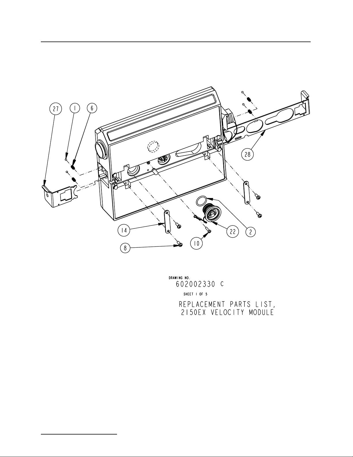
2150EX Area Velocity Flow Module
Appendix A Replacement Parts
A-2
Page 93

2150EX Area Velocity Flow Module
Appendix A Replacement Parts
A-3
Page 94

2150EX Area Velocity Flow Module
Appendix A Replacement Parts
A-4
Page 95
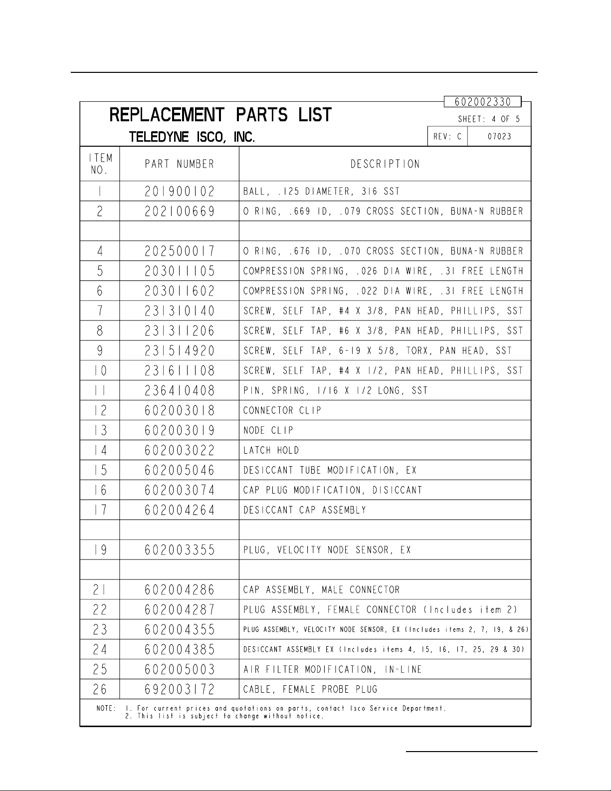
2150EX Area Velocity Flow Module
Appendix A Replacement Parts
A-5
Page 96

2150EX Area Velocity Flow Module
Appendix A Replacement Parts
A-6
Page 97

2150EX Area Velocity Flow Module
Appendix A Replacement Parts
This page left intentionally blank.
A-7
Page 98

2150EX Area Velocity Flow Module
Appendix A Replacement Parts
602002331 A
A-8
Page 99

2150EX Area Velocity Flow Module
Appendix A Replacement Parts
A-9
Page 100

2150EX Area Velocity Flow Module
Appendix A Replacement Parts
A-10
 Loading...