

Teledyne 2103, 2103Ci Installation And Operation Manual

2103/2103Ci
Part #69-2003-637 of Assembly #60-2004-637
Copyright © 2011. All rights reserved, Teledyne Isco
Revision A, April 6, 2012
Modem Module
Installation and Operation Guide


Foreword
This instruction manual is designed to help you gain a thorough understanding of the
operation of the equipment. Teledyne Isco recommends that you read this manual
completely before placing the equipment in service.
Although Teledyne Isco designs reliability into all equipment, there is always the possibility of a malfunction. This manual may help in diagnosing and repairing the malfunction.
If the problem persists, call or e-mail the Teledyne Isco Technical Service Department
for assistance. Simple difficulties can often be diagnosed over the phone.
If it is necessary to return the equipment to the factory for service, please follow the
shipping instructions provided by the Customer Service Department, including the
use of the Return Authorization Number specified. Be sure to include a note
describing the malfunction. This will aid in the prompt repair and return of the
equipment.
Teledyne Isco welcomes suggestions that would improve the information presented in
this manual or enhance the operation of the equipment itself.
Teledyne Isco is continually improving its products and reserves the right to
change product specifications, replacement parts, schematics, and instructions without notice.
Customer Service
Phone: (800) 228-4373 (USA, Canada, Mexico)
Fax: (402) 465-3022
Email: IscoCSR@teledyne.com
Technical Support
Phone: (800) 775-2965 (Analytical)
Email: IscoService@teledyne.com
Return equipment to: 4700 Superior Street, Lincoln, NE 68504-1398
Other Correspondence
Mail to: P.O. Box 82531, Lincoln, NE 68501-2531
Email: IscoInfo@teledyne.com
Web site: www.isco.com
Contact Information
(402) 464-0231 (Outside North America)
(866) 298-6174 (Samplers and Flow Meters)
Revised March 17, 2009


2103 Modem Module
Table of Contents
Section 1 Introduction
1.1 Introduction ........................................................1-1
1.2 Product Description .................................................. 1-1
1.3 Identifying Module Components .......................................1-2
1.4 Safety Symbols and Hazard Alerts ..................................... 1-6
1.5 Technical Service....................................................1-6
Section 2 Preparation and Installation
2.1 Unpacking Instructions .............................................. 2-1
2.1.1 2103Ci Label Information .......................................2-1
2.2 Installation ........................................................2-2
2.2.1 Latches - Locking and Unlocking .................................2-2
2.2.2 Communication Connectors .....................................2-3
2.2.3 Stacking Modules .............................................. 2-3
2.3 Telephone Line Connection (2103 only) .................................. 2-4
2.3.1 Modem Cable Connection ....................................... 2-5
2.3.2 Connection Without the Modem Cable .............................2-5
2.4 Antenna (2103Ci Only) ...............................................2-6
2.5 Connecting to Flowlink ............................................... 2-7
2.6 Modem Site Connection .............................................2-12
2.6.1 2103 Modem Connection ....................................... 2-12
2.6.2 2103Ci Modem Connection .....................................2-13
2.7 Setting Up Text Messaging (2103Ci) ...................................2-16
2.8 Power Conservation for Cellular Modems (2103Ci) .......................2-17
2.8.1 Equation ....................................................2-19
2.9 Pushed Data Capability .............................................2-20
Section 3 Modbus Protocol
3.1 Introduction ........................................................3-1
3.2 Operation ..........................................................3-1
3.2.1 Establishing Communication ....................................3-2
3.2.2 Module Addressing ............................................3-2
3.3 Configurations ......................................................3-3
3.4 Glossary of Terms ...................................................3-4
3.5 Common Acronyms ..................................................3-5
3.6 Register Specifications ............................................... 3-5
Section 4 Maintenance
4.1 Maintenance Overview ............................................... 4-1
4.1.1 Cleaning .....................................................4-1
4.2 Maintenance Kit ....................................................4-1
4.3 Desiccant ..........................................................4-2
4.3.1 Replacing the Desiccant ........................................4-2
4.3.2 Reactivating the Desiccant ......................................4-2
4.4 Hydrophobic Filter ..................................................4-3
iii

2103 Modem Module
Table of Contents
Appendix A Replacement Parts
Appendix B Accessories
Appendix C Material Safety Data Sheets
List of Figures
4.5 O-Rings ...........................................................4-3
4.6 How to Obtain Service ...............................................4-3
A.1 Replacement Parts ..................................................A-1
A.1.1 2103 Modem Module ...........................................A-2
A.1.2 2103
A.1.3 Antenna .....................................................A-8
B.1 How to Order.......................................................B-1
B.2 General Accessories .................................................B-1
C.1 Overview ..........................................................C-1
1-1 2103 Modem Components - Top View ...................................1-2
1-2 2103 Modem Components - Bottom View ................................ 1-3
1-3 2103 Communication Connector Pins ...................................1-5
1-4 2103 Modem Cable Connector .........................................1-5
2-1 2103Ci label ....................................................... 2-1
2-2 Connecting the Modem Cable .........................................2-5
2-3 2103 Modem Cable Connector .........................................2-6
2-4 Antenna connector (left) and antenna connected to 2103Ci (right) ............ 2-6
2-5 Flowlink connect screen (version 5.10.616) ..............................2-8
2-6 Site resolution screen ................................................2-9
2-7 Site Information screen .............................................2-10
2-8 Devices screen - connected to site .....................................2-11
2-9 Devices screen - 2103 module ........................................ 2-12
2-10 Modem screen - configuring the cellular modem ........................2-13
2-11 Devices screen - configuring the modem for Serial-Over-IP communication . . 2-14
2-12 Devices screen - configuring the modem for CSD communication ..........2-15
2-13 Setting up text messaging and alarm conditions ........................ 2-16
2-14 Wireless power control window ......................................2-18
2-15 Equation Builder for power control ...................................2-19
2-16 Condition Builder .................................................2-19
2-17 Data tab ........................................................2-20
3-1 Configuration example ...............................................3-3
Ci Cellular Module .........................................A-5
List of Tables
1-1 2103 Modem Module Components - Top View ............................ 1-2
1-2 2103 Modem Module Components - Bottom View .........................1-3
1-3 2103 Modem Module Technical Specifications ............................1-4
1-4 Specifications – 2191 Battery Module ...................................1-4
1-5 2103 Communication Connector Pins (2103 only) ......................... 1-5
3-1 Modbus ASCII Address 1 Register Definitions ............................ 3-6
3-2 Modbus ASCII Address 2+(N-1) Register Definitions ......................3-6
3-3 2100 Measurement Parameters by Model Number* .......................3-8
iv

2103 Modem Module
Section 1 Introduction
1.1 Introduction This instruction manual is designed to help you gain a thorough
understanding of the operation of the 2103 and 2103Ci Modem
Modules. Teledyne Isco recommends that you read this manual
completely before placing the equipment into service.
Information in this manual pertains to both the 2103 phone line
modem and the 2103Ci cellular modem. Where there are specific
differences between the modules, they are identified.
1.2 Product Description The 2103 Modem is a data communications unit designed to
transmit data from Isco’s 2100 Series flow modules, which
measure parameters of open channel flow streams. It works in
conjunction with Isco’s Flowlink software.
The 2103 Modem can be located anywhere within a stack of up to
three o ther 2100 Series networked modules, using the same
locking mechanism that connects the 2100 Series modules to
each other. The 2103 is compatible with Isco’s 2150 Area Velocity
flow module, 2110 Ultrasonic flow module, 2101 Field Wizard,
and 2102 wireless module. It is powered by Isco’s 2191 battery
module.
All enclosures are rated NEMA 4X, 6P(IP68). The permanently
sealed enclosures are designed to meet the environmental
demands of many sewer flow monitoring applications. All connections between modules, sensors, and communication cables lock
in place. The locking mechanisms strongly secure the components and ensure a watertight seal.
1-1
2103 Modem Module
Section 1 Introduction
1.3 Identifying Module
Components
5
4
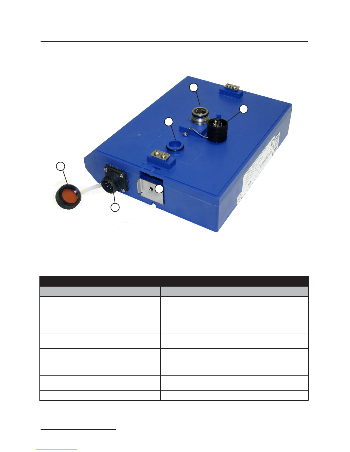
Figures 1-1 and 1-2 identify the key components of the 2103
Modem Module.
1
2
3
6
Figure 1-1 2103 Modem Components - Top View
Table 1-1 2103 Modem Module Components - TopView
Item No. Name Description
1 Communication Connector This port is used to connect the 2103 Modem to other modules
2 Connector Cap Insert into the communication connector when it is not in use to
3 Cap Holder Stores the connector cap when the communication connector is
4 Modem Cable Connector
(2103 only)
5 Modem Cable Connector Cap Insert into the modem cable connector when the connector is
6 Latch Release Push in to unlock the module from a stack.
in a stack.
protect the connector from moisture damage. When the connector is in use, store the connector cap in the cap holder.
in use.
Used to connect the modem cable to the 2103 Modem Module.
(On the 2103
ent appearance, and is used to connect the magnetic mount
antenna.)
not in use to protect the connector from damage.
Ci module, this side connector has a slightly differ-
1-2
2103 Modem Module
Section 1 Introduction
1
2
3
4
5
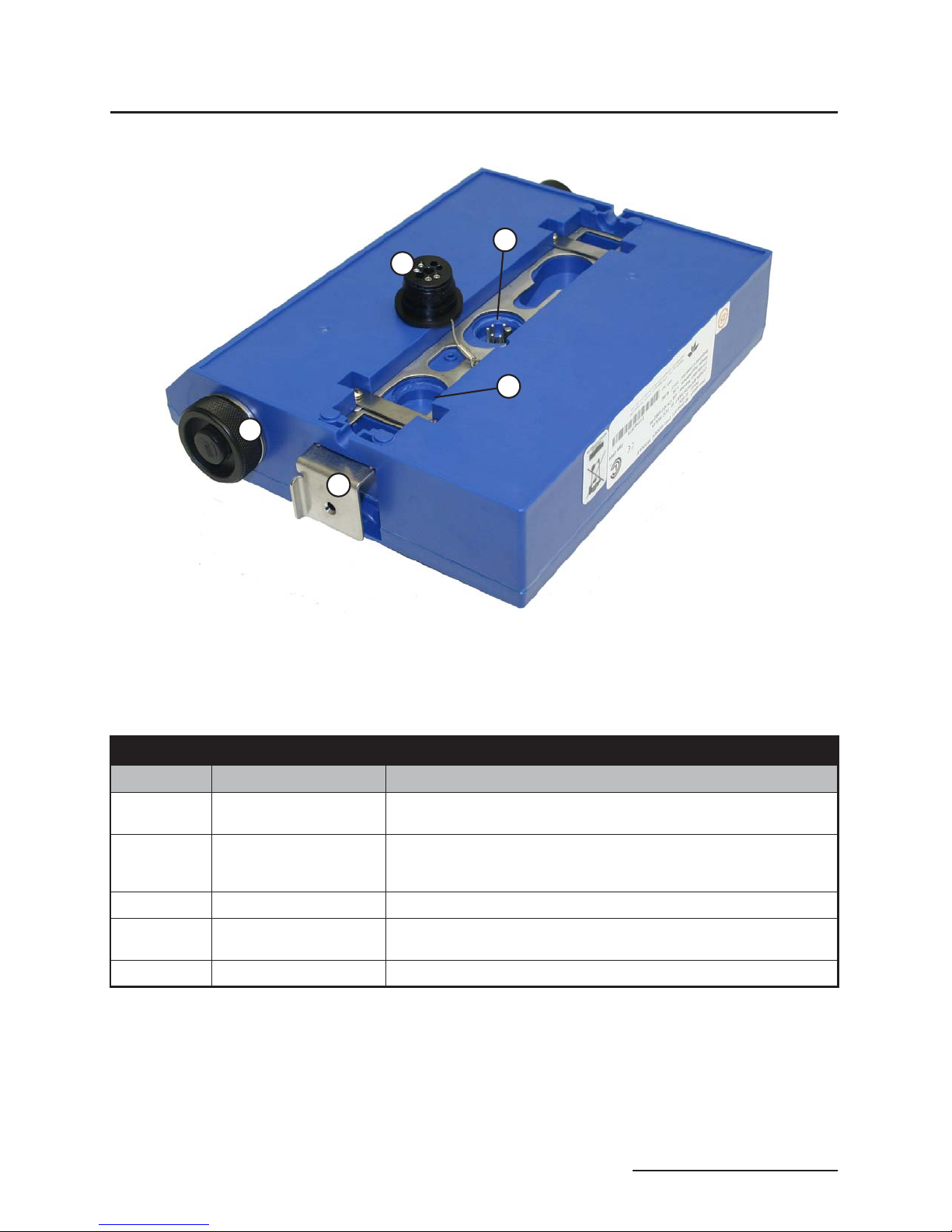
Figure 1-2 2103 Modem Components - Bottom View
Table 1-2 2103 Modem Module Components - Bottom View
Item No. Name Description
1 Communication Connector This connects the 2103 Modem to other 2100 Series modules in the
2 Connector Plug Insert into the communication connector when not in use to protect the
3 Plug Holder Stores the connector cap when the communication connector is in use.
4 Desiccant Cartridge and
Hydrophobic Filter
5 Latch Push in to lock the module in a stack.
stack and is used to transfer data.
connector from moisture damage. When the connector is in use, store
the connector plug in the holder.
Prevents moisture from entering the unit.
1-3

2103 Modem Module
Section 1 Introduction
Table 1-3 2103 Modem ModuleTechnical Specifications
Dimensions Length = 10.5 inches (26.7 cm)
Width = 7.5 inches (19 cm)
Height = 2.9 inches (7.4 cm)
Weight 2 lbs. (.9 Kg)
Material High-impact molded polystyrene
Enclosure NEMA 4X, 6P, IP68
Power 6.6 to 16.6 VDC, 141 mA typical at 12 VDC, 0.41 mA standby
Operating Temperature -4° to 140°F (-20° to 60°C)
Storage Temperature -40° to 140°F (-40° to 60°C)
Typical Battery Life 291 days*
Modulation Standards Supported
(2103 only)
Communication Speeds Supported 300, 1200, 2400, 4800, 7200, 9600, 12000, 14400, 16800, 19200,
Optional Cellular Communication Serial Over IP, or CSD (2103
Error Correction Standards Supported V.42 LAPM, MNP-2, MNP-4, MNP-10
Data Compression Standards Supported V.42 bis, MNP-5
Actual battery life will vary depending upon configuration. The figure given assumes interrogation with Flowlink once a week, with a site configuration
*
of a 2103, 2150, and 2191 (using Energizer 529 batteries) and a connection speed of 33600 baud. The 2150 was configured to record level, velocity,
flow rate every 15 minutes, total flow, and battery voltage every 24 hours.
Bell 103, Bell 212, V.21, V.22, V.22 bis, V.23, V.32, V.32 bis, V.34
21600, 24000, 26400, 28800, 31200, 33600 bps
CI)
Table 1-4 Specifications – 2191 Battery Module
Size (HWD) 6.0 9.6 7.6 in. 15.2 24.4 19.3 cm
Weight (without batteries) 3.2 lbs. 1.4 kg
Materials ABS plastic, stainless steel
Enclosure (self-certified) NEMA 4X, 6P IP68
Batteries 6V alkaline lantern or lead-acid lanter n, quantity 2
Capacity
Alkaline Lanter n Batteries 25 Ahrs
Lead-acid Lanter n
Batteries
1-4
5 Ahrs
2103 Modem Module
Section 1 Introduction
G
F
A
E
D
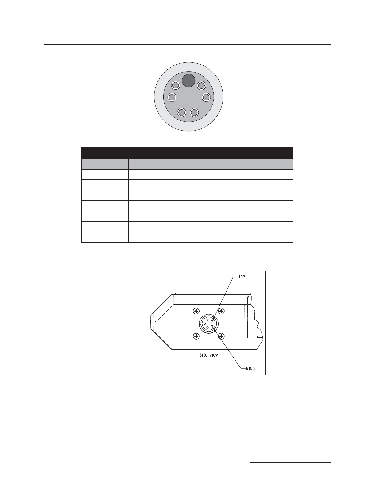
Table 1-5 2103 Communication Connector Pins (2103 only)
Pin Name Description
A LONA Neuron differential transceiver Data A
B LONB Neuron differential transceiver Data B
C VIN+ Positive power supply voltage input (+12 VDC nominal)
D VIN– Negative power supply voltage input (0 VDC nominal)
E RCVUP PC data receiver inverted input
F XMTUP PC data transmit inverted output
G Key Aligns connector pins
Figure 1-3 2103 Communication Connector Pins
B
C
Figure 1-4 2103 Modem Cable Connector
1-5

2103 Modem Module
Section 1 Introduction
1.4 Safety Symbols and
Hazard Alerts
essary to correct the condition. The manual presents this information in one of two ways:
This icon identifies a general hazard and is accompanied
with details about the hazard. The instruction manual
identifies the hazardous condition and any steps nec-
CAUTION
Cautions identify a potential hazard, which if not avoided, may
result in minor or moderate injury. This category can also warn
you of unsafe practices, or conditions that may cause property
damage.
WARNING
Warnings indicate potentially hazardous conditions. If you
do not avoid these risks, they could cause you death or
serious injury.
1.5 Technical Service Although Teledyne Isco designs reliability into all of its
equipment, there is always the possibility of a malfunction
occurring. You can use this manual to help in diagnosing and
repairing any malfunctions. If the malfunction persists, call or
write the Teledyne Isco Technical Service Department for assistance:
Teledyne Isco
Technical Service Department
P.O. Box 82531
Lincoln, NE 68501
866-298-6174 or 402-464-0231
FAX: 402-465-3001
e-mail: IscoService@teledyne.com
1-6
Simple difficulties can often be diagnosed over the phone. If it is
necessary to return the equipment to the factory for service,
please follow the shipping instructions provided by the Technical
Service Department, including the use of the Return Authorization Number specified. Be sure to include a note describing the
malfunction. This will aid in the prompt repair and return of the
equipment.
2103 Modem Module
Section 2 Preparation and Installation
2.1 Unpacking
Instructions
Teledyne Isco
Customer Service Dept.
P.O. Box 82531
Lincoln, NE 68501 USA
Phone: (800) 228-4373
Outside USA & Canada call:
(402) 464-0231
FAX: (402) 465-3022
E-mail: IscoInfo@teledyne.com
2.1.1 2103Ci Label
Information
When the system arrives, inspect the contents for any damage. If
there is damage, contact the delivery company and Teledyne Isco
(or its agent) immediately.
WARNING
If there is any evidence that any items may have been
damaged in shipping, do not attempt to install the unit.
Please contact Teledyne Isco (or its agent) for advice.
When you unpack the system, check the items against the
packing list. If any parts are missing, contact the delivery
company and Teledyne Isco’s Customer Service Department.
When you report missing part(s), please indicate them by part
number. In addition to the main packing list, there may be other
packing lists for various sub-components.
It is recommended that you retain the shipping cartons as they
can be used to ship the unit in the event that it is necessary to
transport the system.
Please complete the registration card and return it to Teledyne
Isco.
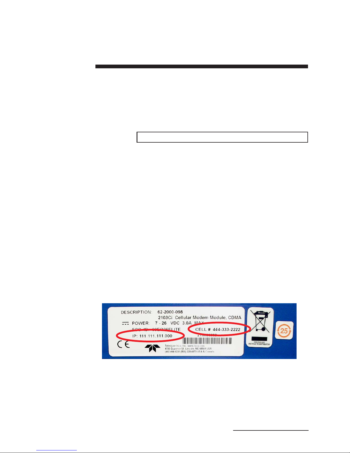
If you have a 2103Ci, you should record the IP address and phone
number printed on the label, found on the back of the unit
(Figure 2-1). You will need this information when you configure
the unit.
Figure 2-1 2103Ci label
2-1

2103 Modem Module
Section 2 Preparation and Installation
2.2 Installation The 2100 Series components are often i nstalled in confined
spaces. Some examples of confined spaces include manholes,
pipelines, digesters, and storage tanks. These spaces may become
hazardous environments that can prove fatal for those unprepared. These spaces are governed by OSHA 1910.146 and require
a permit before entering.
WARNING
Avoid hazardous practices! If you use these instruments in
any way not specified in this manual, the protection
provided by the instruments may be impaired; this will
increase your risk of injury.
WARNING
The installation and use of this product may subject you
to hazardous working conditions that can cause you
serious or fatal injuries. Take any necessary precautions
before entering a worksite. Install and operate this product
in accordance with all applicable safety and health
regulations, and local ordinances.
2.2.1 Latches - Locking and
Unlocking
Follow the instructions below to install your 2103 Modem. Most
of these instructions are similar for the 2103Ci. Where there are
differences, they are specifically identified.
Latches must be operated to stack and unstack t he modules in a
Series 2100 stack. The mechanisms are the same for the 2103
Modem and other 2100 Series modules. Detailed instructions
with photos can be found in your 2150 instruction manual.
Take a moment to familiarize yourself with operating the latches.
You must unlock the latch to place the module on top of another
module in a stack. The latch is unlocked by pushing in the latch
release on the right side of the module. To lock the latch, push in
the latch on the left side of the module.
CAUTION
The latch can be damaged by applying too much force. Never
press on both sides at the same time. Do not force the latch if it
is obstructed. While some degree of pressure must be applied
to slide the latch, the ends of the latches should never bend
more than1/8”.
Note
Latches will “click” when they are fully locked and unlocked.
2-2

2103 Modem Module
Section 2 Preparation and Installation
2.2.2 Communication
Connectors
Connecting the 2103 Modem module involves uncapping and
capping communication connectors. When a communication connector is not in use, the connector should always be capped. The
cap will seal the connector to prevent corrosion, and will improve
communications.
When a communication connector is in use, store the cap on the
holder next to the connector. The communication connector will
be sealed by its mating connector.
Detailed instructions and photos can be found in your 2150 or
2110 instruction manual.
CAUTION
Caps PUSH ON and PULL OFF. Do not rotate the caps to
remove them from the connectors.
Note
For modules to correctly stack and lock together, protective
caps between the modules must be stored on the holders.
2.2.3 Stacking Modules The 2103 Modem Module can be located anywhere within a stack
of up to three 2100 Series networked modules. It will draw its
power from the battery module located in the stack.
To connect the 2103 with a 2100 Series module, refer to the following instructions.
1. On the top of the 2100 Series module, remove the cap and
stow it on the holder. This exposes the communication connector on the module.
2. Inspect the module’s communication connector. It should
be clean and dry. Damaged O-rings must be replaced.
3. Unlock the 2103’s latch by pressing in on the latch release
(right side).
4. Underneath the 2103, remove the cap from the lower communication connector and stow it in the holder.
5. Lock the latch. Locking the latch correctly seats and aligns
the lower cap in its holder.
6. Position the 2103 over the 2100 Series module. Align the
connectors and lower the 2103 onto the other module.
7. Unlock the 2103’s latch by pressing in on the latch release
(right side).
8. Firmly press the modules together and lock the 2103’s
latch (left side).
The communications indicator will blink during the start-up
routine to indicate the 2103 is operating.
2-3
2103 Modem Module
Section 2 Preparation and Installation
2.3 Telephone Line
Connection (2103
only)
The FCC (Federal Communications Commission) governs communications over telephone lines. Your local telephone company
will provide you with the line between the 2103 Modem and your
computer. Contact them for connection information.
The 2103 Modem Module is in compliance with FCC part 68
rules. However:
Note
In tests conducted by the Communication Certification Laboratory, the 2103 Modem did not pass conducted RF testing on
telephone line at 5 MHz, 3V RMS. For details, see international
standard EN 61000-4-6. In the event of this failure, the modem
may be subject to disconnection.
Accordingly, the FCC requires the following information
be published:
Note
The 2103 Modem is designed to be used on standard device
telephone lines. It connects to the telephone by means of a
standard jack called the USOC RJ-11C. Connection to telephone-company-provided coin service (central office implemented systems) is prohibited, and connection to party lines
service is subject to state tariffs.
Changes in Attestation Procedure for Plugs and Jacks
Teledyne Isco attests that the network interface plugs or jacks
used on this equipment comply with and will continue to comply with the mechanical requirements specified in Part 58,
sub-part F, specifically the dimensions, tolerances and metallic
plating requirements. The compliance of these connectors will
be assured by purchase specifications and incoming inspection. Documentation of such specifications and/or inspections
will be provided to the FCC within 30 days of their request for
the same.
Telephone Company Procedures
The goal of the telephone company is to provide you with the
best ser vice it can. In order to do this, it may occasionally be
necessary for them to make changes in their equipment, operations or procedures. If these changes might affect your service or the operation of your equipment, the telephone
company will give you notice, in writing, to allow you to make
any changes necessary to maintain uninterrupted service.
2-4
In certain circumstances, it may be necessar y for the telephone company to request information from you concerning
the equipment which you have connected to your telephone
line. Upon request of the telephone company, provide the FCC
registration number and the ringer equivalence number (REN);
both of these items are listed on the equipment label. The sum
of all the RENs on your telephone lines should be less than
five in order to assure proper service from the telephone company.Insomecases,asumoffivemaynotbeusableona
given line. Consult your telephone provider.
2103 Modem Module
Section 2 Preparation and Installation
If Problems Arise: If any of your telephone equipment is not
operating properly, you should immediately remove it from your
telephone line, as it may cause harm to the telephone network.
If the telephone company notes a problem, they may temporarily discontinue service. When practical, they will notify you in
advance of this disconnection. If advance notice is not feasible,
you will be notified as soon as possible. When you are notified,
you will be given the opportunity to correct the problem and will
be informed of your right to file a complaint with the FCC. Contact your local telephone service provider if you have any questions about your phone line.
In the event repairs are needed on the 2103 Modem, they
should be performed by Teledyne Isco or its authorized representative. For information, contact the Teledyne Isco Customer
Service Department at (866) 298-6174 or (402) 464-0231.
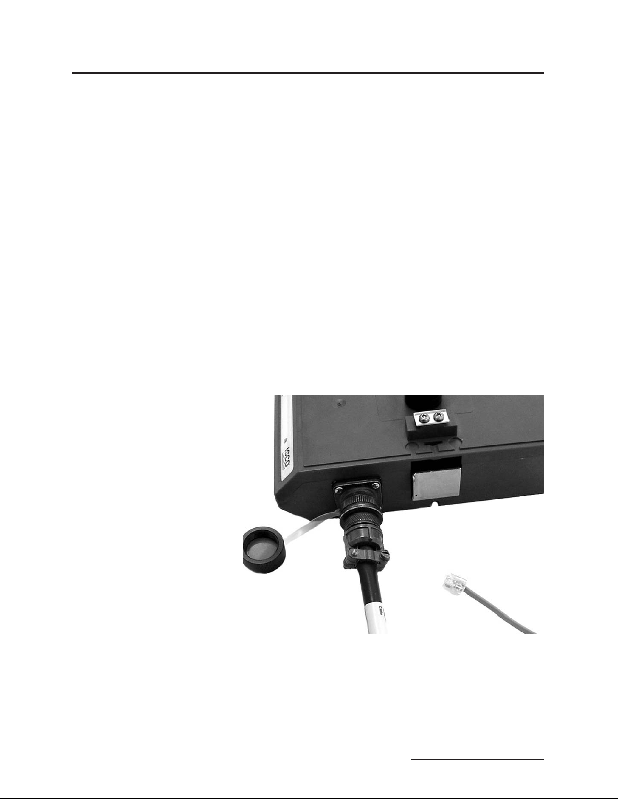
2.3.1 Modem Cable
Connection
After you have installed the 2103 on the stack, you need to attach
the modem cable so the module can be connected to a phone line.
Remove the connector cap from the 5-pin circular modem cable
connector on the right hand side of the 2103. Attach the modem
cable to the connector (Figure 2-1), and then connect the other
end of the modem cable to a standard telephone jack (USOC
RJ-11C).
Figure 2-2 Connecting the Modem Cable
2.3.2 Connection Without
the Modem Cable
If desired, the 2103 can be connected to a standard telephone line
by attaching the telephone line cable to a connector that mates
with the 2103’s 5-pin circular modem cable connector (Figure
2-2). Be sure that you have a water tight seal on your wire connections.
2-5
2103 Modem Module
Section 2 Preparation and Installation
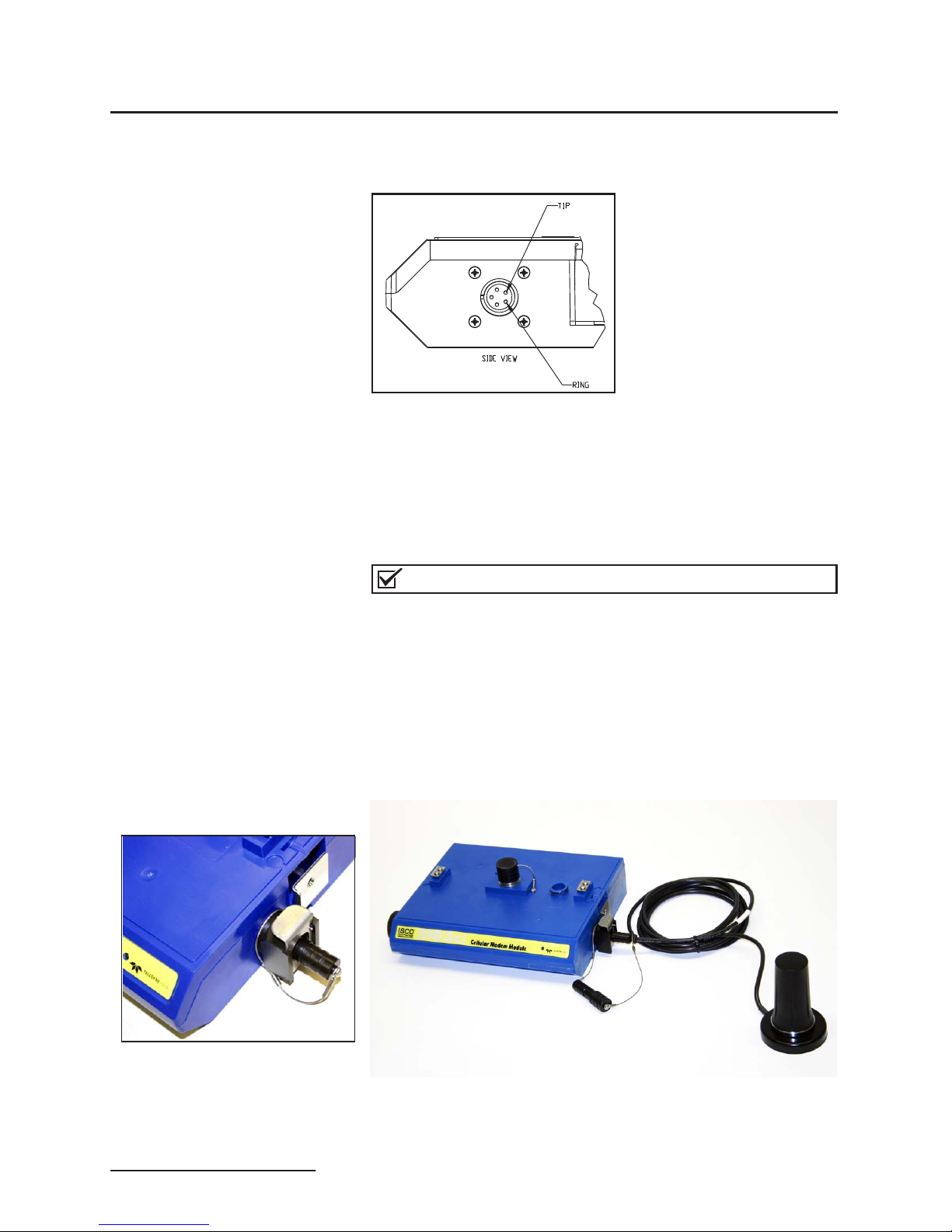
For your reference, the modem cable uses a 5-pin amphenol
socket, MS3106A-5S.
Figure 2-3 2103 Modem Cable Connector
2.4 Antenna (2103Ci Only) The 2103Ci uses a magnetic mount antenna and Serial Over
Internet Protocol (SOIP) communication to connect with other
units. (The module is also capable of CSD communication, but
this service is being phased out. See Section 2.6.2 for complete
information.) Phone service with a static IP address, rather than
a land line, provides efficient communication.
Note
The 2103Ci only works in a CDMA cellular service area with
1xRTT. See your local CDMA service provider for availability.
As you face the unit, the 2103Ci antenna connector socket is
located on the right hand side of the module (Figure 2-4). Remove
the connector cap from the socket and attach it to the cap on the
end of the antenna cable. To connect the antenna, press down on
the silver metal latch on the side of the module and push the
antenna’s connector into the socket.
Figure 2-4 Antenna connector (left) and antenna connected to 2103Ci (right)
2-6
2103 Modem Module
Section 2 Preparation and Installation
CAUTION
Only use this antenna with 2100 Series Ci cellular modem
modules. Do not use this antenna with non-Ci equipment.
Note
For the transmitter to comply with FCC Maximum Permissible
Exposure (MPE) regulations, the antenna must be located a
minimum of 30 centimeters (12 inches) from the human body.
Note
When any communication connector is not in use, it should
always be capped. The cap will seal the connector to prevent
corrosion, prevent moisture from entering the unit, and improve
communications.
2.5 Connecting to
Flowlink
Once the system is installed, you will configure it in a new or
existing site using Isco’s Flowlink software.
Note
The 2103 and 2103Ci Modems require Flowlink 5.10.412a or
later. Earlier versions do not support the modems.
The first time you connect to the site, you must connect your
computer directly to the stack using Isco’s RS232 connect cable
(part #60-2004-046) or USB port connect cable
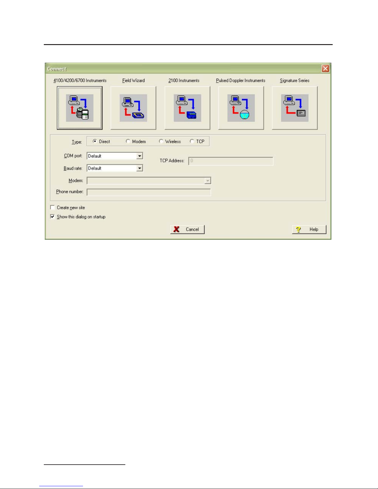
(part #60-2004-507). Open Flowlink and go to the Connect screen
(Figure 2-5) by either selecting it from the pull down menu or
clicking on the Quick Connect icon.
Make sure the connection Type is Direct, and click on the 2100
Instrument icon to connect. Upon initial connection, Flowlink
creates a site file and adds it to the database. If the system
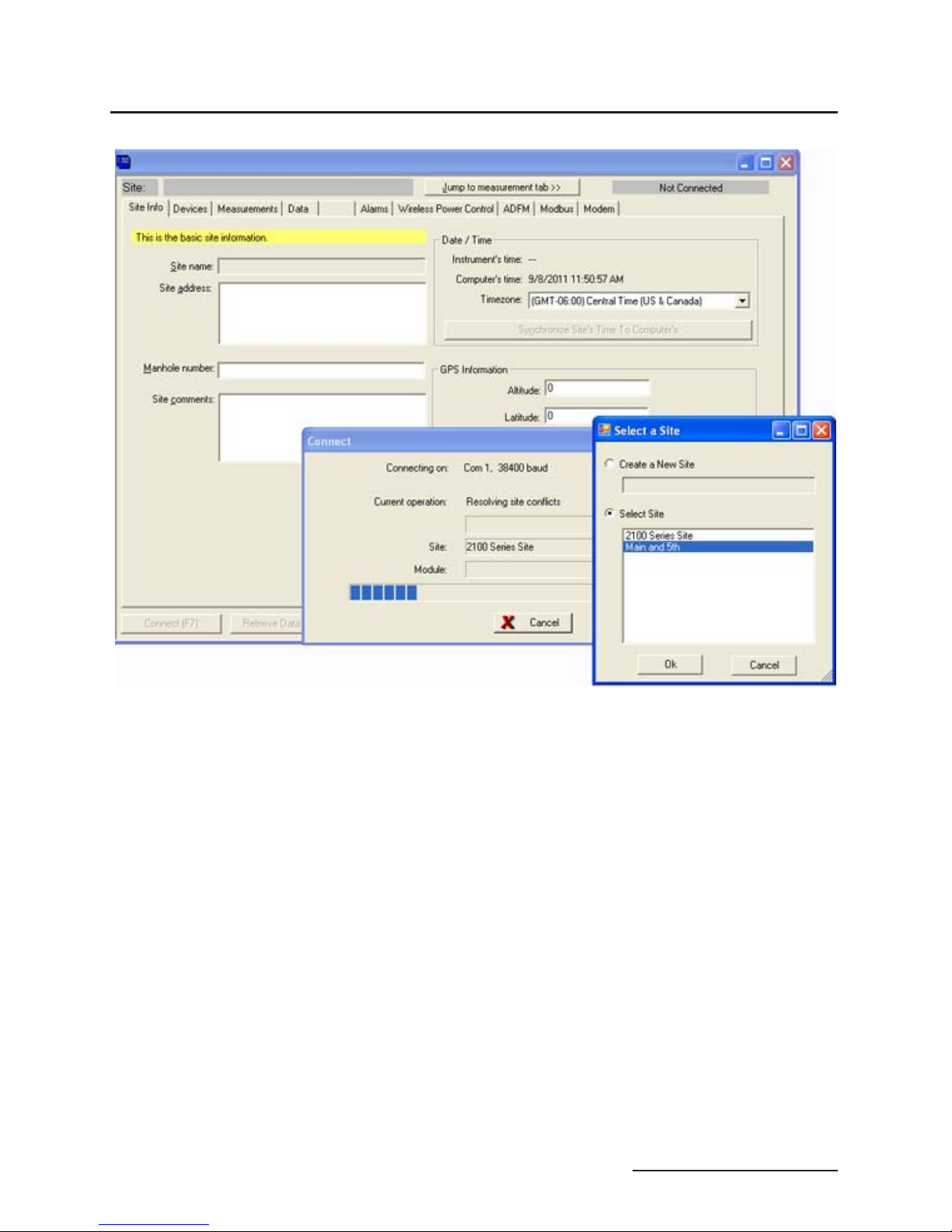
detects the addition of a new module to an existing site, it will
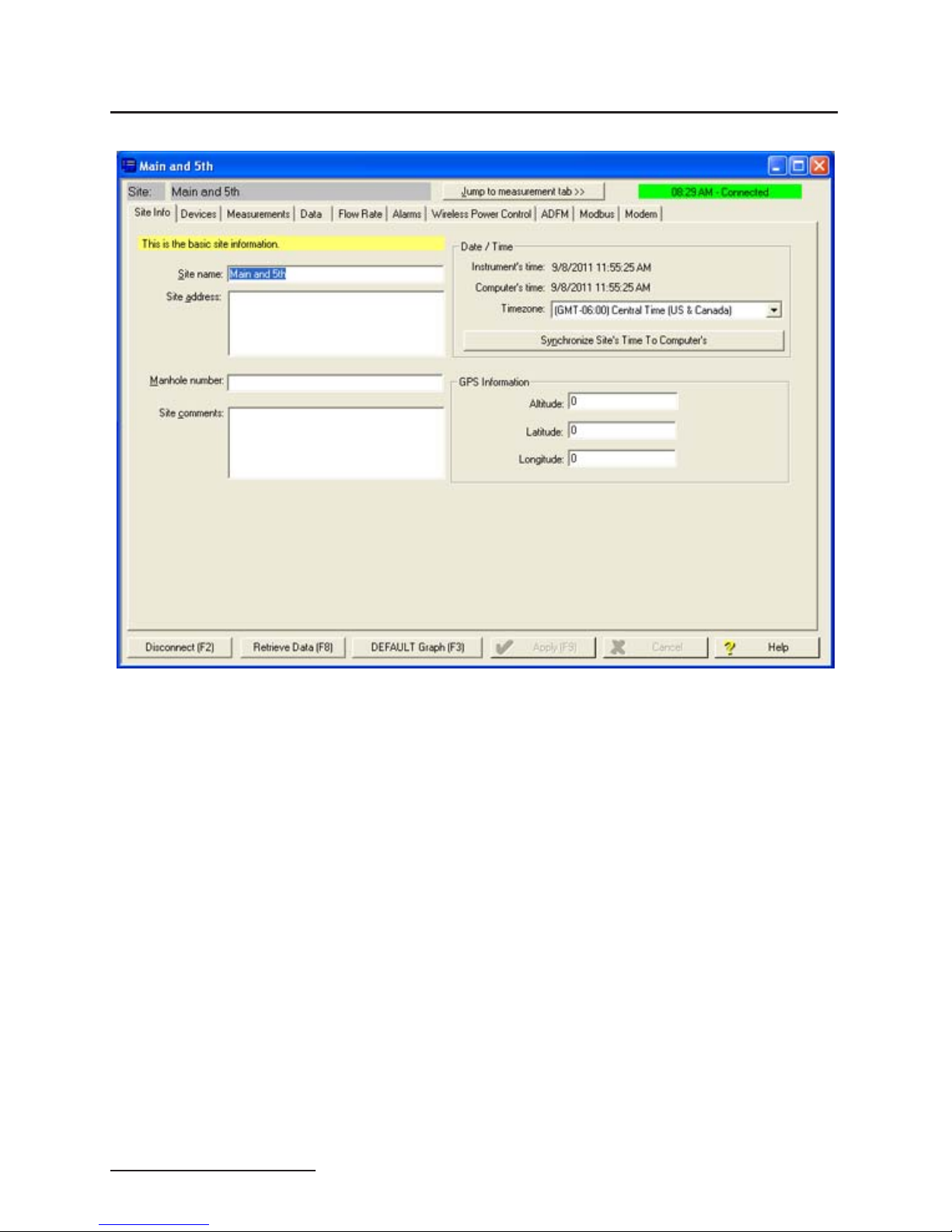
display the Site Resolution screen (Figure 2-6). Otherwise, it will
display the Site Info screen (Figure 2-7).
2-7
2103 Modem Module
Section 2 Preparation and Installation
Figure 2-5 Flowlink connect screen (version 5.10.616)
2-8
2103 Modem Module
Section 2 Preparation and Installation
Figure 2-6 Site resolution screen
To add the new module to an existing site, select the appropriate
site and click OK. To create a new site, select Create a New Site.
Click in the name field, enter the name for the site, and click OK.
Upon connection, the Site Info tab will appear.
2-9
2103 Modem Module
Section 2 Preparation and Installation
Figure 2-7 Site Information screen
2-10
2103 Modem Module
Section 2 Preparation and Installation
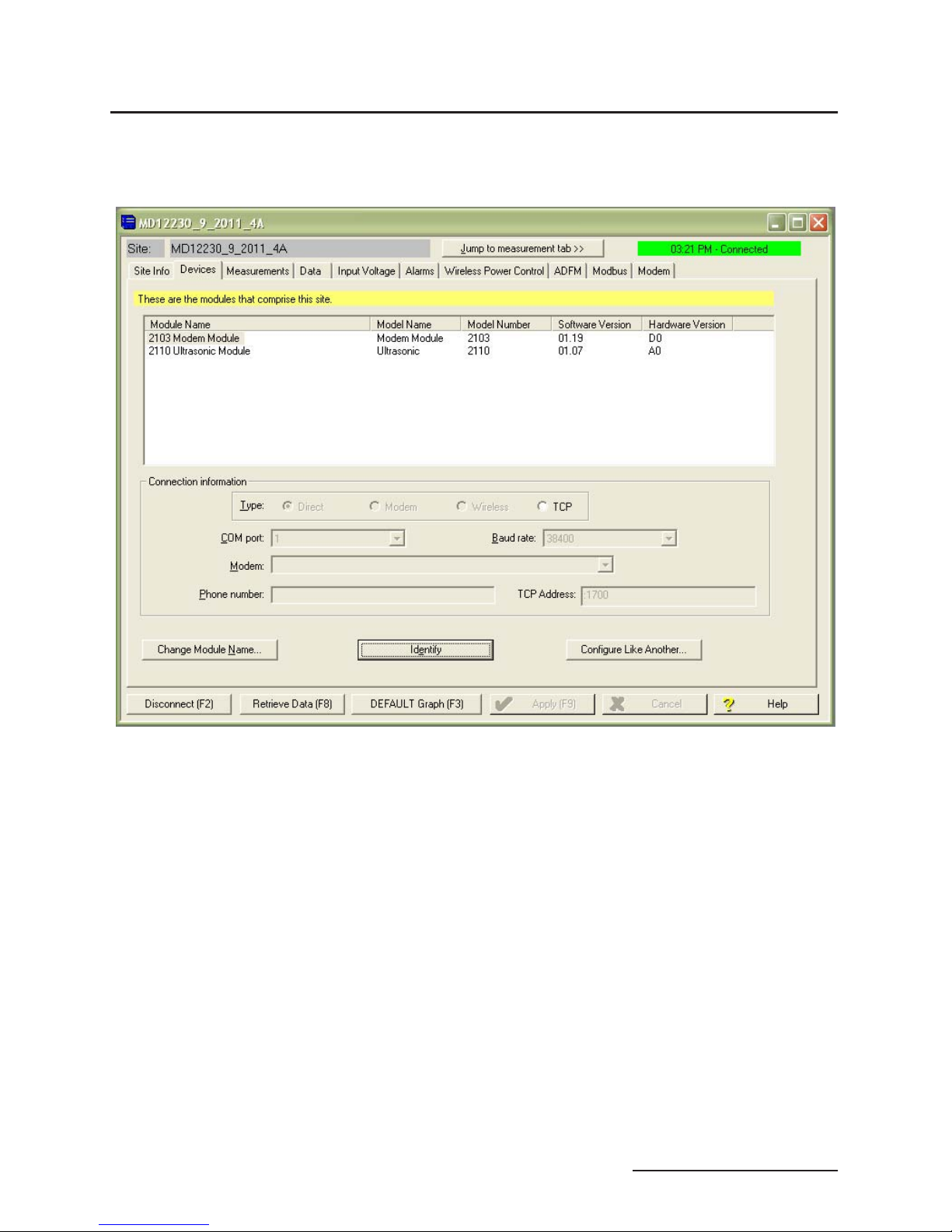
When the module has been added to the system, you will see the
Devices screen (Figure 2-8).
Figure 2-8 Devices screen - connected to site
This window displays all of the modules connected to the site.
2-11
 Loading...