

Telect GMT Series, 0HPGMT Installation Manual
High-Power GMT Series Fuse Panels
Models 0HPGMT Installation Guide

High-Power GMT Series Fuse Panels
Models 0HPGMT Installation Guide
7
1.509.926.6000 :: telect.com
2
Installation Guide, Part Number 130316-7
Copyright 2016, Telect, Inc., All Rights Re s erved
Telect and Connecting the Future are registered trademarks of
Telect, Inc.
22425 East Appleway Avenue, # 11
Liberty Lake, WA 99019
Telect assumes no liability from the application or use of these products. Neither does Telect convey any
license under its patent rights nor the patent rights of others. This document and the products described
herein are subject to change without notice.
Connecting the future for over 30 years
Telect challenges the status quo and looks beyond what is possible in network connectivity and
power management.
Founded in 1982, Telect is driven by the principles of innovation and customer service. Headquartered in
Liberty Lake, WA, the privately held company supports a global network of customers with a comprehensive
product portfolio and a values-driven corporate culture.
Our products and solutions are found across communications service-provider networks, data centers and
utility networks around the globe.
At Telect, we pride ourselves on our ability to respond to customer challenges, building a reputation among
communications service providers for delivering solutions uniquely tailored to their needs.
We simplify networks.™
• Exceptional lead-times
• Custom configured solutions
• Rapid collaborative developing and prototyping
• UL and NEBS expertise
Technical Support
Phone: 509.926.6000
Email: getinfo@Telect.com
© Telect, Inc. All rights reserved. 5.1.17 130316-

High-Power GMT Series Fuse Panels
Models 0HPGMT Installation Guide
7
1.509.926.6000 :: telect.com
3
Table of Contents
1.1 Overview ............................................................................................................................................... 4
1.1.1 Specifications ................................................................................................................................ 2
1.1.2 Standard & Special Features ......................................................................................................... 5
1.1.2.1 Bay & Failure Alarm Options ................................................................................................. 6
1.1.2.2 Power-Line Noise Filter ......................................................................................................... 7
1.2 Inspection .............................................................................................................................................. 8
1.3 Installation Considerations ..................................................................................................................... 8
1.4 Installation Procedures .......................................................................................................................... 9
1.4.1 Installing the Panel ........................................................................................................................ 9
1.4.2 Replacing the Alarm Board .......................................................................................................... 13
1.5 Parts & Accessories ............................................................................................................................. 14
1.6 Service ................................................................................................................................................ 15
1.7 Block Diagram ..................................................................................................................................... 16
1.8 1RU Dimensions .................................................................................................................................. 17
1.9 2RU Dimensions .................................................................................................................................. 18
List of Figures
Figure 1 - Models 0HPGMT ......................................................................................................................... 1
Figure 2 - Model 0HPGMT05R (Front View) ................................................................................................ 2
Figure 3 - Alarm Panel ................................................................................................................................. 6
Figure 4 - Model 0HPGMT05BR (Rear View) .............................................................................................. 6
Figure 5 - Alarms ......................................................................................................................................... 7
Figure 6 - Mounting Dimensions .................................................................................................................. 9
Figure 7 - Ground Lug Connection............................................................................................................. 10
Figure 8 - Compression Lug Inputs ............................................................................................................ 10
Figure 9 - Alarm Board ............................................................................................................................... 13
Figure 10 - Power, Battery Return and Fuse Circuit ................................................................................... 16
© Telect, Inc. All rights reserved. 5.1.17 130316-
High-Power GMT Series Fuse Panels
Models 0HPGMT Installation Guide
7
1.509.926.6000 :: telect.com
4
1.1 Overview
Telect’s High-Power GMT Series Fuse Panels provide
protected secondary -48 VDC to telecommunications
equipment at the bay level (-48 VDC, nominal). Fuse
panels are available with GMT fuses in single-circuit
(10, 20, and 30) or dual-circuit (10/10, 15/15, and
20/20) configurations.
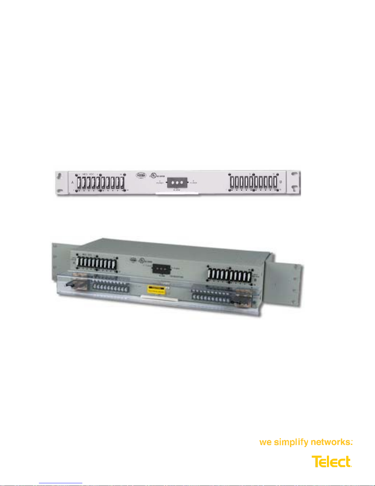
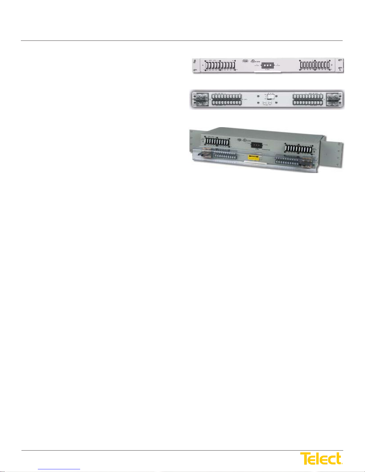
Shown on the right are the front and rear images of a
Dual-Circuit High-Power 10/10 GMT Fuse Panel and a
front corner view of a 10/10 GMT TFA Fuse Panel.
Standard features include:
• Single- or dual-circuit, 100A input bus(es), -48 VDC
Front View
Rear View
0HPGMT05R (1RU Panel)
0HPGMT12R (2RU Panel)
Figure 1 - Models 0HPGMT
• Discrete GMT fuse positions: 15A capacity without fuse management for heat dissipation
• Alarm circuit board replaceable with panel in service (hot-swap)
• Minimal rack space: one 1.75" EIA or 2" WECO rack unit (1RU) for rear access connections; 2RU for total
front access of dual-circuit 10/10 configuration
• 19" or 23" rack mounting, with mounting brackets provided (Dual-Circuit 20/20 Panel requires a 23" rack)
• Transparent terminal cover to meet electrical and equipment safety standards
• Dummy GMT fuses provided for all fuse holders
• Holes provided in chassis for inserting colored fuse designation pins
• NEBS Level 3 (Zone 4) and CE certified
• Fire rating: UL 94V-0 and/or VW-1 (for writing)
Special features include:
• Noise Filter Circu itry (0HPGMT05NR)
© Telect, Inc. All rights reserved. 5.1.17 130316-
High-Power GMT Series Fuse Panels
Models 0HPGMT Installation Guide
7
1.509.926.6000 :: telect.com
5
NEG 48 VDC
OHPGMT05R
Rev: A
SN:
WK-YR: 11 -1999
INPUT
INPUT
ALARM
15A MAX/FUSE
10
10
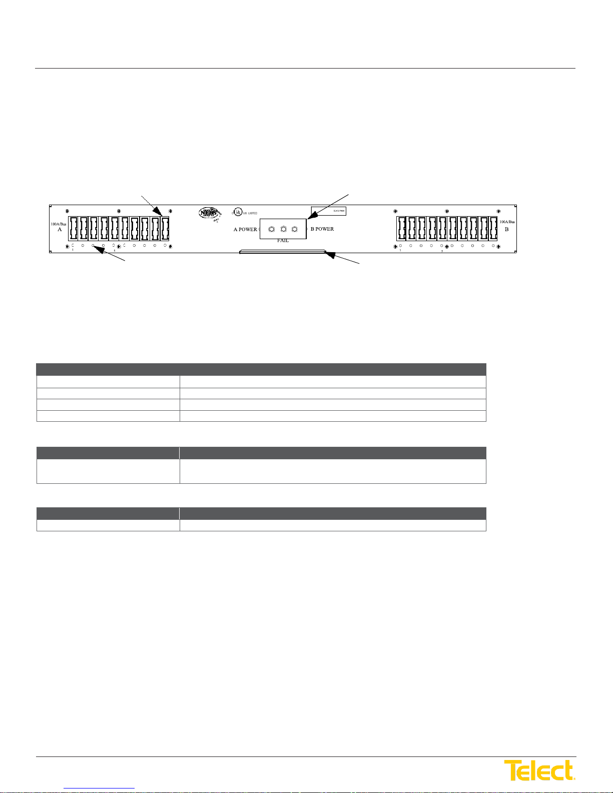
Holes for Designation Pins
Pullout Circuit Designation Card
Environment:
Specifications:
Temperature range
-25°C to 55°C (-13°F to 131°F)
Humidity
5% to 85% and non-condensing
Altitude range
-197 ft to 13,100 ft (-60 m to 4000 m)
Acoustic noise
0 dBA above ambient
Fit and Finish:
Specifications:
Material
(Custom color/finish available)
Cold-rolled steel, powder-coat telephone grey, baked polyurethane
Clear polycarbonate protective terminal cover
Weights (Approximate)
Specifications:
Weight
8 to 12 lb (~3.5 to 5.5 kg), depending on model
All models are recognized by UL for the USA and Canada with the exception of Models
0HPGMT02R, 0HPGMT03R, 0HPGMT05R, 0HPGMT07R, 0HPGMT08R and
0HPGMT12R, which are LISTED by UL for the USA and Canada.
Telect’s High-Power GMT Series Fuse Panels use discrete, not modular, GMT fuse
holders to limit heat buildup when using 15A GMT fuses.
Discrete GMT Fuse Holders
Replaceable Alarm Card
H
I
0206381
Figure 2 - Model 0HPGMT05R (Front View)
1.1.1 Specifications
© Telect, Inc. All rights reserved. 5.1.17 130316-

High-Power GMT Series Fuse Panels
Models 0HPGMT Installation Guide
7
1.509.926.6000 :: telect.com
6
Mechanical Interface:
Specifications:
Input terminals – Compression
Stud:
Torque:
¼-20 with nut. [Use 7/16" (12 mm) socket]
50 in.-lb (~5.5 N·m), max.
Output terminals –
Screw:
Torque:
#6 Phillips* panhead
6.5 in.-lb (~0.75 N·m), max.
Alarm terminals – Wire wrap
.045 in. square wirewrap pins on .156 in. centers
Use 18 to 22 AWG copper
Ground terminals
Screws:
2 #10 Phillips* panheads
* Screws with cross-recessed heads
Dimensions:
Specifications:
Dimensions (nominal)†,
0HPGMT12R & 0HPGMT02R
Width:
Depth:
17" (432 mm)
12" (305 mm)
Dimensions (nominal)†,
0HPGMT02R
Width:
Depth:
21" (533 mm)
12" (305 mm)
Dimensions (nominal)†,
0HPGMT12R
Width:
Depth:
17" (432 mm)
7.5" (190 mm)
† See Pages 17 and 18 for exact dimensions
Electrical Interface:
Specifications:
Operating voltages
-48 VDC, both sides
Current capacity:
All Except
0HPGMT05NR
100A per bus (200A total for dual-circuit panels), max.
75A per bus (150A total for both buses)
Fuse capacity:
Single circuit:
Dual circuit:
10, 20, or 30
20, 30, or 40 (total, both circuits)
Maximum input interruption device rating
125A for a 100A bus
90A for 75A bus
Maximum output interruption device rating
15A GMT fuse
Interrupt rating
450A
Short circuit withstand current
450A
Alarm contact relay
2A
Alarm board power rating @ 48 VDC
1W
Panel heat dissipation per 100A bus
1.0W (3.4 BTU/hr) @ 0%
21.3W (72.6 BTU/hr) @ 100%
Percentage of full load heat dissipation at
nominal voltage
Less than 1% of total load wattage
Wire binding/compression
without brackets for all but
without brackets for
Lugs:
Cable:
Wire:
Lug:
Spacing:
Lugs:
Cable:
Torque:
Height:
Height:
Dual-hole compression lug
(5/8" center to center) 0.516 in. (13.4 mm) max. lug width
Up to 1/0 AWG copper, depending on input interruption device
14 to 22 AWG, copper wire
10 to 22 AWG, copper wire
3/8" (9.5 mm) centerline with barrier distance of .260 in. (6.6 mm)
Single- or dual-hole compression lug (5/8" center to center)
Dual-hole lug is recommended
Up to #6 AWG copper for single-hole lug (Conductor size depends
on input interruption device)
21 in.-lb (~2.5 N·m), max.
1.75" (44.4 mm)
1.75" (44.4 mm)
without brackets for
@% load
© Telect, Inc. All rights reserved. 5.1.17 130316-
Height:
0HPGMT05NR
3.5" (89 mm)
1.2W (4.1 BTU/hr) @ 25%
4.8W (16.5 BTU/hr) @ 50%
11.4W (38.7 BTU/hr) @ 75%
 Loading...