

Page 1
Low-Current 20/20 GMT Series Fuse Panels
Models 06004-01 & 06004-11
Installation Guide
T elect’s 1RU T raditional Low-Current GMT Series Fuse Panels
provide protected secondary -24 Vdc to -48 Vdc power distribution to telecommunications equipment at the bay level. Fuse
panels are available for GMT outputs up to 10A per position in
dual-circuit panel configurations having 20 GMT fuse positions
per circuit.
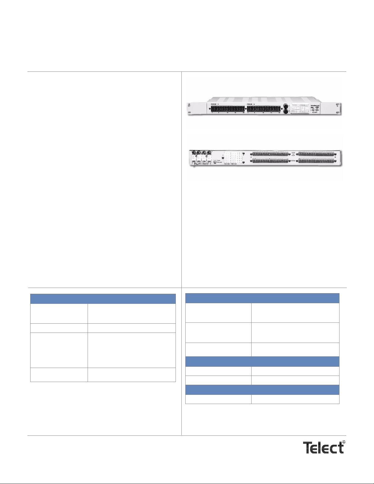
• Model 06004-01 is the standard panel containing separate Side A and Side B GMT fuse failure alarms and corresponding LEDs. Model 06004-01 standard features
include —
◊ Dual-circuit, 20A input bus for Side A and 20A for
Side B
◊ Minimal rack space: one, 1.75-in. EIA or 2-in. WECO
rack unit (1RU) for rear access connections
◊ 20 GMT outputs per side with each side protected by
a Type ABC 20A ceramic input fuse
◊ Dummy GMT fuses provided for all fuse holders.
Front
Rear
• Model 06004-11 adds separate power failure auxiliary
alarms for Sides A and B1 along with a load-sharing failsafe circuit. If power fails on one bus the other picks up the
loads on the failed bus.
◊ Two sets of Form C relay contacts per side for reli-
able fail alarm connections
◊ Side A and B alarms can be wired for separate or
common alarming
1
◊ 19-in. or 23- in. rack mounting, with mounting brack-
ets provided
PhysicalSpecifications
Dimensions (nominal
without bracket)*
Weight 8.5 lb (~3.8 kg)
Ground terminals Screws:#10-32 Phillips** panhead
Material†† Cold-rolled steel, powder-coat telcom
* See Page 10 for complete dimensioning.
** Screws with cross-recessed heads
†† Custom color/finish available.
Width:17 in. (432 mm)
Height:1.75 in. (44.4 mm)
Depth:9.25 in. (235.0 mm)
Torque:20 in.-lb (~2.26 N•m), max.
Wire:Same size as input terminals
Ring LugBurndy T1010, 12 AWG, no insulation; AMP 35771, 12-10 AWG, no
insulation
grey
Both models are UL recognized under UL File E199668.
1. All basic and auxiliary alarms can be wired for separate
or common alarming.
MechanicalSpecifications
Input terminals Type:Screw-tight, wire-clamping
Output terminals Type:Screw-tight, wire-clamping
Alarm terminals—
Wire Wrap
Environmental Specif ications
Temperature range, ambient -17°C to 49°C (0°F to 120°F)
Humidity 0% to 90% and noncondensing
Reliability
MTBF 200,000 hr
Wire:14 to 6 AWG, copper wire
Torque:16 in.-lb (1.80 N•m), max.
Wire:22 to 14, copper wire
Torque:4.5 in.-lb (0.51 N•m), max.
.045 in. square wire-wrap pins on .200
in. centers. Use 18 to 22 AWG copper
Telect, Inc. • USA +1.509.926.6000 • Mexico +52.33.3836.3700
Poland +48.713.239.100 • UK +44.1489.889500 • www.telect.com
Copyright © 2006 Telect, Inc., All Rights Reserved • 130358-2 A0
Page 1
Page 2
Electrical Specifications
Operating voltages, nominal -24 Vdc to -48 Vdc
Current capacity06004-01
06004-11
Fuse capacity 20 (ea side)
Maximum PDU input interruption device rating 25A per bus
Maximum output interruption device rating 10A GMT fuse
Maximum continuous output load rating 7A for a 10A fuse
Alarm contact relay 2A @ 30 Vdc
Panel heat dissipation per 20A bus 3.9W (13.3 Btu/hr) @ 0% load
Percentage of full load heat dissipation at nominal voltage less than 1% of total load wattage
20A per bus (40A total for both buses), max. with 20A ceramic input fuse (Type ABC)
15A per bus (30A total for both buses), max, with 20A ceramic input fuse (Type ABC)
20A Input Fuses for Circuits A & B
Designation Card Holder
"FAIL SAFE" Applies
only to Model 06004-11
20
POWER B
1
5
Circuit B Output
GMT Fuse Holders
A
10
15
20
B
FAIL SAFE
A
ALARM
B
Fuse Alarm LEDs for Circuits A & B
POWER A
1
5
10
15
Circuit A Output
GMT Fuse Holders
Front View
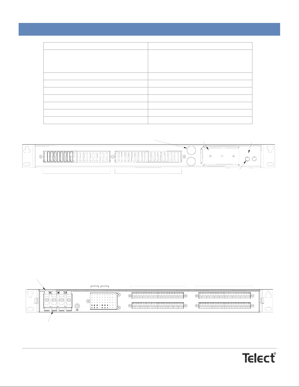
GMT output fuses are available in capacities ranging from 0.18A to 10A. GMT splash covers are optional for maximum safety when fuses blow. [Visit our website (www.telect.com) or see Page 9 for ordering GMT fuses.] The panel is delivered with “dummy” fuses in all positions.
The standard front panel includes a tri-color fuse alarm LED for each circuit (ALARM A & ALARM B):
• The ALARM LEDs are green when all installed input and output fuses are operational.
• The ALARM LED is red when any output fuse blows.
• The ALARM LED is orange when either of the input fuses blows.
The back contains input and output terminal connections (NEG connections at top; POS RTN connections below), chassis ground con-
nections, and wire-wrap pins for external alarm hookups.
Plastic Caps*
CAUTION: DO NOT REVERSE POLARITY
-A
-B
+A
Alarm Pins for Circuits
A & B
A
FAIL
RELAY
NOCNC
+B
NOCNC
Screw-Tight, Wire-Clamping
Output Terminals
-24V
TO
B
A
-48V
RTN
B
Screw-Tight, Wire-Clamping
Input Terminals
Model 06004-01 (Rear View)
Telect, Inc. • USA +1.509.926.6000 • Mexico +52.33.3836.3700
Poland +48.713.239.100 • UK +44.1489.889500 • www.telect.com
Copyright © 2006 Telect, Inc., All Rights Reserved • 130358-2 A0
* Plastic caps cover screw-tight terminals used by the manufacturer for installing
interior wiring. DO NOT REMOVE CAPS or LOOSEN CLAMPING SCREWS.
Page 2
Page 3
Plastic Caps*
CAUTION: DO NOT REVERSE POLARITY
-A
-B
+B
+A
Alarm Pins for Circuits
A & B
FA AUX RLY
FA AUX RLY
A
FA -24/48V IN
FA +GND IN
FAIL
RELAY
C
C
NO
NO
NC
NC
Screw-Tight, Wire-Clamping
Output Terminals
-24V
TO
B
A
-48V
RTN
B
Screw-Tight, Wire-Clamping
Input Terminals
* Plastic caps cover screw-tight terminals used by the manufacturer for installing
interior wiring. DO NOT REMOVE CAPS or LOOSEN CLAMPING SCREWS.
Models 06004-11 (Rear View)
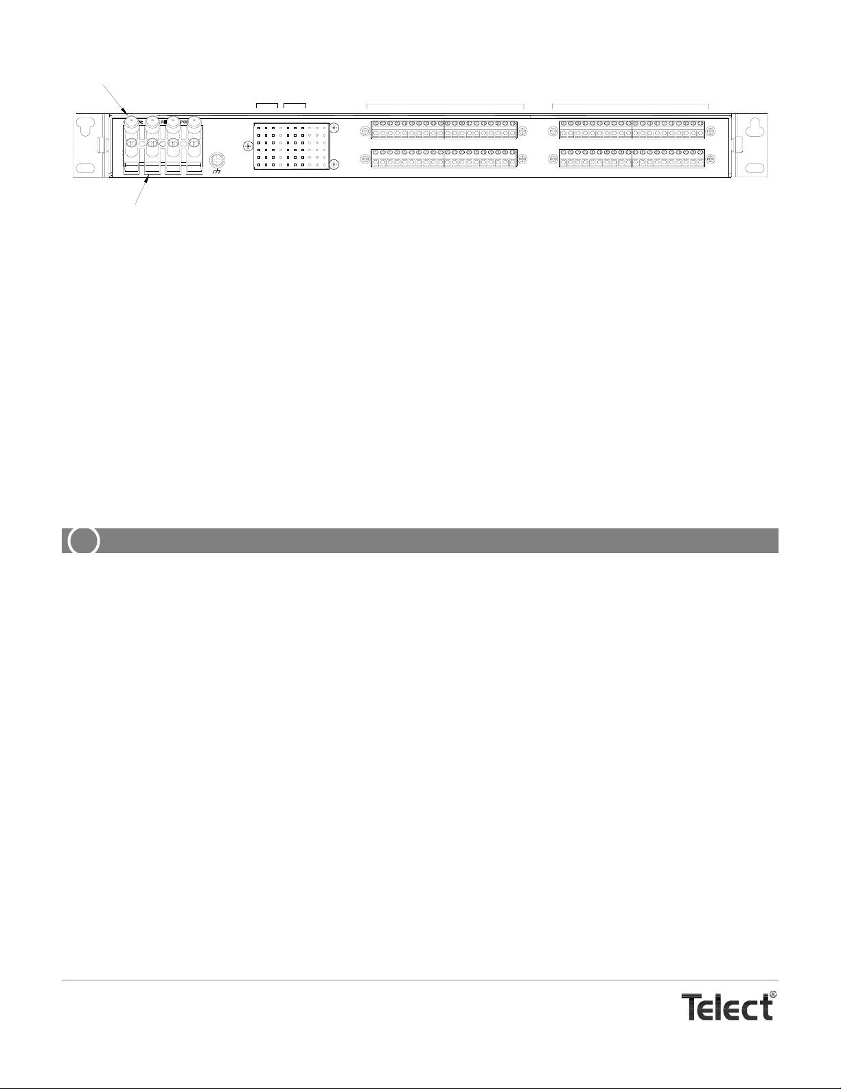
Model 06004-11 includes a fail-safe circuit. Schottky diodes are cross-connected at the input to the power distribution circuits. When
both power supplies are energized, power is balanced between the two supplies by the diodes. If one of the power supplies loses its
power or is shut down, the other supply shares its power with both outputs (A and B) through the Schottky diodes. The positive battery return circuits for A and B are common since both circuits must operate from either the A or B power source. The fail-safe feature reduces the A and B inputs to 15A maximum for each bus (total 30A per panel).
NOTE
For the Fail Safe load sharing to function properly, the capacity of each of the user-supplied external feeder fuses or breakers
must be greater than the total load of the panels A and B outputs combined. For example, if the panel’s total Load A = 10A and
Load B = 10A, then the feeder fuse for Side A and Side B must each be at least 20A.
INSTALLATION
ALERT
!
ALERT! This product must be installed within a restrict ed acce ss location whe re acce ss is through t he use of
a tool, lock and key, or other means of security, and is controlled by the authority responsible for the location.
This product must be installed and maintained only by qualified personnel.
ALERT! Verify all connections meet requirements specified in local electric codes or operating company
guidelines before supplying power. Protect this equipment with a fuse or breaker sufficient to interrupt power
levels specified under “Electrical Specifications”.
ALERT! Each panel is tested at the factory. Telect recommends, however, that you perform the testing outlined in the following installation procedure to ensure that no damage has occurred during shipping and handling. Both Sides A and B input circuits, as applicable, need to be tested.
Please read these instructions carefully before beginning installation. If you need assistance call Technical Support at 888-821-4856
(domestic calls), or 509-921-6161 (Option 2), or eMAIL us at [email protected]
1. Inspect equipment after unpacking and compare it to the packing list.
Immediately report any shipping damage, defects, or missing parts to Telect at 1-800-551-4567. Keep all documentation that
comes with your shipment.
NOTES
• Telect is not liable for shipping damage. If damaged, notify the carrier and call Telect’s Customer Service Department at
1-800-551-4567 (domestic only) or 1-509-926-6000 for further recourse.
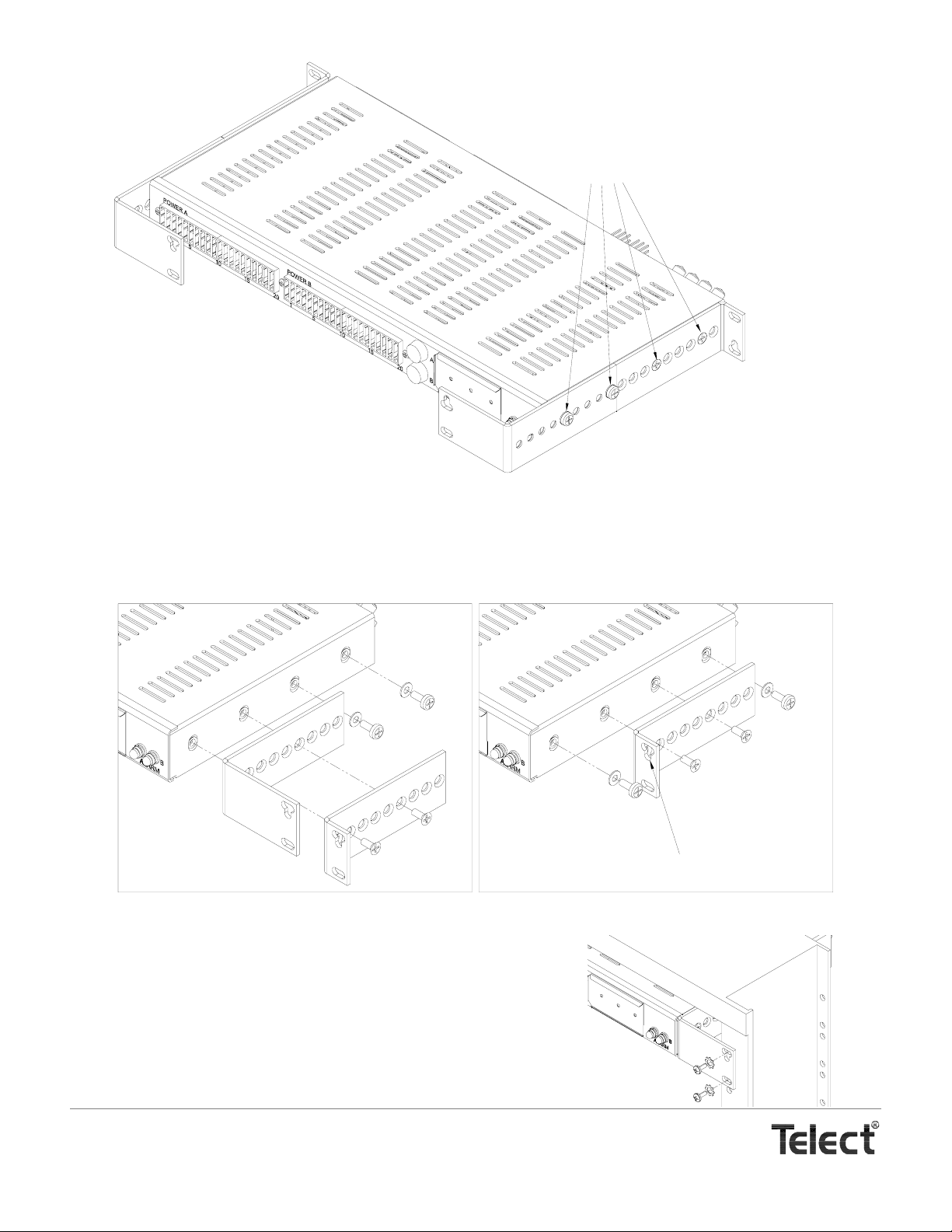
• Brackets are provided for either flush or extended [increments of 0.5 in. (12.7 mm)] mounting in a 19 in. or 23 in . rack with
either EIA or WECO spacing. For shipping purposes, both pairs of brackets are affixed to the sides of the panel.
2. Remove brackets, shown in the following illustration, from sides of panel.
Telect, Inc. • USA +1.509.926.6000 • Mexico +52.33.3836.3700
Poland +48.713.239.100 • UK +44.1489.889500 • www.telect.com
Copyright © 2006 Telect, Inc., All Rights Reserved • 130358-2 A0
Page 3
Page 4
Left Bracket
for 19-in. Rack
Remove Screws (4) on Each
Side of Panel to Remove
Brackets from Stowed Position
Right Bracket
for 23-in. Rack
Right Bracket
for 19-in. Rack
Left Bracket
for 23-in. Rack
Panel With Mounting Brackets in Stowed Position for Shipping
3. Select the proper pair of brackets and discard the other two.
4. Mount brackets to sides of panel, as shown in the following examples. Tighten screws to about 29 in.-lb (~3.3 N•m).
Panel can be mounted so that panel’s face is flush or extended in 0.5-in. (12.7 mm) increments from rack. (The clover-leaf p at-
tern on the face of the bracket points downward on the right side of the panel and upward on the left.)
Bracket for a
23-in. Rack
(Flush Mount)
Bracket for a
19-in. Rack
(Flush Mount)
Bracket Installation (Examples)
5. Locate an unused rack position and mount panel using four, 12-24 thread-cutting screws and lockwashers provided, as shown on the right. Tighten screws
to 35 in.-lb (4.29 N•m).
6. Before connecting any conductor, use a multimeter to measure the resistance
between the input terminal of each side (+A and -A for Side A; +B and -B for
Side B) at the rear corner of the panel. Expect 500Ω or more for both Side A
and Side B.
Telect, Inc. • USA +1.509.926.6000 • Mexico +52.33.3836.3700
Poland +48.713.239.100 • UK +44.1489.889500 • www.telect.com
Copyright © 2006 Telect, Inc., All Rights Reserved • 130358-2 A0
Page 4
Bracket for a
19-in. Rack
(Extended 2 in.)
Clover-Leaf Pattern Points Downward
on Right Side of Panel.
Page 5
WARNING
!
WARNING! Failure to properly ground this equipment can create hazardous conditions to installation personnel and to the equipment.
WARNUNG! Bei unsachgemäßer Erdung besteht Gefahr für das Installationspersonal und das Gerät!
¡AVISO! La conexión incorrecta a tierra puede ser peligrosa tanto para los instaladores como para el equipo.
AVERTISSEMENT! Si vous ne reliez pas correctement cet équipement à la terre, son utilisation présente des
dangers pour la personne qui l'installe ainsi que pour l'équipement.
ALERT
!
ALERT! Only use components and crimping tools approved by agencies or certifying bodies recognized in
your country or region such as Underwriter’s Laboratories (UL), TUV, etc.
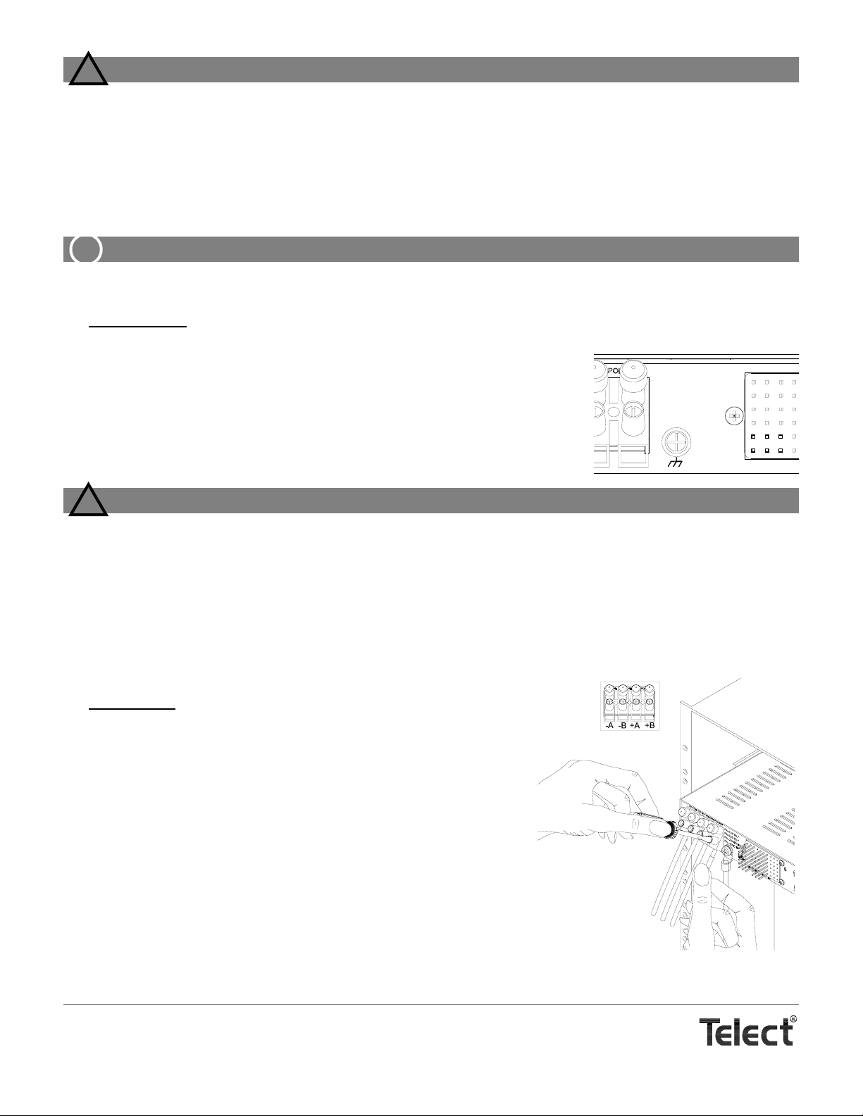
7. For ground wiring, use a listed (approved) crimping tool to attach a listed (approved), single-hole compression lug suitable for a
#10 (~5 mm) stud onto a suitable ground wire.
Ground wire should be same gauge as input wiring. Input wire size depends solely on input interruption device at the primary distribution unit (PDU).
8. If necessary, use a coarse, nonmetallic cleaning pad to clean lug and stud.
9. Telect recommends that you lightly coat anti-oxidant on lug, grounding screw, and surrounding contacting surface. Connect lug to rear panel using #10 ground provided,
shown on the right. Tighten screws to 20 in.-lb (~2.26 N•m).
FAIL
RELAY
A
C
NO
NC
WARNING
!
WARNING! Before connecting input power cables, make sure input power to panel is turned off.
WARNUNG! Vor Anschluss der Eingangsstromkabel ist sicherzustellen, dass der Eingangsstrom
ausgeschaltet ist.
¡AVISO! Antes de conectar los cables de entrada de la alimentación, compruebe que la alimentación de
entrada al panel está cortada.
AVERTISSEMENT! Avant de connecter les câbles d'entrée d'alimentation, assurez-vous que l'alimentation
électrique est coupée au panneau.
10. Make sure input power is off.
11. For input wiring
proximately
ductors.
Input conductor (14 to 6 AWG) must match or exceed the rating of the fuse or
breaker at the PDU. (Stranded wires should be tinned.)
12. Lightly coat anti-oxidant on bare conductors insert the conductors at the bottom of the screw-tight terminals, as shown on the right. Tighten screws to 16
in.-lb (1.80 N•m).
-24 Vdc and -48 Vdc always goes to -A and -B and +24 Vdc always goes to +A
and +B, depending on CO or base-station power. RTN always goes to the other terminal. For Model 06004-11 with fail-safe circuitry, make sure that RTN is
common to both Side A and B.
— wiring used as inputs to this distribution panel — strip ap-
3
/8 in. (~10 mm) of insulation from the end of suitable input con-
Important
Telect, Inc. • USA +1.509.926.6000 • Mexico +52.33.3836.3700
Poland +48.713.239.100 • UK +44.1489.889500 • www.telect.com
Copyright © 2006 Telect, Inc., All Rights Reserved • 130358-2 A0
Page 5
Page 6
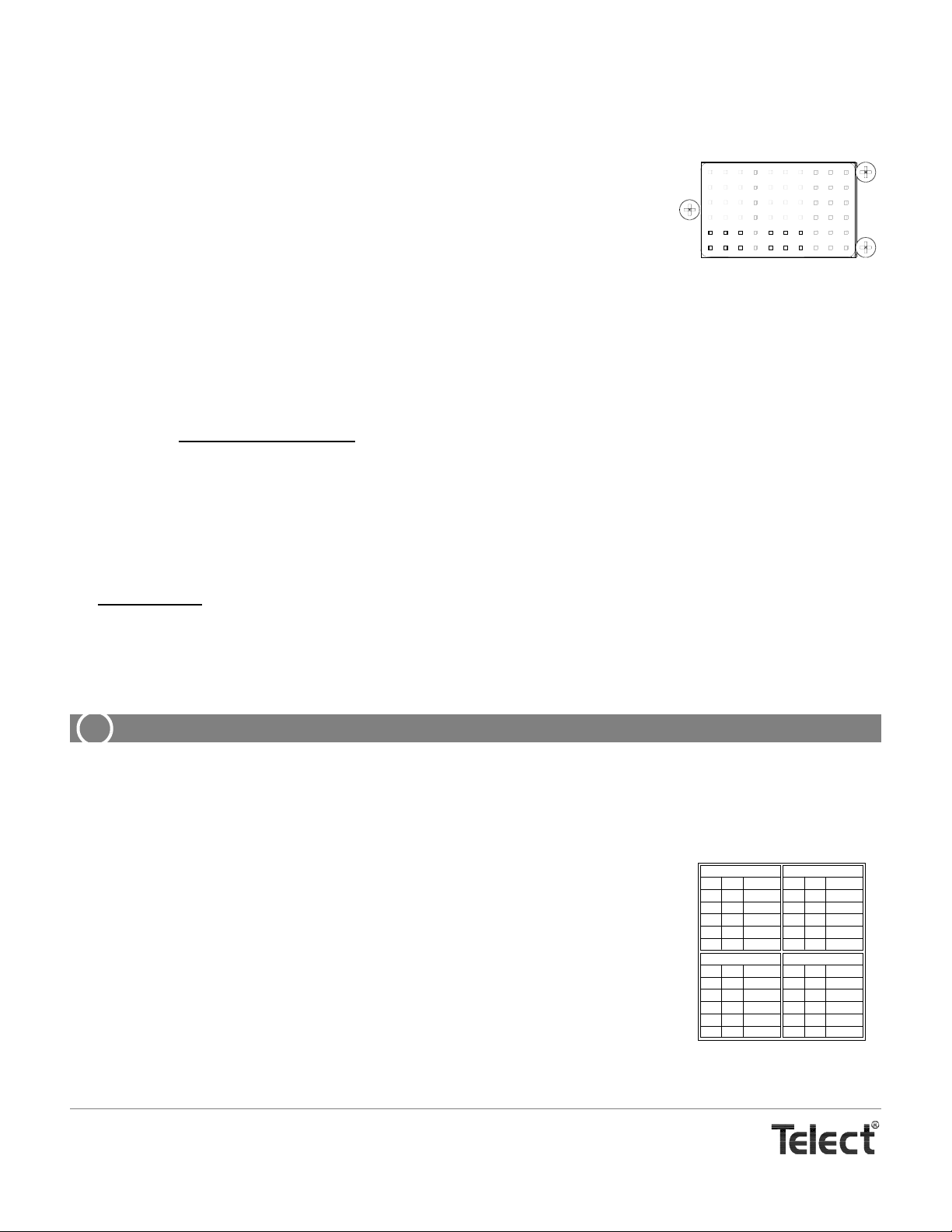
13. Make sure power is off [open breaker, dummy fuse, or vacant fuse holder at power distribution unit (PDU)] before connecting
this panel’s cables to PDU.
14. Make sure that only dummy GMT fuses are install in this panel or that the GMT fuse holders are vacant.
15. Enable fuse or breaker at PDU (25A max. for Model 06004-01; 35A max. for Model 06004-11 which contains a fail-safe circuit)
to turn on Feed A to Side A of panel.
16. Check voltage and polarity at input connectors of panel. Also, check that —
•The A LED on front of panel turns on (green).
A
B
•The B LED must remain red.
If the A LED doesn’t turn green, recheck polarity at input connectors. (Reversing input
connections will not harm the panel.) If the input power leads were reversed, the fuse fail
FAIL
RELAY
NO
C
NC
NO
C
NC
relay will fail to energize causing the normally open contacts to remain closed and normally closed contacts to remain open. If necessary, check across the FAIL RELAY alarm pins located on the rear of the panel,
and shown above.
17. On the rear of the panel, with A LED lit (normal operation) — but with B LED off (failure operation) — test the
Side-A FAIL RELAY pins:
• Expect continuity (0Ω) between Terminals C and NC.
• Expect an open circuit (∞Ω) between Terminals C and NO.
Conversely, when testing the Side-B pins
—
•Expect an open circuit (∞Ω) between Terminals C and NC.
•Expect continuity (0Ω) between Terminals C and NO.
18. Repeat Steps 15 to 17 for Feed B and observe that the B LED turns green. Across all FAIL RELAY alarm pins —
• Expect continuity (0Ω) between Terminals C and NC.
• Expect an open circuit (∞Ω) between Terminals C and NO.
19. For output wiring
, strip off ¼ in. (~7 mm) of insulation.
Like the input terminals, the output terminals are screw-tight, wire-clamping. The output terminals will accommodate 14 AWG to
6 AWG conductors. Like the output terminals, stranded wires for outputs should be tinned.
Remember: Output conductors must be rated at or above the amperage rating of the GMT fuse. For example, use no smaller
than #16 AWG output wiring for 10A output fuses. Do not exceed 8A continuous load for a 10A fuse.
ALERT
!
ALERT! GMT fuses have a small inherent electrical resistance resulting in a small inherent power loss. For
this reason, the GMT fuse manufacturer recommends that the lo ad for GMT fus es up to and including 7.5A not
exceed 80% of the fuse rating and that the load for 10A GMT fuses not exceed 70% of the fuse rating. (For example, 10A fuse x .70 = 7A max. load). Total load for all GMT outputs on each side must not exceed 20A for a
panel without a fail-safe circuit, or 15A for a panel with a fail-safe circuit.
20. Telect recommends that you lightly coat anti-oxidant on bare wires before connecting to output terminals. (NEC specifies only one conductor and load for each output terminal.) Tighten
screws to 4.5 in.-lb (0.51 N•m).
21. Connect other end of output wires to load.
22. Record circuits on designation card provided, as specified by operating company procedures.(The front side of the card is shown on the right.)
The designation card has entries for Outputs 1-10 on the front and 11-20 on the rear. Use the
left half of each side for Side A outputs and the right half for Side B outputs.
23. Make sure inputs at loads are disabled by removing all power cards or all input fuses at load
equipment. (Always follow recommended operating company guidelines when disabling load
equipment.)
INPUT FUSE
FUSE
AMP
1
2
3
4
5
INPUT FUSE
FUSE
AMP
6
7
8
9
10
CIRCUIT
CIRCUIT
INPUT FUSE
FUSE
AMP
1
2
3
4
5
INPUT FUSE
FUSE
AMP
6
7
8
9
10
CIRCUIT
CIRCUIT
Telect, Inc. • USA +1.509.926.6000 • Mexico +52.33.3836.3700
Poland +48.713.239.100 • UK +44.1489.889500 • www.telect.com
Copyright © 2006 Telect, Inc., All Rights Reserved • 130358-2 A0
Page 6
Page 7
WARNING
!
WARNING! Use only UL-listed or UL-recognized component secondary protection devices.
24. Insert the proper sizes of GMT fuses in designated fuse holders using the designation card to identify circuits. Check voltage
and polarity at input of loads.
25. After all designated GMT fuses have been installed
corresponding A or B LED will turn red; if an input fuse blows, the corresponding A or B LED will be orange or amber.
Again, test FAIL RELAY alarm pins on rear of panel. As before —
• Expect continuity (0Ω) between Terminals C and NC.
• Expect an open circuit (∞Ω) between Terminals C and NO.
26. If available, replace one of the output fuses with a blown fuse and check that the A or B LED changes to red. Check the FAIL
ALARM pins again:
• Expect an open circuit (∞Ω) between Terminals C and NC.
• Expect continuity (0Ω) between Terminals C and NO.
When finished, re-install the operable fuse.
27. Do the same with one of the input fuses. Notice that the A or B LED changes to amber. The FAIL RELA Y alarm pins will indicate
a failure condition.
28. If desired
, wire-wrap remote external audio/visual alarm indicator wires (solid copper wires, #22 to #18 AWG) to the
alarm terminals. See “Alarm Terminal Wiring,” in the next
subsection.
29. One by one, re-enable load equipment and verify proper operation.
30. Fold designation card on the score line and slip into holder
on front of panel, as shown on the right.
, check that the A and B LEDs are still green. If an output fuse blows, the
Designation Card Holder
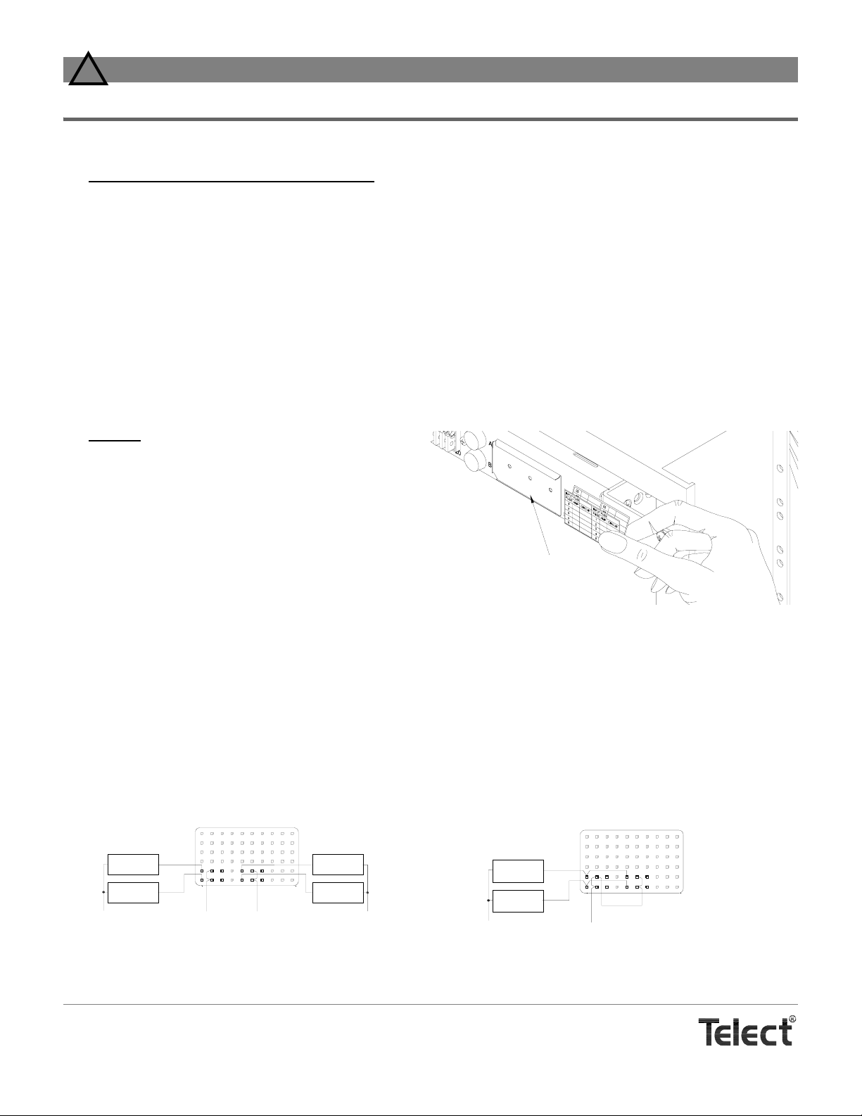
ALARM WIRING
Model 06004-01 has a standard alarm relay (FAIL RELAY) for each feed — one for Side A and one for Side B. Models 06004-11
contains the standard alarm relay plus an auxiliary relay (AUX RELAY) that can be triggered externally. All relays have two sets of
Form C dry contacts for wiring to audible and visual alarm indicators.
Audible and/or visual failure indicators can be wired to the alarm pins in several ways.
—— Standard Alarms
When an input or output fuse blows the relay is de-energized and the normally open contacts close and the normally closed contacts
open to indicate the failure.
External
Alarm Device
External
Alarm Device
NEG (or -GN D )
FAIL
RELAY
NO
CNC
+GND (or POS)
C
NO
NC
a. Separate Alarms for Side A & Side B b. Combined Alarms for Side A & Side B
A
B
External
Alarm Device
External
Alarm Device
NEG (or -GN D )
Standard Alarm Wiring
External
Alarm Device
External
Alarm Device
NEG (or -GND)
FAIL
RELAY
A
NOCNC
+GND (or POS)
B
NOCNC
Telect, Inc. • USA +1.509.926.6000 • Mexico +52.33.3836.3700
Poland +48.713.239.100 • UK +44.1489.889500 • www.telect.com
Copyright © 2006 Telect, Inc., All Rights Reserved • 130358-2 A0
Page 7
Page 8
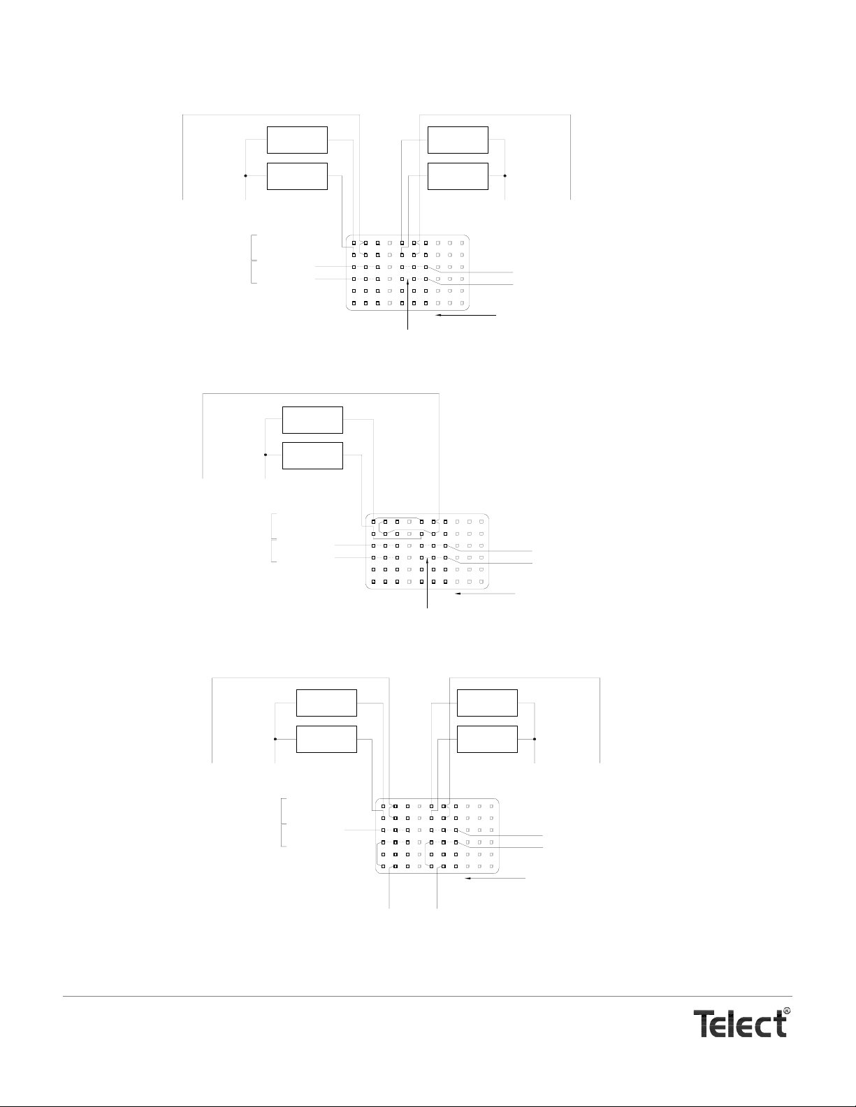
—— Auxiliary Alarms
(
)
Auxiliary alarms are triggered from either an external CO or site source or by the standard alarm relay. Like the standard relay, when
triggered, the auxiliary relay is de-energized causing the normally open contacts to close and the normally closed contacts to open.
+GND (or POS)
Auxiliary Relay
Auxiliary Relay
+GND (or POS)
NEG (or -GND)
Contacts
Trigger
Auxiliary Relay
Contacts
Auxiliary Relay
Trigger
External
Alarm Device
External
Alarm Device
FA AUX RLY
FA AUX RLY
FA -24/48V IN*
FA +GND IN**
NEG (or -GND)
FA AUX RLY
FA AUX RLY
FA -24/48V IN*
FA +GND IN**
External
Alarm Device
External
Alarm Device
NEG (or -GND)
FAIL
RELAY
A
C
NO
NO
NC
Internal Wiring
C
NC
B
* NEG (or -GND) trigger.
** POS (or +GND) trigger.
a. Separate Alarms for Side A & Side B
External
Alarm Device
External
Alarm Device
FAIL
RELAY
A
C
NO
NO
NC
Internal Wiring
C
NC
B
b. Combined Alarms for Side A & Side B
+GND (or POS)
FA -24/48V IN*
FA +GND IN**
Nomenclature is
for contacts
FA -24/48V IN*
FA +GND IN**
Nomenclature is
for contacts
* NEG (or -GND) trigger.
** POS (or +GND) trigger.
External
Alarm Device
External
Alarm Device
NEG (or -GND)+GND (or POS) +GND (or POS)
Auxiliary Relay
Contacts
Auxiliary Relay
Trigger
FA AUX RLY
FA AUX RLY
FA -24/48V IN
FA +GND IN
FAIL
RELAY
A
c. Using the Standard Alarm to Trigger Auxiliary Alarms When a Fuse Blows
Auxiliary Alarm Wiring
Telect, Inc. • USA +1.509.926.6000 • Mexico +52.33.3836.3700
Poland +48.713.239.100 • UK +44.1489.889500 • www.telect.com
Copyright © 2006 Telect, Inc., All Rights Reserved • 130358-2 A0
NO
+GND
C
NC
or POS
Page 8
NO
C
NC
External
Alarm Device
External
Alarm Device
NEG (or -GND)
B
Nomenclature is
for contacts
FA -24/48V IN*
FA +GND IN**
Page 9
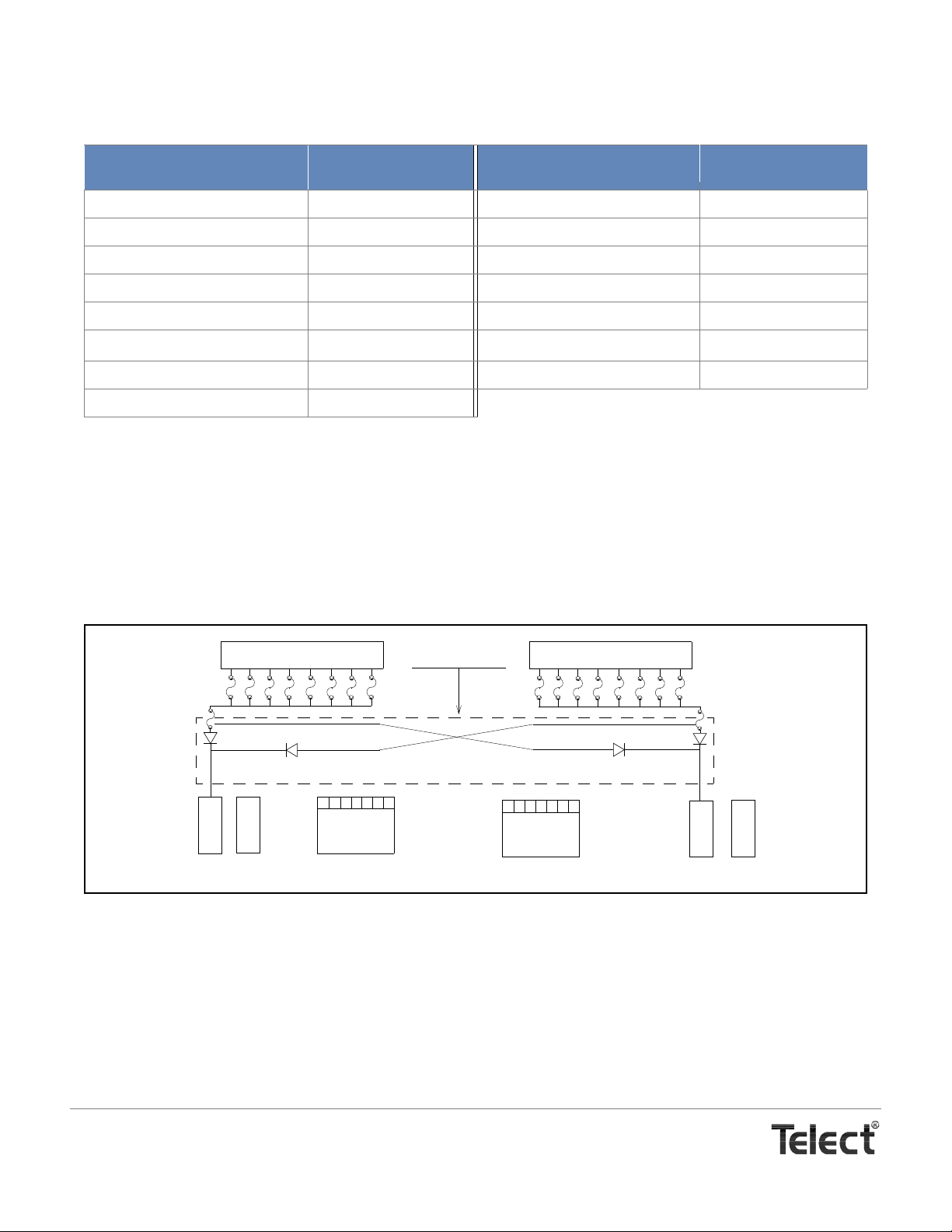
PARTS & ACCESSORIES
GMT FUSES
GMT Fuse
.18A Yellow (YEL) 130781 2.5A White/Orange (WHT/ORN) 130783
¼A Violet (VIO) 100151 3A Blue (BLU) 004012
½A Red (RED) 004001 3.5A White/Blue (WHT/BLU) 130782
¾A Brown (BRN) 004008 4A White/Brown (WHT/BRN) 004013
1A Gray (GRY) 100991 5A Green (GRN) 004014
1
1
/3A White (WHT)
1½A White/Yellow (WHT/YEL) 004011 10A Red/White (RED/WHT) 004015
2A Orange (ORN) 004002
Part Numbers
GMT Fuse
004006 7½A Black/White (BLK/WHT) 004010
1
GMT Fuse
Part Numbers
GMT Fuse
NOTES
• For service and warranty, see our telect.com website, or eMAIL inquires to [email protected], or phone us at
800-551-4567 (domestic only) or 509-926-8915.
• Low-Current GMT Fuse Panels do not require special preventive maintenance.
BLOCK DIAGRAMS
B
A
T
T
A
A POWER OUTPUT
R
T
N
GROUND
OUTPUT
A
FAIL SAFE
LOAD SHARING
B POWER OUTPUT
GROUND
OUTPUT
B
B
R
A
T
T
N
T
B
1. For dummy fuses order 101557. For GMT safety (splash/splatter) covers order 116915.
Telect, Inc. • USA +1.509.926.6000 • Mexico +52.33.3836.3700
Poland +48.713.239.100 • UK +44.1489.889500 • www.telect.com
Copyright © 2006 Telect, Inc., All Rights Reserved • 130358-2 A0
Page 9
Page 10
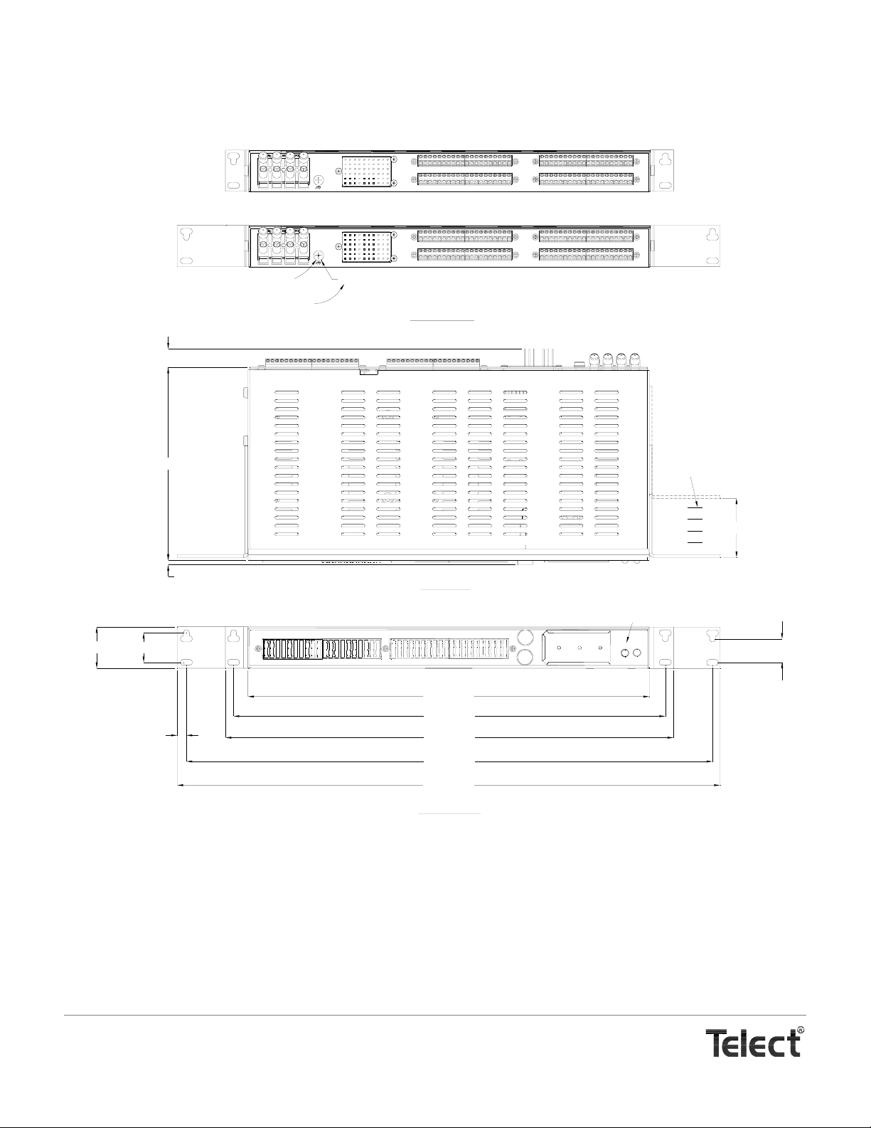
DRAWING
-24V
TO
A
FAIL
RELAY
NOCNC
NOCNC
B
A
-48V
RTN
B
Model 06004-01
1.75 [44.5]
#10-32 Panhead Screw
Min. length of lug tongue is 0.43 in. (10.8 mm)
0.77 [19.7]
8.17 [207.5]
0.19 [4.9]
1.25 [31.7]
POWER A
1
FA AUX RLY
FA AUX RLY
FA -24/48V IN
FA +GND IN
A
FAIL
RELAY
NOCNC
R0.21 [R5.4]
NOCNC
B
A
REAR VIEWS
(ROTATED)
-24V
TO
-48V
RTN
Model 06004-11
B
Face of panel can be extended
beyond rack flange by as much
as 2.50 in. (63.5 mm) in 0.5 in.
(12.7 mm).
2.50 [63.5]
TOP VIEW
"FAIL SAFE" Applies
only to Model 06004-11
POWER B
10
5
20
15
1
10
5
15
A
B
20
FAIL SAFE
A
ALARM
B
1.00 [25.4]
17.02 [432.2]
18.31 [465.1]
0.39 [9.9]
19.00 [482.6]
22.31 [566.7]
23.02 [584.6]
FRONT VIEW
Telect assumes no liability for the application or use of these products. Neither does Telect convey any license under its patent rights or the patent
rights of others. This document and the products described herein are subject to change without notice.
Telect, Inc. • USA +1.509.926.6000 • Mexico +52.33.3836.3700
Poland +48.713.239.100 • UK +44.1489.889500 • www.telect.com
Copyright © 2006 Telect, Inc., All Rights Reserved • 130358-2 A0
Page 10
Page 11

U.S. Conformity Assessment Body
Certificate of Conformity
No. 174-0923-1-0
®
Upon assessment of Technical Construction File 174-0923-1-0-TCF
it has been determined that the
Hendry Telephone Products
Power Distribution and Fan Panels
conform to the protection requirements set out in article 4 of
EMC Directive 89/336/EEC
as per EN 55022 :94 with A1 :95 & A2 :97 (class A),
EN 61000-3-2 :95, EN 61000-3-3 :95, EN 300 386 V1.2.1 :00-03,
and ETS 300 132-2;
and in accordance with the Agreement on Mutual Recognition between the United
States of America and the European Community, Sectoral Annex for EMC, this
U.S. Conformity Assessment Body hereby certifies attestations of compliance to the
EMC requirements so demonstrated.
National Technical Systems
Telect, Inc. • USA +1.509.926.6000 • Mexico +52.33.3836.3700
Poland +48.713.239.100 • UK +44.1489.889500 • www.telect.com
Copyright © 2006 Telect, Inc., All Rights Reserved • 130358-2 A0
1536 E. Valencia Drive; Fullerton, CA, USA 92831-4797; Tel (714) 879-6110; Fax (714) 879-6117
Page 11
Page 12

 Loading...