

Page 1
®
CONNECTING THE FUTURE
®
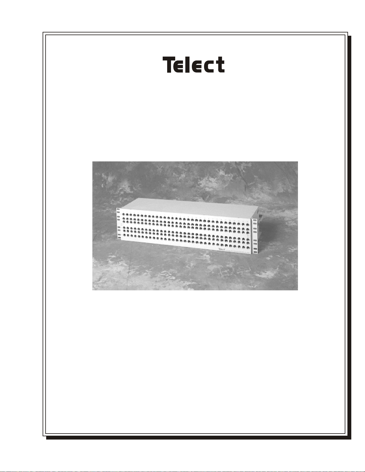
DIGITAL NETWORK INTERFACE PANEL—64 CIRCUITS
(DNI-3)
USER MANUAL
108469
Issue A Rev 2
Page 2

Digital Network Interface Panel (DNI-3) User Manual
Document Number 108469
Issue A Rev 2
Copyright© Telect, Inc., 1998, All Rights Reserved.
Telect and Connecting the Future are registered trademarks of Telect, Inc., 1730 N. Madson St., Liberty Lake,
Washington 99019. Twist Lok™ is a trademark of Telect, Inc.
Telect’s Twist Lok™ jack is protected by U.S. patent 5,209,678.
Note:
Telect assumes no liability from the application or use of these products. Neither does Telect convey any license under its patent rights nor the patent rights of others. This document and the products described herein are subject to
change without notice.
ii
108469 Issue A Rev 2
Page 3

1 Descriptions
Digital Network Interface Panel .................................................. 1-1
Capabilities ............................................................................ 1-1
Features.................................................................................. 1-1
System-Level Applications.......................................................... 1-2
Main Assemblies.......................................................................... 1-2
Physical Specifications ................................................................1-2
2 Installation
Installation Considerations .......................................................... 2-1
Location and Space................................................................ 2-1
Tools and Equipment.............................................................2-2
Inspection..................................................................................... 2-3
Installation Procedure ..................................................................2-3
Contents
3 Electrical Operation
Data Signals................................................................................. 3-1
4 User Functions
In-Service Patching...................................................................... 4-1
Out-Of-Service Patching.............................................................. 4-2
Looping........................................................................................ 4-3
Monitoring................................................................................... 4-3
Issue A Rev 2 108469 Telect, Inc.
iii
Page 4

5 Service
Owner Maintenance.....................................................................5-1
In Case Of Difficulty ................................................................... 5-1
In-Warranty Service..................................................................... 5-1
Out-Of-Warranty Service............................................................. 5-2
Repacking For Shipment ............................................................. 5-2
iv
Telect, Inc. 108469 Issue A Rev 2
Page 5
1 Descriptions
DIGITAL NETWORK INTERFACE PANEL
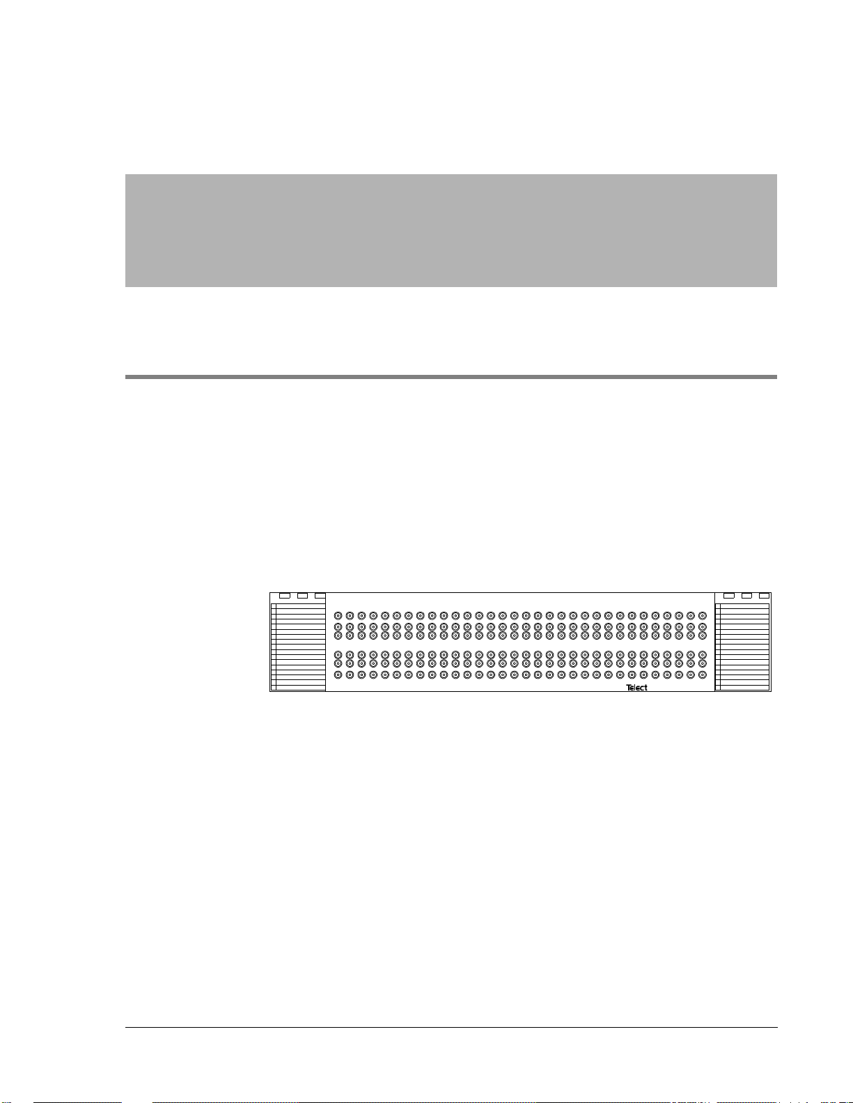
Telect’s DNI-3 is a multifunction support panel for DS3 telecommunications networks. It is an accessible and centralized interconnect point between digital cross-connect systems (DCSs) and central office network elements (NEs).
The DNI-3 panel serves as a platform for circuit configuration changes,
maintenance activities, and troubleshooting procedures. The DNI-3 becomes an extension of the DCS backplane that provides complete circuit
access, thus removing the risk of interrupting DCS operations.
1
2
3
4
5
6
7
8
9
10
11
12
13
14
15
16
Capabilities
Features
1 2 3 4 5 6 7 8 9 1011121314151617181920212223242526272829303132
M
O
I
NE-2
NE-1
O
I
M
®
®
1
M
2
3
4
O
5
I
6
7
NE-2
8
NE-1
9
O
10
11
I
12
13
M
14
15
16
• High circuit densities (up to 1280 coax cables per panel)
• Efficient circuit migration for system expansion
• Quick circuit patching, troubleshooting, and monitoring
• Compatability with all DS3, STS1, and STS3 signal types and system
management software
• Mini-WECO Twist Lok™ jacks (TLJs)
• Circuit designation labels
• Hinged designation holders
Issue A Rev 2 108469 Telect, Inc.
1-1
Page 6
Descriptions DNI-3 User Manual
SYSTEM-LEVEL APPLICATIONS
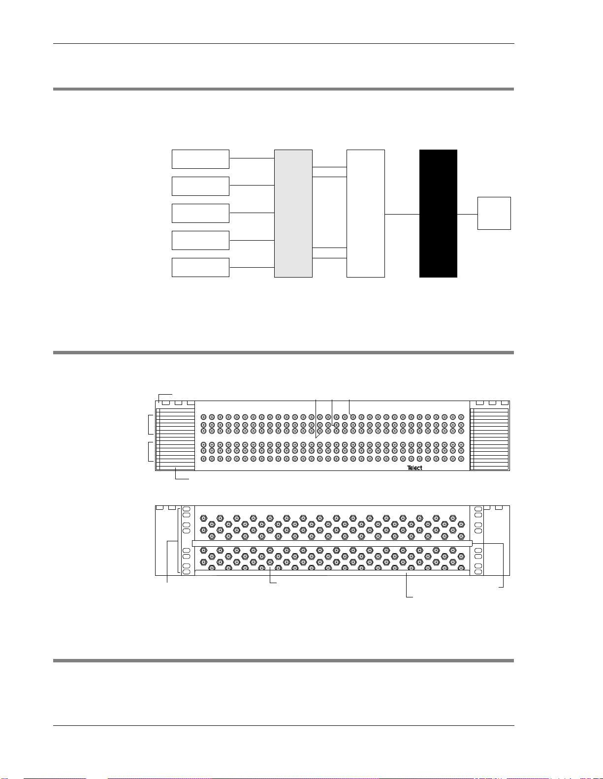
This illustration shows a DNI-3 within a typical telecommunications network.
Digital Switch
1:0 DCS
Channel Banks
Loop MUX
MAIN ASSEMBLIES
Hinged Designation Holder
1
2
3
Network Element 2
Network Element 1
4
5
6
7
8
9
10
11
12
13
14
15
16
ORBs
DNI-1
3:1
DCS
DNI-3 FOTS
DS1 Cables DS1 Cables DS3 Cable
Mini-WECO Twist Lok Jacks
Out Monitor
In
1 2 3 4 5 6 7 8 9 1011121314151617181920212223242526272829303132
M
O
I
NE-2
NE-1
O
I
M
Circuit Designation Label
FRONT PANEL
®
®
1
M
2
3
4
O
5
I
6
7
NE-2
8
NE-1
9
O
10
11
I
12
13
M
14
15
16
EIA/WECO
Mounting Spaces
PHYSICAL SPECIFICATIONS
H x W x D: 5.25 x 23.0 x 10.0 (inches); 13.3 x 58.4 x 25.4 (cm)
Weight: 30 lb (13.6 kg)
1-2
Telect, Inc. 108469 Issue A Rev 2
BNC or TNC Termination Point
REAR PANEL
1234567891011121314151617181920212223242526272829303132
Tie-Down Bar
Wire Management Tray
Page 7
2 Installation
INSTALLATION CONSIDERATIONS
Location and Space
The DNI-3 panel mounts flush into both unequal-flange and equal-flange
(EIA or WECO) 23" (58.4 cm) network bays. The primary limiting factor
of a DNI-3 rack configuration is the number of cables a network bay can
accommodate. (The DNI can accommodate 1280 coax cables.)
NOTE
Telect recommends a maximum of 14 DNI-3 panels per bay, regardless of
bay capacity, for easy access and adequate room for cable routing.
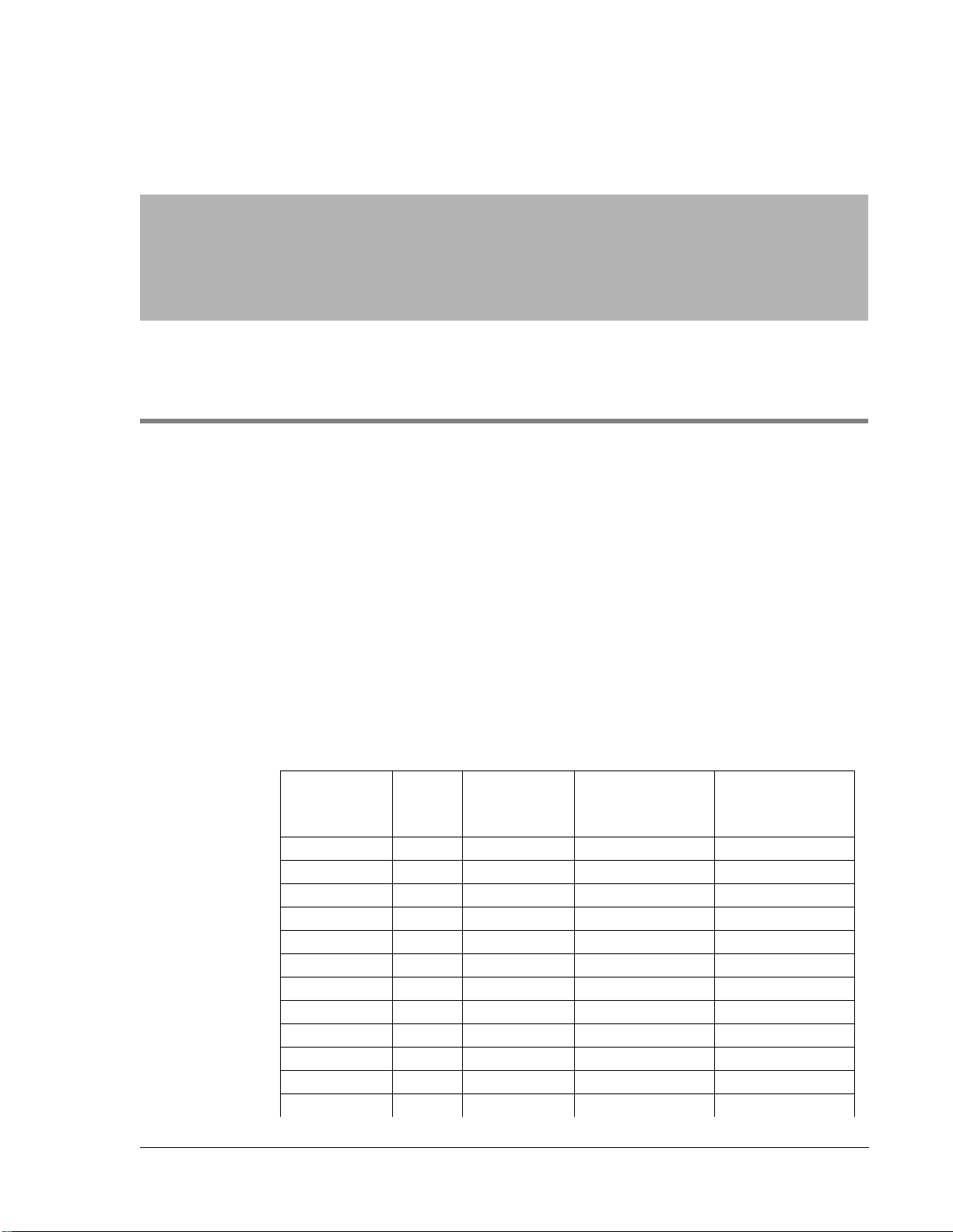
Here are the DNI-3 space requirements:
DCS
Terminations
1–32 1 128 1.64 3
33–64 2 256 3.28 6
65–96 3 384 4.92 9
97–128 4 512 6.55 12
129–160 5 640 8.19 15
161–192 6 768 9.83 18
193–224 7 896 11.47 21
225–256 8 1024 13.11 24
257–288 9 1152 14.75 27
289–320 10 1280 16.38 30
321–352 11 1408 18.02 33
353–384 12 1536 19.66 36
Issue A Rev 2 108469 Telect, Inc.
Panels Total Cables
Cable Space
Needed per Side
of Bay (in.
2
EIA Bay Spaces
)
Required
2-1
Page 8
Installation DNI-3 User Manual
DCS
Terminations
385–416 13 1664 21.30 39
417–448 14 1792 22.94 42
449–480 15 1920 24.58 45
481–512 16 2048 26.21 48
513–544 17 2176 27.85 51
545–576 18 2304 29.49 54
577–608 19 2432 31.13 57
609–640 20 2560 32.77 60
641–672 21 2688 34.41 63
673–704 22 2816 36.04 66
705–736 24 2944 37.68 69
737–768 24 3072 39.32 72
769–800 25 3200 40.96 75
Panels Total Cables
Cable Space
Needed per Side
of Bay (in.
2
EIA Bay Spaces
)
Required
In the above table, the first shaded row is the capacity for a 7-ft bay. The
second shaded row is the capacity for an 8-ft bay; the last shaded row is for
an 11.5-ft bay.
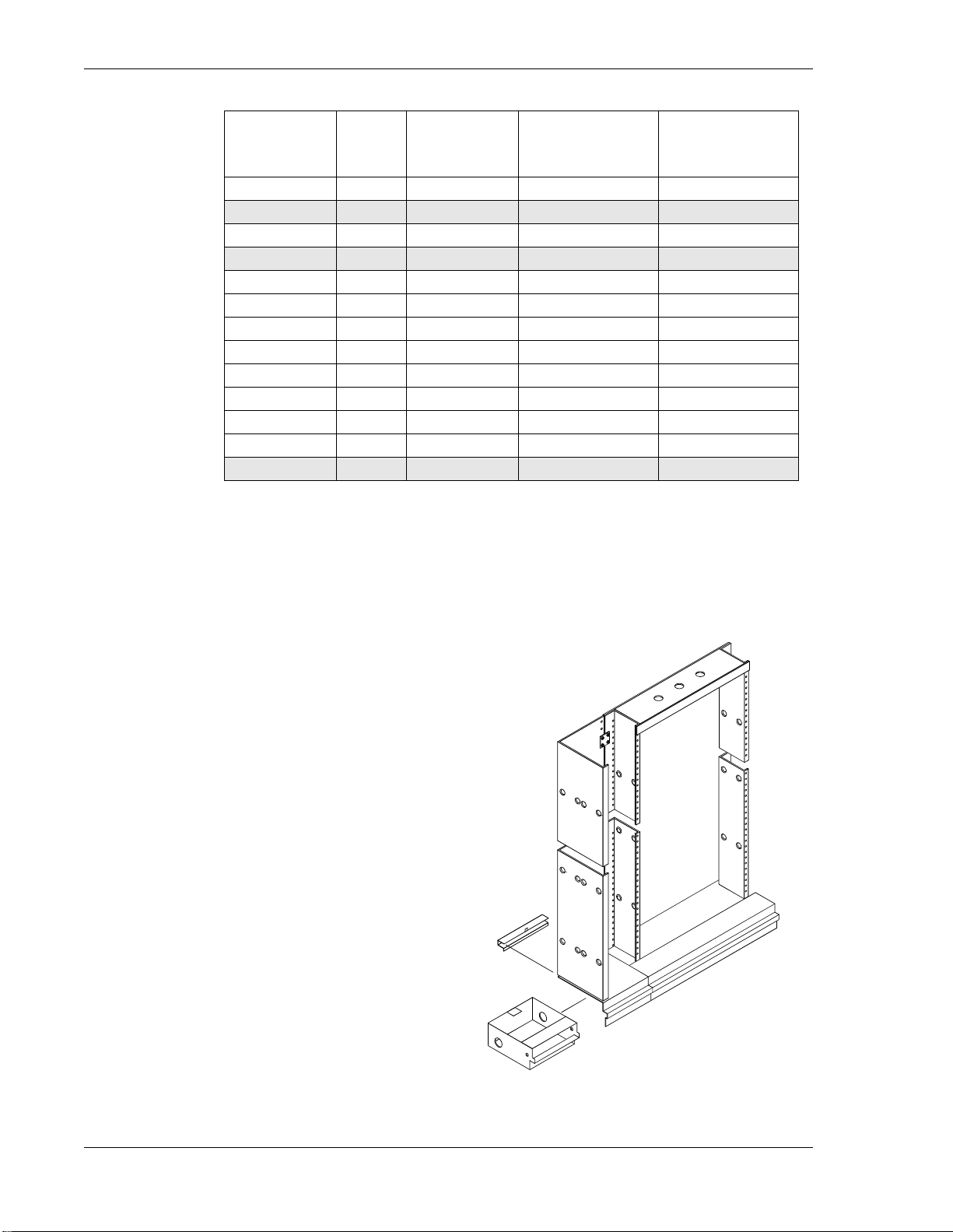
Network Bay Extender Panel
Each network bay extender
panel provides 81 square
inches (522.5 square cm) of
cable routing space (enough
for 1280 RG59 cables). The
panel comes with nine cable
management brackets that secure and channel the circuit
cables. Telect recommends
two extender panels for each
fully provisioned DNI-3 network bay. This provides adequate cable routing space for
cables going to and coming
from the DNI-3 network bay.
Tools and Equipment
No special tools or equipment are required.
Extender
Panel
Existing
Network
Bay
2-2
Telect, Inc. 108469 Issue A Rev 2
Page 9

DNI-3 User Manual Installation
INSPECTION
Compare the contents of the DNI-3 shipping container with the packing
list. Call Telect if you are missing anything.
NOTE
Telect is not liable for shipping damage.
If the shipping container is damaged, keep it for the carrier’s inspection.
Notify the carrier and call Telect’s Customer Service Department:
1-800-551-4567 or 1-509-926-6000
Keep the container until you have checked equipment operation. If you experience any kind of problem, call Telect’s Customer Service Department.
Use the original, undamaged container if you are instructed to return the
DNI-3 to Telect.
INSTALLATION PROCEDURE
Step Action
1. Align the DNI-3 chassis mounting holes with the mounting holes of
the network bay.
2. Insert four 24 x 1/2" mounting screws (two on each side) into the
mounting holes and securely tighten them.
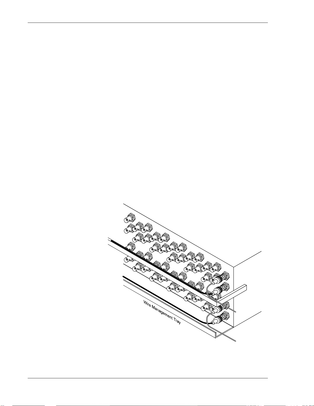
3. Route the DCS IN cables to one side of the network bay. Tie-wrap
the cables in place within the extender panel cable management
brackets.
4. Starting at the lowest DNI-3 panel and working upward, connect
the DCS IN cables to the NE-1 IN termination points on the rear of
the DNI-3 panels.
5. Secure the DCS IN cables to the wire management tray via the tie-
down slots.
6. Route the DCS OUT cables to the opposite side of the network bay.
Tie-wrap the cables in place within the extender panel cable management brackets.
Issue A Rev 2 108469 Telect, Inc.
2-3
Page 10
Installation DNI-3 User Manual
n
7. Starting at the lowest DNI-3 panel and working upward, connect
the DCS OUT cables to the NE-1 OUT termination points on the
rear of the DNI-3 panels.
8. Secure the DCS OUT cables to the wire management tray via the
tie-down slots.
9. Route the NE IN cables to the same side of the network bay as the
DCS IN cables. Tie-wrap the cables in place within the extender
panel cable management brackets.
10. Starting at the lowest DNI-3 panel and working upward, connect
the NE IN cables to the NE-2 IN termination points on the rear of
the DNI-3 panels.
11. Secure the NE IN cables to the tie-down bar.
12. Route the NE OUT cables to the same side of the network bay as
the DCS OUT cables. Tie-wrap the cables in place within the extender panel cable management brackets.
13. Starting at the lowest DNI-3 panel and working upward, connect
the NE OUT cables to the NE-2 OUT termination points on the rear
of the DNI-3 panels.
14. Secure the NE OUT cables to the tie-down bar.
IN
IN
Tie-Dow
Bar
OUT
2-4
Telect, Inc. 108469 Issue A Rev 2
OUT
Page 11
3 Electrical Operation
DATA SIGNALS
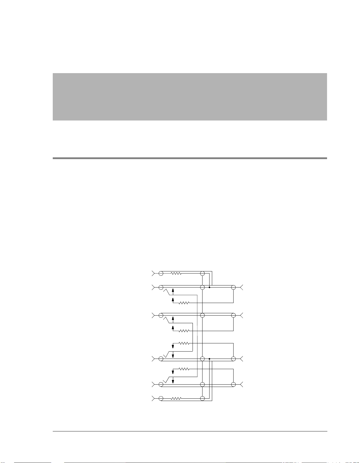
The DCS circuit cables terminate at the lower pair of term ination points on
the rear of the DNI-3 panel, labeled NE-1. The OUT cable connects to the
upper NE-1 termination point and the IN cable connects to the lower NE-1
termination point.
The NE circuit cables terminate at the upper pair of termination points on
the rear of the DNI-3 panel, labeled NE-2. The OUT cable connects to the
upper NE-2 termination point and the IN cable connects to the lower NE-2
termination point.
Internally, the DCS circuits and the NE circuits are cross-connected.
M
O
NE-2
I
O
NE-1
I
M
Issue A Rev 2 108469 Telect, Inc.
R2
R2
R1
R1
R1
R1
O
NE-2
I
R1 = 75Ω, ¼W
R2 = 768Ω, ¼W
O
NE-1
I
RearFront
3-1
Page 12

Electrical Operation DNI-3 User Manual
Inserting a Mini-WECO patch cord into the upper monitor Twist Lok Jack
(TLJ) on the front of the DNI-3 panel accesses the NE circuit. Inserting a
Mini-WECO patch cord into the lower monitor TLJ on the front of the
DNI-3 panel accesses the DCS circuit.
3-2
Telect, Inc. 108469 Issue A Rev 2
Page 13

4 User Functions
IN-SERVICE PATCHING
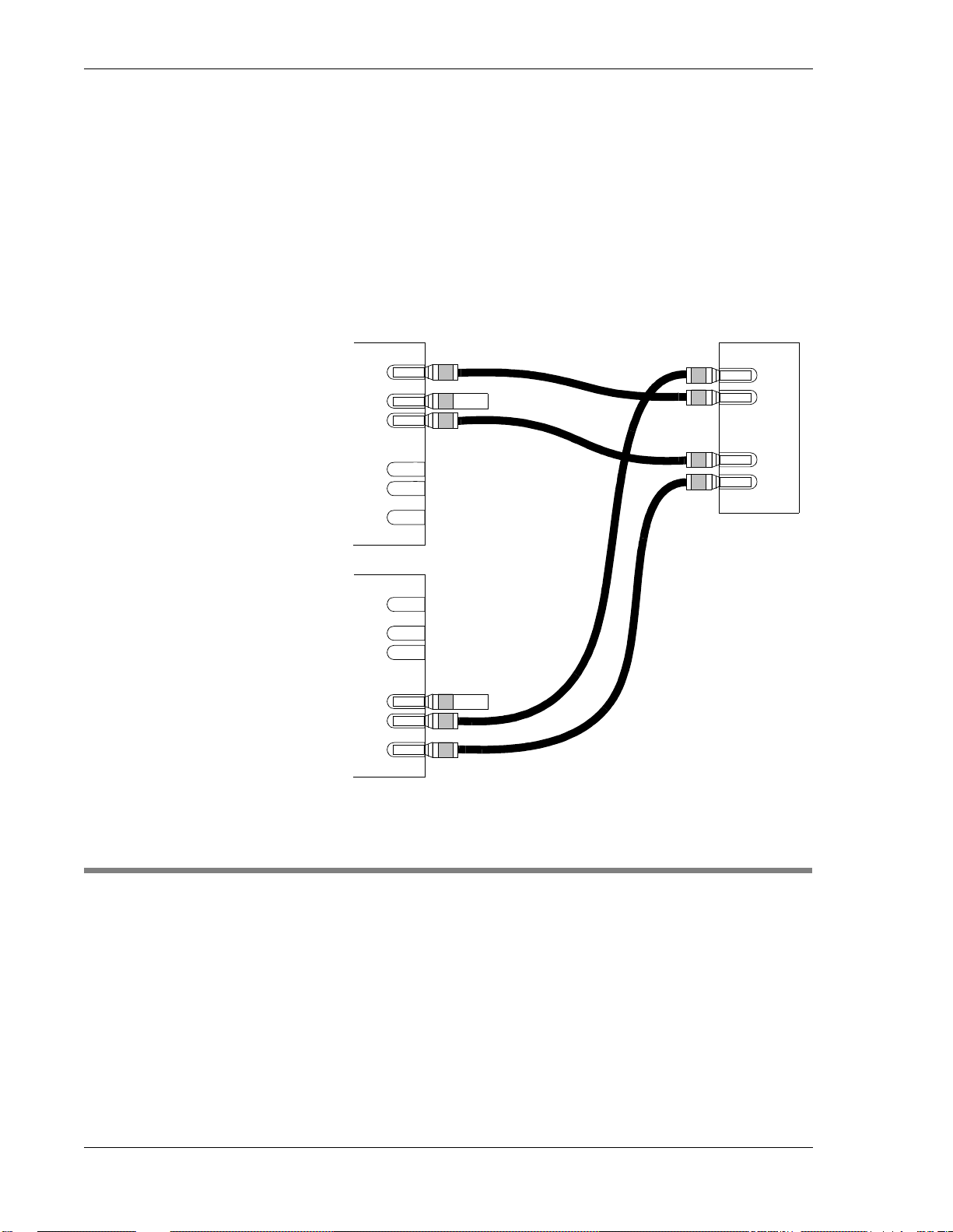
To temporarily connect an NE or DCS circuit to an alternate DCS or NE
circuit on the same or a different DNI-3 panel or DSX without disrupting
service, follow the steps below, using the Twist Lok Jacks (TLJs) on the
front of the appropriate DNI-3 panels and the following additional equipment:
• Four Mini-WECO patch cords (Mini-WECO plug at each end)
• Two 75-ohm Mini-WECO terminating plugs
• One dual bridging office repeater (BOR), or two single BORs
Step Action
1. Using one Mini-WECO patch cord:
a. Insert the plug of one end into BOR position 1, INPUT.
b. Insert the plug of the other end to the monitor TLJ at the first lo-
cation.
2. Using a second Mini-WECO patch cord:
a. Insert the plug of one end into BOR position 1, OUTPUT.
b. Insert the plug of the other end into the IN TLJ at the second lo-
cation.
3. Using a third Mini-WECO patch cord:
a. Insert the plug of one end into BOR position 2, INPUT.
b. Insert the plug of the other end into the monitor TLJ at the sec-
ond location.
Issue A Rev 2 108469 Telect, Inc.
4-1
Page 14
User Functions DNI-3 User Manual
4. Using a fourth Mini-WECO patch cord:
a. Insert the plug of one end into BOR position 2, OUTPUT.
b. Insert the plug of the other end into the IN TLJ at the first loca-
tion.
5. Insert a Mini-WECO terminating plug into the OUT TLJ at the first
location.
6. Insert a second Mini-WECO terminating plug into the OUT TLJ at
the second location.
1st
Location
DNI-3s
2nd
Location
M
O
I
O
I
M
M
O
I
O
I
M
Output
Pos 1
Input
Output
Pos 2
Input
BOR
OUT-OF-SERVICE PATCHING
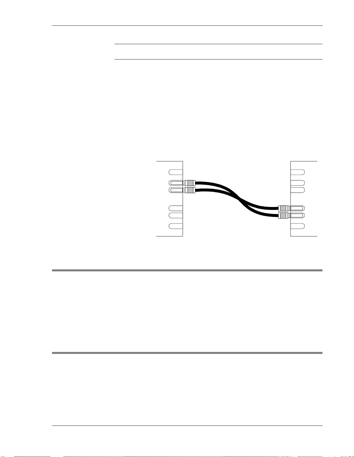
To temporarily connect an NE or DCS circuit to an alternate DCS or NE
circuit on the same or a different DNI-3 panel or DSX when service has
been disrupted, follow the steps below, using the TLJs on the front of the
appropriate DNI-3 panels and two Mini-WECO patch cords (Mini-WECO
plug at each end).
4-2
Telect, Inc. 108469 Issue A Rev 2
Page 15
DNI-3 User Manual User Functions
Step Action
1. Using one Mini-WECO patch cord:
a. Insert the plug of one end into the IN TLJ at the first location.
b. Insert the plug of the other end into the OUT TLJ at the second
location.
2. Using a second Mini-WECO patch cord:
a. Insert the plug of one end into the OUT TLJ at the first location.
b. Insert the plug of the other end into the IN TLJ at the second lo-
cation.
O
I
LOOPING
MONITORING
O
I
To temporarily loop an NE or DCS OUT port to its IN port, use the TLJs
on the front of the DNI-3 panel and a Mini-WECO looping plug.
Insert the looping plug into both the IN and OUT TLJs on the front of the
DNI-3 panel for looping either the NE (NE-2) or the DCS (NE-1) circuit.
Use the TLJs on the front of the DNI-3 panel and the following additional
equipment:
• Mini-WECO patch cord (Mini-WECO plug at each end)
•Test set
Issue A Rev 2 108469 Telect, Inc.
4-3
Page 16

User Functions DNI-3 User Manual
Step Action
1. To monitor the NE circuit outputs, insert a Mini-WECO patch cord
into the NE (upper) Monitor TLJ.
To monitor the DCS circuit outputs, insert a Mini-WECO patch
cord into the DCS (lower) Monitor TLJ.
2. Connect the other end of the the patch cord to the test set to complete your connection and perform monitoring.
4-4
Telect, Inc. 108469 Issue A Rev 2
Page 17

5 Service
OWNER MAINTENANCE
Telect’s DNI-3 does not need preventive maintenance.
IN CASE OF DIFFICULTY
If problems occur after initial installation, check all cable connections and
the installation instructions in Section 2.
IN-WARRANTY SERVICE
Contact your Telect equipment distributor, or call a Telect Customer Service Representative:
1-800-551-4567
1-509-926-6000
Telect will repair or replace defective products within the limits of the warranty. See “Repacking for Shipment” in this section.
NOTE
Call a Customer Service Representative for a Return Material Authorization (RMA) before returning any equipment.
Issue A Rev 2 108469 Telect, Inc.
5-1
Page 18

Service DNI-3 User Manual
OUT-OF-WARRANTY SERVICE
The procedure for out-of-warranty service is the same as for in-warranty
service, except that Telect charges a processing fee, and you must s ubmit a
Purchase Order along with a Return Material Authorization (RMA) before
returning equipment. Call a Customer Service Representative for help getting these forms.
The processing fee guarantees a repair estimate and is credited against actual material and labor costs.
REPACKING FOR SHIPMENT
Step Action
1. Tag the equipment showing owner’s name, address, and telephone
number, together with a detailed description of the problem.
2. Use the original shipping container if possible. If you do not have
it, package the equipment in a way to prevent shipping damage. Include the RMA inside the container.
3. Insure the package.
NOTE
Telect is not liable for shipping damage.
5-2
Telect, Inc. 108469 Issue A Rev 2
Page 19

Page 20

Telect, Inc.
1730 N. Madson St.
P.O. Box 665, Liberty Lake, WA 99019
509-926-6000, 800-551-4567, Fax 509-926-8915
E-mail: [email protected] Internet: http://www.telect.com
 Loading...