

Page 1
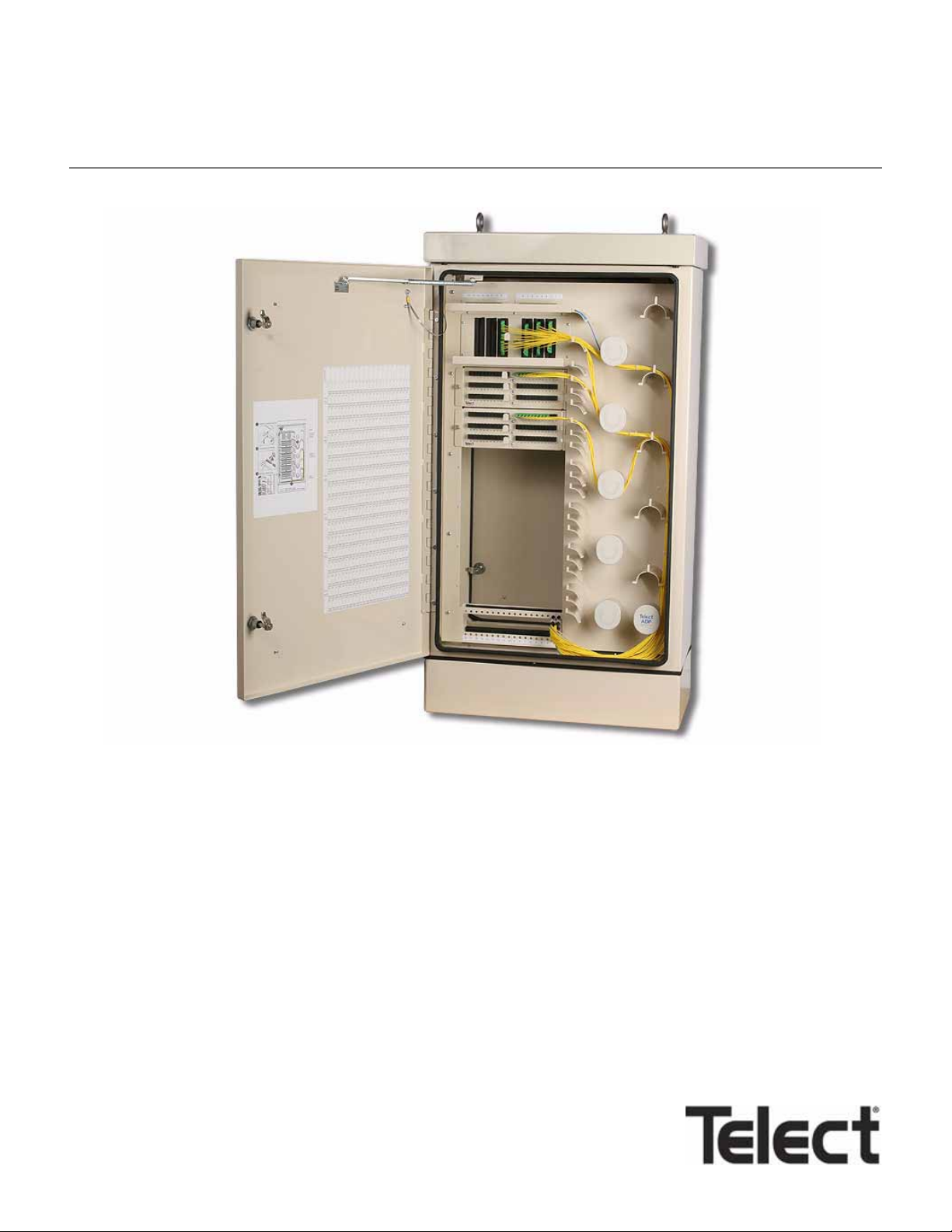
MetroLinks Distribution Cabinet (MDC-CB)
User Manual 131220 A0
Page 2

Page 3

Content s
1. Description
MDC-CB Without Rear Compartment Splicing................................................................................................ 1-3
MDC-CB With Rear Compartment In-Cabinet Splicing ....................................... ... ... ... .... ... ........................... 1-4
Front Compartment Cross Connections ......................................................................................................... 1-5
Features ......................................................................................................................................................... 1-6
Benefits .......................................................................................................................................................... 1-6
Specifications & Capacities .................................................... ... ... ... .... ........................................................... 1-6
2. Cabinet Installation
Installation Considerations ............................................................................................................................. 2-1
Pre-Installation ............................................................................................................................................... 2-1
Location & Layout — ................................ ... ... .... ... ....................................... ... ... ... .... ... ... ........................ 2-1
Tools & Equipment — ............................................................................................................................. 2-3
Inspection ................................. .................................................................... .................................................. 2-3
Installation Procedure ..................................................................................................................................... 2-3
3. Cabling Without In-Cabinet Splicing
Feeder Cable Installation ............................................................................................................................... 3-1
Patch Module & Distribution Cable Installation .............................................................................................. 3-4
4. Cabling With In-Cabinet Splicing
Splice Box Installation ........................ ... .... ... ... ... ....................................... ... ... .... ... ... ... .... .............................. 4-1
Patch Module Installation ............................................................................................................................... 4-1
Feeder Cable Installation ............................................................................................................................... 4-3
Distribution Cable Installation ......................................................................................................................... 4-9
Routing Feeder & Distribution Loose Tubing .................................................................................................4-11
5. Cross Connections
6. Service
Technical Support ........................................................................................................................................... 6-1
In-Warranty Service ........................................................................................................................................ 6-1
Out-Of-Warranty Service ................................................................................................................................ 6-1
Repacking For Shipment . ... ... ... .... ... ... ... .... ... ... ....................................... ... ... ... .... ... ... ... .... ... ........................... 6-2
Cleaning Patch Module Connectors & Adapters ............................................................................................ 6-2
7. Accessories
Standard Accessories ...................................................... ... ....................................... ... .... .............................. 7-1
In-Cabinet Splicing Accessories ............................ .... ... ... ... .... ... ... ... .... ... ... ... ... .... ... ... ..................................... 7-3
Telect, Inc. • USA +1.509.926.6000 • Mexico +1.52.33.3836.3700
Poland +1.48.713.239.100 • UK +1.44.1489.889500 • www.telect.com
Copyright © 2002 Telect, Inc., All Rights Reserved • Telect Publication 125147-3 A0
Page 4

Telect, Inc. • USA +1.509.926.6000 • Mexico +1.52.33.3836.3700
Poland +1.48.713.239.100 • UK +1.44.1489.889500 • www.telect.com
Co
pyright © 2006 Telect, Inc., All Rights Reserved
Page iv
Page 5
1. Description
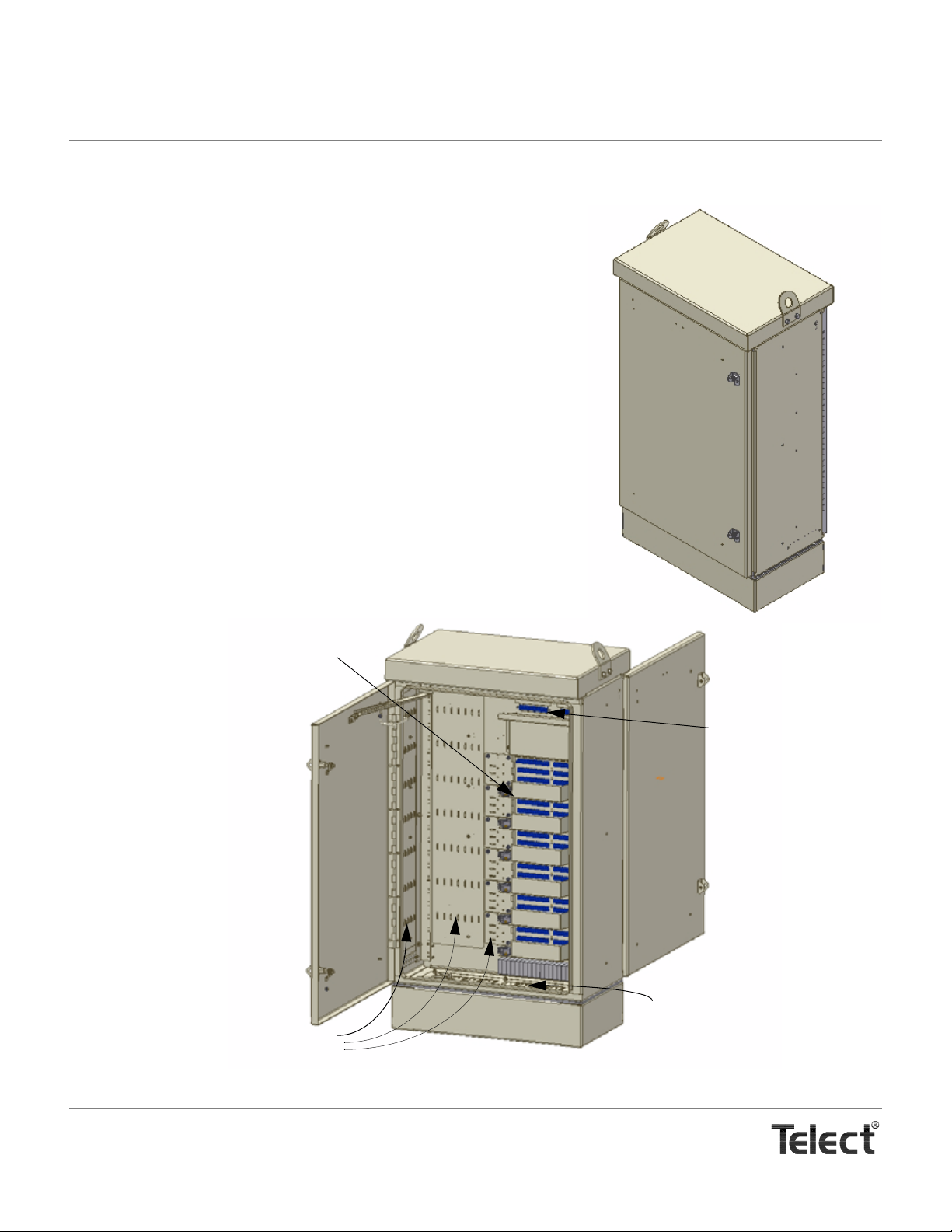
Distribution Adapters
Feeders to Front
Compartment
Feeder & Distribution
Cable Entrances
Lances for Anchoring Cable
& Subunits
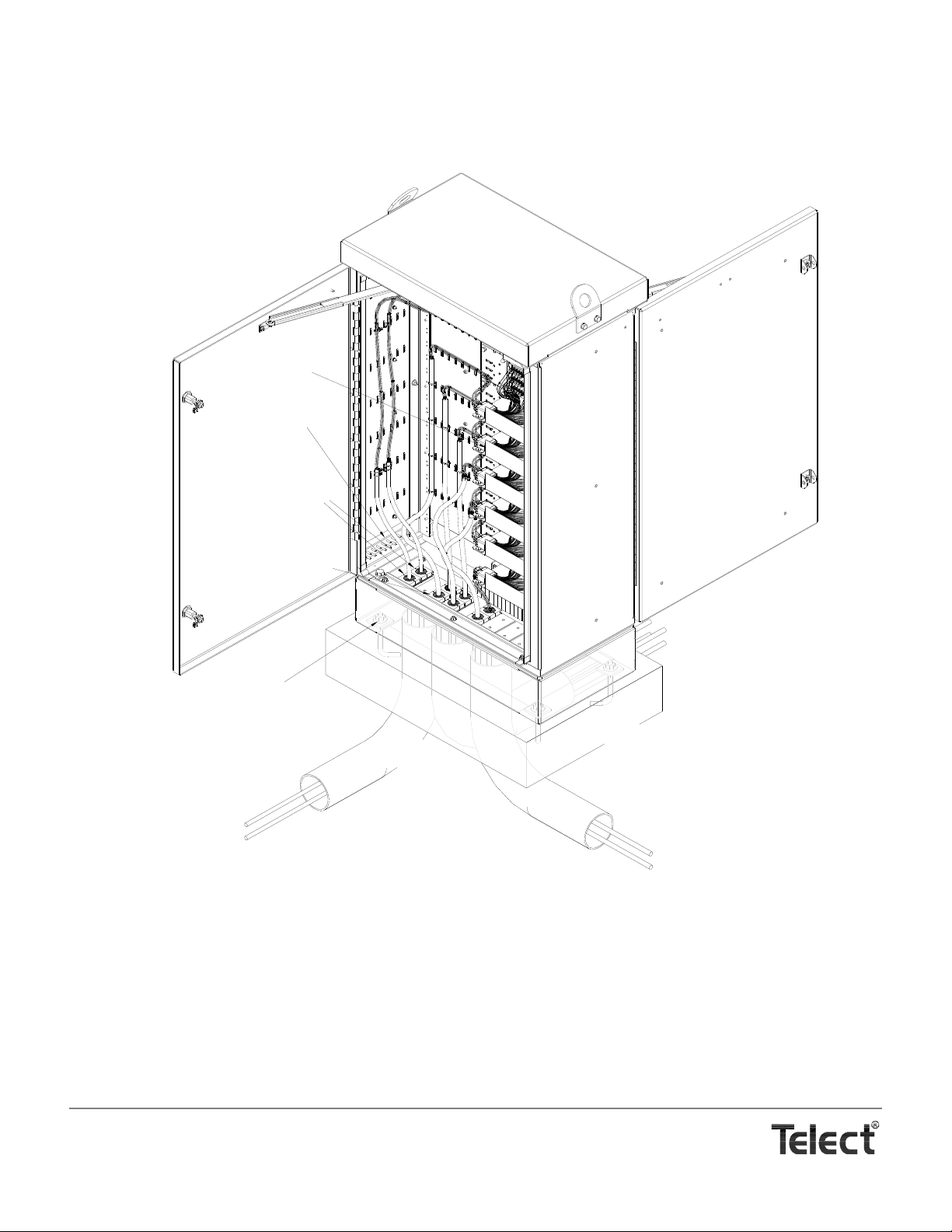
MDC-CB Without In-Cabinet Splicing (Rear Corner View)
Cabinet
Base
Telect’s MDC-CB is an indoor/outdoor fiber telecommunication distribution cabinet. The cabinet h ouses T elect’s bulkhead-style Patch Modules to
handle optical signal distributio n between a CO and the network edge. A
single MDC-CB cabinet with up to six Telect Patch Modules can provide
distribution service to 432 homes, offices and/or nodes.
The weather-tight, heavy-gauge, light-weight aluminum cabinet is almond with
two lockable doors — both doors have wind stays. OSP feeder and distribution
cable enter through weather-tight cable clamps at the bottom of the rear compartment:
Illustrations that follow depict open-door views of MDC-CB cabinets with and
without in-cabinet splicing.
Along with the cabinet, Telect includes a footprint template which is also the isolation pad, two cable entrance clamps for two feeder cables between
mm) and 1
ing the door latches. The MDC-CB includes a 6-in. base. A 12-in. Telect base
(Model MDC-R12) is optional.
Physically, the only difference between MDC-CB cabinets with or without splicing is the splice box on the rear door. Feeder and distribution cabling for the two
is, however, quite different.
1
/5 in. (30.5 mm) in diameter, and a 9/32 in. Allen-head key for open-
3
/8 in. (9.6
Telect, Inc. • USA +1.509.926.6000 • Mexico +1.52.33.3836.3700
Poland +1.48.713.239.100 • UK +1.44.1489.889500 • www.telect.com
Copyright © 2002 Telect, Inc., All Rights Reserved • Telect Publication 131220 A0
Page 6
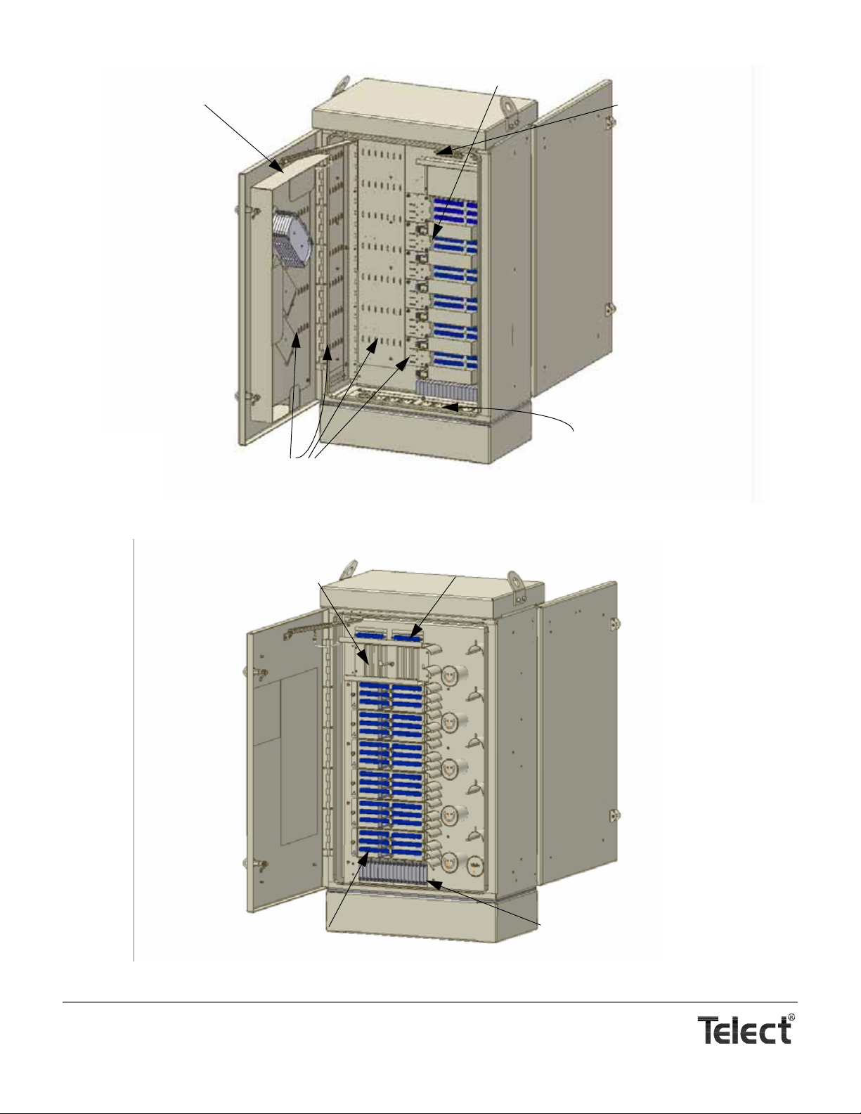
Distribution Adapters
Feeders to Front
Compartment
Lances for Anchoring Cable,
Feeder & Distribution
Cable Entrances
Subunits, and Loose Tu bing
Splice Box
Model MDC-SPLC
MDC-CB With In-Cabinet Splice Box (Rear Corner View)
Parking for Unassigned
Distribution
Feeders from Rear
Compartment to Splitters
Adapters for Assigned Distribution
Splitters in Splitter
Bulkhead
Front Corner View With Door Open
Telect, Inc. • USA +1.509.926.6000 • Mexico +1.52.33.3836.3700
Poland +1.48.713.239.100 • UK +1.44.1489.889500 • www.telect.com
Copyright © 2002 Telect, Inc., All Rights Reserved
Page 1-2
Page 7
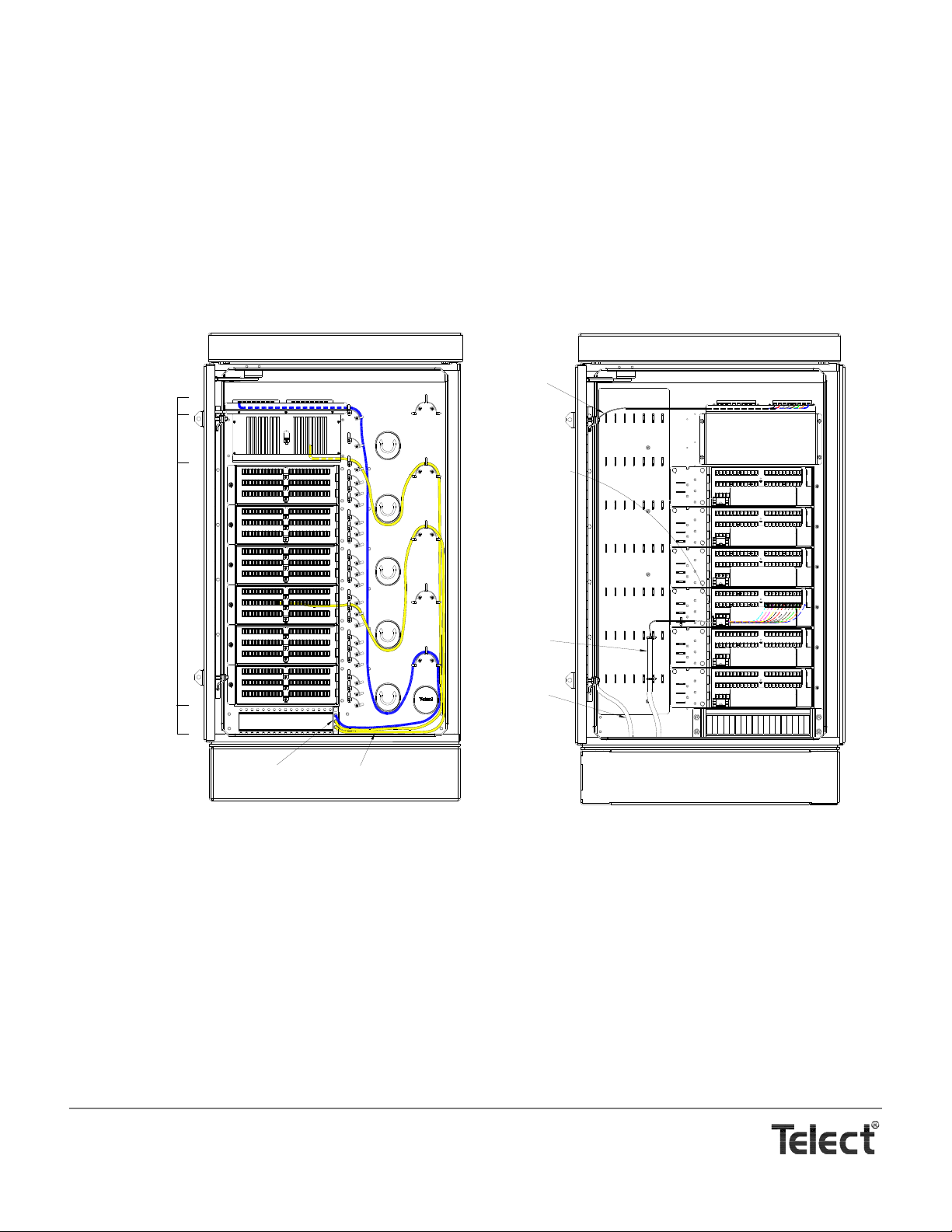
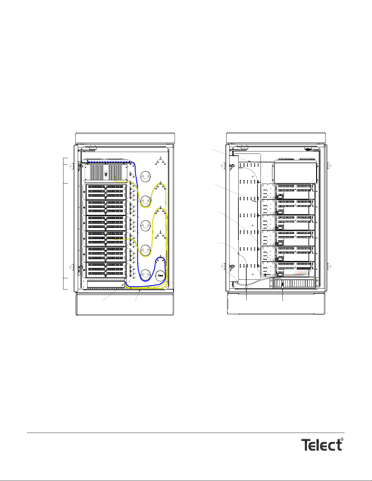
.MDC-CB WITHOUT REAR COMPARTMENT SPLICING
Front View With Door Open
*
Feeders
Assigned
Distribution
to Subscriber
Unassigned
Distribution
(Parking)
Splitter
Bulkhead
2 mm Jumpers
Splitter Module
OSP
Distribution
Cable
OSP Feeder
Cable
Subunit/Buffer
From Feeder
Cable Breakout
to Rear-Side
Feeder
Adapters
Fiber Furcated
From Multifiber
Buffer to
900-
µm Single
Fiber Loose
Tubing
Rear View With Door Open
*
* Splitter and Patch Modules are sold separately.
Cabling without in-cabinet splicing involves an aerial or below-ground splice box for splicing the distribution and feeder cables to
connectorized cabinet cabling.
• At the cabinet, the OSP distribution cable is clamped at the floor of the rear compartment and then routed along the cabinet’s compartment partition. The connectorized 250 µm strands break out here into subunits/buffers and then connected to
one of the six possible, 72-channel Patch Modules. Each patch module contains SC/APC adapters to interface the distribution fiber in the rear compartment to the cross connections in the front compartment.
• Feeder cable is anchored along the rear side wall where 900 µm fiber breaks out into subunits/buffers and routed to 16
SC/APC interface adapters near the top of the cabinet.
Each SC/APC adapter at the top of the cabinet serves to feed the fiber signal to a blue jumper in the front compartment, shown in the
preceding illustration. The blue jumper is routed down through the right portion of t he front compartment, then around a couple of
spools and an arc. The two spools at the bottom route the blue fiber to a Telect Splitter Module.
Up to 18, 1x4, 1x8, 1x16, or 1x32 Telect Splitter Modules can be installed in the splitter bulkhead at the bottom of the front compartment. Each splitter module consists of the splitter, one blue “input” jumper, and either 4, 8, 16, or 32 yellow “output” jumpers. All are
2 mm jumpers, 2.1 m in length.
Splitter module installation and all of the distribution changes occur in this front compartment:
• Unassigned jumpers are routed via spools and arcs to a parking station for later subscriber assignment.
• Assigned jumpers are routed via the spools and arcs to the front of the SC/APC adapters in the front of the patch modules
for cross connection to the distribution fiber connected to the rear of the patch modules.
Telect, Inc. • USA +1.509.926.6000 • Mexico +1.52.33.3836.3700
Poland +1.48.713.239.100 • UK +1.44.1489.889500 • www.telect.com
Copyright © 2002 Telect, Inc., All Rights Reserved
Page 1-3
Page 8
Each of the six possible patch modules (Model MDC-P72N) features 72 SC/APC cross-connect adapters for a total of 432 possible
4-in. Conduits
Two Cable Entrance Clamps
Are Included With Cabinet
To Accommodate
Two Feeder Cables*
Concrete Pad
One Cable Entrance Clamp
For a Distribution Cable*
Is Included With The
Patch Module
* Cable Entrance Clamps Accommodate
Cable Between 3/8 in. & 1-1/5 in.
In Dia. Additional clamps
Anchors & Conduit Are
Not Included With Cabinet.
Rear of Patch Module
Bar for Grounding
Single-Armored Cable
are available.
subscriber cross connections. Model MDC-P72N-F100D includes the Model MDC-P72N connected to 100 ft (~30.5 m) of Dri-Flex™
OSP cable containing 250 µm fiber furcated to 900 µm loose tubing with an SC/APC connector.
The following illustration shows a deployed cabinet along with a partially cabled rear compartment.
MDC-CB WITH REAR COMPARTMENT IN-CABINET SPLICING
The distribution and feeder OSP enter the cabinet at the floor of the rear compartment. The installer clamps the cable and breaks out
the fiber into 3-mm, radius-control (limited bend) loose tubing. The installer anchors feeder and distribution tubes along the cabinet’s
side wall and rear door.The tubes are guided to the top of the optional splice box located on the door.
The optional in-cabinet Telect Splice Box (Model MDC-SPLC) holds three pods of splice cassettes surrounded by a runway for the
loose tubing.
Telect, Inc. • USA +1.509.926.6000 • Mexico +1.52.33.3836.3700
Poland +1.48.713.239.100 • UK +1.44.1489.889500 • www.telect.com
Copyright © 2002 Telect, Inc., All Rights Reserved
Page 1-4
Page 9
Each cassette normally accommodates 24 splices. If all feeder and distribution fiber requires splicing, a total of 18 cassettes are
Feeders
Assigned
Distribution
to Subscriber
Unassigned
Distribution
(Parking)
Splitter
Bulkhead
2 mm Jumpers
Splitter Module
Front View With Door Open
*
Rear View With Door Open
*
Loose Tubing
From Splice
Box to
Rear-Side
Feeder
Adapters
Loose Tubing
From Splice Box
to Rear-Side
Distribution
Adapters
OSP Feeder
Cable From CO
OSP Distribution
Cable
Loose Tubing
From Feeder
Cable to Splice
Box
Loose Tubing
From Distribution
Cable to Splice
Box
Fiber Furcated
From 3-mm
Multifiber Loose
Tubing to
900-
µm Single
Fiber Loose
Tubing
* Splitter Modules, Patch Modules, Splice Box, Splice Cassettes, Fan-Out Blocks, and Radius-Control Loose Tubing are Sold Separately.
needed to accommodate all 432 subscribers. For the distribution splices, each pod would hold 6 splice cassettes plus one additional
cassette on one of the pods for up to 16 feeder splices.
Feeder and distribution strands are spliced to connectorized fiber protected by 3-mm, radius control loose tubing. All tubing from the
cassettes to the feeder interface and patch modules cross the door hinge near the top of the cabinet. The tubing is anchored along
the compartment partition and guided to SC/APC feeder or distribution adapters:
• The feeder interface near the top, rear-side of the cabinet contains 16 adapters to pass feeder signals to the front compartment splitters.
• The distribution adapters are located on 72-port modules (Models MDC-P72N). Fa n-out blocks on the Patch Modules are
used to accommodate the transition from 3-mm, multi-fiber loose tubing to 900 µm transparent tubes, one for each of the
72 fibers. A total of 6 Patch Modules accommodate the 432 possible subscribers. The SC/APC adapters pass signals to the
front compartment for assignment patching.
FRONT COMPARTMENT CROSS CONNECTIONS
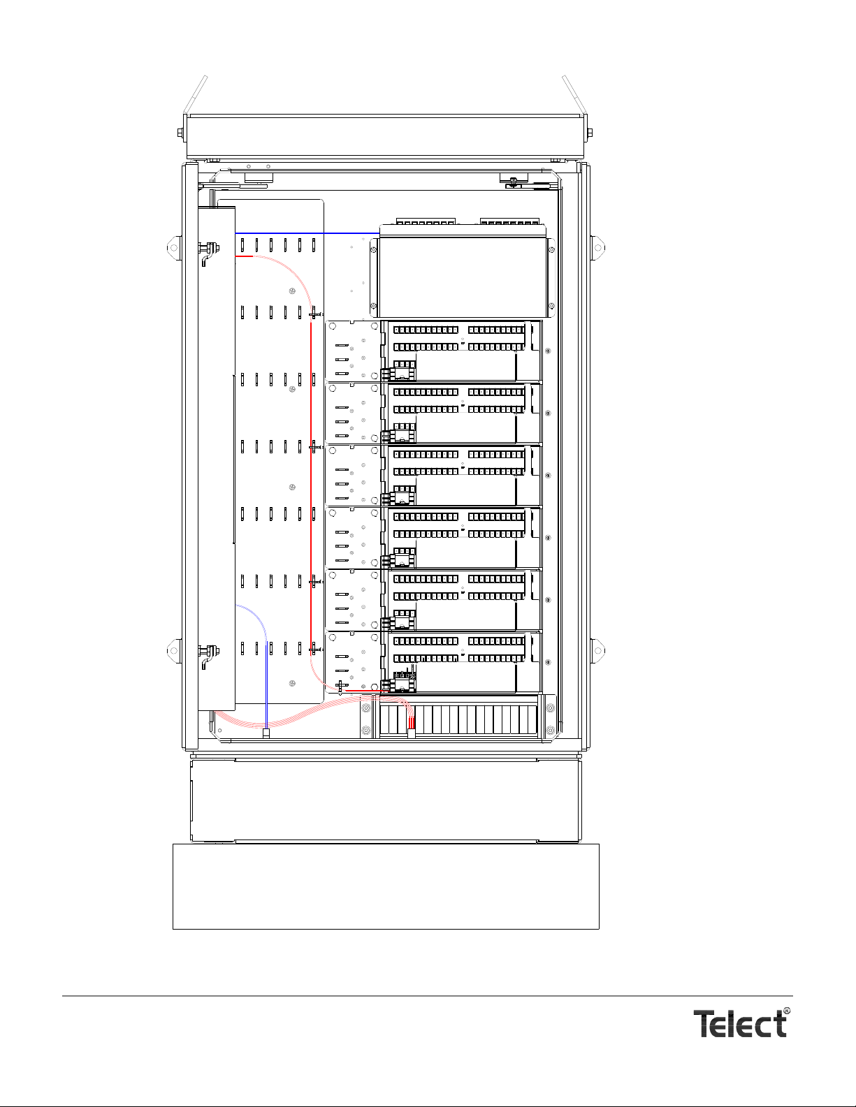
Front compartment feeder and cross-connect cabling is the same for cabinets with or without in-cabinet splicing.
Each SC/APC adapter at the top of the cabinet serves to feed the fiber signal to a blue jumper in the front compartment. The blue
jumper is routed down through the right portion of the front compartment, then around a couple of spools and an arc. The two spools
at the bottom route the blue fiber to a Telect Splitter Module.
Telect, Inc. • USA +1.509.926.6000 • Mexico +1.52.33.3836.3700
Poland +1.48.713.239.100 • UK +1.44.1489.889500 • www.telect.com
Copyright © 2002 Telect, Inc., All Rights Reserved
Page 1-5
Page 10

Up to 18, 1x4, 1x8, 1x16, or 1x32 Telect Splitter Modules can be installed in the splitter bulkhead at the bottom of the front compartment. Each splitter module consists of the splitter, one blue “input” jumper, and either 4, 8, 16, or 32 yellow “output” jumpers. All are
2 mm jumpers, 2.1 m in length.
Splitter module installation and all of the distribution changes (patching) occur in this front compartment:
• Unassigned jumpers are routed via spools and arcs to a parking station for later subscriber assignment.
• Assigned jumpers are routed via the spools and arcs to the front of the SC/APC adapters in the front of the patch modules
for cross connection to the distribution fiber connected to the rear of the patch modules.
FEATURES
• Simple cabling scheme. Separate compartments for OSP cable (feeder & distribution at the rear) with splitter growth an d
cross-connections at the front
• Patch module bulkhead swings out into front compartment for convenient adapter and connector inspection and maintenance
• 30 mm (min.) bend radius control throughout cabinet & accessories
• Highest splitter density — up to 32 splits per splitter module
• Expandable. Easily add splitter modules as distribution grows
• Popular bulkhead-style modular distribution (up to 6, 72-channel patch modules)
• Bulkhead-style splitter bank for up to 18 Splitter Modules containing 1x4, 1x8, 1x16, or 1x32, premium PLC splitters
• Laser eye protection throughout. All adapters and connectors include dust caps
• Front & rear padlockable doors with wind strays (padlocks not included). Routing guide and designation chart located conveniently on inside of front door.
• Includes grounding bar for armored cable.
BENEFITS
• Low cost — High Fiber Density — Versatility
• Better access — full front and rear doors open wide for simple access and installation
• Simple Site Prep
• Easy Installation. Ideal for both local and remote sites
• Designed for compliance: NEMA 4, GR-771, GR-487
• Designed & Built for Growth
• Simple, straight-forward cable management, access, circuit identification.
SPECIFICATIONS & CAPACITIES
• Dimensions (Overall WxHxD): 28 x 54 x 18 in (710 x 1375 x 460 mm). See the following for detailed dimensions.
• Weight (without modules, accessories, or cabling): ~125 lb (~60 kg).
• Feeder & Distribution Cable Entrance Positions/Capacity: 16
• Cable Diameter:
Telect, Inc. • USA +1.509.926.6000 • Mexico +1.52.33.3836.3700
Poland +1.48.713.239.100 • UK +1.44.1489.889500 • www.telect.com
Copyright © 2002 Telect, Inc., All Rights Reserved
3
/8 in. (9.6 mm) to 11/5 in. (30 mm), max.
Page 1-6
Page 11
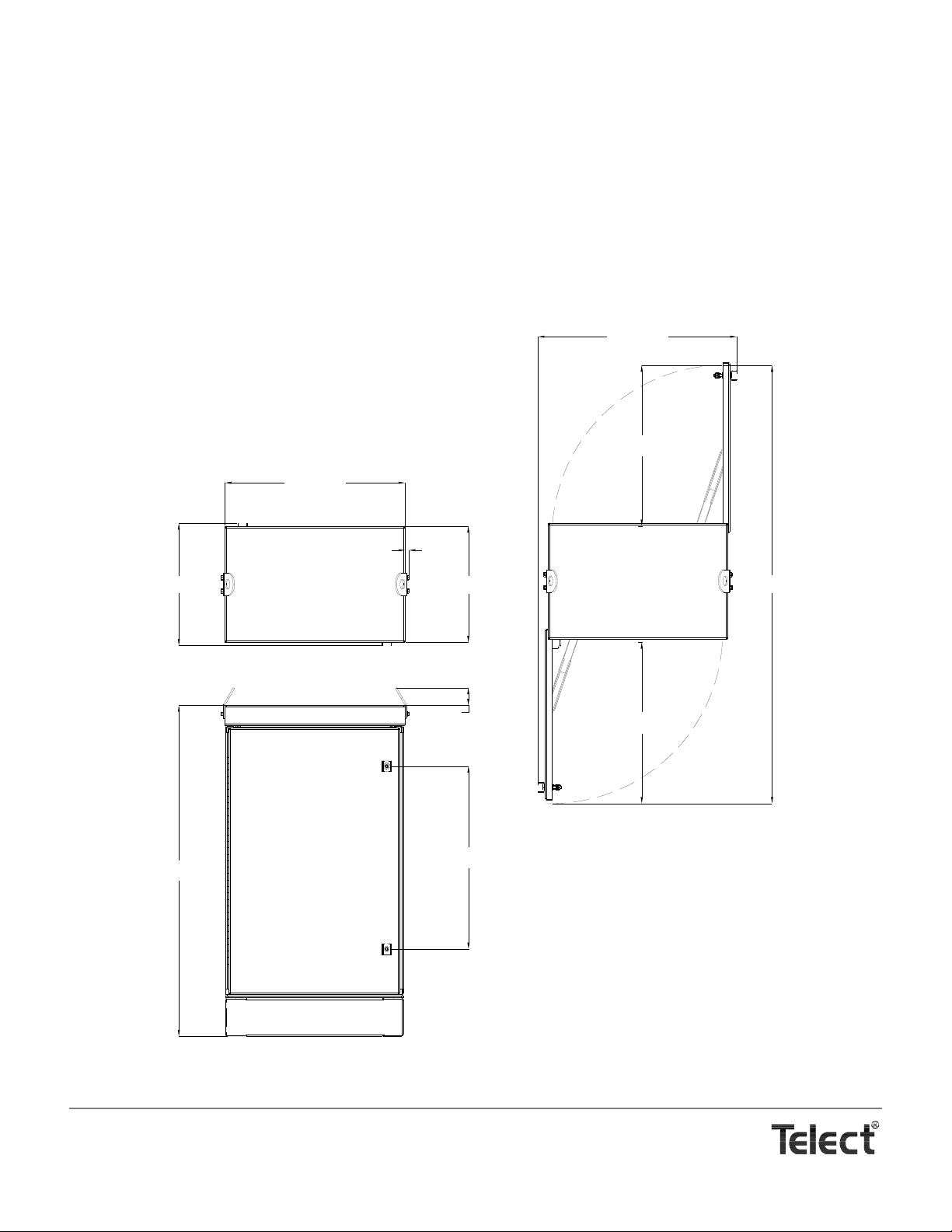
• Fiber Signals: 16 feeder signals, max.; 432 distribution signals, max.
30.74 [780.9]
67.79 [1721.9]
27.86 [707.7]
18.00 [457.2]
18.94 [481.0]
2.72 [69.1]
51.24 [1301.4]
24.87 [631.7]
24.92 [633.0]
28.31 [719.0]
0.64 [16.2]
• Adapters: SC/APC at cabinet end of fibers
• Cross-Connect Bulkhead Positions: 6, max. Each bulkhead accommodates 72 X-connects (6 x 72 = 432)
• Splitter Module Positions: 18, max. Each accommodates a 1x4, 1x8, 1x16 or 1x32 Telect Splitter Modules with front
access installation and cabling. “Inputs” and “outputs” are 2-mm jumpers, 2.1 m long with SC/APC connectors
• Parking Positions: 72, max., to accommodate unassigned split-
ter “outputs”
• Cabinet Material: 0.125 in, 5052 Aluminum
• Cabinet Finish: Powder-coat almond
Telect, Inc. • USA +1.509.926.6000 • Mexico +1.52.33.3836.3700
Poland +1.48.713.239.100 • UK +1.44.1489.889500 • www.telect.com
Copyright © 2002 Telect, Inc., All Rights Reserved
Page 1-7
Page 12

Page 1- 8
Page 13
2. Cabinet Installation
WARNING
!
ALERT
!
ALERT
!
INSTALLATION CONSIDERATIONS
WARNING! Fiber ca bles transmit invi sible infrared light . To avoid eye damage or b lindness, never loo k directly
into fibers or connectors.
WARNUNG! Faserkabel übertragen unsichtbares Infrarotlicht. Um eine Schädigung der Augen oder Blindheit
zu vermeiden, schauen Sie nicht direkt in die Fasern oder Stecker.
ADVERTENCIA ! Los cables de fibra transmiten luz láser o infrarroja invisible. Para evitar lesiones oculares o
ceguera, nunca mire directamente a las fibras o conectores.
AVERTISSMENT ! Les câbles à fibres transmettent un rayon laser ou une lumière infrarouge invisible. Pour
éviter toute lésion occulaire ou cécité, ne regardez jamais directement dans les fibres ou dans les
connecteurs.
ALERT! This product must be installed and maintained only by qualified technicians.
ALERT! These instructions presume you have verified that the Telect equipment being inst alled is compatible
with the rest of the system, including power , ground, cir cuit protection, signal char acteristics, equipment from
other vendors, and local codes or ordinances.
PRE-INSTALLATION
Location & Layout —
Use the floor template (isolation pad), or the following illustration, to lay out and construct a re-enforced concrete pad, grating, or
other suitable, stable platform to accommodate the cabinet, anchorage, and cabling. Concrete pads must be at least 6 in. (~150
mm) thick.
Telect does not include an anchor kit or a vault-to-cabinet adapter with the cabinet. Order Telect’s seismic anchor kit (Model
MDC-CBAK) for either indoor or outdoor deployment on concrete. (See “Standard Accessories” Page 7-1.) Model MDC-CBAK
is an expansion-style anchor requiring drilling into the pad; also acceptable are embed L-shaped anchors with ½ in. (M12)
threads, available at appropriate hardware or specialty stores.
Telect, Inc. • USA +1.509.926.6000 • Mexico +1.52.33.3836.3700
Poland +1.48.713.239.100 • UK +1.44.1489.889500 • www.telect.com
Copyright © 2002 Telect, Inc., All Rights Reserved • Telect Publication 131220 A0
Page 14
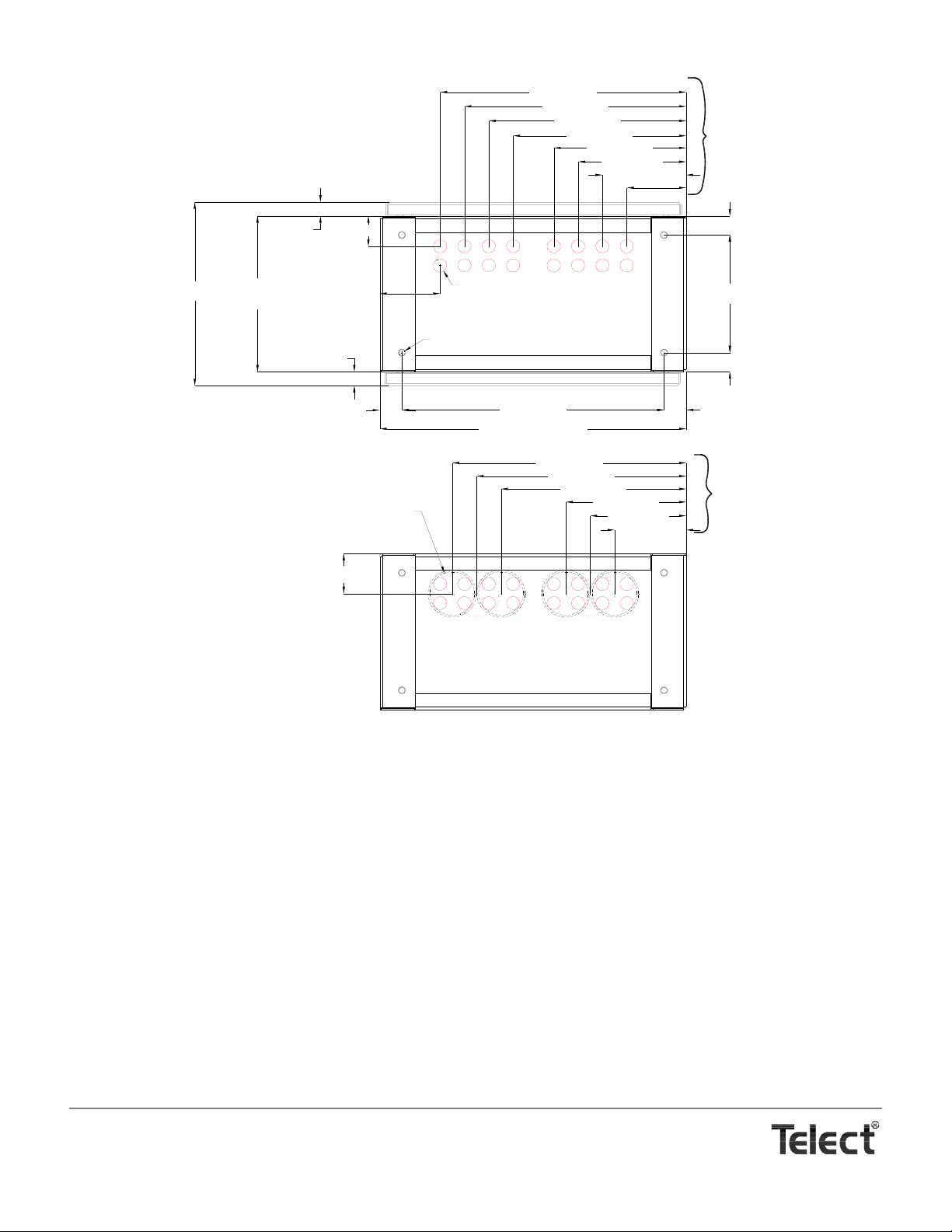
16.85 [428.0]
1.28 [32.5]
1.28 [32.4]
14.29 [363.0]
Footprint
Ø0.50 [Ø12.7]
Anchor Holes
10.79 [274.0]
23.52 [597.4]
1.99 [50.6]
1.99 [50.6]
1.75 [44.5]
1.75 [44.5]
27.50 [698.5] Footprint
Ø4.00 [Ø101.6] Stub-Up Conduit
6.43 [163.2]
8.61 [218.7]
10.80 [274.2]
16.62 [422.2]
18.81 [477.7]
20.99 [533.2]
3.66 [93.0]
Ø1.20 [Ø30.5]
Max. Cable Dia.
2.79 [70.8]
5.41 [137.5]
5.33 [135.5]
7.52 [191.0]
9.70 [246.5]
11.89 [302.0]
15.53 [394.5]
17.72 [450.0]
19.90 [505.5]
22.09 [561.0]
Cable Clamp
Positions (16)
Conduit Positions
Vs Cable Clamp
Positions
FRONT
REAR
FRONT
REAR
NOTE: Dimensions are in in. (mm)
Please note the following recommendations:
• Telect recommends that the cabinet be mounted with either the 6-in.-high base or optional 12-in.-high base (Models MDCR12) or a suitable vault, along with the isolation pad included with the cabinet. (See “Standard Accessories” Page 7-1.) If
the cabinet is mounted to a concrete pad without a pedestal or vault, the stub-up conduit for the cables must be positioned
accurately and must be either absolutely flush with or countersunk below the top of the pad.
• For a cabinet with a Telect base, the stub-up conduit should not rise above a concrete pad more than about 3 in. (~75 mm)
for a 6-in.-high base and about 6 in. (~150 mm) for a 12-in .-high base. See the following illustration.
• Telect recommends running cables in 4-in. stub-up conduit. Normally, two 4-in. conduits are necessary: one for the feeder
cable(s) and at least one for the distribution cable(s), as shown in the illustration that follows. Prefer to run feeder cable as
close as possible to the grounding bar — regardless if feeder is armored or unarmored.
• Don’t forget to make room for growth. Add additional 4-in. conduit and cap off the end(s) at the edge of or beyond the pad.
• Telect recommends anchors at all four corners. Upper end of anchor bolts must extend between 1¼ in. and 1½ in. above
top of pad, grating, or platform.
• For outdoor deployment, Telect recommends that, in addition to the isolation pad provided with the cabinet, that the customer plan for and provide a suitable water-tight gasket between the bottom of the cabinet and the pad. Use the preceding
illustration to mark and cut a rectangular hole for cable entrance.
Telect, Inc. • USA +1.509.926.6000 • Mexico +1.52.33.3836.3700
Poland +1.48.713.239.100 • UK +1.44.1489.889500 • www.telect.com
Copyright © 2002 Telect, Inc., All Rights Reserved
Page 2-2
Page 15
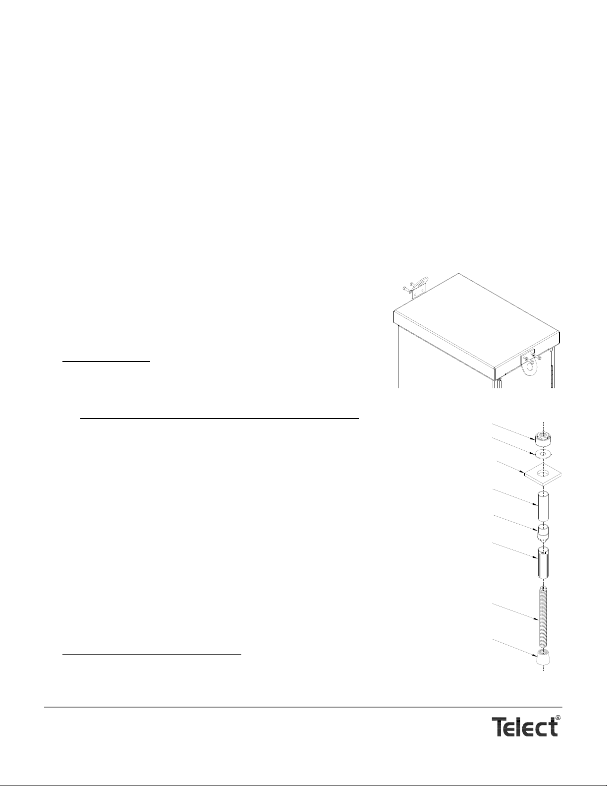
Tools & Equipment —
Lifting Ring Orientation
(As Shipped)
Re-Orient Rings
to Lift Cabinet
Cone
Threaded Rod
Expansion Sleeve
Metal Sleeve
Round Washer
Torque Nuts With Red Plastic Collar
Plastic Guide
Square Washer
Model MDC-CBAK Anchor Kit
No special tools required for installation.
INSPECTION
Telect is not liable for shipping damage.
Keep the container until you have checked equipment operation. If you experience any kind of problem, call Telect’s Customer Ser-
vice Department. Use the original, undamaged container if you are instructed to return a panel to Telect.
If a shipping container is damaged, keep it for the carrier’s inspection. Notify the carrier and call Telect’s Customer Service Depart-
ment at 1-800-551-4567 or 1-509-926-6000
INSTALLATION PROCEDURE
Please read these instructions carefully before beginning installation. If you need assistance call Technical Support at 888-821-4856
(domestic calls), or 509-921-6161 (Option 2), or eMAIL us at [email protected]
1. Inspect equipment after unpacking and compare it to the packing list.
Immediately report any shipping damage, defects, or missing parts to
Telect at 1-800-551-4567. Keep all documentation that comes with your
shipment.
2. Remove lifting rings at top of cabinet and then resecure as shown on the
right.
3. Before moving cabinet
is ready: namely,
• If installation includes a vault, make sure vault-to-cabinet adapter is
in place.
, make sure the pad, grating, vault, or other support
• If using Telect’s seismic anchor kit (Model MDC-CBAK), install anchors
lows:
a. Drill an 18 mm (
25
/32-in.) diameter hole, 100 to 115 mm (4¼ to 4½ in.) deep,
at each of the four anchor locations.
b. Clean out holes using a shop vacuum, compressed air, or blow-out bulb.
Clean away debris.
c. Place round washer on rod and then thread torque nut onto the rod. The
washer should touch the top of the metal sleeve.
d. Insert anchor assembly (without the square washer) into hole. Tap anchor
rod down with a hammer until washer touches the concrete.
e. Pre-torque anchoring nuts to approximately 30 ft-lb (~40 N•m) using a ¾ in.
(19 mm) socket or box wrench.
Do not overtighten. Over-tightening will cause the torque nut to prematurely
shear off from the plastic-encased holding nut.
f. Remove torque nut and washer, leaving anchor and stud in place.
g. For exterior installation on a concrete pad, place a water-tight gasket with
cutouts for conduit and anchors on top of pre-installed pad.
4. If installation includes a base (recommended), proceed as follows:
a. Place base over anchor studs, as shown in the following illustration.
, as fol-
Telect, Inc. • USA +1.509.926.6000 • Mexico +1.52.33.3836.3700
Poland +1.48.713.239.100 • UK +1.44.1489.889500 • www.telect.com
Copyright © 2002 Telect, Inc., All Rights Reserved
Page 2-3
Page 16
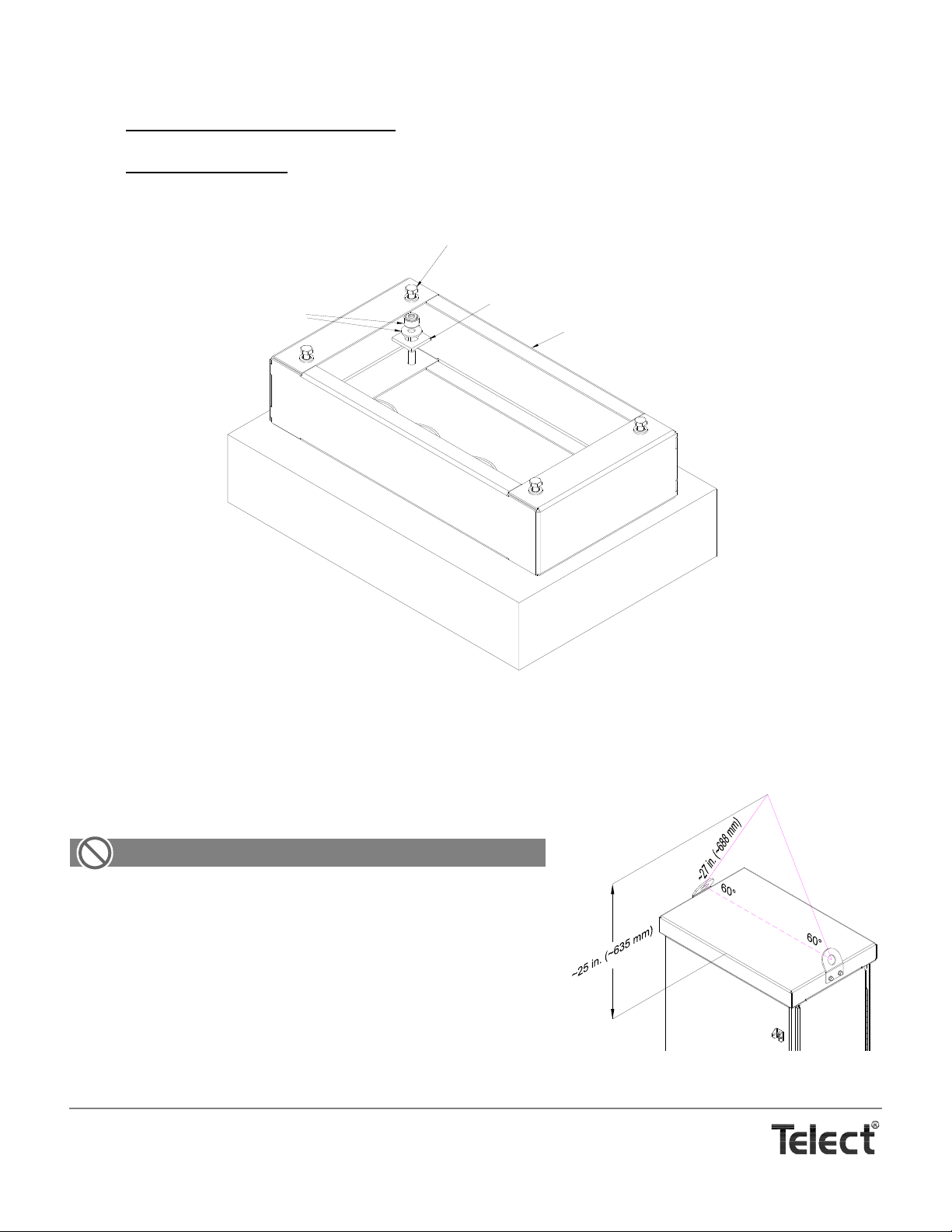
b. The front versus rear of the base are dimensionally alike and interchangeable. The top versus bottom are not.
ALERT
Either Square Washer From
Anchor Kit or a 1/4-in. Stack of
1/2-in. Fender Washers
Remove 1/2 in. Bolts & Washer Before Se tting Cabinet on Base
Base
Washer & Breakaway Nut
From Anchor Kit
Installing a Base Using Telect Model MDC-CBAK Anchor Kit
c. Place square washer from the anchor kit over the studs.
d. If using a regular L-shaped concrete anchor
in. low-carbon steel studs and fasteners or 83 ft-lb for
, use a suitable nut and tighten all four corner anchors evenly to 38 ft-lb for ½-
3
/8-in. hardware.
If using a Telect anchor kit, tighte n br ea kaway torque nut until it shears off plastic-encased holding nut. At shear point, the
holding nut will be properly torqued to 60 ft-lb.
e. Remove and save four bolts and washers at top of base.
5. Use the illustration on the right as a guide in designing a two-point lift
for moving and placing cabinet over anchors.
ALERT! DO NOT STAND BENEATH THE CABINET DURING
LIFTING.
6. After moving cabinet into place over anchors, use the Allen-head-style
key to open the doors.
7. Fasten cabinet to base or vault adapter, as shown in the following illustration.
If fastening to a base, use the hardware removed in Step 4d.
8. Torque ½ in., low-carbon steel nuts/bolts to 38 ft-lb.
Telect, Inc. • USA +1.509.926.6000 • Mexico +1.52.33.3836.3700
Poland +1.48.713.239.100 • UK +1.44.1489.889500 • www.telect.com
Copyright © 2002 Telect, Inc., All Rights Reserved
Page 2-4
Page 17
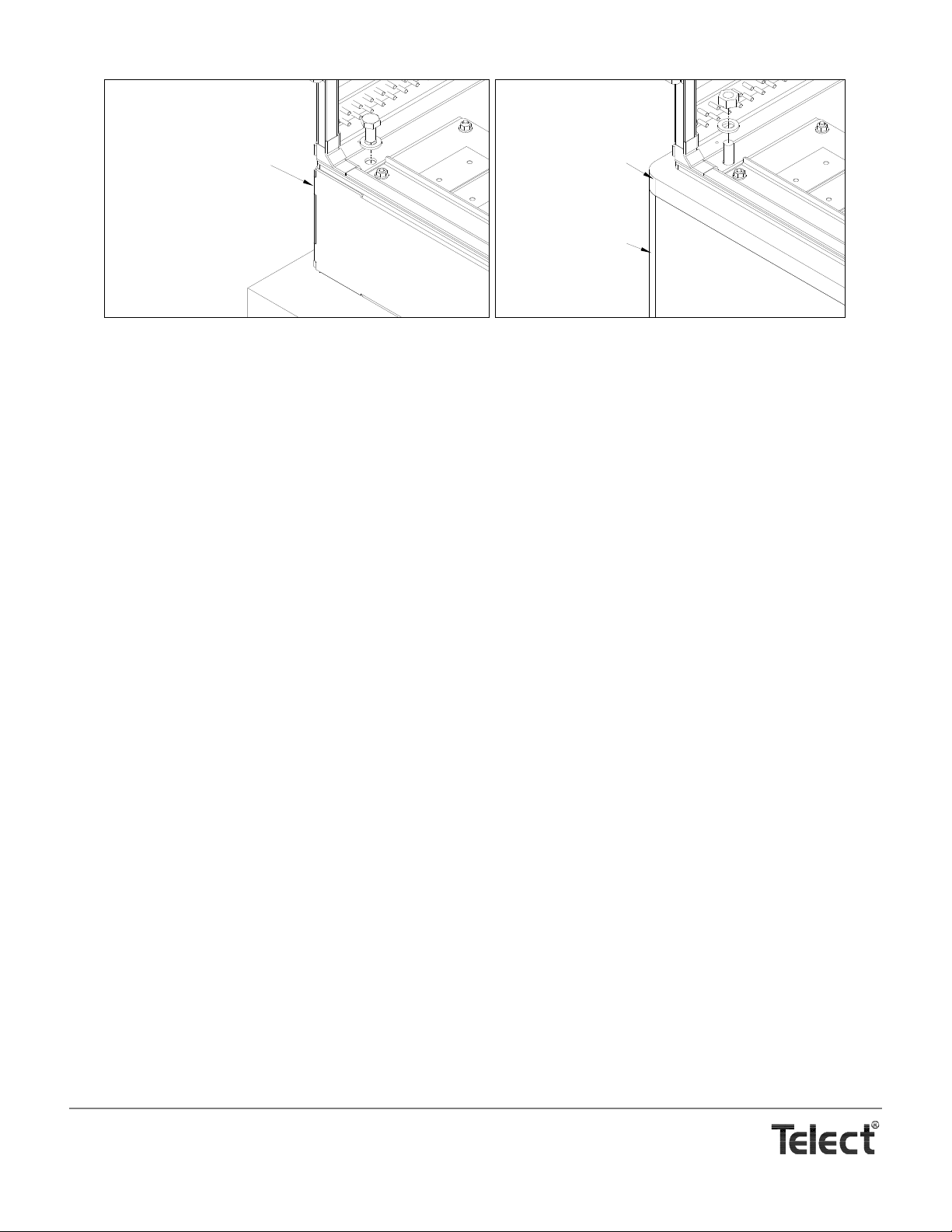
Base
Adapter
Vault
Telect, Inc. • USA +1.509.926.6000 • Mexico +1.52.33.3836.3700
Poland +1.48.713.239.100 • UK +1.44.1489.889500 • www.telect.com
Copyright © 2002 Telect, Inc., All Rights Reserved
Page 2-5
Page 18

Telect, Inc. • USA +1.509.926.6000 • Mexico +1.52.33.3836.3700
Poland +1.48.713.239.100 • UK +1.44.1489.889500 • www.telect.com
Copyright © 2002 Telect, Inc., All Rights Reserved
Page 2-6
Page 19
3. Cabling Without In-Cabinet Splicing
WARNING
!
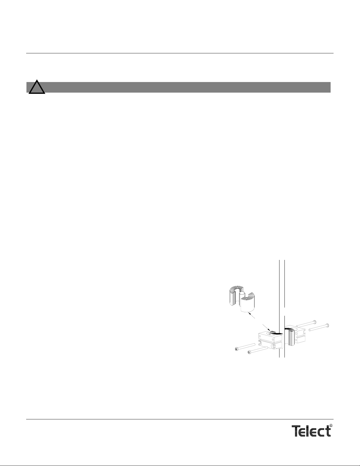
Bushing Leaves
OSP Cable
Leaves are provided in an onion
skin roll to accommodate
multifiber cabling from .375 in. to
1.25 in. (9.5 mm to 32 mm) in dia
WARNING! Fiber c ables transmit invis ible infrar ed lig ht. To avoid eye damag e or blindness , ne ver loo k direc tly into fibers or connectors.
WARNUNG! F aserkabel übe rtragen unsichtba res Infrarotlicht . Um eine Schädigung der Augen oder Blindheit
zu vermeiden, schauen Sie nicht direkt in die Fasern oder Stecker.
ADVERTENCIA ! Los cables de fibra transmiten luz láser o infrarroja in visible. Para evit ar lesiones oculares o
ceguera, nunca mire directamente a las fibras o conectores.
AVERTISSMENT ! Les câbles à fibres transmettent un rayon laser ou une lumière infrarouge invisible. Pour
éviter toute lésion occulaire ou cécité, ne regardez jamais directement dans les fibres ou dans les
connecteurs.
Fiber installation without in-cabinet splicing involves installing connectorized OSP feeder cables to the floor of the cabinet’s rear compartment and then terminating those connectors at compartment interface adapters near the top of the cabinet. The connectorized distribution cabling is pre-terminated to the patch module assemblies at the factory. These optional patch module assemblies are secured to the cabinet partition. The distribution cables, like the feeder cables, are
secured to the bottom floor of the rear compartment.
After installing all feeder and distribution cables at the cabinet end, the opposite ends are then spliced to OSP cables located in a splice enclosure.
FEEDER CABLE INSTALLATION
The cabinet accommodates up to 16 strands of connectorized OSP feeder
cable. Telect supplies two cable clamps that accommodate cables between
3
/8 in. (9.6 mm) and 11/5 in. (30.5 mm) in diameter. Each clamp, shown on
the right, uses several layers of gasket or bushing leaves to hold the cable
fast between the two halves of the clamp.
OSP cable can be dry or wet, armored or unarmored. T o connect to adapters
in the cabinet the cable needs SC/APC connectors.
To install a feeder cable, proceed as follows:
1. Open rear door.
2. Remove cable entrance dock at bottom of cabinet by removing six sets
of nuts and washers shown in the following illustrations.
The cable entrance dock contains eight slots with slide-out cover plates.
Each slots can accommodate two cable clamps for either feeder or distribution cable.
3. Slide out cover plate over feeder stub up.
If all feeder cable enters through the stub up closest to the feeder tie-down wall, choose the slot nearest the tie-down wall. If a
second feeder cable is being installed, prefer to locate both in the same slot.
Telect, Inc. • USA +1.509.926.6000 • Mexico +1.52.33.3836.3700
Poland +1.48.713.239.100 • UK +1.44.1489.889500 • www.telect.com
Copyright © 2002 Telect, Inc., All Rights Reserved • Telect Publication 131220 A0
Page 20
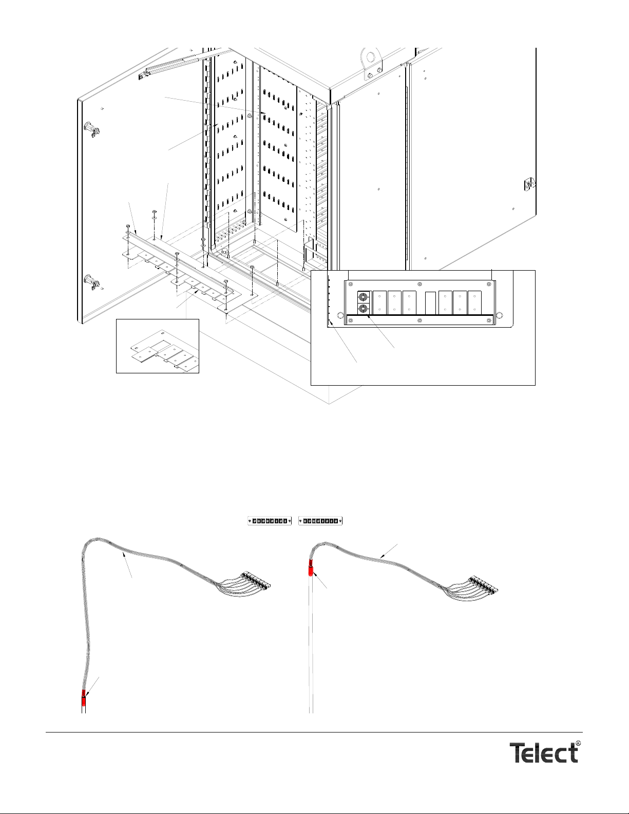
4. Use the next illustration to calculate the length of cable(s) required between the splice box (v ault or aerial enclosure) and the
Cable Entrance Dock
Cover Plates
Chock Bar
Preferred Locations of Feeder Cable Clamps
Tie-Down Lance on Feeder Tie-Down Wall
Top View of Cabinet's Rear Floor
Feeder Tie-Down Wall
Distribution Tie-Down Wall
OSP Feeder Cable From Splice Enclosure (Dressed Out)
16
9
8
Breakout from Cable to
Subunits/Buffers Near Bottom
of Rear Compartment
Breakout from Cable to
Subunits/Buffers Near Top of
Rear Compartment
Subunit/Buffer Between
Breakout and Connector:
~40 in. for Connector 16
to ~50 in. for Connector 1
1
Subunit/Buffer Between
Breakout and Connector:
~15 in. for Connector 16
to ~25 in. for Connector 1
Feeder Adapters
(Rear Compartment View)
feeder adapters near the top of the cabinet’s rear compartment. Use heat-shrink tubing to secure the loose tubing at the end of
the cable(s).
The illustration shows approximate lengths of exposed subunits/buffers to accommodate the 900 µm fiber between the breakout
and the SC/APC connectors. Any breakout length between 15 in. and 50 in. will fit: a short breakout length would place the
breakout near the top of the feeder tie-down wall; conversely longer lengths would be tied down closer to the cable entrance.
Telect, Inc. • USA +1.509.926.6000 • Mexico +1.52.33.3836.3700
Poland +1.48.713.239.100 • UK +1.44.1489.889500 • www.telect.com
Copyright © 2002 Telect, Inc., All Rights Reserved
Page 3-2
Page 21
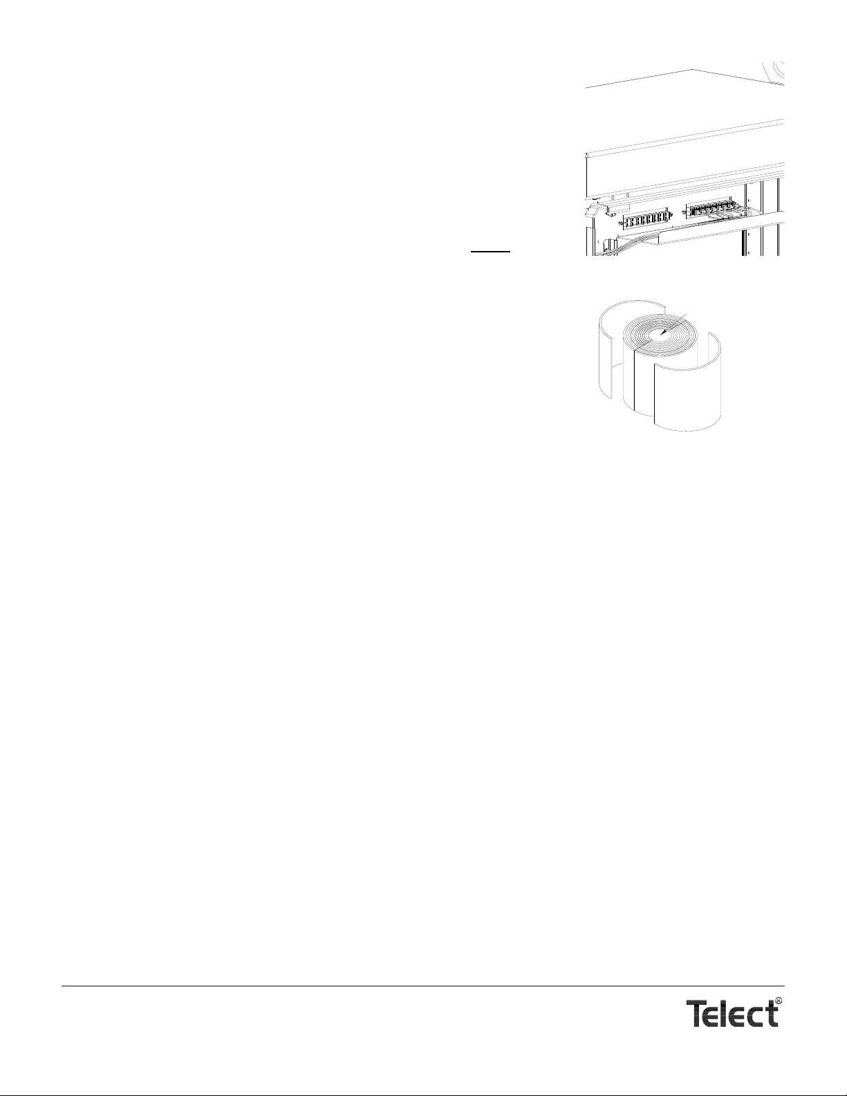
5. Feed opposite end of feeder cable(s) through stub-up conduit to splice vault or aerial en-
Bushing Leaf
Solid Core (Discard)
closure. Before splicing, use cable ties “temporarily“ to hold the cable end(s) in the cabinet to convenient lance(s) along the feeder tie-down wall. Tie it down temporarily so that
the SC/APC connectors will reach the feeder adapters at the top of the rear compartment.
6. Wait until all feeder cable is connected and secured in the cabinet before external splicing.
7. Connect SC/APC connectors on all feeder fibers to feeder adapters.
8. Measure diameter of cable(s) and remove and discard that much from the interior of the
cable clamp’s leaf bundle equal to the diameter of the cable(s). The remaining leaves will
be used between the clamp halves and the cable.
9. Nearby the cable entrance, where the cable entrance dock had been, loosely
secure the
left bundle(s) and clamp halves to the cable(s), as shown in the illustration at the start of
this procedure.
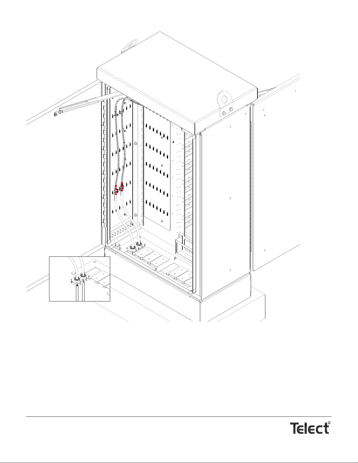
10. Place cable entrance dock at bottom of cabinet and slip on cable clamps, as shown in the
illustration on the following page.
If you have only one feeder cable to install, you must use the other cable clamp to fill out
the slot.
11. Hold down or temporarily fasten dock to cabinet, and then arrange feeder cable(s) and
tubing along the feeder tie-down wall. Use cable ties generously to fasten cable and tubing to the wall.
Don’t use cable ties closer than ~1 ft (~300 mm) from the floor until all feeder and distribution cables are installed. You’ll need some wiggle room for removing/re-installing the cable entrance dock.
12. Remove the entrance dock again and securely fasten the cable clamps to the cable.
You will fasten the entrance dock to the cabinet after the distribution cable is installed in the next subsection.
A cabinet with feeder cable installed is shown on the following page.
13. Splice the other end of the feeder cable.
Telect, Inc. • USA +1.509.926.6000 • Mexico +1.52.33.3836.3700
Poland +1.48.713.239.100 • UK +1.44.1489.889500 • www.telect.com
Copyright © 2002 Telect, Inc., All Rights Reserved
Page 3-3
Page 22
PATCH MODULE & DISTRIBUTION CABLE INSTALLATION
Feeder Cable (Installed)
Patch Modules come with a 72-strand distribution cable installed at the factory, as shown in the following illustration. The cable is a
dry, unarmored cable containing 6 subunits each with 12, 250 µm fibers.
Telect, Inc. • USA +1.509.926.6000 • Mexico +1.52.33.3836.3700
Poland +1.48.713.239.100 • UK +1.44.1489.889500 • www.telect.com
Copyright © 2002 Telect, Inc., All Rights Reserved
Page 3-4
Page 23
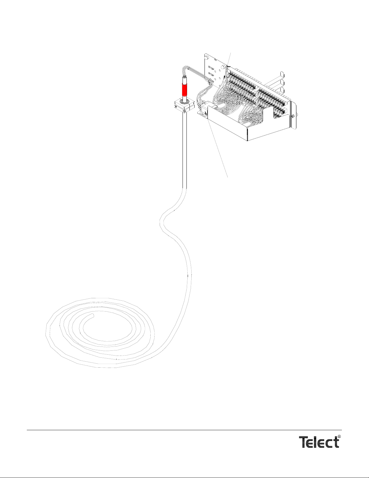
72-Strand OSP Cable
Patch Module
Front
Rear
Cable Clamp
Heat-Shrink Tube
Subunits
(6, with 12, 250 µm fibers ea)
Fan-Out Blocks
(6, with transition to 12, 900 µm transparent tubes)
Transparent Tubes, Each Containing a
250 µm Fiber With an SC/APC Connector
Patch Module With Distribution Cable
Telect offers a standard length of cable to fit most applications: 100 ft (30.48 m), measured from a fan-out block attached to the
Patch Module to the stub end. (Custom lengths available on request.) Telect breaks out short lengths of subunits for the shortest
probable distance from the cable clamp to the Patch Module. The subunit breakout can be increased on site. Telect includes the cable clamp for securing the cable to the bottom of the cabinet and a short length of heat-shrink tubing for covering the breakout.
Telect, Inc. • USA +1.509.926.6000 • Mexico +1.52.33.3836.3700
Poland +1.48.713.239.100 • UK +1.44.1489.889500 • www.telect.com
Copyright © 2002 Telect, Inc., All Rights Reserved
Page 3-5
Page 24

The cable clamp, shown on Page 3-1, is the same type used to secure distribution cable. One cable clamps is provided. An additional cable clamp may be required to fill out the two-position entrance slot. (See “Standard Accessories” on Page 7-1.)
The fan-out block allows transition from the 250 µm fiber in subunits to individual connectorized fiber strands in 900 µm transparent
tubes. Telect terminates the connector at adapter ports at the rear of the patch module.
To install a Patch Module with distribution cable, proceed as follows:
1. Open rear door.
2. Remove cable entrance dock at bottom of the cabinet, shown on Page 3-2.
3. Slide-out cover plate over distribution stub up(s).
Patch Modules will be installed from the top position (Patch Module 1) to the bottom (Patch Module 6). Unless otherwise direct-
ed by operating company guidelines, prefer to start with the first distribution stub-up farthest from the patch module rack.
Determine the length of the subunit breakout between the fan-out blocks on the edge of the patch module and the sheathed ca-
ble. The end of the sheathed cable will be either clamped and tied down on the distribution tie-down wall or
at the cable clamp
on the cable entrance dock.
NOTE
Telect only breaks out about 7 in. (~175 mm) of subunit. Th is would be for the shortest b reakout from a cable clamp near the
center of the cable entrance dock to Patch Module 6. The longest bre akout would be about 64 in (~160 0 mm) betwe en a cable
clamp near the left wall (viewed from the front of the cabinet) to Patch Module 1.
All cables entering the cabinet directly below the patch module rack need to be broken ou t at the cabl e cl amp. The cable is not
flexible enough to manipulate it below the rack and around to the distri bution tie-down wa ll. Conversely, all cables entering the
cabinet directly below the distribution tie down wall should be extend ed up the tie-dow n wall and tied down just below a co nvenient breakout point. (Refer to the illustration on Page 1-4.)
4. Breakout subunits, heat shrink breakout, and then feed the opposite end of the cable into the distribution stub-up condu it.
5. Move the cable clamp down to approximately where the cable will enter the bottom of the cabinet.
NOTE
Before connecting, splicing, storing, or parking distribution pigtails at the home, office, or node, install the Patch Module in the
cabinet, as detailed in the following procedure. Refer to the following illustration.
6. If necessary, provide temporary strain relief while handling and installing Patch Module by, for example, loosely tying down the
cable at a convenient lance along a tie-down wall.
7. Swing out hinged bulkhead from patch module’s anchor plate so that bulkhead fits through rack into front compartment. Then,
secure anchor plate to partition wall using three acorn nuts provided.
8. Secure cable and subunit to distribution cable tie-down wall. Use plenty of cable ties.
Don’t use cable ties closer than about 1 ft (~300 mm) from the floor of the cabinet until all feeder and distribution cables are in-
stalled. You’ll need some wiggle room for re-installing the cable entrance dock.
9. At bottom of cabinet, adjust position of cable clamp in relationship to the cable entrance dock. Don’t secure the entrance dock
until all scheduled distribution cables and Patch Modules are installed.
Telect, Inc. • USA +1.509.926.6000 • Mexico +1.52.33.3836.3700
Poland +1.48.713.239.100 • UK +1.44.1489.889500 • www.telect.com
Copyright © 2002 Telect, Inc., All Rights Reserved
Page 3-6
Page 25
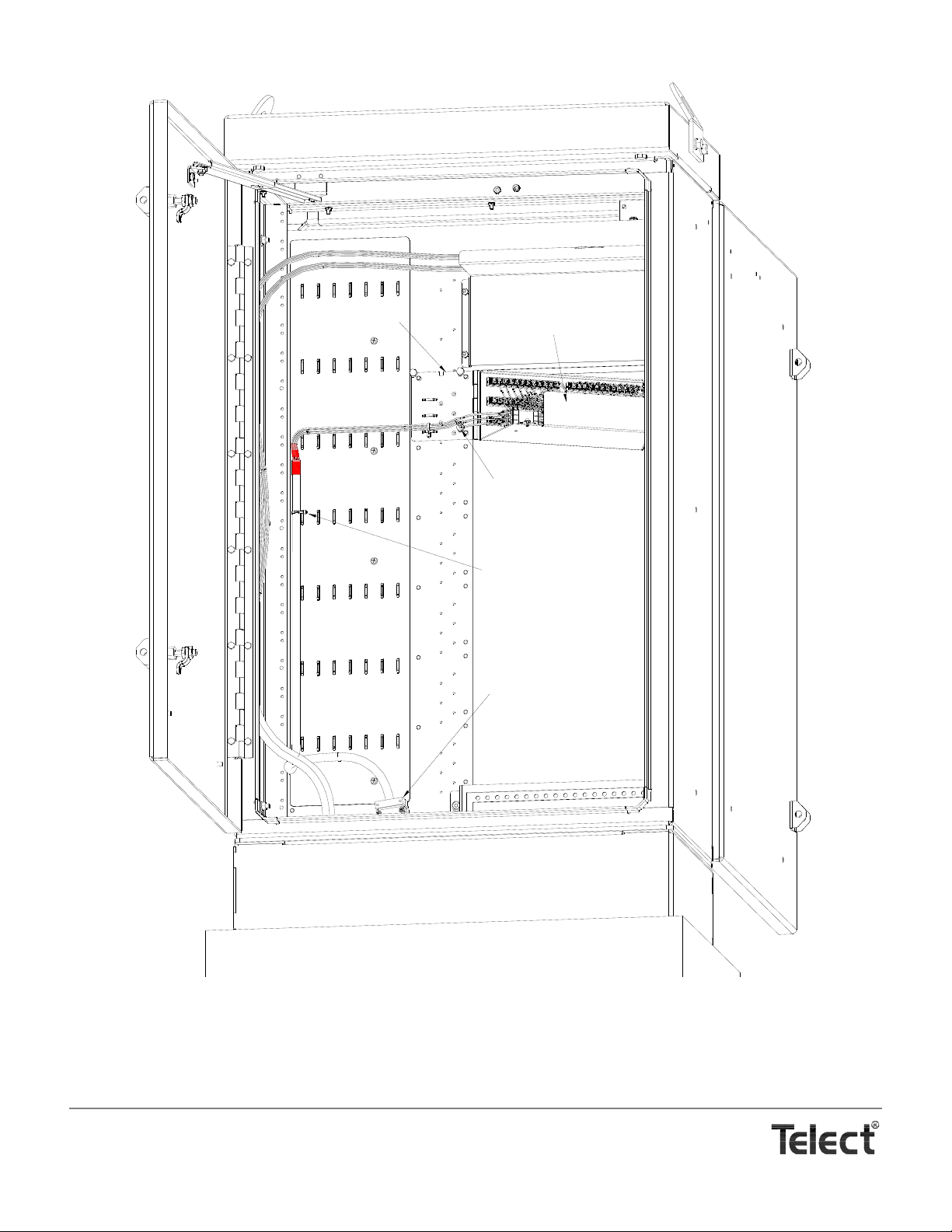
Temporarily Secure
Breakout End to
Tie-Down Wall
Move Cable Clamp to Bottom
of Cabinet
Swing Out Hinged Bulkhead
and Pass Through Rack into
Front Compartment
Use Three Acorn Nuts
Provided to Secure Patc h
Module to Interior Wall of
Cabinet
Anchor Plate
Installing a Patch Module
Telect, Inc. • USA +1.509.926.6000 • Mexico +1.52.33.3836.3700
Poland +1.48.713.239.100 • UK +1.44.1489.889500 • www.telect.com
Copyright © 2002 Telect, Inc., All Rights Reserved
Page 3-7
Page 26
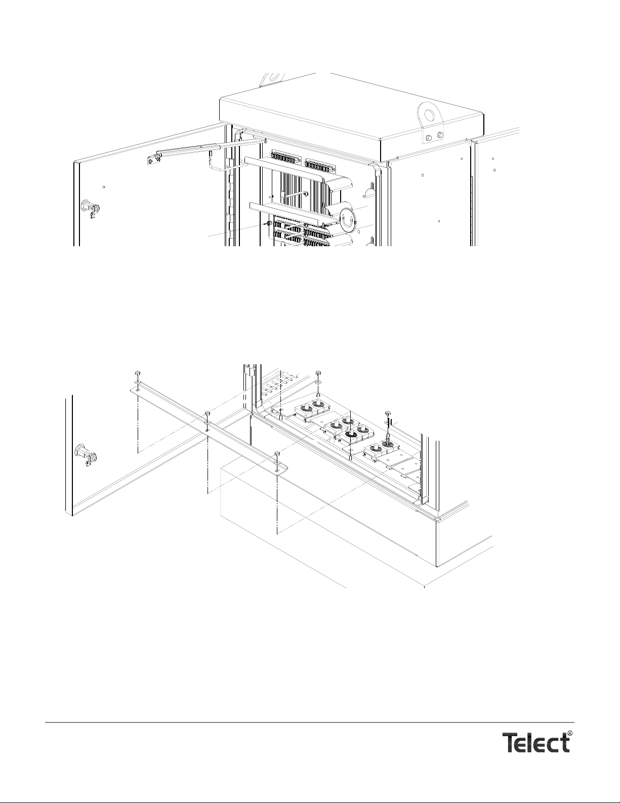
10. At front of cabinet, secure patch module swing-out door.
Thumbscrew for securing Patch Module Door
Finishing Cable Installation
11. Repeat Steps 4 through 10 for the next Patch Module and distribution cable.
12. Continue so until all scheduled Patch Modules are installed.
13. Re-insert cable entrance dock: tilt it up as shown in the following illustration, and then slip the feeder and distribution cable
clamps into the slots. Use extra clamps to fill out the slots containing only one cable.
14. Pivot the dock to the floor of the cabinet and re-install the chock bar. Push the chock bar against the cable clamps and secure.
15. Close the rear door.
Telect, Inc. • USA +1.509.926.6000 • Mexico +1.52.33.3836.3700
Poland +1.48.713.239.100 • UK +1.44.1489.889500 • www.telect.com
Copyright © 2002 Telect, Inc., All Rights Reserved
Page 3-8
Page 27

4. Cabling With In-Cabinet Splicing
WARNING
!
WARNING! Fiber ca bles transmit invi sible infrared light . To avoid eye damage or b lindness, never loo k directly
into fibers or connectors.
WARNUNG! Faserkabel übertragen unsichtbares Infrarotlicht. Um eine Schädigung der Augen oder Blindheit
zu vermeiden, schauen Sie nicht direkt in die Fasern oder Stecker.
ADVERTENCIA ! Los cables de fibra transmiten luz láser o infrarroja invisible. Para evitar lesiones oculares o
ceguera, nunca mire directamente a las fibras o conectores.
AVERTISSMENT ! Les câbles à fibres transmettent un rayon laser ou une lumière infrarouge invisible. Pour
éviter toute lésion occulaire ou cécité, ne regardez jamais directement dans les fibres ou dans les
connecteurs.
Fiber installation with on-board cabinet splicing involves installing Telect’s optional splice box and distribution patch modules in the rear compartment of the MDC-CB. The feeder and distribution cables are secured to the floor of the rear compartment. The installer routes the fiber breakout to the splice box where it’s spliced to connectorized fiber. In turn, connectorized feeder and distribution fiber is routed and then terminated to the compartment interface adapters and distribution
patch modules.
SPLICE BOX INSTALLATION
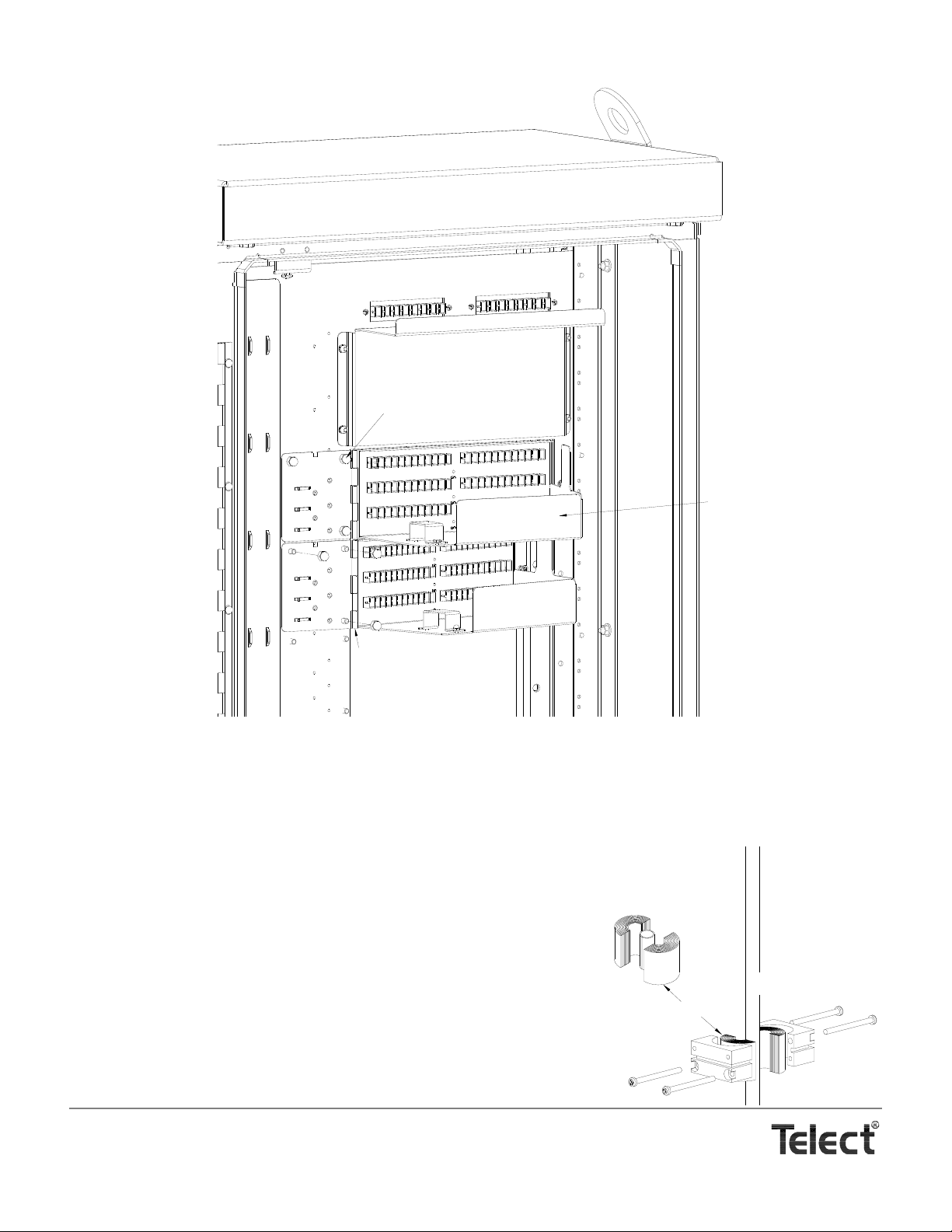
Install the Model MDC-SPLC Splice Box on the inside of the rear door using the hardware provided, as shown in the following illustration. (See “Accessories” Page 7-3.)
PATCH MODULE INSTALLATION
The Model MDC-P72N Patch Module is installed from and secured to the rear compartment. (See “Accessories” Page 7-3.)
To install, swing out the hinged bulkhead from the patch module’s anchor plate so that the bulkhead fits through rack and into front
compartment. (See the illustration on Page 4-3.) Then, secure anchor plate to partition wall using three acorn nuts provided. In the
front compartment, secure patch module swing-out door.
Install all intended patch modules before installing any cable.
Telect, Inc. • USA +1.509.926.6000 • Mexico +1.52.33.3836.3700
Poland +1.48.713.239.100 • UK +1.44.1489.889500 • www.telect.com
Copyright © 2002 Telect, Inc., All Rights Reserved • Telect Publication 131220 A0
Page 28
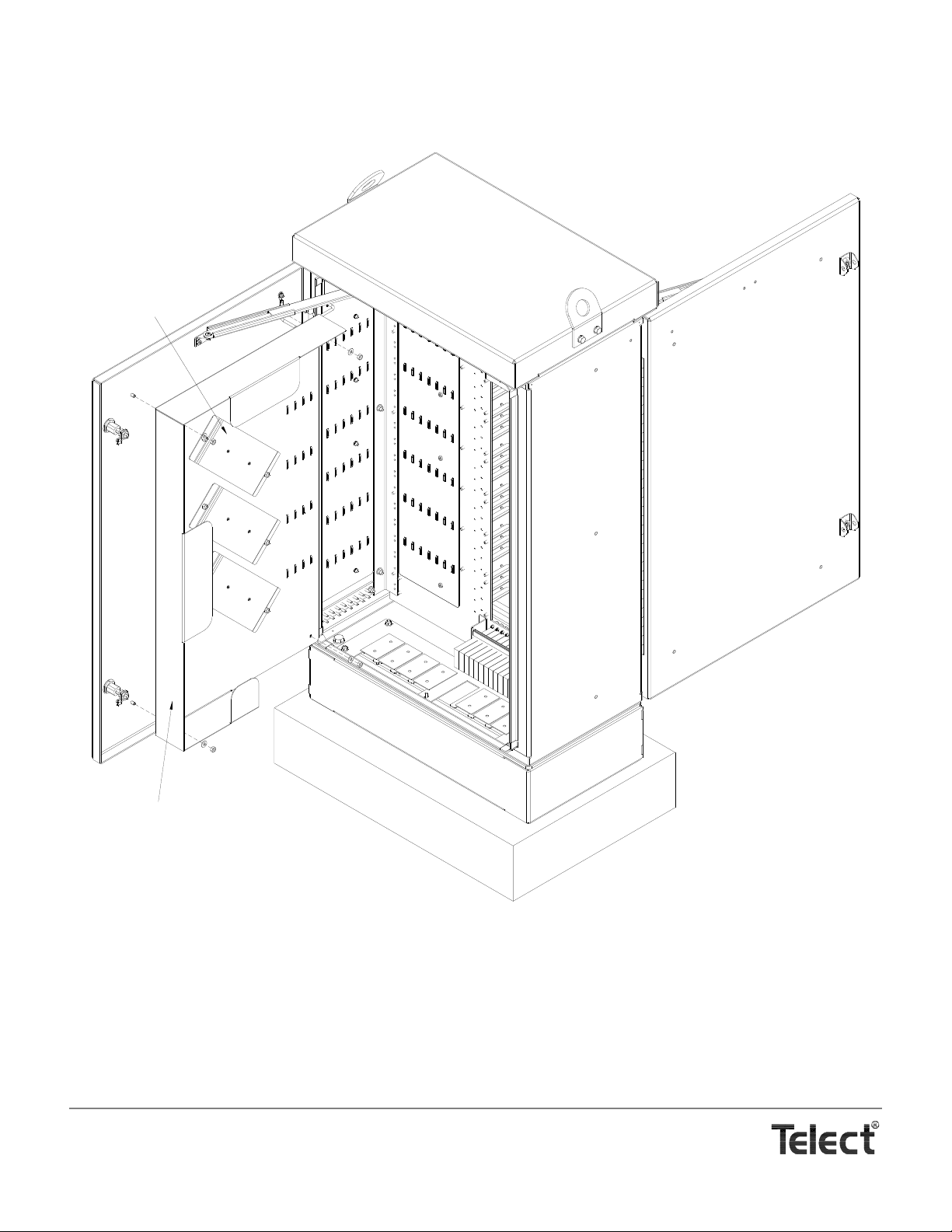
Splice Box
Cassette Holders
Installing Splice Box
Telect, Inc. • USA +1.509.926.6000 • Mexico +1.52.33.3836.3700
Poland +1.48.713.239.100 • UK +1.44.1489.889500 • www.telect.com
Copyright © 2002 Telect, Inc., All Rights Reserved
Page 4-2
Page 29
FEEDER CABLE INSTALLATION
Bulkhead Swings on Hinge
to Allow Access to Rear
Connectors and Adapters
From Front Compartment
Acorn Nuts (3) Secure Patch
Module to Rear Wall of Partition
Patch Module
Installing Model MDC-P72N Patch Module
Bushing Leaves
OSP Cable
Leaves are provided in an onion
skin roll to accommodate
multifiber cabling from .375 in. to
1.25 in. (9.5 mm to 32 mm) in dia
The cabinet accommodates up to 16 strands of OSP feeder cable. Telect sup-
3
plies two cable clamps that accommodate cables between
1
and 1
/5 in. (30.5 mm) in diameter. Each clamp, shown on the right, uses sev-
eral layers of gasket or bushing leaves to hold the cable fast between the two
halves of the clamp.
/8 in. (9.6 mm)
OSP cable can be dry or wet, armored or unarmored. To connect to adapters
in the cabinet the incoming feeder fiber needs to be spliced to fiber strands
with SC/APC connectors.
To install a feeder cable, proceed as follows:
1. Open rear door.
Telect, Inc. • USA +1.509.926.6000 • Mexico +1.52.33.3836.3700
Poland +1.48.713.239.100 • UK +1.44.1489.889500 • www.telect.com
Copyright © 2002 Telect, Inc., All Rights Reserved
Page 4-3
Page 30
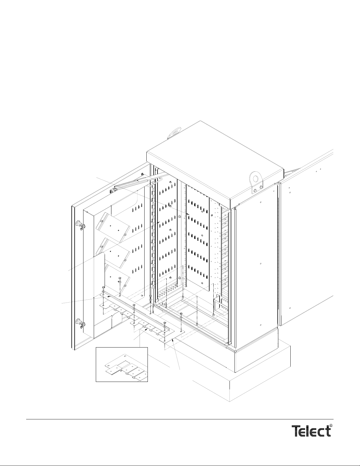
2. Remove cable entrance dock at bottom of cabinet by removing six sets of nuts and washers shown in the following illustrations.
Cable Entrance Dock
Cover Plates
Chock Bar
Distribution Tie-Down Wall
Tie-Down Wall for
Incoming Feeder &
Distribution Fiber in
Loose Tubing
The cable entrance dock contains eight slots with slide-out cover plates. Each slots can accommodate two cable clamps for either feeder or distribution cable.
3. Slide out cover plate over feeder stub up.
4. Fish feeder cable into cabinet and then remove at least 15 ft (~5 m) of sheathing from the cabinet end.
NOTE
15 ft allows the feeder fiber to reach the furthest splice cassette. Break out more buffer/subunit if you intend to splice anywhere
but at ground level at the open rear door. Add multiples of 8½ ft (~2.5 m) when adding to this length if the splicing is done, for
example, in a vehicle. The multiple represents the perimeter around the splice box for storing the excess length of tubing.
Telect, Inc. • USA +1.509.926.6000 • Mexico +1.52.33.3836.3700
Poland +1.48.713.239.100 • UK +1.44.1489.889500 • www.telect.com
Copyright © 2002 Telect, Inc., All Rights Reserved
Page 4-4
Page 31
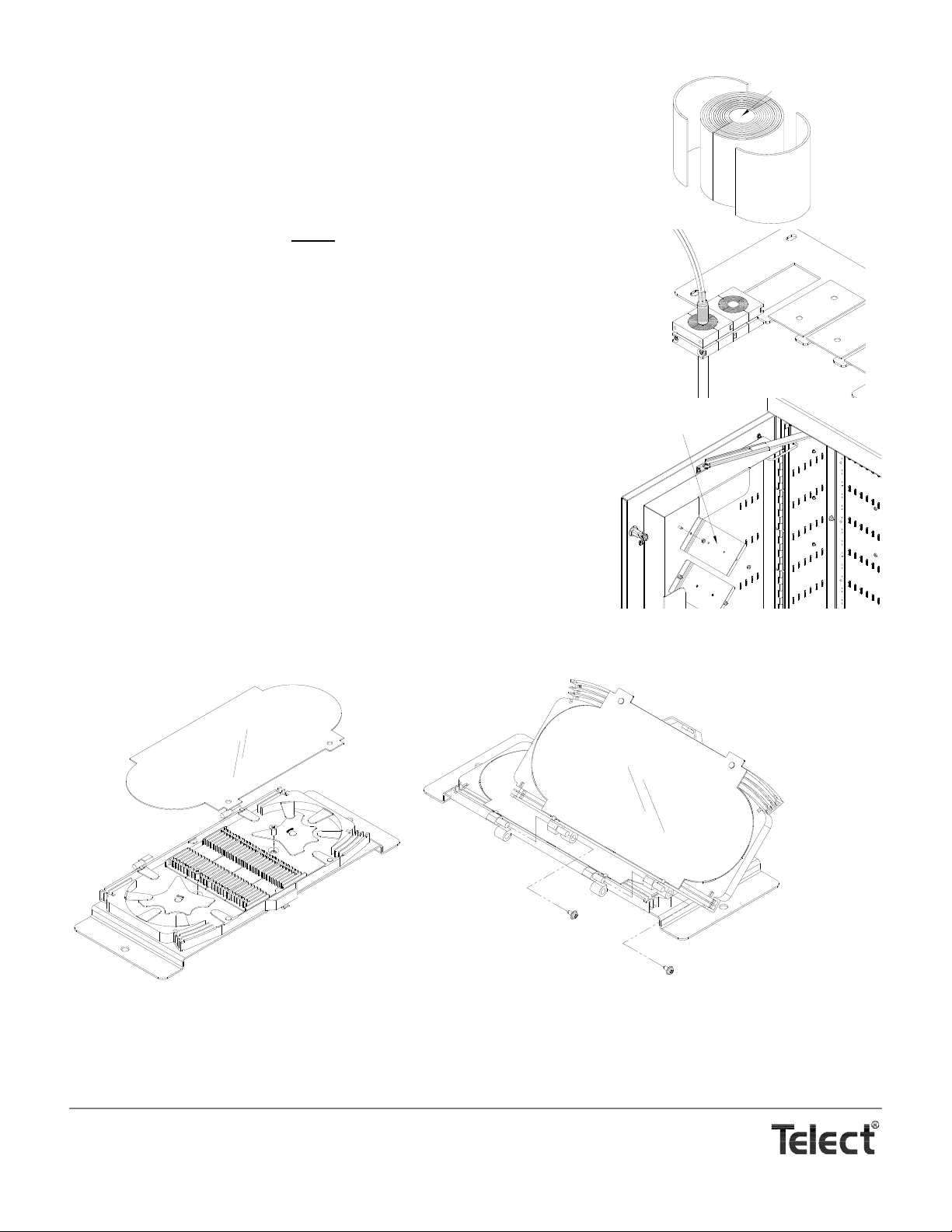
5. Carefully remove buffer/subunit tubes from the 15-foot unsheathe d end and place fiber
Bushing Leaf
Solid Core (Discard)
Brackets Will Hold a Pod
of Splice Cassettes to
the Splice Box
Installing Cassettes
First Cassette Adding Cassettes
into 3-m radius-control (bend limiting) loose tubing. Use heat-shrink tubing to hold loose
tubing to sheathed end of feeder cable.
6. Measure diameter of cables and remove and discard that much from the interior of the cable clamp’s leaf bundle equal to the diameter of the cables. The remaining leaves will be
used between the clamp halves and the cable.
7. At end of heat-shrink on cable, loosely
secure the leaf bundle(s) and clamp
halves to the cable(s), as shown in the illustration at the start of this procedure.
8. Place cable entrance dock at bottom of cabinet and slip on cable clamps, as
shown on the right.
If you have only one feeder cable to install, you must use the other cable clamp to
fill out the slot.
9. Hold down or temporarily fasten dock to cabinet.
10. Remove top cassette holder on splice box, as shown on the right. Save the two
nuts
11. Place holder on a splice cart or other convenient work surface.
12. Remove and save two screws near center of holder.
13. Remove transparent cover of cassette.
14. Use the two screws to secure the first (bottom most) splice cassette to the bracket, as shown in the next illustration.
15. Add more cassettes, as shown.
Each plastic cassette has molded in pairs of male and female hinge halves. The
female part of the hinge of the top cassette mates with the male part on the cassette below. Two collar screws, supplied with each cassette, secure the hinge.
Telect, Inc. • USA +1.509.926.6000 • Mexico +1.52.33.3836.3700
Poland +1.48.713.239.100 • UK +1.44.1489.889500 • www.telect.com
Copyright © 2002 Telect, Inc., All Rights Reserved
Page 4-5
Page 32
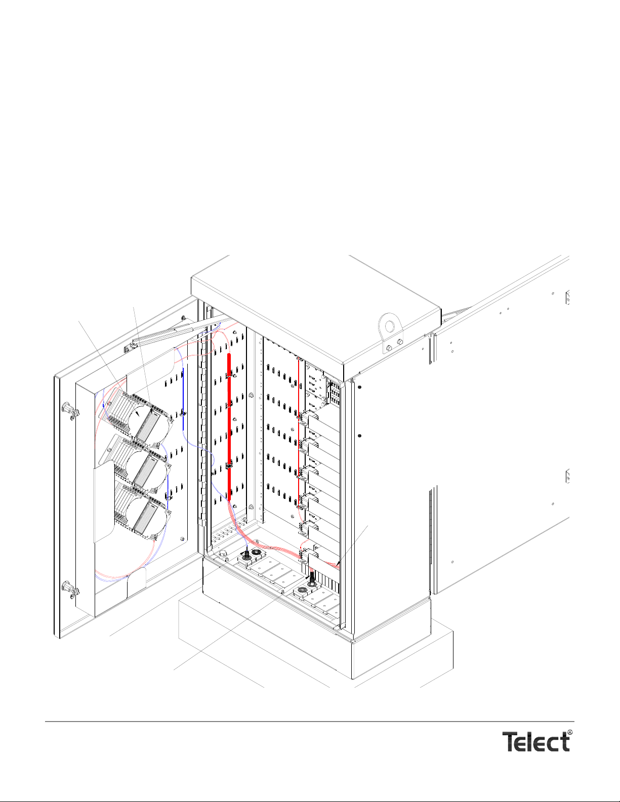
NOTE
Feeder Cable Entrance
Distribution Cable Entrance
Cassette Pod
Cassette Label
All feeder fiber is in 3-mm,
radius-control loose tubing between
feeder cable entrance and
connectorized splice.
All distribution fiber is in 3-mm,
radius-control loose tubing between
distribution cable entrance and the
connectorized fan out at the patch
module.
NOTES
Fiber strands
furcated to 900
µm
loose tubing
Routing Feeder & Distribution Loose Tubing (Overall View)
How many cassettes to place on each holder depends on how many feeder and distribution fiber pairs require splicing. If you intend to accommodate 16 (max.) signals from the CO and up to 432 (max.) from the distribution, you need a total of 19 cassettes: one for the feeders and 18 for the distribution. It’s wisest to arrange cassettes more or less evenly among the holde rs.
It’s also wisest to add all intended cassettes to the stack before running loose tubing and splicing any of the cassettes.
Normally, each cassette holds up to 24 splices. If desired, up to 48 splices will fit each cassette in two layers of 24 — 24 lower
and 24 upper. Two layers makes for a crowd cassette, howeve r, but lessens the number of cassettes overall.
16. After completing a stack of cassettes (a cassette pod), check the length of loose tubing required to reach the cassette. The following illustrations show the shortest and longest required paths for tubing.
The distance between the feeder cable breakout at the cable entrance and the cassette entrance will vary from 5 to 8 ft (~1.5 to
~2.5 m) depending on the starting and ending points in the cabinet and on the door. Check the distance and add in multiples of
8½ ft (~2.5 m), if desired, and then carefully cut off the excess tubing, being mindful of the fiber strands within. DON’T CUT
THROUGH THE FIBER because you will need an additional 3 ft (~1 m) beyond that point for the unprotected strands which will
be in the cassette. So, 3 ft (~1 m) passed the end of the loose tubing, cut away the excess fiber.
Telect, Inc. • USA +1.509.926.6000 • Mexico +1.52.33.3836.3700
Poland +1.48.713.239.100 • UK +1.44.1489.889500 • www.telect.com
Copyright © 2002 Telect, Inc., All Rights Reserved
Page 4-6
Page 33
Telect, Inc. • USA +1.509.926.6000 • Mexico +1.52.33.3836.3700
Poland +1.48.713.239.100 • UK +1.44.1489.889500 • www.telect.com
Copyright © 2002 Telect, Inc., All Rights Reserved
Page 4-7
Page 34
T
ray No
.
:
Po
s
.De
sig
n
a
t
io
n
1
2
3
4
5
6
7
8
9
10
1
1
12
1
3
1
4
1
5
1
6
1
7
1
8
1
9
2
0
2
1
22
23
24
Tra
y
N
o.:
Pos. Design
a
tion
1
2
3
4
5
6
7
8
9
1
0
11
1
2
13
14
15
16
17
18
19
2
0
21
22
23
24
T
ray No
.:
Pos. De
sig
n
atio
n
1
2
3
4
5
6
7
8
9
10
11
12
13
14
15
16
17
18
19
2
0
21
22
2
3
24
Feeder Adapters
Patch Module
Fiber From Right End of
Each Cassette to Patch
Panels Must Be in 3-mm,
Radius-Control Loose
Tubing
All Fiber From Cable Entrance to the Left
End of Each Cassette Must be in 3-mm
Radius- Control Loose Tubing
Each Fiber From
Right End of Each
Cassette to the
Feeder Adapters
Must Be in 3-mm,
Radius-Control Loose
Tubing
Left En
d
Ri
g
h
t
E
n
d
FRONT
REAR
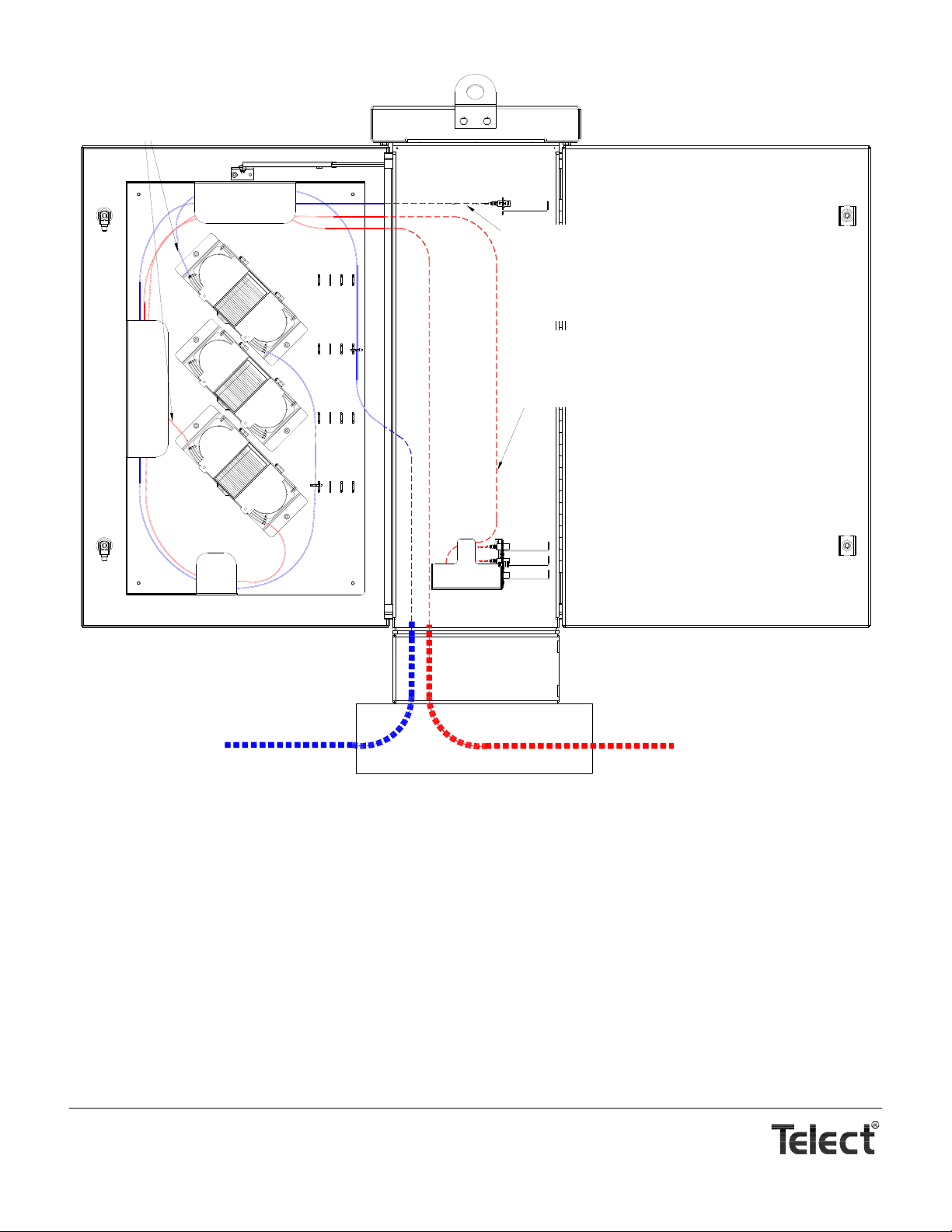
Routing Feeder & Distribution Loose Tubing (Left View of Rear Door)
17. Feed connectorized feeder interface fiber through loose tubing.
18. Secure ends of both feeder tubes at opposite entrances to the cassette, as shown in the following illustration.
19. Route fiber around the perimeter, trim excess, slip on heat-shrink fusion splice sleeve, and splice all fibers from the installed
tubes.
20. Record terminations on designation label included with cassette.
21. Finish all feeder splices before installing and splicing distribution fiber.
Telect, Inc. • USA +1.509.926.6000 • Mexico +1.52.33.3836.3700
Poland +1.48.713.239.100 • UK +1.44.1489.889500 • www.telect.com
Copyright © 2002 Telect, Inc., All Rights Reserved
Page 4-8
Page 35
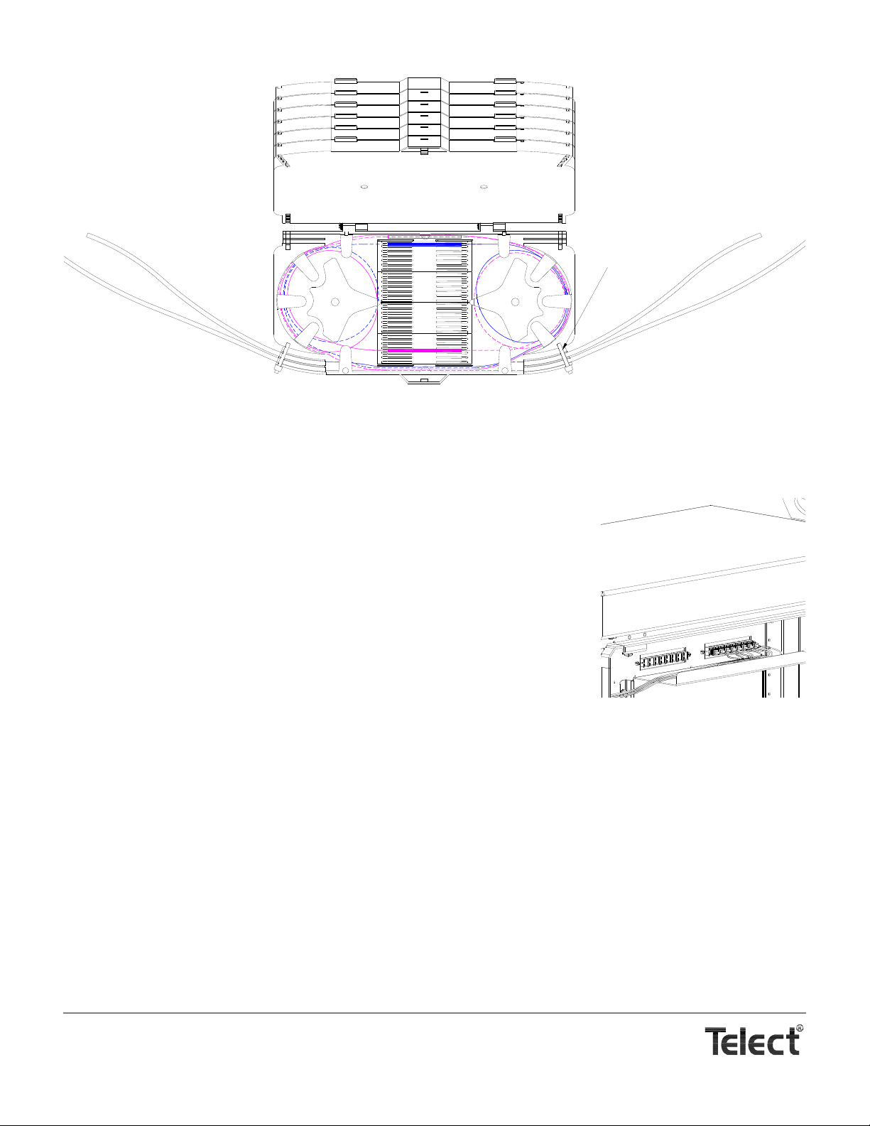
22. Apply the designation label to the cassette cover and connect ends of fiber into adapters
1
2
3
4
5
6
7
8
9
10
11
12
13
14
15
16
17
18
19
20
21
22
23
24
1
2
3
4
5
6
7
8
9
10
11
12
13
14
15
16
17
18
19
20
21
22
23
24
To/From
Cable Entrance
To/From
Feeder Interface
Cable Ties at
Cassette Entrances
Fiber from cable entrance to Splice Positions 1
through 12 will be at the right end of the splice.
Fiber from cable entrance to Splice Positions 13
through 24 will be at the left end of the splice.
Fiber from feeder interface to Splice Positions 1
through 12 will be at the left end of the splice.
Fiber from cable entrance to Splice Positions 13
through 24 will be at the right end of the splice.
Routing Fiber in a Cassette
on the feeder interface shown on the right.
23. Continue with “Distribution Cable Installation” in the next section before installing the pod
on the door and before securing tubing to the cabinet and door. Do not mix feeder and
distribution splices in the same cassette.
DISTRIBUTION CABLE INSTALLATION
The cabinet accommodates up to 432 strands of OSP distribution cable.
Telect does not include cable clamps for the distribution cable. The cable clamps are the same
type used for the feeder cables. See “Accessories” on Page 7-2.
Like the feeder cable, OSP distribution cable can be dry or wet, armored or unarmored. To connect to adapters in the patch module,
the incoming distribution fiber needs to be spliced to fiber strands with SC/APC connectors.
The breakout, splicing, and routing of distribution is similar to that of the feeder. In brief,
1. As before, remove at least 15 ft (~2.5 m) of sheathing from the distribution cable entering the cabinet. More, if desired, in 8½ ft
(~2.5 m) increments. Also remove the buffer/subunit tube covering the fiber and slip on 3-mm, radius control loose tubing.
2. Heat shrink tubing to cable at entrance dock and then attach a cable clamp
3. Check the length of loose tubing required for the run between the cassette and the fan-out block on the patch module.
The distance will vary from 6¾ to 9¾ ft (~2 to 3 m) depending on the starting point on the door and the location of the patch
module. Check the distance and add in multiples of 8½ ft (~2.5 m), if desired, to determine tubing length. For the fiber, you will
need this length plus an additional 4 ft (~1.25 m) beyond that point for the unprotected strands which will be in the cassette and
for the fiber from the entrance of the fan-out block to the adapter on the patch module.
4. For each loose tube of 12 fibers, you will need a fan-out block to adapt the fiber in one loose tube to individual fibers in a 900 µm
loose tubes.
Telect, Inc. • USA +1.509.926.6000 • Mexico +1.52.33.3836.3700
Poland +1.48.713.239.100 • UK +1.44.1489.889500 • www.telect.com
Copyright © 2002 Telect, Inc., All Rights Reserved
Page 4-9
Page 36
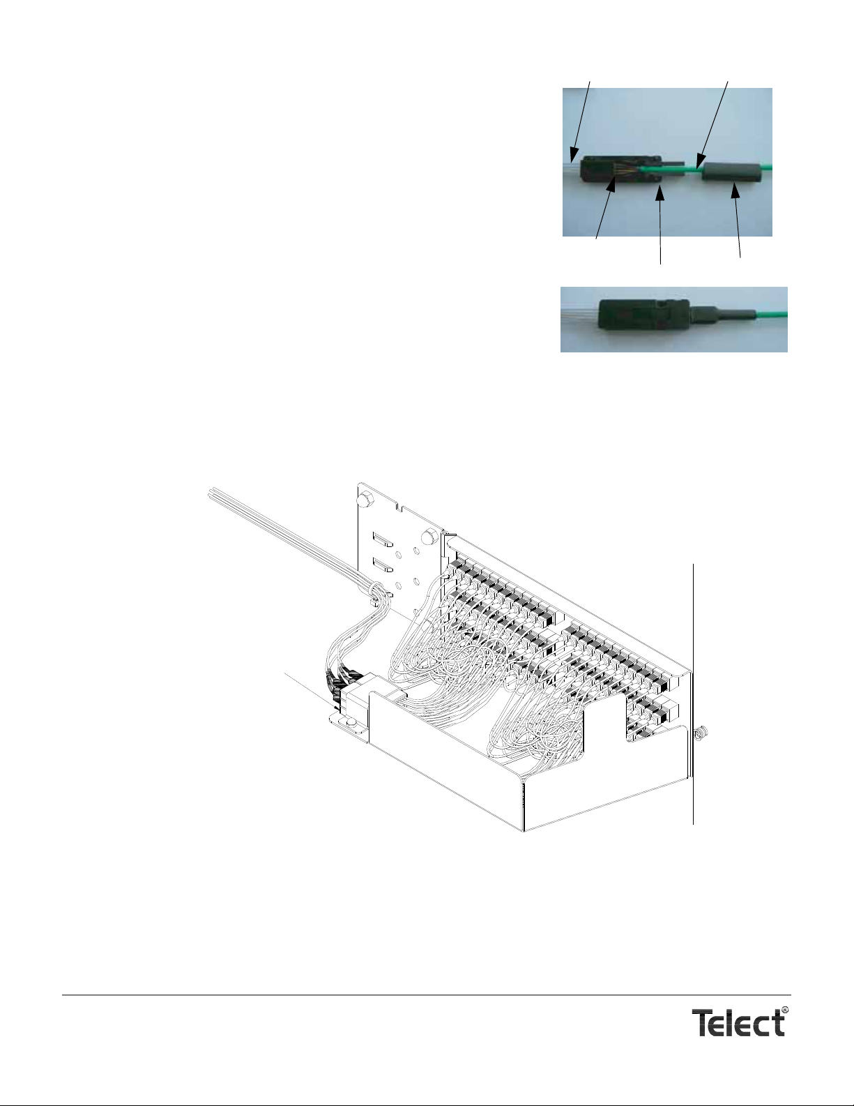
To use the fan-out block, proceed as follows:
Transparent Tubes
Furcation Block
Heat-Shrink Tube
Loose Tubing
Bottom Cover
6 Fan-Out Blocks
Per Patch Module
a. The furcation block has about 1.5 m (~5 ft) of transparent tubing for 900 µm fi-
bers. Cut the transparent tubing back to 11½ in.(~300 mm).
b. Slip the fibers through the furcation block and transparent tubes and move the
ends of the transparent tubes up to the SC/APC connectors.
c. Next, slip on the heat-shrink tube supplie d with the fan-out kit
d. Place the furcation block onto the bottom cover.
e. Snap on the top cover.
f. Slide up the heat-shrink tube against the block and heat shrink.
5. Secure ends of both distribution tubes at opposite entrances to the cassette, route
fiber throughout cassette (Page 4-9), trim excess, slip on splice sleeve, and splice.
6. Record terminations on designation label included with cassette.
7. Finish all splices in a cassette before moving to the next.
8. Continue with the remainder of the fibers from the distribution cable — splicing them to connectorized fibers — before moving to
the next cable.
After every 72 fibers (6 fan-out blocks), connect ends of fiber into adapters on the patch module, shown in the following illustration. Use the bracket provided on the patch module to secure the fan-out blocks to the patch module chassis.
9. Complete all cassettes in a pod before mounting the pod to the rear door and before routing the loose tubing.
Telect, Inc. • USA +1.509.926.6000 • Mexico +1.52.33.3836.3700
Poland +1.48.713.239.100 • UK +1.44.1489.889500 • www.telect.com
Copyright © 2002 Telect, Inc., All Rights Reserved
Page 4-10
Page 37
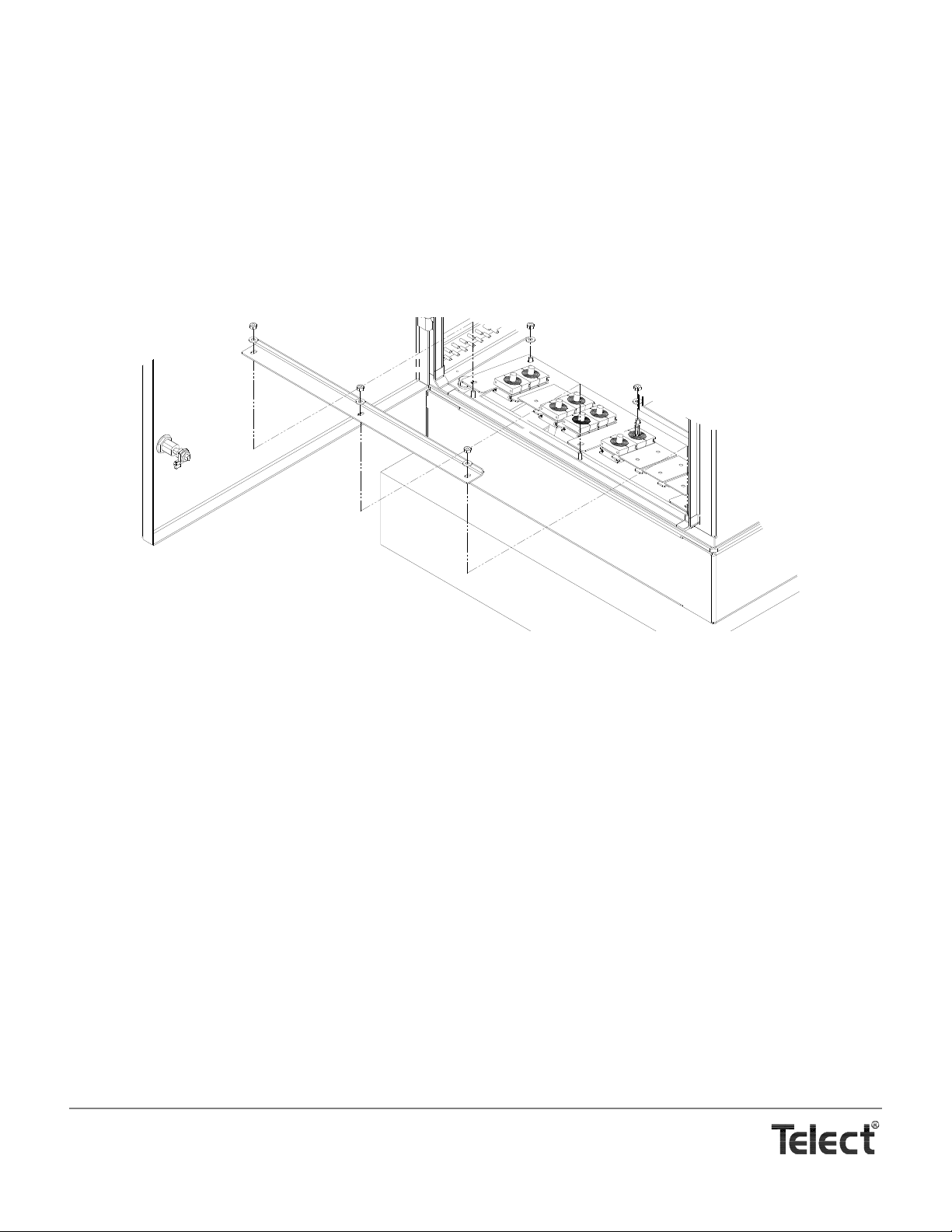
ROUTING FEEDER & DISTRIBUTION LOOSE TUBING
When completed and before moving to the next cassette pod,
1. Install completed cassette pod on the rear door.
2. Route all loose tubing as planned and use cable ties liberally to secure tubing to lances on door and in cabinet.
3. After all feeder and distribution cabling and loose tubing has been installed, spliced, and routed, re-insert cable entrance dock,
tilt it up as shown in the following illustration, and then slip the feeder and distribution cable clamps into the slots. Use extra
clamps to fill out the slots containing only one cable.
4. Pivot the dock to the floor of the cabinet and re-install the chock bar. Push the chock bar against the cable clamps.
5. Secure the chock bar and close the rear door.
Telect, Inc. • USA +1.509.926.6000 • Mexico +1.52.33.3836.3700
Poland +1.48.713.239.100 • UK +1.44.1489.889500 • www.telect.com
Copyright © 2002 Telect, Inc., All Rights Reserved
Page 4-11
Page 38

Telect, Inc. • USA +1.509.926.6000 • Mexico +1.52.33.3836.3700
Poland +1.48.713.239.100 • UK +1.44.1489.889500 • www.telect.com
Copyright © 2002 Telect, Inc., All Rights Reserved
Page 4-12
Page 39
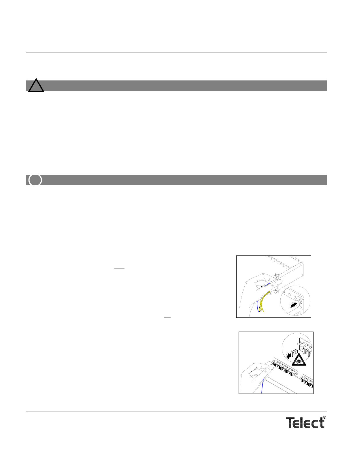
5. Cross Connections
WARNING
!
ALERT
!
Installing Splitter Module
Connecting to Feeder
WARNING! Fiber c ables transmit la ser or invisible infr ared light . To avoid eye damage or blindness, never look
directly into fibers or connections.
WARNUNG! Faserkabel übertragen unsichtbares Infrarotlicht. Um eine Schädigung der Augen oder Blindheit
zu vermeiden, schauen Sie nicht direkt in die Fasern oder Stecker.
ADVERTENCIA ! Los cables de fibra transmiten luz láser o infrarroja invisible. Para evitar lesiones oculares o
ceguera, nunca mire directamente a las fibras o conectores.
AVERTISSMENT ! Les câbles à fibres transmettent un rayon laser ou une lumière infrarouge invisible. Pour
éviter toute lésion occulaire ou cécité, ne regardez jamais directement dans les fibres ou dans les
connecteurs.
ALERT! This product must be installed and maintained by qualified technicians.
After installing all feeder and distribution cabling in the rear compartment, close the rear compartment. All subscriber
changes are done in the front compartment. First, however, the high-intensity feeder signals needs to be split before cross
connecting to the distribution.
Telect Splitter Modules are installed, interconnected to the incoming feeder fiber, and cross connected to distribution fiber in the front
compartment. After installing OSP cable, the rear compartment need not be re-opened.
Telect manufactures four Splitter Module configurations for this cabinet: 1 x 4, 1 x 8, 1 x 16, and 1 x 32.
To install a Splitter Module, proceed as follows:
1. Start at Splitter Position 18 on the right
bottom of front compartment.
2. As shown in the illustration on the right, push in the two plunger-style latches to secure the module.
The splitter module has one blue 2-mm jumper for the feed-in and 4, 8, 16, or 32
yellow 2-mm jumpers for the distribution. All splitter jumpers are 2.1 m in length.
3. Route the blue jumper to the first feeder adapter on the left
compartment, as shown in the illustration on the right.
Going from right most splitter module to left most feeder adapter guarantees that
the blue jumpers from all splitter modules will neatly fit the same pathway around
the routing arcs and spools in the right half of the compartment. Prefer to route
the blue jumpers as shown in the following illustration, that is, around the bottom,
right most spool, up to the nearest arc, down around the bottom most spool to the
left of the other, and on up to the feeder bulkhead.
and insert module in splitter bulkhead near
at the top of the front
Telect, Inc. • USA +1.509.926.6000 • Mexico +1.52.33.3836.3700
Poland +1.48.713.239.100 • UK +1.44.1489.889500 • www.telect.com
Copyright © 2002 Telect, Inc., All Rights Reserved • Telect Publication 131220 A0
Page 40
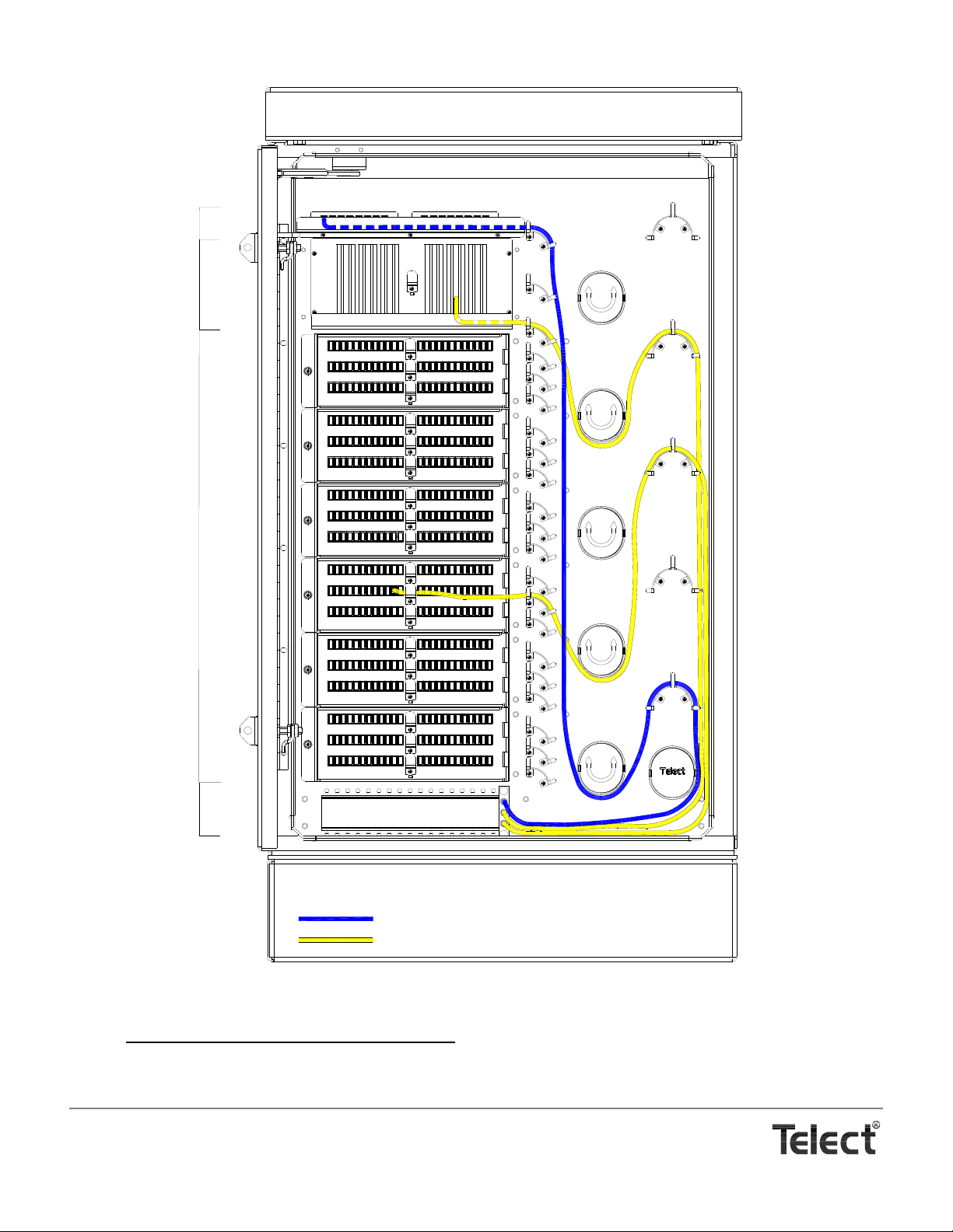
Feeder Cable to Splitter
Assigned & Unassigned Distribution Cable
Feeders
Assigned
Distribution
to Subscriber
Unassigned
Distribution
(Parking)
Splitter
Bulkhead
1
25
49
2
26
50
3
27
51
4
28
52
5
29
53
6
30
54
7
31
55
8
32
56
9
33
57
10
34
58
11
35
59
12
36
60
13
37
61
14
38
62
15
39
63
16
40
64
17
41
65
18
42
66
19
43
67
20
44
68
21
45
69
22
46
70
23
47
71
24
48
72
1
25
49
2
26
50
3
27
51
4
28
52
5
29
53
6
30
54
7
31
55
8
32
56
9
33
57
10
34
58
11
35
59
12
36
60
13
37
61
14
38
62
15
39
63
16
40
64
17
41
65
18
42
66
19
43
67
20
44
68
21
45
69
22
46
70
23
47
71
24
48
72
1
25
49
2
26
50
3
27
51
4
28
52
5
29
53
6
30
54
7
31
55
8
32
56
9
33
57
10
34
58
11
35
59
12
36
60
13
37
61
14
38
62
15
39
63
16
40
64
17
41
65
18
42
66
19
43
67
20
44
68
21
45
69
22
46
70
23
47
71
24
48
72
1
25
49
2
26
50
3
27
51
4
28
52
5
29
53
6
30
54
7
31
55
8
32
56
9
33
57
10
34
58
11
35
59
12
36
60
13
37
61
14
38
62
15
39
63
16
40
64
17
41
65
18
42
66
19
43
67
20
44
68
21
45
69
22
46
70
23
47
71
24
48
72
1
25
49
2
26
50
3
27
51
4
28
52
5
29
53
6
30
54
7
31
55
8
32
56
9
33
57
10
34
58
11
35
59
12
36
60
13
37
61
14
38
62
15
39
63
16
40
64
17
41
65
18
42
66
19
43
67
20
44
68
21
45
69
22
46
70
23
47
71
24
48
72
1
25
49
2
26
50
3
27
51
4
28
52
5
29
53
6
30
54
7
31
55
8
32
56
9
33
57
10
34
58
11
35
59
12
36
60
13
37
61
14
38
62
15
39
63
16
40
64
17
41
65
18
42
66
19
43
67
20
44
68
21
45
69
22
46
70
23
47
71
24
48
72
12345678
9 10111213141516
1 2 3 4 5 6 7 8 9 1 0 11 12 13 14 15 16 17 18
Distribution Routing
4. Now route the yellow jumpers for assigned and unassigned distribution:
Telect, Inc. • USA +1.509.926.6000 • Mexico +1.52.33.3836.3700
Poland +1.48.713.239.100 • UK +1.44.1489.889500 • www.telect.com
Copyright © 2002 Telect, Inc., All Rights Reserved
• For assigned distribution (connecting to a subscriber)
tom, and then up to and around one of the four arcs directly above, as shown in the illustration. Pick one of the arcs above
, route the cables to the right, around the right most spool at the bot-
the intended patch. (Always reserve the top most arc and spool for as yet unassigned cable and for dropped subscribers.)
Page 5-2
Page 41
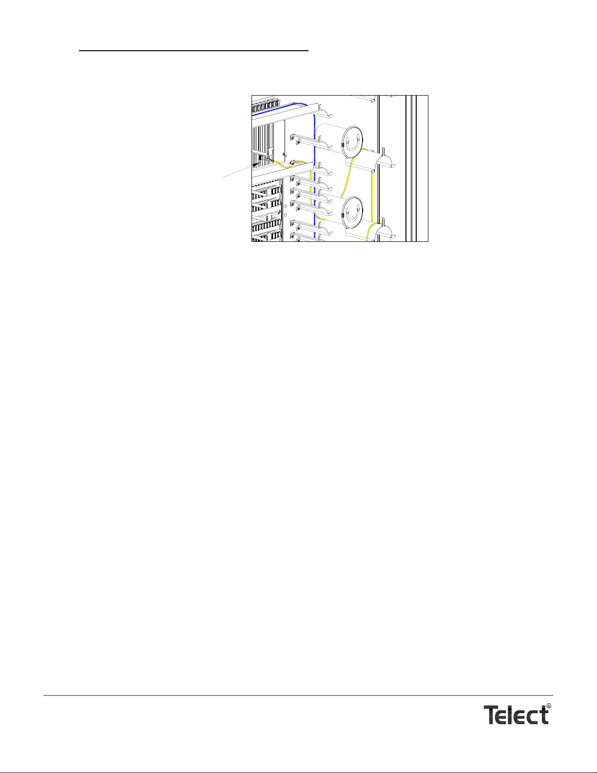
• For unassigned distribution or for disconnected subscribers, route the cable up and around one of the top two arcs and
Parking Unassigned Distribution Jumpers
Parking for
Unassigned
Distribution
spools and then plug the connector (with dust cover attached) into one of the rubber holders between the feeders and the
Patch Modules, as shown in the illustration.
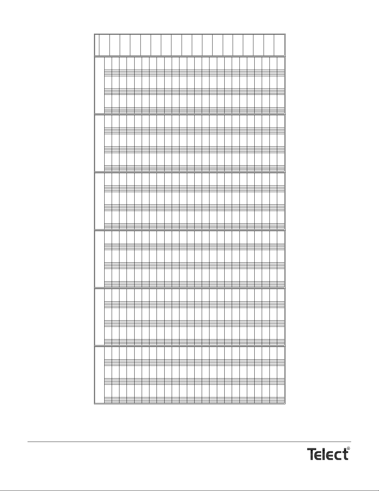
5. Record splitter and subscriber assignments on the erasable label applied to the inside of the front door.
A replica of the designation label is shown in the following illustration.
Telect, Inc. • USA +1.509.926.6000 • Mexico +1.52.33.3836.3700
Poland +1.48.713.239.100 • UK +1.44.1489.889500 • www.telect.com
Copyright © 2002 Telect, Inc., All Rights Reserved
Page 5-3
Page 42
1
FIBER
CABLE
2
FIBER
CABLE
3
FIBER
CABLE
4
FIBER
CABLE
5
FIBER
CABLE
6
FIBER
CABLE
7
FIBER
CABLE
8
FIBER
CABLE
9
FIBER
CABLE
10
FIBER
CABLE
11
FIBER
CABLE
12
FIBER
CABLE
13
FIBER
CABLE
14
FIBER
CABLE
15
FIBER
CABLE
16
FIBER
CABLE
17
FIBER
CABLE
18
FIBER
CABLE
19
FIBER
CABLE
20
FIBER
CABLE
21
FIBER
CABLE
22
FIBER
CABLE
23
FIBER
CABLE
24
FIBER
CABLE
25
FIBER
CABLE
26
FIBER
CABLE
27
FIBER
CABLE
28
FIBER
CABLE
29
FIBER
CABLE
30
FIBER
CABLE
31
FIBER
CABLE
32
FIBER
CABLE
33
FIBER
CABLE
34
FIBER
CABLE
35
FIBER
CABLE
36
FIBER
CABLE
37
FIBER
CABLE
38
FIBER
CABLE
39
FIBER
CABLE
40
FIBER
CABLE
41
FIBER
CABLE
42
FIBER
CABLE
43
FIBER
CABLE
44
FIBER
CABLE
45
FIBER
CABLE
46
FIBER
CABLE
47
FIBER
CABLE
48
FIBER
CABLE
49
FIBER
CABLE
50
FIBER
CABLE
51
FIBER
CABLE
52
FIBER
CABLE
53
FIBER
CABLE
54
FIBER
CABLE
55
FIBER
CABLE
56
FIBER
CABLE
57
FIBER
CABLE
58
FIBER
CABLE
59
FIBER
CABLE
60
FIBER
CABLE
61
FIBER
CABLE
62
FIBER
CABLE
63
FIBER
CABLE
64
FIBER
CABLE
65
FIBER
CABLE
66
FIBER
CABLE
67
FIBER
CABLE
68
FIBER
CABLE
69
FIBER
CABLE
70
FIBER
CABLE
71
FIBER
CABLE
72
FIBER
CABLE
PANEL
1
FIBERS
1-72
73
FIBER
CABLE
74
FIBER
CABLE
75
FIBER
CABLE
76
FIBER
CABLE
77
FIBER
CABLE
78
FIBER
CABLE
79
FIBER
CABLE
80
FIBER
CABLE
81
FIBER
CABLE
82
FIBER
CABLE
83
FIBER
CABLE
84
FIBER
CABLE
85
FIBER
CABLE
86
FIBER
CABLE
87
FIBER
CABLE
88
FIBER
CABLE
89
FIBER
CABLE
90
FIBER
CABLE
91
FIBER
CABLE
92
FIBER
CABLE
93
FIBER
CABLE
94
FIBER
CABLE
95
FIBER
CABLE
96
FIBER
CABLE
97
FIBER
CABLE
98
FIBER
CABLE
99
FIBER
CABLE
100
FIBER
CABLE
101
FIBER
CABLE
102
FIBER
CABLE
103
FIBER
CABLE
104
FIBER
CABLE
105
FIBER
CABLE
106
FIBER
CABLE
107
FIBER
CABLE
108
FIBER
CABLE
109
FIBER
CABLE
110
FIBER
CABLE
111
FIBER
CABLE
112
FIBER
CABLE
113
FIBER
CABLE
114
FIBER
CABLE
115
FIBER
CABLE
116
FIBER
CABLE
117
FIBER
CABLE
118
FIBER
CABLE
119
FIBER
CABLE
120
FIBER
CABLE
121
FIBER
CABLE
122
FIBER
CABLE
123
FIBER
CABLE
124
FIBER
CABLE
125
FIBER
CABLE
126
FIBER
CABLE
127
FIBER
CABLE
128
FIBER
CABLE
129
FIBER
CABLE
130
FIBER
CABLE
131
FIBER
CABLE
132
FIBER
CABLE
133
FIBER
CABLE
134
FIBER
CABLE
135
FIBER
CABLE
136
FIBER
CABLE
137
FIBER
CABLE
138
FIBER
CABLE
139
FIBER
CABLE
140
FIBER
CABLE
141
FIBER
CABLE
142
FIBER
CABLE
143
FIBER
CABLE
144
FIBER
CABLE
PANEL
2
FIBERS
73-144
145
FIBER
CABLE
146
FIBER
CABLE
147
FIBER
CABLE
148
FIBER
CABLE
149
FIBER
CABLE
150
FIBER
CABLE
151
FIBER
CABLE
152
FIBER
CABLE
153
FIBER
CABLE
154
FIBER
CABLE
155
FIBER
CABLE
156
FIBER
CABLE
157
FIBER
CABLE
158
FIBER
CABLE
159
FIBER
CABLE
160
FIBER
CABLE
161
FIBER
CABLE
162
FIBER
CABLE
163
FIBER
CABLE
164
FIBER
CABLE
165
FIBER
CABLE
166
FIBER
CABLE
167
FIBER
CABLE
168
FIBER
CABLE
169
FIBER
CABLE
170
FIBER
CABLE
171
FIBER
CABLE
172
FIBER
CABLE
173
FIBER
CABLE
174
FIBER
CABLE
175
FIBER
CABLE
176
FIBER
CABLE
177
FIBER
CABLE
178
FIBER
CABLE
179
FIBER
CABLE
180
FIBER
CABLE
181
FIBER
CABLE
182
FIBER
CABLE
183
FIBER
CABLE
184
FIBER
CABLE
185
FIBER
CABLE
186
FIBER
CABLE
187
FIBER
CABLE
188
FIBER
CABLE
189
FIBER
CABLE
190
FIBER
CABLE
191
FIBER
CABLE
192
FIBER
CABLE
193
FIBER
CABLE
194
FIBER
CABLE
195
FIBER
CABLE
196
FIBER
CABLE
197
FIBER
CABLE
198
FIBER
CABLE
199
FIBER
CABLE
200
FIBER
CABLE
201
FIBER
CABLE
202
FIBER
CABLE
203
FIBER
CABLE
204
FIBER
CABLE
205
FIBER
CABLE
206
FIBER
CABLE
207
FIBER
CABLE
208
FIBER
CABLE
209
FIBER
CABLE
210
FIBER
CABLE
211
FIBER
CABLE
212
FIBER
CABLE
213
FIBER
CABLE
214
FIBER
CABLE
215
FIBER
CABLE
216
FIBER
CABLE
PANEL
3
FIBERS
145-216
217
FIBER
CABLE
218
FIBER
CABLE
219
FIBER
CABLE
220
FIBER
CABLE
221
FIBER
CABLE
222
FIBER
CABLE
223
FIBER
CABLE
224
FIBER
CABLE
225
FIBER
CABLE
226
FIBER
CABLE
227
FIBER
CABLE
228
FIBER
CABLE
229
FIBER
CABLE
230
FIBER
CABLE
231
FIBER
CABLE
232
FIBER
CABLE
233
FIBER
CABLE
234
FIBER
CABLE
235
FIBER
CABLE
236
FIBER
CABLE
237
FIBER
CABLE
238
FIBER
CABLE
239
FIBER
CABLE
240
FIBER
CABLE
241
FIBER
CABLE
242
FIBER
CABLE
243
FIBER
CABLE
244
FIBER
CABLE
245
FIBER
CABLE
246
FIBER
CABLE
247
FIBER
CABLE
248
FIBER
CABLE
249
FIBER
CABLE
250
FIBER
CABLE
251
FIBER
CABLE
252
FIBER
CABLE
253
FIBER
CABLE
254
FIBER
CABLE
255
FIBER
CABLE
256
FIBER
CABLE
257
FIBER
CABLE
258
FIBER
CABLE
259
FIBER
CABLE
260
FIBER
CABLE
261
FIBER
CABLE
262
FIBER
CABLE
263
FIBER
CABLE
264
FIBER
CABLE
265
FIBER
CABLE
266
FIBER
CABLE
267
FIBER
CABLE
268
FIBER
CABLE
269
FIBER
CABLE
270
FIBER
CABLE
271
FIBER
CABLE
272
FIBER
CABLE
273
FIBER
CABLE
274
FIBER
CABLE
275
FIBER
CABLE
276
FIBER
CABLE
277
FIBER
CABLE
278
FIBER
CABLE
279
FIBER
CABLE
280
FIBER
CABLE
281
FIBER
CABLE
282
FIBER
CABLE
283
FIBER
CABLE
284
FIBER
CABLE
285
FIBER
CABLE
286
FIBER
CABLE
287
FIBER
CABLE
288
FIBER
CABLE
PANEL
4
FIBERS
217-288
289
FIBER
CABLE
290
FIBER
CABLE
291
FIBER
CABLE
292
FIBER
CABLE
293
FIBER
CABLE
294
FIBER
CABLE
295
FIBER
CABLE
296
FIBER
CABLE
297
FIBER
CABLE
298
FIBER
CABLE
299
FIBER
CABLE
300
FIBER
CABLE
301
FIBER
CABLE
302
FIBER
CABLE
303
FIBER
CABLE
304
FIBER
CABLE
305
FIBER
CABLE
306
FIBER
CABLE
307
FIBER
CABLE
308
FIBER
CABLE
309
FIBER
CABLE
310
FIBER
CABLE
311
FIBER
CABLE
312
FIBER
CABLE
313
FIBER
CABLE
314
FIBER
CABLE
315
FIBER
CABLE
316
FIBER
CABLE
317
FIBER
CABLE
318
FIBER
CABLE
319
FIBER
CABLE
320
FIBER
CABLE
321
FIBER
CABLE
322
FIBER
CABLE
323
FIBER
CABLE
324
FIBER
CABLE
325
FIBER
CABLE
326
FIBER
CABLE
327
FIBER
CABLE
328
FIBER
CABLE
329
FIBER
CABLE
330
FIBER
CABLE
331
FIBER
CABLE
332
FIBER
CABLE
333
FIBER
CABLE
334
FIBER
CABLE
335
FIBER
CABLE
336
FIBER
CABLE
337
FIBER
CABLE
338
FIBER
CABLE
339
FIBER
CABLE
340
FIBER
CABLE
341
FIBER
CABLE
342
FIBER
CABLE
343
FIBER
CABLE
344
FIBER
CABLE
345
FIBER
CABLE
346
FIBER
CABLE
347
FIBER
CABLE
348
FIBER
CABLE
349
FIBER
CABLE
350
FIBER
CABLE
351
FIBER
CABLE
352
FIBER
CABLE
353
FIBER
CABLE
354
FIBER
CABLE
355
FIBER
CABLE
356
FIBER
CABLE
357
FIBER
CABLE
358
FIBER
CABLE
359
FIBER
CABLE
360
FIBER
CABLE
PANEL
5
FIBERS
289-360
361
FIBER
CABLE
362
FIBER
CABLE
363
FIBER
CABLE
364
FIBER
CABLE
365
FIBER
CABLE
366
FIBER
CABLE
367
FIBER
CABLE
368
FIBER
CABLE
369
FIBER
CABLE
370
FIBER
CABLE
371
FIBER
CABLE
372
FIBER
CABLE
373
FIBER
CABLE
374
FIBER
CABLE
375
FIBER
CABLE
376
FIBER
CABLE
377
FIBER
CABLE
378
FIBER
CABLE
379
FIBER
CABLE
380
FIBER
CABLE
381
FIBER
CABLE
382
FIBER
CABLE
383
FIBER
CABLE
384
FIBER
CABLE
385
FIBER
CABLE
386
FIBER
CABLE
387
FIBER
CABLE
388
FIBER
CABLE
389
FIBER
CABLE
390
FIBER
CABLE
391
FIBER
CABLE
392
FIBER
CABLE
393
FIBER
CABLE
394
FIBER
CABLE
395
FIBER
CABLE
396
FIBER
CABLE
397
FIBER
CABLE
398
FIBER
CABLE
399
FIBER
CABLE
400
FIBER
CABLE
401
FIBER
CABLE
402
FIBER
CABLE
403
FIBER
CABLE
404
FIBER
CABLE
405
FIBER
CABLE
406
FIBER
CABLE
407
FIBER
CABLE
408
FIBER
CABLE
409
FIBER
CABLE
410
FIBER
CABLE
411
FIBER
CABLE
412
FIBER
CABLE
413
FIBER
CABLE
414
FIBER
CABLE
415
FIBER
CABLE
416
FIBER
CABLE
417
FIBER
CABLE
418
FIBER
CABLE
419
FIBER
CABLE
420
FIBER
CABLE
421
FIBER
CABLE
422
FIBER
CABLE
423
FIBER
CABLE
424
FIBER
CABLE
425
FIBER
CABLE
426
FIBER
CABLE
427
FIBER
CABLE
428
FIBER
CABLE
429
FIBER
CABLE
430
FIBER
CABLE
431
FIBER
CABLE
432
FIBER
CABLE
PANEL
6
FIBERS
361-432
SPLITTER
1 2 3 4 5 6 7 8 9 1011121314151617 18
Designation Label
Telect, Inc. • USA +1.509.926.6000 • Mexico +1.52.33.3836.3700
Poland +1.48.713.239.100 • UK +1.44.1489.889500 • www.telect.com
Copyright © 2002 Telect, Inc., All Rights Reserved
Page 5-4
Page 43

6. Service
WARNING
!
ALERT
!
WARNING! Fiber c ables transmit la ser or invisible infr ared light . To avoid eye damage or blindness, never look
directly into fibers or connections.
WARNUNG! Faserkabel übertragen unsichtbares Infrarotlicht. Um eine Schädigung der Augen oder Blindheit
zu vermeiden, schauen Sie nicht direkt in die Fasern oder Stecker.
ADVERTENCIA ! Los cables de fibra transmiten luz láser o infrarroja invisible. Para evitar lesiones oculares o
ceguera, nunca mire directamente a las fibras o conectores.
AVERTISSMENT ! Les câbles à fibres transmettent un rayon laser ou une lumière infrarouge invisible. Pour
éviter toute lésion occulaire ou cécité, ne regardez jamais directement dans les fibres ou dans les
connecteurs.
ALERT! This product must be installed and maintained by qualified technicians.
TECHNICAL SUPPORT
By e-mail: [email protected]
By phone: 888-821-4856 or 509-921-6161
IN-WARRANTY SERVICE
Contact your Telect equipment distributor, or call a Telect Customer Service Representative:
1-800-551-4567
1-509-926-6000
Telect will repair or replace defective products within the limits of the warranty. See “Repacking for Shipment” in this section.
NOTE
Call a Customer Service Representative for a Return Material Authorization (RMA) before returning any equipment.
OUT-OF-WARRANTY SERVICE
The procedure for out-of-warranty service is the same as for in-warranty service, except that Telect charges a processing fee, and
you must submit a Purchase Order along with a Return Material Authorization (RMA) before returning equipment. Call a Customer
Service Representative for help getting these forms.
The processing fee guarantees a repair estimate and is credited against actual material and labor costs.
Telect, Inc. • USA +1.509.926.6000 • Mexico +1.52.33.3836.3700
Poland +1.48.713.239.100 • UK +1.44.1489.889500 • www.telect.com
Copyright © 2002 Telect, Inc., All Rights Reserved • Telect Publication 131220 A0
Page 44

REPACKING FOR SHIPMENT
1. Tag the equipment showing owner’s name, address, and telephone number, together with a detailed description of the problem.
2. Use the original shipping container if possible. If you do not have it, package the equipment in a way to prevent shipping damage. Include the RMA inside the container and legibly print the RMA number on the outside of the package, near the shipping
address.
3. Insure the package.
NOTE
Telect is not liable for shipping damage.
CLEANING PATCH MODULE CONNECTORS & ADAPTERS
The Patch Module adapters are mounted to a hinged bulkhead to allow access to both connectors on opposite sides of the adapters
without having to open the rear cabinet door.
The performance of Patch Module optical fiber connectors or adapters depends, to a large degree, on the cleanliness of the connectors and adapters at the time of connection. T o thoroughly clean connectors and adapters
1. If both connectors have been removed from the adapter, blow compressed gas2 through the adapter.
2. Wipe completely around the ferrule of the connector twice with a lint-free wiping material that has been moistened with reagentgrade ethyl alcohol, nominal USP > 99%.
3. Repeat Step 2 with a dry wipe.
4. Blow compressed gas across the end of the ferrule. This is the final step before inserting the connector. Do not wipe the ferrule
or allow it to touch anything after completion of this step.
5. Insert connector into adapter.
6. Repeat Steps 2 through 5 for the other connector.
1
, proceed as follows:
1. Procedure is adapted from GR-326-CORE, Issue 3, Sept 1999, Section 4.3.
2. Compressed air or canned compressed gas that is clean, dry, and oil-free.
Telect, Inc. • USA +1.509.926.6000 • Mexico +1.52.33.3836.3700
Poland +1.48.713.239.100 • UK +1.44.1489.889500 • www.telect.com
Copyright © 2002 Telect, Inc., All Rights Reserved
Page 6-2
Page 45
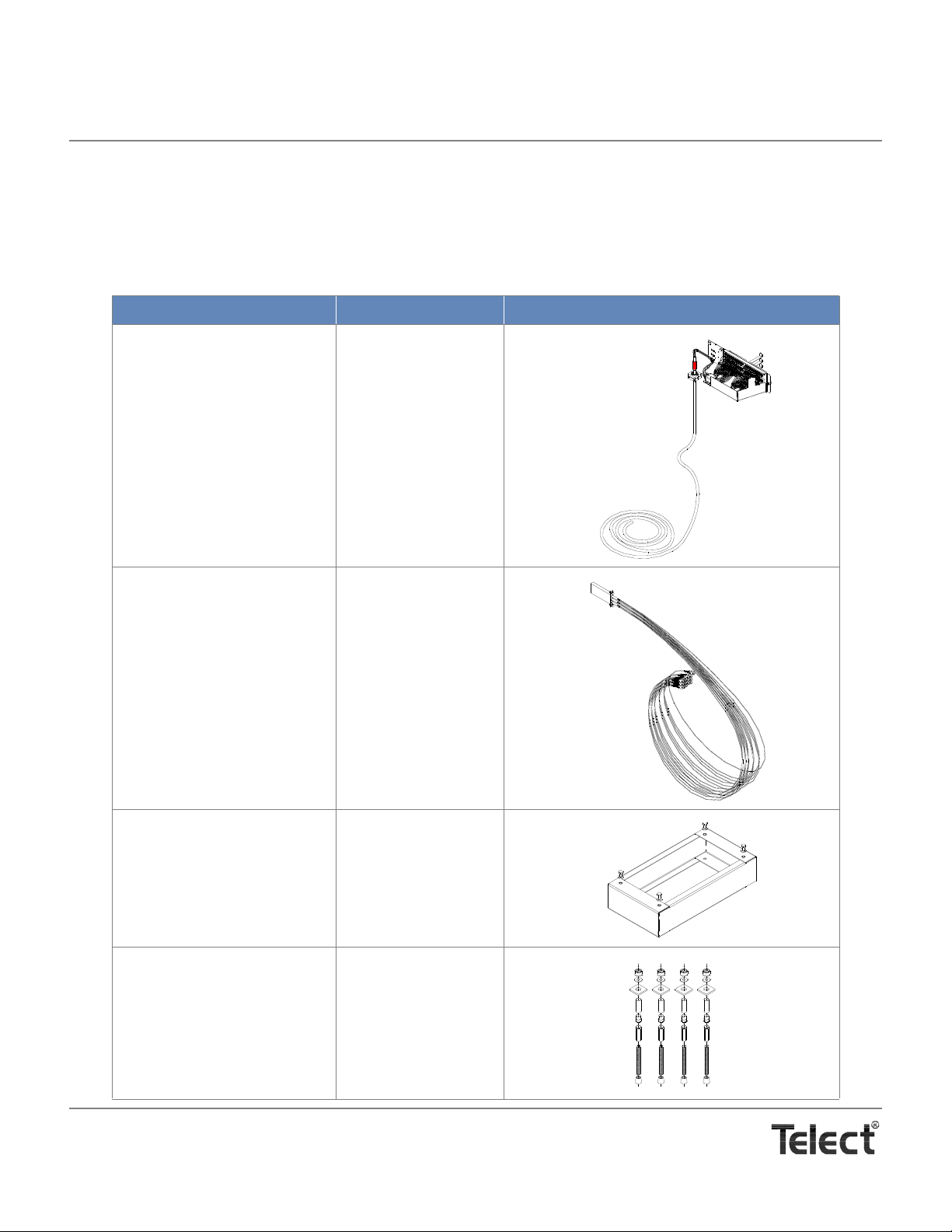
7. Accessories
MDC-CB accessories and replacement items are listed in the following table. Contact Telect for price and availability.
STANDARD ACCESSORIES
Item Model Illustration
72-Channel Patch Module Connected to 100 Ft of OSP Cabling*
(dry, flexible, unarmored cable
with 72, 250 µm strands fully
protected in subunits, along
with fan-out blocks, one cable
clamp and heat-shrink tubing)
* Custom cable lengths available.
Splitter Modules
1 x 4
1 x 8
1 x 16
1 x 32
MDC-P72N-F100D
MDC-SP-N04S
MDC-SP-N08S
MDC-SP-N16S
MDC-SP-N32S
Cabinet Base, 12 in. MDC-R12
Concrete Anchor Kit, 6 in.,
Seismic
Telect, Inc. • USA +1.509.926.6000 • Mexico +1.52.33.3836.3700
Poland +1.48.713.239.100 • UK +1.44.1489.889500 • www.telect.com
Copyright © 2002 Telect, Inc., All Rights Reserved • Telect Publication 131220 A0
MDC-CBAK
Page 46
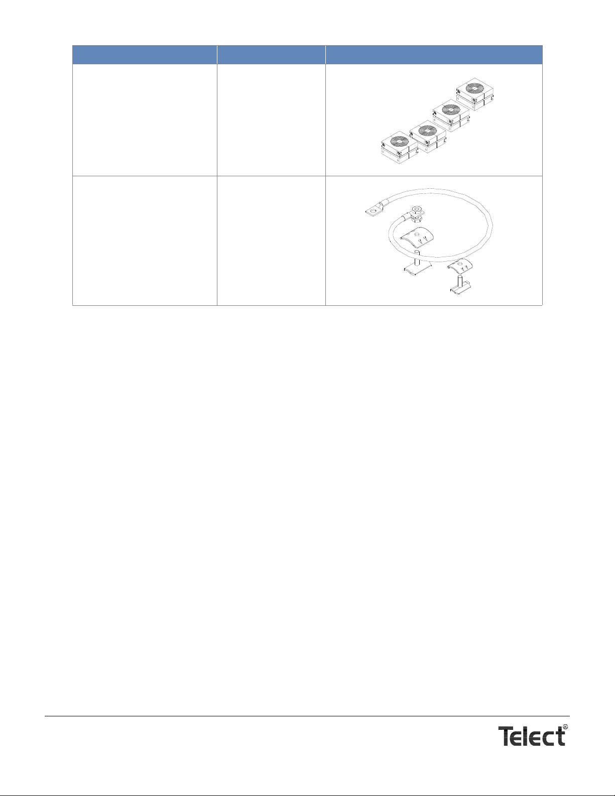
Item Model Illustration
Cable Entrance Clamp Kit
MDC-CLMP
(includes 4 clamps)
Ground Bonding Kit for Armored OSP Cable
1. Kit contains hardware for OSP armored cable from 0.5 in. (12.7 mm) to 1.6 in. (40.64). Kit also contains an 11 in. (~280
mm), 6 AWG ground wire assembly with single-hole lugs for #10 studs on both ends.
1
KIT-BOND
Telect, Inc. • USA +1.509.926.6000 • Mexico +1.52.33.3836.3700
Poland +1.48.713.239.100 • UK +1.44.1489.889500 • www.telect.com
Copyright © 2002 Telect, Inc., All Rights Reserved
Page 7-2
Page 47
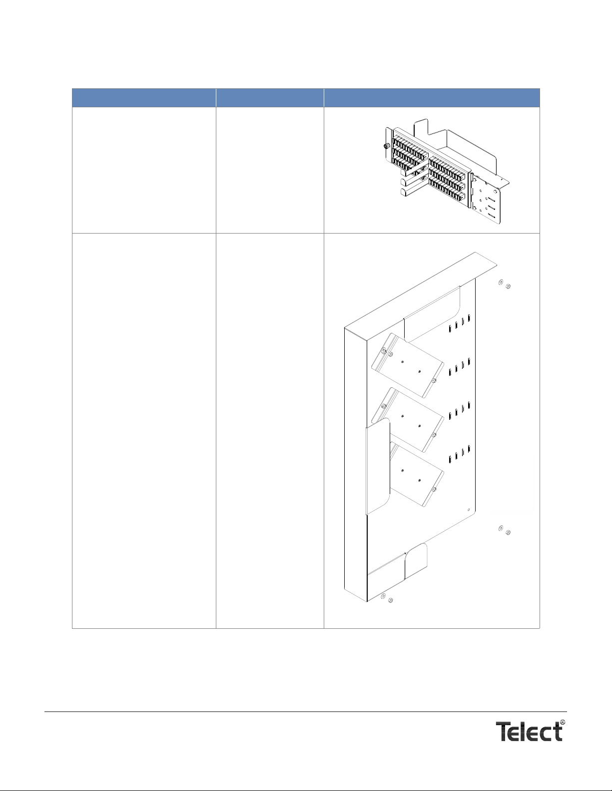
IN-CABINET SPLICING ACCESSORIES
Item Model Illustration
72-Channel Patch Module
Only*
(with dust covers in both ends
of SC/APC adapters; without
cabling, clamps, or fan-out
blocks
Splice Box* for In-Cabinet
Splicing
1
MDC-P72N
MDC-SPLC
Telect, Inc. • USA +1.509.926.6000 • Mexico +1.52.33.3836.3700
Poland +1.48.713.239.100 • UK +1.44.1489.889500 • www.telect.com
Copyright © 2002 Telect, Inc., All Rights Reserved
Page 7-3
Page 48
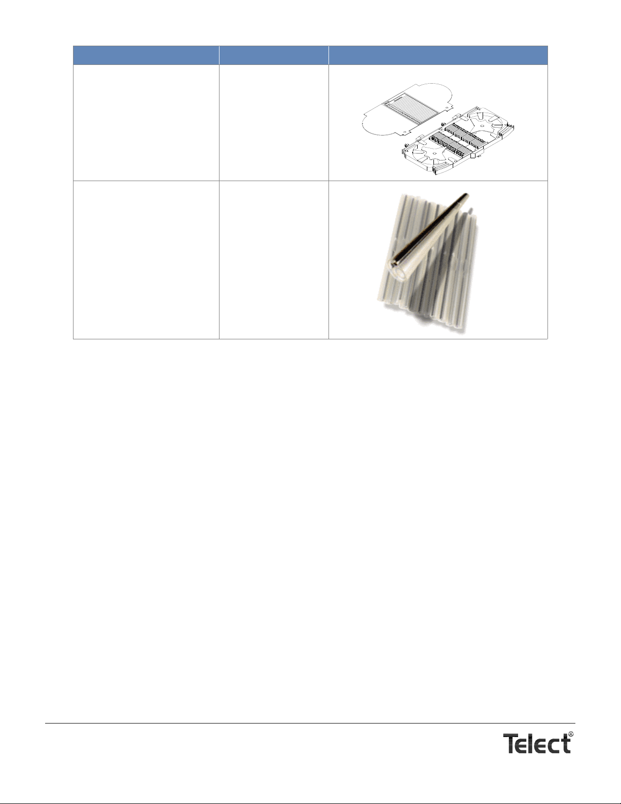
Item Model Illustration
Splice Cassette
MDC-HS24
(includes cassette label)
Splice Sleeves, Pkg of 12 101521-12
1. Installs on inside of rear door. Installation and routing of cable is different with in-cabinet splicing.
Telect, Inc. • USA +1.509.926.6000 • Mexico +1.52.33.3836.3700
Poland +1.48.713.239.100 • UK +1.44.1489.889500 • www.telect.com
Copyright © 2002 Telect, Inc., All Rights Reserved
Page 7-4
Page 49

Telect assumes no liability for the application or use of these products. Neither does Telect convey any license under its patent rights or the patent
rights of others. This document and the products described herein are subject to change without notice.
Telect, Inc. • USA +1.509.926.6000 • Mexico +1.52.33.3836.3700
Poland +1.48.713.239.100 • UK +1.44.1489.889500 • www.telect.com
Copyright © 2006 Telect, Inc., All Rights Reserved
Page 50

Telect, Inc. • USA +1.509.926.6000 • Mexico +1.52.33.3836.3700
Poland +1.48.713.239.100 • UK +1.44.1489.889500 • www.telect.com
Copyright © 2002 Telect, Inc., All Rights Reserved
 Loading...