

Page 1
®
®
MIX 56
USER MANUAL
122188-10 A0
Page 2

MIX 56 User Manual
Document Number 122188-10 A0
Copyright© 2001, Telect, Inc., All Rights Reserved.
Telect® and Connecting the Future® are registered trademarks of Telect, Inc., 1730 N. Madson St., Liberty Lake,
Washington 99019
Technical Support (USA):
By e-mail: [email protected]
By phone: 888-821-4856 or 509-921-6161
Note:
Telect assumes no liability from the application or use of these products. Neither does Telect convey any license under its patent rights nor the patent rights of others. This document and the products described herein are subject to
change without notice.
REGULATORY AGENCY COMPLIANCE
This equipment complies with the requirements in Part 15 of FCC Rules for a Class A computing device. Operation
of this equipment in a residential area may cause unacceptable interference to radio and television reception, requiring the operator to take whatever steps are necessary to correct the interference. T elect shielded cables should be used
with this unit to ensure compliance with the Class A limits.
This equipment is listed to UL 60950, Third Edition; EN60950:1992; EN55022, Class A, 1994; and EN50082-1,
1991 (EN61000-4-2, EN61000-4-3, EN61000-4-4), following the provisions of the EMC directive 89/336/EEC and
the Low Voltage directive 73/23/EEC.
WARRANTY AND LIABILITY
Limited Two Year Depot Warranty (Except Where Prohibited By Law)
All Telect, Inc. MIX 56
use for two years after the original purchase by the end user. The “purchase date” shall be assumed to be the latest of
the following:
• The date the product was shipped from Telect;
• The date indicated on the returned warranty postcard, provided that the postcard is returned within 90 days of the
ship date; or
• The date indicated on a photocopy of a sales receipt from either Telect or an authorized Telect distributor.
T elect’ s responsibility is limited to depot repair, refurbishment, or replacement (at Telect’s discretion) of the defective
product with the same version or upgrade, or, if repair/refurbishment/replacement is not possible, a refund of the purchase price. Repair parts and replacement products will be provided on an exchange basis and will be either new or
reconditioned. This limited warranty does not cover damage to the product resulting from accident, disaster, misuse,
abuse, negligence, improper maintenance, or modification or repair by other than Telect personnel.
Limited warranty service may be obtained by contacting Telect’s technical support department at 800-551-4567. NO
DEPOT WARRANTY SERVICE WILL BE PROVIDED UNLESS A RETURN MATERIAL AUTHORIZATION
(RMA) NUMBER HAS BEEN ISSUED AND THE PRODUCT IS SHIPPED WITH AN ENCLOSED REPAIR/REPLACEMENT CARD. This limited warranty is in lieu of all other warranties, expressed or implied, including, but
not limited to, the implied warranties of merchantability and fitness for a particular purpose. Some countries do not
allow the exclusion of implied warranties, and in such a case, the above exclusion may not apply to you.
TM
products are warranted to be free of defects in material and workmanship under normal
ii Telect, Inc. 122188-10 A0
Page 3

Out-of-Warranty Repairs
If the product warranty has expired or if the product does not qualify for warranty service, you will be charged a service fee. Out-of-warranty service will be performed only after receipt of payment. Please call the Telect, Inc. sales department at 800.551.4567 to inquire about current charges. NO SERVICE WILL BE PROVIDED UNLESS A RETURN MATERIAL AUTHORIZATION (RMA) NUMBER HAS BEEN ISSUED.
Limitation of Liability
Neither Telect, Inc. nor their authorized distributors/dealers shall be liable for any defect, indirect, incidental, special
or consequential damages, whether in an action in contract or tort (including negligence and strict liability), such as,
but not limited to, loss of anticipated profits or benefits resulting from the use of the product or any breach of any
warranty, even if Telect or its authorized distributors/dealers have been advised of the possibility of such damages. In
no event will Telect or their authorized distributors/dealers’ liability exceed the price paid for this MIX 56 product.
Some countries do not allow the exclusion or limitation of incidental or consequential damages, and in such a case,
the above limitation may not apply to you.
SOFTWARE LICENSE AGREEMENT
This Software License Agreement (“Agreement”) between Telect, Inc. (“Telect”) and Licensee (“Licensee”) hereby
grants to Licensee a nontransferable, nonexclusive license to use the software incorporated with the Telect MIX 56
M13 Multiplexer/X-Connect system (“Product”) identified above, including the computer software and any associated media and printed materials (“Software”) for its internal business purposes subject to the following terms, conditions, and restrictions:
1. License
a. The license granted herein authorizes the Licensee, its authorized employees and any agents or contractors using
the Software in the performance of service for Licensee, to use the Software solely in conjunction with the operation
of the Product as specified in the Software documentation set forth in the Product user’s manual.
b. Neither the Software nor any part or portion thereof may be sublicensed, copied, reproduced or dup licated by any
means, or translated into machine language, without the prior express written permission of Telect, except that Licensee may make those copies of the Software necessary for nonproductive back-up purposes only. Further, Licensee
shall not compile, decompile, or reverse engineer the Software nor use the Software to develop derivative works or
commercially competitive products. Any attempts to do so shall be a breach of this Agreement.
c. Except as set forth in Section 1, use of or access to the Software in any manner by any person not employed by, or
under written contract with the Licensee is prohibited.
d. The right of the Licensee to use the Software under the terms of this Agreement shall commence on the date of purchase of Product by Licensee and shall continue perpetually, provided Licensee complies with the terms and conditions of this Agreement.
2. Title
The Software, enhancements, revisions, updates, upgrades, modifications, and derivative works thereto, custom programming, and all other items delivered by Telect under this Agreement, and all copyright, patent, and other intellectual property rights therein: (i) are owned or licensed by and are proprietary to Telect or its licensors and (ii) constitute commercially valuable trade secrets of Telect or its licensors.
3. Warranty
Telect represents and warrants to Licensee that, during warranty period for Product, the Software will perform substantially in accordance with the accompanying documentation and further warrants that the media, as originally delivered, shall be free from defects in materials and workmanship.
122188-10 A0 Telect, Inc. iii
Page 4

Limitation of Warranty
a. Telect does not warrant that the Software will be uninterrupted or error-free in all circumstances. Licensee’s sole
and exclusive remedy for breach of the warranty is that Telect will make a reasonable effort to correct any documented nonconformity reported in writing to Telect during the Product warranty period.
b. T elect is not responsible for any defect or noncompliance Software documentation not reported during the Product
warranty period or any defect or noncompliance Software documentation after the Software has been modified without the consent of Telect, or otherwise misused, or damaged.
EXCEPT AS EXPRESSLY SET FORTH IN THIS SECTION, AND TO THE MAXIMUM EXTENT PERMITTED
BY APPLICABLE LAWS, TELECT SHALL HAVE NO LIABILITY TO LICENSEE OR ANY THIRD PARTY
FOR THE SOFTW ARE OR PROVISIONS OF OR FAILURE TO PROVIDE SUPPORT SERVICES UNDER THIS
AGREEMENT, INCLUDING ANY LIABILITY FOR NEGLIGENCE; TELECT MAKES AND LICENSEE RECEIVES NO WARRANTIES, EXPRESS, IMPLIED, STATUTORY, OR IN ANY OTHER PROVISION OF THIS
AGREEMENT OR IN ANY OTHER COMMUNICATION ; AND TELECT SPECIFICALLY DISCLAIMS ANY
WARRANTY OF MERCHANTABILITY, FITNESS FOR A PARTICULAR PURPOSE, TITLE AND NONINFRINGEMENT.
4. Protection of Proprietary Rights
Licensee acknowledges that the Software contains information that is proprietary to Telect or its licensors, and that all
such information is of a confidential trade secret nature. Licensee will take all necessary steps to protect such proprietary rights and to maintain the confidentiality thereof, and agrees not to disclose any information regarding the Software to any third party except Licensee’s employees, agents and contractors who have a need to know and who are
bound in writing to preserve the confidentiality thereof. Licensee agrees that its contractors shall have access to the
Software only at Licensee’s location. Licensee further agrees that its contractors shall be deemed agents of Licensee
and therefore Licensee shall have the same liability for its contractors as Licensee has for its employees and agents.
Licensee will promptly notify Telect of any unauthorized use of the Software. Each party’s obligations with respect to
confidentiality shall survive the termination of this Agreement. Each party’s confidential information shall not include information that: (a) is or becomes a part of the public domain through no act or omission of the other party; (b)
was in the other party’s lawful possession prior to the disclosure and had not been obtained by the other party either
directly or indirectly from the disclosing party; (c) is lawfully disclosed to the other party by a third party without restriction on disclosure; or (d) is independently developed by the other party without breaching any confidentiality obligations.
5. Limitation of Liability; Exclusion of Consequential Damages
The maximum cumulative liability of Telect to Licensee for all claims relating to the Software and any Services rendered hereunder, in warranty, contract, tort, or otherwise, shall not exceed the total amount of the price paid for Product by Licensee.
TO THE MAXIMUM EXTENT PERMITTED BY APPLICABLE LAW, IN NO EVENT, UNDER THIS SECTION
OR OTHERWISE, SHALL TELECT BE LIABLE TO LICENSEE FOR ANY SPECIAL, INCIDENTAL, INDIRECT, OR CONSEQUENTIAL DAMAGES WHATSOEVER (INCLUDING WITHOUT LIMITATION, DAMAGES FOR LOSS OF BUSINESS PROFITS, BUSINESS INTERRUPTION, LOSS OF BUSINESS INFORMATION,
OR ANY OTHER PECUNIARY LOSS) ARISING OUT OF USE OF OR INABILITY TO USE SOFTWARE OR
TELECT’S FAILURE TO PROVIDE SUPPORT SERVICES, EVEN IF TELECT HAS BEEN ADVISED OF THE
POSSIBILITY OF SUCH DAMAGES. THIS EXCLUSION AND LIMIT ATION OF LIABILITY APPLIES IN ALL
STATES/JURISDICTIONS WHERE PERMITTED BY LAW.
The foregoing limitation of liability and exclusion of certain damages shall apply regardless of the success or effectiveness of other remedies.
iv Telect, Inc. 122188-10 A0
Page 5

6. Indemnification
If a third party claims that the Software infringes any valid U.S. patent issued as of the effective date of this agreement or copyright, Telect will (as long as Licensee is not in default under this Agreement or any other agreement with
Telect) defend Licensee against such claim at Telect’s expense and pay all damages that a court finally awards, provided that (a) Licensee promptly notifies Telect in writing of the claim, and (b) allows Telect to cont rol, and cooperates with Telect in, the defense or any related settlement negotiations. If such a claim is made or appears possible,
T elect may, at its option, secure for Licensee the right to continue to use the Software, modify or replace the Software
so it is noninfringing, or, if neither of the foregoing options is reasonably available in Telect’s judgment, terminate
this Agreement and provide to Licensee a pro rata refund of the Product purchase price depreciated on a straight-line
basis over a five-year period. However, Telect has no obligation for any claim based on a modified version of the
Software or its combination, operation, or use with any product, data or apparatus not provided by Telect. THIS
PARAGRAPH STATES TELECT’S ENTIRE OBLIGATION TO LICENSEE AND LICENSEE’S SOLE AND EXCLUSIVE REMEDY WITH RESPECT TO ANY CLAIM OF INFRINGEMENT.
7. General
Assignment. Licensee may not assign this Agreement or any of its rights or obligations or sublease, sublicense or otherwise transfer the Software without Telect’s express prior written consent.
Severability. If any of the provisions of this Agreement shall be invalid or unenforceable, such invalidity or unenforceability shall not invalidate or render unenforceable the entire Agreement. The entire Agreement shall be construed as if not containing the particular invalid or unenforceable provision or provisions, and the rights and obligations of Telect and Licensee shall be construed and enforced accordingly.
Export Administration. Licensee agrees to comply fully with all applicable export laws and regulations of the United
States to assure that neither the Software nor any direct product thereof are (a) exported, directly or indirectly, in violation of export laws; or (b) intended to be used for any purposes prohibited by export laws.
Governing Law. This Agreement and any disputes or matters arising under, in connection with, or relating to this
Agreement shall be governed by and construed in accordance with the substantive laws of the United States and the
State of Washington, without giving effect to the principles of conflict or choice of law of such state.
Venue and Jurisdiction. The state and federal courts in the State of Washin gton shall have exclusive venue and jurisdiction for such disputes, and the parties hereby submit to personal jurisdiction in such courts.
Section Headings. The section headings used in this Agreement have been inserted for convenience only, and shall
not be deemed to limit or otherwise affect the construction of any provision hereof.
122188-10 A0 Telect, Inc. v
Page 6

vi Telect, Inc. 122188-10 A0
Page 7

1 Descriptions
MIX 56......................................................................................... 1-1
Features.................................................................................. 1-2
Part Numbers .........................................................................1-2
Main Assemblies.......................................................................... 1-3
Front Panel............................................................................. 1-3
LEDS ..................................................................................... 1-4
Rear Panel..............................................................................1-6
M13 Card............................................................................... 1-7
DSX Jack ............................................................................... 1-9
Specifications............................................................................. 1-10
Electrical.............................................................................. 1-10
Chassis Dimensions ............................................................ 1-11
Chassis Floor Weight (Fully Loaded).................................. 1-12
Environmental...................................................................... 1-12
Contents
2 Installation
Installation Considerations .......................................................... 2-1
Location and Space................................................................ 2-2
Tools and Equipment.............................................................2-3
Power ..................................................................................... 2-4
Technical Support (USA) ......................................................2-4
Inspection..................................................................................... 2-4
Installing MIX 56......................................................................... 2-5
Attaching the Mounting Brackets..........................................2-5
Rack-Mounting the Chassis...................................................2-6
Cabling a System ................................................................... 2-8
Cross-Connecting Circuits................................................... 2-12
Installing M13 Cards ........................................................... 2-13
Supplying Power.................................................................. 2-14
122188-10 A0 Telect, Inc. vii
Page 8

Installing The Optional RJ Connector Retrofit.......................... 2-15
Specifications....................................................................... 2-15
Schematic ............................................................................ 2-16
Installation Procedure .......................................................... 2-16
Connecting A Modem................................................................ 2-19
Disconnecting a Modem...................................................... 2-20
3 User Functions
The Alarm Cutoff/Lamp Button .................................................. 3-1
Disabling Alarms................................................................... 3-1
Testing LEDs and Resetting the ACO................................... 3-1
DSX Operation ............................................................................ 3-2
Patching Signals..................................................................... 3-2
Monitoring Signals ................................................................ 3-3
Modem Operation........................................................................3-4
4 Software Operation
Managing A System..................................................................... 4-1
Interfaces................................................................................ 4-2
Ports ....................................................................................... 4-2
To Connect With a Craft Interface Over the Craft Port......... 4-3
Craft Interface Basics................................................................... 4-4
Navigating Between Screens ................................................. 4-4
Navigating Within Screens.................................................... 4-5
Adding and Selecting Field Information ............................... 4-5
Getting Help........................................................................... 4-5
Default Software Configuration................................................... 4-6
Security Screen ..................................................................... 4-6
Save Configuration and Restore Configuration Screens .......4-7
System Settings Screen ......................................................... 4-7
High-Speed Configuration Screen ........................................4-7
Low-Speed Configuration Screen ......................................... 4-8
Alarm Thresholds Screen....................................................... 4-8
System Interfaces Screen ...................................................... 4-8
Accessing The Craft Interface .....................................................4-9
Setting Security...................................................................... 4-9
Managing Users................................................................... 4-10
Logging In............................................................................ 4-12
Logging Out......................................................................... 4-13
Configuring MIX 56.................................................................. 4-14
Specifying System Settings & M13 Card Functions ........... 4-14
Specifying System Interface Settings .................................. 4-17
Configuring the High-Speed Signal..................................... 4-19
viii Telect, Inc. 122188-10 A0
Page 9

Configuring the Low-Speed Channels................................. 4-21
Saving a Configuration........................................................ 4-26
Restoring a Configuration.................................................... 4-28
Viewing Errors........................................................................... 4-32
Viewing High-Speed Errors................................................. 4-32
Viewing Low-Speed Errors ................................................. 4-35
Managing Alarms And Events................................................... 4-39
Viewing Alarms................................................................... 4-40
Setting Alarm Thresholds.................................................... 4-42
Viewing Events.................................................................... 4-44
Performing Diagnostics ............................................................. 4-46
Running Loopbacks............................................................. 4-46
BER Testing............................................................................... 4-50
To Specify a BER Test ........................................................ 4-51
5 Owner Maintenance
Replacing DSX Jack Tracer Lamps............................................. 5-2
Replacing DSX Jacks................................................................... 5-3
Replacing M13 Cards .................................................................. 5-6
Replacing Alarm Cards................................................................ 5-8
Updating the Software ................................................................. 5-9
TFTP Update........................................................................ 5-10
Craft Port Update.................................................................5-12
Transferring Software Versions Between Cards ................. 5-14
6 Service
In Case Of Difficulty ................................................................... 6-1
In-Warranty Service..................................................................... 6-1
Out-Of-Warranty Service.............................................................6-1
Repacking For Shipment ............................................................. 6-2
Appendix A: Connector Pinouts
64-Pin Connector ....................................................................... A-1
DS1 In................................................................................... A-1
DS1 Out ............................................................................... A-2
RJ Connector Circuit Assignments............................................. A-2
Ethernet Connector ..................................................................... A-3
External Alarm Connector.......................................................... A-3
Power Connector......................................................................... A-4
Craft Port..................................................................................... A-4
Ground Switch............................................................................ A-4
122188-10 A0 Telect, Inc. ix
Page 10

x Telect, Inc. 122188-10 A0
Page 11

1 Descriptions
MIX 56
Telect’s Multiplexer with Integrated Cross-Connect, 56 Circuit (MIX 56)
chassis houses two fully independent systems, each with 28 DSX jacks and
up to two M13 multiplexer cards. Each system can be used as a DSX only,
as a nonredundant multiplexer, or as a redundant multiplexer.
When used as a DSX only, a system can be cabled quickly using the rear
64-pin connectors and provides full DSX functionality, including patching
and monitoring, using the DSX jacks on the chassis front.
When a single M13 card is added, a system becomes a nonredundant multiplexer/demultiplexer, which combines 28 DS1 or 21 E1 signals into a single industry standard DS3 signal and separates a DS3 signal into 28 DS1 or
21 E1 signals.
Adding a second card provides 1:1 redundancy for all M13 functionality.
The 28 DS1 low-speed channels and the DS3 high-speed interfaces reside
on one M13 card occupying one card slot, while the protection card occupies the second card slot. The two cards are in constant communication,
and all configuration changes made to the active card are also automatically made to the standby card.
Redundant and nonredundant multiplexer applications include full DSX
functionality when DS1 wiring is connected to the wire-wrap pins on the
front of the chassis, rather than to the rear 64-pin connectors.
Configuration, diagnostics, and performance monitoring are performed using SNMP through the Ethernet port, or using the Craft interface either remotely with T elnet through the Ethernet port or locally through the RS-232
Craft port.
122188-10 A0 Telect, Inc. 1-1
Page 12

1 Descriptions MIX 56 User Manual
Features
• DSX and M13 in one chassis
• Two fully independent systems per chassis, each with 28 DSX jacks
and up to two M13 cards, in a 5.25 inch (3 RU) rack space
• Mounts in 19 inch (48.3 cm) or 23 inch (58.4 cm) WECO-spaced or
EIA-spaced racks
• Multiplexes 28 DS1 or 21 E1 signals into one DS3 signal and demultiplexes a DS3 signal into 28 DS1 or 21 E1 signals
• 1:1 redundancy with second M13 card
• Processor switching occurs in less than 50 ms
• LED status indicators and tracer lamps on front panel
• DSX jacks, tracer lamps, and alarm boards are field replaceable and
M13 cards are hot-swappable, all from the front of the chassis
• Form-C critical, major, and minor external alarm contacts
• Remote provisioning and monitoring through SNMP or two concurrent
Telnet sessions
• Separate alarm and event logs are rotating logs of up to 99 entries each
• Selectable alarm thresholds
• DS1 and DS3 loopback capabilities
•BER Testing
• DS3 signal format selectable between C-bit or M13 mode
• C-Bit Remote Control to the MIX 56 at the other end of the DS3 link
• DS1 line coding individually selectable between AMI or B8ZS for T1
• Adjustable DS1 transmit line build out (LBO) for each channel
• Automatic DS3 LBO
• DS3 transmit clock source either recovered from DS3 receive signal or
• Universal voltages: 20Vdc to 60Vdc
• Three levels of user login security
Part Numbers
and AMI or HDB3 for E1
by internal oscillator
Part No. Configuration
747-0000-2448 56 DSX Jacks, No M13 Cards
747-1103-2801 56 DSX Jacks, Two M13 Cards
747-1103-5601 56 DSX Jacks, Four M13 Cards
1-2 Telect, Inc. 122188-10 A0
Page 13
MIX 56 User Manual 1 Descriptions
MAIN ASSEMBLIES
ALERT
!
ALERT! To avoid electrostatic discharge, always
wear a grounding strap plugged into the ESD jack
when handling any MIX 56 components.
Front Panel
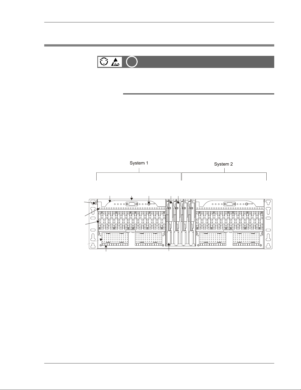
Each MIX 56 chassis houses two independent systems, System 1 and System 2. The front of each system is equipped identically (with the exception
of one electrostatic discharge (ESD) jack per chassis), and either system
can be used as a DSX only, as a nonredundant multiplexer, or as a redundant multiplexer.
ESD Jack
DSX
Tracer Lamp
DSX Jack
Wire-Wrap
Pin Field
ACO/LMP
CRT MJR MNR MAINT
Craft
Port
CRAFT
Button
HS LS ACO
23 25 2721191715131197531
LED
Panel
ESD
M13 Cards
(two for redundancy)
ESD
CRT MJR MNRMA INT
1
CRAFT
TL TL
TT
OUT
RR
TT
IN
RR
14 15
HS L S ACO
23 25 2721191715131197531
28
M13 Card Ejector HandleFanning Strip
Front View
(shown without doors)
Front Panel Definitions
ACO/LMP Button: One per system. When pressed and released, it turns
off external alarms for a time period specified in the system settings screen
of the Craft interface or through SNMP. When pressed and held for three
seconds, it tests the LEDs on the LED panel and the M13 cards by changing the panel LEDs to yellow (except Critical and Major, which turn to red)
and changing the card LEDs to orange. Testing the LEDs also resets the
ACO timer.
DSX Jack: 28 per system. Used for patching and monitoring DS1 signals.
122188-10 A0 Telect, Inc.
1-3
Page 14

1 Descriptions MIX 56 User Manual
DSX Tracer Lamp: One per DSX jack; used to locate cross-connects.
ESD Jack: One per chassis. Used when performing maintenance to pre-
vent harmful electrostatic discharge to electronic components.
Fanning Strip: One row per wire-wrap pin field. Used to properly dress
cross-connect wires.
M13 Cards: One or two per system. Houses the active circuitry for multi-
plexing functions. One card for nonredundant systems, two cards for redundant systems.
M13 Card Ejector Handle: One per M13 card. Used to remove and replace cards in the chassis.
Craft Port: One per system. Female DB-9, RS-232 serial connector used
to access the craft interface locally.
Wire-Wrap Pinfield: 28 DS1 pin fields per system. Used for routing and
cross-connecting DS1 signals. When using as a mux, Telect recommends
using these DS1 wire-wrap connections. This method of connecting the
low speed signals does not provide signal patching capabilities.
LEDS
NOTE
To use a system as a multiplexer with full DSX capabilities, connect incoming and outgoing DS1 signals to the front wire-wrap pins.
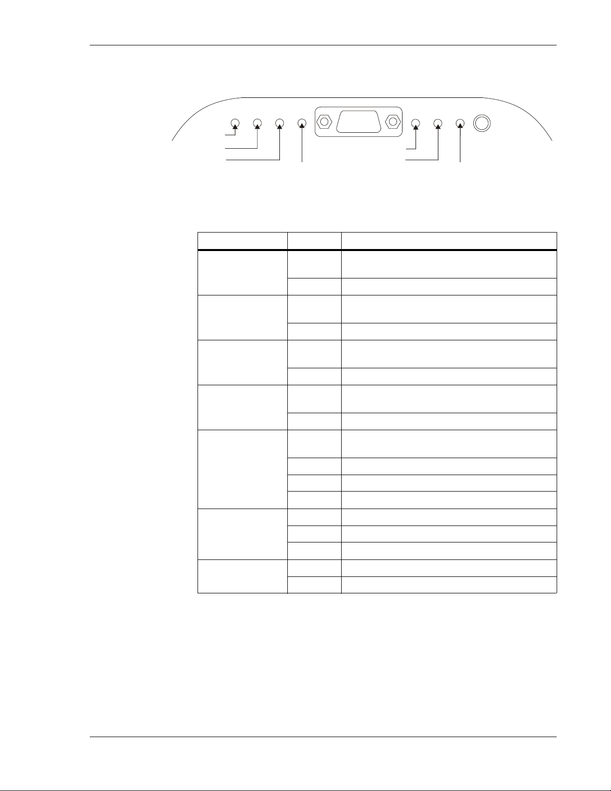
The LED status indicators on the MIX 56 front panel are grouped into the
following categories:
• DSX Tracer Lamps: When the tracer lamp (TL) pins of the cross-con-
nected modules are connected, the lamp lights when a plug is inserted
in the monitor port of one of the modules.
• M13 Card Status LED: One per card.
◊ Lights green for the active card.
◊ Lights orange for a standby card with no critical alarms.
◊ Solid red on the standby card indicates the card has detected a criti-
cal alarm condition or is otherwise nonoperational.
◊ Flashing red indicates a card cannot resolve an alarm condition.
◊ Unlit means the card is not receiving power, or has a failure in the
processor circuitry.
• LED Panel Indicators: See the next subsection.
1-4 Telect, Inc. 122188-10 A0
Page 15
MIX 56 User Manual 1 Descriptions
(
LED Panel
CRAFT
HS
LS ACO
ACO/LAMP
Alarm Cutoff
ACO)
Critical
Major
Minor
CRT MJR
MNR MAINT
Maintenance
High Speed
Low Speed
LED Status Definition
Critical
Major
Minor
Maintenance
High Speed
Low Speed
Red
Unlit No critical alarms
Red
Unlit No major alarms
Yellow
Unlit No minor alarms
Yellow
Unlit No diagnostic tests are being performed
Red
Yellow Receiving remote alarm indication (RAI)
Green Operating normally
Unlit Out of service or no power
Red Receiving AIS or experiencing LOS
Green Operating normally
One or more critical alarms. (Two or more DSIs and/
or DS3 service affecting conditions.)
One or more major alarms. (DS1 or DS3 service impacting condition.)
One or more minor alarms. Service processing and
traffic unaffected.
Diagnostic tests are being performed; at least one
circuit is out of service
Receiving alarm indication signal (AIS) or experiencing loss of signal (LOS) or out of frame (OOF) signal
Alarm Cutoff (ACO)
When a MIX 56 system used as a multiplexer is operating normally, the
High Speed and Low Speed LEDs on the LED panel and the active M13
card LED are all gr een. If the system is redundant, the standby card LED is
orange. Any LED configuration other than this indicates the system is not
operating normally.
122188-10 A0 Telect, Inc.
Unlit Out of service or no power
Yellow ACO is engaged
Unlit ACO is not engaged
NOTE
1-5
Page 16
1 Descriptions MIX 56 User Manual
Rear Panel
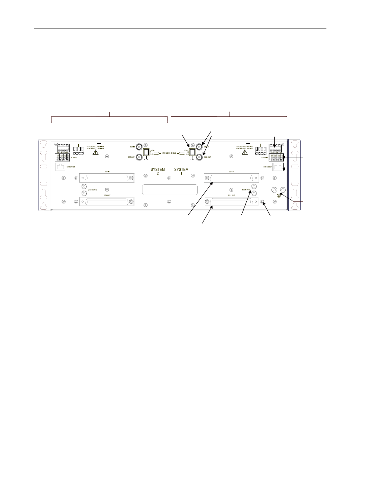
The rear of each system is equipped identically (with the exception of one
dual ground stud per chassis), and the connectors for each system are on
the opposite side of the chassis when facing the rear because the chassis is
divided into two independent systems.
System 2
Logic and Coax
Shield Ground
20-60V
+A
- A
- B
+B
Rear View
DS1 In
DS1 Out
System 1
DS3 In
DS3 Out
20-60V
Drain
Wire Studs
Receptacle
+B
- B
- A
+A
Power
Cable
Tie Lock
Alarm
Contacts
Ethernet
Port
Chassis
Ground
(one dual
stud per
chassis)
Rear Panel Definitions
Alarm Contacts: One set per system. Nine-contact, Phoenix-type connector. Form-C dry contacts used to extend critical, major , and mino r alarms to
alarm systems.
Cable Tie Locks: One per 64-pin connector, plus two in center of chassis,
for cable management.
Chassis Ground: One #10-32 dual ground stud per chassis.
Drain Wire Studs: Two per system, one for each 64-pin connector. #6-32
ground stud for attaching cable drain wire.
DS1 In: One per system. 64-pin female connector for incoming low-speed
signals when using system as a DSX.
DS1 Out: One per system. 64-pin female connector for outgoing low-
speed signals when using system as a DSX.
DS3 In: One per system. 75-ohm female BNC connector for incoming
high-speed signal.
DS3 Out: One per system. 75-ohm female BNC connector for outgoing
high-speed signal.
1-6 Telect, Inc. 122188-10 A0
Page 17
MIX 56 User Manual 1 Descriptions
Ethernet Port: One per system. RJ-45 10Base-T (half-duplex) connector
with two LEDs. Interface for managing system remotely via either SNMP
or Telnet. When lit, green LED means valid link pulse detected and flashing yellow LED means traffic in either direction.
NOTE
Before using the Ethernet port, you must connect to the local craft interface
through the Craft port and set the system’s IP and Subnet Mask addresses
in the System Interfaces screen. See “Specifying System Interface Settings”
on page 4-17.
Power Receptacle: One per system (20Vdc to 60Vdc). Four-position connector (14-22 A WG) used to supply re dundant (A, B) power to the system.
The power connector may be a wire-clamping, screw-type terminal or a
two-piece mated connector.
Logic and Coaxial Shield Ground: One per system. Three-position DIP
switch. Used to connect logic ground, DS3 shield TX ground, and DS3
shield RX ground to chassis ground:
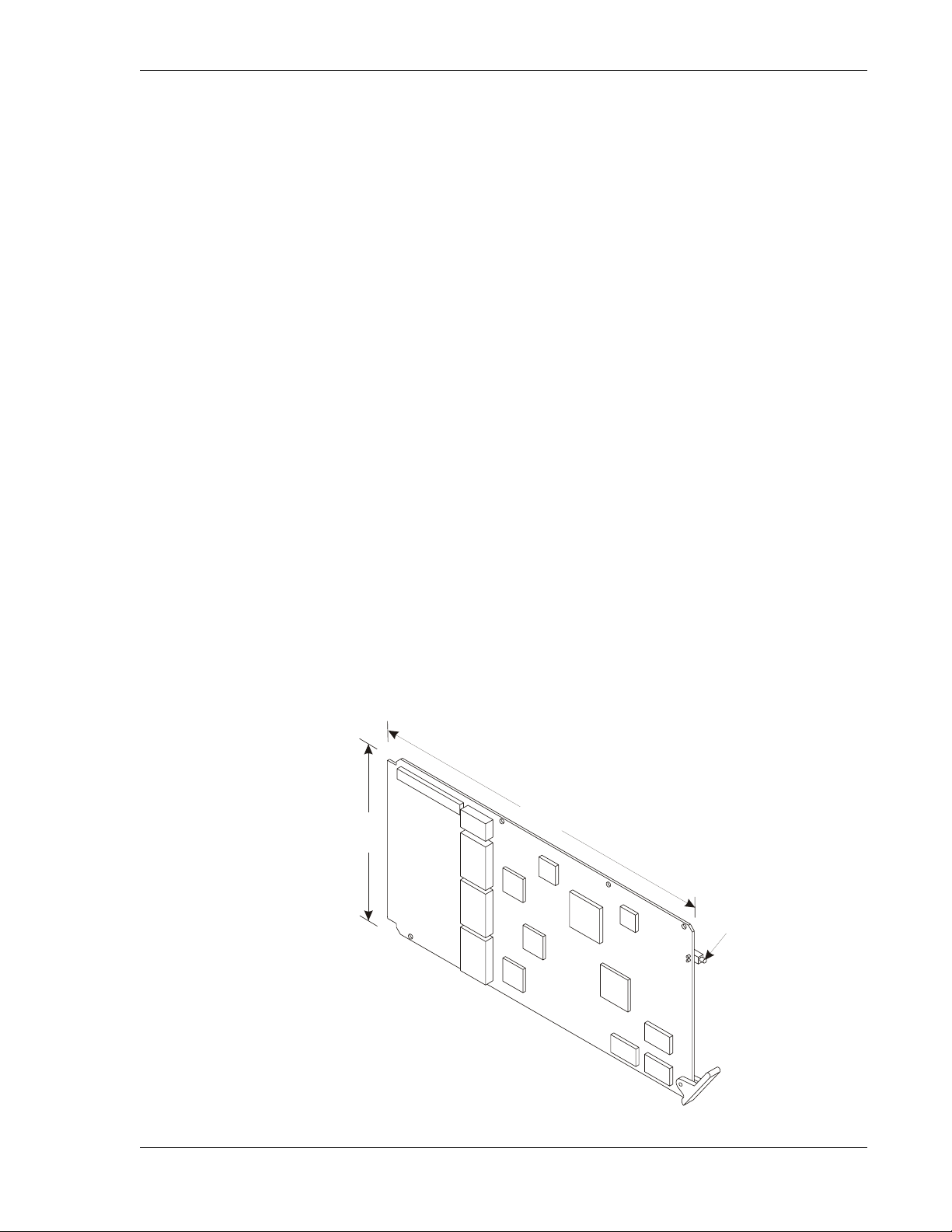
M13 Card
• on = connected to chassis ground
• off = disconnected from chassis ground
Dimensions
9.60 in.
4.75 in.
(12.07 cm)
(24.38 cm)
LED Status
Indicator
122188-10 A0 Telect, Inc.
Width = .06 in.
(.16 cm)
Part # 747-1001-0000
1-7
Page 18
1 Descriptions MIX 56 User Manual
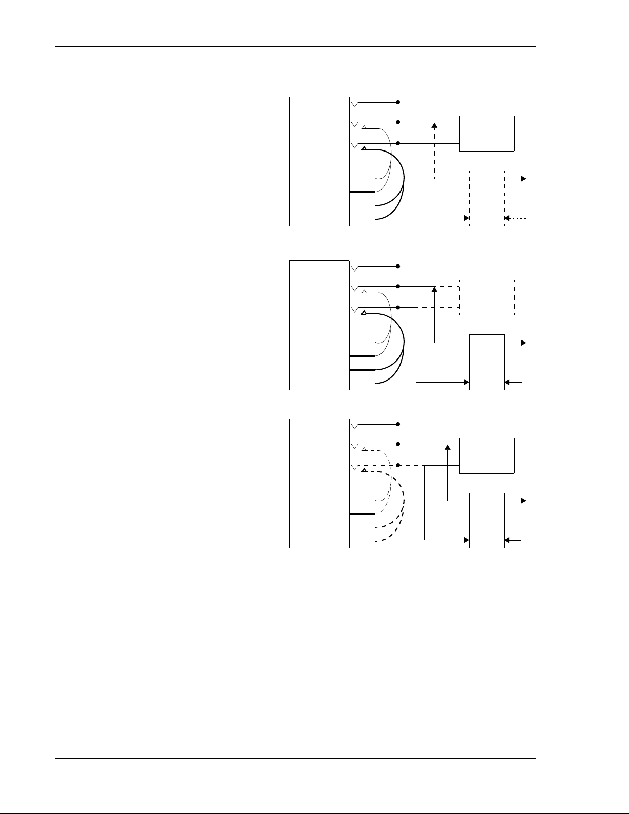
Signal Flow
MON
DSX Without M13
Amp connector cabled
to equipment.
Patch cord or wire-wrap
pins connect to another
DSX panel.
DSX With M13
Patch cord or wire-wrap
pins connect to another
DSX panel.
Low-speed signals are
multiplexed into highspeed.
Jacks
WW Pins
OUT
Jacks
WW Pins
OUT
OUT
IN
TL
IN
MON
OUT
IN
TL
IN
64-Pin Amp
T
R
T
R
T
R
T
R
Low
Speed
Low
Speed
M13
Mux
64-Pin Amp
M13
Mux
High
Speed
High
Speed
MON
OUT
IN
OUT
IN
TL
64-Pin Amp
T
R
T
R
Low
Speed
M13
Mux
M13 With Amp
Amp connector cabled
to equipment.
Low-speed signals are
multiplexed into highspeed.
* This method of connecting the low speed signals does not provide signal patching capabilities.
*
Jacks
WW Pins
High
Speed
1-8 Telect, Inc. 122188-10 A0
Page 19
MIX 56 User Manual 1 Descriptions
)
(
)
Jac
–
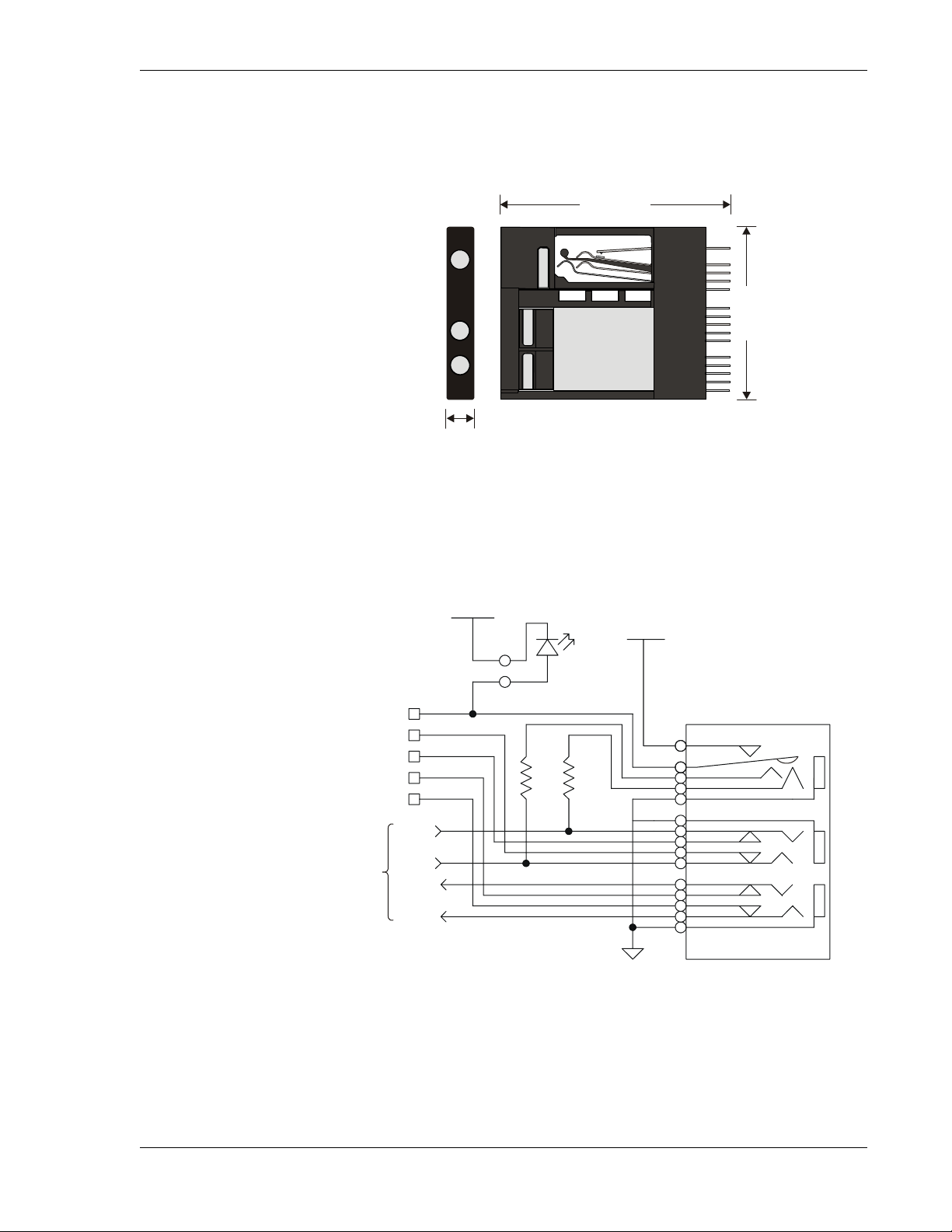
DSX Jack
Dimensions
2.09 in.
(5.30 cm)
M
Schematic
Wire-Wrap Pins
TL
T
R
T1
R1
O
I
.24 in.
.60 cm
1.58 in.
(4.00 cm
+
LED
1
R
R
Mon
R-n
To M13 & Backplane
T-n
T1-n
R1-n
SGND
15
k
122188-10 A0 Telect, Inc.
Out
In
1-9
Page 20

1 Descriptions MIX 56 User Manual
SPECIFICATIONS
Electrical
DS1
Impedance: 100 ohms nominal, balanced
Line Rate: 1.544 Mb/s ±32 ppm
Line Coding: AMI or B8ZS (user selectable)
Jitter: Meets ANSI T1.403, T1.102, AT&T 62411
Pulse Amplitude and Shape: Per ANSI T1.102, T1.403, and GR-342-
CORE
Return Loss: >26 dB
Short Haul DSX-1 (selectable)
Cable Length in feet (22 gauge ABAM or equivalent): 0–110, 1 10–220,
220–330, 330–440, 440–550, 550–660
Long Haul DS1 (selectable)
Cable Length (22 gauge ABAM or equivalent): 6000 ft (total cable
length).
Line Build Out (LBO): 0 dB, –7.5 dB, –15 dB, –22.5 dB. These correspond to approximate cable lengths of 6000-4500 ft, 4500-3000 ft,
3000-1500 ft, and 1500-0 ft, respectively. Receive sensitivity down to 30 dB. Far-end equipment must have comparable long-haul receive
sensitivity.
E1
Impedance: 120 ohms nominal, balanced
Line Rate: 2.048 Mb/s ±50 ppm
Line Coding: AMI or HDB3 (user selectable)
Jitter: Meets ITU-T G.703, G.823, and I.431
Pulse Amplitude and Shape: meets ITU-T G.703
Return Loss: >18 dB
DS3
Impedance: 75 ohms, unbalanced
Line Rate: 44.736 Mb/s ±20 ppm
1-10 Telect, Inc. 122188-10 A0
Page 21
MIX 56 User Manual 1 Descriptions
Line Coding: B3ZS
Jitter: Meets ANSI T1.102 and GR-342-CORE
Pulse Amplitude and Shape: Meets ANSI T1.102 and GR-342-CORE
Cable Transmit Length: 450 ft. to DSX using 734 coaxial type cable
Line Build Out (LBO): Adjusted automatically by system
Power
DC Input Voltage Range: 20Vdc to 60Vdc
DC Input Current: .75 amp max. at nominal –48Vdc per system; 1.5 amp
max.at nominal 24Vdc per systems
Wire Gauge: 18 AWG (recommended)
Fuse: 1A for nominal -48Vdc; 2A for nominal 24Vdc
Alarm Contacts
Form-C Contact Ratings: 400 mA at 125 Vac, 750 mA at 30 Vdc
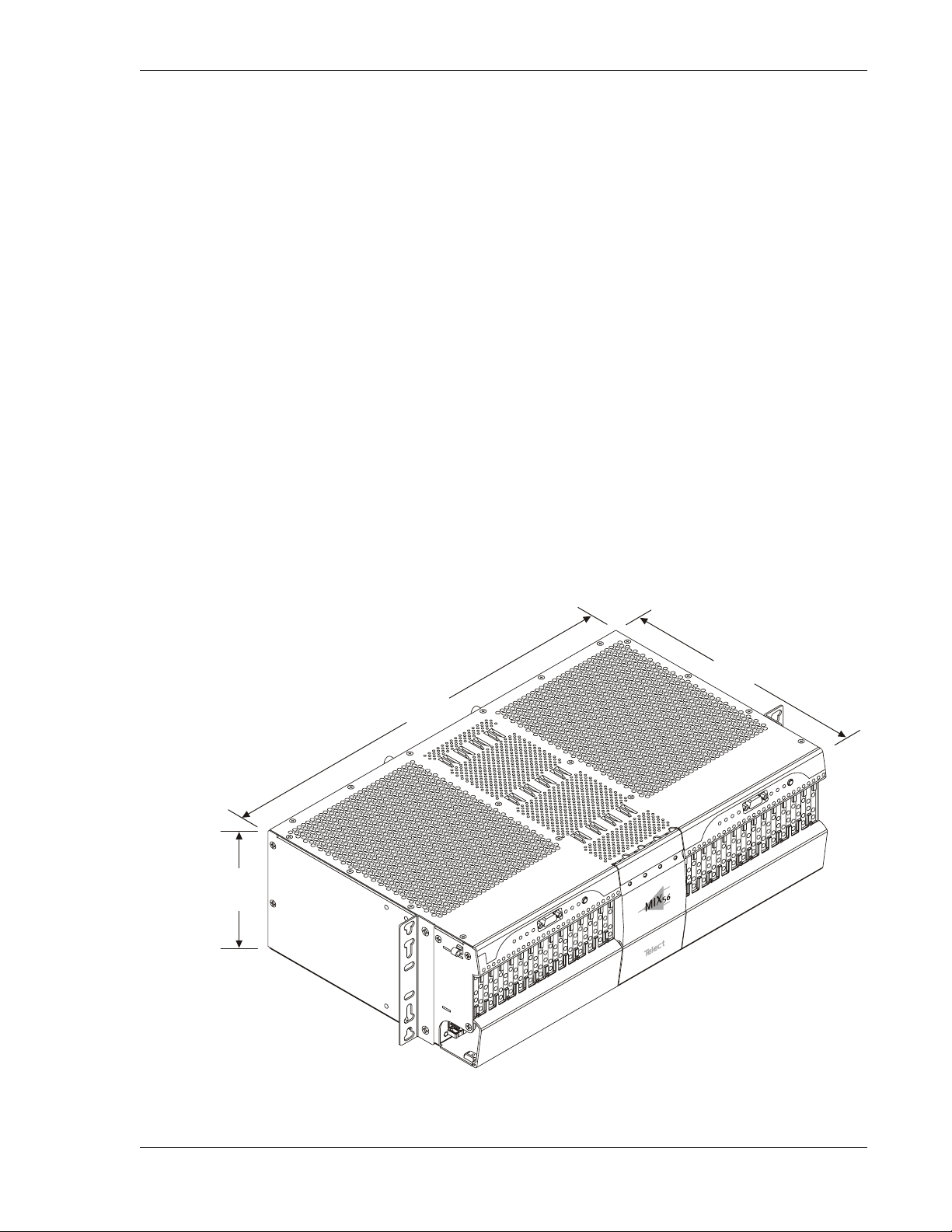
Chassis Dimensions
17.38 in.
(44.15 cm)
5.20 in.
(13.21 cm)
10.75 in.
(27.31 cm)
122188-10 A0 Telect, Inc.
1-11
Page 22

1 Descriptions MIX 56 User Manual
Chassis Floor Weight (Fully Loaded)
19 lb (8.7 kg)
Environmental
Operating Temperature: 0°C to +50°C
Nonoperating Temperature: –40°C to +65°C
Humidity: 5% to 95% noncondensing
Altitude: 0–10,000 ft. operating
Shock: Meets Telcordia GR-63 and NEBS level 3 requirements
Vibration: Meets Telcordia GR-63 and NEBS level 3 requirements
Heat Dissipation: 100 BTUs/hour (chassis with four M13 cards)
1-12 Telect, Inc. 122188-10 A0
Page 23
2 Installation
INSTALLATION CONSIDERATIONS
CAUTION
!
CAUTION! This product must be installed and maint ained only
by qualified technicians.
VORSICHT! Nur von qualifizierten T echnikern inst alliert werden
und instand gehalten werden.
PRECAUCIÓN! Ser instalado y ser mantenido solamente por
los técnicos autorizados.
ATTENTION! Ce produit doit être installé et entretenu uniquement par des techniciens qualifiés.
ALERT
!
ALERT! These instructions presume you have verified that this
Telect equipment being installed is compatible with the rest of
the system, including power, ground, circuit protection, signal
characteristics, equipment from other vendors, and local codes
or ordinances.
ALERT
ALERT! MIX 56 is not intended to be connected directly to outside plant (OSP) leads—install behind a listed NT1-type device.
122188-10 A0 Telect, Inc. 2-1
Page 24

2 Installation MIX 56 User Manual
Location and Space
ALERT
!
ALERT! This equipment is designed to permit connection of
the earthed conductor of the dc supply circuit to the earthing
conductor at the equipment. If this connect is made, all the following conditions must be met:
z This equipment shall be connected directly to the dc supply
system earthing electrode conductor or to a bonding jumper
from an earthing terminal bar or bus to which the dc supply
system earthing electrode conductor is connected.
z This equipment shall be located in the same immediate area
(such as adjacent cabinets) as any other equipment that has a
connection between the earthed conductor of the same dc supply circuit and the earthing conductor, and also the point of
earthing of the dc system. The dc system shall not be earthed
elsewhere.
z The dc supply source is to be located within the same pre-
mises as this equipment.
z Switching or disconnecting devices shall not be in the
earthed circuit conductor between the dc source and the point
of connection of the earthing electrode conductor.
The MIX 56 chassis mounts into standard 19- inch (48.3 cm) or 23-inch
(58.4 cm) WECO and EIA racks. A 23-inch rack installation requires the
extender bracket.
A single MIX 56 chassis requires 5.25 inches of vertical space (the height
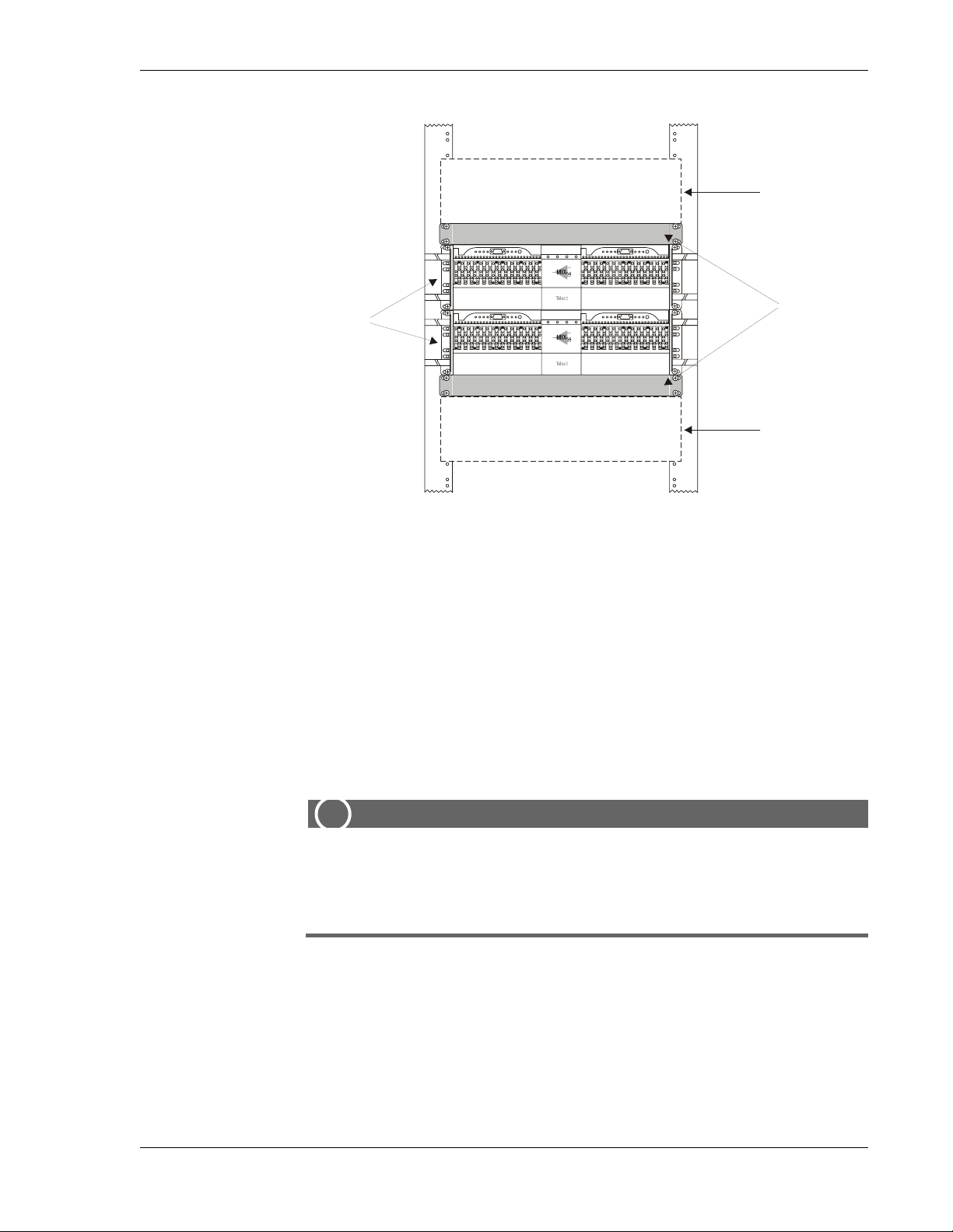
of the chassis). When installing one chassis on top of another , install a heat
baffle of at least one rack unit above and below the pair, as shown in the illustration on the next page. Telect recommends heat baffles below each
MIX 56: for a 19-in. rack, order part # 747-9999-0019; for a 23-in. rack,
order part # 747-9999-0023.
Heat Baffle
2-2 Telect, Inc. 122188-10 A0
Page 25
MIX 56 User Manual 2 Installation
t
MIX 56 or
Other Equipment
One-RU
Two MIX 56s, one
on top of the other
Heat Baffles
MIX 56 or
Other Equipmen
You can set the chassis to project 3, 4, or 5 inches from the front of the
rack, depending on which mounting bracket holes you choose. See “Attaching the Mounting Brackets” on page 2-5.
Computer Floor Issues
Each configuration varies in weight depending on the number and type of
chassis’ and cables used. If bay weight exceeds the floor support capacity,
computer floor supports can be ordered from T elect (part # 071-6000-3001/
3002 for one or two panels respectively).
Tools and Equipment
ALERT
!
ALERT! Only use crimping tools (such as Burndy Y8MRB-1 or
equivalent) and components approved by agencies or certifying bodies recognized in your country or region, such as Underwriter's Laboratories (UL), CSA, or CE.
You need the following tools to install MIX 56:
• Flathead screwdrivers: 3/16 to connect low speed cables; 3/32 to wire
power connector
• Phillips-head screwdrivers: #1 to remove M13 door, LED panel faceplates, and wire-wrap doors; #2 to attach mounting brackets to chassis
and attach chassis to rack
122188-10 A0 Telect, Inc.
2-3
Page 26
2 Installation MIX 56 User Manual
• 3/8 in. open-end or socket wrench to attach chassis ground wire to
ground stud
• Wire-wrap tool to attach front cross-connects when used as DSX or to
connect DS1 signals to M13 when used as multiplexer
Also, you must supply 14 AWG (minimum) insulated, stranded wire for
grounding, and a groundable shielded cable for the ethernet port.
Power
CAUTION
!
CAUTION! Do not supply power until all connections are made
in accordance with requirements specified in local electrical
codes.
ALERT
!
Technical Support (USA)
INSPECTION
ALERT! Protect this equipment with a listed/approved branch
circuit breaker sufficiently rated to interrupt power at either
–48 Vdc at 1 amp, or 24Vdc at 2 amp. The panel must be accessible when operating the unit.
The chassis must receive 20Vdc to 60Vdc. Since MIX 56 includes active
components, Telect recommends using a dual feed panel to provide input
power redundancy.
By e-mail: [email protected]
By phone: 888-821-4856 or 509-921-6161
Compare the contents of the MIX 56 shipping container with the packing
list. Call Telect if you are missing anything.
NOTE
Telect is not liable for shipping damage.
If the shipping container is damaged, keep it for the carrier’s inspection.
Notify the carrier and call Telect’s Customer Service Department:
2-4 Telect, Inc. 122188-10 A0
Page 27

MIX 56 User Manual 2 Installation
1-800-551-4567 or 1-509-926-6000
Keep the container until you have checked equipment operation. If you experience any kind of problem, call Telect’s Customer Service Department.
Use the original, undamaged container if you are instructed to return the
MIX 56 to Telect.
INSTALLING MIX 56
These procedures may be modified to agree with site practices or operating
company procedures.
NOTE
If you are installing the optional MIX 56 Broadband Sidecar
(PN 747-9999-2001), read the installation instructions included with the
kit before installing the MIX 56 chassis.
Attaching the Mounting Brackets
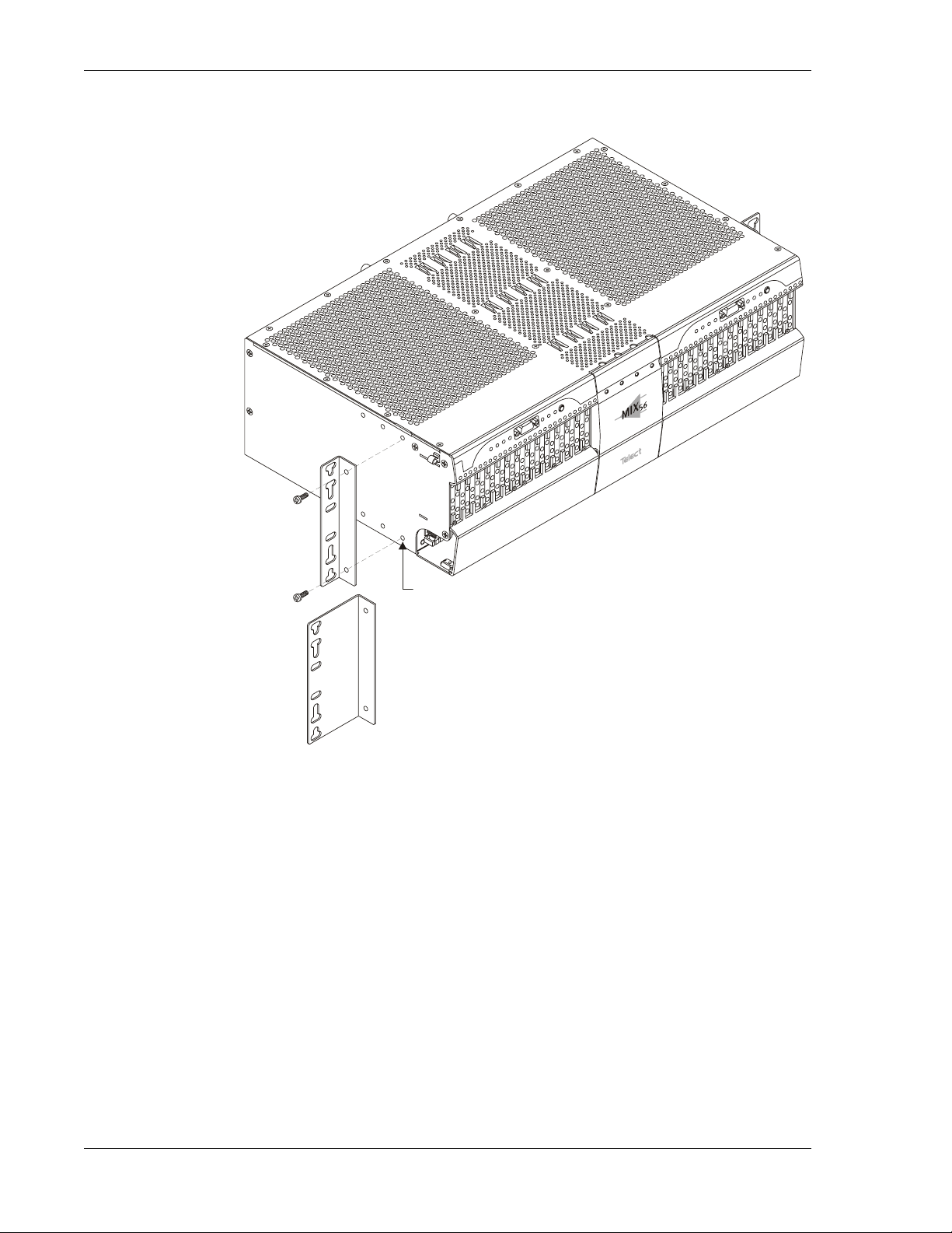
When attaching the mounting brackets, you can set the chassis to project 3,
4, or 5 inches from the front of the rack, depending on which set of holes
on the chassis you choose. The following illustration shows the standard
bracket being installed for 3-inch projection. To allow more front projection, use the middle set of holes for 4 inches or the last set of holes for 5
inches.
If you are mounting the chassis in a 23-inch rack, use the included extender
bracket shown in the illustration on the next page.
Step Action
1. Select the appropriate brackets (included) for the rack size, standard
for 19 in. racks or extender for 23 in. racks.
2. On one side of the chassis, insert two of the included #8-32 screws
through the bracket screw holes and into the bracket mounting
holes on the chassis, as shown in the illustration on the next page.
Choose holes that correspond to the desired front projection.
NOTE
122188-10 A0 Telect, Inc.
2-5
Page 28
2 Installation MIX 56 User Manual
Extender Bracket
3. Tighten the screws until the bracket is securely attached.
4. Repeat steps 2 and 3 on the other side of the chassis.
Rack-Mounting the Chassis
A single MIX 56 chassis requires 5.25 in. of vertical space (the height of
the chassis). When installing one chassis on top of another, install a heat
baffle of at least one rack unit above and below the pair. See “Location and
Space” on page 2-2 for an illustration.
For 3-inch Projection
NOTE
Be sure the mounting brackets attached to the chassis are appropriate for
the size of the rack. See “Attaching the Mounting Brackets” on page 2-5.
2-6 Telect, Inc. 122188-10 A0
Page 29
MIX 56 User Manual 2 Installation
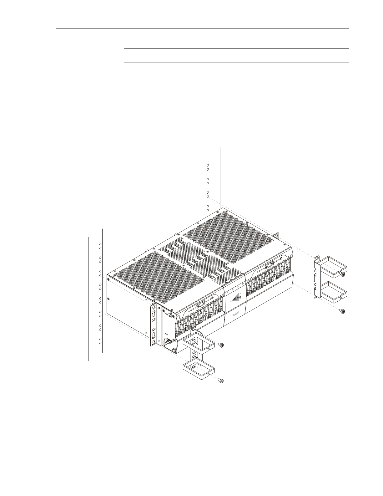
Step Action
1. Loosely mount the chassis to the rack using the four #12-24 screws
(included).
2. On one side of the chassis, insert a wire management ring (included) between the chassis mounting bracket and the head of the
screw, as shown below, and tighten the screws tight enough to hold
the ring in place.
3. Repeat step 2 on the other side of the chassis.
122188-10 A0 Telect, Inc.
2-7
Page 30
2 Installation MIX 56 User Manual
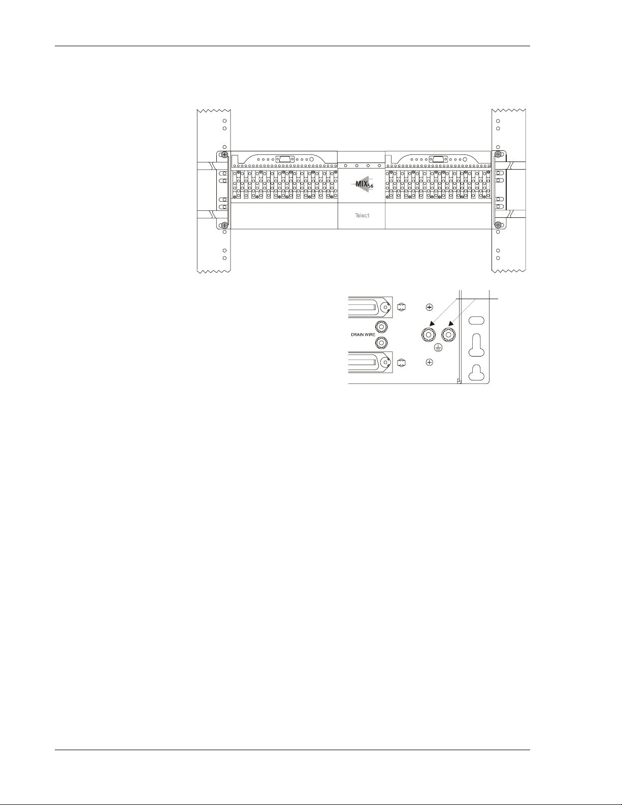
4. Tighten all four screws until the chassis and rings are securely attached to the rack
5. Ground the rear of the
chassis to the rack by attaching the supplied twohole lug using 14 AWG
(minimum) insulated,
stranded wire to the dual
ground stud shown below .
Cabling a System
The MIX 56 chassis contains two independent systems that each require
cabling. Telect recommends routing cables to the side of the chassis the
system is on, not crossing the cables to the other side of the chassis.
The following instructions describe cabling one system. To cable the other
system, repeat these steps, but route cables so as to create a mirror effect
from the first system. If using as a DSX only, this requires using 64-pin
connectors on the other system that are the reverse orientation of those
used on the first system.
If you are using the system as a DSX only , route the DS1 signals to the rear
64-pin connectors. This method provides full DSX functionality , including
patching and monitoring, using the DSX jacks on the chassis front.
Dual
Ground
Stud
If you are using the system as a redundant or nonredundant multiplexer,
full DSX functionality is available when you route the DS1 signals through
the wire-wrap pinfields on the front of the chassis, rather than through the
rear 64-pin connectors. You can still use the system as a multiplexer when
DS1 signals are routed through the rear 64-pin connectors, but you will not
have patch-jack functionality.
2-8 Telect, Inc. 122188-10 A0
Page 31
MIX 56 User Manual 2 Installation
(
You need the following items to cable a system as a multiplexer with full
DSX functionality:
• 24 AWG cross-connect wire
• Two 75 ohm coax cables with BNC connectors (Telect recommends
90-degree connectors, as shown below)
• One RJ-45 Ethernet cable (shielded, groundable)
• Wire for connecting external alarms
• Straight-wired DB-9 RS-232 cable
The only items needed to cable a system as a DSX are two 64-pin male cables and two cable tie wraps.
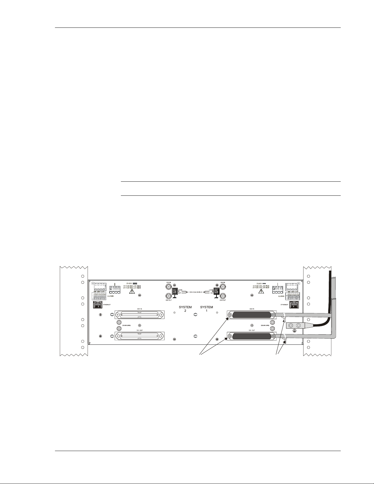
To Cable a System as a DSX
Step Action
1. Connect two 64-pin male cables to the two female connectors on
the rear of the chassis marked DS1 In and DS1 Out.
2. Tighten the two screws on each connector to secure the connectors
to the chassis.
3. Secure the cables to the chassis using tie wraps, as shown here:
–B+A–A
+B
64-Pin Connectors—
Tighten 1 screw each
shown here).
+B–B+A
–A
Tie Wraps
Prevent ground loops—check the site’s grounding practice standards.
Do not attach drain wires when using the system as a DSX. Only attach
drain wires when cabling the system as a multiplexer and connecting the
DS1 signals to the rear 64-pin connectors.
122188-10 A0 Telect, Inc.
NOTE
2-9
Page 32
2 Installation MIX 56 User Manual
To Cable a System as a Multiplexer
Step Action
1. Connect the DS1 signals to the wire-wrap
pins on the front of the chassis:
a. Connect 24 AWG cross-connect wire to
the pins.
b. Route the wire down through the fanning
Fanning Strip
strip and out.
c. Record designations on the label inside the wire-wrap door.
ALERT
ALERT! DO NOT connect the tracer lamp (TL) signal between
systems that operate on different supply voltages, such as between a +24Vdc system and a -48Vdc system. Industry
standard tracer lamp circuits are designed to operate with a
single system-wide voltage.
NOTE
If you prefer to connect the DS1 signals to the rear 64-pin connectors, see
“To Cable a System as a DSX” on page 2-9. This method of connecting the
low speed signals does not provide signal patching capabilities.
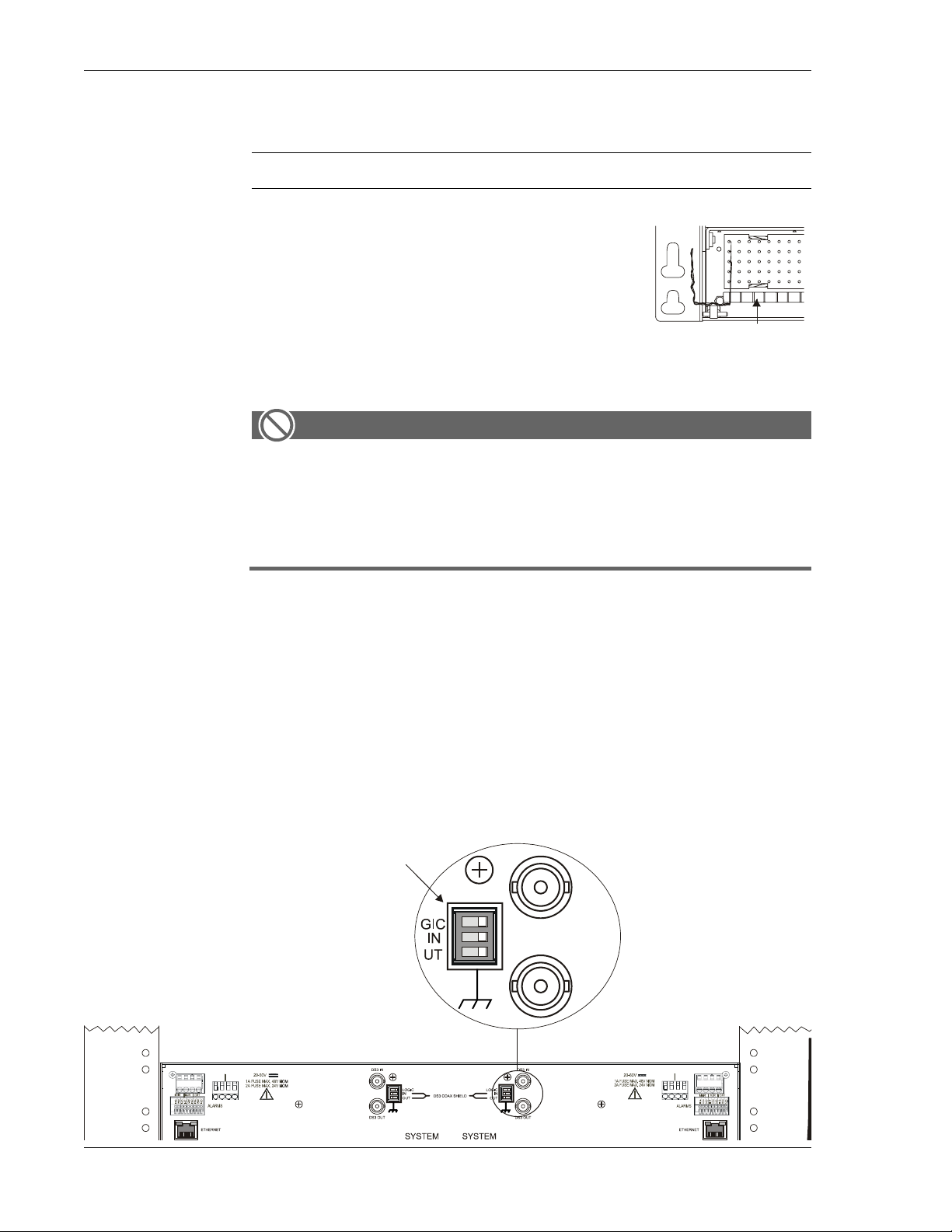
2. If your application requires changing the default Logic ground,
Coax Shield TX ground, and Coax Shield RX ground settings,
move the three DIP switch toggles to the desired position before installing the DS3 BNC connectors. See the table on the next page for
definitions of each toggle.
3-position
DIP Switch
O
1
n
2
3
–B+A–A
+B
+B–B+A
–A
2-10 Telect, Inc. 122188-10 A0
Page 33
MIX 56 User Manual 2 Installation
Type of Ground Switch Position Definition
Logic
(M13 Card Circuitry)
DS3 Coaxial Shield
Tx
DS3 Coaxial Shield
Rx
On (Default) Connected to chassis ground
Off Not connected to chassis ground
On (Default) Connected to chassis ground
Off Not connected to chassis ground
On (Default) Connected to chassis ground
Off Not connected to chassis ground
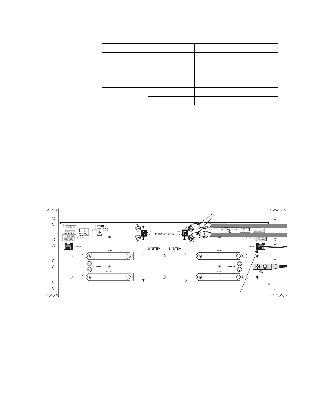
3. Connect two 75 ohm BNC cables to the connectors marked DS3 In
and DS3 Out, as shown below.
4. Connect an RJ-45 cable to the Ethernet port, as shown below.
NOTE
If you are connecting the MIX 56 to an Ethernet Hub, use a “straight”
Ethernet cable. If you are connecting directly to a Network Management
System (NMS) PC, use a “crossover” Ethernet cable.
Configure the network port as half duplex to match the MIX 56 Ethernet
port.
+B
–B+A–A
75 ohm BNC
Connectors
+B–B+A
–A
RJ-45 Ethernet Cable
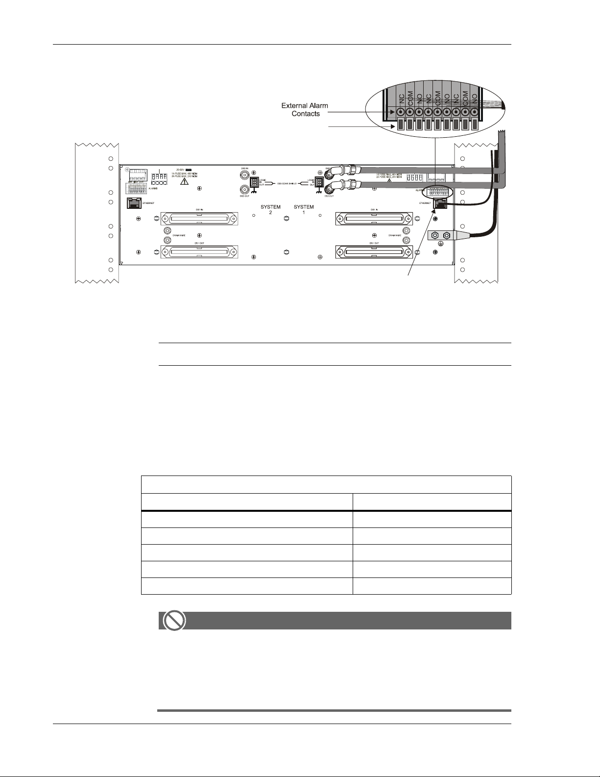
5. Connect external alarms to the Critical, Major, and Minor alarm
contacts by pressing and holding the spring clip, inserting the wire,
and then releasing the spring clip.
See the illustration on the next page.
122188-10 A0 Telect, Inc.
2-11
Page 34
2 Installation MIX 56 User Manual
Spring Clip
+B
–B+A–A
RJ-45 Ethernet Cable
+B–B+A
–A
Cross-Connecting Circuits
Step Action
1. Connect T and R (OUT) of first jack to T and R (IN) of second jack.
2. Connect T and R (IN) of first jack to T and R (OUT) of second jack.
3. Connect TL to TL (tracer lamps).
4. Record the cross-connect on the supplied designation strip.
Wire-Wrap Cross-Connect Color Scheme
Connect from 1st termination/wire color... ...To 2nd termination/wire color
TL / Green TL / Green
T (Out) / Blue T (Out) / Orange
R (Out) / Blue-White R (Out) / Orange-White
T (In) / Orange T (In) / Blue
R (In) / Orange-White R (In) / Blue-White
ALERT
ALERT! DO NOT connect the tracer lamp (TL) signal between
systems that operate on different supply voltages, such as between a +24Vdc system and a -48Vdc system. Industry
standard tracer lamp circuits are designed to operate with a
single system-wide voltage.
2-12 Telect, Inc. 122188-10 A0
Page 35

MIX 56 User Manual 2 Installation
Installing M13 Cards
ALERT
!
ALERT! To avoid electrostatic discharge, always
wear a grounding strap plugged into the ESD jack
when handling any MIX 56 components.
Step Action
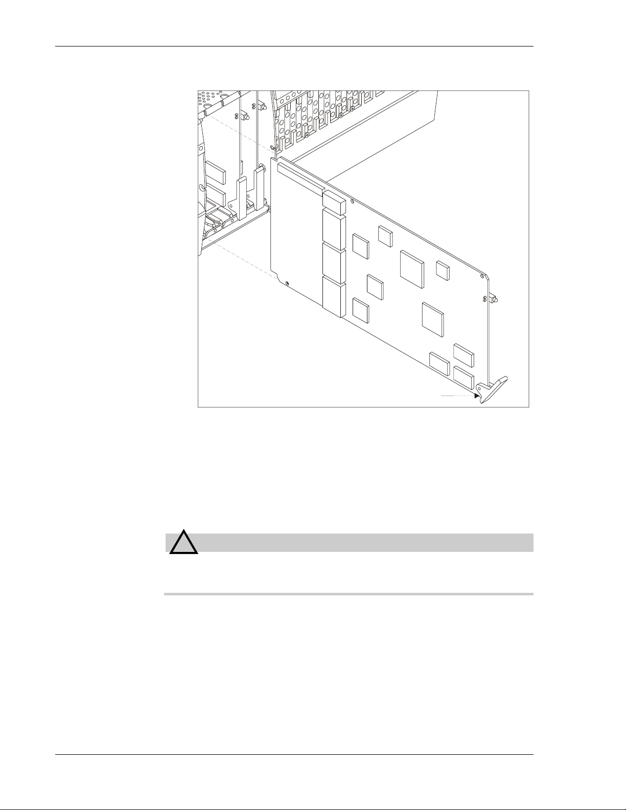
1. Open the card door and loosen the two captive screws (one per
side) holding the M13 card door in place. Remove the door:
2. Align the card with the card guides and gently insert it into the
122188-10 A0 Telect, Inc.
B
A
chassis by pressing the ejector handle against the card and pushing
the card back.
See the illustration on the next page.
2-13
Page 36
2 Installation MIX 56 User Manual
3. Replace the M13 card door by inserting the two screws into the
Supplying Power
!
CAUTION! Do not supply power until all connections are made
in accordance with requirements from local electrical codes.
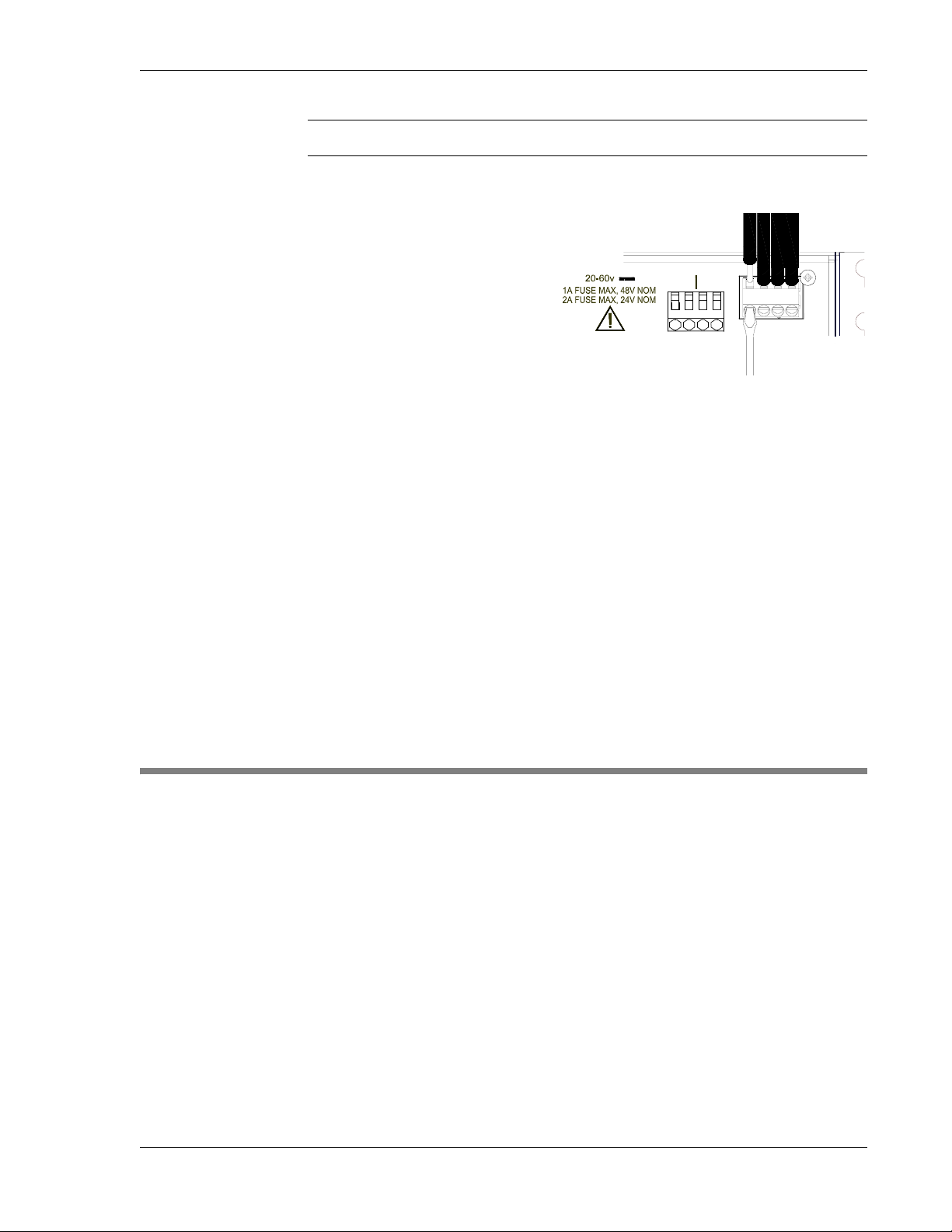
Each system has its own power receptacle that accepts the included fourposition, Phoenix-type connector to supply redundant power to the system.
Telect recommends a minimum of 18 AWG wire and either a 1A fuse at
nominal -48Vdc or a 2A fuse at nominal 24Vdc.
M13 Card
Ejector Handle
slots on the chassis and tightening them until the door is securely
attached to the chassis.
CAUTION
2-14 Telect, Inc. 122188-10 A0
Page 37
MIX 56 User Manual 2 Installation
Step Action
1. Verify the power source is unfused.
2. As instructed in the following paragraph, connect office battery and
–B
+B
–A
return (20Vdc to 60Vdc)
+A
to the screw-down wirebinding connectors labelled “A” at either toprear corners of the chassis. For example, for a
-48V dc plant, connect -48V to -A and RTN to +A; for a +24V
plant, connect +24V to +A and RTN to -A.
Loosen the set screws for each, insert the wires, and tighten the
screws.
3. To ensure power redundancy, repeat Step 2 for Side B using a separate power source. If you are not using a second source, connect
Side B to the same source as Side A to avoid triggering an alarm.
4. If a mating connector is used, insert the connector into the receptacle and tighten the two screws until the connector is securely in
place.
5. Fuse the power source to supply power to the chassis.
INSTALLING THE OPTIONAL RJ CONNECTOR RETROFIT
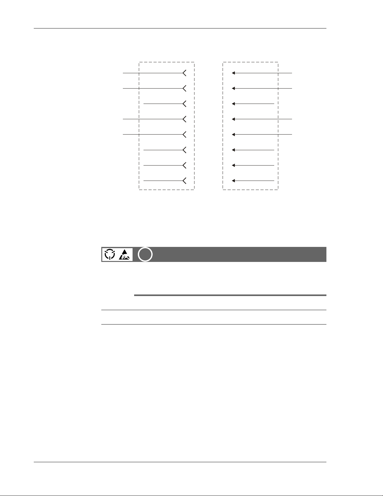
The optional RJ Connector Retrofit (part # 747-9999-2848) is a one piece
unit that converts a system’s wire-wrap pin blocks into 28 RJ-48 connectors. To install the unit, you must remove the wire-wrap door and its retainer clip, and install a mounting post on each side of the pin blocks, as described on the following pages.
Specifications
Universal Service Order Code (USOC): RJ-48C
Electrical Network Connection: Tip/Ring and Tip1/Ring 1
Mechanical Arrangement: 8-position miniature modular jack
Usage: 1.544 Mb/s digital access lines
122188-10 A0 Telect, Inc.
2-15
Page 38
2 Installation MIX 56 User Manual
t
Schematic
Signal out
of MIX 56
Signal into
MIX 56
R
T
R1
T1
Installation Procedure
1
2
3
4
5
6
7
8
Jack to Network
OUT
IN
Customer Installation
R1
Receive
T1
R
Transmi
T
Plug from
ALERT
!
ALERT! To avoid electrostatic discharge, always
wear a grounding strap plugged into the ESD jack
when handling any MIX 56 components.
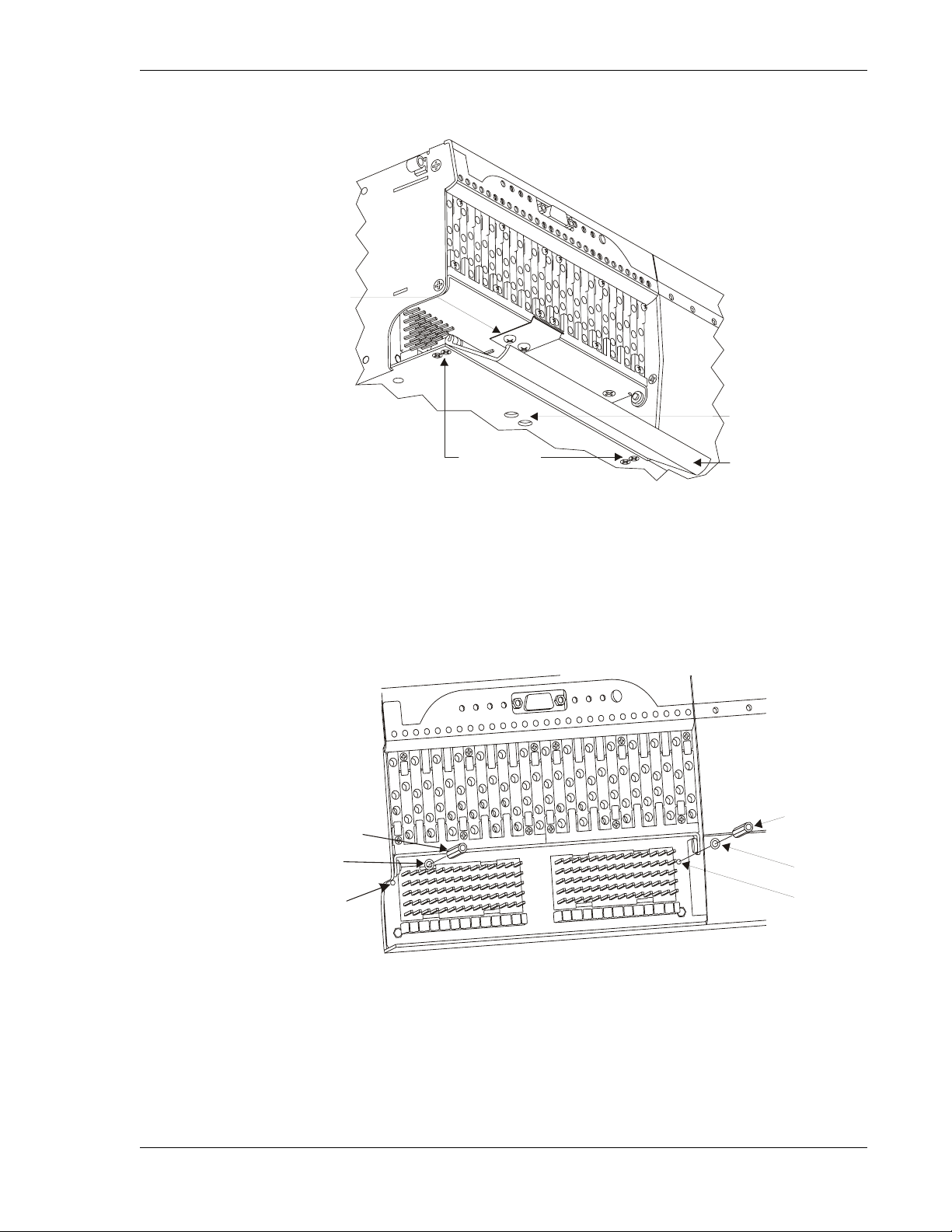
Step Action
1. Uninstall the wire-wrap door by removing the four hinge screws
shown below from the underside of the chassis.
2. Uninstall the door’s retainer clip by removing the two screws
shown in the illustration on the next page.
NOTE
If necessary, insert the screwdriver through the access holes from beneath
the chassis to remove the retainer clip screws.
2-16 Telect, Inc. 122188-10 A0
Page 39
MIX 56 User Manual 2 Installation
s
Retainer
Clip Screws
Retainer
Clip Screw
Access Hole
Hinge Screws
Door
3. Insert a mounting post through a washer and into a mounting post
hole on either side of the pin blocks, as shown below.
4. Using a 3/16 nut driver or a wrench, tighten the mounting post until
it is securely attached to the chassis.
5. Repeat Steps 3 and 4 on the other side of the pin blocks.
Mounting Post
Mounting Post
Washer
Mounting
Post Hole
Washer
Mounting
Post Hole
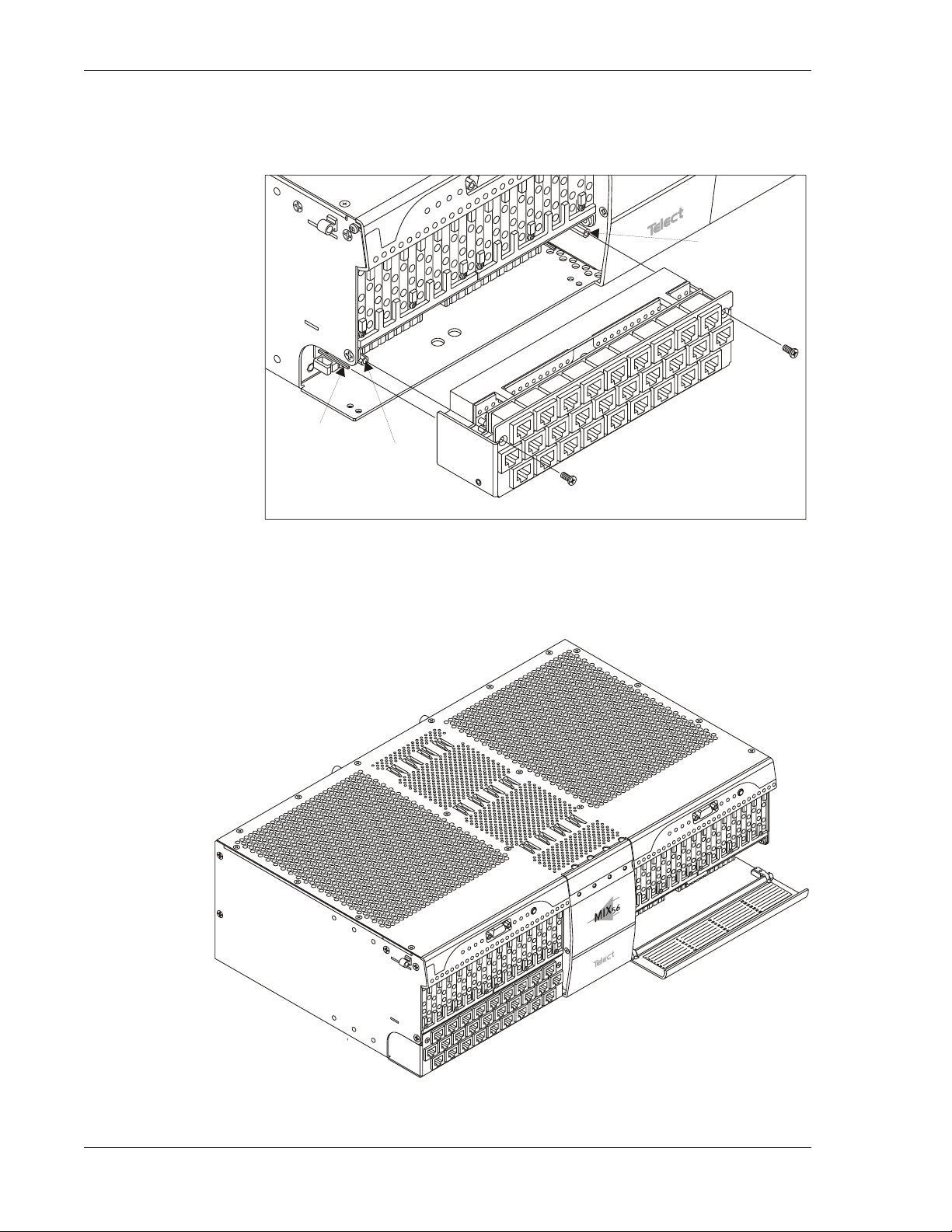
6. Gently place the holes on the back of the RJ Connector Retrofit
over the wire-wrap pins and carefully push the unit into place, as
122188-10 A0 Telect, Inc.
2-17
Page 40
2 Installation MIX 56 User Manual
shown below. Be sure each hole has a pin inserted in it. You may
need to gently wiggle the unit as you push it into place.
Mounting
Post
Wire-Wrap
Pin
Mounting
Post
7. Insert the two included screws through the RJ Connector Retrofit
and into the mounting posts, as shown in the previous illustration,
and tighten them until the unit is securely in place, as shown below.
2-18 Telect, Inc. 122188-10 A0
Page 41

MIX 56 User Manual 2 Installation
CONNECTING A MODEM
NOTE
Connecting a modem has the effect of disconnecting the local serial CID
interface. Serial CID control comes from a remote site through the modem
connection.
A modem will not work with the MIX 56 until the “Modem Detect” field
on the System Interfaces screen has been set to “Enabled.” See “To Set
Modem Detect” in the subsection, “Specifying System Interface Settings”
in Chapter 4 before beginning this procedure.
The MIX 56 modem automatically detects the baud rate at the MIX 56 serial port; there is no need to set or change the rate.
Step Action
1. Log in to the MIX 56. (See Chapter 4, “Logging In”.)
2. Access the System Interfaces screen and set the “Modem Detect”
field to “Enabled.”
3. Log out. (See Chapter 4, “Logging Out”.)
4. Set up the MIX 56 modem:
a. Connect the modem serial port to the MIX 56 serial port with a
null modem cable.
b. Connect the modem to a phone line.
c. Power up the modem.
5. Press and hold the ACO switch until the LED test starts (all LEDs
light), then release.
This causes an LED test and resets the ACO, as described on
page 3-1.
The MIX 56 modem is ready to communicate with a remote-site modem
when a remote modem calls in to establish a link. When the remote modem
establishes communication with the MIX 56, the user at the remote end can
log into the system. See Chapter 4, “Logging In.”
The login screen does not appear automatically at the remote site. Press the
Enter key at the remote site to access the login screen.
122188-10 A0 Telect, Inc.
2-19
Page 42

2 Installation MIX 56 User Manual
Disconnecting a Modem
Step Action
1. Log out at the remote modem.
2. Break the communication link by hanging up at the remote modem.
3. Disconnect the MIX 56 modem from the serial port.
4. Connect the MIX 56 serial port to the local PC.
5. Press and hold the ACO switch until the LED test starts, then release.
This causes an LED test and resets the ACO, as described on
page 3-1.
6. Login to the MIX 56.
7. Access the System Interfaces screen and set the “Modem Detect”
field to “Disabled.”
2-20 Telect, Inc. 122188-10 A0
Page 43

3 User Functions
(
THE ALARM CUTOFF/LAMP BUTTON
Each system has an Alarm Cutoff (ACO)/Lamp Button located on the LED
panel that disables the external alarm contacts and tests the LEDs.
Disabling Alarms
To disable the external alarm contacts, press and release the button marked
ACO/LMP.
The ACO LED lights and the alarms are disabled for the length of time
specified in the System Settings screen of the craft interface1 or through
SNMP.
CRAFT
LS
CRT MJR
MNR MAINT
HS
ACO
ACO/LAMP
Alarm Cutoff
ACO)
Alarm Cutoff/
Lamp Button
Testing LEDs and Resetting the ACO
As part of the LED test, the ACO is reset (the alarms are enabled). If the
alarms are disabled when you test the LEDs, you must disable them again
(see above) when the test is complete to return them to their previous state.
1. See “Specifying System Settings & M13 Card Functions” on page 4-14.
122188-10 A0 Telect, Inc. 3-1
Page 44

3 User Functions MIX 56 User Manual
Step Action
1. To test the LEDs, press and hold the button marked ACO/LMP for
three seconds:
• All LEDs on panel, except for Crt and Maj, change to yellow;
• Crt and Maj change to red;
• Active M13 card LEDs cycle between green and yellow at one
cycle per second; and
• The ACO resets.
2. To end the test and return the LEDs to their previous state, release
ACO/LMP.
3. If you need to disable the external alarms, press and release
ACO/LMP.
DSX OPERATION
When a MIX 56 system is used as a DSX only , with DS1 signals connected
to the rear 64-pin connectors, or as a multiplexer with DS1 signals connected to the front wire-wrap pins, you can perform all DSX functions including cross-connecting circuits with other network elements, rerouting traffic
with patch cords, and nonintrusive monitoring signals.
If the system is used as a multiplexer, but the DS1 signals are connected to
the rear 64-pin connectors, you cannot reroute traffic with patch cords.
Patching Signals
!
ALERT! When using a MIX 56 system as a multiplexer, you
must route DS1 signals to the front wire-wrap pins to be able to
patch signals.
NOTE
ALERT
If you need to perform network maintenance or emergency patch-arounds,
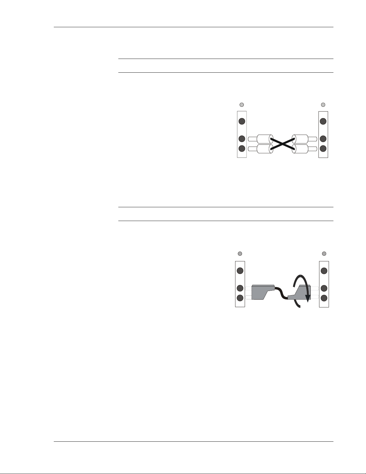
you can reroute incoming and outgoing lines by making temporary connections using either two single patch cords or a dual patch cord. Patching is
service-affecting, and the circuit is briefly interrupted while setting up and
taking down the patch.
3-2 Telect, Inc. 122188-10 A0
Page 45
MIX 56 User Manual 3 User Functions
d
d
To Patch with Two Single Patch Cords
Step Action
1. Insert a single patch cord into
the IN jack of the first jack.
2. Insert the other end into the
OUT jack of the second jack.
3. Insert another single patch
cord into the OUT jack of the
first jack.
4. Insert the other end of the
patch cord into the IN jack of
the second jack.
To Patch with a Dual Patch Cord
Step Action
1. Insert a dual patch cord into
the IN and OUT ports of the
first jack module.
First
jack
module
M
O
I
First
Jack
Module
Secon
jack
module
M
O
I
CROSS-CONNECT WITH
TWO SINGLE PATCH CORDS
Secon
Jack
Module
2. Rotate the plug on the other
end of the cord 180 degrees
(so that it is turned upside
down from the first end) and
insert it into the IN and OUT
ports of the second jack
module.
Monitoring Signals
You can perform nonintrusive signal monitoring by connecting your circuit
monitoring device to the front monitor jack (labeled M) of the signal you
wish to monitor.
M
O
I
CROSS-CONNECT
WITH DUAL PATCH CORD
M
O
I
122188-10 A0 Telect, Inc.
3-3
Page 46
3 User Functions MIX 56 User Manual
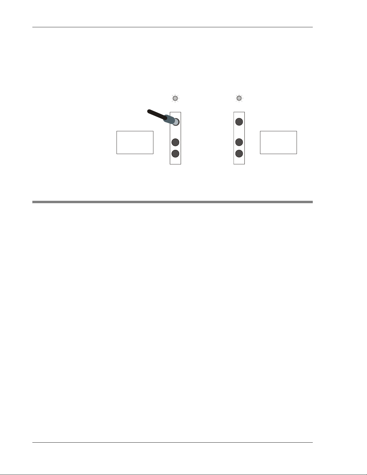
When you insert a plug into the monitor jack, the jack’ s LED flashes for 30
seconds, and then lights steadily . If the circuit is cross-connected, the crossconnected network element’s LED flashes and lights, as well.
MONITORING A NETWORK
ELEMENT’S OUTPUT SIGNAL
LED lights when monitored
Monitors output of
Network Element #1
MODEM OPERATION
You can connect a modem to the MIX 56 serial port to control the system
remotely over an analog phone line. To do so, you must set the “Modem
Detect” field on the System Interfaces screen to “Enabled” (Chapter 2) and
install the modem according to the instructions in Chapter 2. When you
have done so, activate the modem by pressing and holding the ACO switch
until all LEDs light (LED test), then release the switch.
NETWORK
ELEMENT #1
M
O
M
O
LED of the crossconnected network
element also lights
M
O
I
I
I
NETWORK
ELEMENT #2
(cross-connected to
Network Element #1)
If you set Modem Detect to “Enabled,” but you have a PC rather than a modem connected to the MIX 56 serial port, the modem detect code
“+++ATQ” appears on the screen at the current location of the cursor when
you release the ACO switch. To clear the “+++ATQ,” switch to another
MIX 56 screen.
The modem automatically detects baud rate at the MIX 56 serial port when
the modem is off-line. Once the modem is on-line, it will not change its
baud rate. If you change the MIX 56 baud rate (System Interfaces screen)
while the modem is on-line, you create a baud mismatch between the MIX
56 and modem, which shuts down the connection. The only way to regain
the connection is to “hang up” at the remote modem, press the ACO switch
until the LED test starts, release the switch, and reestablish the link from
the remote end.
To disconnect a modem, see the instructions in Chapter 2.
3-4 Telect, Inc. 122188-10 A0
Page 47

4 Software Operation
MANAGING A SYSTEM
You can configure, test, and monitor a system using these interfaces:
• Via Ethernet Port located on rear of chassis (one per system):
◊ SNMP (Simple Network Management Protocol) Interface
◊ Craft Interface over Telnet connection (up to two Telnet sessions)
◊ TL1 Interface over Telnet connection (up to two Telnet sessions)
• Via Craft Port (serial port) on front of chassis (one per system):
◊ Craft Interface over RS232 serial connection
◊ TL1 Interface over RS232 serial connection
• Via Remote Control:
If the MIX 56 is connected over the DS3 link to another MIX 56 and
they are both in C-bit mode on the DS3 link, then a remote control session can be run where the user is controlling the MIX 56 at the remote
end of the DS3 link.
◊ Craft Interface over DS3 Link
◊ TL1 Interface over DS3 Link
ALERT
!
ALERT! It is possible to have multiple active sessions at the
same time involved in configuring the same system. It is possible to have five active sessions at the same time: one via the
serial port; two via Telnet connections; one SNMP; and one via
Remote Control.
122188-10 A0 Telect, Inc. 4-1
Page 48

4 Software Operation MIX 56 User Manual
Interfaces
SNMP Interface
Telect provides a private enterprise MIB (management information base)
with which you can perform all MIX 56 functions. Telect’s private enterprise MIB also supports many features of the standard RFC 1213 MIB II.
You can download the latest MIB at www.telect.com.
You can use any SNMP-compatible network management system such as
SunConnect’s SunNet Manager, HP Open View, or Castle Rock’s SNMPc
to manage a system.
SNMP is available only over the Ethernet port.
Craft Interface
The Craft interface is a menu-driven system that can be accessed either by
the Craft (serial, RS232) port or Ethernet port. The Craft interface is covered in detail in this section of this manual.
Ports
TL1 Interface
The TL1 interface is a command line system that can be accessed either by
the Craft (serial, RS232) port or the Ethernet port. The TL1 interface is
covered in TL1 Design, Telect document 126055, included with the
MIX 56 System Software.
Craft Port
The Craft port is a nine-pin (DB9) RS-232 serial port located on the front
of the chassis that connects to an RS-232 terminal or a PC running terminal
emulation software in VT-100 mode. The terminal or PC port must be set
for 8 data bits, 1 stop bit, no parity; and its baud rate must match the Craft
port’s setting of the MIX 56. Craft port baud rate choices are 9600, 19200,
38400, 57600, or 115200. (The baud rate can be set from the Craft interface’s System Interfaces screen or the TL1 command “set-baud”.)
Use a shielded, straight wire RS-232 cable (not null modem cable) with a
male DB9 connector to connect to the Craft port.
Ethernet Port
The Ethernet port is a 10Base-T port that is located on the rear of the chassis. Configure your network port as half duplex to match the MIX 56 Ethernet port.
4-2 Telect, Inc. 122188-10 A0
Page 49

MIX 56 User Manual 4 Software Operation
NOTE
Before using the Ethernet port, you must connect over the Craft port and
set the system’s IP, Subnet Mask, and gateway addresses. This can be done
from the Craft interface’s System Interfaces screen or by the TL1 commands “set-ip-addr”, “set-subnet-mask”, and “set-gateway”. Remember
to set the Ethernet port to half-duplex. See “Specifying System Interface
Settings” on page 4-17.
To Connect With a Craft Interface Over the Craft Port
Step Action
1. If you are connecting to a PC, run terminal emulation software in
VT-100 mode.
2. Configure the terminal or PC port for 8 data bits, 1 stop bit, and no
parity.
3. Configure the terminal for the same baud rate as the MIX 56 is set
for in the System Interfaces screen. Choose between 9600 (default),
19200, 38400, 57600, or 115200 baud.
4. Connect the DB9 male end of the included cable to the DB9 female
port labeled “Craft” of the system (1 or 2) to which you are connecting.
5. Connect the other end of the cable to the RS232 terminal (or a PC
running terminal emulation software in VT-100 mode).
6. Press Enter.
The Directory screen, the Date and Time screen, or the Log In
screen appears, depending on your security setting and whether the
date and time has been entered since power up.
NOTE
The default security setting is Off.
122188-10 A0 Telect, Inc.
4-3
Page 50

4 Software Operation MIX 56 User Manual
CRAFT INTERFACE BASICS
Navigating Between Screens
You can move from the Directory screen to any other screen. The Directory
screen lists every screen of the Craft interface, grouped by function. Just
type the number of the screen you want to go to in the “Select Screen” field
and press Enter .
Step Action
1. To return to the Directory screen, hold down the Ctrl key and press
D.
The Directory screen appears.
MIX 56 by Select MIX 56 Help (?)
Directory
--------Select Screen: __
Errors
Access ------
------ 11 High Speed Errors-15 min.
1 Log Out 12 High Speed Errors-24 hr.
2 Security 13 Low Speed Errors-15 min.
14 Low Speed Errors-24 hr.
Save and Restore 15 Not Used (Reserved)
--------------- 3 Save Configuration Alarms and Events
4 Restore Configuration ---------------- 16 Current Alarms
Configurations 17 Alarm Log
-------------- 18 Event Log
5 System Settings
6 High Speed Configuration Diagnostics
7 Low Speed Configuration ---------- 8 Alarm Thresholds 19 Loopbacks
9 System Interfaces 20 BER Testing
10 Update Flash
2. In the “Select Screen” field, type the number of the screen you want
to go to and press Enter.
The selected screen appears.
4-4 Telect, Inc. 122188-10 A0
Page 51

MIX 56 User Manual 4 Software Operation
Navigating Within Screens
You can move between fields in the following ways:
• Press Tab or the Down Arrow to move forward through the fields on a
screen
• Press the Up Arrow to move backward through the fields on a screen
Adding and Selecting Field Information
You can add or edit information in a field in one of the following ways:
• Type the information into the field.
• Press the spacebar to toggle between a limited number of choices.
In either case, after adding or editing the information, you must approve
the entry for each field by pressing Enter. If you have added or edited the
field incorrectly, you can return the field to its previous state by pressing
Esc before pressing Enter.
On non-service-affecting screens, pressing Enter activates the entry automatically. On screens where changes could affect service, you must also
tab to a “button” identified by surrounding brackets, such as [Apply]. At
the button, press Enter to apply the changes. If you exit a screen on which
you made changes without applying them, you are prompted one last time
to apply the changes.
The instructions in this chapter identify those fields which you toggle to get
acceptable values and those in which you must type information. You can
also consult the context-sensitive Help screen for the screen you are on.
Getting Help
Every functional screen in the Craft interface has a context-sensitive Help
screen associated with it. A context-sensitive Help screen contains information specific to its associated functional screen.
Each Help screen contains the phone numbers and e-mail address for T elect
technical support, as well as one or more of the following:
• A brief description of how to perform the tasks available on the func-
tional screen
• Definitions of any acronyms on the functional screen
• Definitions of some fields and their input choices on the functional
screen
122188-10 A0 Telect, Inc.
4-5
Page 52

4 Software Operation MIX 56 User Manual
Step Action
1. From any screen, hold down the Shift key and press ?.
The context-sensitive Help screen appears.
MIX 56 by Telect MIX 56 Technical Support:
888-821-4856
509-921-6161
[email protected]
High Speed Errors-15 min. Help
-----------------------------Press Esc to exit
To View Errors in 15 Minute Totals: To Clear the Current Span Totals:
----------------------------------- ---------------------------------
1. In the Time field, type a time 1. Tab to the [Clear] button, and
in military time format. press Enter.
Type the hour and press Enter,
then press Tab, type the minutes 2. At the prompt, type y and
and press Enter again. press Enter.
The Span field displays the 15 Definitions
minute span the time is within, ----------------------------------- and the error fields display ES - Errored Seconds
totals for the span. SES - Severely Errored Seconds
CV - Coding Violations
LOSS - Loss of Signal Seconds
AISS - Alarm Indication Signal Seconds
FC - Failure Count
2. To return to the functional screen, press Esc.
NOTE
If you do not find your answer on the Help screen, always check this manual before calling technical support.
DEFAULT SOFTWARE CONFIGURATION
This section shows the default software settings (first power-up).
Security Screen
Field Default Setting
Security “Off”
User ID “TELECT”
Password (not shown) “TELECT”
4-6 Telect, Inc. 122188-10 A0
Page 53

MIX 56 User Manual 4 Software Operation
Save Configuration and Restore Configuration Screens
Field Default Setting
#1, Name “Working Config”
#2, Name “Test 1”
#3, Name “Test 2”
#4, Name “Factory” *
* “Factory” only appears on the Restore screen and not the Save screen.
System Settings Screen
Field Default Setting
System Name “MIX 56”
System Location Blank
Contact Person Blank
Date Varies *
Time Varies *
AIS Terminals LB “Yes” (as per T1.403)
Low Speed T ype “T1”
LS Remote LB DIR “DS3”
Active Card Determined by system at power-up
Redundant M13 Cards “Yes”
ACO Time “15 min.”
Inactivity Timeout “15 min.”
Loopback Permission “No”
Reset “Standby Card”
Control “Local”
Telnet TL1 No
Chassis and Card Versions Vary depending on release date
* Needs to be set on power up.
High-Speed Configuration Screen
Name “High Speed”
Clock Source “DS3 Loop Timing”
Mode “M13”
Optional C-bit LAPD Information Blank
122188-10 A0 Telect, Inc.
Field Default Setting
4-7
Page 54

4 Software Operation MIX 56 User Manual
Low-Speed Configuration Screen
Field Default Setting
Channel # “1”
Name “Low Speed 01”
Type T1 *
Interface NI
Line Code “B8ZS”
Line Build Out “0–110 ft”
State “Disabled”
* Type is an inactive field when “Signal Type” is “T1.” To active this field “Signal Type” must be changed to
“Mixed, T1’s and E1’s.”
Alarm Thresholds Screen
These setting values are specified in Telcordia GR-820-CORE.
Field Default Setting (sec)
AIS, LOS, RAI, and OOF Alarm On “002”
AIS, LOS, RAI, and OOF Alarm Off “003”
Low Speed ES-15 min. Alarm On “065”
Low Speed ES-24 hr. Alarm On “648”
Low Speed SES-15 min. Alarm On “010”
Low Speed SES-24 hr. Alarm On “100”
High Speed ES-15 min. Alarm On “025”
High Speed ES-24 hr. Alarm On “250”
High Speed SES-15 min. Alarm On “004”
High Speed SES-24 hr. Alarm On “040”
Redundancy Switch Status “Normal” *
* This is not an active field; it only displays whether redundancy switching is “Normal” (allowed to switch) or
“Locked” (redundancy switching is not allowed).
System Interfaces Screen
Field Default Setting
Baud Rate “9600”
Modem Detect Disabled
SNMP Read Name “public”
SNMP Write Name “private”
SNMP Trap Name Blank
SNMP Event Traps Enabled
Ping Address “0.0.0.0”
IP Address “0.0.0.0”
Subnet Mask “0.0.0.0”
Gateway “0.0.0.0”
Trap 1, 2, 3, 4, 5, 6 “0.0.0.0”
Duplex “half”
4-8 Telect, Inc. 122188-10 A0
Page 55

MIX 56 User Manual 4 Software Operation
ACCESSING THE CRAFT INTERFACE
Each MIX 56 chassis houses two independent systems. When you access
the Craft interface, whether through an Ethernet port on the rear or a Craft
port on the front, your actions affect only the system on the same side of
the chassis as the port to which you connected. The system on the other
side is completely unaffected.
Setting Security
You can restrict access to the MIX 56 by setting security to On. When security is on, the Log In screen is the first screen that appears when a Craft interface session is initiated. Users must type their user ID and password to
access any other screens and perform any other functions. When security is
set to Off, the Directory screen is the first screen that appears1, and all
screens are accessible to anyone.
There are three levels of security a user can be assigned:
• Admin Rd/Wr where the user has full access to the MIX 56.
• Config/Test where the user has access to Screens 6 and 7 to Configure
the DS3 and DS1 lines. The user also has access to Screens 19 and 20
to conduct loopback and BER testing.
• Read Only where the user can read all screens but has no rights to
change anything.
NOTE
The default user ID is “TELECT” and the default password is “TELECT.”
They are stored in slot 1 of the Security scr een upon first power-up and can
be overwritten.
ALERT
ALERT! Do not set the Security field to On without at least one
valid user ID and password in the system. Once security is on,
you cannot access the Craft interface without a user ID and
password. See “Managing Users” on page 4-10.
1. If the date and time have never been entered since power on, then the date and time screen will be the first screen that
appears.
122188-10 A0 Telect, Inc.
4-9
Page 56

4 Software Operation MIX 56 User Manual
Step Action
1. From the Directory screen, press 2 to select Security, then Enter.
MIX 56 by Telect System 1 Directory (Ctrl+D)
Help (?)
Security
--------
Security: Off
Slot #: 1 # Lv User ID # Lv User ID
Level: Admin Rd/Wr -- -- ---------------- -- -- --------------- User ID: TELECT 1 ad TELECT 11
Password: 2 cf Config 12
[Delete] 3 ro Read Only 13
4 14
5 15
6 16
7 17
8 18
9 19
10 20
2. In the Security field, press the spacebar to toggle between On and
Managing Users
In the Security screen, you can add, edit, and delete user IDs and passwords. When security is on, users must be added to the system before they
can access the Craft interface. User IDs and passwords are case-sensitive.
This means that the user id “Telect” is considered different than “telect” or
“TELECT.” Be sure users know the exact spelling of their user ID and
password.
To Add or Edit a User in the System
Step Action
1. From the Directory screen, press 2 to select Security, then Enter.
Off, and then press Enter.
The Security screen appears.
4-10 Telect, Inc. 122188-10 A0
Page 57

MIX 56 User Manual 4 Software Operation
MIX 56 by Telect System 1 Directory (Ctrl+D)
Help (?)
Security
--------
Security: Off
Slot #: 1 # Lv User ID # Lv User ID
Level: Admin Rd/Wr -- -- ---------------- -- -- --------------- User ID: TELECT 1 ad TELECT 11
Password: 2 cf Config 12
[Delete] 3 ro Read Only 13
4 14
5 15
6 16
7 17
2. T ab to the Slot # field, type the number of the slot you are adding to
or editing, and then press Enter.
If the slot already contains a user, the user’ s ID appears in the corresponding field.
3. Tab to the Level field and press Space to toggle between
“Admin Rd/Wr”, “Config/Test”, and “Read Only”. Press Enter to
select the displayed option.
4. Tab to the User ID field, type a unique ID from 6 to 16 characters,
and then press Enter. (Each user ID must be unique.)
5. Tab to the Password field and type a password from 6 to 16 characters. Passwords do not need to be unique and are required to add a
user to the system.
NOTE
Check the password’s spelling. Once the passwor d is added to the system, it
does not display on any screen. If you have not spelled the password correctly, the user may not be able to log in.
6. Press Enter.
A prompt appears asking you to confirm overwriting the slot.
7. Type y and press Enter.
The user’s ID appears in the selected slot.
122188-10 A0 Telect, Inc.
4-11
Page 58

4 Software Operation MIX 56 User Manual
To Delete a User
Step Action
1. From the Directory screen, type 2 to select Security and press Enter.
The Security screen appears.
2. T ab to the Slot # field, type the number of the slot with the user you
are deleting, and then press Enter.
The user’s ID appears in the corresponding field.
3. Tab to the [Delete] button and press Enter to delete the user.
A prompt appears asking you to confirm the deletion.
4. Type y and press Enter.
The user’s ID disappears from the selected slot.
Logging In
MIX 56 by Telect MIX 56 Help (?)
User ID:
Password:
When security is set to On, you must log in to access the Craft interface and
perform any functions. You can only log in after your user ID and password
have been added to the system in the Security screen (see “T o Add or Edit a
User in the System” on page 4-10).
NOTE
User IDs and passwords are case-sensitive. Be sure to type them exactly as
they were spelled when you were added to the system.
Log In 23/Jul/01
----------------
SN:0005C4000DEF
4-12 Telect, Inc. 122188-10 A0
Page 59

MIX 56 User Manual 4 Software Operation
Step Action
1. In the User ID field, type your user ID and press Enter.
2. Tab to the Password field, type your password, then press Enter.
The Directory or Date and Time screen appears.
NOTE
The serial number in the bottom left corner of the Log In screen is for use
by Telect Technical Support only. In some cases, when you call for assistance, you will be asked for this number.
Logging Out
Users are logged out in two ways. You are automatically logged out when
the time period specified in the Inactivity Timeout field of the System Settings screen elapses without any activity within the Craft interface. See
“Specifying System Settings & M13 Card Functions” on page 4-14 to set
the inactivity timer. You can also manually log out at any time.
To Manually Log Out
Step Action
1. From the Directory screen, press 1 to select Log Out, then Enter.
The Log Out screen appears.
MIX 56 by Telect MIX 56 Help (?)
Log Out 23/Jul/01
-----------------
Are you sure you want to log out? y/n
122188-10 A0 Telect, Inc.
4-13
Page 60

4 Software Operation MIX 56 User Manual
2. To log out, type y and press Enter.
The screen displays your user ID (if security is on) and the time you
logged out.
CONFIGURING MIX 56
Each MIX 56 chassis houses two independent systems. When you access
the Craft interface, whether through an Ethernet port on the rear or a Craft
port on the front, your settings and configurations pertain only to the system on the same side of the chassis as the port to which you connected. The
system on the other side is completely unaffected.
Specifying System Settings & M13 Card Functions
In the System Settings screen, you can specify a system’s general settings
and reset either M13 card. General settings include the date and time, the
active M13 card, and times for the Alarm Cutoff and inactivity timer. The
System Settings screen also displays the system’s chassis, alarm card, and
software versions.
To Specify a System’s Settings
Step Action
1. From the Directory screen, press 5 to select System Settings, then
Enter. The System Settings screen appears:
MIX 56 by Telect MIX 56 Directory (Ctrl+D)
Help (?)
System Settings
---------------
System Name: MIX 56 Active Card: 2
System Location: Redundant M13 Cards: Yes
Contact Person: ACO Time: 15 min.
(dd/mon/yy) Date: 08/Jul/02 Inactivity Timeout: 15 min.
(hh:mm:ss) Time: 10:56:03 Loopback Permission: No
AIS Terminates LB: Yes (as per T1.403) Reset: Standby Card
Low Speed Type: T1 Control: Local
LS Remote LB Dir: DS3 Telnet TL1: No
Chassis Version: B0
Alarm Card Version: A1
Card 1 Card 2
------------ -------- M13 Board Version: 302950-A1 302950-A1
Firmware Version: 2.03 2.03
CPLD Version: A1 A1
Serial Number: 0005C40000AA 0005C40000E5
4-14 Telect, Inc. 122188-10 A0
Page 61

MIX 56 User Manual 4 Software Operation
2. In the System Name field, type a name for the system (up to 16
characters) and press Enter. This name appears at the top of each
screen in the Craft interface.
3. Tab to the System Location field, type the location of the system
(up to 16 characters), and then press Enter.
4. Tab to the Contact Person field, type the name of the person users
should contact about the system (up to 16 characters), and then
press Enter.
5. Tab to the Date field and type the current date in the format
dd/mon/yy where “dd” is the day of the month, “mon” is the first 3
characters of the month name, and “yy” is the year (00-99). Press
Enter after typing in the date.
NOTE
The forward slash (/) must be used in entering the date. The colon (:) must
be used in entering the time.
6. Tab to the Time field and type the current time in military time for-
mat. Press Enter after typing in the time (hh:mm:ss).
7. Tab to the AIS Terminates LB field, specify whether receiving an
AIS signal will terminate any loopbacks that are set by pressing the
space bar to toggle between Yes and No, and then press Enter.
8. Tab to the Low Speed Type field, specify the low-speed type by
pressing the space bar to toggle between T1, E1 (lines 22-28 disabled), E1 (every 4th line disabled), and Mixed, then press Enter.
9. Tab to the LS Remote LB Dir field, specify which direction to re-
ceive and transmit low-speed loopback loop-up and loop-down
codes by pressing the space bar to select between DS3 and DS1,
then press Enter.
10. Tab to the Active Card field, specify which M13 card by pressing
the spacebar to toggle between 1 and 2, then press Enter.
If you are switching active cards, a prompt appears asking you to
confirm the change.
a. Type y and press Enter. The current session is terminated.
b. Press Enter to start a new session. If you are using Telnet, you
must first reestablish the connection to the system.
122188-10 A0 Telect, Inc.
4-15
Page 62

4 Software Operation MIX 56 User Manual
NOTE
If the standby card is in critical alarm when you switch, the system
switches back immediately to the original card, unless: the original
card is also in critical alarm, or redundancy switching is locked.
11. Tab to the Redundant M13 Cards field, specify whether to sound an
alarm when a second M13 card is not installed by pressing the spacebar to toggle between Yes and No, and then press Enter.
NOTE
• If you select No when a second card is installed, minor alarm
“provision mismatch” is reported.
• If you select Yes when only one card is installed, minor alarm
“provision mismatch” is reported
12. Tab to the ACO Time field, type a number between 1 and 99 to
specify the length of time, in minutes, external alarms are disabled
when the ACO button is engaged, and then press Enter.
13. Tab to the Inactivity T imeout field, type a number between 1 and 99
to specify the length of time, in minutes, without Craft interface activity after which users will be logged out automatically, and then
press Enter.
14. Tab to the Loopback Permission field, specify whether to respond
to requests for loopbacks from other equipment by pressing the spacebar to toggle between Yes and No, and then press Enter.
ALERT
!
ALERT! Resetting the active M13 card interrupts traffic and terminates your current Craft Session.
If you are using Telnet, you must first re-establish the connection to the system.
15. Tab to the Reset field, specify which card to reset by pressing the
spacebar to toggle between “Standby Card” and “Active Card,” and
then press Enter.
16. Tab to the Control field, specify which MIX 56 you want to control
by pressing the space bar to toggle between Local and Remote, then
press Enter.
17. Tab to the Telnet TL1 field, specify whether telnet sessions should
go into TL1/SNMP mode (without first prompting for the T - key) by
pressing the space bar to toggle between Yes and No, then press Enter.
4-16 Telect, Inc. 122188-10 A0
Page 63

MIX 56 User Manual 4 Software Operation
NOTE
The remote setting is controlling the MIX 56 at the other end of the DS3
link. For this to work, the DS3 mode must be set to C-Bit and a MIX 56
must be at the other end of the DS3 link.
A remote control link will log the user out so the user will have to log into
the remote MIX 56. [On a remote control link, the System Name at the center of the page heading will have a “(Remote)” after it.]
Specifying System Interface Settings
In the System Interfaces screen, you can specify the Craft port baud rate,
SNMP community names, and Ethernet addresses. You can also ping other
systems on the network.
NOTE
Before using the Ethernet port, you must connect to the local Craft interface through the Craft port and set the system’s IP, Subnet Mask, and Gateway addresses in the System Interfaces screen.
From the Directory screen, type 9 to select System Interfaces and press Enter. The System Interfaces screen appears.
MIX 56 by Telect MIX 56 Directory (Ctrl+D)
Help (?)
System Interfaces
-----------------
Serial Port Ethernet
----------- -------------- Baud Rate: 115200 IP Address: 10. 60.125.250
Modem Detect: Disabled Subnet Mask: 255.255. 0. 0
Gateway: 10. 60.254.254
SNMP Community Names Trap 1: 0. 0. 0. 0
-------------------- Trap 2: 0. 0. 0. 0
Read: public Trap 3: 0. 0. 0. 0
Write: private Trap 4: 0. 0. 0. 0
Trap: rap 5: 0. 0. 0. 0
Trap 6: 0. 0. 0. 0
SNMP Event Traps: Enabled
Duplex: Half
Ping Address: 0. 0. 0. 0
[Ping] [Apply]
Ping Response:
To Change the Baud Rate
Step Action
1. In the Baud Rate field, press the spacebar to toggle between baud
122188-10 A0 Telect, Inc.
rates, and then press Enter.
If you select a different baud rate, the screen becomes unreadable.
4-17
Page 64

4 Software Operation MIX 56 User Manual
2. To make the screen readable again, change the baud rate setting for
the terminal (or PC running terminal emulation software) connected to the system so that it matches the new baud rate.
To Set Modem Detect
T ab to Modem Detect, press the spacebar to toggle between “Disabled” and
“Enabled,” and press Enter.
You must set this field to Y es if you intend to connect a modem to the MIX
56. If you set it to No, MIX 56 will not acknowledge modem hardware you
connect later, even if you reset the system or press the ACO switch as described in Chapters 2 and 3.
To Specify SNMP Community Names
Step Action
1. Tab to the Read field, type a name (up to 16 characters) which
SNMP users will use for read privileges, and then press Enter.
2. Tab to the Write field and type a n ame (up to 16 characters) to
which SNMP users will use for read privileges, and then press Enter.
3. T ab to the Trap field, type a T rap name (up to 16 characters), which
SNMP users will use to receive traps, and then press Enter.
To Set SNMP Event Traps
T ab to SNMP Event T raps, pres s the spacebar to toggle between “Enabled”
and “Disabled,” and then press Enter.
To Specify Ethernet Settings
Step Action
1. Tab to the IP Address field and type the address. The IP address is
divided into four sets of numbers from 0 to 255 each. Press Enter
after typing in the four sets of numbers separated by a “.” (period).
NOTE
To turn off the Ethernet port, set the IP address to all zeros ( 0. 0. 0. 0).
2. Tab to the Subnet Mask, Gateway, and Trap fields and type the appropriate addresses as described in step 1.
4-18 Telect, Inc. 122188-10 A0
Page 65

MIX 56 User Manual 4 Software Operation
3. Tab to the Duplex field, press the space bar to toggle between
“Half” and “Full”, and then press Enter.
4. Tab to the [Apply] button and press Enter.
A prompt appears asking you to confirm the change.
5. Type y and press Enter.
To Ping Other Systems on the Network
Step Action
1. Tab to the Ping Address field and type the address of the system
you want to ping. The address is divided into four sets of numbers
from 0 to 255 each. Press Enter after typing in the four sets of numbers separated by a “.” (period).
2. Tab to the [Ping] button and press Enter.
The Ping Response field displays one of the following:
◊ Success—The ping was sent, and a response was received with-
in 5 seconds.
◊ Time Out —The ping was sent, but a response was not received
within 5 seconds. Occurs when the ping address cannot be
found on the network.
◊ Unable to Send Ping—The ping could not be sent. Occurs when
the MIX 56 system’s IP and Subnet Mask addresses have not
been specified.
Configuring the High-Speed Signal
MIX 56 combines 28 DS1 or 21 E1 signals into a single industry standard
DS3 signal and automatically adjusts the DS3 line build out (LBO) setting.
In the High-Speed Configuration screen, you can specify a name for the
circuit, select a clock source, and select between C-bit and M13 mode. You
can also specify the Local C-bit LAPD (Link Access Procedure on the Dchannel) information that is sent when in C-bit mode. When this information is received from the far end, it is displayed under Remote. For more information, consult Telcordia GR-342-CORE, December, 1995; or
GR-499-CORE, Issue 1, December 1995.
!
ALERT! This procedure is service-affecting.
122188-10 A0 Telect, Inc.
ALERT
4-19
Page 66

4 Software Operation MIX 56 User Manual
Step Action
1. From the Directory screen, press 6 to select High Speed Configuration, then Enter.
The High Speed Configuration screen appears.
MIX 56 by Telect MIX 56 Directory (Ctrl+D)
Help (?)
High Speed Configuration
----------------------- Name: High Speed
Clock Source: DS3 Loop Timing
Mode: M13
Optional C-bit LAPD Information
Local Remote
--------------------------------- ------------------------------Equipment ID:
Location ID:
Frame ID:
Unit ID:
-------------------------------
Facility ID - Local:
Facility ID - Remote:
[Apply]
2. In the Name field, type a name for the DS3 circuit (up to 16 characters) and press Enter.
3. Tab to the Clock Source field, select a clock source by pressing the
spacebar to toggle between DS3 Loop Timing and Internal, and
then press Enter.
◊ DS3 Loop Timing—Timing is recovered from the incoming
DS3 signal.
◊ Internal—Timing is generated by the onboard Stratum 4 clock.
NOTE
In DS3 networks, one network element provides master timing,
while the other one recovers timing from the incoming DS3 signal.
4. Tab to the Mode field, select a DS3 mode by pressing the spacebar
to toggle between M13 and C-bit, and then press Enter.
4-20 Telect, Inc. 122188-10 A0
Page 67

MIX 56 User Manual 4 Software Operation
5. Tab to the Local Optional C-bit LAPD Information fields, type the
appropriate information in each field as described below , then press
Enter and tab to the next field:
a. Equipment ID: type up to 10 characters that describe the spe-
cific piece of equipment.
b. Location ID: type up to 11 characters that describe the location
of the equipment.
c. Frame ID: type up to 10 characters that describe the location of
the equipment within the building.
d. Unit ID: type up to 6 characters that describe the location of the
equipment within a bay.
e. Facility ID - Local: type up to 38 characters that describe the
specific path of the DS3 signal.
6. Tab to the [Apply] button and press Enter.
A prompt appears telling you this is a service-affecting procedure
and asks if you want to continue.
7. Type y and press Enter.
Configuring the Low-Speed Channels
ALERT
!
ALERT! This procedure is service-affecting.
In the System Configuration screen, you can specify whether the system’s
DS1 signal type is T1, one of two types of E1, or mixed T1’s and E1’s.
When you select T1, all 28 channels become T1, and the Line Code choices are limited to AMI or B8ZS. The type of E1 signal you select determines
the configuration:
• 21 channels become E1, channels 22 through 28 become unavailable,
and the Line Code choices are limited to AMI or HDB3;
• 21 channels become E1 with every fourth line unavailable, and the Line
Code choices are limited to AMI or HDB3.
When you select “Mixed, T1’s and E1’s” you can then specify in blocks of
four DS1 lines whether the block is T1’s or E1’s. If a block is selected for
E1, then the fourth line in the block becomes unavailable. Each block of
four lines can be four T1’s or three E1’s.
Once you have selected the signal type from the System Settings screen,
you can then specify the remaining configuration fields for each DS1 chan-
122188-10 A0 Telect, Inc.
4-21
Page 68

4 Software Operation MIX 56 User Manual
nel, or you can specify the settings for one channel and apply them to all remaining channels from the Low Speed Configuration screen..
To Select a Signal Type
Step Action
1. From the Directory screen, press 5 to select System Configuration,
then Enter. The System Configuration screen appears.
2. In the Low Speed Type field, select a signal type by pressing the
spacebar to toggle between T1, either of the two E1 modes, or the
mixed mode, and then press Enter.
A prompt appears asking you to confirm the change.
3. Type y and press Enter.
NOTE
The Low Speed Type is set from the System Settings screen and appears on
the Low Speed Configuration screen as the Signal Type field.
The four possible Low Speed Configuration screens (Screen 7) are shown
on the following pages.
This illustration shows the T1 signal type:
MIX 56 by Telect MIX 56 Directory (CTRL+D)
Low Speed Configuration Help (?)
---------------------- Si gnal Type: T1
Channel Number: 1 Name: Low Speed 01
Type: T1 Interface: CI LBO: 000-110 ft. [Apply]
State: Enabled Code: B8ZS [Apply All]
================================================================================
# Name Configuration Alrm # Name Configuration Alrm
-- ---------------- ------------- ---- -- ---------------- ------------- -- 1 Low Speed 01 T1 N B8ZS 110 Ena 15 Low Speed 15 T1 -- Disabled - 2 Low Speed 02 T1 C AMI 220 Dis 16 Low Speed 16 T1 -- Disabled - 3 Low Speed 03 T1 N B8ZS 330 Ena 17 Low Speed 17 T1 -- Disabled - 4 Low Speed 04 T1 N B8ZS 440 Ena 18 Low Speed 18 T1 -- Disabled - 5 Low Speed 05 T1 N B8ZS 550 Ena 19 Low Speed 19 T1 -- Disabled - 6 Low Speed 06 T1 N B8ZS 660 Ena 20 Low Speed 20 T1 -- Disabled - 7 Low Speed 07 T1 N B8ZS 22d Ena 21 Low Speed 21 T1 -- Disabled - 8 Low Speed 08 T1 N B8ZS 15d Ena 22 Low Speed 22 T1 -- Disabled - 9 Low Speed 09 T1 N B8ZS 7d Ena 23 Low Speed 23 T1 -- Disabled -10 Low Speed 10 T1 N B8ZS 0d Ena 24 Low Speed 24 T1 -- Disabled -11 Low Speed 11 T1 -- Disabled -- 25 Low Speed 25 T1 -- Disabled -12 Low Speed 12 T1 -- Disabled -- 26 Low Speed 26 T1 -- Disabled -13 Low Speed 13 T1 -- Disabled -- 27 Low Speed 27 T1 -- Disabled -14 Low Speed 14 T1 -- Disabled -- 28 Low Speed 28 T1 -- Disabled --
4-22 Telect, Inc. 122188-10 A0
Page 69

MIX 56 User Manual 4 Software Operation
This illustration shows the E1 signal type (lines 22–28 unavailable):
MIX 56 by Telect MIX 56 Directory (CTRL+D)
Low Speed Configuration Help (?)
---------------------- Signal Type: E1 (lines 22-28 disabled)
Channel Number: 1 Name: Low Speed 01
Type: E1 InterFace: CI LBO: Unavailable [Apply]
State: Enabled Code: HDB3 [Apply All]
================================================================================
# Name Configuration Alrm # Name Configuration Alrm
-- ---------------- ------------- ---- -- ---------------- ------------- --- 1 Low Speed 01 E1 C HDB3 Una Ena 15 Low Speed 15 E1 -- Disabled - 2 Low Speed 02 E1 N AMI Una Dis 16 Low Speed 16 E1 -- Disabled - 3 Low Speed 03 E1 -- Disabled -- 17 Low Speed 17 E1 -- Disabled - 4 Low Speed 04 E1 -- Disabled -- 18 Low Speed 18 E1 -- Disabled - 5 Low Speed 05 E1 -- Disabled -- 19 Low Speed 19 E1 -- Disabled - 6 Low Speed 06 E1 -- Disabled -- 20 Low Speed 20 E1 -- Disabled - 7 Low Speed 07 E1 -- Disabled -- 21 Low Speed 21 E1 -- Disabled - 8 Low Speed 08 E1 -- Disabled -- 22 --------- Unavailable --------- 9 Low Speed 09 E1 -- Disabled -- 23 --------- Unavailable ---------10 Low Speed 10 E1 -- Disabled -- 24 --------- Unavailable ---------11 Low Speed 11 E1 -- Disabled -- 25 --------- Unavailable ---------12 Low Speed 12 E1 -- Disabled -- 26 --------- Unavailable ---------13 Low Speed 13 E1 -- Disabled -- 27 --------- Unavailable ---------14 Low Speed 14 E1 -- Disabled -- 28 --------- Unavailable ----------
This illustration shows the E1 signal type (every fourth line unavailable):
MIX 56 by Telect MIX 56 Directory (CTRL+D)
Low Speed Configuration Help (?)
---------------------- Signal Type: E1 (every 4th line disabled)
Channel Number: 1 Name: Low Speed 01
Type: E1 InterFace: NI LBO: Unavailable [Apply]
State: Enabled No Alarms Code: AMI [Apply All]
================================================================================
# Name Configuration Alrm # Name Configuration Alrm
-- ---------------- ------------- ---- -- ---------------- ------------- --- 1 Low Speed 01 E1 C HDB3 Una Ena 15 Low Speed 15 E1 -- Disabled - 2 Low Speed 02 E1 N AMI Una Dis 16 --------- Unavailable --------- 3 Low Speed 03 E1 -- Disabled -- 17 Low Speed 17 E1 -- Disabled - 4 --------- Unavailable ---------- 18 Low Speed 18 E1 -- Disabled - 5 Low Speed 05 E1 -- Disabled -- 19 Low Speed 19 E1 -- Disabled - 6 Low Speed 06 E1 -- Disabled -- 20 --------- Unavailable --------- 7 Low Speed 07 E1 -- Disabled -- 21 Low Speed 21 E1 -- Disabled - 8 --------- Unavailable ---------- 22 Low Speed 22 E1 -- Disabled - 9 Low Speed 09 E1 -- Disabled -- 23 Low Speed 23 E1 -- Disabled -10 Low Speed 10 E1 -- Disabled -- 24 --------- Unavailable ---------11 Low Speed 11 E1 -- Disabled -- 25 Low Speed 25 E1 -- Disabled -12 --------- Unavailable ---------- 26 Low Speed 26 E1 -- Disabled -13 Low Speed 13 E1 -- Disabled -- 27 Low Speed 27 E1 -- Disabled -14 Low Speed 14 E1 -- Disabled -- 28 --------- Unavailable ----------
122188-10 A0 Telect, Inc.
4-23
Page 70

4 Software Operation MIX 56 User Manual
This illustration shows mixed T1 and E1 signal types:
MIX 56 by Telect MIX 56 Directory (CTRL+D)
Low Speed Configuration Help (?)
---------------------- Si gnal Type: Mixed, T1's an d E1's
Channel Number: 1 Name: Low Speed 01
Type: E1 InterFace: CI LBO: Unavailable [Apply]
State: Enabled Code: HDB3 [Apply All]
================================================================================
# Name Configuration Alrm # Name Configuration Alrm
-- ---------------- ------------- ---- -- ---------------- ------------- --- 1 Low Speed 01 E1 C HDB3 Una Ena 15 Low Speed 15 T1 C B8ZS 22d Ena
2 Low Speed 02 E1 C AMI Una Ena 16 Low Speed 16 T1 C B8ZS 15d Ena
3 Low Speed 03 E1 N HDB3 Una Ena 17 Low Speed 17 T1 C B8ZS 7d Ena
4 --------- Unavailable ---------- 18 Low Speed 18 T1 C B8ZS 0d Ena
5 Low Speed 05 E1 N AMI Una Ena 19 Low Speed 19 T1 C B8ZS 110 Ena
6 Low Speed 06 E1 C HDB3 Una Dis 20 Low Speed 20 T1 C B8ZS 110 Ena
7 Low Speed 07 E1 -- Disabled -- 21 Low Speed 21 T1 C B8ZS 110 Ena
8 --------- Unavailable ---------- 22 Low Speed 22 T1 C B8ZS 110 Ena
9 Low Speed 09 T1 C B8ZS 110 Ena 23 Low Speed 23 T1 C B8ZS 110 Ena
10 Low Speed 10 T1 N AMI 220 Ena 24 Low Speed 24 T1 C B8ZS 110 Ena
11 Low Speed 11 T1 C B8ZS 330 Ena 25 Low Speed 25 T1 C B8ZS 110 Ena
12 Low Speed 12 T1 C B8ZS 440 Ena 26 Low Speed 26 T1 C B8ZS 110 Ena
13 Low Speed 13 T1 C B8ZS 550 Ena 27 Low Speed 27 T1 C B8ZS 110 Dis
14 Low Speed 14 T1 C B8ZS 660 Ena 28 Low Speed 28 T1 -- Disabled --
To Configure One or More Channels
Step Action
1. From the Directory screen, type 7 to select Low Speed Configuration and press Enter.
The Low Speed Configuration screen appears.
2. In the Channel # field, select a channel by typing the number of the
desired channel, and then press Enter.
The remaining input fields display the current configuration information for the selected channel.
3. T ab to the Name field, type a name for the chan nel (up to 16 characters), and then press Enter.
4. Tab to the Type field, select a line type by pressing the spacebar to
toggle between T1 or E1, and then press Enter. Tab to the Apply
button and press Enter.
NOTE
The Type field is only enabled if Signal Type is set for Mixed T1’s
and E1’s. This is set in the System Settings screen.
4-24 Telect, Inc. 122188-10 A0
Page 71

MIX 56 User Manual 4 Software Operation
5. Tab to the State field, select whether the channel is active or inac-
tive by pressing the spacebar to toggle between “Enabled,” “Enabled No Alarms,” and “Disabled,” and then press Enter.
NOTE
The “Enabled No Alarms” state means that the DS1 line is active
but not monitored for error conditions. No alarms will be reported.
6. Tab to the Interface field, select the interface by pressing the space-
bar to toggle between NI (network interface), CI (customer interface), and TI (Telect or Through Interface). Then press Enter.
Changing the interface changes the loop-up and loop-down codes
that get set for recognition on receiving and for transmitting when
requesting a loopback at the other end. The loop-up and loop-down
codes are what the MIX 56 will recognize as codes to go into and
out of loop back on a low speed line.
The TI setting can be thought of as a through interface or pass
through interface for the NI and CI loop back codes. The TI setting
defines loop-up and loop-down codes that are different from the traditional NI and CI loop codes. This causes the MIX 56 to not recognize the NI and CI loop codes when the interface is set to TI. By
not recognizing the NI and CI loop codes the MIX 56 just passes
these loop codes through to the next piece of equipment.
The TI interface defines another set of loop-up and loop-down
codes. This means that if two MIX 56’ s are connected together and
both are set to the TI interface on a low speed line, then the TI loopup and loop-down codes will be recognized between these two
MIX 56’s.
7. Tab to the Code field, select a line code by pressing the spacebar to
toggle between AMI and B8ZS for T1, or AMI and HDB3 for E1,
and then press Enter.
8. Tab to the LBO (Line Build Out) field (T1 only), select a line build
out distance by pressing the spacebar to toggle between the following selections, and then press Enter:
• 0 to 110 • 440 to 550 • –7.5 dB
• 110 to 220 • 550 to 660 • 0 dB
• 220 to 330 • –22.5 dB
• 330 to 440 • –15 dB
The “dB” settings are “long haul;” the others are “short haul.”
NOTE
122188-10 A0 Telect, Inc.
The LBO field is only active if Type is T1.
4-25
Page 72

4 Software Operation MIX 56 User Manual
9. To apply the configuration to the selected channel, tab to the
[Apply] button and press Enter.
To apply the configuration to all channels, tab to the [Apply All]
button and press Enter.
NOTE
When you apply the configuration to all channels, the name is not
applied to each channel. You must configure each channel name
separately.
In either case, a prompt appears telling you this is a service-affecting procedure and asks if you want to continue.
10. Type y and press Enter.
After a brief delay , the lower frame displays the new configuration.
Saving a Configuration
In the Save Configuration screen you can save up to three system configurations in non-volatile ram, (NVRam), or you can save the entire NVRam
configuration to a file.
A saved configuration in NVRam contains all the settings from the System
Settings screen, High Speed Configuration screen, Low Speed Configuration screen, and Alarm Threshold screen.
The NVRam configuration saved to a file includes all three of the saved
configurations plus all the settings of the Security screen, Alarm Threshold
screen, System Interface screen, and Update Flash screen.
MIX 56 by Telect System 1 Directory (CTRL+D)
Help (?)
Save Configuration
------------------
# Name
-- --------------- 1 Working Config
2 Mixed
3 E1 skip
4
5 Save To a File
6 TFTP, Save To a File
Select Number: 1
Configuration Name: Working Config
4-26 Telect, Inc. 122188-10 A0
Page 73

MIX 56 User Manual 4 Software Operation
Step Action
1. From the Directory screen, type 3 to select Save Configuration and
press Enter.
2. In the Select Number field, type the number of the desired option.
The first three options are the saved configurations in NVRam. Options 5 and 6 saves the entire NVRam’s configurations to a file
where option 5 sends the configuration data out the Craft port to be
saved to a file and option 6 sends the configuration data out the
Ethernet port via a TFTP file transfer.
When you select option 1, 2, or 3 the Configuration Name field will
change to the corresponding name that appears on the screen. To
save the selected configuration you have to tab to the Configuration
Name field and enter the name you wish to store it under.
When you select option 5 or 6 “Save To a File” is displayed in the
Configuration Name field. To save the NVRam’s configuration follow the instructions that appear on the screen.
NOTE
Option 4 is not used. This was added so that Options 5 and 6 on this
screen match Options 5 and 6 on the restore screen (Screen 4).
• If you selected options 1, 2, or 3, then —
a. Tab to the Configuration Name field, type a name for the
configuration, (up to 16 characters), and then press Enter.
A prompt appears asking you to confirm writing over the
old configuration.
b. Type y and press Enter. The new configuration name ap-
pears beside the number you specified.
• If you selected option 5, “Save To a File”, then —
a. A warning prompt appears. Read and understand the warn-
ing, then press y and Enter.
The warning prompt is —
This is designed around using ProComm Plus to Receive a file. ProComm
must be setup to receive a Raw Ascii file. To save a file select the
"Receive File..." option from the data pull down window. ProComm will
then open the "Receiving File using RAW ASCII" window. In this window
set the directory and filename and click the save button. On clicking
the Save button ProComm will send a Carriage Return to the Mix56
which will initiate the data transfer which ProComm saves in the
file. After the data transfer is complete, indicated by ProComm timing out and closing the Receiving file window, Press the Escape Key.
Note, this will overwrite any existing file with the same filename.
Are you sure you want to save the configuration? y/n n
122188-10 A0 Telect, Inc.
ProComm is a registered trademark of Symantec Corporation.
4-27
Page 74

4 Software Operation MIX 56 User Manual
b. On pressing y and Enter the prompt appears:
Ready to save the configuration to a file. Setup for receiving
a raw ascii file and select the "Receive File..." data option.
If you decide not to save to a file press the Escape Key.
After the data transfer is complete, i.e. the file has been saved,
Press the ESCAPE key to return to the "Save Configuration" screen.
c. If you’re using ProComm make sure the file transfer proto-
col is set to “RAW ASCII” and then open the “Data” window and select the “Receive File…” option.
d Enter the file name of your choice and click the “Save” but-
ton. ProComm will open the Receiving file window.
e. When ProComm times out and closes the receiving file win-
dow, press the Escape key to return to the “Save Configuration” screen.
• If you selected option 6, “TFTP, Save To a File”, then —
a. A warning prompt appears, read and understand the warn-
ing, then press y and Enter.
The warning prompt is —
Saving Configuration to a file via TFTP file transfer:
Note: Screen 10's "Filename" and "TFTP Host IP Address" fields must
be filled out with a filename and the IP address of your TFTP server.
Screen 9's "IP Address" and "Subnet Mask" fields must be filled out.
The filename entered on screen 10 is the base filename of the file
saved here. This file will have the base filename as specified on
screen 10 with a filename extension of ".nvr".
Note, this will overwrite any existing file with the same filename.
Are you sure you want to save the configuration? y/n n
b. If your network is up and running, i.e. screen 9’s IP address
and subnet mask is set. Also if you’ve set the filename and
TFTP host IP address on screen 10. Then press y and Enter.
c. On pressing y and Enter the file is saved to the TFTP file
server with the base name as specified on screen 10 and
with the extension of “.nvr”.
Restoring a Configuration
In the Restore Configuration screen, you can load any saved configuration,
as well as the original Factory configuration. You can also restore the entire
non-volatile ram, (NVRam), from a file.
Restoring with a saved configuration in NVRam or to the Factory configuration resets all the settings in the System Settings screen, High Speed Configuration screen, Low Speed Configuration screen, Alarm Threshold
screen, and Loopbacks screen.
4-28 Telect, Inc. 122188-10 A0
Page 75

MIX 56 User Manual 4 Software Operation
Restoring to the Factory configuration also disables security and resets the
System Interfaces screen. Restoring to the Factory configuration does not
change any of the three NVRam saved configurations.
Restoring the entire NVRam configuration from a file restores all three of
the saved configurations plus restoring all the settings of the Security
screen, Alarm Threshold screen, System Interface screen, and Update
Flash screen.
ALERT
!
ALERT! Restoring the entire NVRam from a file or restoring to
the Factory configuration resets the System Interfaces screen
which includes the IP address, Subnet Mask address, and the
Craft Port’s baud rate. This has the possibility of killing your
communications link.
The Factory configuration does not have an IP address or Subnet Mask address. If you restore this configuration remotely ,
you will not be able to reconnect to the system until the addresses are added through the local Craft Interface via the Craft
port.
The Factory configuration resets the local Craft Port’s baud
rate to 9600.
MIX 56 by Telect Mix56 Directory (CTRL+D)
Help (?)
Restore Configuration
---------------------
# Name
-- --------------- 1 Working Config
2 asdf
3 mine
4 Factory
5 Restore From a File
6 TFTP, Restore From a File
Select Number: 1
122188-10 A0 Telect, Inc.
4-29
Page 76

4 Software Operation MIX 56 User Manual
Step Action
1. From the Directory screen, type 4 to select Restore Configuration
and press Enter.
2. In the Select Number field, type the number of the desired option.
The first three options are the saved configurations in NVRam. Option 4 is the restore to Factory configuration. Options 5 and 6 restores the entire NVRam’s configurations from a file where option
5 receives the configuration data from the Craft port and option 6
receives the configuration data from the Ethernet port via a TFTP
file transfer.
• If you selected options 1, 2, or 3, then —
A prompt appears asking you to confirm restoring the configuration. Type y and press Enter.
• If you selected option 4, “Factory”, then —
A prompt appears reminding you that this sets the baud rate to
9600, erases the Ethernet IP address and subnet mask address,
and asks you to confirm restoring to the factory default configuration. Type y and press Enter.
NOTES
- If the restored factory configuration has a different baud
rate setting, the Craft Port screen becomes unreadable. To
restore the screen, change the baud rate to 9600.
- If the Craft connection is a telnet session this will kill your
session. The factory configuration clears out all the network
addresses on the System Interfaces screen. To restore a telnet session the network addresses will have to be setup fr om
a local craft session via the Craft port.
- Restoring to factory defaults reboots the Mix56 card.
• If you selected option 5, “Restore From a File”, then —
a. A warning prompt appears. Read and understand the warn-
ing, then press y and Enter.
The warning prompt is —
Restoring Configuration from a file:
This will result in a re-boot of the active card causing a momentary
traffic interruption on the DS3 / DS1 lines.
This is designed around using ProComm Plus to Send a file. Setup ProComm to Send a Raw Ascii formatted file. From the "Data" pull down
window select the "Send File..." option. ProComm will open the "Send
File using RAW ASCII" window. Set the directory and filename and then
4-30 Telect, Inc. 122188-10 A0
Page 77

MIX 56 User Manual 4 Software Operation
click the Open button. On clicking the Open button ProComm will send
the file to the Mix56. NOTE, this file must have been previously
saved with the save to a file options of screen 3.
WARNING: This sets up your baud rate and network settings which if
are changed from your current settings will cause you to lose your
connection.
Are you sure you want to restore from a file? y/n n
ProComm is a registered trademark of Symantec Corporation.
b. On pressing y and Enter the prompt appears:
Waiting for data, Send the file.
If you decide not to send the file press the Escape Key.
c. If you’re using ProComm make sure the file transfer proto-
col is set to “RAW ASCII” and then open the “Data” window and select the “Send File…” option.
d. Select the file and click the “Open” button. ProComm will
open the Sending file window and send the file.
NOTES
- The file must have been previously saved via one of the save
file options of the Save Configuration screen.
- Restoring the NVRam from a file results in a reboot of the
Mix56 card.
• If you selected option 6, “TFTP, Restore From a File”,
a. A warning prompt appears, read and understand the warn-
ing, then press y and Enter.
The warning prompt is —
Restoring Configuration from a file:
This will result in a re-boot of the active card causing a momentary
traffic interruption on the DS3 / DS1 lines. The re-boot will also
cause this craft session to be terminated.
NOTE: This file must have been previously saved with one of the save
to file options of screen 3. Screen 10's "Filename" and "TFTP Host IP
Address" fields must be filled out with the filename and the TFTP
server's IP address. The file retrieved from the TFTP server has a
base filename as specified on screen 10 with a filename extension
".nvr" Screen 9's "IP Address" and "Subnet Mask" fields must be
filled out.
122188-10 A0 Telect, Inc.
WARNING: This sets up your baud rate and network settings which if
are changed from your current settings will cause you to lose your
connection.
Are you sure you want to restore from a file? y/n n
b. If your network is up and running, i.e. screen 9’s IP address
and subnet mask is set. Also if you’ve set the filename and
TFTP host IP address on screen 10. Then press y and Enter.
4-31
Page 78

4 Software Operation MIX 56 User Manual
c. On pressing y and Enter the file with the base name as spec-
ified on screen 10 and with the extension of “.nvr” is retrieved from the TFTP file server.
NOTES
- The file must have been previously saved via one of the save
file options of the Save Configuration screen.
- Restoring the NVRam from a file results in a reboot of the
Mix56 card.
VIEWING ERRORS
Viewing High-Speed Errors
You can view DS3 error counts in either of the following ways:
• 15-Minute Histories—Error count totals are displayed for every 15minute period in the last 24 hours (96 periods total), including the current period.
• 24-Hour Histories—Error count totals are displayed for two time periods: from Midnight the current day to the end of the last completed 15minute period and from midnight the previous day to one second before
Midnight of the current day.
Error Definitions
These definitions are per ANSI T1.231. You can view all of the following
DS3 errors in either of the displays described above.
Errored Seconds (ES): A second with one or more bipolar violations
(BPV), excessive zeros (EXZ), or loss of signal (LOS).
Severely Errored Seconds (SES): A second in which 45 or more BPVs,
EXZs, or LOS’ occur.
Coding Violations (CV): A cumulative count of BPVs and/or EXZs for
the period of time displayed.
Loss of Signal Seconds (LOSS): A second containing one or more LOS
detects.
Alarm Indication Signal Seconds (AISS): A second in which an Alarm
Indication Signal (AIS) is received.
Failure Count (FC): A cumulative count of loss of frame (LOF) and/or
AIS seconds (until the counts are cleared).
4-32 Telect, Inc. 122188-10 A0
Page 79

MIX 56 User Manual 4 Software Operation
To View High-Speed Errors in 15-Minute Histories
The High Speed Errors-15 min. screen displays DS3 error counts in individual 15-minute increments for the last 24 hours (96 total increments).
When you specify a time for which you want to view errors, the High
Speed Errors-15 min. screen displays the error counts for the 15-minute
span that the time you specified is within. When you view the counts of the
current span, the screen updates every 2 seconds.
When finished viewing error counts, you can clear all 96 periods at once.
Step Action
1. From the Directory screen, type 11 to select High Speed Errors-15
min. and press Enter.
The High Speed Errors-15 min. screen appears.
MIX 56 by Telect MIX 56 Directory (Ctrl+D)
Help (?)
High Speed Errors-15 min.
-------------------------
Time: 23:31 ES: 00064
Span: 23:30:00-23:44:59 SES: 00022
[Clear] CV: 00004
LOSS: 00015
AISS: 00002
FC: 00006
2. In the Time field, type a time in military time format within the las t
24 hours for which you want to view error counts. Type hour and
minute separated by a “:” (colon); then press Enter. (If you enter an
invalid time, the display goes back to the previous valid time.)
122188-10 A0 Telect, Inc.
The Span field displays the 15-minute span that the time you specified is within, and the error fields display counts of the errors that
occurred during that 15-minute time span.
4-33
Page 80

4 Software Operation MIX 56 User Manual
3. T o clear the error counts for all 96 periods, tab to the [Clear] button
and press Enter. This also clears the High Speed 24-hour counts.
A prompt appears asking you to confirm the clear.
4. Type y and press Enter.
To View High-Speed Errors in 24-Hour Histories
The High Speed Errors-24 hr. screen updates every 15 minutes, displaying
DS3 error counts for two time periods: from Midnight the current day to
the end of the last completed 15-minute period and from Midnight the previous day to one second before Midnight the current day. When finished
viewing the error counts, you can clear both periods at once.
NOTE
During the first 15-minute period of the day (between 00:00:00 and
00:14:59) no error counts ar e shown in the 24-hour history scr e en. However, you still can see error counts during this first 15-minute period by going
to the High Speed Errors-15 min. screen.
Step Action
1. From the Directory screen, type 12 to select High Speed Errors-24
hr. and press Enter. The High Speed Errors-24 hr. screen appears:
MIX 56 by Telect MIX 56 Directory (Ctrl+D)
Help (?)
High Speed Errors-24 hr.
-----------------------[Clear]
CURRENT PREVIOUS
Span: 00:00:00-23:29:59 Span: 00:00:00-23:59:59
----------------------- ---------------------- ES: 00001 ES: 00001
SES: 00001 SES: 00001
CV: 00000 CV: 00000
LOSS: 00001 LOSS: 00000
AISS: 00002 AISS: 00000
FC: 00003 FC: 00000
2. T o clear both periods, tab to the [Clear] button and press Enter. This
also clears the High Speed 15-minute error counts.
4-34 Telect, Inc. 122188-10 A0
Page 81

MIX 56 User Manual 4 Software Operation
A prompt appears asking you to confirm the clear.
3. Type y and press Enter.
The error counts clear.
Viewing Low-Speed Errors
You can view low-speed error counts in either of the following ways:
• 15-Minute Histories—Error-count totals are displayed for every 15-
minute period in the last 24 hours (96 periods total), including current
period.
• 24-Hour Histories—Error count totals are displayed for two time peri-
ods: from Midnight of the current day to the end of the last completed
15-minute period; and from Midnight of the previous day to one second
before Midnight of the current day.
Error Definitions
These definitions are per ANSI T1.231 and/or ITU-T G.826. You can view
all of the following DS1 errors in either of the displays described above.
Errored Seconds (ES): A second with one or more bipolar violations
(BPV), excessive zeros (EXZ), or loss of signal (LOS).
Errored Seconds Ratio (ESR): Ratio of Errored Seconds to total seconds.
Severely Errore d Seconds (SES): A second in which 1544 or more BPVs,
EXZs, or LOS’ occur.
Severely Errored Seconds Ratio (SESR): Ratio of Severely Errored Sec-
onds to total seconds.
Coding Violations (CV): A cumulative count of BPVs and/or EXZs.
Loss of Signal Seconds (LOSS): A second containing one or more LOS
detects.
AIS Seconds (AISS): A cumulative count of the seconds that Alarm Indi-
cation Signal (AIS) is received during the period of time.
To View Low-Speed Errors in 15-Minute Histories
The Low Speed Errors-15 min. screen displays error counts in individual
15-minute increments for the last 24 hours (96 total increments).
When you specify a time for which you want to view errors, the Low Speed
Errors-15 min. screen displays the error counts for the 15-minute span that
the time you specified is within. When you view the counts of the current
span, the screen updates every 2 seconds.
122188-10 A0 Telect, Inc.
4-35
Page 82

4 Software Operation MIX 56 User Manual
The middle portion of the screen displays Errored Seconds (ES), Errored
Seconds Ratio (ESR), Severely Errored Seconds (SES), and Severely Errored Seconds Ratio (SESR) for all channels. By typing a channel number
in the Channel # field, you can view the CV, LOSS, and AISS error counts
for each channel at the bottom of the screen.
When finished viewing the error counts, you can either clear the counts for
just the channel you are viewing or clear the counts for all 28 channels.
Step Action
1. From the Directory screen, press 13 to select Low Speed T1 Errors-15 min., then Enter.
The Low Speed T1 Errors-15 min. screen appears.
MIX 56 by Telect system 2 Directory (CTRL+D)
Help (?)
Low Speed Errors-15 min.
Time: 15:05 -----------------------Channel:1 [Clear] [Clear All] Span: 15:00:00-15:14:59
# Name ES ESR SES SESR # Name ES ESR SES SESR
-- ---------- ----- ----- ----- ----- -- ---------- ----- ----- ----- ---- 1 Low Speed 3 0.005 1 0.001 15 Low Speed 0 0.000 0 0.000
2 Low Speed 0 0.000 0 0.000 16 Low Speed 0 0.000 0 0.000
3 Low Speed 0 0.000 0 0.000 17 Low Speed 0 0.000 0 0.000
4 Low Speed 0 0.000 0 0.000 18 Low Speed 0 0.000 0 0.000
5 Low Speed 0 0.000 0 0.000 19 Low Speed 0 0.000 0 0.000
6 Low Speed 0 0.000 0 0.000 20 Low Speed 0 0.000 0 0.000
7 Low Speed 0 0.000 0 0.000 21 Low Speed 0 0.000 0 0.000
8 Low Speed 0 0.000 0 0.000 22 Low Speed 0 0.000 0 0.000
9 Low Speed 0 0.000 0 0.000 23 Low Speed 0 0.000 0 0.000
10 Low Speed 0 0.000 0 0.000 24 Low Speed 0 0.000 0 0.000
11 Low Speed 0 0.000 0 0.000 25 Low Speed 0 0.000 0 0.000
12 Low Speed 0 0.000 0 0.000 26 Low Speed 0 0.000 0 0.000
13 Low Speed 0 0.000 0 0.000 27 – No Data 14 Low Speed 0 0.000 0 0.000 28 – No Data ==============================================================================
Channel #: 1 CV: 0 LOSS: 0 AISS: 0
NOTE
If a Channel is unavailable, disabled, or enable with no alarms (ei-
ther T1 or E1) then the middle portion of the screen will display
“No data.”
2. In the Time field, type a time in military time format within the last
24 hours for which you want to view error counts. Type the hour
and minute separated by a “:” (colon), and then press Enter. (If you
4-36 Telect, Inc. 122188-10 A0
Page 83

MIX 56 User Manual 4 Software Operation
enter an invalid time, the display will go back to the previous valid
time.)
The Span field displays the 15-minute span that the time you specified is within, and the error fields display counts of the errors that
occurred during that 15-minute time span.
3. To view counts for the errors listed in the bottom portion of the
screen for a specific channel, tab to the Channel # field in the upper
portion of the frame, type a channel number, and then press Enter.
The Channel # and error counts in the lower portion of the screen
are updated for the channel number you specified.
4. To clear the counts for the channel you are viewing, tab to the
[Clear] button and press Enter. This also clears the 24-hour counts
for the channel.
To clear counts for all channels, tab to the [Clear All] button and
press Enter. This also clears the 24-hour counts for all channels.
A prompt appears asking you to confirm the clear.
5. Type y and press Enter.
The error counts clear.
To View Low-Speed Errors in 24-Hour Histories
The Low Speed Errors-24 hr. screen updates every 15 minutes, displaying
error counts for two time periods: from Midnight the current day to the end
of the last completed 15-minute period (Current View) and from Midnight
the previous day to one second before Midnight the current day (Previous
View).
When you select either view in the View field, the upper portion of the
screen displays Errored Seconds (ES), Errored Seconds Ratio (ESR), Severely Errored Seconds (SES), and Severely Errored Seconds Ratio
(SESR) for all channels. By typing a channel number in the Channel #
field, you can view the CV. LOSS, and AISS error counts for each channel
in the lower portion of the screen. When finished viewing the error counts,
you can either clear both periods for the channel you are viewing or clear
them for all channels.
NOTE
During the first 15-minute period of the day (between 00:00:00 and
00:14:59) no Current counts are shown. However, you still can see error
counts during this period by going to the Low Speed Errors-15 min. screen.
122188-10 A0 Telect, Inc.
4-37
Page 84

4 Software Operation MIX 56 User Manual
Step Action
1. From the Directory screen, type 14 to select Low Speed Errors-24
hr. and press Enter. The Low Speed Errors-24 hr. screen appears:
MIX 56 by Telect system 2 Directory (CTRL+D)
Help (?)
Low Speed Errors-24 hr. Current
View: Current -------------------------------Channel:1 [Clear] [Clear All] Span: 00:00:00-15:14:59
# Name ES ESR SES SESR # Name ES ESR SES SESR
-- ---------- ----- ----- ----- ----- -- ---------- ----- ----- ----- ---- 1 Low Speed 3 0.005 1 0.001 15 Low Speed 0 0.000 0 0.000
2 Low Speed 0 0.000 0 0.000 16 Low Speed 0 0.000 0 0.000
3 Low Speed 0 0.000 0 0.000 17 Low Speed 0 0.000 0 0.000
4 Low Speed 0 0.000 0 0.000 18 Low Speed 0 0.000 0 0.000
5 Low Speed 0 0.000 0 0.000 19 Low Speed 0 0.000 0 0.000
6 Low Speed 0 0.000 0 0.000 20 Low Speed 0 0.000 0 0.000
7 Low Speed 0 0.000 0 0.000 21 Low Speed 0 0.000 0 0.000
8 Low Speed 0 0.000 0 0.000 22 Low Speed 0 0.000 0 0.000
9 Low Speed 0 0.000 0 0.000 23 Low Speed 0 0.000 0 0.000
10 Low Speed 0 0.000 0 0.000 24 Low Speed 0 0.000 0 0.000
11 Low Speed 0 0.000 0 0.000 25 Low Speed 0 0.000 0 0.000
12 Low Speed 0 0.000 0 0.000 26 Low Speed 0 0.000 0 0.000
13 Low Speed 0 0.000 0 0.000 27 – No Data 14 Low Speed 0 0.000 0 0.000 28 – No Data ==============================================================================
Channel #: 1 CV: 0 LOSS: 0 AISS: 0
NOTE
If a Channel is unavailable, disabled, or enable with no alarms (ei-
ther T1 or E1) then the middle portion of the screen will display
“No data.”
2. In the View field, select a time period by pressing the spacebar to
toggle between Current and Previous, and then press Enter.
The Span field displays the time span of the view you specified and
the error fields display counts of the errors that occurred during the
span.
3. To view counts for the errors listed in the bottom portion of the
screen for a specific channel, tab to the Channel # field in the upper
frame, type a channel number, and press Enter.
The Channel # and error counts in the lower portion of the screen is
updated for the channel number you specified.
4-38 Telect, Inc. 122188-10 A0
Page 85

MIX 56 User Manual 4 Software Operation
4. To clear Current and Previous periods for the channel you are view-
ing, tab to the [Clear] button and press Enter. This also clears the
15-minute counts for the channel.
To clear Current and Previous periods for all channels, tab to the
[Clear All] button and press Enter. This also clears the 15-minute
counts for all channels.
A prompt appears asking you to confirm the clear.
5. Type y and press Enter.
The error counts clear.
MANAGING ALARMS AND EVENTS
When you access the Craft interface, whether through an Ethernet port on
the rear or a Craft port on the front, the information you view and the settings you specify are only for the system on the same side of the chassis as
the port to which you connected. You must connect to the other system to
manage its alarms and events.
When an alarm condition occurs within a system, MIX 56 alerts you in the
following ways:
• The critical, major, or minor front panel LED lights.
• The critical, major, or minor alarm contact on the rear panel activates,
sending the alarm to a separate alarm system.
• An SNMP trap is sent if the network IP address, Subnet Mask, and a
Trap Address are set from the System Interfaces screen.
• An entry detailing the alarm condition is made in the Alarm Log and
the Current Alarms screen.
When the alarm clears, the LED goes out, the alarm contact deactivates, a
second SNMP trap is sent, the alarm is removed from the Current Alarms
screen, and a second entry is made in the Alarm Log detailing the time the
alarm cleared.
MIX 56 defines alarm levels as follows:
Critical: service-affecting conditions that cause the loss of two or more
low speed line or the loss of the high-speed line.
122188-10 A0 Telect, Inc.
4-39
Page 86

4 Software Operation MIX 56 User Manual
Major: service-affecting conditions that cause the loss of a single low
speed line or cause performance issues on the high-speed line.
Minor: conditions that do not affect service.
While some conditions trigger alarms automatically , you can set thresholds
for other conditions in the Alarm Thresholds screen. The following table
describes the Critical, Major, and Minor alarm conditions and identifies
which have user-selectable thresholds:
Critical
Major
Minor
* Locked out for 10 min. after any automatic switch. Locked out for 12 hrs after thir d switch within one
hour.
Two or more low speed lines are in LOS
DS3 receiving RAI.
DS3 LOS.
DS3 OOF.
DS3 receiving AIS.
DS3 SES and ES
DS1 receiving AIS.
DS1 LOS.
DS1 SES and ES
System Settings configured for Redundant M13 Cards, but only 1, M13 Card installed.
System Settings configured for No Redundant M13 Cards, but have 2, M13 Cards installed.
Standby card failure
Standby card in critical alarm
Active and standby cards have different software versions
Locked out of protection switching*
Loss of back-up power
Maintenance minor alarm (Loopback, BER testing, Programming Standby)
Viewing Alarms
You can view alarms in two ways: Current Alarms or Alarm Log history.
You can view the alarms for either the active card or the standby card.
To View Current Alarms
The Current Alarms screen displays the date and time the alarm started, details about the alarm, the time remaining on the Alarm Cutoff (ACO) timer
(if it has been engaged), and where you can engage and disengage the
ACO. Engaging the ACO closes the external alarm contacts, turning them
off, while disengaging the ACO turns external alarms back on.
4-40 Telect, Inc. 122188-10 A0
Page 87

MIX 56 User Manual 4 Software Operation
Step Action
1. From the Directory screen, press 16 to select Current Alarms, then
Enter.
The Current Alarms screen appears:
MIX 56 by Telect system 2 Directory (Ctrl+D)
Help (?)
Current Alarms - Active
----------------------- Alarm Cutoff: Disengaged
Card Select: Active Time Remaining: 00:00
[Engage ACO]
Alarm Details Start Date / Time
----- ---------------------------------------------------- -----------------Crt multiple low speed failures 22/Oct/03 07:37:35
Mjr LS-02(Low Speed 02),LOS 22/Oct/03 07:37:35
Mjr LS-03(Low Speed 03),LOS 22/Oct/03 07:15:02
Mjr LS-01(Low Speed 01),Rx AIS 22/Oct/03 07:14:49
Mjr 15 min. ES LS threshold crossed 22/Oct/03 07:16:04
Mjr 15 min. SES LS threshold crossed 22/Oct/03 07:14:56
Mjr 24 hr. ES LS threshold crossed 22/Oct/03 07:29:59
Mjr 24 hr. SES LS threshold crossed 22/Oct/03 07:29:59
Mnr backup power B failed 22/Oct/03 07:13:00
Page: 1 [Next] [Previous]
2. Tab to “Card Select” and press the spacebar to toggle between “Ac-
tive” and “Standby”. Press Enter.
3. To view the next 14 entries, tab to [Next] and press Enter.
4. To view the previous 14 entries, tab to [Previous] and press Enter.
5. To engage or disengage the ACO, tab to the button below the Time
Remaining field and press Enter. If the ACO is engaged, the button
that appears is [Disengage ACO]. If the ACO is disengaged, the
button that appears is [Engage ACO].
To View the Alarm Log
You can view a history of alarms in the Alarm Log, a screen that displays
the last 99 alarm entries. An entry is made in the Alarm Log when an alarm
is triggered, and again when it is cleared.
Each page in the Alarm Log contains up to11 entries that show the date and
time each alarm started or ended, the type of alarm, and a detailed explanation of the alarm. You can move forward or backward through the pages,
and when finished viewing alarms, you can clear the entire log.
122188-10 A0 Telect, Inc.
4-41
Page 88

4 Software Operation MIX 56 User Manual
Step Action
1. From the Directory screen, press 17 to select Alarm Log, then En-
ter.
The Alarm Log screen appears.
MIX 56 by Telect system 2 Directory (Ctrl+D)
Help (?)
Alarm Log - Active
-----------------Card Select: Active
# Date Time Alarm Details
-- --------- -------- ----- -------------------------------------------------- 1 22/Oct/03 07:37:35 Mnr System,multiple low speed failures,on
2 22/Oct/03 07:37:35 Crt LS-02(Low Speed 02),Rx AIS,off
3 22/Oct/03 07:37:35 Mnr LS-02(Low Speed 02),LOS,on
4 22/Oct/03 07:37:18 Crt 24 hr. SES HS threshold crossed,off
5 22/Oct/03 07:37:18 Mnr 24 hr. ES HS threshold crossed,off
6 22/Oct/03 07:37:18 Crt 15 min. SES HS threshold crossed,off
7 22/Oct/03 07:37:18 Crt 15 min. ES HS threshold crossed,off
8 22/Oct/03 07:36:52 Crt System,standby card detected critical alarm,off
9 22/Oct/03 07:36:51 Crt HS-01(High Speed),LOS,off
10 22/Oct/03 07:30:00 Mnr 24 hr. ES HS threshold crossed,on
11 22/Oct/03 07:29:59 Mnr 24 hr. SES LS threshold crossed,on
[Next] [Previous] [Clear]
2. Tab to “Card Select” and press the space bar to toggle between
“Active” and “Standby”. Press Enter.
3. T o view the next 11 entries, tab to the [Next] button and press Enter.
4. To view the previous 11 entries, tab to the [Previous] button and
press Enter.
5. To clear the entire log, tab to the [Clear] button and press Enter. A
prompt appears asking you to confirm the clear. Type y and press
Enter. The Alarm Log clears.
Setting Alarm Thresholds
In the Alarm Thresholds screen, you can specify some of the conditions
that trigger and clear the system alarms. Each threshold is counted in one
second increments, and for most alarms, you can set one threshold to trigger the alarm and another to clear it (ES and SES alarms do not need Alarm
Off thresholds because they clear automatically when the time span on
which they are based passes).
4-42 Telect, Inc. 122188-10 A0
Page 89

MIX 56 User Manual 4 Software Operation
For example: to set an alarm to trigger when the High Speed circuit experiences more than 3 seconds of Loss of Signal (LOS), set the Alarm On
threshold to 003. Then set the Alarm Off threshold to the amount of time
the condition must be absent before the alarm clears (ex. 010 = 10 seconds
of no LOS).
You can set thresholds for the following alarm conditions for both the highspeed and the low-speed signals:
Alarm Indication Signal (AIS). AIS indicates more serious impairments,
such as upstream failures. The system is receiving AIS, a signal sent to indicate a transmission interruption located either at or downstream from the
equipment sending the AIS. DS3 AIS is a framed signal containing alternating ones and zeros, whereas DS1 AIS is an unframed all-ones signal.
Loss of Signal (LOS). The absence of any detectable transmission pulses.
Errored Seconds-15 minutes. The number of errored seconds (ES) in a
15-minute span. An errored second is a second in which Loss of Signal or
at least one Coding Violation (CV) occurs.
Errored Seconds-24 hours. The number of ES in a 24-hour span.
Severely Errored Seconds-15 minutes. The number of severely errored
seconds (SES) in a 15-minute span. A severely errored second is a second
in which 320 or more CV occur.
Severely Errored Seconds-24 hours. The number of SES in a 24-hour
span.
Additionally, you can set thresholds for the following alarm conditions for
the High Speed signal only:
Remote Alarm Indication (RAI). The system is receiving RAI, a signal
sent to indicate the far-end equipment is not receiving a DS3 signal from
the MIX 56.
Out of Frame (OOF). The signal does not meet the framing requirements
of the Framing Mode (C-bit or M13) specified in the High Speed Configuration screen.
The Alarm Thresholds screen also displays the status of the system’s redundancy switching capabilities. Locked means the system has automatically switched due to some error and the system is locked from automatically switching again. The system is locked for 10 minutes after any
automatic switch or for 12 hours after the third automatic switch within a
one hour time frame. You can enable switching again by tabbing to the
[Clear Lock] button and pressing Enter.
122188-10 A0 Telect, Inc.
4-43
Page 90

4 Software Operation MIX 56 User Manual
Step Action
1. From the Directory screen, type 8 to select Alarm Thresholds and
press Enter.
The Alarm Thresholds screen appears.
MIX 56 by Telect MIX 56 Directory (Ctrl+D)
Help (?)
Alarm Thresholds (in seconds)
--------------- Low Speed High Speed
--------- --------- Alarm On Alarm Off Alarm On Alarm Off
-------- --------- -------- -------- AIS: 999 003 AIS: 002 003
LOS: 002 003 RAI: 002 003
LOS: 002 003
OOF: 002 003
Alarm On Alarm On
-------- ------- ES-15 min: 065 ES-15 min: 025
ES-24 hr: 648 ES-24 hr: 250
SES-15 min: 010 SES-15 min: 004
SES-24 hr: 100 SES-24 hr: 040
Redundancy Switch Status: Normal
[Clear Lock]
2. To set an alarm threshold, tab to the threshold field (ex. Low Speed
AIS Alarm On), type the number of seconds the condition must exist before triggering an alarm (Alarm On) or the number of seconds
the condition must be absent to turn off the alarm (Alarm Off), and
then press Enter.
3. T o enable redundancy switching, tab to the [Clear Lock] button and
press Enter. You can tab to this button only when redundancy
switching is locked.
The Redundancy Switch Status field displays “Normal” if not
locked, or displays “Locked Out” if locked. The [Clear Lock] button is only enabled if Status is “Locked Out”.
Viewing Events
Any occurrence in the MIX 56 system, whether initiated by a user or by the
system, is an event. You can view events in the Event Log, a screen that
displays the last 99 events.
4-44 Telect, Inc. 122188-10 A0
Page 91

MIX 56 User Manual 4 Software Operation
Each page in the Event Log contains up to 11 entries that show the date and
time each event occurred, as well as a detailed explanation of the event.
You can move forward or backward through the pages, and when finished
viewing events, you can clear the entire log.
Step Action
1. From the Directory screen, press 18 to select Event Log, then En-
ter. The Event Log screen appears.
MIX 56 by Telect system 2 Directory (Ctrl+D)
Help (?)
Event Log - Active
-----------------Card Select: Active
# Date Time Details
-- --------- -------- ----------------------------------------------------- 1 22/Oct/03 07:37:18 Ser-CID,cleared high speed error counts
2 22/Oct/03 07:36:51 System,high speed RAI transmit off
3 22/Oct/03 07:15:02 Ser-CID,changed low speed cfg. on channel #03
4 22/Oct/03 07:14:55 Ser-CID,changed low speed cfg. on channel #02
5 22/Oct/03 07:14:47 Ser-CID,changed low speed cfg. on channel #01
6 22/Oct/03 07:13:47 System,high speed RAI transmit on
7 22/Oct/03 07:13:26 Ser-CID,changed low speed cfg. on all channels
8 22/Oct/03 07:13:04 Ser-CID,logged in
9 22/Oct/03 07:12:58 System,powered on
10
11
[Next] [Previous] [Clear]
2. Tab to “Card Select” and press space bar to toggle between
3. T o view the next 11 entries, tab to the [Next] button and press Enter.
4. To view the previous 11 entries, tab to the [Previous] button and
5. To clear the entire log, tab to the [Clear] button and press Enter. A
If security is on, then the user name will appear with the “logged in” message. This user name is coming from the security entry, and if that entry on
the security screen is deleted then there no longer is a user name to display
with the “logged in” message. The “logged in” message still exists; there
just isn’t a user name to display with it.
122188-10 A0 Telect, Inc.
“Active” and “Standby”. Press Enter.
press Enter.
prompt appears asking you to confirm the clear. Type y and press
Enter. The Event Log clears.
NOTE
4-45
Page 92
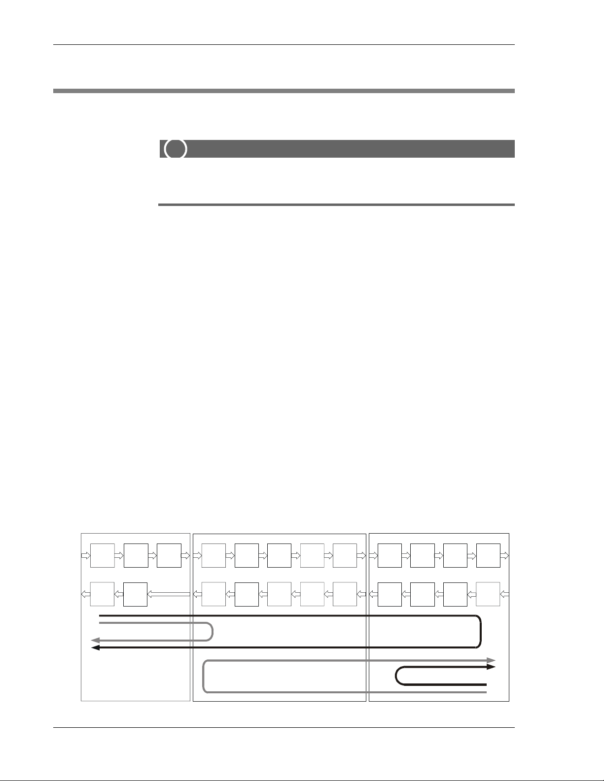
4 Software Operation MIX 56 User Manual
PERFORMING DIAGNOSTICS
Running Loopbacks
ALERT
!
ALERT! When a loopback is running, the low-speed channel or
high-speed circuit on which it is running is out of service.
The following loopbacks can be set from the Loopbacks screen:
Low Speed “Line”: The signal is sent through the DS1 LIU (Line Inter-
face Unit) and looped back before reaching the Encoder/Decoder . The DS1
Received signal is looped back out as the DS1 Transmitted signal.
Low Speed “Local”: The demultiplexed DS1 signal from the M13 MUX
is encoded and sent to the DS1 LIU Equalizer, where it is looped back
through the DS1 LIU Decoder, and then multiplexed and added to the DS3
stream by the M13 MUX.
DS3 LIU
Noise
Crosstalk
Filter
Line
Driver
High-Speed Line
Equalizer
Pulse
Shaper
High Speed “Line DS3”: The received signal is sent through the DS3 LIU
and through the M13 MUX Decoder, where it is looped back through the
Encoder and put onto the DS3 stream. The DS3 Received signal is looped
back out as the DS3 Transmitted signal.
High Speed “Local DS3”: The signal is sent through the DS1 LIUs, multiplexed, and looped back before reaching the M13 MUX Encoder.
High Speed “Line, DS1 Ch xx in DS3”: The signal path is the same as the
“Line, DS3” loopback, but instead of the entire DS3 signal being looped
back, an individual DS1 channel of the Muxed DS3 signal is looped back.
The illustration below shows the path of each loopback.
M13 MUX DS1 LIU
Clock &
Data
Recovery
Decoder
Encoder
DS3
Fram er &
M32
Demux
M23 Mux
& DS3
Framer
DS2
Fram er &
M21
Demux
M12 Mux
& DS2
Framer
Tributary
Mapper
Tributary
Mapper
Tributary
Interface
Tributary
Interface
Encoder
Decoder
Attenuator
Recovery
Low-Speed Local
Jitter
Clock &
Date
Pulse
Shaper
Peak
Detector
Line
Driver
Equalizer
High-Speed Local
Low-Speed Line
MIX 56 Loopback Options
4-46 Telect, Inc. 122188-10 A0
Page 93

MIX 56 User Manual 4 Software Operation
The following remote loopbacks can be requested from the Loopbacks
screen:
Low Speed “Remote Tx LpUp”: Transmits a DS1 Loop Up code for 6
seconds. The MIX 56 uses CSU loop codes.
Low Speed “Remote Tx LpDn”: Transmits a DS1 Loop Down code for 6
seconds. The MIX 56 uses CSU loop codes.
High Speed “Remote DS1 Ch xx in DS3”: Requests a loopback of the individual DS1 signal for Channel xx of the MUXed DS3 signal at the other
end of the DS3 link.
High Speed “Remote All DS1’s in DS3”: Requests a loopback of all DS1
signals of the MUXed DS3 signal at the other end of the DS3 link. This remote loopback request is only available if the DS3 mode is set for C-Bit.
High Speed “Remote DS3 (Line)”: Requests a loopback of the entire
DS3 signal at the other end of the DS3 link. This remote loopback request
is only available if the DS3 mode is set for C-Bit.
NOTES
• The MIX 56 will respond to r eceiving low-speed and high-speed remote
loopback requests if the “Loopback Permission” is set to Yes on the
System Settings screen.
• Low-Speed Loop-Up and Loop-Down codes vary depending on the in-
terface setting and whether they are transmitted or received. The interface setting for the individual DS1 line is set from the Low Speed Configuration Screen.
The Loop-Up and Loop-Down codes and the number of bits in each
code are CSU loop codes, as defined below:
NI Interface CI Interface
Code Bits Code Bits
Rx Loop Up 03 5 01 5
Rx Loop Down 07 5 01 3
Tx Loop Up 01 5 03 5
Tx Loop Down 01 3 07 5
• The low-speed loopback settings of “Remote Tx LpDn” and “Remote
Tx LpUp” causes the MIX 56 to transmit the appropriate loop-up or
loop-down code for 6 seconds and then terminate the transmission.
• The MIX 56 will also respond when receiving the appropriate loop-up
or loop-down code if the “Loopback Permission” setting of the System
122188-10 A0 Telect, Inc.
4-47
Page 94

4 Software Operation MIX 56 User Manual
Settings screen is set to Yes. If loop back permission is set to Yes then
the MIX 56 will —
◊ Go into loopback when the loop-up code is no longer received and
it had received the loop-up code for at least 5 seconds. A loopback
is not established until the loop-up code is no longer received after
being received for at least 5 seconds.
◊ Go out of loopback when the loop-down code has been received for
5 seconds. A loopback is cancelled after receiving the loop-down
code for 5 seconds, it does not wait for the loop-down code to cease
being received.
• The low-speed loop-up and loop-down codes can be received and
transmitted either via the individual DS1 channel of the MUXed DS3
signal or via the corresponding DS1 line. The MIX 56 can be set up to
either the DS3 or DS1 direction but not both at the same time. The lowspeed remote loopback dir ection, DS3 or DS1, is set by the “LS Remote
LB Dir” field of the System Settings screen.
◊ “LS Remote LB Dir” set for DS3 (default): The loop-up and
loop-down codes are received and transmitted on the corresponding
DS1 channel of the MUXed DS3 signal. The loopback set on receiving the loop-up code is the low-speed local loopback. A loopup or loop-down code received on the DS1 line is not recognized.
◊ “LS Remote LB Dir” set for DS1: The loop-up and loop-down
codes are received and transmitted on the corresponding DS1 line.
The loopback set on receiving the loop-up code is the low-speed
line loopback. A loop-up or loop-down code received from the corresponding DS1 channel of the DS3 signal is not recognized.
To run a loopback, proceed as follow:
Step Action
1. From the Directory screen, press 19 to select Loopbacks, then Enter.
The Loopbacks screen appears:
4-48 Telect, Inc. 122188-10 A0
Page 95

MIX 56 User Manual 4 Software Operation
MIX 56 by Telect Rt. Mix56 Directory (CTRL+D)
Help (?)
Loopbacks
-------- LS Chan #: 1 [Apply]
High Speed: None Rx: None
Low Speed: None Rx: None
=============================================================================
# Name DS3 DS1 Status Rx # Name DS3 DS1 Status Rx
-- ------------ ---- ------------- -- -- ------------ ---- ------------- - 1 Low Speed 01 None None No 15 Low Speed 15 None Chan.Disabled...
2 Low Speed 02 None None No 16 Low Speed 16 None Chan.Disabled...
3 Low Speed 03 None Chan.Disabled... 17 Low Speed 17 None Chan.Disabled...
4 Low Speed 04 None Chan.Disabled... 18 Low Speed 18 None Chan.Disabled...
5 Low Speed 05 None None No 19 Low Speed 19 None Chan.Disabled...
6 Low Speed 06 None None No 20 Low Speed 20 .....Chan.Unavail....
7 Low Speed 07 None Chan.Disabled... 21 Low Speed 21 None Chan.Disabled...
8 Low Speed 08 .....Chan.Unavail.... 22 Low Speed 22 None Chan.Disabled...
9 Low Speed 09 None Chan.Disabled... 23 Low Speed 23 None Chan.Disabled...
10 Low Speed 10 None Chan.Disabled... 24 Low Speed 24 None Chan.Disabled...
11 Low Speed 11 None Chan.Disabled... 25 Low Speed 25 None Chan.Disabled...
12 Low Speed 12 None Chan.Disabled... 26 Low Speed 26 None Chan.Disabled...
13 Low Speed 13 None Chan.Disabled... 27 Low Speed 27 None Chan.Disabled...
14 Low Speed 14 None Chan.Disabled... 28 Low Speed 28 None Chan.Disabled...
2. In the LS Chan # field, type the number of the low speed channel
you want to run a loopback on, and then press Enter.
If the selected channel is disabled, “Chan Disabled” will appear in
the Low Speed field. If the selected channel is unavailable,
“Chan Unavail.” will appear in the Low Speed field.
3. Tab to the High Speed field, select a loopback by pressing the spa-
cebar to toggle among “Local , DS3”, “Line, DS3”, “Line DS1 Ch
xx in DS3”, “Remove DS1 Ch xx in DS3”, “Remote All DS1’s in
DS3”, “Remote DS3 (Line)”, or “None”; and then press Enter.
None means a loopback is not running, and therefore, the channel is
operating normally.
4. Tab to the Low Speed field, select a loopback to run on the channel
by pressing the spacebar to toggle among “Local, Line”,
“Remote Tx LpUp”, “Remote Tx LpDn”, or “None”; and then
press Enter.
If the Low Speed Channel is disabled or unavailable, the Low
Speed field is not enabled.
5. T ab to the [Apply] button and press Enter. A prompt appears asking
you to confirm running the loopbacks. The [Apply] button is not
enabled until a change in either the “High Speed” or “Low Speed”
field is made.
122188-10 A0 Telect, Inc.
4-49
Page 96

4 Software Operation MIX 56 User Manual
6. Type y and press Enter. The High Speed field in the upper frame
displays the loopback running on the High Speed circuit. The lower
frame displays the status of the Low Speed channels.
NOTES
• The Rx fields on the Loopback screeen is to display the status of the
MIX 56 receiving any remote loopback requests.
• The DS3 column on the Loopback screen’s lower frame displays the
status of the loopback that is currently set on the corresponding DS1
channel of the MUXed DS3 signal. This DS3 field will display either
“Line” or “Rem”.
BER TESTING
The MIX 56 has a limited set of Bit Error Rate (BER) testing capabilities.
This BER testing is setup from the Craft interface screen 20, “BER Testing”. In the “BER Testing” screen you can specify test mode and test pattern.
The test mode specifies where the test is to be performed. This allows you
to select either a C-Bit DS3 test on the high speed line, a T1/E1 test on a
particular channel of the DS3 high speed line, or an unframed pattern test
on a specific low speed line.
The test pattern selections are dependant on which test mode is selected.
The test patterns available for the different modes are specified in the fol-
lowing table:
Mode Available Patterns
C-Bit DS3 Test on High Speed Line
This test puts a C-Bit DS3 test signal onto
the DS3 high speed line
T1/E1 Test on High Speed Line
This test puts either a T1 or E1 test signal
onto a specific channel of the Muxed DS3
signal on the DS3 high speed line
Unframed Test on Low Speed Line
This test puts an unframed T1 or E1 test
signal onto a specific low speed line
1. Pseudorandom test, PBRS “2^15-1”
2. Pseudorandom test, PBRS “2^20-1”
3. Pseudorandom test, PBRS “2^23-1”
1. Pseudorandom test, PBRS “2^15-1”
2. Pseudorandom test, PBRS “2^20-1”
3. Pseudorandom test, PBRS “2^23-1”
4. Quasi_Random test, PBRS (QRSS)
5. All Ones
6. All Zeros
7. 3 in 24
8. 1 in 8 (1:7)
1. Pseudorandom test, PBRS “2^15-1
2. Quasi_Random test (QRSS)
4-50 Telect, Inc. 122188-10 A0
Page 97

MIX 56 User Manual 4 Software Operation
When test mode “T1/E1 T est on High Speed Line” is selected then you also
specify:
1. Which channel of the muxed DS3 signal to insert the test pattern
on.
2. Whether to use a framed test signal or not.
3. What frame format to use if using a framed test signal.
4. What remote alarm format to use if T1 line and using a framed test
signal
When test mode “Unframed Test on Low Speed Line” is selected then you
also specify which low speed channel to do the test on.
To Specify a BER Test
Step Action
1. From the Directory screen, press 20 to select “BER Testing”, then
press enter. The “BER Testing” screen appears:
MIX 56 by Telect MIX 56 Directory (CTRL+D)
Help (?)
BER Testing
-----------
Mode: T1/E1 Test on High Speed Line
Pattern: Disabled
Receiving Pattern: None
Low Speed Channel #: 1 Line Type: T1
Framed Signal: Yes
Frame Format: ESF
RAI: FS Bit
[Apply]
2. In the “Mode” field select the mode by pressing the spacebar to tog-
122188-10 A0 Telect, Inc.
gle between “CBit DS3 T est on Hi gh Speed Line”, “Unframed Test
on Low Speed Line”, or “T1/E1 T est on High Speed Line” and then
pressing Enter.
4-51
Page 98

4 Software Operation MIX 56 User Manual
NOTE
The DS3 test on the high speed line is a C-Bit DS3 signal. This is
due to the capabilities of the DS3 framer chip we used not being
able to recognize a received test pattern unless the framer chip is
set for C-Bit.
3. Tab to the “Pattern” field and select the desired pattern by pressing
the spacebar to toggle between the available options and then pressing Enter.
The available options depend on the mode selection and are specified in the previous table.
4. Tab to the “Low Speed Channel” field and select the channel by
typing in the number of the desired channel and then pressing enter.
NOTE
This field is only available in the “T1/E1 Test on High Speed Line”
or “Unframed Test on Low Speed Line” modes.
If the selected Low Speed Channel is disabled or unavailable, then
the “Line Type:” display will change to either “Line Disabled” or
“Line Unavail.”
5. Tab to the “Framed Signal” field and toggle between “yes” and
“no” by pressing the spacebar and then pressing Enter.
NOTE
This field is only available in the “T1/E1 Test on High Speed Line”
mode.
6. Tab to the “Frame Format” field and toggle between the available
options by pressing the spacebar and then pressing Enter . The available options depend on whether the line is a T1 or E1. The T1 options are “ESF” and “SF”. The E1 options are “DOUBLE” and
“MULTI”.
NOTE
This field is only available in the “T1/E1 Test on High Speed Line”
mode.
4-52 Telect, Inc. 122188-10 A0
Page 99

MIX 56 User Manual 4 Software Operation
7. Tab to the “RAI” field and toggle between the available options by
pressing the spacebar and then pressing Enter. This field only applies to a T1 signal and selects the remote alarm format (remote
alarm indication, RAI). The available options are bit2 equals zero
in every channel (Bit 2=0) and FS bit of frame 12 of the framed signal (FS Bit).
NOTE
This field is only available in the “T1/E1 Test on High Speed Line”
mode.
8. To apply the BER test selected, tab to the [Apply] button and press
enter. A prompt will appear telling you that this action will cause a
continuous traffic interruption and ask if you want to continue.
If a Low Speed Channel is selected that is either disabled or unavailable, then the [Apply] button is not enabled.
9. Type “y” and Enter to perform the selected BER test.
122188-10 A0 Telect, Inc.
4-53
Page 100

4 Software Operation MIX 56 User Manual
4-54 Telect, Inc. 122188-10 A0
 Loading...