

Page 1
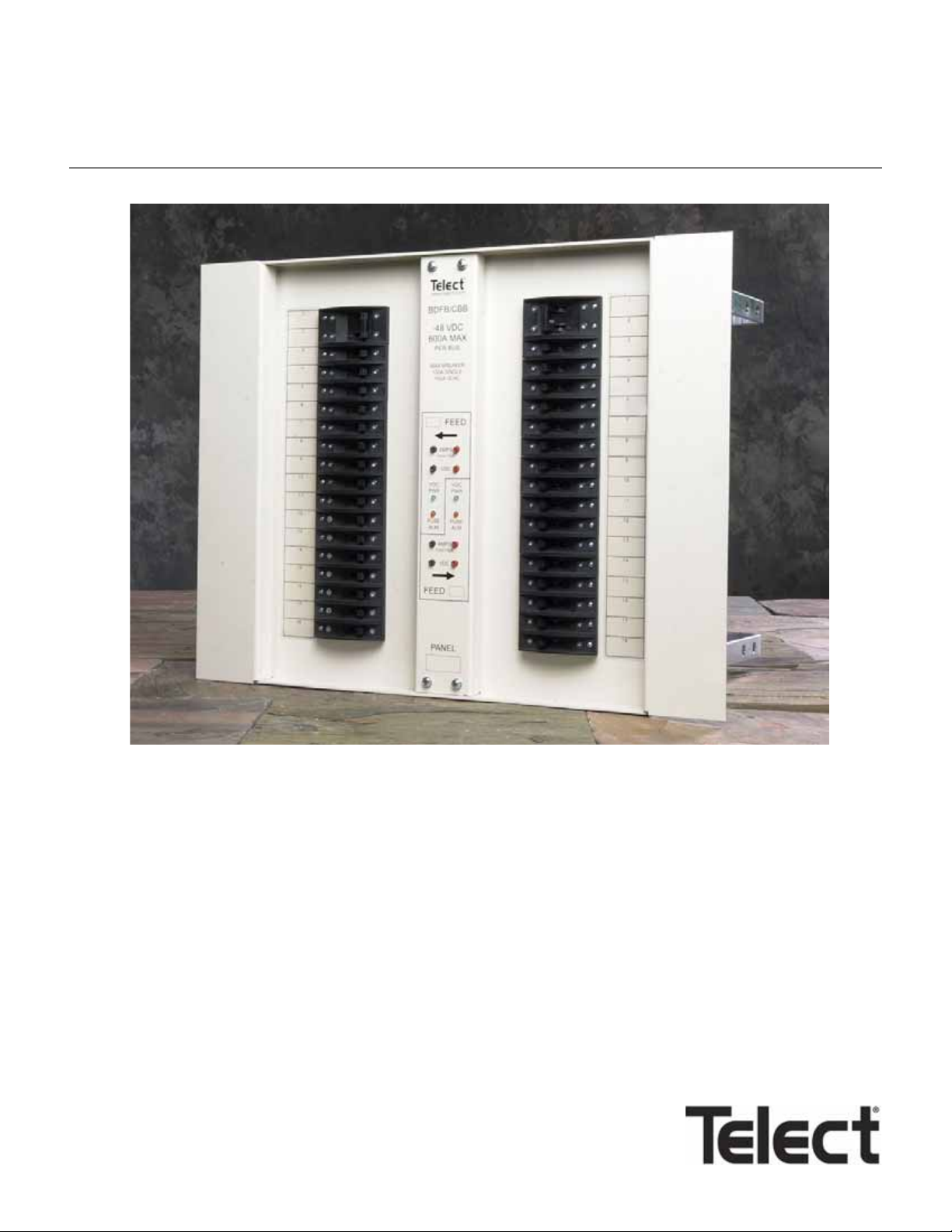
Dual 600A BDFB / BDCBB
Model 007-0001-2600
User Manual 122645-5 A0
Page 2

Telect, Inc. • USA +1.509.926.6000 • Mexico +1.52.33.3836.3700
Poland +1.48.713.239.100 • UK +1.44.1489.889500 • www.telect.com
Copyright © 2002 Telect, Inc., All Rights Reserved
ii
Page 3

Content s
1 Descriptions
Dual 600A BDFB / BDCBB ............................................................................................................................ 1-1
Capabilities .............................................................................................................................................. 1-1
Features................................................................................................................................................... 1-1
Specifications................................................................................................................................................. 1-3
2 Installation
Installation Considerations............................................................................................................................. 2-1
Tools and Equipment............................................................................................................................... 2-1
Technical Support.................................................................................................................................... 2-1
Inspection....................................................................................................................................................... 2-1
Bay Layout ..................................................................................................................................................... 2-1
Panel Installation............................................................................................................................................ 2-2
Cable Installation............................................................................................................................................ 2-4
A. Install Ground Cabling......................................................................................................................... 2-5
B. Install Input Cabling............................................................................................................................. 2-6
C. Install Intrabay & Interbay Cabling ...................................................................................................... 2-8
D. Install Alarm Cabling ........................................................................................................................... 2-8
E. Test Inputs & Alarms Without Breakers .............................................................................................. 2-9
F. Install Output Cabling ........................................................................................................................ 2-10
Circuit Breaker Installation ........................................................................................................................... 2-11
3 Output Testing
4 Service
Owner Maintenance....................................................................................................................................... 4-1
In Case Of Difficulty........................................................................................................................................ 4-1
In-Warranty Service........................................................................................................................................ 4-1
Out-Of-Warranty Service................................................................................................................................ 4-1
Repacking For Shipment................................................................................................................................ 4-2
5 Accessories
Telect, Inc. • USA +1.509.926.6000 • Mexico +1.52.33.3836.3700
Poland +1.48.713.239.100 • UK +1.44.1489.889500 • www.telect.com
Copyright © 2002 Telect, Inc., All Rights Reserved • Telect Publication 122645-5 A0
Page 4

Telect, Inc. • USA +1.509.926.6000 • Mexico +1.52.33.3836.3700
Poland +1.48.713.239.100 • UK +1.44.1489.889500 • www.telect.com
Copyright © 2002 Telect, Inc., All Rights Reserved
Page iv
Page 5
1. Description
— Features
• Suitable for primary or secondary distribution
• Modular design expands capability of rack to as much as
4800A
• Open architecture provides easy input/output cabling
• Top-down or bottom-up cabling
• Standard “bullet terminal” circuit breakers (up to 100A
per position)
• Breaker shunting allows double-pole, single distribution
up to 150A
• Alarm and BATT monitor overcurrent protection
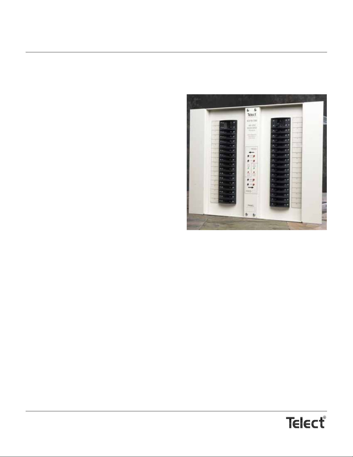
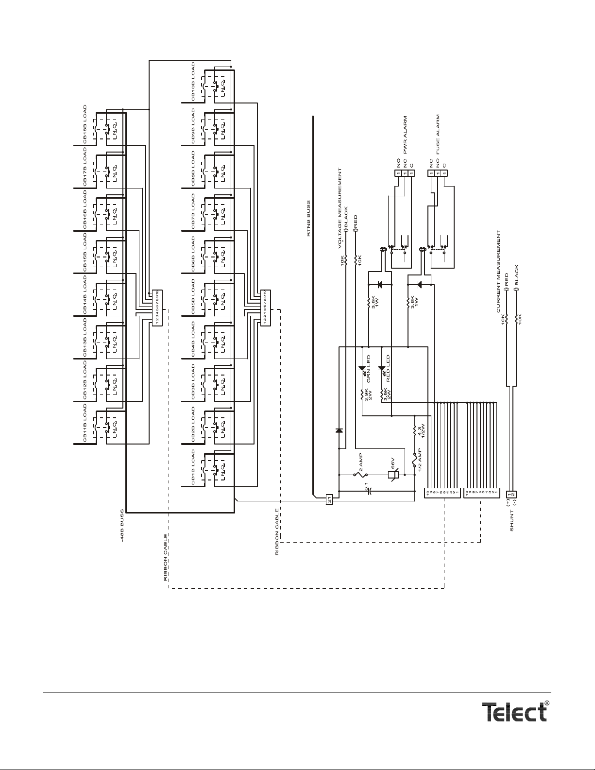
DUAL 600A BDFB / BDCBB
Telect’s Dual 600A Battery Distribution Fuse Board / Circuit
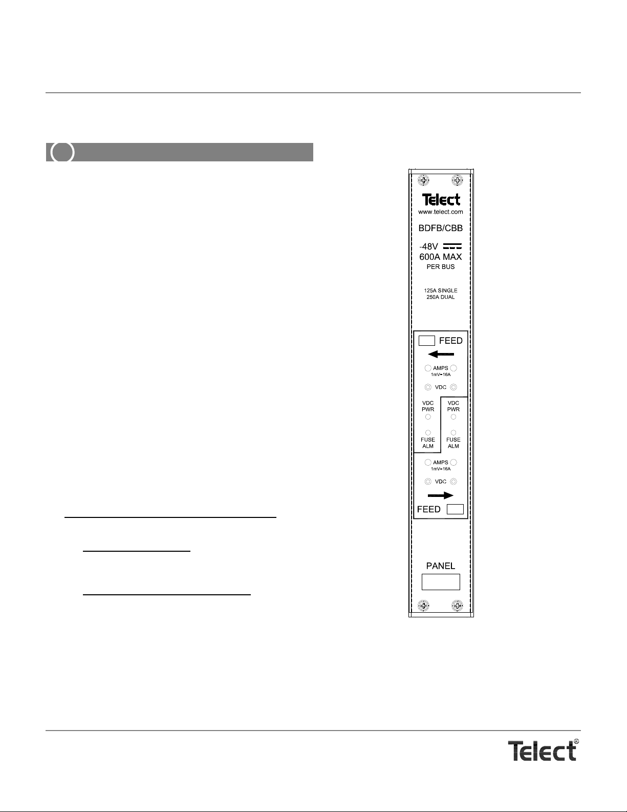
Breaker Board (BDFB / BDCBB), Model 007-0001-2600, contains
two non-shared sets of input buses. Both sets of -48VDC/RTN input buses are capable of 600A primary distribution feed to 18 circuit breaker output positions.
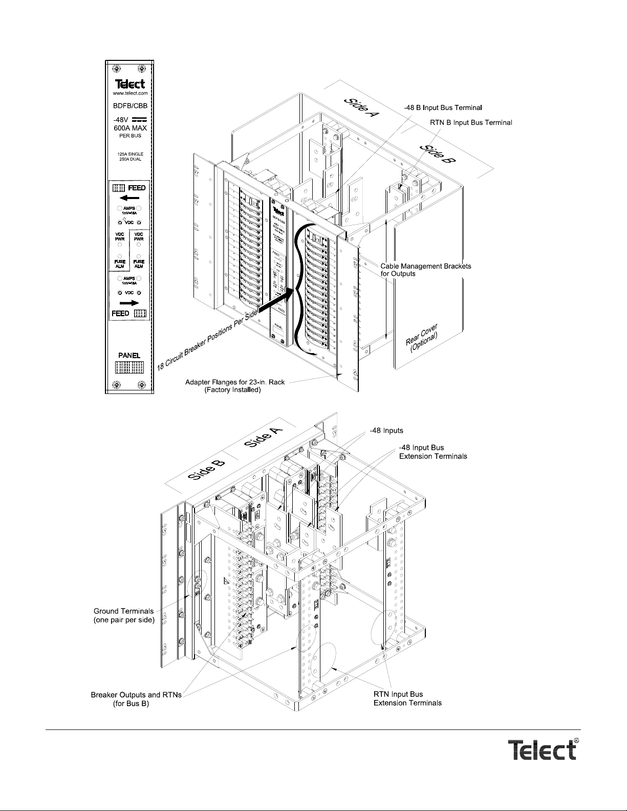
The open-frame architecture of the BDFB / BDCBB allows unrestricted top-down or bottom-up cabling of inputs and outputs.
The front panel contains 18 circuit breaker positions per feed for a
total of 36 per panel. Each position accepts a standard “bullet terminal” circuit breaker rated up to 100A, with the capability of pairing adjacent breakers for dual-pole outputs of up to 150A. Vdc
Power LED, Fuse Alarm LED, and input voltage test points
the standard removable alarm panel
ing.
2
provide input/feed monitor-
1
on
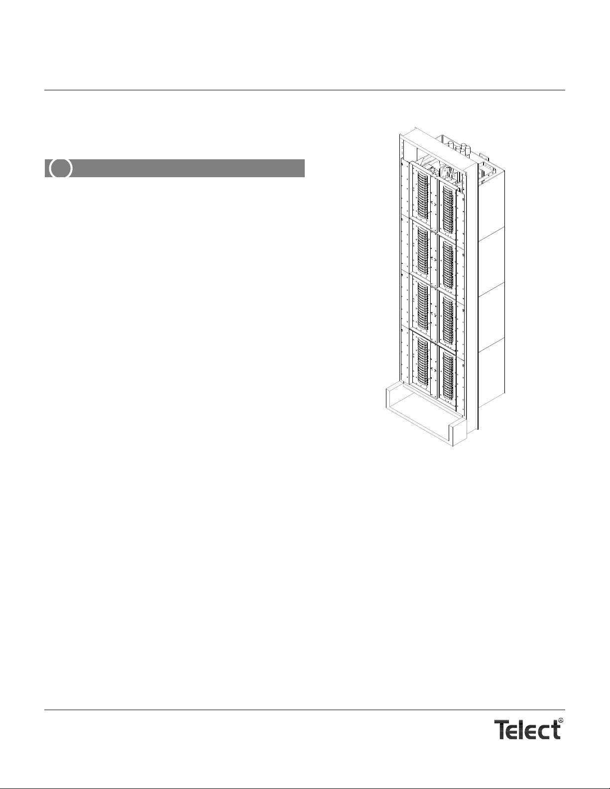
Telect’s Dual 600A BDFB / BDCBB fits standard 19 in. or 23 in.
racks set up for either EIA or WECO mounting. Up to four panels
can be arranged in a bay
per bay).
3
to provide up to 2400A per feed (4800A
— Capabilities
Each Panel
•Dual Feed
• 600A (Max.,Continuous) Per Feed
• 800A (Max.) Interrupt Device Per Feed
• 18 Outputs Per Feed; 36 Outputs Per Panel
Full Bay of Four Panels
•Dual Feed
• 2400A (Max., Continuous) Per Feed
• 3200A (Max.) Interrupt Device Per Feed
• 72 Outputs Per Feed; 144 Outputs Per Bay
1. Input current test points require an optional shunt and
cabling. Contact telect.com for availability. (See Section 5,
Accessories.)
2. Optional removable alarm panels provide digital voltage
and current meters. Contact telect.com for availability.
(See Section 5, Accessories.)
3. When installing four panels in a bay, prefer a 23-in. bay
rather than a 19-in. bay to reduce cable congestion.
Telect, Inc. • USA +1.509.926.6000 • Mexico +1.52.33.3836.3700
Poland +1.48.713.239.100 • UK +1.44.1489.889500 • www.telect.com
Copyright © 2002 Telect, Inc., All Rights Reserved • Telect Publication 122645-5 A0
Page 6
Telect, Inc. • USA +1.509.926.6000 • Mexico +1.52.33.3836.3700
Poland +1.48.713.239.100 • UK +1.44.1489.889500 • www.telect.com
Copyright © 2002 Telect, Inc., All Rights Reserved
Page 1-2
Page 7
SPECIFICATIONS
Mechanical Specifications
Ground Terminals Quantity: 2 Pair
Stud Size: 1/4 in.
Cable Size: Up to #1/0 AWG (one per lug), de pending on input interruption device.
Lug: Dual-hole compression lug with
1/4 in. dia. holes (7 mm) on 3/4 in.
(19 mm) centers
1
Lug Fasteners: 1/4 - 20 KEPS nuts and flat washers
Socket Size for Nut: 7/16 in. (12 mm)
Maximum Torque: 6 ft-lb (8.13 N•m)
Input Terminal Bus Plate Number of Plates: Total 4: 1 BATT & 1 RTN per feed.
Each terminal plate capable of
supporting up to two, dual-hole input
lugs (standard configuration)
Hole Size in Plate: .406 in. dia. (10 mm) on 1 in.
(25.4 mm) centers
Cable Size: One 750/777.7MCM (max.) per
-48Vdc or RTN lug. (Size of cable
depends on size of input interruption
device and plant voltage drop
requirements.)
Lug: Dual-hole compression for hole and
cable size specified above
3
Lug Fasteners: Grade 2, 3/8 - 16 bolts, nuts, lock
washers, and flat washers
Socket Size: 9/16 in. (14 mm) for bolt heads and
nuts
Maximum torque: 17 ft-lb (~23 N•m)
Output Breakers & Terminals Breakers: Total 36 (18 per feed), bullet-style
Terminals:
Quantity: One per single or double breaker
Stud Size: 1/4 in.
Cable Size: • For single-pole breakers, one,
#2 AWG (max.) per lug
• For double-pole breakers, one,
#1/0 AWG (max.) per lug
4
Lugs: Dual-hole compression with 1/4 in.
dia. holes on 3/4 in. (19 mm) centers
Lug Fasteners: 1/4 - 20 KEPS nuts and flat washers
Socket Size for Nut: 7/16 in. (12 mm)
Maximum torque: 6 ft-lb (8.13 N•m)
Output RTN Terminal Bus Plate Number of Plates: One bus plate per feed accommo-
dates 18 output RTN lugs
Hole Size in Plates: 1/4 in. dia. (7 mm) on 3/4 in. (19 mm)
centers
Cable Size: • For single-pole breakers, one,
#2 AWG (max.) per lug
• For double-pole breakers, one,
#1/0 AWG (max.) per lug
Lugs: Dual-hole compression for hole and
cable size specified above
3
2
Lug Fasteners: Grade 2, 1/4 - 20 bolts, KEPS nuts,
and flat washers
Socket Size: 7/16 in. (12 mm) for bolt heads and
nuts
Maximum torque: 6 ft-lb (8.13 N•m)
2
.
2
1. See Lug Chart on 9 for suggested manufacturers.
2. Up to four dual-hole input lugs with the optional RTN external bus bar extension kit.
3. See Lug Chart on 9 for approved manufacturers.
4. Double-pole breakers require an optional two-pole adapter.
Telect, Inc. • USA +1.509.926.6000 • Mexico +1.52.33.3836.3700
Poland +1.48.713.239.100 • UK +1.44.1489.889500 • www.telect.com
Copyright © 2002 Telect, Inc., All Rights Reserved
Page 1-3
Page 8
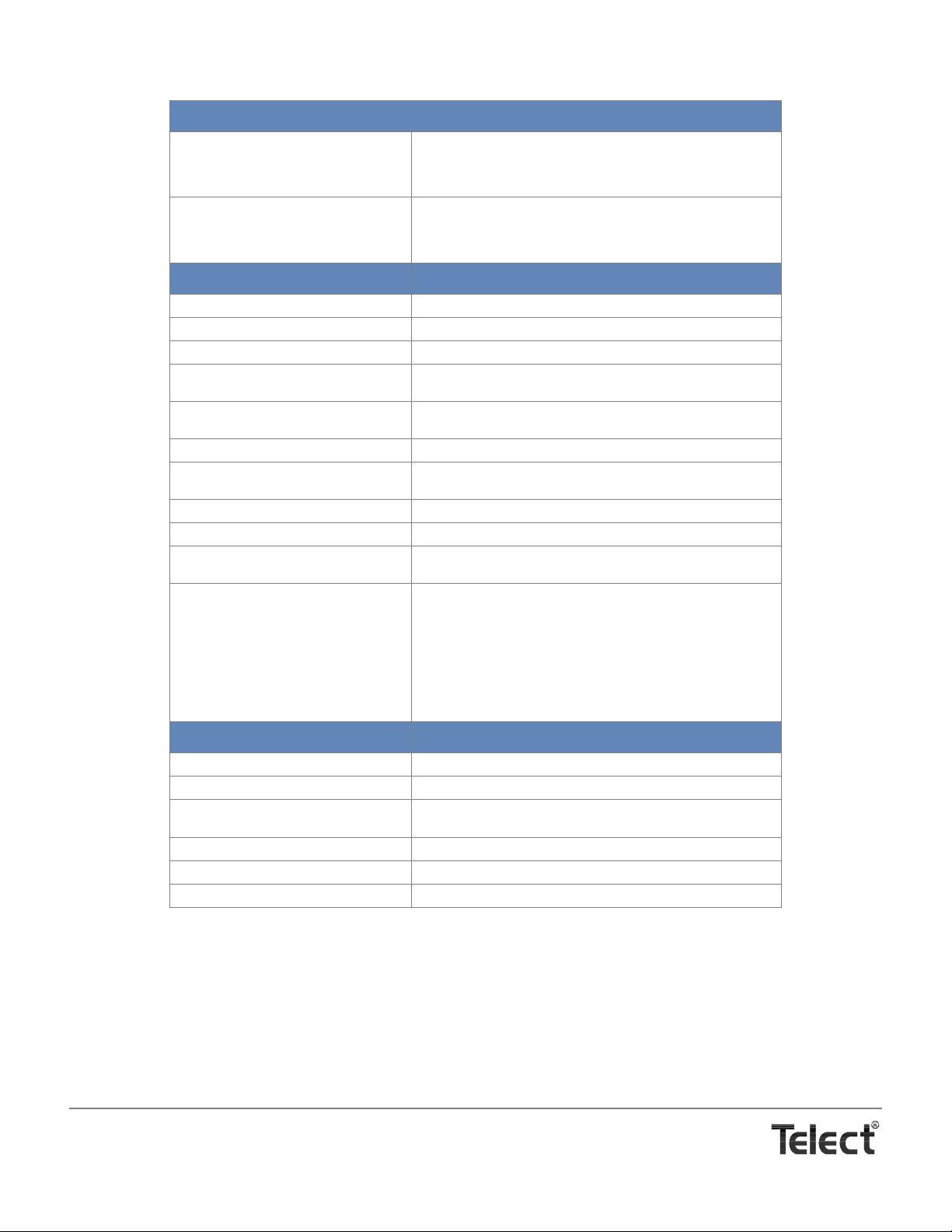
Mechanical Specifications (continued)
Alarm Terminals, Standard Quantity: 6 contacts per side for NO or NC pow-
er and breaker (fuse) alarms
Type: Cage clamp (WAGO style)
Wire Size: 18-24 AWG
Input Test Points (each side):
For .080-in. test probes, where BLK is meter common and RED is
meter volts:
Standard Test Points
Optional Test Points
1
VDC
AMPS, where 1mV scale = 16A
Electrical Specifications
Operating Voltages –48Vdc nominal (-40 to –60 Vdc range)
Maximum Input Interruption Device 800A per feed
Maximum Continuous Input Load 600A per feed per panel
Maximum Output Interruption Device 100A per single-pole circuit breaker
Maximum Continuous Output Load 80A per single-pole circuit breaker
Max. Voltage Drop .25Vdc
Max. surface temperature of breakers at
26°C (79°F) ambient
Max. panel heat dissipation at full load 225W/m
Percentage of full load heat dissipation Less than 0.5%
Alarm Relay Contacts 2A @ 30 Vdc
Max. Alarm Card Power Rating @20V: 35 mA (0.70 W)
150A per double-pole circuit breaker
120A per double-pole circuit breaker
37°C (99°F)
2
per meter (20.9W/ft2/ft)
0.6A @ 60 VDC
@20V: 35 mA (0.70 W)
@24V: 44 mA (1.06 W)
@27V: 48 mA (1.30 W)
@30V: 51 mA (1.53 W)
@42V: 59 mA (2.48 W)
@48V: 64 mA (3.07 W)
@56V: 69 mA (3.86 W)
@60V: 73 mA (4.38 W)
Physical/Environmental
Weight, Shipping ~150 lb (~70 kg)
Weight Without Packaging or Breakers 63 lb (29 kg)
Rack Mounting 19 in. (482.6 mm), EIA/WECO
23 in. (584.2 mm), EIA/WECO
Operating Temperature Range -5ºC to +55ºC (23ºF to 131ºF)
Storage Temperature Range -40ºC to +85ºC (-40ºF to +185ºF)
Humidity 0-90%, noncondensing
1. Requires an optional shunt.
Telect, Inc. • USA +1.509.926.6000 • Mexico +1.52.33.3836.3700
Poland +1.48.713.239.100 • UK +1.44.1489.889500 • www.telect.com
Copyright © 2002 Telect, Inc., All Rights Reserved
Page 1-4
Page 9
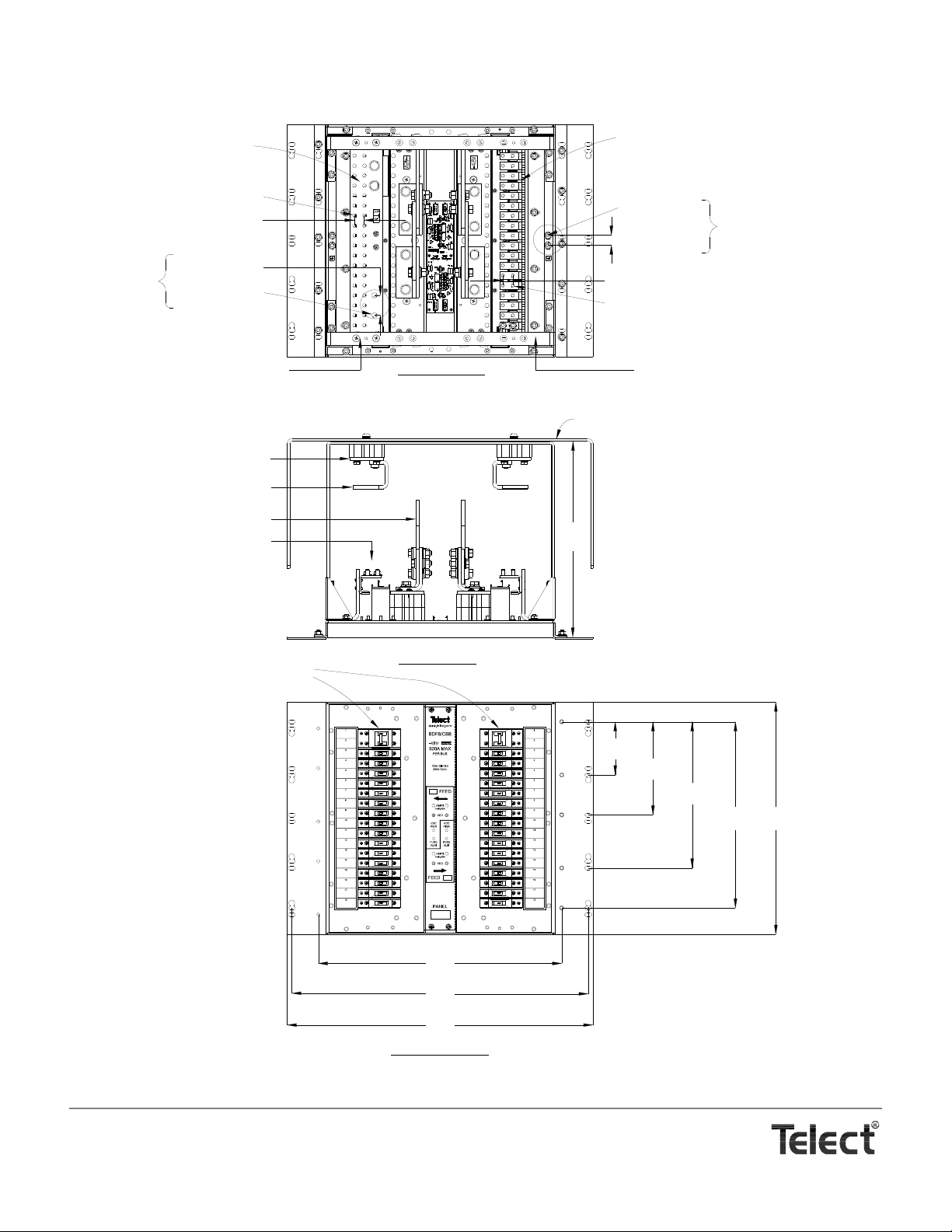
Side B
4.00
(10.16)
(44.37)
17.47
14.00
(35.56)
(27.94)
11.00
(1 of 2 Provided)
Connections
Ground
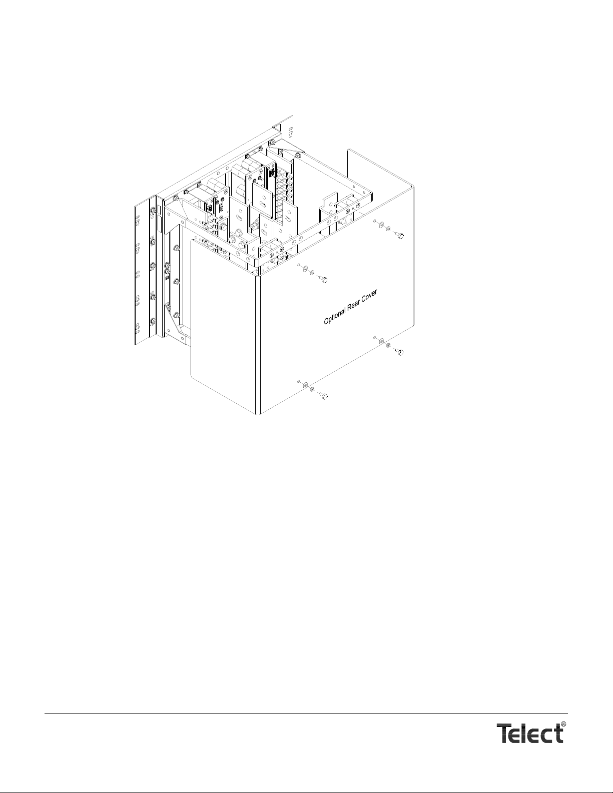
Optional Rear Cover
(Panel is Shipped Without Breakers.)
Normal Breaker Layout is Shown H e r e.
RTN B Outputs
}
(1.03)
(ROTATED AND SHOWN WITHOUT
OPTIONAL COVER AND RTN A BUS)
REAR VIEW
}
Side A Breaker Outputs
1/4-20 Stud & KEPS
.750
(1.90)
Center Spacing
for Viewing Breaker
1/4-20 Stud & KEPS
Center Spacing
(1.90)
.750
Outputs
RTN A Bus Removed
Alarm
Board
Hole Dia.
Center Spacing
RTN B Bus
Center Spacing
Hole Dia.
Connection Provided
for Strapping Input
RTN to an Extension
Panel
(1.90)
(3.81)
1.50
.406
.750
.266
(.676)
RTN A Output Terminal Plate
RTN A Input Terminal Plate
-48 A Input Terminal Plate
Side A Breaker Outputs
}
(37.46)
14.75
FRONT VIEW
TOP VIEW
(46.51)
(56.67)
(58.42)
18.31
22.31
23.00
Side A
(17.78)
7.00
Telect, Inc. • USA +1.509.926.6000 • Mexico +1.52.33.3836.3700
Poland +1.48.713.239.100 • UK +1.44.1489.889500 • www.telect.com
Copyright © 2002 Telect, Inc., All Rights Reserved
Page 1-5
Page 10
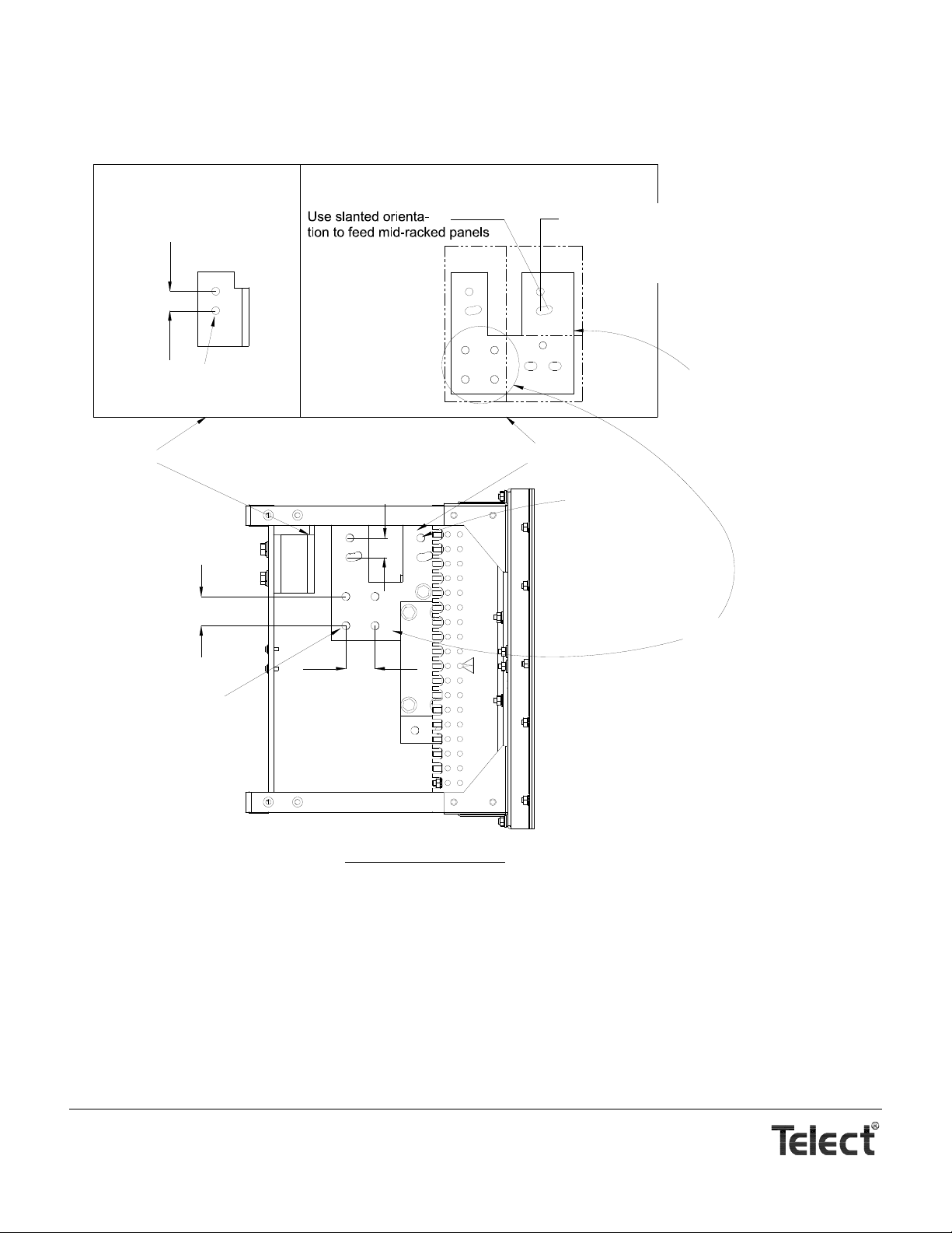
Connection Provided
for Strapping Input
BATT to an Extension
Panel
(2.54)
1.00
RTN A Input Terminal
Center Spacing
(2.54)
Hole Dia.
(1.03)
.406
RTN A Input Terminal
(Rotated)
1.00
Use vertical orientation for highest
panel in a top-down input feed or
lowest panel in a bottom-up
input feed.
Input Lug
Mounting
-48 A Input Terminal
Holes
Holes
-48 A Input Terminal
Front of Terminal
Plate
Center Spacing
(1.03)
Holes for Intra-Bay Busing
Hole Dia.
.406
LEFT SIDE VIEW
(3.81)
1.50
Center Spacing
Hole Dia.
(1.03)
.406
(3.81)
Center Spacing
1.50
Telect, Inc. • USA +1.509.926.6000 • Mexico +1.52.33.3836.3700
Poland +1.48.713.239.100 • UK +1.44.1489.889500 • www.telect.com
Copyright © 2002 Telect, Inc., All Rights Reserved
Page 1-6
Page 11
Telect, Inc. • USA +1.509.926.6000 • Mexico +1.52.33.3836.3700
Poland +1.48.713.239.100 • UK +1.44.1489.889500 • www.telect.com
Copyright © 2002 Telect, Inc., All Rights Reserved
Page 1-7
Page 12
Telect, Inc. • USA +1.509.926.6000 • Mexico +1.52.33.3836.3700
Poland +1.48.713.239.100 • UK +1.44.1489.889500 • www.telect.com
Copyright © 2002 Telect, Inc., All Rights Reserved
Page 1-8
Page 13
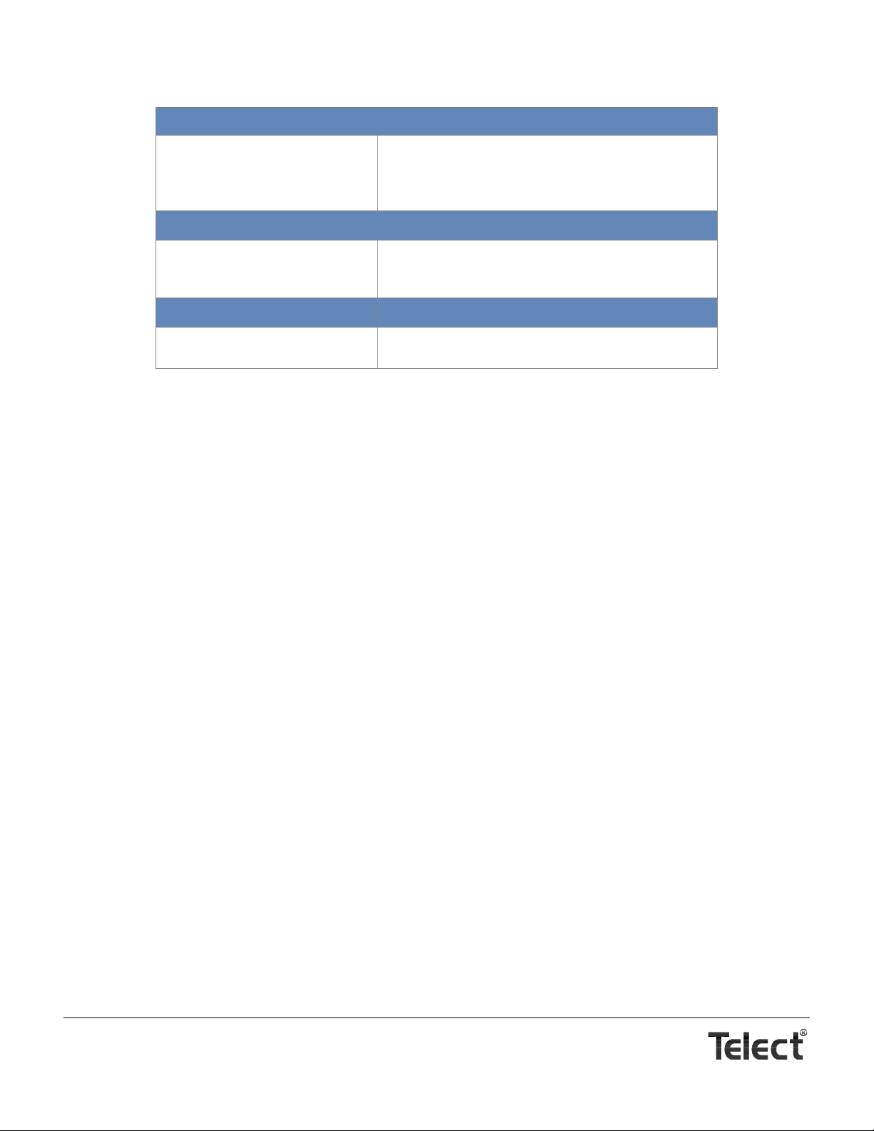
LUG CHART
Rack Ground Terminals (for #1/0 AWG)
Flex Cable (266 Strand)
Code Cable (19 Strand)
Burndy: YAV25-L2TC14E2-FX
Panduit: LCD2/0-14B-X
Burndy: YA25L-2TC14E2
Panduit: LCD1/0-14B-X
Input Terminals (for 750MCM, Nominal)
Flex Cable (1850 Strand)
Code Cable (61 Strand)
Burndy: YA44-L2NT38-FX
T&B: 58825NT
Burndy: YA39L-2TC38
Load & RTN Terminals (for #2 AWG)
Code Cable (7 Strand) Burndy: YA2CL-2TC14E2
Panduit: LCD2-14B-Q
Telect, Inc. • USA +1.509.926.6000 • Mexico +1.52.33.3836.3700
Poland +1.48.713.239.100 • UK +1.44.1489.889500 • www.telect.com
Copyright © 2002 Telect, Inc., All Rights Reserved
Page 1-9
Page 14

Telect, Inc. • USA +1.509.926.6000 • Mexico +1.52.33.3836.3700
Poland +1.48.713.239.100 • UK +1.44.1489.889500 • www.telect.com
Copyright © 2002 Telect, Inc., All Rights Reserved
Page 1-10
Page 15
2. Installation
ALERT
!
INSTALLATION CONSIDERATIONS
ALERT! This product must be installed and maint ained
only by qualified personnel. Verify all connections
meet requirements specified in local electric codes or
operating company guidelin es before supplying power .
Protect this equipment with a fuse or breaker sufficient
to interrupt power levels specified in Section 1 of this
manual.
— Tools and Equipment
•7/16 in. (or 12 mm) socket for 1/4-in. bolts and KEPS nuts
9
/16 (or 14 mm) socket for 3/8-in. bolts and nuts
•
• #2 Phillips screwdriver (screwdriver for cross-recessed
screws)
• standard electrical cabling tools (cable lacing, crimping
and stripping tools, cable cutters, etc.)
— Technical Support
By e-mail: [email protected]
By phone: 888-821-4856 or 509-921-6161
INSPECTION
Compare the contents of the shipping container with the packing
list. Call Telect if anything is missing.
NOTE
Telect is not liable for shipping damage.
If the shipping container is damaged, keep it for the carrier’s
inspection. Notify the carrier and call Telect’s Customer Service Department:
1-800-551-4567 or 1-509-926-6000
Keep the container until you have checked equipment opera-
tion. If you experience any kind of problem, call Telect’s Customer Service Department. Use the original, undamaged container if you are instructed to return the BDFB / BDCBB to
Telect.
BAY LAYOUT
In a standard bay, each BDFB / BDCBB requires 10 EIA
rack positions (10 RU). Up to four BDFB / BDCBB panels
can populate a bay having either 19-in. or 23-in. racks (either EIA or WECO spacing).
Telect, Inc. • USA +1.509.926.6000 • Mexico +1.52.33.3836.3700
Poland +1.48.713.239.100 • UK +1.44.1489.889500 • www.telect.com
Copyright © 2002 Telect, Inc., All Rights Reserved • Telect Publication 122645-5 A0
Page 16
PANEL INSTALLATION
1. If applicable, remove optional rear cover of panel (four, 1/4-20 hexhead bolts).
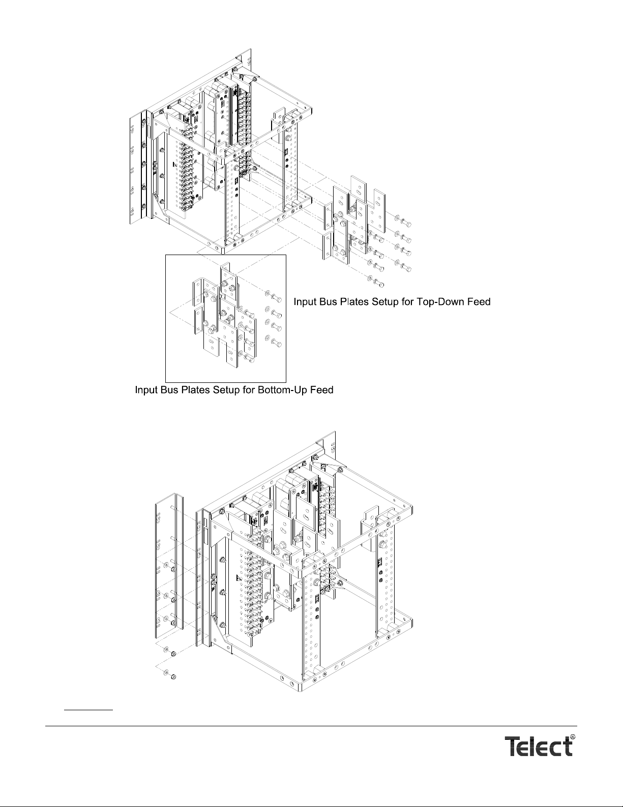
2. Decide if input cables will be fed from bottom-up or top-down.
NOTE
Panels are shipped from the factory for top-down input cable entrance to bay. If you intend to feed input cables from the bottomup, you must reverse the input terminal plates, as instructed in the following procedure.
If necessary, to change both input buses from top-down to bottom-up input cable entrance, refer to the following illustration and
proceed as follows:
3
a. Remove four,
/8-in. hex head cap screws securing each input bus assembly to panel.
b. Rotate this assembly for input bus A and resecure it where the bus B had been, and vice versa.
c. Torque bolts to 18 ft-lb (~24 N•m).
Telect, Inc. • USA +1.509.926.6000 • Mexico +1.52.33.3836.3700
Poland +1.48.713.239.100 • UK +1.44.1489.889500 • www.telect.com
Copyright © 2002 Telect, Inc., All Rights Reserved
Page 2-2
Page 17
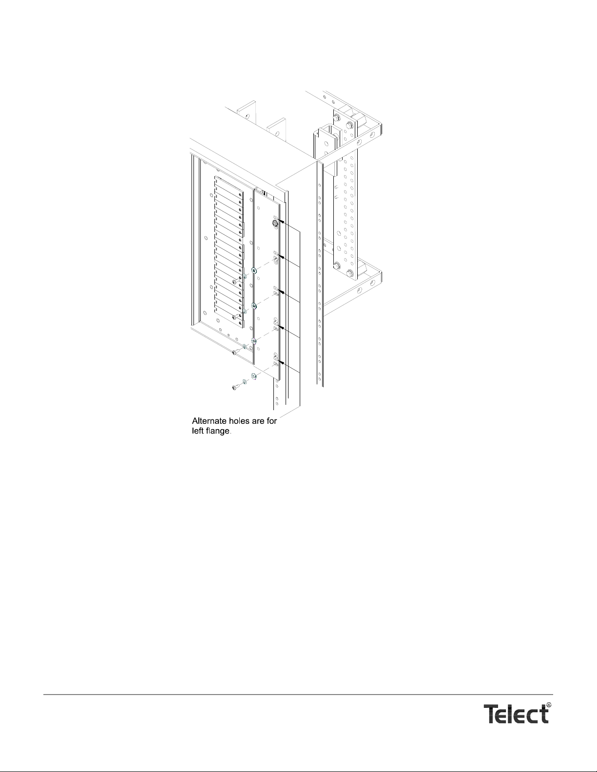
3. If panel is to be mounted to a 19-in rack, remove adapter plate on each side of
the panel (five,
1
/4-20 KEPS nuts).
4. If applicable, install optional shunts and cabling for current monitor. (See instructions included with shunt kit.)
Telect, Inc. • USA +1.509.926.6000 • Mexico +1.52.33.3836.3700
Poland +1.48.713.239.100 • UK +1.44.1489.889500 • www.telect.com
Copyright © 2002 Telect, Inc., All Rights Reserved
Page 2-3
Page 18
5. If applicable, install optional digital metering control module in place of standard control module. (See instructions included with
metering control module.)
6. Partially thread two topmost fasteners (#12-20 screws, provided) for mounting panel onto bay.
7. Place panel’s keyhole mounting slots over topmost fasteners.
8. Loosely secure the mounting flange with four additional fasten ers along each side.
9. Torque all but keyhole mounting fasteners to 35 in.-lb (4.29 N•m).
10. Remove keyhole fasteners installed in Step 4, and re-install along with a flat washer and a lock washer. Torque as directed in
Step 9.
11. Install all other panels in bay before cabling.
CABLE INSTALLATION
Use Telect’s Wire Size Guide (117995) for help in cable selection.
NOTE
Cables must conform to local operating company guidelines as well as national, regional, and local electrical codes.
Only use components and crimping tools approved by agencies or certifying bodie s recognized in your country or region such
as Underwriter’s Laboratories (UL), TUV, etc.
Telect, Inc. • USA +1.509.926.6000 • Mexico +1.52.33.3836.3700
Poland +1.48.713.239.100 • UK +1.44.1489.889500 • www.telect.com
Copyright © 2002 Telect, Inc., All Rights Reserved
Page 2-4
Page 19
Follow the prescribed order in this subsection to install and test all cabling and alarm features:
DANGER
!
A.Install Ground Cabling
B.Install Input Cabling
C.Install Intrabay & Interbay Cabling
D. Install Alarm Cabling
E.Test Inputs and Alarms Without Circuit Breakers
F.Install Output Cabling
— A. Install Ground Cabling
DANGER! DANGER! Failure to properly ground this equipment can create hazardous conditions to installation personnel and to the equipment.
GEFAHR! Bei unsachgemäßer Erdung besteht Gefahr für das Installationspersonal und das Gerät!
¡PELIGRO! La conexión incorrecta a tierra puede ser peligrosa tanto para los instaladores como para el equi-
po.
DANGER ! Si vous ne reliez pas correctement cet équipement à la terre, son utilisation présente des dangers
pour la personne qui l'installe ainsi que pour l'équipement.
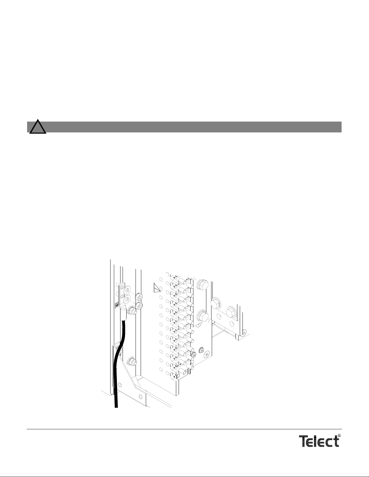
A ground terminal is located near each of the panel’s mounting fla nges. You need only connect to one of the grounds, as shown in
the following illustration.
1. Use a UL-approved crimping tool to attach a UL-approved, 2-hole compression lug onto a ground wire.
Size of ground depends on input interruption device.
2. Lightly coat anti-oxidant electrical joint compound on lug, grounding terminal, and surrounding contacting surface. Then, connect lug to terminal using
1
/4-in. KEPS nuts and washers from studs.
1
1. Refer to NEC Article 250-122 or IEEE grounding guidelines. Also, check operating company guidelines.
Telect, Inc. • USA +1.509.926.6000 • Mexico +1.52.33.3836.3700
Poland +1.48.713.239.100 • UK +1.44.1489.889500 • www.telect.com
Copyright © 2002 Telect, Inc., All Rights Reserved
Page 2-5
Page 20

3. Torque ground connection to 6 ft-lb (8.13 N•m).
4. Likewise, secure the connectorized opposite end of the ground cable to a bare metal portion of the bay’s frame or the conductor-to-office-ground system. (If necessary scrape paint from the frame and use electrical joint compound to ensure good ground
contact.)
— B. Install Input Cabling
• For top-down input feeds, begin cabling to the topmost panel and then work your way down the bay.
• For bottom-up input feeds, beg i n at the bottom and work your way up the bay.
Finish all input cabling in a bay before beginning any output cabling in that same bay.
NOTES
• Keep in mind that Feeds A and B are independent (unshared) feeds.
• Input cabling to the BDFB / BDCBB must support 125% of the total, rated, continuous load currents of the equipment
powered by the BDFB / BDCBB. Remember: The maximum continuous load per feed is 600A.
• Consider inherent voltage drop in determining input wire size. Remember to choose wire size based on the circuit break-
er/fuse size and not
on the expected load. Use the standard formula to check wire size:
(11.1) x (fuse size) x (total wire length in ft)
Max.Vdc Drop =
(circular mils of wire used)
Proceed as follows to cable inputs to each side of the panel:
1. Use a UL-approved crimping tool to attach a UL-approved, dual-hole 750/777.7 MCM compre ssion lugs onto appropriate
cables. Insulate lug barrels as required.
2. Clean terminals and lugs with a nonabrasive, nonmetallic pad.
3. Feed input cabling down (or up for a bottomfeed ) in to th e re ar central area of the panel — that is, between the outp u t cab l e
management brackets — to the topmost BDFB / BDCBB (or bottommost for an upfeed).
4. Lightly coat anti-oxidant electrical join t compound on lugs and -48 input terminal plates.
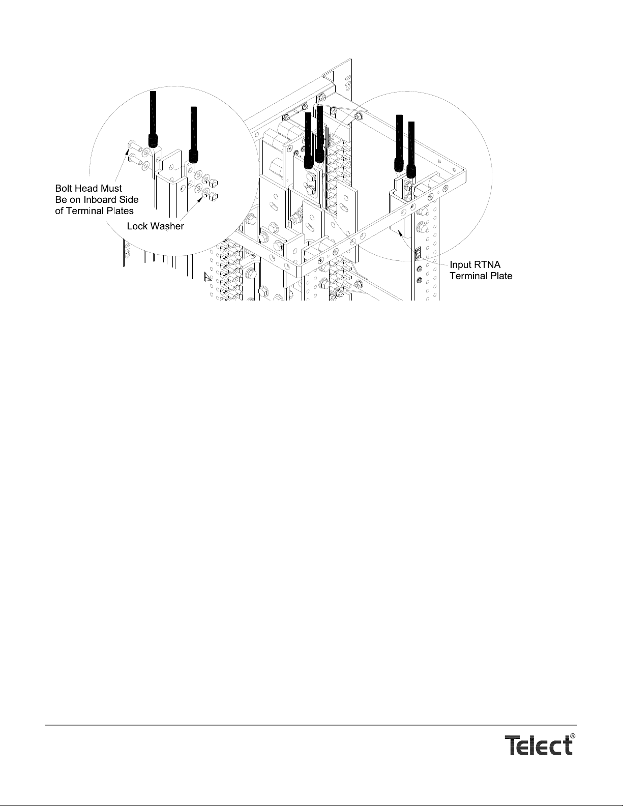
5. Use a 3/8-16, grade 2 bolt, washers, and nut (all provided) to secure the first pair of -48 cabling to the -48 input bus terminal
plate:
• If two lugs are used, remember to attach lugs to opposite faces of the terminal plate. DON’T STACK LUGS on one side of
the terminal plate.
• Always route cables in a neat orderly manner to ensure that the cables exert no pulling or twisting forces on the input and
return terminal plates. DON’T ALLOW TERMINAL PLATES to support the weight of or to restrain the cable.
NOTE
The input lugs on the topmost terminal (or bottommost for an upfeed) are connecte d, as shown on the following page, so that
the lugs are held straight up on the sides of the terminal plate. Subsequent cables and lugs to the inbe tween panels in the bay
can be pivoted up to 25º off of vertical to allow easier cable management access through out the bay.
Telect, Inc. • USA +1.509.926.6000 • Mexico +1.52.33.3836.3700
Poland +1.48.713.239.100 • UK +1.44.1489.889500 • www.telect.com
Copyright © 2002 Telect, Inc., All Rights Reserved
Page 2-6
Page 21
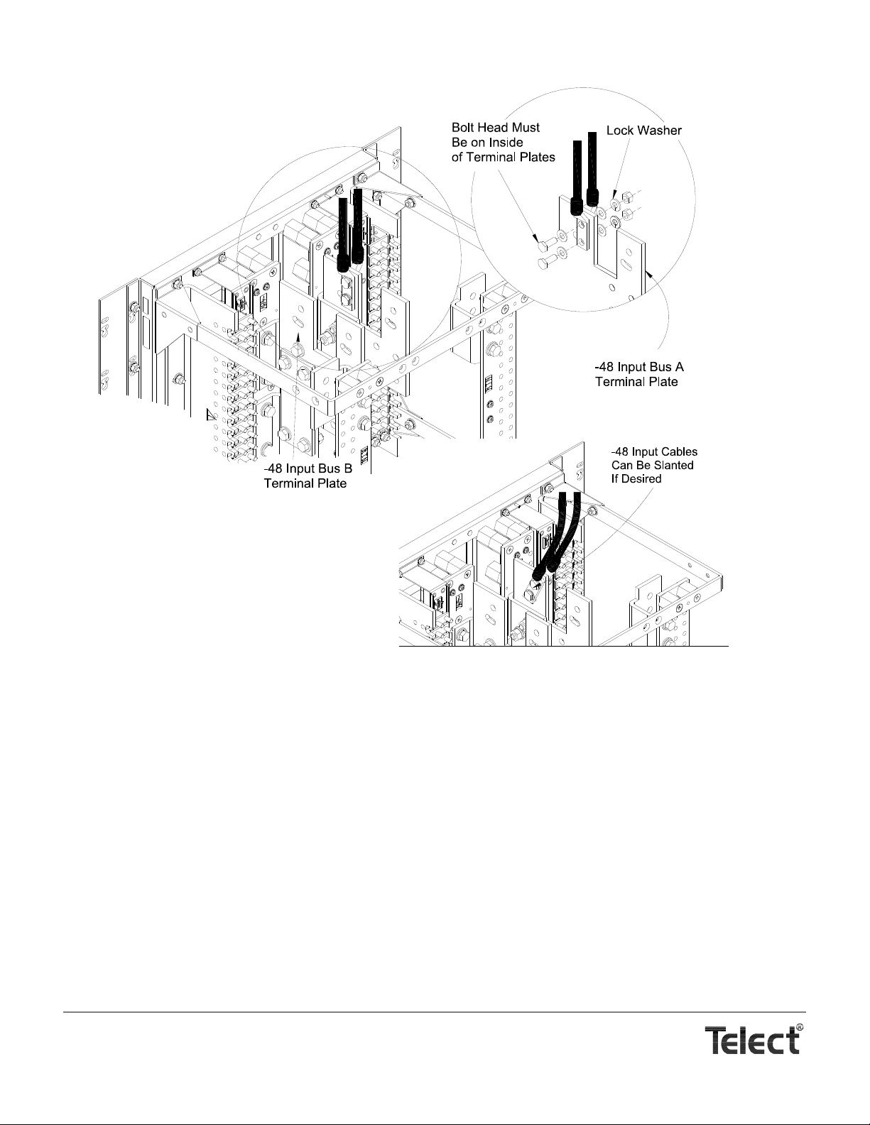
6. Torque input BATT connections to 36 ft-lb (48.81 N•m).
7. In a similar fashion, for the input RTN —
a. Use a UL-approved crimping tool to attach a UL-approved, dual-hole 750/777.7 MCM compre ssion lugs onto appropriate
RTN cables. Insulate lug barrels as required.
b. Clean RTN terminal plate and lugs with a nonabrasive, nonmetallic pad.
c. Lightly coat anti-oxidant electrical joint compound on lugs and RTN input terminal plates.
3
d. Use a
/8-16, grade 2 bolts, washers, and nuts (all provided) to secure the first pair of RTN cabling to the RTN input bus ter-
minal plate. (See the following illustration.)
• If two lugs are used, remember to attach lugs to opposite faces of the terminal plate. DON’T STACK LUGS on one side
of the terminal plate.
• Always route cables in a neat orderly manner to ensure that the cables exert no pulling or twisting forces on the input
and return terminal plates. DON’T ALLOW TERMINAL PLATES to support the weight of or to restrain the cable.
Telect, Inc. • USA +1.509.926.6000 • Mexico +1.52.33.3836.3700
Poland +1.48.713.239.100 • UK +1.44.1489.889500 • www.telect.com
Copyright © 2002 Telect, Inc., All Rights Reserved
Page 2-7
Page 22
— C. Install Intrabay & Interbay Cabling
The input -48 and RTN plates contain mounting holes for bus extensions to other panels in the same bay. Telect has busing and cabling kits for all types of input extensions.
— D. Install Alarm Cabling
External indicators (monitors) can be connected to the BDFB / BDCBB alarm board. The external indicators can be wired to accept
either a normally open or closed circuit when the VDC PWR or FUSE ALM LEDs or other optional alarms are activated.
To connect power- and fuse-alarm circuits to the BDFB / BDCBB, proceed as follows:
1. Refer to the following illustration and then remove four Phillips screws (screws with cross-recessed heads) securing alarm
panel.
2. Carefully pull off and turn alarm panel cover around.
3. Strip off ¼ in. of insulation on end of a pair of 18-24 AWG alarm wires for each external alarm circuit desired.
4. Select a common (C) contact and either a normally closed (NC) or normally open (NO) contact for each alarm desired:
• For a C and NC pair , expect continuity (0 Ω) during normal operation and an open circuit (∞ Ω) for an alarm condition such
as an open breaker or a power failure.
•For C and NO pair , expect an open circuit (∞ Ω) during normal operation and continuity (0 Ω) for an alarm condition such as
an open breaker or a power failure.
Telect, Inc. • USA +1.509.926.6000 • Mexico +1.52.33.3836.3700
Poland +1.48.713.239.100 • UK +1.44.1489.889500 • www.telect.com
Copyright © 2002 Telect, Inc., All Rights Reserved
Page 2-8
Page 23
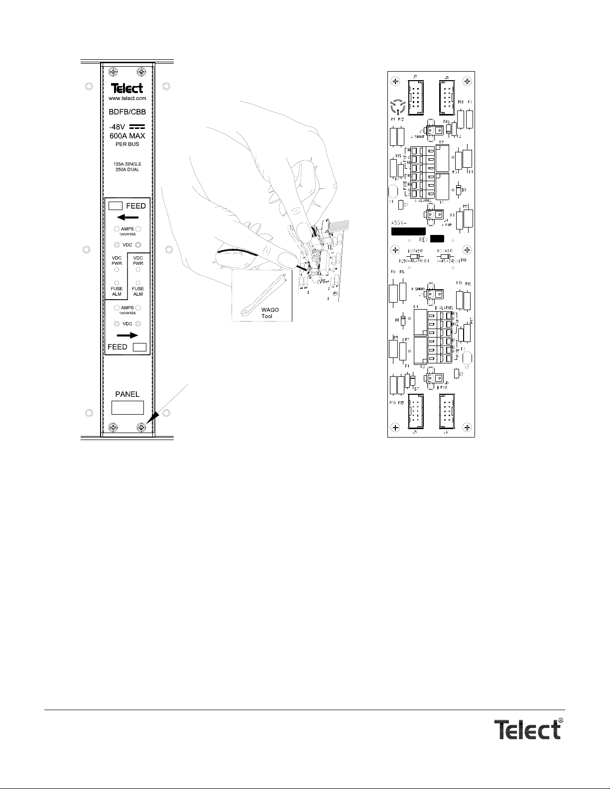
5. For each contact, insert WAGO tool (supplied) into connector to release contact’s cage-clamp jaws. Insert wire and then pull out
Alarm Board on
Rear of Panel Cover
(1X)
(2X)
Front
Rear
Remove 4 Screws
to Remove Panel Cover
tool to cinch.
6. When finished with Feed A and B alarm wiring, resecure alarm panel cover.
— E. Test Inputs & Alarms Without Breakers
1. Make sure BDFB / BDCBB contains no circuit breakers.
2. Turn on Feed A input power.
• Verify that VDC PWR lamp turns green.
• Verify that FUSE ALM lamp is not lit.
3. Use a DVM with standard .080-in. test probes to verify power and polarity at panel’s VDC test points for Feed A:
• Connect panel RED (-48Vdc) to meter RED (voltage).
• Connect panel BLK (RTN) to meter BLK (common).
4. Use an ohmmeter at alarm monitor to verify alarm conditions.
Telect, Inc. • USA +1.509.926.6000 • Mexico +1.52.33.3836.3700
Poland +1.48.713.239.100 • UK +1.44.1489.889500 • www.telect.com
Copyright © 2002 Telect, Inc., All Rights Reserved
Page 2-9
Page 24
With Feed A power OK and without any installed circuit breakers, expect either continuity (0 Ω) between C and NC poles and/or
ALERT
!
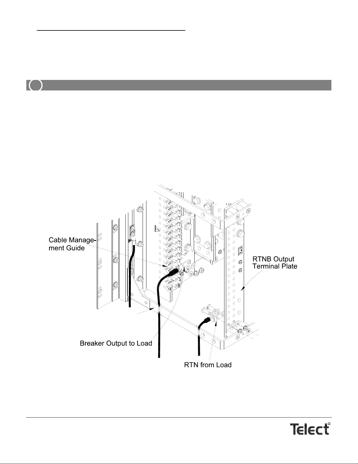
Cable Management Bracket
an open circuit (∞ Ω) between C and NO.
5. Repeat procedure for Feed B.
— F. Install Output Cabling
ALERT! Feeds A and B may be powered. Use voltmeter to verify, and then proceed accordingly.
Remember to finish all input cabling (including all intrabay and interbay input cabling) before proceeding with output cabling in that
bay.
Proceed as follows to cable panel outputs:
1. Use a UL-approved crimping tool to attach UL-approved, dual-hole compression lugs onto each pair of copper output and return
cables (up to #2 AWG), as required by NEC. Insulate lug barrels as required.
Size of cables is determined by size of breaker intended for that cable.
2. Clean terminals and lugs with a nonabrasive, nonmetallic pad.
3. Plan to route and restrain cables along the outside of the cable management brackets, as indicated in the following illustration.
Telect, Inc. • USA +1.509.926.6000 • Mexico +1.52.33.3836.3700
Poland +1.48.713.239.100 • UK +1.44.1489.889500 • www.telect.com
Copyright © 2002 Telect, Inc., All Rights Reserved
Page 2-10
Page 25
4. For a breaker output —
CAUTION
!
CAUTION
!
a. Remove washers and KEPS nuts from appropriate output studs.
b. Lightly coat anti-oxidant electrical joint compound on both lug and studs.
c. Fit lug onto studs, secure lug with washers and KEPS nuts, and then tighten to 6 ft-lb (8.13 N•m).
5. For an output return
a. Lightly coat anti-oxidant electrical joint compound on both lug and return terminal plate.
1
b. Use
c. Tighten nuts and bolts to 6 ft-lb (8.13 N•m).
6. Arrange cables neatly.
Unless directed otherwise by operating company guideline, prefer to use lacing cord to bundle and secure cables.
7. If applicable, re-install optional rear cover.
8. Install breakers as detailed in the following subsection, and then test the panel using the procedure in Section 3, Output Testing.
/4-20, grade 2 bolts, washers, and KEPS nuts to secure lug.
—
CIRCUIT BREAKER INSTALLATION
CAUTION! Do not install breakers with breakers switched on. Doing so may damage breakers or panel.
Local electrical and operating company guidelines recommend that the individual load not exceed 80% of cir-
cuit breaker capacity (for example, 50A breaker x .80 = 40A max. load). Total continuous load for all outputs
must not exceed 600A per bus.
VORSICHT! Keine Trennschalter installieren, während die Trennschalter eingeschaltet sind. Die
Nichtbeachtung dieser Vorschrift kann zu Schäden an den Trennschaltern oder an der Schalttafel führen.
Wir empfehlen eine einzelne Schaltkreisbelastung von nicht mehr als 80 % der Trennschalterkapazität
(z.B. 50 A Schalter x 0,80 = 40 A max. Last). Die Gesamtlast für alle Ausgänge darf 600 A nicht überschreiten.
PRECAUCIÓN: No instale disyuntores adicionales cuando los otros estén conectados, ya que éstos y el panel
podrían resultar dañados.
Recomendamos que la carga individual no exceda el 80% de la capacidad de los disyuntores del circuito (por
ejemplo, un disyuntor de 50 amperios x 0,80 = 40 amperios de carga máxima). La carga total de todas las salidas no debe sobrepasar los 600 amperios po r bus.
ATTENTION ! N'installez pas de disjoncteurs lorsque ceux-ci sont dans la position alimentation ouverte. Vous
risqueriez d'endommager le panneau ou les disjoncteurs.
Nous vous recommandons de vous assurer que la charge individuelle d'un disjoncteur n'excède pas 80 % de
sa capacité maximale (par exemple, un disjoncteur de 50 A ne doit pas être soumis à une charge supérieure à
40 A). La charge totale de toutes les sorties ne doit dépasser 600 A par bus.
CAUTION! Use of non-approved circuit breakers may cause severe damage to the alarm panel and/or digital
metering panel. USE OF NON-APPROVED CIRCUIT BREAKERS WILL VOID WARRANTY.
Telect, Inc. • USA +1.509.926.6000 • Mexico +1.52.33.3836.3700
Poland +1.48.713.239.100 • UK +1.44.1489.889500 • www.telect.com
Copyright © 2002 Telect, Inc., All Rights Reserved
Page 2-11
Page 26
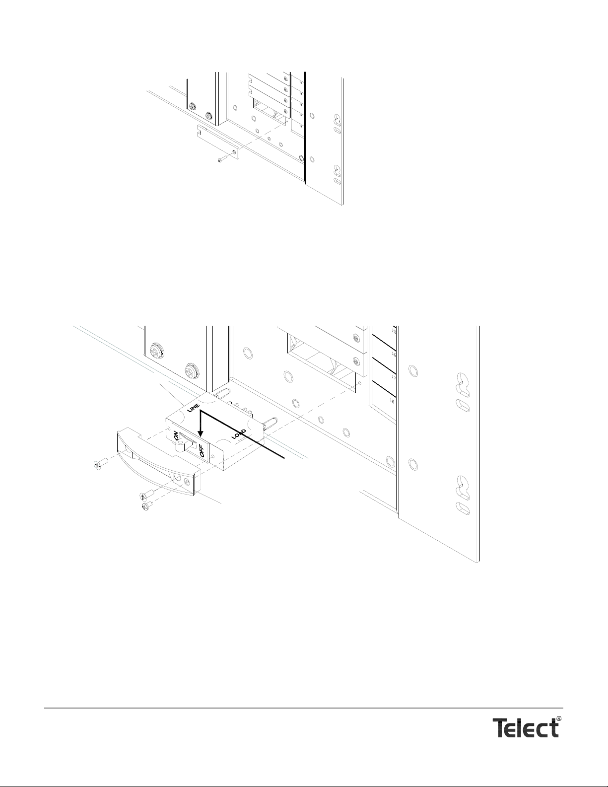
1. Remove blank faceplate at intended breaker position.
Telect breaker face plate
Circuit breaker
OFF is on the right for
Side B, as shown here.
(OFF is on the left for Side A.)
2. Before installing a breaker, screw face plate to breaker, as shown in the following illustration.
NOTE
Breakers are installed in the panel so that the OFF position is toward the outboard side of the panel. In other words, install
breakers so that the LOAD side is toward the outside edge of the panel; that is, LOAD should be on the right on Side B, as
shown below, and on the left on Side A.
3. Make sure breaker is off and then install firmly in panel. Use screw to secure breaker to panel.
4. Label output on designation label next to circuit breaker.
5. Proceed to test the BDFB / BDCBB, as outlined in the next section, Output Testing, before turning on circuit breakers for the first
time.
Telect, Inc. • USA +1.509.926.6000 • Mexico +1.52.33.3836.3700
Poland +1.48.713.239.100 • UK +1.44.1489.889500 • www.telect.com
Copyright © 2002 Telect, Inc., All Rights Reserved
Page 2-12
Page 27
3. Output Testing
ALERT
!
ALERT! This product must be installed and maint ained
only by qualified personnel. Verify all connections
meet requirements specified in local electric codes or
operating company guidelin es before supplying power .
Protect this equipment with a fuse or breaker sufficient
to interrupt power levels specified in Section 1 of this
manual.
1. For initial startup, make sure all BDFB / BDCBB circuit breakers and all inputs at output loads are disabled (disconn ected
or off).
2. With Feed A and B to panel turned on —
• Verify that VDC PWR lamps turn green.
• Verify that FUSE ALM lamps turn red.
NOTE
The FUSE A LM lamp will light if any circuit breaker on the
corresponding bus is off.
3. Use a DVM with standard .080-in. test probes to re-verify
power at panel’s VDC test points for Feed A:
• Connect panel RED (-48Vdc) to meter RED (voltage).
• Connect panel BLK (RTN) to meter BLK (common).
4. Use an ohmmeter at alarm monitor to verify alarm conditions
for each feed.
With input feed OK, but with any circuit breaker OFF
the following feed conditions:
• For the power alarm circuit
between C and NC poles or an open circuit (∞ Ω)
between C and NO.
• For the circuit breaker (fuse) alarm circuit
an open circuit (∞ Ω) between C and NC poles or continuity (0 Ω) between and C and NO.
5. Make sure power is disabled at the first load and then turn on
the corresponding BDFB / BDCBB circuit breaker.
6. Use a DVM to test power and polarity at input terminals of
load.
7. Turn on the corresponding load and verify proper load operation.
, expect either continuity (0 Ω)
, expect
, expect either
Telect, Inc. • USA +1.509.926.6000 • Mexico +1.52.33.3836.3700
Poland +1.48.713.239.100 • UK +1.44.1489.889500 • www.telect.com
Copyright © 2002 Telect, Inc., All Rights Reserved • Telect Publication 122645-5 A0
Page 28

8. Repeat Steps 5 through 7 for all other breakers and corresponding loads.
After the last breaker is turned on, the FUSE ALM lamp must go off.
9. Use an ohmmeter at alarm monitor to verify powered-up circuit bre aker (fuse) alarm condition.
With all circuit breakers ON and powered up, expect either continuity (0 Ω) between C and NC poles or an open circuit (∞ Ω) be-
tween and C and NO.
Telect, Inc. • USA +1.509.926.6000 • Mexico +1.52.33.3836.3700
Poland +1.48.713.239.100 • UK +1.44.1489.889500 • www.telect.com
Copyright © 2002 Telect, Inc., All Rights Reserved
Page 3-2
Page 29

4. Service
ALERT
!
ALERT! This product must be installed and maintained only by qualified personnel. Verify all connections
meet requirements specified in local electric codes or operating company guidel ines before supplying power.
Protect this equipment with a fuse or breaker sufficient to interrupt power levels specified in Section 1 of this
manual.
OWNER MAINTENANCE
Telect’s Dual 600A BDFB / BDCBB (007-0001-2600) does not need preventive maintenance.
IN CASE OF DIFFICULTY
If problems occur after initial installation, check all cable con nections and the installation instructions in Section 2.
For technical support, contact Telect —
By e-mail: [email protected]
By phone: 888-821-4856 or 509-921-6161
IN-WARRANTY SERVICE
Contact your Telect equipment distributor, or call a Telect Customer Service Representative:
1-800-551-4567
1-509-926-6000
Telect will repair or replace defective products within the limits of the warranty. See “Repacking for Shipment” in this section.
NOTE
Call a Customer Service Representative for a Return Material Authorization (RMA) before returning any equipment.
OUT-OF-WARRANTY SERVICE
The procedure for out-of-warranty service is the same as for in-warranty service, except that Telect charges a processing fee, and
you must submit a Purchase Order along with a Return Material Authorization (RMA) before returning equipment. Call a Customer
Service Representative for help getting these forms.
The processing fee guarantees a repair estimate and is credited again s t actual material and labor costs.
Telect, Inc. • USA +1.509.926.6000 • Mexico +1.52.33.3836.3700
Poland +1.48.713.239.100 • UK +1.44.1489.889500 • www.telect.com
Copyright © 2002 Telect, Inc., All Rights Reserved • Telect Publication 1
22645-5 A0
Page 30

REPACKING FOR SHIPMENT
1. T ag the equipment showing owner’s name, address, and telephone number, together with a detailed description of the problem.
2. Use the original shipping container if possible. If you do not have it, package the equipment to prevent shipping damage. Include the RMA inside the container and legibly print the RMA number on the inside and outside of the package (outside near the
address label).
3. Insure the package.
NOTE
Telect is not liable for shipping damage.
Telect, Inc. • USA +1.509.926.6000 • Mexico +1.52.33.3836.3700
Poland +1.48.713.239.100 • UK +1.44.1489.889500 • www.telect.com
Copyright © 2002 Telect, Inc., All Rights Reserved
Page 4-2
Page 31
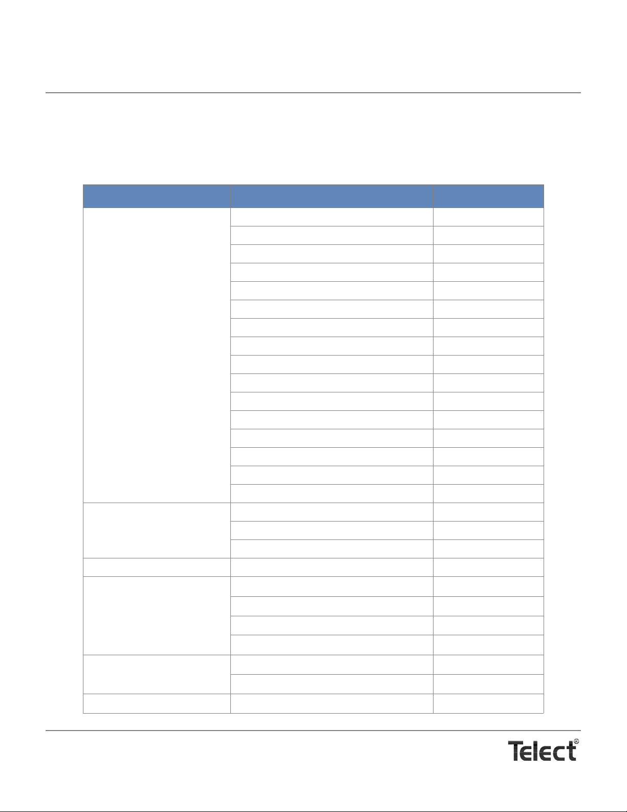
5. Accessories
The following lists optional and replacement items for the Dual 600A BDFB / BDCBB (007-0001-2600). Contact Telect for price and
availability. For input and output wiring and circuit breaker selection, please refer to Wire Sizing & Label Convention Guide (Telect
Part No. 117995) included with your panel.
Item Description Part Number
Single-Pole Circuit Breakers
(Magnetic, 65Vdc, Long Delay, Slim
1
Line)
Double-Pole Breaker
(Magnetic, 65Vdc, Long Delay, Slim
1
Line)
1A 090-0052-1001
2A 090-0052-1002
3A 090-0052-1003
5A 090-0052-1005
10A 090-0052-1010
15A 090-0052-1015
20A 090-0052-1020
30A 090-0052-1030
40A 090-0052-1040
50A 090-0052-1050
60A 090-0052-1060
70A 090-0052-1070
80A 090-0052-1080
90A 090-0052-1090
100A 090-0052-1100
Face plate/cover 090-0001-0021
125A long delay with adapter
150A long delay with adapter
2
2
090-0052-2125
090-0052-2150
Face plate/cover 090-0001-0022
No Circuit Breaker Blank plate kit 090-0001-0020
Shunt Kits 400A 007-0006-0400
600A 007-0006-0600
800A 007-0006-0800
1000A 007-0006-1000
Alarm/Metering Panel Standard alarm with test points 007-0003-0001
Dual digital display with std alarm & test points 007-0003-0002
ETSI Bracket Adapter Kit Use instead of EIA/WECO mounting brackets 007-0000-0100
Telect, Inc. • USA +1.509.926.6000 • Mexico +1.52.33.3836.3700
Poland +1.48.713.239.100 • UK +1.44.1489.889500 • www.telect.com
Copyright © 2002 Telect, Inc., All Rights Reserved • Telect Publication 122635-5 A0
Page 32
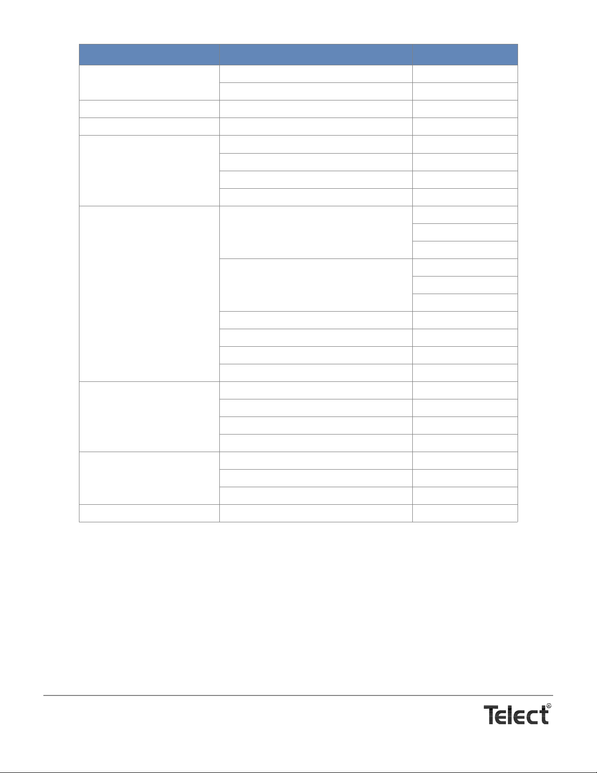
Item Description Part Number
Front Cover, Blank Covers 17.5-in. space in a 23-in. rack 007-0000-0102
Covers 17.5-in. space in a 19-in. rack 007-0000-0103
Rear Safety Cover Clear heat-resistant wrap 007-0000-0010
Designation Label For vertical array of 18 CB positions 122845
Internal Bus Kits Links BATT input buses of 2 BDFB/BDCBBs
Links return buses of two BDFB / BDCBBs
Expander for input battery bus
Expander
for return bus
External Return Bus Kits For 12 or 15 in. cable rack
4
4
5
:¾ in.c/c holes 007-0000-0115
1 in. c/c holes 007-0000-0 215
1 in. & ¾ in. c/c holes 007-0000-0315
For 20 in. cable rack5:¾ in. c/c holes 007-0000-0120
1 in. c/c holes 007-0000-0 220
1 in. & ¾ in. c/c holes 007-0000-0320
Brackets for 1.5 in.-deep cable rack
Brackets for a 2 in.-deep cable rack
13
Expansion, Common
Expansion, Insulated
007-0000-0122
13
007-0000-0123
Lug Fastener Kits For 36, dual-lug load returns
For 10, dual-lug load returns (spares)
For 4, dual-lug, input battery or returns
For 2, internal Input bus expanders
12
12
14
007-0000-0225
14
15
007-0000-0230
16
3
3
007-0002-0010
007-0002-0020
007-0002-0012
007-0002-0022
007-0000-0121
007-0000-0125
007-0000-0231
007-0000-0232
6
7
8
9
10
11
Relay Racks, 7-ft Seismic EIA with unequal flanges, white 723-0707-2130-001
WECO with unequal flanges, white 723-0701-2130-001
End Panel, white 071-3000-0002
Enclosed Cabinet Standard Zone 4 for up to 4 BDFB / BDCBBs contact Telect
1. Contact Telect for alternate circuit breakers, such as mid-trip or short delay. SEE CAUTION THAT FOLLOWS.
2. The adapter bridges adjacent single-pole CB slots for use with double-pole breakers.
3. Each expansion kit contains parts and fasteners to link adjacent (above/below) BDFB / BDCBBs in a rack. Three
kits are required to link a maximum of four, 10RU BDFB / BDCBBs per rack.
4. Bracket and fasteners used to expand from four 750/777.7MCM input positions to six to accommodate up to four
multiple 600A BDFB / BDCBBs in a 2400A rack.
5. Each kit contains parts and fasteners to install an overhead return bus to the plant’s 12 in,-, 15 in.-, or 20 in.-wide
ladder rack system. Each copper plate handles multiple dual-lug connections for a total 600A continuous load at
800A max. load. External return buses accommodate dual lugs with ¾ in. and/or 1 in. center-to-center (c/c) hole
spacings. Brackets for 1.5 in.- versus 2.0 in.-deep cable racks are ordered separately.
6. 32 sets of dual holes. Lugs can be bolted to both sides for a total of 64 lug connections.
7. 16 sets of dual holes. Lugs can be bolted to both sides for a total of 32 lug connections.
8. 12 sets of dual holes with 1 in. center spacing; 22 sets of dual holes with ¾ in. center spacing. (Not all hole sets
can be used when accommodating both types of lugs.) Lugs can be bolted to both sides.
9. 38 sets of dual holes. Lugs can be bolted to both sides for a total of 76 lug connections.
Telect, Inc. • USA +1.509.926.6000 • Mexico +1.52.33.3836.3700
Poland +1.48.713.239.100 • UK +1.44.1489.889500 • www.telect.com
Copyright © 2002 Telect, Inc., All Rights Reserved
Page 5-2
Page 33

CAUTION
!
10. 20 sets of dual holes. Lugs can be bolted to both sides for a total of 40 lug connections.
11. 16 sets of dual holes with 1 in. center spacing; 20 sets of dual holes with ¾ in. center spacing. (Not all hole sets
can be used when accommodating both types of lugs.) Lugs can be bolted to both sides.
12. Pair of brackets plus fasteners accommodate either 12 in.-, 15 in.-, or 20 in.-wide ladder racks.
13. Allows for additional external return buses: either electrically interconnected or isolated. Requires a lug faste ner
kit, ordered separately.
14. Set includes ¼ - 20 bolts, washers, and nuts for each connection.
15. Set includes
16. Set includes
3
/8 - 16 bolts, washers, and nuts for each connection.
3
/8 - 16 bolts, washers, and nuts.
CAUTION! Use of non-approved circuit breakers may cause severe damage to the ala rm panel and/or digital
metering panel. USE OF NON-APPROVED CIRCUIT BREAKERS WILL VOID WARRANTY.
Telect, Inc. • USA +1.509.926.6000 • Mexico +1.52.33.3836.3700
Poland +1.48.713.239.100 • UK +1.44.1489.889500 • www.telect.com
Copyright © 2002 Telect, Inc., All Rights Reserved
Page 5-3
Page 34

Telect assumes no liability for the application or use of these products. Neither does Telect convey any license under its patent rights or the patent
rights of others. This document and the products described herein are subject to change without notice.
Telect, Inc. • USA +1.509.926.6000 • Mexico +1.52.33.3836.3700
Poland +1.48.713.239.100 • UK +1.44.1489.889500 • www.telect.com
Copyright © 2006 Telect, Inc., All Rights Reserved
Page 35

Telect, Inc. • USA +1.509.926.6000 • Mexico +1.52.33.3836.3700
Poland +1.48.713.239.100 • UK +1.44.1489.889500 • www.telect.com
Copyright © 2002 Telect, Inc., All Rights Reserved
 Loading...