

Telect ELF-1008-1100, ELF-1008-1800, ELF-9704-1119, ELF-3004-1800, ELF-3206-1200 User Manual
...
ELF System
Copper / Fiber :: ELF Family
User Manual
Applys to : ELF-1008-1100 :: ELF-1008-1200 :: ELF-1008-1800 :: ELF-3006-1100 :: ELF-3006-1800
ELF-9704-1119 :: ELF-3004-1800 :: ELF-3206-1200 :: ELF-3206-1900 :: ELF-PC12-SC00
ELF-9716-1900 :: ELF-9716-1700 :: ELF-0005-0001 :: ELF-PC12-FC00 :: ELF-SP12-SCPT
ELF-SP12-FCPT :: ELF-PC12-SA00 :: ELF-SP12-SAPT
© Telect, Inc., All Rights Reserved, 124317-10 A0
1.509.926.6000 :: telect.com

ELF System
Copper / Fiber :: ELF Family
Table of Contents
Chapter 1: Descriptions ........................................................................................................1
1.1 ELF Copper/Fiber System ..............................................................................................1
1.2 ELF Modules ...................................................................................................................1
1.3 ELF Mounting Options .................................................................................................... 5
1.3.1 ELF Chassis (Model ELF-0000-2400).....................................................................5
1.3.2 Wall-Mount ELF Chassis Bracket (ELF-0000-0900) ...............................................7
1.3.3 ELF Wall Bracket (Model ELF-0000-0600) ...........................................................10
1.3.4 ELF Lockable Wall-Mount Enclosure (Model ELF-0000-0800) ............................. 11
1.4 System-Level Applications ............................................................................................ 13
1.5 Installation Considerations ............................................................................................13
1.5.1 Location and Space ..............................................................................................13
1.5.2 Tools and Equipment ............................................................................................. 13
1.5.3 Inspection .............................................................................................................. 14
1.5.4 Technical Support (USA) ....................................................................................... 14
1.6 Specications ................................................................................................................14
Chapter 2: ELF DS1 Modules ............................................................................................. 17
2.1 ELF 8-Termination DSX-1, Wire-Wrap I/O (Model ELF-1008-1100) ............................. 17
2.2 ELF 8-Termination DSX-1, BNC I/O (Model 1008-1200) .............................................. 19
2.3 ELF 8-Termination DSX-1, RJ48C I/O (Model ELF-1008-1800) ................................... 21
2.4 ELF 6-Termination DSX-1, Wire-Wrap I/O (Model ELF-3006-1100) ............................. 23
2.5 ELF 6-Termination DSX-1, RJ48C I/O (Model ELF-3006-1800) ................................... 24
2.6 ELF 4-Circuit DNI-1, Wire-Wrap I/O to RJ48C I/O (Model ELF-9704-1119) .................25
2.7 ELF 4-Circuit DNI-1, RJ48C I/O to RJ48C I/O (Model ELF-3004-1800) .......................27
Chapter 3: ELF DS3 Modules ............................................................................................. 29
3.1 ELF 2-Termination DSX-3, Rear BNC I/O (Model ELF-3206-1200) .............................29
3.2 ELF 1-Termination DSX-3, TFA BNC I/O (Model ELF-3206-1900) ............................... 31
Chapter 4: ELF Fiber Modules ............................................................................................33
4.1 ELF Fiber Patch Modules (Model Series ELF-PC12) ................................................... 33
4.2 ELF Fiber Splice/Patch Modules (Model Series ELF-SP12) ........................................34
Chapter 5: ELF Multi-Purpose Modules ..............................................................................37
5.1 ELF RJ45C to RJ45C Patch Module (Model ELF-9716-1900) ..................................... 38
5.2 ELF RJ45-IDC Patch Module (Model ELF-9716-1700) ................................................39
5.3 ELF 12 x 4 Alarm Pin Block Module (Model ELF-0005-0001) ......................................40
Chapter 6: Service .............................................................................................................. 41
6.1 Owner Maintenance ......................................................................................................41
6.2 Service .......................................................................................................................... 41
6.2.1 In-Warranty Service ..............................................................................................41
6.2.2 Out-Of-Warranty Service .......................................................................................41
6.3 Repacking For Shipment ..............................................................................................41
Chapter 7: Accessories ....................................................................................................... 42
© Telect, Inc., All Rights Reserved, 124317-10 A0
1.509.926.6000 :: telect.com
ii

ELF System
Copper / Fiber :: ELF Family
List of Figures
Figure 1 - ELF Chassis Mounting Options ............................................................................ 6
Figure 2 - Installing ELF Chassis on a Rack .........................................................................7
Figure 3 - Grounding an ELF Chassis ..................................................................................7
Figure 4 - Bracket .................................................................................................................7
Figure 5 - Wall-Mount ELF Chassis Bracket Dimensions ..................................................... 8
Figure 6 - Wall-Mount ELF Chassis Bracket Installation.......................................................9
Figure 7 - ELF Wall Bracket Dimensions ............................................................................10
Figure 8 - Typical ELF Wall Bracket Installation .................................................................10
Figure 9 - ELF Lockable Wall-Mount Enclosure ................................................................. 11
Figure 10 - ELF Lockable Wall-Mount Dimensions.............................................................12
Figure 11 - Model ELF-1008-1100 Dimensions ..................................................................17
Figure 12 - Model ELF-1008-1100 Reference Schematic .................................................. 18
Figure 13 - Model 1008-1200 Dimensions ..........................................................................19
Figure 14 - Model 1008-1200 Reference Schematic .......................................................... 20
Figure 15 - Model ELF-1008-1800 Dimensions .................................................................. 21
Figure 16 - Model ELF-1008-1800 Reference Schematic ..................................................22
Figure 17 - Model ELF-3006-1100 Dimensions .................................................................. 23
Figure 18 - Model ELF-3006-1100 Reference Schematic .................................................. 23
Figure 19 - Model ELF-3006-1800 Dimensions .................................................................. 24
Figure 20 - Model ELF-3006-1800 Reference Schematic ..................................................24
Figure 21 - Model ELF-9704-1119 Dimensions ..................................................................25
Figure 22 - Model ELF-9704-1119 Reference Schematic ...................................................26
Figure 23 - Model ELF-3004-1800 Dimensions .................................................................. 27
Figure 24 - Model ELF-3004-1800 Reference Schematic ..................................................27
Figure 25 - Model ELF-3206-1200 Dimensions .................................................................. 29
Figure 26 - Model ELF-3206-1200 Reference Schematic ..................................................30
Figure 27 - Model ELF-3206-1900 Dimensions .................................................................. 31
Figure 28 - Model ELF-3206-1900 Reference Schematic ..................................................31
Figure 29 - ELF-PC12-SC00 ..............................................................................................33
Figure 30 - ELF Patch Module (Model ELF-PC12-SCxx, Typical Cabling .......................... 34
Figure 31 - Model Series ELF-SP12 Parts & Dimensions ..................................................34
Figure 32 - Splice Cassette ................................................................................................35
Figure 33 - Subunit Entrance Compartment ....................................................................... 35
Figure 34 - ELF Splice/Patch Module ................................................................................. 36
Figure 35 - Model ELF-9716-1900 Parts & Dimensions ..................................................... 38
Figure 36 - Model ELF-9716-1900 Schematic .................................................................... 38
Figure 37 - Model ELF-9716-1700 Parts & Dimensions ..................................................... 39
Figure 38 - Model ELF-9716-1700 Schematic .................................................................... 39
Figure 39 - Example of Model ELF-9716-1700 nished cable and wiring .......................... 40
Figure 40 - Model ELF-0005-0001 Parts & Dimensions ..................................................... 40
© Telect, Inc., All Rights Reserved, 124317-10 A0
1.509.926.6000 :: telect.com
iii

ELF System
Copper / Fiber :: ELF Family
Chapter 1: Descriptions
1.1 ELF Copper/Fiber System
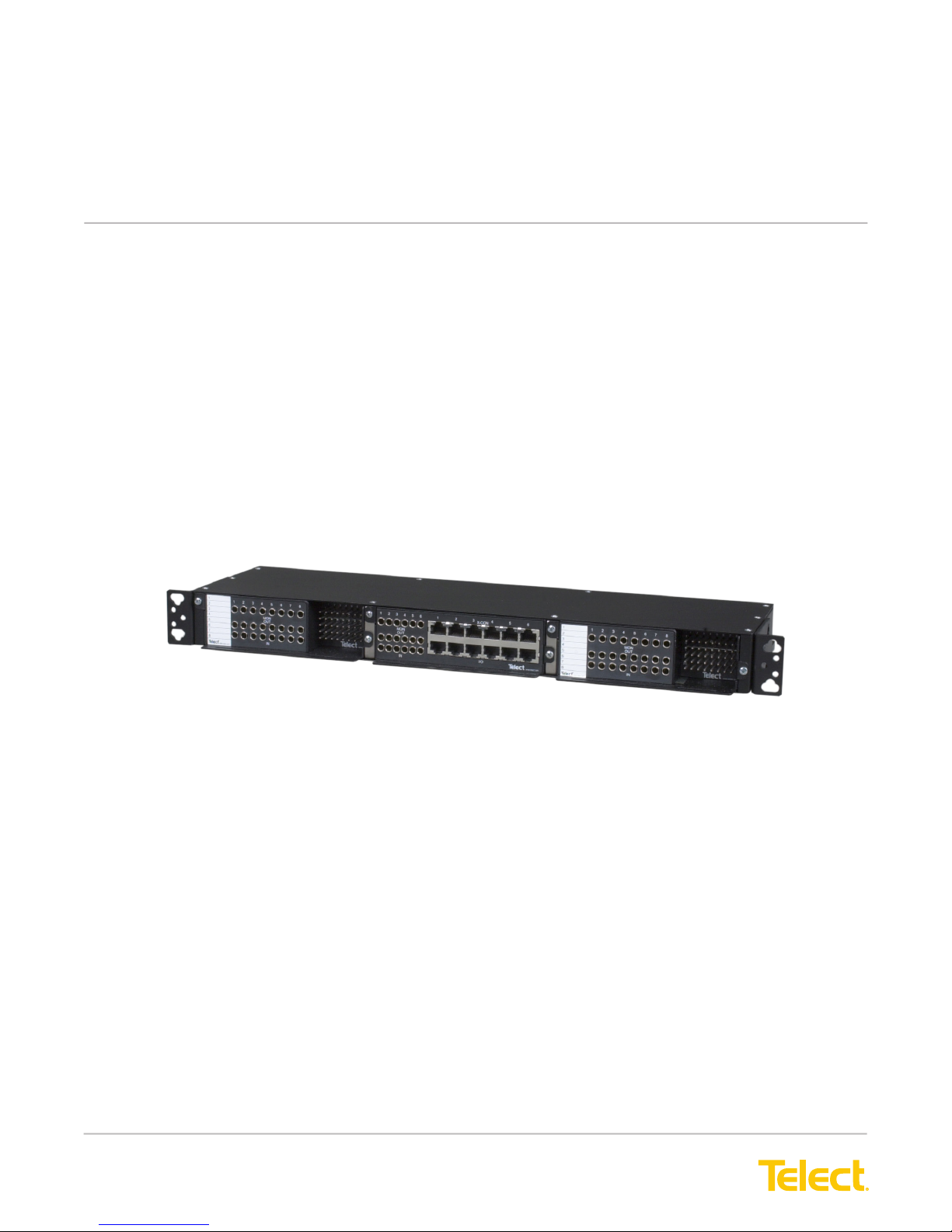
Telect’s ELF System is a small “edge” connection system for use in locations where equipment density — maximum
density with simplied monitoring — is important. The ELF System is ideal for a 3G, 4G, LTE wireless network at
a base transceiver station (BTS), customer premises, controlled environment vault, co-location, or at any remote
network terminal.
All ELF Systems consists of a chassis, wall brackets, or wall enclosures with DSX-1, DNI, DSX-3,
Fiber, and/or Ethernet/Data modules:
• ELF Chassis t equipment cabinets, 19-in. or 23-in. EIA/WECO racks, or Telect’s Wall-Mount ELF Chassis
Bracket. Each 1RU (1RU = 1.75 in.) chassis handles up to three, rear- and/or front-access ELF modules.
DSX-1, DSX-3, ber, and other ELF modules can be mixed in the same chassis.
• Single-Module ELF Wall Brackets mount to the walls. Each bracket accommodates one total front-access
ELF module
• Single-Module ELF Wall enclosures include a lockable access door. The enclosure mounts to the wall and
accommodates one rear- and/or front-access ELF module. Ideal for a Fiber ELF module.
All chassis, brackets, and enclosures include shield ground pins for ITU G.703 compliance. ELF
modules are passive devices and do not require power. All chassis, enclosure, brackets, and
modules are mainly black.
1.2 ELF Modules
The cover shows a composite of all ELF modules and mounting options.
The following identies all ELF DSX1, DSX3, ber, and signal-manager modules offered by Telect, along with
section and page references. Mounting options (chassis and wall mount) are covered in this section.
© Telect, Inc., All Rights Reserved, 124317-10 A0
1.509.926.6000 :: telect.com
1
ELF System
Copper / Fiber :: ELF Family
ELF Module Conguration ELF Model
Number
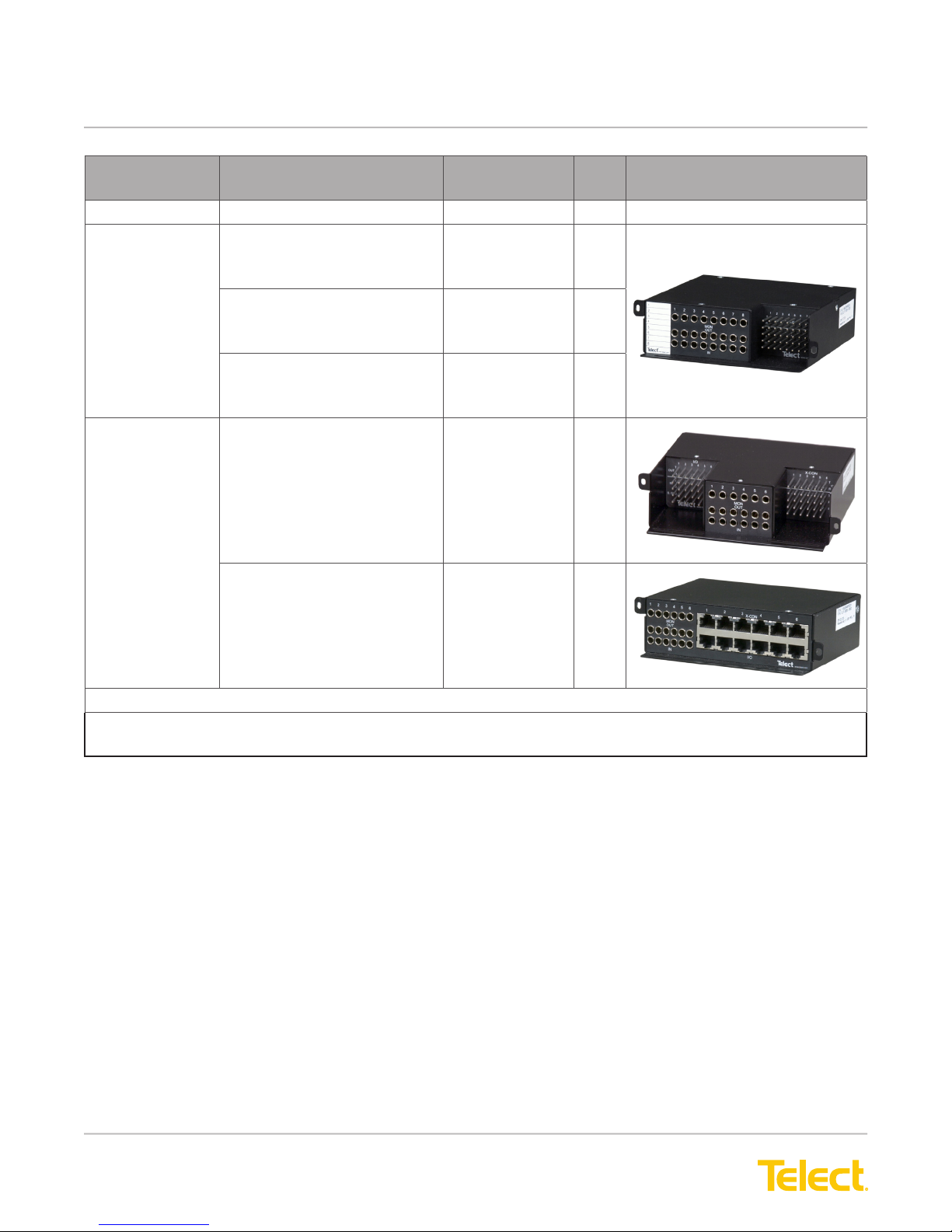
DSX-1
8-Termination REAR — Wire-Wrap I/O
FRONT — Wire-Wrap XC
• 3-Port Bantam Patch Jacks
REAR — BNC I/O
FRONT — Wire-Wrap XC
• 3-Port Bantam Patch Jacks
REAR — RJ48C I/O
FRONT — Wire-Wrap XC
• 3-Port Bantam Patch Jacks
6-Termination
(See Note.)
TOTAL FRONT ACCESS —
• Wire-Wrap I/O
• Wire-Wrap XC
• 3-Port Bantam Patch Jacks
TOTAL FRONT ACCESS —
• RJ48C I/O
• RJ48C XC
• 3-Port Bantam
Patch Jacks
ELF-1008-1100 17
ELF-1008-1200 19
ELF-1008-1800 21
ELF-3006-1100 23
ELF-3006-1800 24
Page Illustration
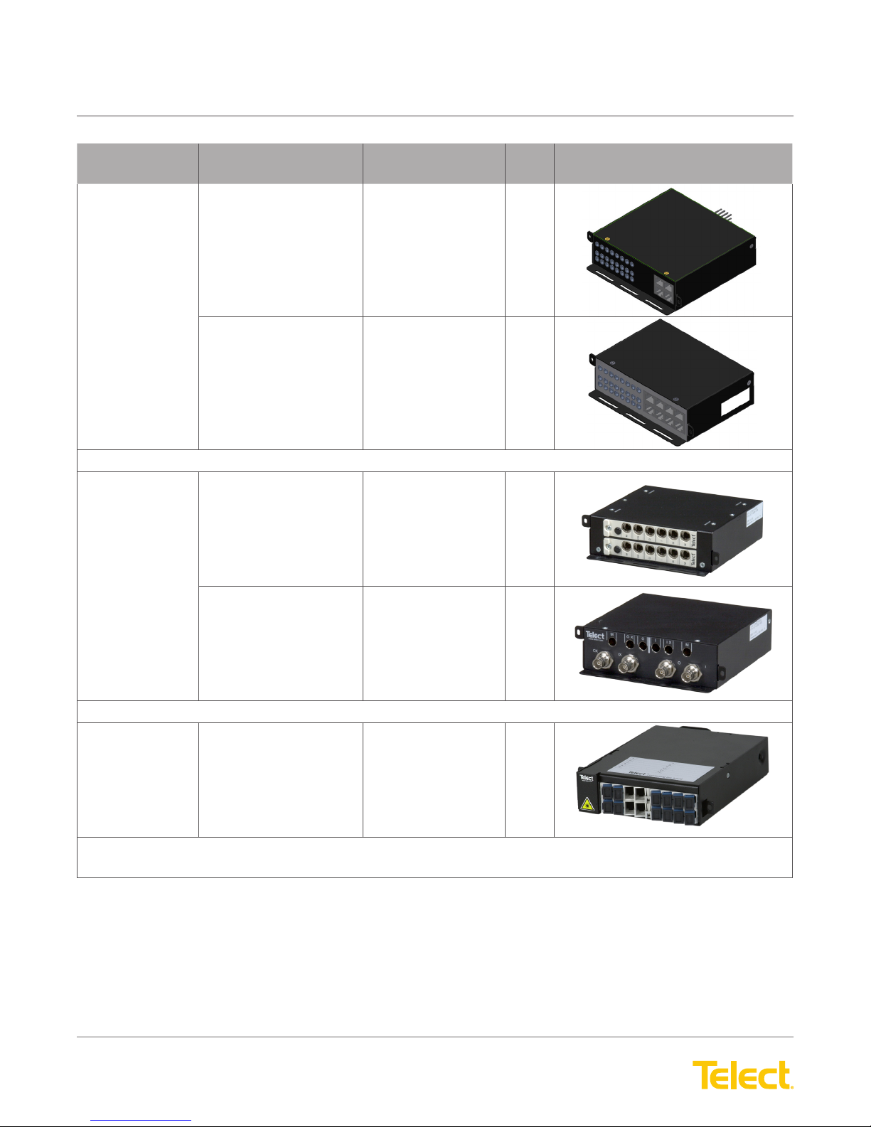
DNI-1
NOTE: All DS1 and DS3 Total Front Access and 12x4 Alarm Pin Block ELF Modules t Telect’s ELF
Wall Bracket (ELF-000-0600).
© Telect, Inc., All Rights Reserved, 124317-10 A0
1.509.926.6000 :: telect.com
2
ELF System
Copper / Fiber :: ELF Family
ELF Module Conguration ELF Model
Number
4-Circuit
Interconnect
DSX-3
2-Termination
1-Termination
(See Note.)
REAR —
• Wire-Wrap NE1 I/O
FRONT —
• RJ48C NE2 I/O
• 3-Port Bantam
Patch Jacks for all NEs
TOTAL FRONT
ACCESS(See Note.) —
• RJ48C NE1 I/O
• RJ48C NE2 I/O
• 3-Port Bantam
Patch Jacks for all NEs
REAR —
• BNC I/O & XC
FRONT —
• 6-Port Mini-WECO
Jacks
ELF-9704-1119 25
ELF-3004-1800 27
ELF-3206-1200 29
Page Illustration
TOTAL FRONT AC-
CESS —
• BNC I/O & XC
• 6-Port Mini-WECO
Jacks
Fiber
12-Termination
Patch
NOTE: All DS1 and DS3 Total Front Access and 12x4 Alarm Pin Block ELF Modules t Telect’s ELF
Wall Bracket (ELF-000-0600).
REAR —
• Fiber Jumpers from
NEs
FRONT —
• Fiber Adapters
ELF-3206-1900 31
ELF-PC12-SC00
ELF-PC12-FC00
33
© Telect, Inc., All Rights Reserved, 124317-10 A0
1.509.926.6000 :: telect.com
3
ELF System
Copper / Fiber :: ELF Family
ELF Module Conguration ELF Model
Number
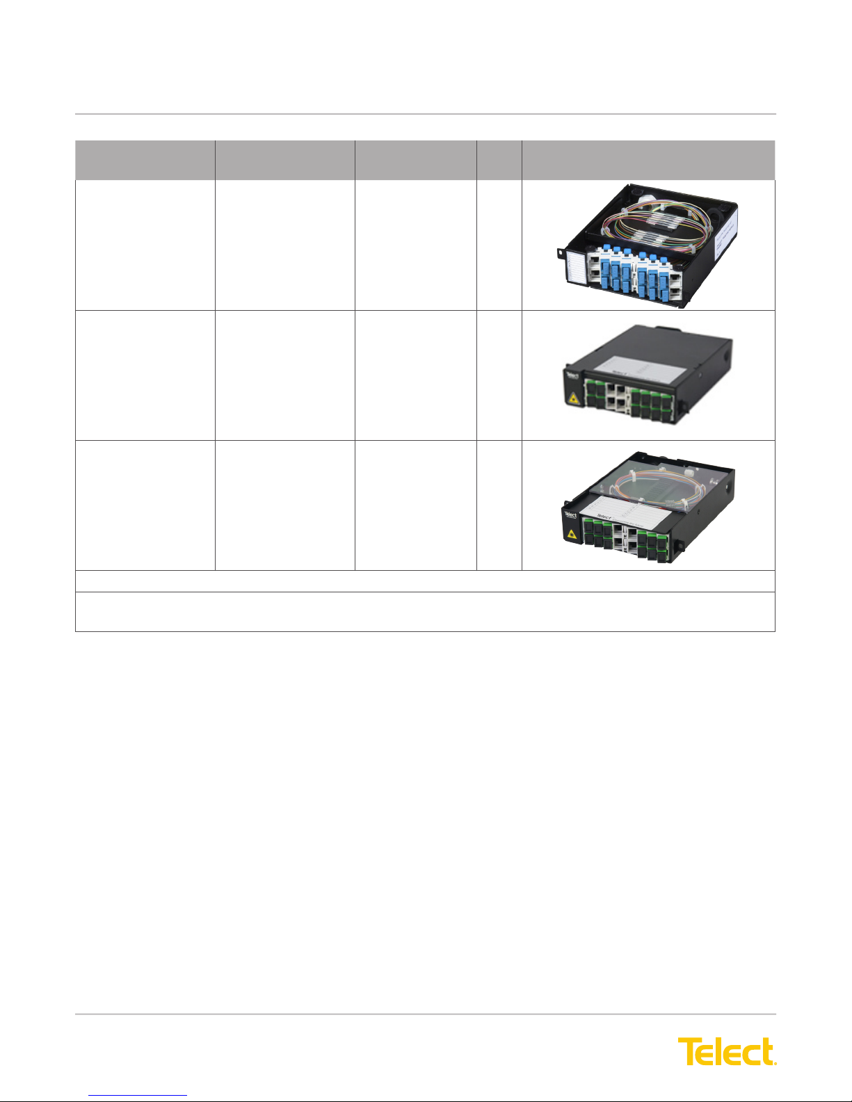
12-Termination
Splice/
Patch
12-Termination
SC-APC
Patch Module
12-Termination
SC/APC
Patch and
Splice Module
REAR —
• Subunit Entrance
FRONT —
• Fiber Adapters
REAR –
• Fiber Jumpers
from NEs
FRONT –
• Fiber Adapters
REAR –
• Subunit Entrance
FRONT –
• Fiber Adapters
ELF-SP12-SCPT
ELF-SP12-FCPT
ELF-PC12-SA00 33
ELF-SP12-SAPT 33
Page Illustration
34
General Purpose Signal Management
NOTE: All DS1 and DS3 Total Front Access and 12x4 Alarm Pin Block ELF Modules t Telect’s ELF
Wall Bracket (ELF-000-0600).
© Telect, Inc., All Rights Reserved, 124317-10 A0
1.509.926.6000 :: telect.com
4
ELF System
Copper / Fiber :: ELF Family
ELF Module Conguration ELF Model
Number
16-Circuit
Patch
12 x 4 Alarm
Pin Block
(See Note.)
REAR —
• 16, RJ45Cs
FRONT —
• 16, RJ45Cs
REAR —
• 16 IDC
Punch-Down Blocks
FRONT —
• 16, RJ45s
Bulkhead-Style Pin
Block
ELF-9716-1900 38
ELF-9716-1700 39
ELF-0005-0001 40
Page Illustration
REAR
FRONT
NOTE: All DS1 and DS3 Total Front Access and 12x4 Alarm Pin Block ELF Modules t Telect’s ELF
Wall Bracket (ELF-000-0600).
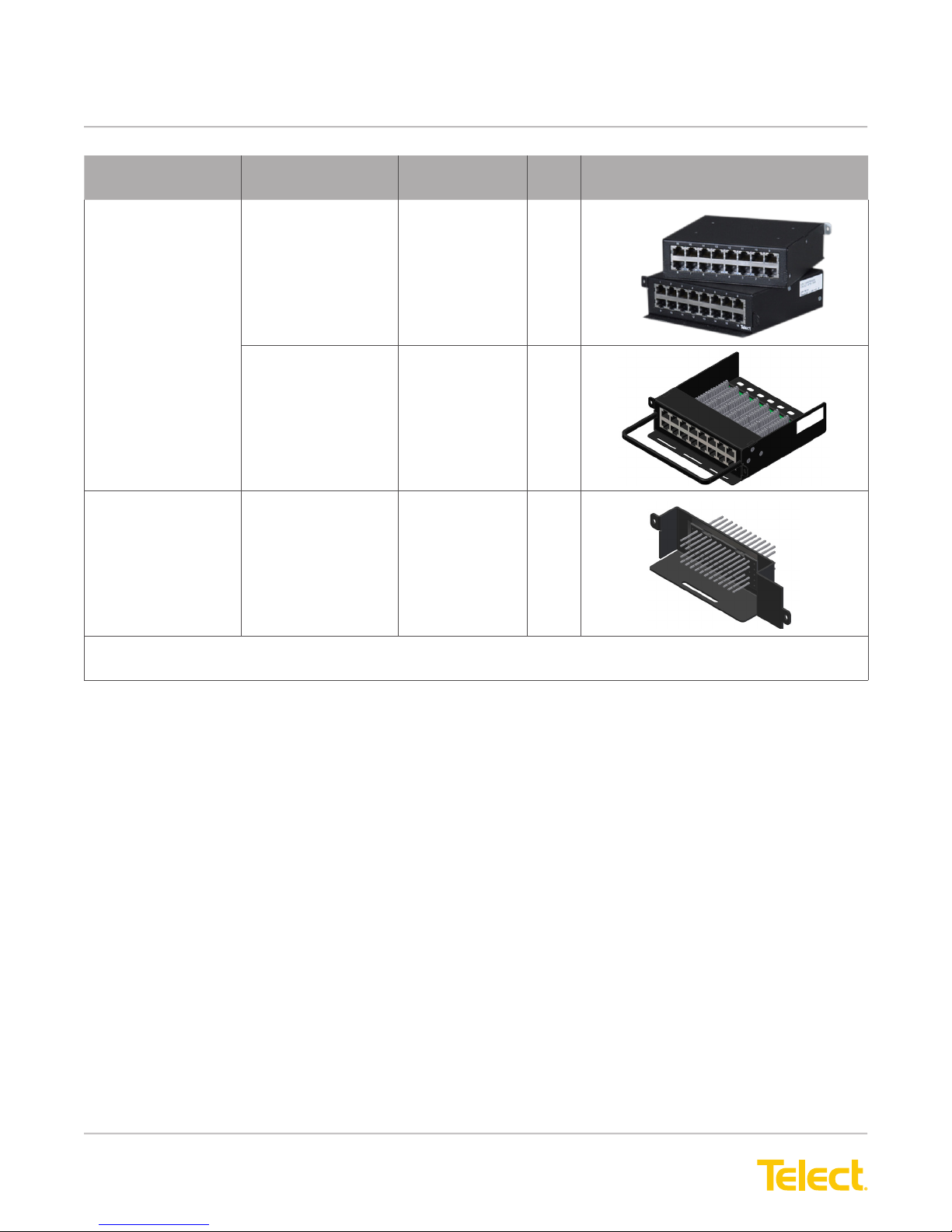
1.3 ELF Mounting Options
1.3.1 ELF Chassis (Model ELF-0000-2400)
• High-density 1RU chassis accommodates three ELF modules.
• Fully enclosed environment provides robust RF protection.
• Reversible mounting brackets available for 19-in. or 23-in. EIA/WECO racks. (Rack-mounting hardware
included.) Chassis brackets also t Telect’s Wall-Mount ELF Chassis Bracket.
• Total termination capacity per chassis:
− 18 or 24 DSX-1
− 12 DNI
− 3 or 6 DSX-3
− 36 ber splices/patches
− 48 RJ45C-to-RJ45C patches
− 36 alarm interconnects
© Telect, Inc., All Rights Reserved, 124317-10 A0
1.509.926.6000 :: telect.com
5
ELF System
Copper / Fiber :: ELF Family
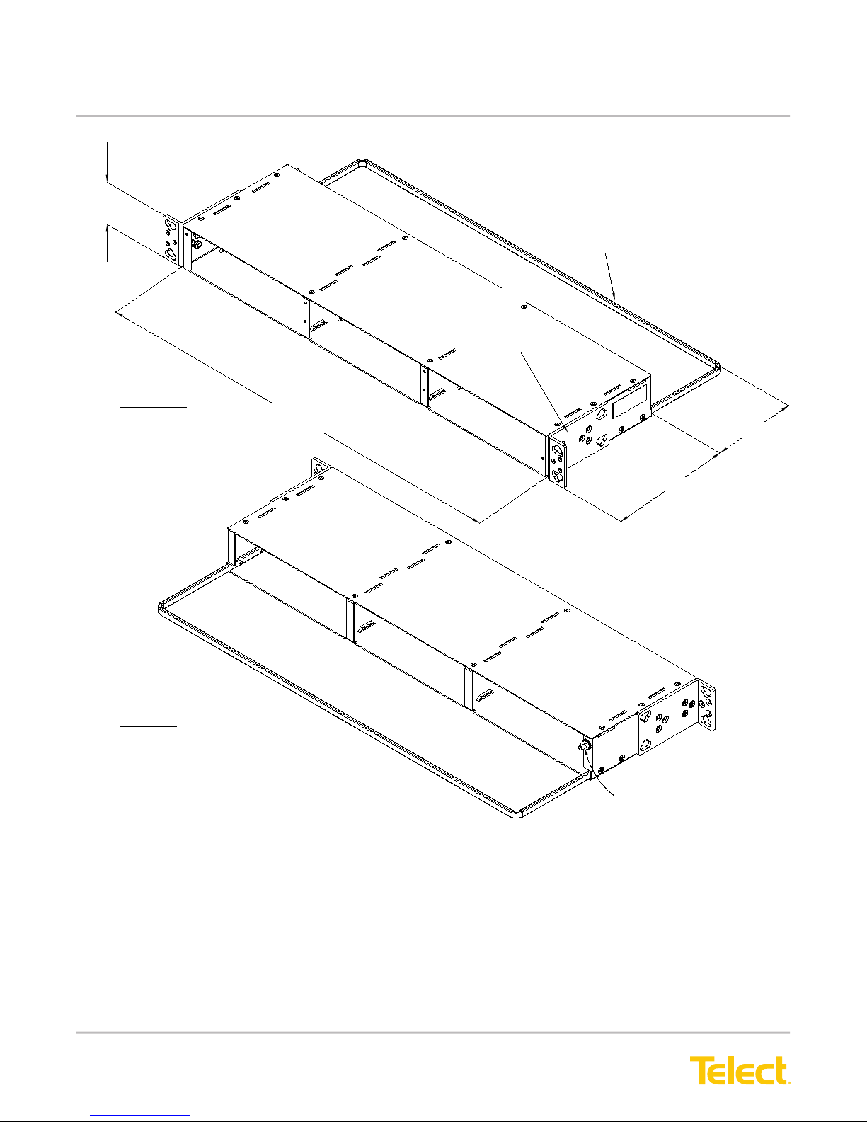
1.73 (44.0)
FRONT VIEW
17.25 (438.2)
Note: Dimensions are in in. (mm)
Removable Cable
Tie-Down Bar
Reversible Rack Brackets
Fit 19-in. or 23-in., EIA- or
WECO-Spaced Racks. Brackets
can be Positioned for Panel Flush
or 1-in. Extended Mounting.
3.5 (88.9)
REAR VIEW
5.00 (127.0)
#8-32 Ground Stud and KEPS Nut
Figure 1 - ELF Chassis Mounting Options
© Telect, Inc., All Rights Reserved, 124317-10 A0
1.509.926.6000 :: telect.com
6
ELF System
Copper / Fiber :: ELF Family
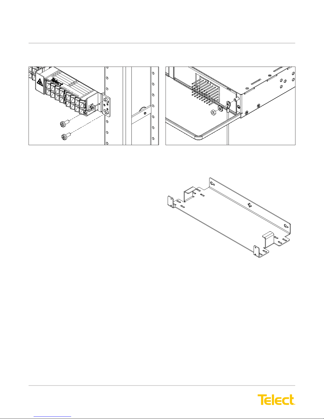
The following illustrations show a typical installation.
Figure 2 - Installing ELF Chassis on a Rack
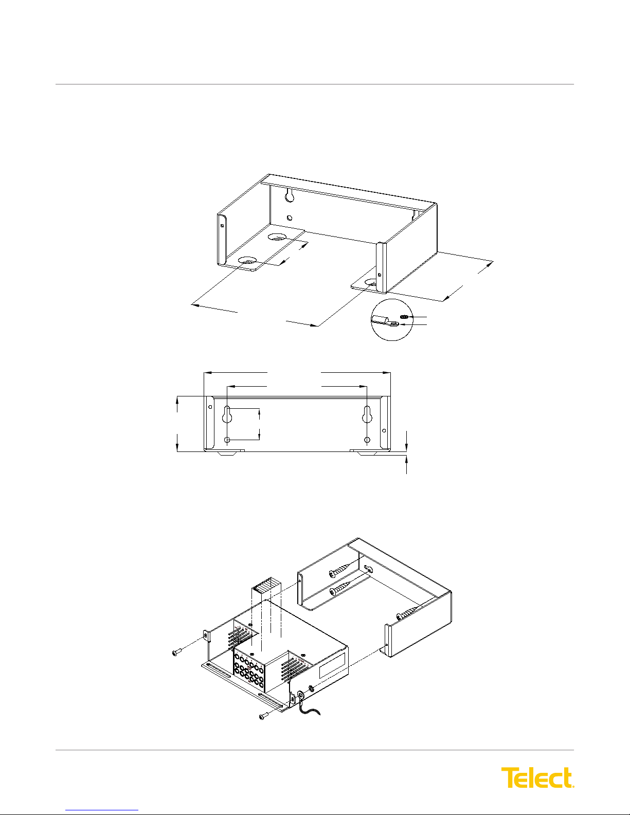
1.3.2 Wall-Mount ELF Chassis Bracket (ELF-0000-0900)
Telect’s Wall-Mount ELF Chassis Bracket is designed
to hold one ELF Chassis (ELF-0000-2400) against a
wall or side of a cabinet. The chassis bracket allows
an ELF chassis with either rear- and/or front-access
modules to either extend from a wall or cabinet using
a minimum wall “footprint” or to hug the wall or cabinet
with a minimum prole. Wall-mounting hardware is
not included.
Figure 3 - Grounding an ELF Chassis
Figure 4 - Bracket
© Telect, Inc., All Rights Reserved, 124317-10 A0
1.509.926.6000 :: telect.com
7

ELF System
Copper / Fiber :: ELF Family
5.30
(134.6)
3.30
(83.8)
0.91 (23.0)
1.25
(31.8)
0.50 (12.7)
0.75 (19.0)
18.71 (475.2)
16.00 (406.4)
3.00 (76.2)
0.25 (6.35)
Outline of ELF Chassis
8.00 (203.2)
0.50 (12.7)
5.00 (127.0)
0.25 (6.35)
0.875 (22.2)
16.00 (406.4)
19.77 (502.2)
18.31 (465.1)
Figure 5 - Wall-Mount ELF Chassis Bracket Dimensions
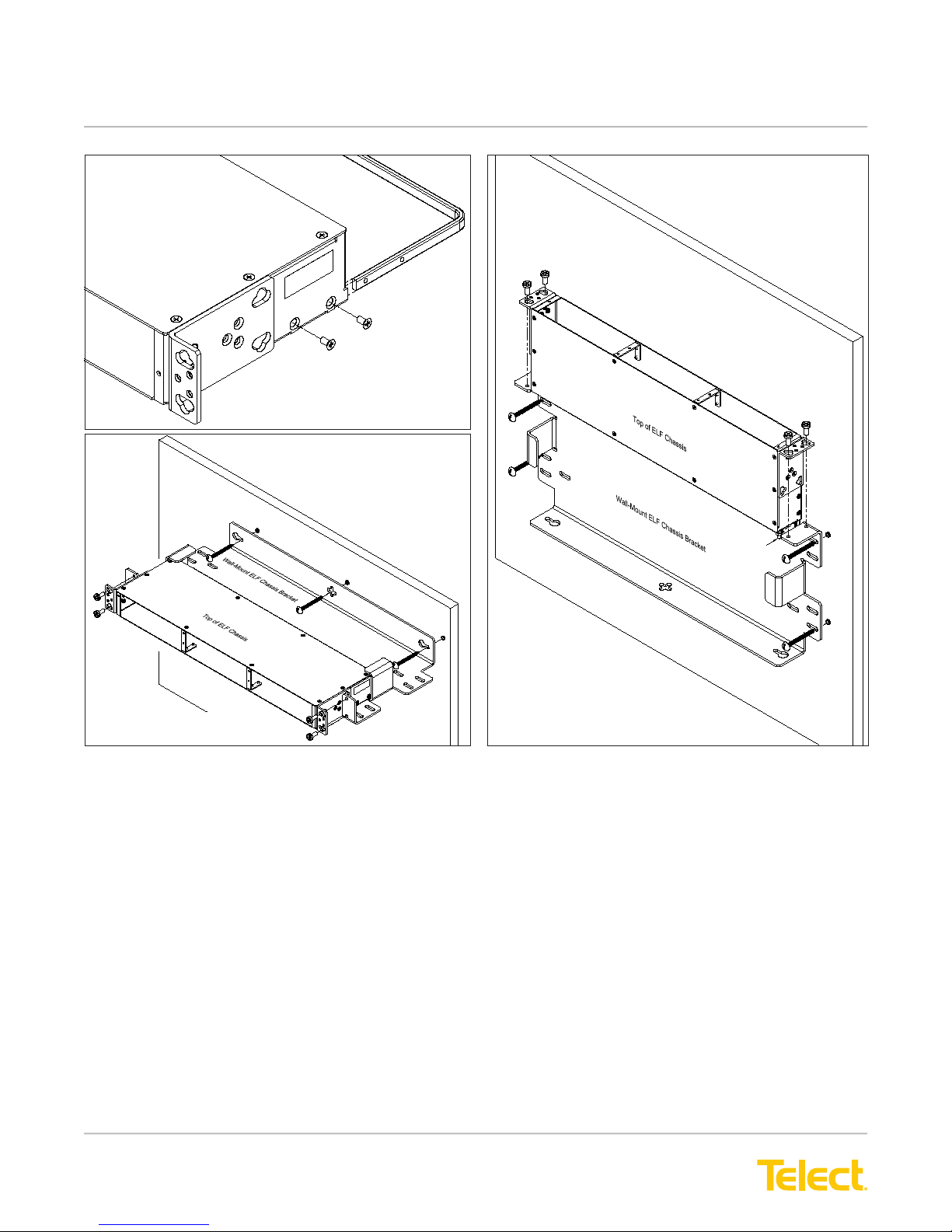
Typical wall installations are shown in the following illustrations. Telect recommends that the tie bar on the rear
of the ELF Chassis be removed when installing in the Wall-Mount ELF Chassis Bracket. Also, when installing
rear access ELF modules, Telect recommends including a minimum 2-ft (600-mm) service loop for any cabling or
wiring intended for the rear of the ELF module(s). Don’t forget to install a ground wire on the ELF Chassis, as
shown on Page 7.
© Telect, Inc., All Rights Reserved, 124317-10 A0
1.509.926.6000 :: telect.com
4.30
(109.2)
8.00
(203.2)
0.95 (24.1)
2.03 (51.5)
8
ELF System
Copper / Fiber :: ELF Family
Removing Tie Bar
Rear Tie Bar
Hugging a Wall
Extending from a Wall
Figure 6 - Wall-Mount ELF Chassis Bracket Installation
ELF Chassis
GND Stud
© Telect, Inc., All Rights Reserved, 124317-10 A0
1.509.926.6000 :: telect.com
9
ELF System
Copper / Fiber :: ELF Family
1.3.3 ELF Wall Bracket (Model ELF-0000-0600)
Wall-mount bracket for one, total front access ELF module (ELF-3006-1100, ELF-3006-1800, ELF-3004-1800, or
ELF -0005-0001). Wall-mounting hardware is not included.
Note: Dimensions are in in. (mm)
2.25 (57.2)
4.00 (101.6)
4.50 (114.3)
6.00 (152.4)
4.50 (114.3)
1.78
(54.2)
1.00 (25.4)
Figure 7 - ELF Wall Bracket Dimensions
The following illustration shows a typical installation.
#4 Lockwasher
#4 Lug for 16-14 AWG
Grounding Hardware Included
0.12
(3.0)
Figure 8 - Typical ELF Wall Bracket Installation
© Telect, Inc., All Rights Reserved, 124317-10 A0
1.509.926.6000 :: telect.com
10

ELF System
Copper / Fiber :: ELF Family
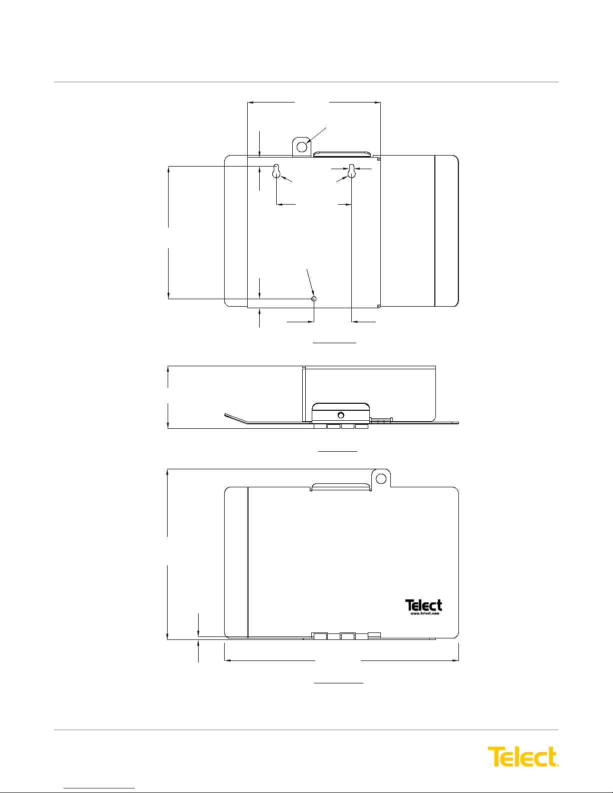
1.3.4 ELF Lockable Wall-Mount Enclosure (Model ELF-0000-0800)
Wall-mount enclosure, designed initially for one ber
ELF module, accommodates any rear-and/or
front-access ELF module. Model ELF-000-0800
includes a lockable access door, ideal for co-locations.
Wall-mounting and grounding hardware are not included.
The following illustration shows a typical installation.
Ground Strap & Lock Washer
are not supplied
ELF Module
(Typical)
Screws are supplied with ELF Module
Mounting screws are not supplied
Figure 9 - ELF Lockable Wall-Mount Enclosure
© Telect, Inc., All Rights Reserved, 124317-10 A0
1.509.926.6000 :: telect.com
11
ELF System
Copper / Fiber :: ELF Family
135 (5.31)
Note: Dimensions are in mm (in.)
134
(5.28)
63.5
(2.50)
9.0 (0.35)
9.4 (0.37)
10 (0.39) Dia.
4.6 (.18)
7.6 (0.3) Dia.
76.2 (3.00)
4.6 (.18) Dia.
38.1 (1.5)
REAR VIEW
(ROTATED)
172.9
(6.81)
TOP VIEW
3.00
(0.12)
236.79 (9.32)
FRONT VIEW
Figure 10 - ELF Lockable Wall-Mount Dimensions
© Telect, Inc., All Rights Reserved, 124317-10 A0
1.509.926.6000 :: telect.com
12
 Loading...