

Page 1

User Manual
TDS1000- and TDS2000-Series
Digital Storage Oscilloscope
071-1064-00
This document supports firmware version
FV:v1.00 and above.
www.tektronix.com
Page 2

Copyright © Tektronix, Inc. All rights reserved.
Tektronix products are cove red by U.S. and foreign patents, issued and
pending. Information in this publication supercedes that in all previously
published material. Specifications and price change privileges reserved.
Tektronix, Inc., P.O. Box 500, Beaverton, OR 97077
TEKTRONIX and TEK are registered trademarks of Tektronix, Inc.
Page 3

WARRANTY SUMMARY
(TDS1000- and TDS2000-Series Digital Storage Oscilloscope)
Tektronix warrants that the products that it manufactures and sells will be free from defects
in materials and workmanship for a period of three (3) years from the date of shipment
from an authorized Tektronix distributor. If a product or CRT proves defective within the
respective period, Tektronix will provide repair or replacement as described in the complete
warranty statement.
To arrange for service or obtain a copy of the complete warranty statement, please contact
your nearest Tektronix sales and service office.
EXCEPT AS PROVIDED IN THIS SUMMARY OR THE APPLICABLE WARRANTY
STATEMENT, TEKTRONIX MAKES NO WARRANTY OF ANY KIND, EXPRESS
OR IMPLIED, INCLUDING WITHOUT LIMITATION THE IMPLIED WARRANTIES
OF MERCHANTABILITY AND FITNESS FOR A PARTICULAR PURPOSE. IN NO
EVENT SHALL TEKTRONIX BE LIABLE FOR INDIRECT, SPECIAL OR
CONSEQUENTIAL DAMAGES.
Page 4

WARRANTY SUMMARY
(P2200 Probe)
Tektronix warrants that the products that it manufactures and sells will be free from defects
in materials and workmanship for a period of one (1) year from the date of shipment. If a
product proves defective within the respective period, Tektronix will provide repair or
replacement as described in the complete warranty statement.
To arrange for service or obtain a copy of the complete warranty statement, please contact
your nearest Tektronix sales and service office.
EXCEPT AS PROVIDED IN THIS SUMMARY OR THE APPLICABLE WARRANTY
STATEMENT, TEKTRONIX MAKES NO WARRANTY OF ANY KIND, EXPRESS
OR IMPLIED, INCLUDING WITHOUT LIMITATION THE IMPLIED WARRANTIES
OF MERCHANTABILITY AND FITNESS FOR A PARTICULAR PURPOSE. IN NO
EVENT SHALL TEKTRONIX BE LIABLE FOR INDIRECT, SPECIAL OR
CONSEQUENTIAL DAMAGES.
Page 5

Table of Contents
General Safety Summary v............................
Preface vii............................................
Help System ix........................................
Conventions xi........................................
Product End-of-Life Handling xii..........................
Contacting Tektronix xiii.................................
Getting Started 1.....................................
General Features 2....................................
Installation 4.........................................
Power Cord 4......................................
Security Loop 4....................................
Functional Check 5....................................
Probe Safety 6........................................
Probe Check Wizard 7.................................
Manual Probe Compensation 8...........................
Probe Attenuation Setting 9.............................
Self Calibration 10.....................................
Understanding Oscilloscope Functions 11.................
Setting Up the Oscilloscope 12...........................
Using Autoset 12....................................
Saving a Setup 12...................................
Recalling a Setup 12.................................
Default Setup 13....................................
Triggering 13.........................................
Source 14..........................................
Types 15..........................................
Modes 15..........................................
Coupling 15........................................
Position 16.........................................
Slope and Level 16..................................
TDS1000/2000-Series Digital Oscilloscope User Manual
i
Page 6

Table of Contents
Acquiring Signals 17...................................
Acquisition Modes 17................................
Time Base 18......................................
Scaling and Positioning Waveforms 18.....................
Vertical Scale and Position 18.........................
Horizontal Scale and Position; Pret rigger Inform ation 19....
Taking Measurements 24................................
Graticule 24........................................
Cursors 25.........................................
Automatic 25.......................................
Operating Basics 27...................................
Display Area 28.......................................
Message Area 31....................................
Using the Menu System 32...............................
Vertical Controls 34....................................
Horizontal Controls 35..................................
Trigger Controls 36.....................................
Menu and Control Buttons 38............................
Connectors 39.........................................
Application Examples 41...............................
Taking Simple Measurements 42..........................
Using Autoset 42....................................
Taking Automatic Measurements 43....................
Measuring Two Signals 46............................
Taking Cursor Measurements 48..........................
Measuring Ring Frequency 48.........................
Measuring Ring Amplitude 49.........................
Measuring Pulse Width 50............................
Measuring Rise Time 51..............................
Analyzing Signal Detail 54..............................
Looking at a Noisy Signal 54..........................
Separating the Signal from Noise 55....................
Capturing a Single-Shot Signal 56.........................
Optimizing the Acquisition 57.........................
Measuring Propagation Delay 58..........................
ii
TDS1000/2000-Series Digital Oscilloscope User Manual
Page 7

Table of Contents
Triggering on a Specific Pulse Width 60....................
Triggering on a Video Signal 62...........................
Triggering on Video Fields 63.........................
Triggering on Video Lines 64..........................
Using the Window Function to See Waveform Details 66....
Analyzing a Differential Communication Signal 68...........
Viewing Impedance Changes in a Network 70...............
Reference 73.........................................
Acquire 74............................................
Autoset 79............................................
Sine Wave 81......................................
Square Wave or Pulse 82.............................
Video Signal 83.....................................
Cursors 84............................................
Default Setup 85.......................................
Display 86............................................
Help 89..............................................
Horizontal 90.........................................
Math 93..............................................
Measure 94...........................................
Print 96..............................................
Probe Check 96........................................
Save/Recall 97........................................
Trigger Controls 99.....................................
Utility 110.............................................
Vertical 112............................................
Math FFT 115.........................................
Setting Up the Time-Domain Waveform 116.................
Displaying the FFT Spectrum 118..........................
Selecting an FFT Window 120.............................
Magnifying and Positioning an FFT Spectrum 124.............
Measuring an FFT Spectrum Using Cursors 126...............
TDS1000/2000-Series Digital Oscilloscope User Manual
iii
Page 8

Table of Contents
TDS2CMA Communications Module 127..................
Installing and Removing an Extension Module 127............
Checking Module Installation 130..........................
Troubleshooting Module Installation 130....................
Sending Screen Data to an External Device 131...............
Setting Up and Testing the RS-232 Interface 134..............
Transferring Binary Data 141...........................
Reporting RS-232 I/O Errors 141........................
Setting Up and Testing the GPIB Interface 143................
Command Entry 150.....................................
Appendix A: Specifications 151...........................
Appendix B: Accessories 169.............................
Appendix C: General Care and Cleaning 173...............
Appendix D: Default Setup 175...........................
Appendix E: GPIB and RS-232 Interfaces 179..............
Index 181.............................................
iv
TDS1000/2000-Series Digital Oscilloscope User Manual
Page 9

General Safety Summary
Review the following safety precautions to avoid injury and prevent
damage to this product or any products connected to it. To avoid
potential hazards, use this product only as specifi ed.
Only qualified personnel should perform service procedures.
To Avoid Fire or Personal Injury
Use Proper Power Cord. Use only the power cord specified for this
product and certified for the country of use.
Connect and Disconnect Properly. Do not connect or disconnect probes
or test leads while they are connected to a voltage source.
Ground the Product. This product is grounded through the grounding
conductor of the power cord. To avoid el ectric shock, the grounding
conductor must be connected to eart h ground. Before making
connections to the input or output terminals of the product, ensure
that the product is properly grounded.
Connect the Probe Properly. The probe ground lead is at ground
potential. Do not connect the ground lead to an elevated voltage.
Observe All Terminal Ratings. To avoid fire or shock hazard, observe all
ratings and marking on the product. Consult the product manual for
further ratings information before making connections to the product.
Do Not Operate Without Covers. Do not operate this product with
covers or panels removed.
Use Proper Fuse. Use only the fuse type and rating specified for this
product.
Avoid Exposed Circuitry. Do not touch exposed connections and
components when power is present.
Do Not Operate With Suspected Failures. If you suspect there is damage
to this product, have it inspected by qualified service personnel.
Provide Proper Ventilation. Refer to the manual’s installation
instructions for details on installing the product so it has proper
ventilation.
TDS1000/2000-Series Digital Oscilloscope User Manual
v
Page 10
General Safety Summary
Do Not Operate in Wet/Damp Conditions.
Do Not Operate in an Explosive Atmosphere.
Keep Product Surfaces Clean and Dry.
Safety Terms and Symbols
Terms in This Manual. These terms may appear in this manual:
WARNING. Warning statements identify c ondi tions or practices that
could result in injury or loss of life.
CAUTION. Caution statements identify conditions or practices that
could result in damage to this product or other property.
Terms on the Product. These terms may appear on the product:
DANGER indicates an injury hazard immediately accessible as you
read the marking.
WARNING indicates an injury hazard not immediately accessible as
you read the marking.
CAUTION indicates a hazard to property including the product.
Symbols on the Product. These symbols may appear on the product:
Protective Ground
(Earth) Terminal
Mains Disconnected
OFF (Power)
Measurment
Ground Terminal
Mains Connected
ON (Power)
CAUTION
Refer to Manual
Measurment
Input Terminal
vi
TDS1000/2000-Series Digital Oscilloscope User Manual
Page 11

Preface
This manual contains operating information for the TDS1000-Series
and TDS2000-Series Digital Storage Oscilloscopes. The manual
consists of the following chapters:
H The Getting Started chapter briefly describes features of the
H The Understanding Oscilloscope Functions chapter describes
H The Operating Basics chapter covers operating principles of the
H The Application Examples chapter includes examples of a wide
oscilloscope and provides installation instructions.
basic operations and functions of the oscilloscope: setting up the
oscilloscope, triggering, acquiring data, scaling and positioning
waveforms, and taking measurements.
oscilloscope.
variety of measurements to give you ideas on how to solve your
own measurement problems.
H The Reference chapter describes the selections or available range
of values for each option.
TDS1000/2000-Series Digital Oscilloscope User Manual
vii
Page 12

Preface
H The Math FFT chapter contains detai led i nformation about how
to use the Math FFT funct ion.
H The TDS2CMA Communications Module chapter describes this
optional module and how to set up the RS-232, GPIB, and
Centronics ports to use the oscilloscope with external devices,
such as printers and computers.
H The Appendix A: Specifications chapter includes electrical,
environmental, and physical spec ifications for t he oscilloscope,
as well as certifications and compliances.
H The Appendix B: Accessories chapter briefly describes standard
and optional accessories.
H The Appendix C: General Care and Cleaning chapter describes
how to take care of the oscilloscope.
H The Appendix D: Default Setup chapter contains a list of the
menus and controls with the default (factory) settings that are
recalled when you push the DEFAULT SETUP front-panel
button.
H The Appendix E: GPIB and RS-232 Interfaces chapter compares
the two protocols to help you de cide which one to use.
viii
TDS1000/2000-Series Digital Oscilloscope User Manual
Page 13

Help System
The oscilloscope has a Help system with topics that cover all the
features of the oscilloscope. You can use the Help system to display
several kinds of information:
H General information about understanding and using the
oscilloscope, such as Using the Menu System.
H Information about specific menus and controls, such as the
Vertical Position Control.
H Advice about problems you may face while using an oscillo-
scope, such as Reducing Noise.
The Help system provides three ways for you to find the information
you need: context-sensitive, hyperlinks, and an index.
Preface
Context-Sensitive
The oscilloscope displays information about the last menu displayed
on the screen when you push the HELP front-panel button. The
HELP SCROLL LED lights under the HORIZONTAL POSITION
knob to indicate the alternative function of the knob. If the topic uses
more than one page, turn the HELP SCROLL knob to move from
page to page within the topic.
TDS1000/2000-Series Digital Oscilloscope User Manual
ix
Page 14

Preface
Hyperlinks
Most of the help topics contain phrases marked with angle bracke ts,
such as < Autoset>. These are links to ot her topi cs. Turn the HELP
SCROLL knob to move the highlight from one link to another. Push
the Show Topic option button to display the topic corresponding to
the highlighted link. Push the Back option button to return to the
previous topic.
Index
Push the front--panel HELP button, then push the Index option
button. Push the Page Up or Page Down option buttons until you find
the index page that contains the topic you want to view. Turn the
HELP SCROLL knob to hi ghlight a help topic. Push the Show Topic
option button to display the topic.
NOTE. Push the Exit option button or any menu button to remove the
Help text from the screen and return to displaying waveforms.
x
TDS1000/2000-Series Digital Oscilloscope User Manual
Page 15
Conventions
This manual uses the following conventions:
H Front-panel buttons, knobs and connectors appear in all
uppercase letters. For example: HELP, PRINT.
H Menu options appear with the first letter of each word in upper
case. For example: Peak Detect, Window Zone.
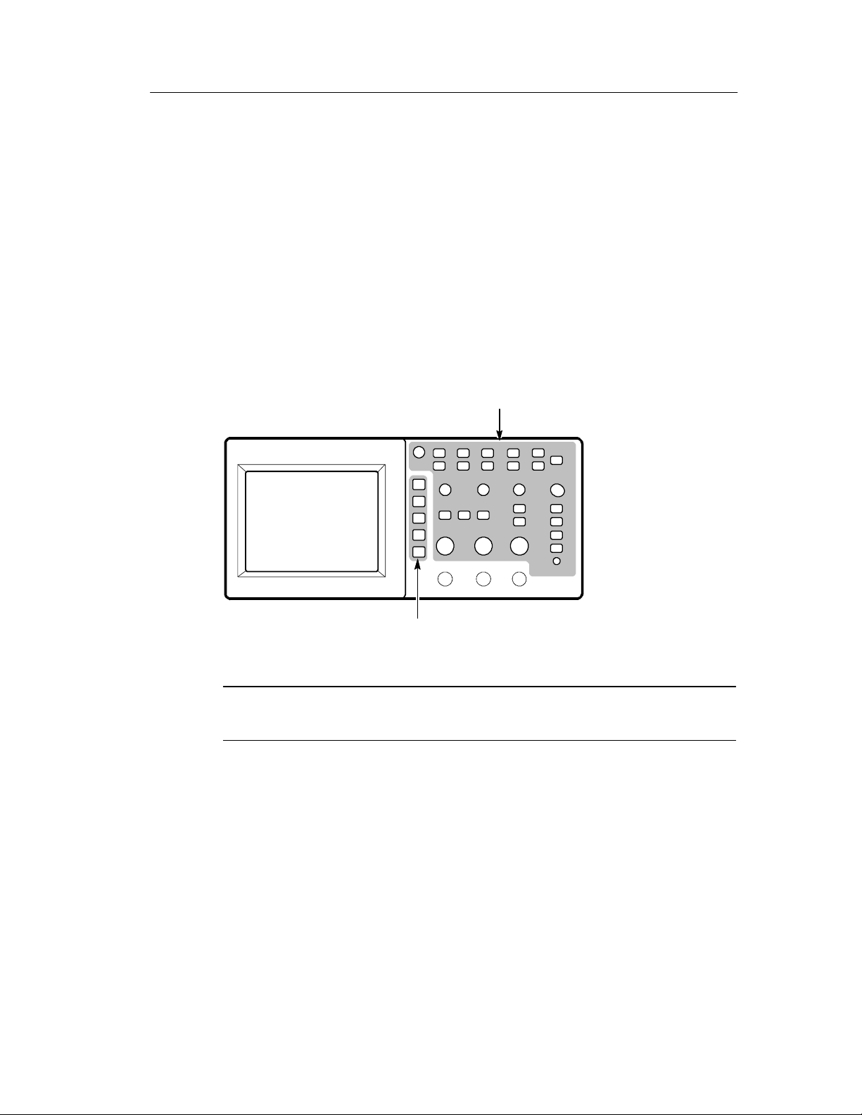
Preface
Front-panel buttons and
knob labels — All upper case
Option buttons — First letter of
each word on screen is upper case
NOTE. Option buttons can also be called screen buttons, side-menu
buttons, bezel buttons, or soft keys.
H The
" delimiter separates a series of button pushes. For example,
UTILITY
" Options " RS-232 means that you push the
UTILITY button, then push the Options option button, and then
push the RS-232 option button.
TDS1000/2000-Series Digital Oscilloscope User Manual
xi
Page 16

Preface
Product End -of-Life Handling
Components that Contain Mercury. The cold cathode fluorescent tube
located in the liquid crystal display backlight contains trace amounts
of mercury. When you are ready to reclaim the instrument, you must
properly transfer it according to local regulations concerning
mercury-containing equipment or ship the instrument to the
Tektronix Recycling Operations (RAMS). You can contact Tektronix
for the RAMS shipping address and instructions.
xii
TDS1000/2000-Series Digital Oscilloscope User Manual
Page 17

Contacting Tektronix
Phone 1-800-833-9200*
Address Tektronix, Inc.
Department or name (if known)
14200 SW Karl Braun Drive
P.O. Box 500
Beaverton, OR 97077
USA
Web site www.tektronix.com
Preface
Sales
support
Service
support
Technical
support
* This phone number is toll free in North America. After office
hours, please leave a voice mail message.
Outside North America, contact a Tektronix sales office or
distributor; see the Tektronix web site for a list of offices.
1-800-833-9200, select option 1*
1-800-833-9200, select option 2*
Email: techsupport@tektronix.com
1-800-833-9200, select option 3*
6:00 a.m. -- 5:00 p.m. Pacific time
TDS1000/2000-Series Digital Oscilloscope User Manual
xiii
Page 18

Preface
xiv
TDS1000/2000-Series Digital Oscilloscope User Manual
Page 19

Getting Started
TDS1000-Series and TDS2000-Series Digital Storage Oscilloscopes
are small, lightweight, benchtop packages that you can use to take
ground-referenced measurements.
In addition to the list of general features, this chapter describes how
to do the following tasks:
H Install your product
H Perform a brief functional check
H Perform a probe check and compensate probes
H Match your probe attenuation factor
H Use the self calibration routine
NOTE. You can select a language to di splay on the screen when you
power on the oscilloscope. At any time, you can push the UTILITY
button, and push the Language option button to select a language.
TDS1000/2000-Series Digital Oscilloscope User Manual
1
Page 20

Getting Started
General Features
The next table and bulleted list describe the general features.
Model Channels Bandwidth Sample rate Display
TDS1002 2 60 MHz 1.0 GS/s Monochrome
TDS1012 2 100 MHz 1.0 GS/s Monochrome
TDS2002 2 60 MHz 1.0 GS/s Color
TDS2012 2 100 MHz 1.0 GS/s Color
TDS2014 4 100 MHz 1.0 GS/s Color
TDS2022 2 200 MHz 2.0 GS/s Color
TDS2024 4 200 MHz 2.0 GS/s Color
H Context-sensitive Help system
H Color or monochrome LCD display
H Selectable 20 MHz bandwidth limit
H 2500 point record length for each channel
H Autoset Menu
H Probe Check Wizard
H Cursors with readouts
H Trigger frequency readout
H Eleven automatic measurements
H Waveform averaging and peak de tection
2
TDS1000/2000-Series Digital Oscilloscope User Manual
Page 21

Getting Started
H Dual time base
H Math Fast Fourier Transform (FFT)
H Pulse Width trigger capability
H Video trigger capability with line-selectable triggering
H External trigger
H Setup and waveform storage
H Variable persistence display
H RS-232, GPIB, and Centronics ports with the optional
TDS2CMA Communications Extension Module
H User interface in ten user-selectable l anguages
TDS1000/2000-Series Digital Oscilloscope User Manual
3
Page 22
Getting Started
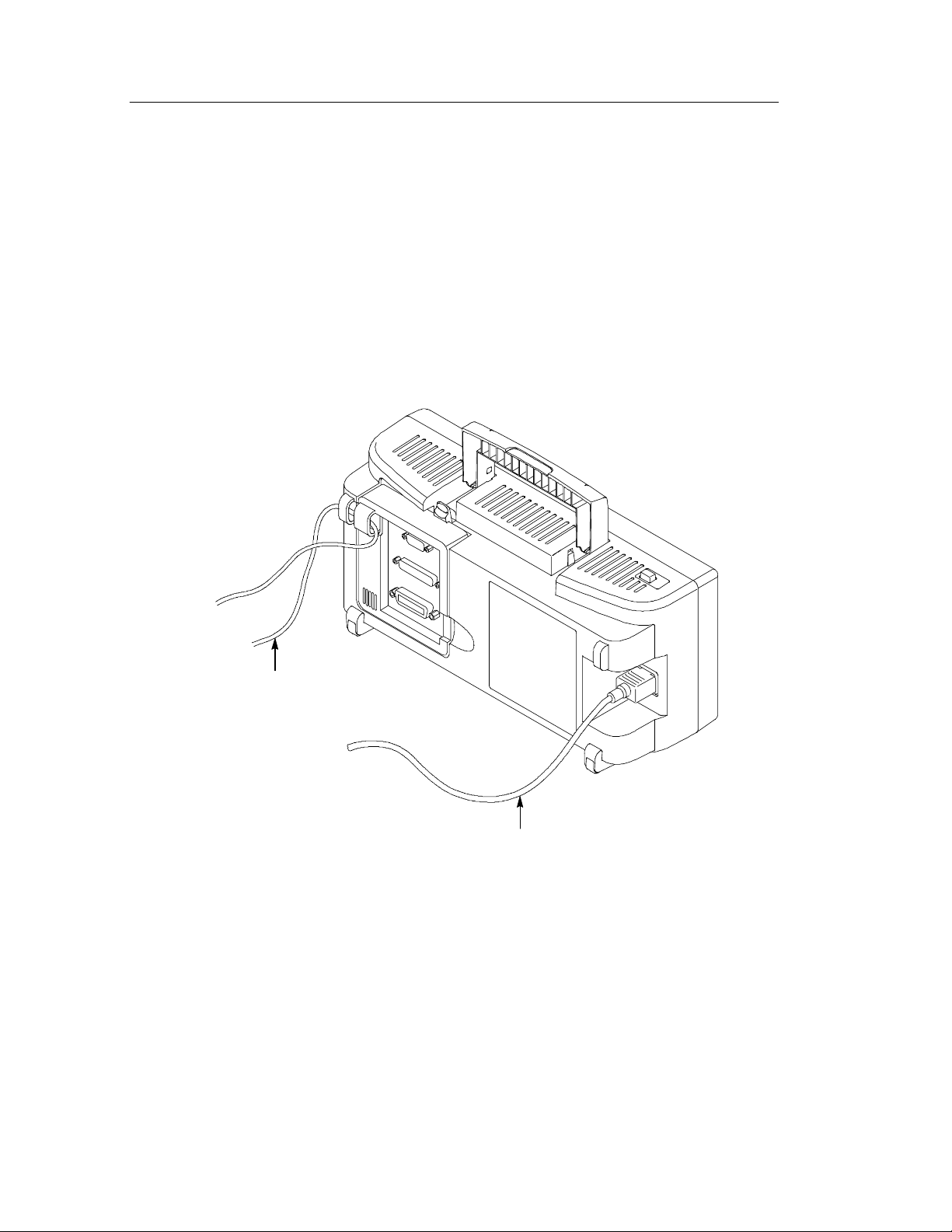
Installation
Power Cord
Use only power cords designed for your oscilloscope. Use a power
source that delivers 90 to 264 VAC
400 Hz power source, it m ust deliver 90 to 132 VAC
440 Hz. Refer to page 171 for a list of available power cords.
, 45 to 66 Hz. If you have a
RMS
, 360 to
RMS
Securing cable
Power cable
Security Loop
Use the built-in cable channels to secure both your oscilloscope and
extension module to your location.
4
TDS1000/2000-Series Digital Oscilloscope User Manual
Page 23

Functional Check
Perform this quick functional check to verify that your oscilloscope
is operating correctly.
Getting Started
ON/OFF
button
PASSED
CH 1
PROBE COMP
1. Power on the oscilloscope.
Wait until the display shows that all
power-on tests passed. Push the DEFAULT
SETUP button. The default Probe option
attenuation setting is 10X.
2. Set the switch to 10X on the P2200 probe
and connect the probe to channel 1 on the
oscilloscope. To do this, align the slot in
the probe connector with the key on the
CH 1 BNC, push to connect, and twist to
the right to lock the probe in place.
Connect the probe tip and reference lead
to the PROBE COMP connectors.
3. Push the AUTOSET button. Within a few
seconds, you should see a square wave i n
the display of about 5 V peak-to-peak at
1kHz.
Push the CH 1 MENU button twice to
remove channel 1, push the CH 2 MENU
button to display channel 2, repeat steps 2
and 3. For 4-channel models, repeat for
CH 3 and CH 4.
TDS1000/2000-Series Digital Oscilloscope User Manual
5
Page 24

Getting Started
Probe Safety
A guard around the probe body provides a finger barrier for
protection from electric shock.
WARNING. To avoid electric shock when using the probe, keep fingers
behind the guard on the probe body.
Finger guard
To avoid electric shock while using the probe, do not touch metallic
portions of the probe head while it is connected to a voltage source.
Connect the probe to the oscilloscope and connect the ground
terminal to ground before you take any measurements.
6
TDS1000/2000-Series Digital Oscilloscope User Manual
Page 25

Probe Check Wizard
You can use the Probe Check Wizard to quickly verify that your
probe is operating properly. The wizard also helps you adjust the
probe compensation (usually adjusted with a screw on the probe
body or probe connector) and set the Probe option a ttenuation factor
in the vertical menu (for example, the menu that appears when you
push the CH 1 MENU button).
You should do this each time you connect a probe to an input
channel.
To use the Probe Check Wizard, push the PROBE CHECK button. If
your probe is connected properly, compensated properly, and the
Probe entry in the oscilloscope VERTICAL menu is set to match
your probe, the oscilloscope will display a PASSED message at the
bottom of the screen. Otherwise, the oscilloscope will display
directions on the screen to guide you in correcting these problems.
Getting Started
NOTE. Probe check is useful for 1X, 10X, and 100X probes; it does
not work with the EXT TRIG front-panel BNC.
To compensate a probe connected to the EXT TRIG front-panel
BNC, follow these steps:
1. Connect the probe to any channel BNC, such as to CH 1.
2. Push the PROBE CHECK button and follow the directi ons on the
screen.
3. After you verify that the probe functions properly and is
compensated, connect the probe to the EXT TRIG BNC.
TDS1000/2000-Series Digital Oscilloscope User Manual
7
Page 26

Getting Started
Manual Probe Compensation
As an al ternative method to Probe Check, you can manually perform
this adjustment to match your probe to the input channel .
PROBE
COMP
CH 1
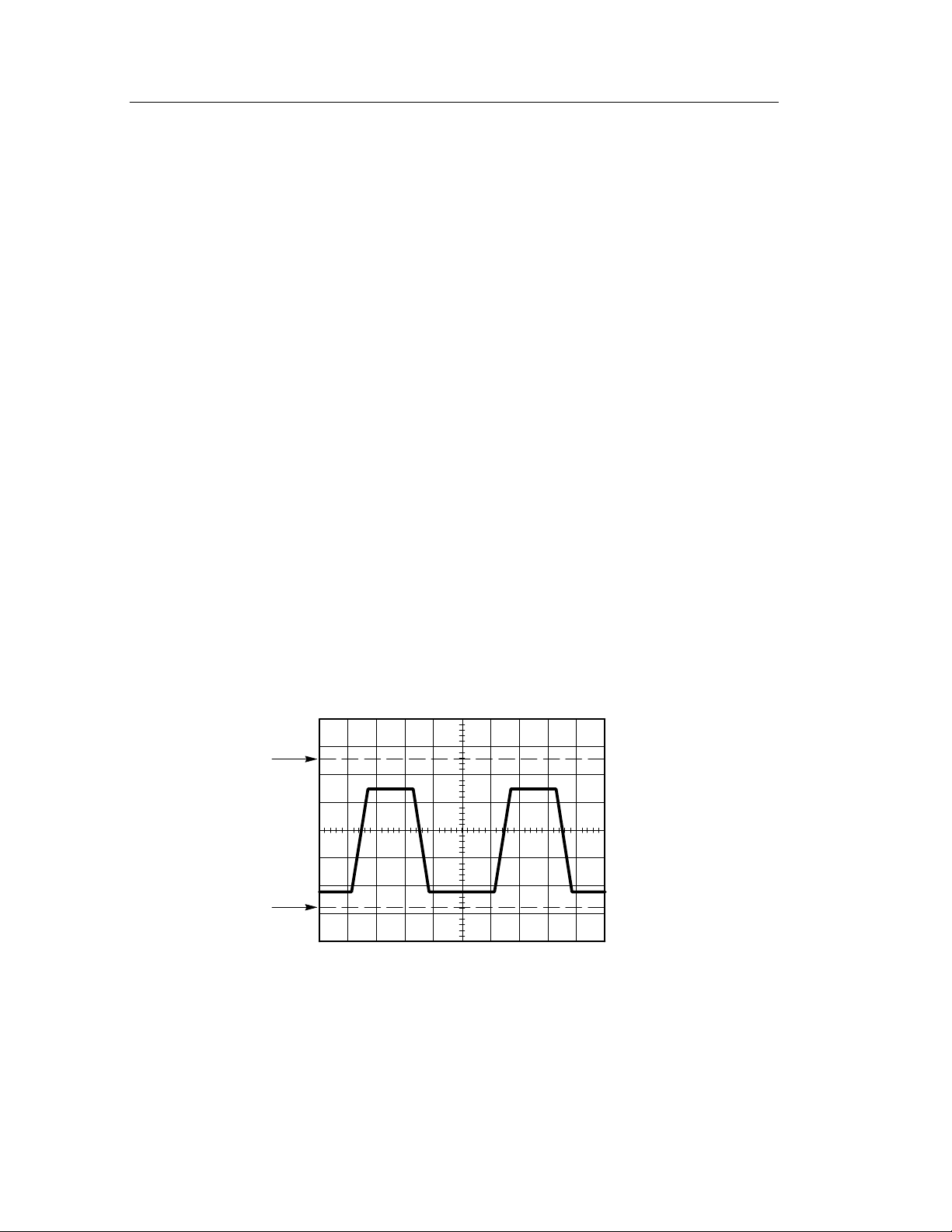
Overcompensated
Undercompensated
AUTOSET
button
1. Set the Probe option attenuation in the
channel menu to 10X. Set the switch to
10X on the P2200 probe and connect the
probe to channel 1 on the oscilloscope. If
you use t he probe hook-tip, ensure a
proper connection by firmly inserting the
tip onto the probe.
2. Attach the probe tip to the PROBE COMP
~5V connector and the referenc e lead to
the PROBE COMP Ground connector.
Display the channel and then push the
AUTOSET button.
3. Check the shape of the displayed
waveform.
Compensated correctly
8
4. If necessary, adjust your probe.
Repeat as necessary.
TDS1000/2000-Series Digital Oscilloscope User Manual
Page 27

Probe Attenuation Setting
Probes are available with various attenuation factors which affect the
vertical scale of the signal. The Probe Check function verifies that
the Probe attenuation option matches the attenuation of the probe.
As an al ternative method to Probe Check, you can push a vertical
menu button (such as the CH 1 MENU button), and select the Probe
option that matches the attenuation factor of your probe.
NOTE. The default setting for the Probe option is 10X.
Be sure that the Attenuation switch on the P2200 probe matches the
Probe option in the oscilloscope. Switch settings are 1X and 10X.
Getting Started
Attenuation switch
NOTE. When the Attenuation switch is set to 1X, the P2200 probe
limits the bandwidth of the oscilloscope to 7 MHz. To use the full
bandwidth of the oscilloscope, be sure to set the switch to 10X.
TDS1000/2000-Series Digital Oscilloscope User Manual
9
Page 28

Getting Started
Self Calibration
The self calibration routine lets you optimize the oscilloscope signal
path for maximum measurement accuracy. You can run the routine at
any time but should always run the routine if the ambient tempe rature changes by 5_ Cormore.
To compensate the signal path, disconne ct a ny probes or cable s from
the front-panel input connectors. Then, push the UTILITY button,
select the Do Self Cal option and follow the directions on the screen.
10
TDS1000/2000-Series Digital Oscilloscope User Manual
Page 29
Understanding Oscilloscope Functions
This chapter contains information on what you need to understand
before you use an oscilloscope. To use your oscilloscope effectively,
you need to learn about the following oscilloscope functions:
H Setting up the oscilloscope
H Triggering
H Acquiring signals (waveforms)
H Scaling and positioning waveforms
H Measuring waveforms
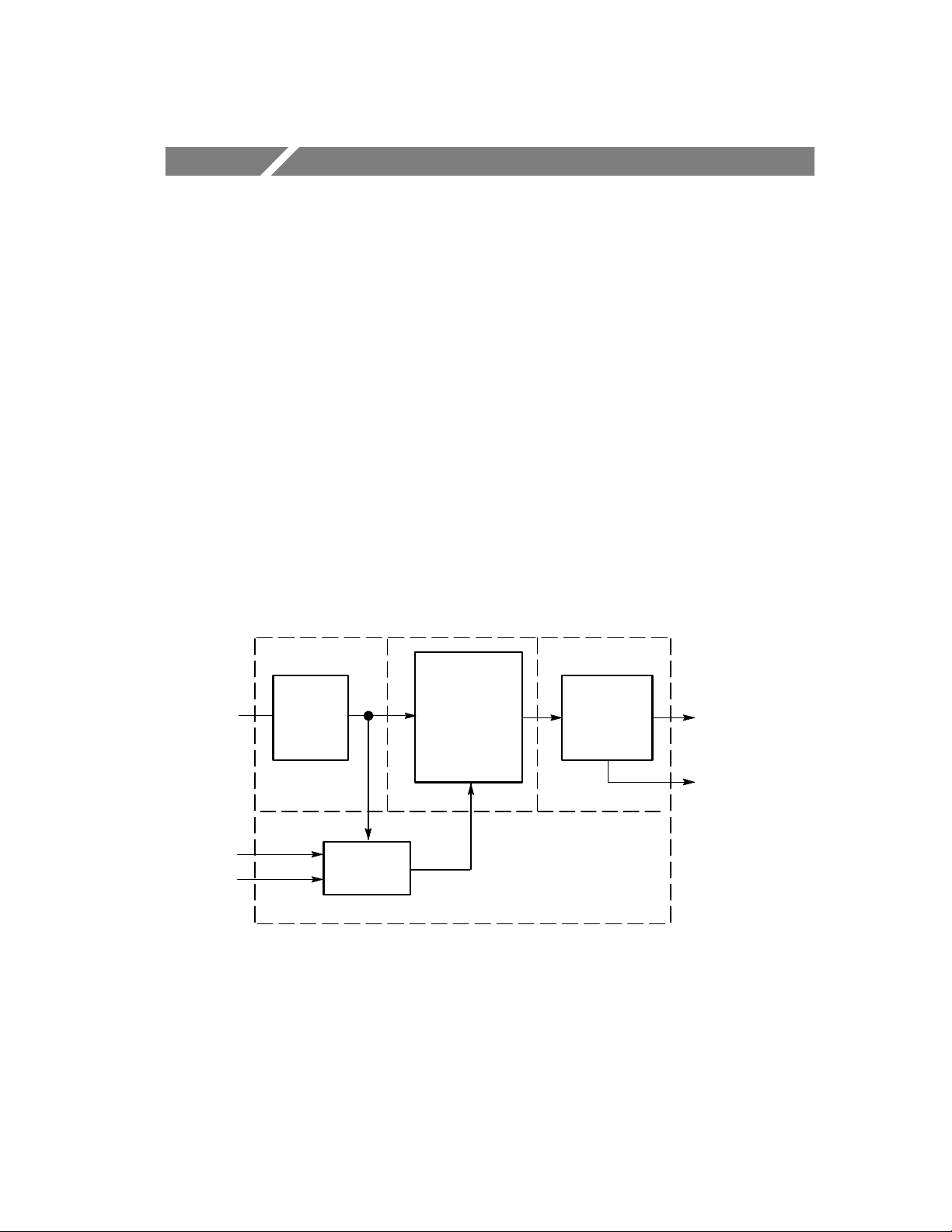
The figure below shows a block diagram of the various functions of
the oscilloscope and their relationship to each other.
Each
channel
Ext
AC Line
Vertical:
gain and
position
Trigger
Acquire data:
mode and
time base
Waveform
record:
2500 points
Display
Computer
interface
(TDS2CMA)
TDS1000/2000-Series Digital Oscilloscope User Manual
11
Page 30

Understanding Oscilloscope Functions
Setting Up the Oscilloscope
You should become familiar with three functions that you may use
often when operating your oscilloscope: Autoset, saving a setup, and
recalling a setup.
Using Autoset
The Autoset function obtains a stable waveform display for you. It
automatically adjusts the vertical scale, horizontal scale and trigger
settings. Autoset also displays several automatic measurements in the
graticule area, depending on the signal type.
Saving a Setup
The oscilloscope saves the current setup if you wait five seconds
after the last change before you power off the oscilloscope. The
oscilloscope recalls this setup the next time you apply power.
You can use the SAVE/RECALL Menu to permanently save up to ten
different setups.
Recalling a Setup
The oscilloscope can recall the last setup before power off, any of
your saved setups or the default setup. See page 175.
12
TDS1000/2000-Series Digital Oscilloscope User Manual
Page 31

Default Setup
The oscilloscope is set up for normal operation when it is shipped
from the factory. This is the default setup. To recall this setup, push
the DEFAULT SETUP button. To view the default settings, refer to
Appendix D: Default Setup.
Triggering
The trigger determines when the oscilloscope starts to acquire data
and display a waveform. When a trigger is set up properly, the
oscilloscope converts unstable displays or blank screens into
meaningful waveforms.
Understanding Oscilloscope Functions
Triggered waveform Untriggered waveforms
For oscilloscope-specific descriptions, refer to page 36 in the
Operating Basics chapter and page 99 in the Reference chapter.
TDS1000/2000-Series Digital Oscilloscope User Manual
13
Page 32

Understanding Oscilloscope Functions
When you push the RUN/STOP or SINGLE SEQ buttons to start an
acquisition, the oscilloscope goes through the following steps:
1. Acquires enough data to fill the portion of the waveform record
to the left of the trigger point. This is also called the pretrigger.
2. Continues to acquire data while waiting for the trigger condition
to occur.
3. Detects the trigger condition.
4. Continues to acquire data until the waveform record is full.
5. Displays the newly-acquired waveform.
NOTE. For Edge and Pulse triggers, the oscilloscope counts the rate
at which trigger events occur to determine trigger frequency and
displays the frequency in the lower right corner of the screen.
Source
You can use the Trigger Source options to select the signal that the
oscilloscope uses as a trigger. The source can be any signal
connected to a channel BNC, to the EXT TRIG BNC or the AC
power line (available only with Edge triggers).
14
TDS1000/2000-Series Digital Oscilloscope User Manual
Page 33

Understanding Oscilloscope Functions
Types
The oscilloscope provides three types of triggers: Edge, Video, and
Pulse Width.
Modes
You can select a Trigger Mode to define how the oscilloscope
acquires data when it does not detect a trigger condition. The modes
are Auto and Normal.
To perform a single sequence acquisition, push the SINGLE SEQ
button.
Coupling
You can use the Trigger Coupling option to determine which part of
the signal will pass to the trigger circuit. This can help you attain a
stable display of the waveform.
To use trigger coupling, push the TRIG MENU button, select an
Edge or Pulse trigger, and select a Coupling option.
NOTE. Trigger coupling affect s only the signal passed to the trigger
system. It does not affect the bandwidth or coupling of the signal
displayed on the screen.
To view the conditioned signal being passed to the trigger circuit,
push and hol d down the TRIG VIEW button.
TDS1000/2000-Series Digital Oscilloscope User Manual
15
Page 34

Understanding Oscilloscope Functions
Position
The horizontal position control establishes the time between the
trigger and the screen center. Refer to Horizontal Scale and Position;
Pretrigger Information on page 19 for more information on how to
use this control to position the trigger.
Slope and Level
The Slope and Level control s help to define the trigger. The Slope
option (Edge trigger type only) determines whether the oscilloscope
finds the trigger point on the rising or the falling edge of a signal.
The TRIGGER LEVEL knob controls where on the edge the trigger
point occurs.
Trigger level can be
adjusted vertically
Rising edge
Trigger slope can be rising or falling
Falling edge
16
TDS1000/2000-Series Digital Oscilloscope User Manual
Page 35

Acquiring Signals
When you acquire a signal, the oscilloscope converts it into a digital
form and displays a waveform. The acquisition mode defines how
the signal is digitized and the time base setting affects the time span
and level of detail in the acquisition.
Acquisition Modes
There are three acquisition modes: Sample, Peak Detect, and
Average.
Sample. In this acquisition mode, the oscilloscope samples the signal
in evenly spaced intervals to construct the waveform. This m ode
accurately represents signals most of the time.
However, this mode does not acquire rapid variations in the signal
that may occur between samples. This can result in aliasing
(described on page 20) and may cause narrow pulses to be missed. In
these cases, you should use the Peak Detect mode to acquire data.
Understanding Oscilloscope Functions
Peak Detect. In this acquisition mode, the oscilloscope finds the
highest and lowest values of the input signal over each sample
interval and uses these values to display the waveform. In thi s way,
the oscilloscope can acquire and display narrow pulses, which may
have otherwise been missed in Sample mode. Noise will appear to be
higher in this mode.
Average. In this acquisition mode, the oscilloscope acquires several
waveforms, averages them, and displays the resulting waveform. You
can use this mode to reduce random noise.
TDS1000/2000-Series Digital Oscilloscope User Manual
17
Page 36

Understanding Oscilloscope Functions
Time Base
The oscilloscope digitizes waveforms by acquiring the value of an
input signal at discrete points. The time base allows you to control
how often the values are digitized.
To adjust the time base to a horizontal scale that suits your purpose,
use the SEC/DIV knob.
Scaling and Positioning Waveforms
You can change the display of waveforms by adjusting their scale
and position. When you change the scale, the waveform display will
increase or decrease in size. When you change the position, the
waveform will move up, down, right, or left.
The channel reference indicator (located on the left of the graticule)
identifies each waveform on the display. The indicator points to the
ground level of the waveform record.
To view the display area and readouts, refer to page 28.
Vertical Scale and Position
You can change the vertical position of waveforms by moving them
up or down in the display. To compare data, you can align a
waveform above another or you can align waveforms on top of each
other.
You can change the vertical scale of a waveform. The waveform
display will contract or expand about the ground leve l.
For oscilloscope-specific descriptions, refer to page 34 in the
Operating Basics chapter and page 112 in the Reference chapter.
18
TDS1000/2000-Series Digital Oscilloscope User Manual
Page 37

Understanding Oscilloscope Functions
Horizontal Scale and Position; Pretrigger Information
You can adjust the HORIZONTAL POSITION control to view
waveform data before the trigger, after the trigger, or some of each.
When you change the horizontal position of a waveform, you are
actually changing the time between the trigger and the center of the
display. (This appears to move the waveform to the right or left on
the display.)
For example, if you want to find the cause of a glitch in your test
circuit, you might trigger on the glitch and make the pretrigger
period large enough to capture data before the glitch. You can then
analyze the pretrigger data and perhaps find the cause of the glitch.
You change the horizontal scale of all the waveforms by turni ng the
SEC/DIV knob. For example, you might want to see j ust one cycle of
a waveform to measure the overshoot on its rising edge.
The oscilloscope shows the horizontal scale as time per division in
the scale readout. Since all active waveforms use the same time base,
the oscilloscope only displays one value for all the active channels,
except when you use Window Zone. For information on how to use
the window function, refer to page 92.
For oscilloscope-specific descriptions, refer to page 35 in the
Operating Basics chapter and page 90 in the Reference chapter.
TDS1000/2000-Series Digital Oscilloscope User Manual
19
Page 38

Understanding Oscilloscope Functions
Time Domain Aliasing. Aliasing occurs when the oscilloscope does not
sample the signal fast enough to construct an accurate wave form
record. When this happens, the oscilloscope displays a waveform
with a frequency lower than the actual input waveform, or triggers
and displays an unstable waveform.
Actual high-frequency
waveform
Apparent low-frequency
waveform due to aliasing
Sampled points
The oscilloscope accurately represents signals, but is limited by the
probe bandwidth, the oscilloscope bandwidth, and the sample rate.
To avoid aliasing, the oscilloscope must sample the signal more than
twice as fast as the highest frequency component of the signal.
The highest frequency that the oscilloscope sampling rate can
theoretically represent is the Nyquist frequency. The sample rate i s
called the Nyquist rate, and is twice the Nyquist frequency.
20
TDS1000/2000-Series Digital Oscilloscope User Manual
Page 39

Understanding Oscilloscope Functions
Oscilloscope models with 60 MHz or 100 MHz bandwidth sample at
rates up to 1 GS/s. Models with 200 MHz bandwidth sample at rates
up to 2 GS/s. In both cases, these maximum sample rates are at least
ten times the bandwidth. These high sample rates help reduce the
possibility of aliasing.
There are several ways to check for aliasing:
H Turn the SEC/DIV knob to change the horizontal scale. If the
shape of the waveform changes drastically, you may have
aliasing.
H Select the Peak Detect acquisition mode (described on page 17).
This mode samples the highest and lowest values so that the
oscilloscope can detect faster signals. If the shape of the
waveform changes drastically, you may have aliasing.
H If the trigger frequency is faster than the display information, you
may have aliasing or a waveform that crosses the trigger level
multiple times. Examining the waveform should allow identifying whether the shape of the signal is going to allow a single
trigger crossing per cycle at the selected trigger level. If multiple
triggers are likely to occur, select a trigger level that will generate
only a single trigger per cycle. If the trigger frequency is still
faster than the display indicates, you may have aliasing.
If the trigger frequency is slower, this test is not useful.
H If the signal you are viewing is also the trigger source, use the
graticule or the cursors to estimate the frequency of the displayed
waveform. Compare this to the Trigger Frequency readout in the
lower right corner of the screen. If they differ by a large amount,
you may have aliasing.
TDS1000/2000-Series Digital Oscilloscope User Manual
21
Page 40

Understanding Oscilloscope Functions
The next table lists the time bases that you should use to avoid
aliasing at various frequencies and the respective sample rate. At the
fastest SEC/DIV setting, aliasing is not likely to occur due to the
bandwidth limitations of the oscilloscope input ampl ifiers.
Settings to avoid aliasing in Sample mode
Time base
(SEC/DIV)
Samples per
second
Maximum
frequency
component
25 to 250.0 ns 1GS/sor
2GS/s*
500.0 ns 500.0 MS/s 200.0 MHz**
1.0 s
2.5 s
5.0 s
10.0 s
25.0 s
50.0 s
100.0 s
250.0 s
500.0 s
* Depending on the oscilloscope model.
** Bandwidth reduced to 6 MHz with a 1X probe.
250.0 MS/s 125.0 MHz**
100.0 MS/s 50.0 MHz**
50.0 MS/s 25.0 MHz**
25.0 MS/s 12.5 MHz**
10.0 MS/s 5.0 MHz
5.0 MS/s 2.5 MHz
2.5 MS/s 1.25 MHz
1.0 MS/s 500.0 kHz
500.0 kS/s 250.0 kHz
200.0 MHz**
22
TDS1000/2000-Series Digital Oscilloscope User Manual
Page 41

Understanding Oscilloscope Functions
Settings to avoid aliasing in Sample mode (Cont.)
Maximum
Time base
(SEC/DIV)
1.0 ms 250.0 kS/s 125.0 kHz
2.5 ms 100.0 kS/s 50.0 kHz
5.0 ms 50.0 kS/s 25.0 kHz
10.0 ms 25.0 kS/s 12.5 kHz
25.0 ms 10.0 kS/s 5.0 kHz
50.0 ms 5.0 kS/s 2.5 kHz
100.0 ms 2.5 kS/s 1.25 kHz
Samples per
second
frequency
component
250.0 ms 1.0 kS/s 500.0 Hz
500.0 ms 500.0 S/s 250.0 Hz
1.0 s 250.0 S/s 125.0 Hz
2.5 s 100.0 S/s 50.0 Hz
5.0 s 50.0 S/s 25.0 Hz
10.0 s 25.0 S/s 12.5 Hz
25.0 s 10.0 S/s 5.0 Hz
50.0 s 5.0 S/s 2.5 Hz
TDS1000/2000-Series Digital Oscilloscope User Manual
23
Page 42
Understanding Oscilloscope Functions
T aking Measurements
The oscilloscope displays graphs of voltage versus time and can help
you to measure the displayed waveform.
There are several ways to take measurements. You can use the
graticule, the cursors, or an automated measurement.
Graticule
This method allows you to make a quick, visual estimate. For
example, you might look at a waveform amplitude and determine
that it is a little more than 100 mV.
You can take simple measurements by counting the major and minor
graticule divisions involved and multiplying by the scale factor.
For example, if you counted five major vertical graticule divisions
between the minimum and maximum values of a waveform and
knew you had a scale factor of 100 mV/division, then you could
easily calculate your peak-to-peak voltage as follows:
5 divisions x 100 mV/division = 500 mV.
Cursor
Cursor
24
TDS1000/2000-Series Digital Oscilloscope User Manual
Page 43

Understanding Oscilloscope Functions
Cursors
This method allows you to take measurements by moving the
cursors, which always appear in pairs, and reading their numeric
values from the display readouts. There are two types of cursors:
Voltage and Time.
When you use cursors, be sure to set the Source to the waveform on
the display that you want to measure.
To use cursors, push the CURSOR button.
Voltage Cursors. Voltage cursors appear as horizontal lines on the
display and measure the vertical parameters.
Time Cursors. Time cursors appear as vertical lines on the display and
measure the horizontal parameters.
Automatic
The MEASURE Menu can take up to five automatic measurements.
When you take automatic measurements, the oscilloscope does all
the calculating for you. Because the measurements use the waveform
record points, they are more accurate than the graticule or cursor
measurements.
Automatic measurements use readouts to show measurement results.
These readouts are updated periodically as the oscilloscope acquires
new data.
For measurement descriptions, refer to page 94 in the Reference
chapter.
TDS1000/2000-Series Digital Oscilloscope User Manual
25
Page 44

Understanding Oscilloscope Functions
26
TDS1000/2000-Series Digital Oscilloscope User Manual
Page 45
Operating Basics
The front panel is divided into easy-to-use functional areas. This
chapter provides you with a quick overview of the control s and the
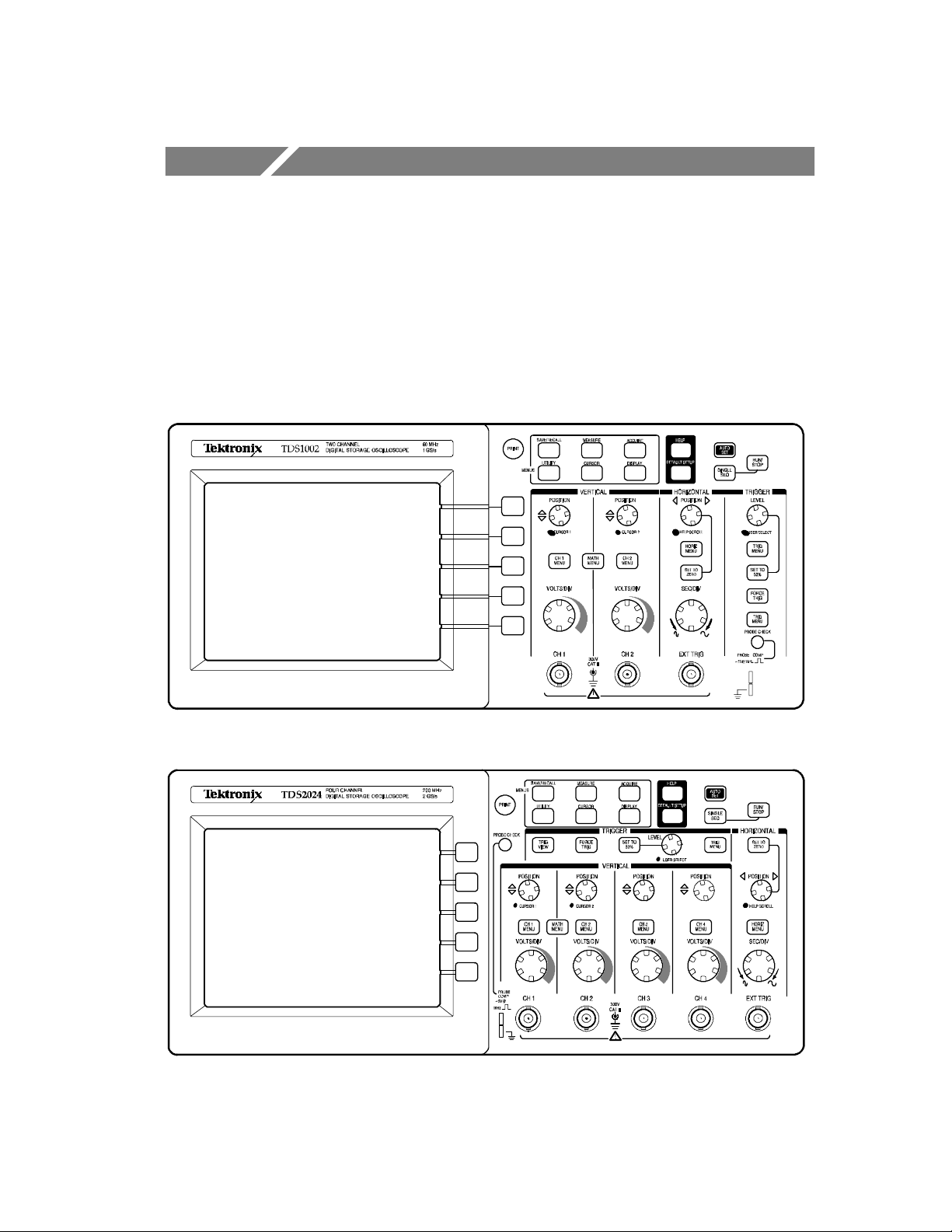
information displayed on the screen. The next figure shows the front
panels for 2-channel and 4-channel models.
2-channel models
4-channel models
TDS1000/2000-Series Digital Oscilloscope User Manual
27
Page 46
Operating Basics
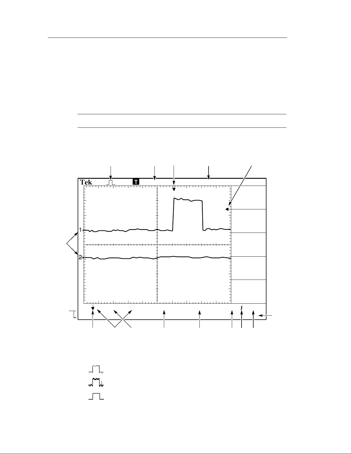
Display Area
In addition to displaying waveforms, the display is filled with many
details about the waveform and the oscilloscope control settings.
NOTE. For similar details for the FFT function, refer to page 119.
6
15
12 43
CH1 500mVB
Default setup recalled
W
Trig’d
M Pos:-11.30ms
5
750mVCH1W 100msM 500msCH2 200mV
1.00000kHz
16
28
7
8
9
10
1. Icon display shows acquisition mode.
Sample mode
Peak detect mode
Average mode
TDS1000/2000-Series Digital Oscilloscope User Manual
14
131211
Page 47
2. Trigger status indicates the following:
g’d
Acq.Complete.
Operating Basics
Armed.
triggers are ignored in this state.
R
Ready.
oscilloscope is ready to accept a trigger.
T
Tri
posttrigger data.
Stop.
Sequence acquisition.
R
Auto.
waveforms in the absence of triggers.
Scan.
data continuously in scan mode.
3. Marker shows horizontal trigger position. Turn the HORIZON-
TAL POSITION knob to adjust the position of the marker.
The oscilloscope is acquiring pretrigger data. All
All pretrigger data has been acquire d and the
.
The oscilloscope has seen a trigger and is acquiring the
The oscilloscope has stopped acquiring waveform data.
The oscilloscope has completed a Single
The oscilloscope is in auto mode and is acquiring
The oscilloscope is acquiring and displaying waveform
4. Readout shows the time at the center graticule. The trigger time
is zero.
5. Marker shows Edge or Pulse Width trigger level.
6. On-screen markers show the ground reference points of the
displayed waveforms. If there is no marker, the channel is not
displayed.
TDS1000/2000-Series Digital Oscilloscope User Manual
29
Page 48

Operating Basics
7. An arrow icon indicates that the waveform is inverted.
8. Readouts show t he vertical scale factors of the channe ls.
9. AB
icon indicates that the channel is bandwidth limited.
W
10. Readout shows main time base setting.
11. Readout shows window time base setting if it is in use.
12. Readout shows trigger source used for triggering.
13. Icon shows selected trigger type as follows:
-- Edge trigger for the rising edge.
-- Edge trigger for the falling edge.
-- Video trigger for line sync.
-- Video trigger for field sync.
-- Pulse Width trigger, positive polarity.
-- Pulse Width trigger, negative polarity.
14. Readout shows Edge or Pulse Width trigger level.
15. Display area shows helpful messages; some messages display for
only three seconds.
30
If you recall a saved waveform, readout shows information about
the reference waveform, such as RefA 1.00V 500µs.
16. Readout shows trigger frequency.
TDS1000/2000-Series Digital Oscilloscope User Manual
Page 49

Operating Basics
Message Area
The oscilloscope displays a message area (item number 15 in the
previous figure) at the bottom of the screen that conveys t he
following types of helpful information:
H Directions to access another menu, such as when you push the
TRIG MENU button:
For TRIGGER HOLDOFF, go to HORIZONTAL Menu
H Suggestion of what you might want to do next, such as when you
push the MEASURE button:
Push an option button to change its measurement
H Information about the action the oscilloscope performed, such as
when you push the DEFAULT SETUP button:
Default setup recalled
H Information about the waveform, such as when you push the
AUTOSET button:
Square wave or pulse detected on CH1
TDS1000/2000-Series Digital Oscilloscope User Manual
31
Page 50

Operating Basics
Using the Menu System
The user interface of TDS1000- and TDS2000-series oscilloscopes
was designed for easy access to specialized functions through the
menu structure.
When you push a front-panel button, the oscilloscope displays the
corresponding menu on the right side of the screen. The menu shows
the options that are available when you push the unlabeled option
buttons directly to the right of the screen. (Some documentation may
also refer to the option buttons as screen buttons, side-menu buttons,
bezel buttons, or soft keys.)
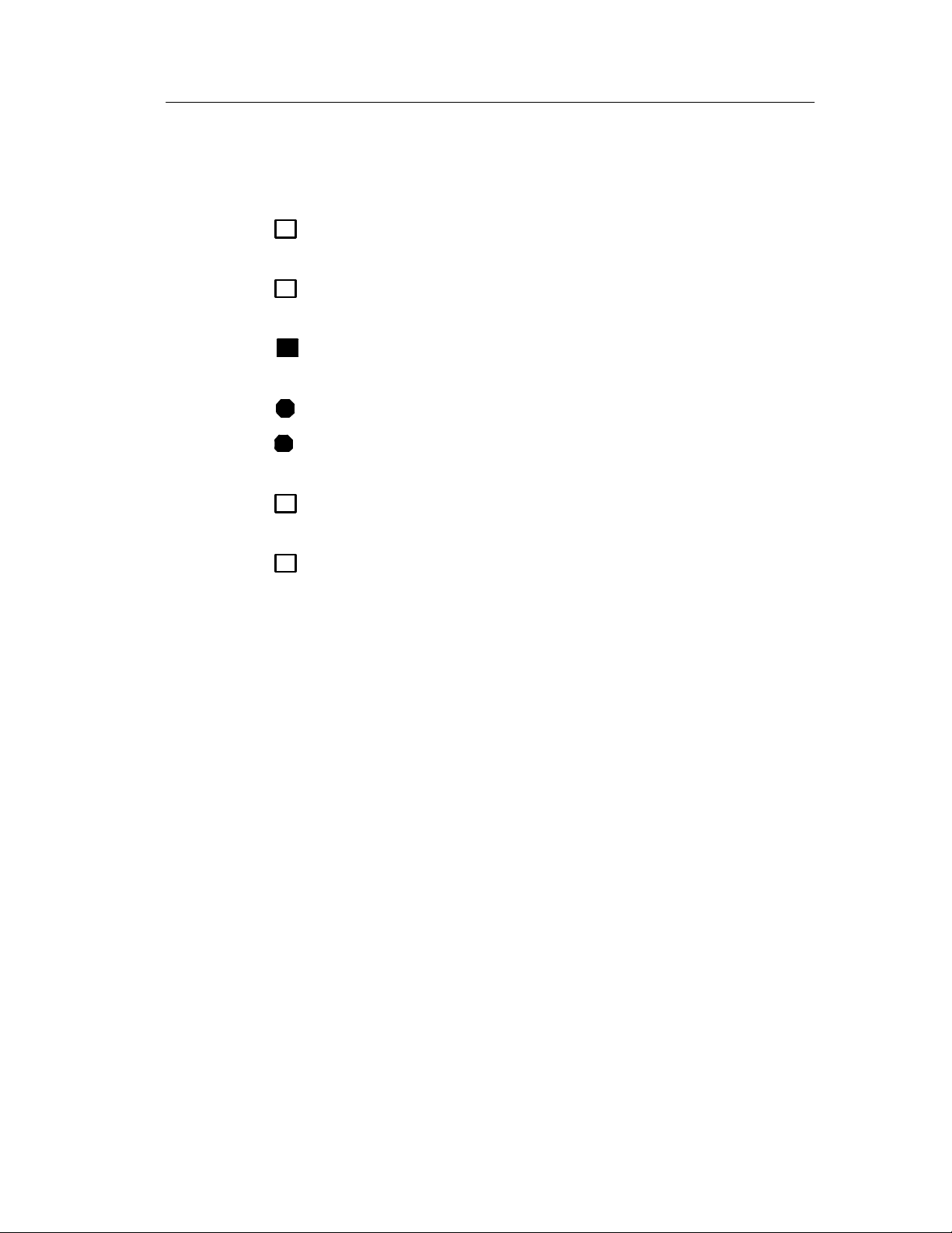
The oscilloscope uses four methods to display menu options:
H Page (Submenu) Selection: For some menus, you can use the top
option button to choose two or thre e submenus. Each time you
push the top button, the options change. For example, when you
push the top button in the SAVE/REC Menu, the oscilloscope
cycles through the Setups and Waveforms submenus.
H Circular List: The oscilloscope sets the parameter to a different
value each time you push the option button. For example, you
can push the CH 1 MENU button and then push the top option
button to cycle through the Vertical (channel) Coupling options.
32
TDS1000/2000-Series Digital Oscilloscope User Manual
Page 51

Operating Basics
H Action: The oscilloscope displays the type of action that will
immediately occur when you push an Action option button. For
example, when you push the DISPLAY Menu button and then
push the Contrast Increase option button, the oscilloscope
changes the contrast immediately.
H Radio: The oscilloscope uses a different button for each option.
The currently-selected option is highlighted. For example, the
oscilloscope displays various acquisition mode options when you
push the ACQUIRE Menu button. To select an option, push the
corresponding button.
Page Selection Action RadioCircular List
or
or
or
TDS1000/2000-Series Digital Oscilloscope User Manual
33
Page 52

Operating Basics
Vertical Controls
All models
CH 1, CH 2, CH 3, CH 4, CURSOR 1 and CURSOR 2 POSITION. Positions
the waveform vertically. Whe n you display and use cursors, an LED
lights to indicate the alterna tive function of the knobs to move the
cursors.
CH 1, CH 2, CH 3 & CH 4 MENU. Displays the vertical menu selections
and toggles the display of the channel waveform on and off.
VOLTS/DIV (CH 1, CH 2, CH 3 & CH 4). Selects calibrated scale factors.
MATH MENU. Displays waveform math operations menu and can also
be used to toggle the math waveform on and off.
34
TDS1000/2000-Series Digital Oscilloscope User Manual
Page 53

Horizontal Controls
Operating Basics
2-channel models
POSITION. Adjusts the horizontal position of all channel and math
waveforms. The resolution of this control varies with the time base
setting. For information on windows, refer to page 92.
NOTE. To make a large adjustment to the horizontal position, turn the
SEC/DIV knob to a larger value, change the horizontal position, and
then turn the SEC/DIV knob back to the previous value.
When you view help topics, you can use this knob to scroll through
links or index entries.
4-channel models
TDS1000/2000-Series Digital Oscilloscope User Manual
35
Page 54

Operating Basics
HORIZ MENU. Displays the Horizontal Menu.
SET TO ZERO. Sets the horizontal position to zero.
SEC/DIV. Selects the horizontal time/div (scale factor) for the main or
the window time base. When Window Z one is enabled, it changes
the width of the window zone by changing the window time base.
Refer to page 92 for details about creating and using Window Zone.
Trigger Controls
4-channel models
2-channel models
LEVEL and USER SELECT. When you use an Edge trigger, the primary
function of the LEVEL knob is to set the amplitude level the signal
must cross to cause an acquisition. You can also use the knob to
perform USER SELECT alternative functions. The LED lights below
the knob to indicate an alternative function.
36
TDS1000/2000-Series Digital Oscilloscope User Manual
Page 55

Operating Basics
USER SELECT Description
Holdoff Sets the amount of time before another trigger event can
be accepted; refer to Holdoff on page 109
Video line number Sets the oscilloscope to a specific line number when the
Trigger Type option is set to Video and the Sync option is
set to Line Number
Pulse width Sets the width of the pulse when the Trigger Type option is
set to Pulse and you select the Set Pulse Wdith option
TRIG MENU. Displays the Trigger Menu.
SET TO 50%. The trigger level is set to the vertical midpoint between
the peaks of the trigger signal.
FORCE TRIG. Completes an acquisition regardless of an adequate
trigger signal. This button has no effect if the acquisition is already
stopped.
TRIG VIEW. Displays the trigger waveform in place of the channel
waveform while the TRIG VIEW button is held down. You can use
this to see how the trigger settings affect the trigger signal, such as
trigger coupling.
TDS1000/2000-Series Digital Oscilloscope User Manual
37
Page 56

Operating Basics
Menu and Control Buttons
All models
SAVE/RECALL. Displays the Save/Recall Menu for setups and
waveforms.
MEASURE. Displays the automated measurements menu.
ACQUIRE. Displays the Acquire Menu.
DISPLAY. Displays the Display Menu.
CURSOR. Displays the Cursor Menu. Vertical Position controls adjust
cursor position while displaying the Cursor Menu and the cursors are
activated. Cursors remain displayed (unless the Type option is set to
Off) after l eaving the Cursor Menu but are not adjusta ble.
UTILITY. Displays the Utility Menu.
HELP. Displays the Help Menu.
DEFAULT SETUP. Recalls the factory setup.
AUTOSET. Automatically sets the oscilloscope controls to produce a
usable display of the input signals.
SINGLE SEQ. Acquires a single waveform and then stops.
RUN/STOP. Continuously acquires waveforms or stops the acquisition.
PRINT. Starts print operations. An extension module with a Ce ntron-
ics, RS-232, or GPIB port is required. Refer to Optional Accessories
on page 169.
38
TDS1000/2000-Series Digital Oscilloscope User Manual
Page 57
Connectors
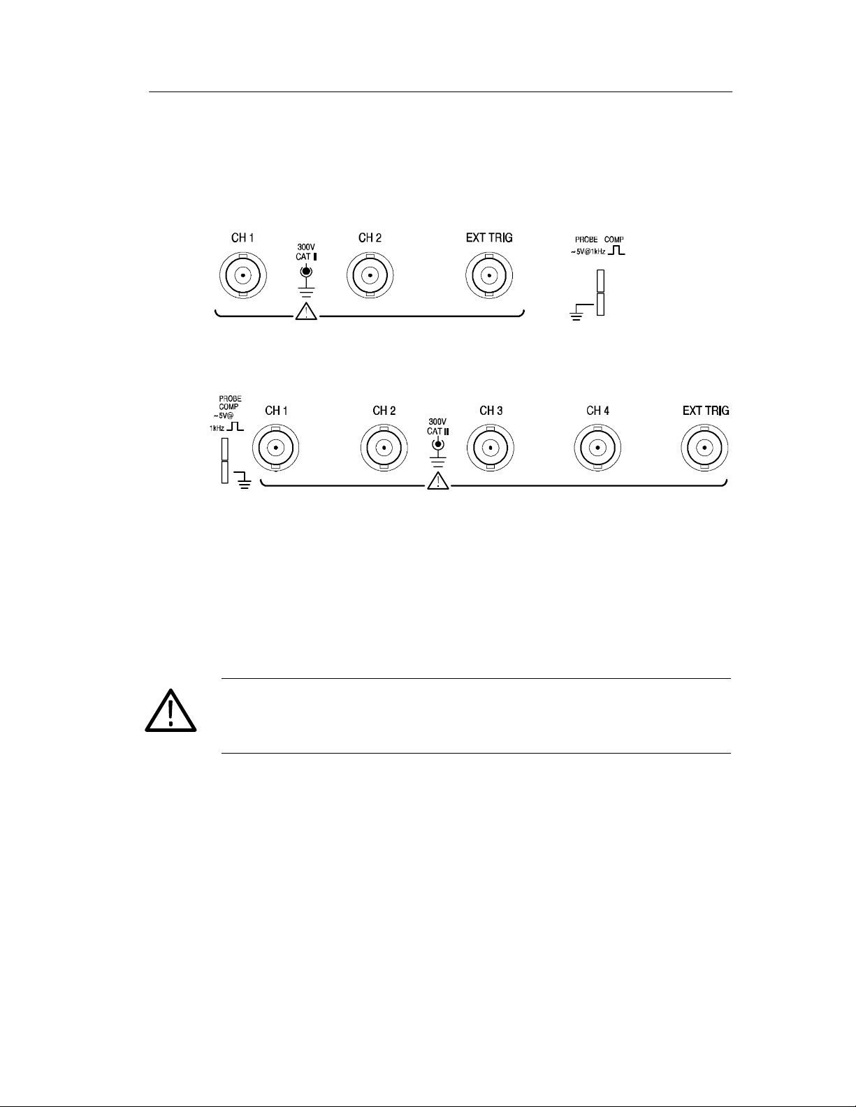
2-channel models
Operating Basics
4-channel models
PROBE COMP. Voltage probe compensation output and ground. Use to
electrically match the probe to the oscilloscope input circuit. Refer to
page 8. The probe compensation ground and BNC shields connect to
earth ground and are considered to be ground terminals
CAUTION. If you connect a voltage source to a ground terminal, you
may damage the oscilloscope or the circuit under test. To avoid this,
do not connect a voltage source to any ground terminals.
CH 1, CH 2, CH 3 & CH 4. Input connectors for waveform display.
EXT TRIG. Input connector for an external trigger source. Use the
Trigger Menu to select the Ext or Ext/5 trigger source.
TDS1000/2000-Series Digital Oscilloscope User Manual
39
Page 58

Operating Basics
40
TDS1000/2000-Series Digital Oscilloscope User Manual
Page 59

Application Examples
This section presents a series of application examples. These
simplified examples highlight the features of the oscilloscope and
give you ideas for using it to solve your own test problems.
H Taking simple measurements
Using Autoset
Using the Measure Menu to take automatic measurements
Measuring two signals and calculating gain
H Taking cursor measurements
Measuring ring frequency and ring amplitude
Measuring pulse width
Measuring rise time
H Analyzing signal detail
Looking at a noisy signal
Using the average function to separate a signal from noise
H Capturing a single-shot signal
Optimizing the acquisition
H Measuring propagation delay
H Triggering on a pulse width
H Triggering on a video signal
Triggering on video fields and video lines
Using the window function to see waveform details
H Analyzing a differential communication signal using math
functions
H Viewing impedance changes in a network using XY mode and
persistance
TDS1000/2000-Series Digital Oscilloscope User Manual
41
Page 60
Application Examples
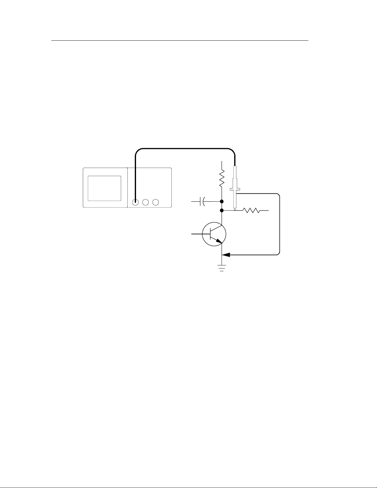
T aking Simple Measurements
You need to see a signal in a circuit, but you do not know the
amplitude or frequency of the signal. You want to quickly display the
signal and measure the frequency, period, and peak-to-pea k
amplitude.
CH 1
Using Autoset
To quickly display a signal, follow these steps:
1. Push the CH 1 MENU but ton and set the Probe option
attenuation to 10X.
2. Set the switch to 10X on the P2200 probe.
42
TDS1000/2000-Series Digital Oscilloscope User Manual
Page 61

Application Examples
3. Connect the channel 1 probe to the signal.
4. Push the AUTOSET button.
The oscilloscope sets the vertical, horizontal, and trigger controls
automatically. If you want to optimize the display of the waveform,
you can manually adjust these controls.
NOTE. The oscilloscope displays relevant automatic measurements in
the waveform area of the screen based on t he signal type detect ed.
For oscilloscope-specific descriptions, refer to page 79 in the
Reference chapter.
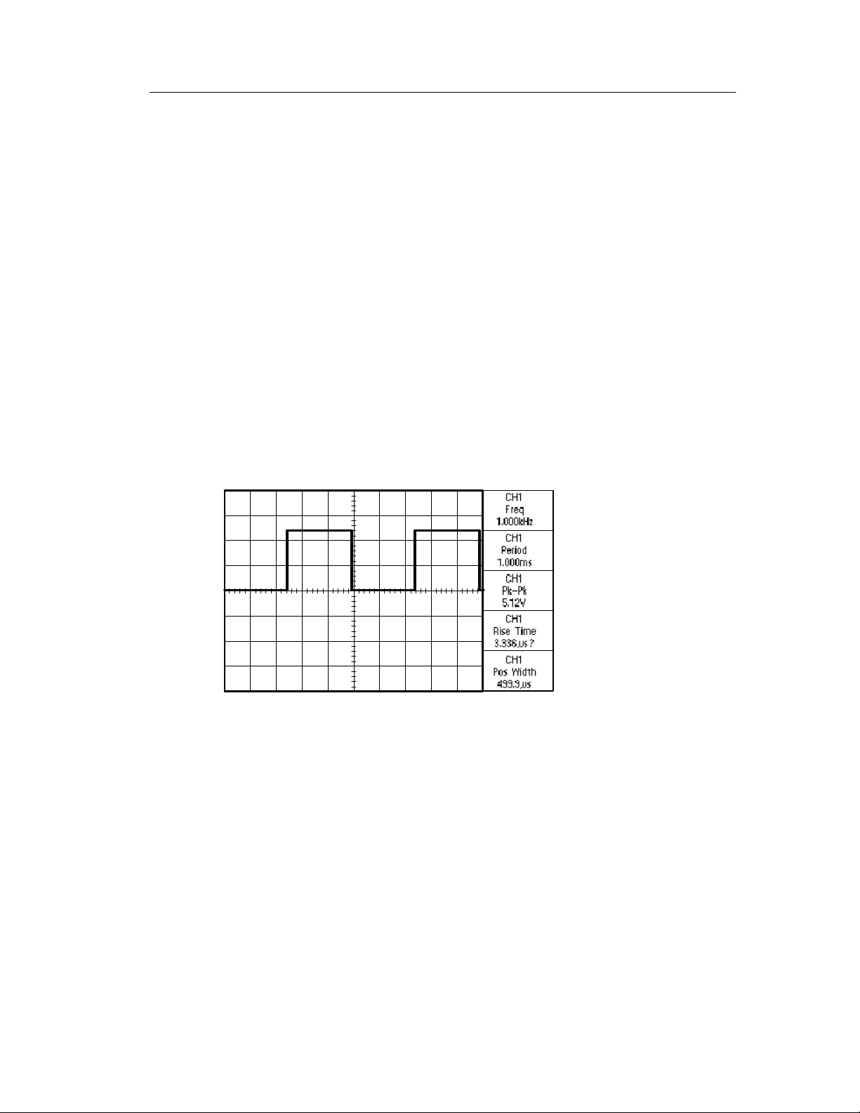
Taking Automatic Measurements
The oscilloscope can take automatic measurements of most
displayed signals. To measure signal frequency, period, and
peak-to-peak amplitude, rise time, and positive width, follow these
steps:
1. Push the MEASURE button to see the Measure Menu.
2. Push the t op option button; the Measure 1 Menu appears.
TDS1000/2000-Series Digital Oscilloscope User Manual
43
Page 62

Application Examples
3. Push the Type option button and select Freq.
The Va l ue readout displays the measurement and updates.
NOTE. If a question mark (?) displays in the Value readout, turn the
VOLTS/DIV knob for the appropriate channel to increase t he
sensitivity or change the SEC/DIV setting.
4. Push the Back option button.
5. Push the sec ond option button from the top; the Measure 2 Menu
appears.
6. Push the Type option button and select Period.
The Va l ue readout displays the measurement and updates.
7. Push the Back option button.
8. Push the m iddle option button; the Measure 3 Menu appears.
9. Push the Type option button and select Pk-Pk.
The Va l ue readout displays the measurement and updates.
10. Push the Back option button.
44
TDS1000/2000-Series Digital Oscilloscope User Manual
Page 63
Application Examples
11. Push the second option button from the bottom; the Measure 4
Menu appears.
12. Push the Type option button and select Rise Time.
The Va l ue readout displays the measurement and updates.
13. Push the Back option button.
14. Push the bottom option button; the Measure 5 Menu appears.
15. Push the Type option button and select Pos Width.
The Va l ue readout displays the measurement and updates.
16. Push the Back option button.
TDS1000/2000-Series Digital Oscilloscope User Manual
45
Page 64

Application Examples
Measuring Two Signals
You are testing a piece of equipme nt and need to measure the gain of
the audio amplifier. You have an audio generator that can inject a test
signal at the amplifier input. Connect two oscilloscope channels to
the amplifier input and output as shown. Measure both signal levels
and use the measurements to calculate the gain.
CH 1 CH 2
46
TDS1000/2000-Series Digital Oscilloscope User Manual
Page 65

Application Examples
To activate and display the signal s connected to channel 1 and to
channel 2, follow these steps:
1. If the channels are not displayed, push the CH 1 MENU and
CH 2 MENU buttons.
2. Push the AUTOSET button.
To select measurements for the two channels, follow these steps:
1. Push the Measure button to see the Measure Menu.
2. Push the t op option button; the Measure 1 Menu appears.
3. Push the Source option button and select CH1.
4. Push the Type option button and select Pk-Pk.
5. Push the Back option button.
6. Push the sec ond option button from the top; the Measure 2 Menu
appears.
7. Push the Source option button and select CH2.
8. Push the Type option button and select Pk-Pk.
9. Push the Back option button.
Read the displayed peak-to-peak amplitudes for both channels.
10. To calculate the amplifier voltage gain, use these equations:
VoltageGain =
VoltageGain (dB) = 20 x log10(VoltageGain)
output amplitude
input amplitude
TDS1000/2000-Series Digital Oscilloscope User Manual
47
Page 66

Application Examples
T aking Cursor Measurements
You can use the cursors to quickly take time and voltage measurements on a waveform.
Measuring Ring Frequency
To measure the ring frequency at the rising edge of a signal, follow
these steps:
1. Push the CURSOR button to see the Cursor Menu.
2. Push the Type option button and select Time.
3. Push the Source option button and select CH1.
4. Turn the CURSOR 1 knob to place a c ursor on the first peak of
the ring.
5. Turn the CURSOR 2 knob to place a cursor on the second peak
of the ring.
You can see the delta time and frequency (the measured ring
frequency) in the Cursor Menu.
48
TDS1000/2000-Series Digital Oscilloscope User Manual
Page 67

Application Examples
Measuring Ring Amplitude
You measured the ring frequency in the previous example. Now you
want to measure the amplitude of the ringing. To measure the
amplitude, follow these steps:
1. Push the CURSOR button to see the Cursor Menu.
2. Push the Type option button and select Voltage.
3. Push the Source option button and select CH1.
4. Turn the CURSOR 1 knob to place a c ursor on the highest peak
of the ring.
5. Turn the CURSOR 2 knob to place a c ursor on the lowest point
of the ring.
You can see the following measurements in the Cursor Menu:
H The delta voltage (peak-to-peak voltage of the ringing)
H The voltage at Cursor 1
H The voltage at Cursor 2
TDS1000/2000-Series Digital Oscilloscope User Manual
49
Page 68

Application Examples
Measuring Pulse Width
You are analyzing a pulse waveform, and you want to know the
width of the pulse. To measure the width of a pulse using the time
cursors, follow these steps:
1. Push the CURSOR button to see the Cursor Menu.
LEDs light under the VERTICAL POSITION knobs to indicate
the alternative CURSOR1 and CURSOR2 functions.
2. Push the Source option button and select CH1.
3. Push the Type option button and select Time.
4. Turn the CURSOR 1 knob to place a cursor on the rising edge of
the pulse.
5. Turn the CURSOR 2 knob to place the remaining cursor on the
falling edge of the pulse.
You can see the following measurements in the Cursor Menu:
H The time at Cursor 1, relative to the trigger.
H The time at Cursor 2, relative to the trigger.
H The delta time, which is the pulse width measurement.
50
TDS1000/2000-Series Digital Oscilloscope User Manual
Page 69

Application Examples
NOTE. The Positive Width measurement is available as an automatic
measurement in the Measure Menu, described on page 94.
The Positive Width measurement also displays when you select the
Single-Cycle Square option in the AUTOSET Menu. Refer to page 82.
Measuring Rise Time
After measuring the pulse width, you decide that you need to check
the rise time of the pulse. Typically, you measure rise time between
the 10% and 90% levels of the waveform. To measure the rise time,
follow these steps:
1. Turn the SEC/DIV knob to display the rising edge of the
waveform.
TDS1000/2000-Series Digital Oscilloscope User Manual
51
Page 70

Application Examples
2. Turn the VOLTS/DIV and VERTICAL POSITION knobs to set
the waveform amplitude to about five divisions.
3. Push the CH 1 MENU button to see the CH1 Menu if it is not
displayed.
4. Push the Vo l t s/ D i v option button and select Fine.
5. Turn the VOLTS/DIV knob to set the waveform amplitude to
exactly five divisions.
6. Turn the VERTICAL POSITION knob to center the waveform;
position the baseline of the waveform 2.5 divisions below the
center graticule.
7. Push the CURSOR button to see the Cursor Menu.
8. Push the Type option button and select Time.
9. Turn the CURSOR 1 knob to place the cursor at the point where
the waveform crosses the second graticule line below center
screen. This is the 10% level of the waveform.
52
TDS1000/2000-Series Digital Oscilloscope User Manual
Page 71

Application Examples
10. Turn the CURSOR 2 knob to place the second cursor at the point
where the waveform crosses the second graticule line above
center screen. This is the 90% level of the waveform.
11. The Delta readout in the Cursor Menu is t he rise time of the
waveform.
5 divisions
NOTE. The Rise Time measurement is available as an automatic
measurement in the Measure Menu, described on page 94.
The Rise Time measurement also displays when you select the Rising
Edge option in the AUTOSET Menu. R efer to page 82.
TDS1000/2000-Series Digital Oscilloscope User Manual
53
Page 72

Application Examples
Analyzing Signal Detail
You have a noisy signal displayed on the oscilloscope and you need
to know m ore about it. You suspect that the signal contains much
more detail than you can now see in the display.
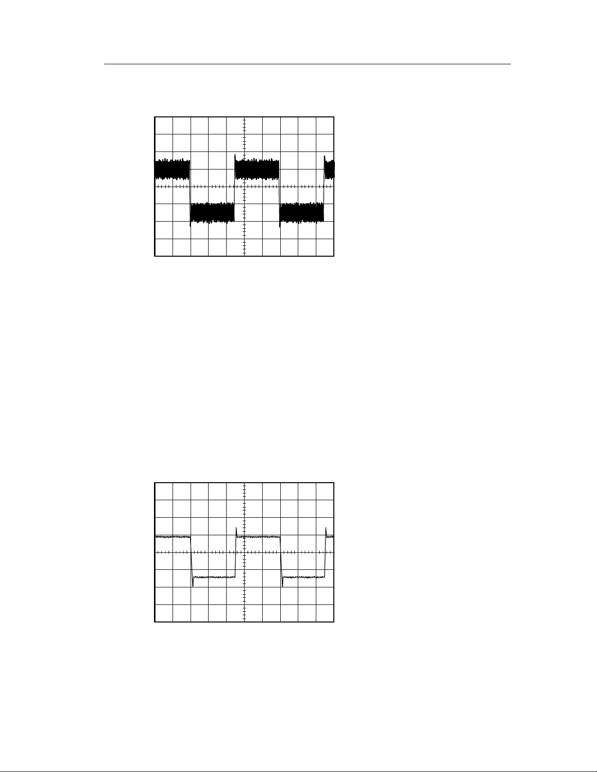
Looking at a Noisy Signal
The signal appears noisy and you suspect that noise is causing
problems in your circuit. To better analyze the noise, follow these
steps:
1. Push the ACQUIRE button to see the Acquire Menu.
2. Push the Peak Detect option button.
3. If necessary, push the DISPLAY button to see the Display Menu.
Use the Contrast Increase and Contrast Decrease option
buttons to adjust the contrast to see the noise more easily.
Peak detect emphasizes noise spikes and glitches in your signal,
especially when the time base is set to a slow setting.
54
TDS1000/2000-Series Digital Oscilloscope User Manual
Page 73
Application Examples
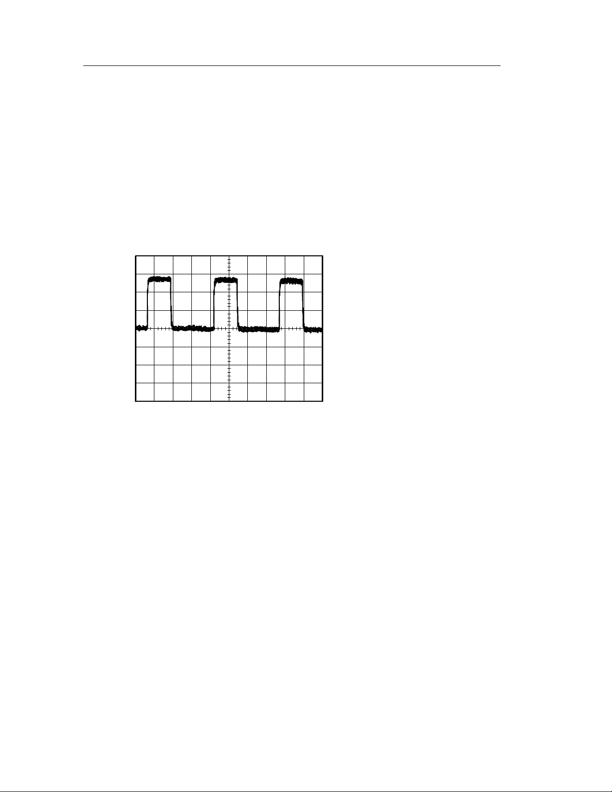
Separating the Signal from Noise
Now you want to analyze the signa l shape and i gnore the noise. To
reduce random noise in the oscilloscope display, follow these steps:
1. Push the ACQUIRE button to see the Acquire Menu.
2. Push the Average option button.
3. Push the Averages option button to see the effects of varying the
number of running averages on the waveform display.
Averaging reduces random noise and makes it easier to see detail in a
signal. In the example below, a ring shows on the rising and falling
edges of the signal when the noise is removed.
TDS1000/2000-Series Digital Oscilloscope User Manual
55
Page 74
Application Examples
Capturing a Single-Shot Signal
The reliability of a reed relay in a piece of equipment has been poor
and you need to investigate the problem. You suspect that t he relay
contacts arc when the relay opens. The fastest you can open and
close the relay is about once per minute so you need to capture the
voltage across the relay as a single-shot acquisition.
To set up for a single-shot acquisition, follow these steps:
1. Turn the vertical VOLTS/DIV and horizontal SEC/DIV knobs to
the appropriate ranges for the signal you expect to see.
2. Push the ACQUIRE button to see the Acquire Menu.
3. Push the Peak Detect option button.
4. Push the TRIG MENU button to see the Trigger Menu.
5. Push the Slope option button and select Rising.
6. Turn the LEVEL knob to adjust the trigger level to a vol tage
midway between the open and closed voltages of the relay.
7. Push the SINGLE SEQ button to start the acquisition.
When the relay opens, the oscilloscope triggers and captures the
event.
56
TDS1000/2000-Series Digital Oscilloscope User Manual
Page 75

Application Examples
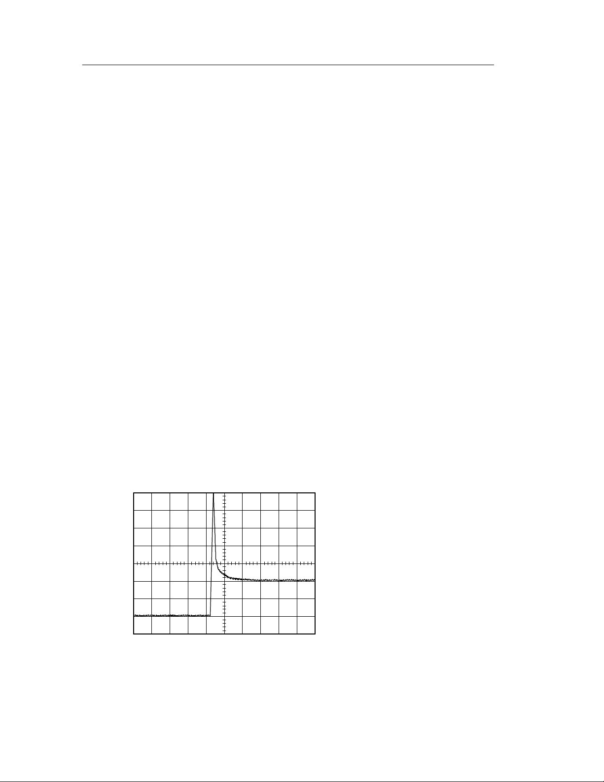
Optimizing the Acquisition
The initial acquisition shows the relay contact beginning to open at
the trigger point. This is followed by a large spike that indicates
contact bounce and inductance in the circuit. The induc tance can
cause contact arcing and premature relay failure.
You can use the vertical, horizontal, and trigger controls to optimize
the settings before the next single-shot event is captured.
When the next acquisition is captured with the new settings (when
you push the SINGLE SEQ button again), you can see more detail
about the relay contact opening. You can now see t hat the contact
bounces several times as it opens.
TDS1000/2000-Series Digital Oscilloscope User Manual
57
Page 76
Application Examples
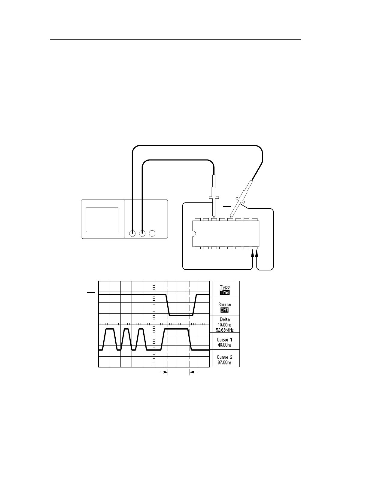
Measuring Propagation Delay
You suspect that the memory timing in a microprocessor circuit is
marginal. Set up the oscilloscope to measure the propagation delay
between the chip-selec t signal and the data output of the memory
device.
CS
Data
Data CS
CH 1 CH 2
58
TDS1000/2000-Series Digital Oscilloscope User Manual
Page 77

Application Examples
To set up to measure propagation dela y, follow these steps:
1. If the channels are not displayed, push the CH 1 MENU and then
CH 2 MENU buttons.
2. Push the AUTOSET button to trigger a stable display.
3. Adjust the horizontal and vertical controls to optimize the
display.
4. Push the CURSOR button to see the Cursor Menu.
5. Push the Type option button and select Time.
6. Push the Source option button and select CH1.
7. Turn the CURSOR 1 knob to place the cursor on the active edge
of the chip-select signal.
8. Turn the CURSOR 2 knob to place the second cursor on the data
output transition.
9. Read the propagation delay in the Delta readout in the Cursor
Menu.
TDS1000/2000-Series Digital Oscilloscope User Manual
59
Page 78
Application Examples
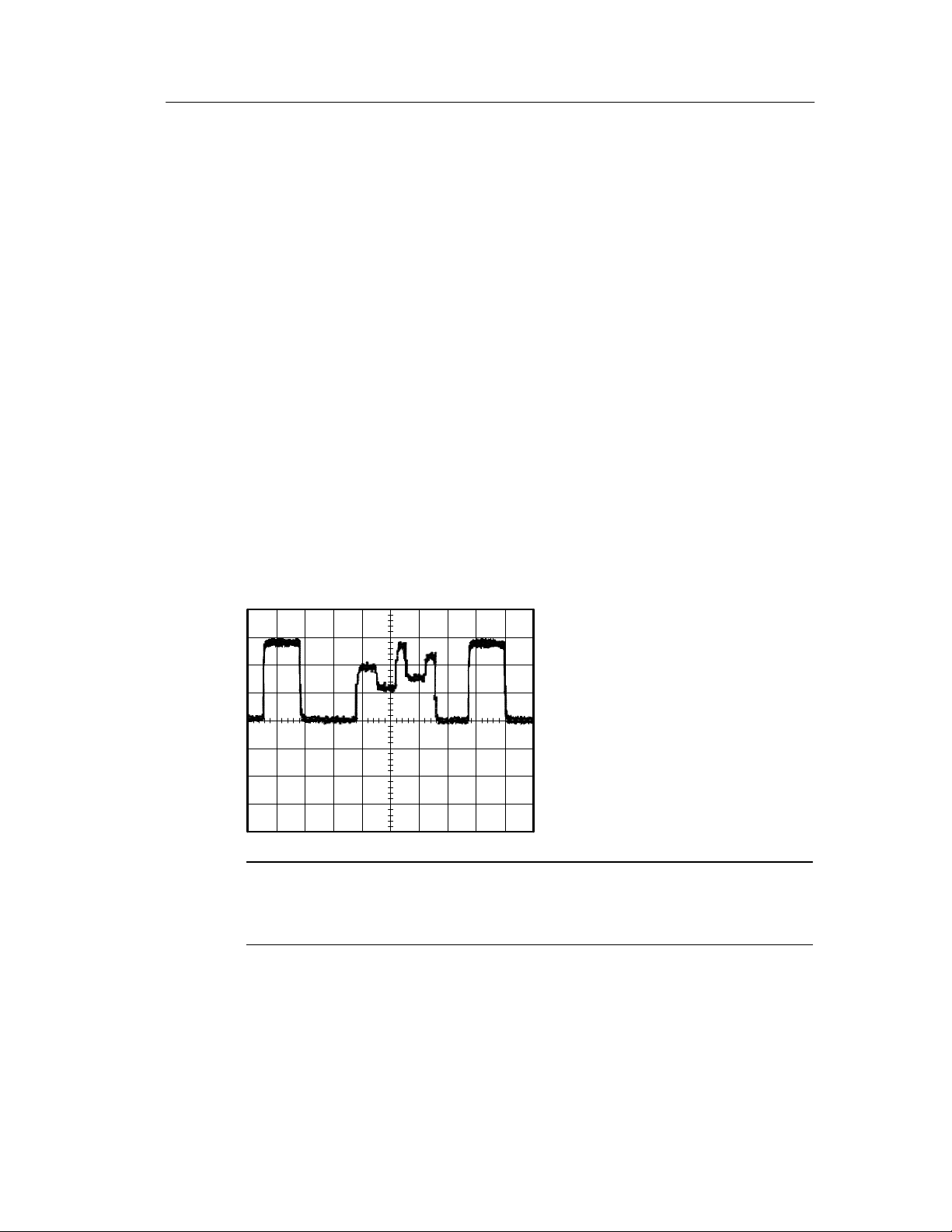
Triggering on a Specific Pulse Width
You are testing the pulse widths of a signal in a circuit. It is critical
that the pulses all be a specific width and you need to verify that they
are. Edge triggering shows that your signal is as specified, and the
pulse width measurement does not vary from the specifica tion.
However, you think there might be a problem.
To set up a test for pulse width aberrations, follow these steps:
1. Display the suspect signal on Ch 1. If Ch1 is not displayed, push
the CH1 MENU button.
2. Push the AUTOSET button to trigger a stable display.
3. Push the Single Cycle option button i n the AUTOSET Menu to
view a single cycle of the signal, and to qui ckly take a Pulse
Width measurement.
4. Push the TRIG MENU button.
5. Push the Type option button to select Pulse.
60
TDS1000/2000-Series Digital Oscilloscope User Manual
Page 79
Application Examples
6. Push the Source option button to select CH1.
7. Turn the TRIGGER LEVEL knob to set the trigger level near
the bottom of the signal.
8. Push the When option button to select = (equal).
9. Push the Set Pulse Width option button, and turn the USER
SELECT knob to set the pulse width to the value reported by the
Pulse Width measurement in step 3.
10. Push -- m o r e -- p a g e 1 o f 2 and set the Mode option to Normal.
You should achieve a stable display with the oscilloscope
triggering on normal pulses.
11. Push the When option button to select ¸, <,or>. If there are
any aberrant pulses that meet the specified When condition, the
oscilloscope triggers.
NOTE. The trigger frequency readout shows the frequency of events
the oscilloscope considers to be triggers, and may be less than the
frequency of the input signal in Pulse Width trigger mode.
TDS1000/2000-Series Digital Oscilloscope User Manual
61
Page 80

Application Examples
Triggering on a Video Signal
You are testing the video circuit in a piece of medical equipment and
need to display the video output signal. The video output is an NTSC
standard signal. Use the video trigger to obtain a stable display.
75 Ω terminator
CH 1
62
TDS1000/2000-Series Digital Oscilloscope User Manual
Page 81

Application Examples
NOTE. Most video systems use 75 ohm cabling. The oscilloscope
inputs do not properly terminate low impedance cabling. To avoid
amplitude inaccuracy from improper loading and reflections, place a
75 ohm fe edthrough terminator (Tektronix part number 011--0055--02
or equivalent) between the 75 ohm coaxial cable from the signal
source and the oscilloscope BNC input.
Triggering on Video Fields
Automatic. To trigger on the video fields, follow these steps:
1. Push the AUTOSET button. When Autoset is complete, the
oscilloscope displays the video signal with sync on All Fields.
2. Push the Odd Field or Even Field option buttons from the
AUTOSET Menu to sync on odd or even fields only.
Manual. An alternative method requires more steps, but may be
necessary depending on the video signal. To use the method, follow
these steps:
1. Push the TRIG MENU button to see the Trigger Menu.
2. Push the top option button and select Video.
3. Push the Source option button and select CH1.
4. Push the Sync option button and select All Fields, Odd Field,or
Even Field.
5. Push the Standard option button and select NTSC.
6. Turn the horizontal SEC/DIV knob to see a complete field across
the screen.
7. Turn the vertical VOLTS/DIV knob to ensure that the entire
video signal is visible on the screen.
TDS1000/2000-Series Digital Oscilloscope User Manual
63
Page 82

Application Examples
Triggering on Video Lines
Automatic. You can also look at the video lines in the field. To trigger
on the video lines, follow these steps:
1. Push the AUTOSET button.
2. Push the top option button to select Line to sync on all lines.
(The AUTOSET Menu includes All Lines and Line Number
options.)
Manual. An alternative method requires more steps, but may be
necessary depending on the video signal. To use the method, follow
these steps:
1. Push the TRIG MENU button to see the Trigger Menu.
2. Push the top option button and select Video.
3. Push the Sync option button and select All Lines.orLine
Number andturntheUSER SELECT knob to set a specific li ne
number.
4. Push the Standard option button and select NTSC.
5. Turn the SEC/DIV knob to see a complete video line across the
screen.
6. Turn the VOLTS/DIV knob to ensure that the entire video signal
is visible on the screen.
64
TDS1000/2000-Series Digital Oscilloscope User Manual
Page 83

75 Ω terminator
CH 1
Application Examples
Incoming video signal
TDS1000/2000-Series Digital Oscilloscope User Manual
65
Page 84

Application Examples
Using the Window Function to See Waveform Details
You can use the window function to examine a specific portion of a
waveform without changing the main display.
If you want to view the color burst in the previous waveform in more
detail without changing the main display, follow these steps:
1. Push the HORIZ MENU button to see the Horizontal Menu and
select the Main option.
2. Push the Window Zone option button.
3. Turn the SEC/DIV knob and select 500 ns. This will be the
SEC/DIV setting of the expanded view.
4. Turn the HORIZONTAL POSITION knob to position the
window around t he portion of the waveform that you want to
expand.
66
TDS1000/2000-Series Digital Oscilloscope User Manual
Page 85

Application Examples
5. Push the Window option button to see the expanded portion of
the waveform.
6. Turn the SEC/DIV knob to optimize viewing the expanded
waveform.
To switch between the Main and Window views, push the Main
or Window option button in the Horizontal Menu.
TDS1000/2000-Series Digital Oscilloscope User Manual
67
Page 86

Application Examples
Analyzing a Differential Communication Signal
You are having intermittent problems with a serial data communication link, and you suspect poor signa l quality. Set up the oscilloscope
to show you a snapshot of the serial data stream so you can veri fy the
signal levels and transition times.
Because this is a differential signal, you use the math function of the
oscilloscope to view a better representation of the waveform.
CH 1 CH 2
68
TDS1000/2000-Series Digital Oscilloscope User Manual
Page 87

Application Examples
NOTE. Be sure to first compensate both probes. Differences in probe
compensation appear as errors in the differential signal.
To activate the differential signals connected to channel 1 and
channel 2, follow these steps:
1. Push the CH 1 MENU but ton and set the Probe option attenua-
tion to 10X.
2. Push the CH 2 MENU but ton and set the Probe option attenua-
tion to 10X.
3. Set the switches to 10X on the P2200 probes.
4. Push the AUTOSET button.
5. Push the MATH MENU buttontoseetheMathMenu.
6. Push the Operation option button and select -- .
7. Push the CH1--CH2 option button to display a new waveform
that is the difference between the displayed waveforms.
8. You can adjust the vertical scale and position of the Math
waveform. To do so, follow these steps:
a. Remove the channel 1 and channel 2 waveforms from the
display.
b. Turn the CH 1 and CH 2 VOLTS/DIV and VERTICAL
POSITION knobs to adjust the vertical scale and position.
TDS1000/2000-Series Digital Oscilloscope User Manual
69
Page 88

Application Examples
For a m ore stable display, push the SINGLE SEQ button to control
the acquisition of the waveform. Each time you push the SINGLE
SEQ button, the oscilloscope acquires a snapshot of the digital data
stream. You can use the cursors or automatic measurements to
analyze the waveform, or you can store the waveform to analyze
later.
NOTE. Vertical sensitivity should match on waveforms used for math
operations. If they do not match, and you use cursors to measure the
waveform result, a U displays that represents unknown in the level
and delta readouts.
Viewing Impedance Changes in a Network
You have designed a circuit that needs to operate over a wide
temperature range. You need to evaluate the change in impedance of
the circuit as the ambient temperature is changed.
Connect the oscilloscope to monitor the input and output of the
circuit and capture the changes that occur as you vary the temperature.
70
TDS1000/2000-Series Digital Oscilloscope User Manual
Page 89

CH 1 CH 2
Application Examples
Circuit
In Out
TDS1000/2000-Series Digital Oscilloscope User Manual
71
Page 90

Application Examples
To view the input and output of the circuit in an XY display, follow
these steps:
1. Push the CH 1 MENU but ton and set the Probe option
attenuation to 10X.
2. Push the CH 2 MENU but ton and set the Probe option
attenuation to 10X.
3. Set the switches to 10X on the P2200 probes.
4. Connect the channel 1 probe to the input of the network, and
connect the channel 2 probe to the out put.
5. Push the AUTOSET button.
6. Turn the VOLTS/DIV knobs to display approximatel y the same
amplitude signals on each channel.
7. Push the DISPLAY button.
8. Push the Format option button and select XY.
The oscilloscope displays a Lissajous pattern representing the
input and output characteristics of the circuit.
9. Turn the VOLTS/DIV and VERTICAL POSITION knobs to
optimize the display.
10. Push the Persist option button and select Infinite.
11. Push the Contrast Increase or Contrast Decrease option buttons
to adjust the contrast of the screen.
As you adjust the ambient temperature, the display persistence
captures the changes in the characteristics of the circuit.
72
TDS1000/2000-Series Digital Oscilloscope User Manual
Page 91

Reference
This chapter describes the menus and operating details associated with
each front- panel menu button or control.
Topic Page
Acquire: menu, RUN/STOP button and SINGLE SEQ button 74
Autoset 79
Cursors 84
Default setup 85
Display 86
Help 89
Horizontal controls: menu, SET TO ZERO button, HORIZONTAL POSITION knob
and SEC/DIV knob
Math 93
Measure 94
Print 96
Probe check 96
Save/Recall 97
Trigger controls: menu, SET TO 50% button, FORCE TRIG button, TRIG VIEW
button and LEVEL (or U SER SELECT) knob
Utility 110
Vertical controls: menu, VERTICAL POSITION knobs and VOLTS/DIV knobs 112
90
99
TDS1000/2000-Series Digital Oscilloscope User Manual
73
Page 92
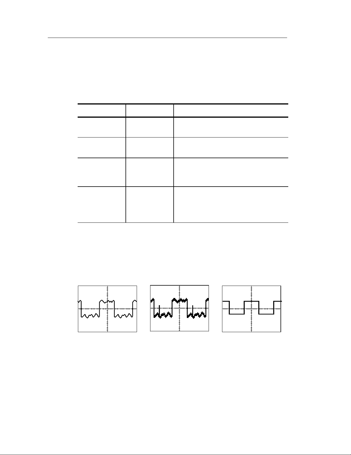
Reference
Acquire
Push the ACQUIRE button to set acquisition parameters.
Options Settings Comments
Sample Use to acquire and accurately display
most waveforms; this is the default mode
Peak Detect Use to detect glitches and reduce the
possibility of aliasing
Average Use to reduce random or uncorrelated
noise in the signal display; the number of
averages is selectable
Averages 4
16
64
128
Select number of averages
Key Points
If you probe a noisy square wave signal that contains intermittent,
narrow glitches, the waveform displayed will vary depending on the
acquisition mode you choose.
Sample Peak Detect Average
74
TDS1000/2000-Series Digital Oscilloscope User Manual
Page 93
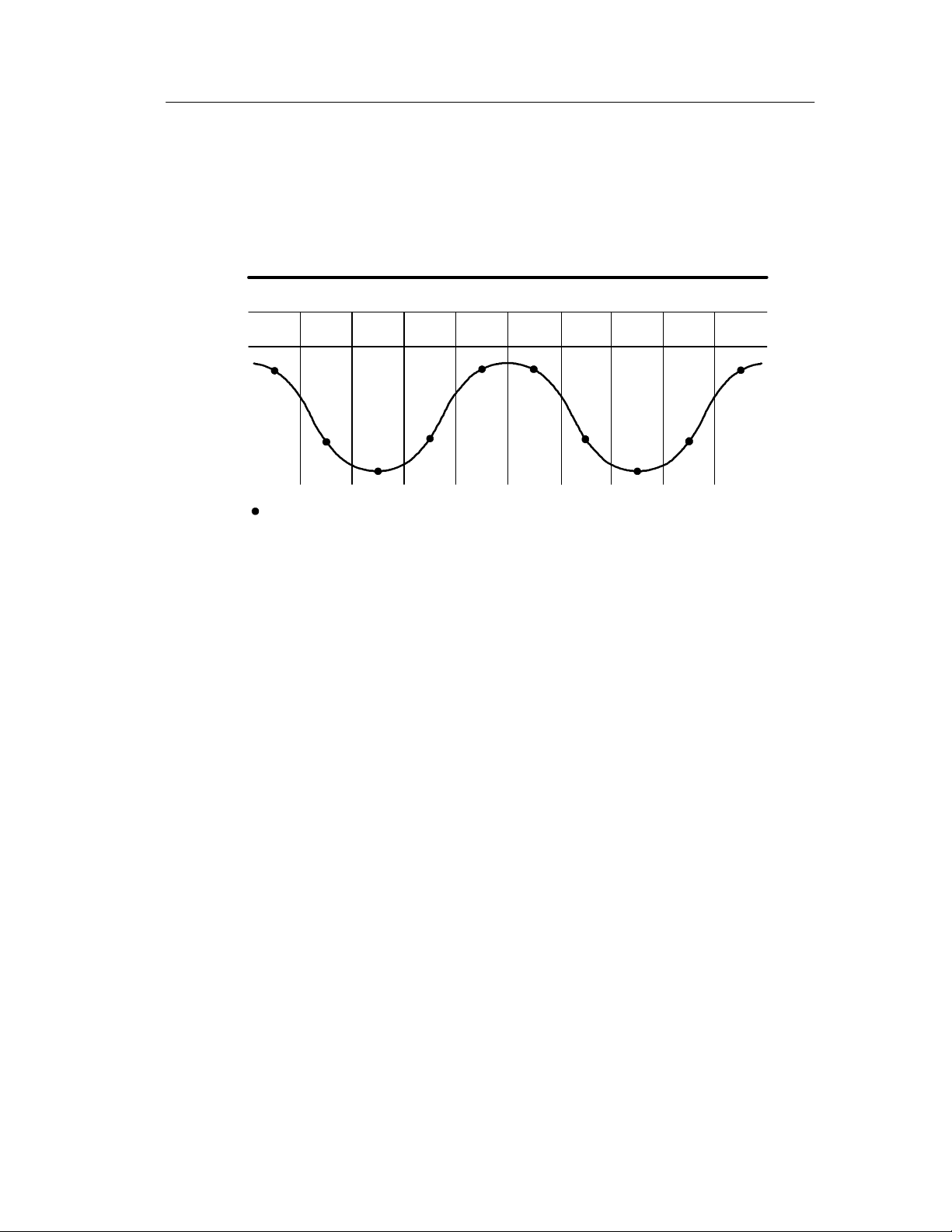
Reference
Sample. Use Sample acquisition mode to acquire 2500 points and
display them at the SEC/DIV setting. Sample mode is the default
mode.
Sample acquisition intervals (2500)
12345678910
Sample points
Sample mode acquires a single sample point in each interval.
The maximum sample rate is 1 GS/s for oscilloscope models with a
bandwidth of 60 MHz or 100 MHz and 2 GS/s for the 200 MHz
models. At 100 ns and faster settings, this sample rate does not
acquire 2500 points. In this case, a Digital Signal Processor
interpolates points between the sampled points t o make a full 2500
point waveform record.
TDS1000/2000-Series Digital Oscilloscope User Manual
75
Page 94

Reference
Peak Detect. Use Peak Detect acquisition mode to detect glitches as
narrow as 10 ns and to limit the possibility of aliasing. This mode is
effective when at the SEC/DIV setting of 5 s/div or slower.
Peak Detect acquisition intervals (1250)
12 345
Sample points displayed
Peak Detect mode displays the highest and lowest acquired voltage in each
interval.
NOTE. If you set the SEC/DIV setting to 2.5 s/div or f aster, the
acquisition mode changes to Sample because the sample rate is fast
enough that Peak Detect is not necessary. The oscilloscope does not
display a message to tell you that the mode was changed to Sample.
76
TDS1000/2000-Series Digital Oscilloscope User Manual
Page 95

Reference
When there is enough waveform noise, a typical peak detect display
shows large blac k areas. The TDS1000- and TDS2000-series
oscilloscopes display this area with diagona l lines to improve display
performance.
Typical peak detect display
Average. Use Average acquisition mode to reduce random or
TDS1000/TDS2000 peak detect display
uncorrelated noise in the signal you want to display. Data is acquired
in sample mode, then a number of waveforms are averaged together.
Select the number of acquisitions (4, 16, 64, or 128) to average for
the waveform.
RUN/STOP Button. Push the RUN/STOP button when you want the
oscilloscope to continuously acquire waveforms. Push the but ton
again to stop the acquisition.
SINGLE SEQ Button. Push the SINGLE SEQ button when you want the
oscilloscope to acquire a single waveform and then stop. Each time
you push the SINGLE SEQ button, the oscilloscope begins to acquire
another waveform. After the oscilloscope detects a trigger it
completes the acquisition and stops.
TDS1000/2000-Series Digital Oscilloscope User Manual
77
Page 96

Reference
Acquisition mode SINGLE SEQ button
Sample, Peak Detect Sequence is complete w hen one acquisition is acquired
Average Sequence is complete when the defined number of
acquisitions is reached (refer to page 74)
Scan Mode Display. You can use the Horizontal Scan acquisition mode
(also called Roll mode) to continuously monit or signals that change
slowly. The oscilloscope displays waveform updates from the left to
the right of the screen and erases old points as it displays new points.
A moving, one-division-wide blank section of the screen separates
the new waveform points from the old.
The oscilloscope changes to the Scan acquisition mode when you
turn the SEC/DIV knob to 100 ms/div or slower, and select the Auto
Mode option in the TRIGGER Menu.
To disable Scan mode, push the TRIG MENU button and set the
Mode option to Normal.
Stopping the Acquisition. While the acquisition is running, the
waveform display is live. Stopping the acquisition (when you push
the RUN/STOP button) freezes the display. In either mode, the
waveform display can be scaled or positioned with the vertical and
horizontal controls.
78
TDS1000/2000-Series Digital Oscilloscope User Manual
Page 97

Autoset
Reference
When you push the AUTOSET button, the oscilloscope identifies the
type of waveform and adjusts controls to produce a usable display of
the input signal.
Function Setting
Acquire mode Adjusted to Sample or Peak Detect
Display format Set to YT
Display type Set to Dots for a video signal, set to Vectors
for an FFT spectrum; otherwise, unchanged
Horizontal position Adjusted
SEC/DIV Adjusted
Trigger coupling Adjusted to DC, Noise Reject, or HF Reject
Trigger holdoff Minimum
Trigger level Set to 50%
Trigger mode Auto
Trigger source Adjusted; refer to page 80; cannot use Autoset
on the EXT TRIG signal
Trigger slope Adjusted
Trigger type Edge or Video
Trigger Video Sync Adjusted
Trigger Video Standard Adjusted
Vertical bandwidth Full
Vertical coupling DC (if GND was previously selected); AC for a
video signal; otherwise, unchanged
VOLTS/DIV Adjusted
TDS1000/2000-Series Digital Oscilloscope User Manual
79
Page 98

Reference
The Autoset function examines all channels for signals and displays
corresponding waveforms.
Autoset determines the trigger source based on the following
conditions:
H If multiple channels have signals, channel with the lowest
frequency signal
H No signals found, the lowest-numbered channel displayed when
Autoset was i nvoked
H No signals found and no channels displayed, oscilloscope
displays and uses channel 1
80
TDS1000/2000-Series Digital Oscilloscope User Manual
Page 99

Reference
Sine Wave
When you use the Autoset function and the oscilloscope determines
that the signal is similar to a sine wave, the oscilloscope displays the
following options:
Sine wave
options
Multi-cycle sine
Single-cycle sine
Details
Displays several cycles with appropriate vertical and
horizontal scaling; the oscilloscope displays Cycle RMS,
Frequency, Period, and Peak-to-Peak automatic measurements
Sets the horizontal scale to display about one cycle of the
waveform; the oscilloscope displays Mean, and Peak-toPeak automatic measurements
Converts the input time-domain signal into its frequency
components and displays the result as a graph of frequency
FFT
Undo Setup Causes the oscilloscope to recall the previous setup
versus magnitude (spectrum); since this is a mathematical
calculation, refer to the Math FFT chapter on page 115 for
more information
TDS1000/2000-Series Digital Oscilloscope User Manual
81
Page 100

Reference
Square Wave or Pulse
When you use the Autoset function and the oscilloscope determines
that the signal is similar to a square wave or pulse, the oscilloscope
displays the following options:
Square wave or
pulse options
Multi-cycle square
Single-cycle square
Details
Displays several cycles with appropriate vertical and
horizontal scaling; the oscilloscope displays Pk-Pk,
Mean, Period, and Frequency automatic measurements
Sets the horizontal scale to display about one cycle of
the waveform; the oscilloscope displays Min, Max, Mean,
and Positive Width automatic measurements
Displays the edge, and the Rise Time and Peak-to-Peak
automatic measurements
Rising edge
Displays the edge, and the Fall Time and Peak-to-Peak
automatic measurements
Falling edge
Undo Setup Causes the oscilloscope to recall the previous setup
82
TDS1000/2000-Series Digital Oscilloscope User Manual
 Loading...