

Page 1

xx
TBS1000B/EDU, TBS1000, TDS2000C/TDS1000C-EDU,
TDS2000B/TDS1000B, TDS2000/TDS1000, TDS200 and
ZZZ
TPS2000B/TPS2000 Series Digital Oscilloscopes
Programmer
*P077044403*
077-0444-03
Page 2

Page 3

xx
TBS1000B/EDU, TBS1000, TDS2000C/TDS1000C-EDU,
TDS2000B/TDS1000B, TDS2000/TDS1000, TDS200 and
ZZZ
TPS2000B/TPS2000 Series Digital Oscilloscopes
Programmer
Revision A 20170113
www.tek.com
077-0444-03
Page 4

Copyright © Tektronix. All rights reserved. Licensed software products are owned by Tektronix or its subsidiaries
or suppliers, and are protected by national copyright laws and international treaty provisions.
Tektronix products are covered by U.S. and foreign patents, issued and pending. Information in this publication
supersedes that in all previously published material. Specifications and price change privileges reserved.
TEKTRONIX and TEK are registered trademarks of Tektronix, Inc.
OpenChoice® is a registered trademark of Tektronix Inc.
Tektronix is an authorized licensee of the CompactFlash® trademark.
PictBridge is a trademark of the Standard of Camera & Imaging Products Association CIPA DC-001-2003 Digital
Photo Solutions for Imaging Devices.
Contacting Tektronix
Tektronix, Inc.
14150 SW Karl Braun Drive
P.O. B o x 500
Beaverton, OR 97077
USA
For product information, sales, service, and technical support:
In North America, call 1-800-833-9200.
Worldwide, visit www.tek.com to find contacts in your area.
Page 5

Table of Contents
Preface .............................................................................................................. iii
Related Documents ........................................................................................... iv
Conventions .................................................................................................. vii
Getting Started
Getting Started . ..... . ..... . ..... . ..... . ..... . ..... . ... . . . .... . ..... . ..... . ..... . ..... . ..... . ..... . ... . . ..... . ..... 1-1
Syntax and Commands
Command Syntax........................................ .................................. ....................... 2-1
Command Syntax............................................................................................ 2-1
Command and Query Structure ............................................................................ 2-2
Command Entry.............................................................................................. 2-4
Constructed Mnemonics .................................................................................... 2-6
Argument Types......... ................................ ................................ ..................... 2-7
Command Groups .............................................................................................. 2-11
Acquisition Commands .... . . .... . ..... . ..... . ..... . ..... . ..... ..... . ..... . ..... . ..... . ..... . ... . . . .... . .. 2-11
Calibration and Diagnostic Commands .. ................................ ............................... 2-11
Counter Commands (TBS1000B/EDU models only).................................................. 2-12
Cursor Commands ......................................................................................... 2-12
Data Logging Commands (Available Only On TBS1000B, TBS1000 and TDS2000C Series
Models) ... ................................ .................................. ........................... 2-13
Display Commands........................................................................................ 2-13
FFT Commands (TBS1000B/EDU models only)...................................................... 2-15
File System Commands (TBS1000B/EDU, TBS1000, TDS2000C, TDS1000C-EDU, TDS2000B,
TDS1000B, TDS2MEM Module, TPS2000B, and TPS2000 Only) .. . ..... . ..... . ..... . ..... . . 2-15
Hard Copy Commands .................................................................................... 2-17
Horizontal Commands .................................................................................... 2-17
Limit Test Commands (Available Only On TBS1000B, TBS1000 and TDS2000C Series
Models) ... ................................ .................................. ........................... 2-18
Math Commands........................................................................................... 2-20
Measurement Commands ................................................................................. 2-22
Miscellaneous Commands................................................................................ 2-23
PictBridge Commands (TBS1000B/EDU, TBS1000, TDS2000C, TDS1000C-EDU, TDS2000B, and
TDS1000B Only) ..................................................................................... 2-24
Power and Battery-Related Commands (TPS2000B and TPS2000 Only) .......................... 2-25
Power Measurement (TPS2000B/TPS2000 with TPS2PWR1 Power Analysis Application Key
Installed Only)................ ................................ ................................ ......... 2-25
RS-232 Commands (TDS2000, TDS1000, TDS200, TPS2000B, and TPS2000 Only) ... . ... . . . . 2 -28
TBS1000/B/EDU, TDS2000/B/C, TDS1000/B/C-EDU, TDS200, TPS2000/B Series Programmer i
Page 6

Table of Contents
Save and Recall
Status and Error Commands .............................................................................. 2-29
Trend Plot Commands (TBS1000B models only)...................................................... 2-30
Trigger Commands ........................... ................................ ............................. 2-30
Vertical Commands........................................................................................ 2-32
Waveform Commands................................ .................................. ................... 2-32
Zoom Comman
Command Descriptions ........................................................................................ 2-39
Manual Conventions................ ................................ .................................. ..... 2-39
Commands.............................................................................. 2-28
ds (TBS1000B/EDU models only) ............... ................................ ..... 2-36
Status and Events
Status a
nd Events ...... ................................ ................................ ........................... 3-1
Registers ..................... ................................ .................................. ............... 3-1
Queues ........................................................................................................ 3-4
Event Handling Sequence................................................................................... 3-5
Synchronization Methods.......................... .................................. ....................... 3-7
Programming Examples
Programming Examples .......................... ................................ ............................... 4-1
Appendices
endix A: ASCII Code Chart ................. ................................ .............................. A-1
App
Appendix B: Factory Setup..................................................................................... B-1
TBS1000, TDS2000C, TDS1000C-EDU, TDS2000B, and TDS1000B Series Oscilloscopes. . . .. B-1
TPS2000 Series Oscilloscopes . . .... . ..... . ..... . ..... . ..... . ... . . ..... . ..... . ..... . ... . . . .... . ..... . ..... B-2
TPS2000B Series Oscilloscopes .. . ..... . ..... . ..... . ... . . ..... . ..... . ..... . ..... . ..... . ..... . ..... . ..... . B-4
TDS1000 and TDS2000 Series Oscilloscopes. ... . . . .... . ..... . ..... . .... . ..... . ..... . .... . . .... . ..... . . B-5
DS210 and TDS220 Oscilloscopes .. . ..... . ..... . ..... . ..... . ... . . . .... . . .... . ..... . ..... . ..... . ..... . . B-7
T
TDS224 Oscilloscopes . ..... . ..... . ..... . ..... . ..... . ..... . ..... . ..... . ..... . ..... . ..... . ..... . ..... . ... . . . B-8
Appendix C: Reserved Words.................................................................................. C-1
Glossary
ii TBS1000/B/EDU, TDS2000/B/C, TDS1000/B/C-EDU, TDS200, TPS2000/B Series Programmer
Page 7

Preface
This programmer manual provides information on how to remotely operate your
oscilloscope. You can use communication ports and protocols, such as for the
RS-232, the G
(USB) standards, to remotely control and operate your oscilloscope.
eneral Purpose Interface Bus (GPIB), or Universal Serial Bus
This docume
TBS1000B/EDU Series instructions, any version
TBS1000 Series instruments, any version
TPS2000 and TPS2000B Series instruments, any version.
TDS1000C-EDU, any version.
TDS2000C Series instruments, any version.
TDS1000
TDS2CMorTDS2CMA,anyversion,whenusedinTDS1000orTDS2000
Series
TDS2MEM any version, when used in most TDS1000 or TDS2000 Series
instr
TDS2CM, TDS2CMA, or TDS2MM any version, when used in a
TDS2
TDS2CM or TDS2CMA version CMV:v1.04 and above, or TDS2MM any
ver
above.
nt supports the following products:
B and TDS2000B Series instruments, any version.
instruments, any version.
uments (except TDS1001 and TDS2004 models), any version.
24 instrument, any version.
sion, when used in TDS210 and TDS220 instruments with FV:v1.09 and
TBS1000/B/EDU, TDS2000/B/C, TDS1000/B/C-EDU, TDS200, TPS2000/B Series Programmer iii
Page 8

Preface
Related Documents
Each series of oscilloscopes has a different set of documentation.
TBS1000B/EDU Series
Manuals
TBS1000 S eries Manuals
Language
English 077-0886-XX
French 077-0887-XX
Italian 077-0888-XX
German
Spanish
Japanese 077-0891-XX
Portuguese 077-0892-XX
Simplified Chinese
Traditional Chinese
Korean 077-0895-XX
Russian 077-0896-XX
Language
English 077-0760-XX
French 077-0761-XX
Italian 077-0762-XX
German
Spanish
Japanese 077-0765-XX
Portuguese 077-0766-XX
Simplified Chinese
Traditional Chinese
Korean 077-0769-XX
Russian 077-0770-XX
TBS user manual part number
077-0889-XX
077-0890-XX
077-0893-XX
077-0894-XX
TBS user manual part number
077-0763-XX
077-0764-XX
077-0767-XX
077-0768-XX
TPS2000 and TPS2000B
Series Manuals
For general operation, refer to your product user manual, a standard accessory,
listed in the following table.
Language
English 071-1441-XX 071-2722-XX
French 071-1442-XX 071-2723-XX
TPS user manual part number
TPS2000 Series TPS2000B Series
iv TBS1000/B/EDU, TDS2000/B/C, TDS1000/B/C-EDU, TDS200, TPS2000/B Series Programmer
Page 9

Preface
Language
Italian 071-1443-XX 071-2724-XX
German
Spanish
Japanese 071-1446-XX 071-2727-XX
Portuguese 071-1447-XX 071-2728-XX
Simplified Chinese
Traditional Chinese
Korean 071-1450
Russian 071-1451-XX 071-2732-XX
TPS user manual part number
TPS2000 Series TPS2000B Series
071-1444-XX 071-2725-XX
071-1445-XX 071-2726-XX
071-1448-
071-1449-
XX
XX
-XX
071-2729-
071-2730-
071-2731
XX
XX
-XX
For information o n the TPS2PWR1 Power Analysis Application, refer to the
TPS2PW
R1 Power Analysis Application User Manual, an optional accessory
available in eleven languages.
Language
English 071-1452-XX
French 071-1453-XX
Italian 071-1454-XX
German
Spanish
Japanese 071-1457-XX
Portuguese 071-1458-XX
Simplified Chinese
Traditional Chinese
Korean 071-1461-XX
Russian 071-1462-XX
TPS2PWR1 user manual part number
071-1455-XX
071-1456-XX
071-1459-XX
071-1460-XX
TBS1000/B/EDU, TDS2000/B/C, TDS1000/B/C-EDU, TDS200, TPS2000/B Series Programmer v
Page 10

Preface
TDS1000, TDS2000,
TDS1000C-EDU, and
TDS2000C Series manuals
For general ope
ration, refer to the user manual for your product. For information
on the TDS2CMA Communications module, refer to the TDS1000 and TDS2000
Series Digital Storage Oscilloscope User Manual.
Language
English 071-1064-XX 071-1817-XX 071-2722-XX
French 071-1065-XX 071-1818-XX 071-2723-XX
Italian 071-1066-XX 071-1819-XX 071-2724-XX
German
Spanish
Japanese 071-1069-XX 071-1822-XX 071-2727-XX
Portuguese 071-1070-XX 071-1823-XX 071-2728-XX
Simplified Chinese
Traditional Chinese
Korean 071-1073-XX 071-1826-XX 071-2731-XX
Russian 071-1074-XX 071-1827-XX 071-2732-XX
User manual part number
TDS1000/TDS2000 TDS1000B/TDS2000B TDS1000C-EDU/TDS2000C
071-1067-XX 071-1820-XX 071-2725-XX
071-1068-XX 071-1821-XX 071-2726-XX
071-1071-XX 071-1824-XX 071-2729-XX
071-1072-XX 071-1825-XX 071-2730-XX
For information on the TDS2MEM Storage Memory and Communications
module, refer to the TDS2MEM Storage Memory and Communications Module
User Manual (071-1262-XX), an optional accessory that includes eleven
languages.
TDS200 Series Manuals
For general operation, refer to the TDS200 Series Digital Real-Time Oscilloscope
User Manual, a standard accessory.
Language
English 071-0398-XX
French 071-0400-XX
Italian 071-0401-XX
German
Spanish
Japanese 071-0405-XX
Portuguese 071-0403-XX
Simplified Chinese
Traditional Chinese
Korean 071-0408-XX
Russian 071-0404-XX
User manual part number
071-0402-XX
071-0399-XX
071-0406-XX
071-0407-XX
For information on the TDS2CMA Communications module, or TDS2MM
Math Measurements module, refer to the TDS200 Series Extension Modules
Instructions Manual (071-0409-XX), a standard accessory for extension modules
in English only.
vi TBS1000/B/EDU, TDS2000/B/C, TDS1000/B/C-EDU, TDS200, TPS2000/B Series Programmer
Page 11

Preface
Service Manuals (English
Only)
For informatio
manual from the following optional accessories:
TBS1000B/EDU
(077-0897-XX)
TBS1000 Series Digital Storage Oscilloscopes Service Manual
(077-0772-
TDS2000C and TDS1000C-EDU Series Digital Storage Oscilloscopes Service
Manual (07
TDS1000B and TDS2000B Series Digital Storage Oscilloscopes Service
Manual (0
TDS1000 and TDS2000 Series Digital Storage Oscilloscopes Service Manual
(071-10
TDS200 Series Digital Real-Time Oscilloscopes Service Manual
(071-0
TPS2000B Series Digital Storage Oscilloscopes Service Manual
(077-
TPS2000 Series Digital Storage Oscilloscopes Service Manual
(071-
n on how to service your oscilloscope, refer to the appropriate
Series Digital Storage Oscilloscopes Service Manual
XX)
7-0446-XX)
77-0356-XX)
76-XX)
492-XX)
4447-XX)
1465-XX) or (077-0306-00)
Conventions
er to Command Syntax for information about command conventions. (See
Ref
page 2-1.)
s manual uses the following conventions:
Thi
References to the TDS2CMA Communications Extension Module include the
S2CM and TDS2CMAX modules.
TD
Command descriptions list specific oscilloscopes series (and modules) when
ommands are valid for only those products
c
TBS1000/B/EDU, TDS2000/B/C, TDS1000/B/C-EDU, TDS200, TPS2000/B Series Programmer vii
Page 12

Preface
viii TBS1000/B/EDU, TDS2000/B/C, TDS1000/B/C-EDU, TDS200, TPS2000/B Series Programmer
Page 13

Getting Started
Page 14

Page 15

Getting Started
This manual contains information on how to remotely control and operate your
oscilloscope through communications protocol and commands.
NOTE. For TB
S1000B/EDU, TBS1000, TDS2000C, TDS1000C-EDU, TDS2000B,
and the TDS1000B Series, you need to install the PC Communications software
from the CD that came with the oscilloscope on a PC before you connect the
oscilloscope USB Device port to the PC. Refer to the product user manual for
installation information.
For all products, you need to connect an appropriate cable between the
communications port on your oscilloscope and your PC.
The next table describes where the communications port is located on an extension
module or oscilloscope, and the function of the port.
Series Port location Port function
TDS200 TDS2CM, TDS2CMA,
or TDS2CMAX
nications, TDS2MM
Commu
Math
TDS1000/ TDS2000
1000B/EDU,
TBS
TBS1000, TDS2000C,
TDS1000C-EDU,
1000B, and
TDS
TDS2000B
TPS2000 and TPS2000B Back of oscilloscope RS-232, Centronics
1
2
2
TDS1001 and TDS2004 are not compatible with the TDS2MEM module.
stall the PC Communications software from the CD that came with the oscilloscope first,andthenreferto
In
your product user manual for information on installing the software. After the software is installed, connect
the oscilloscope to a PC.
1
TDS2CMA or TDS2CMAX
TDS2MEM Storage Memory
ommunications
and C
k of o s cil loscope
Bac
RS-232, Centronics, GPIB
RS-232, Centronics, GPIB
RS-232, Centronics,
actFlash
Comp
Device
USB
B with a TEK-USB-488
GPI
adapter
Refer to your oscilloscope user manual for information on how to install, test, and
configure your oscilloscope and module.
NOTE. The firmware for the TBS1000B/EDU, TBS1000, TDS2000C,
TDS1000C-EDU, TDS1000B, TDS2000B, TPS2000B, and TPS2000 Series
oscilloscopes includes communications, math, and storage memory functions.
TBS1000/B/EDU, TDS2000/B/C, TDS1000/B/C-EDU, TDS200, TPS2000/B Series Programmer 1-1
Page 16

Getting Started
TDS2CM,
TDS2CMA or
Series
TDS200
TDS1000 or
TDS2CMAX TDS2MM TDS2MEM TEK-USB-488
Yes Yes No No
Yes No Yes
1
No
TDS2000
TBS1000B/EDU,
No No No Yes
TBS1000,
TDS2000C,
TDS1000C-EDU,
TDS1000B or
TDS2000B
TPS2000 o
TPS2000B
1
2
r
2
TDS1001 and TDS2004 models are not compatible with the TDS2MEM module.
RS-232 is
No No No No
included in the oscilloscope firmware.
NOTE. If you use GPIB with the TBS1000B/EDU, TBS1000, TDS2000C,
TDS1000C-EDU, TDS2000B, or TDS1000B Series, you can set a unique GPIB
address for the oscilloscope through the UTILITY ► Options ► GPIB Setup
option.
1-2 TBS1000/B/EDU, TDS2000/B/C, TDS1000/B/C-EDU, TDS200, TPS2000/B Series Programmer
Page 17

Syntax and Commands
Page 18

Page 19

Command Syntax
You can control the oscilloscope through the GPIB, RS-232, or USB interface
using a large group of commands and queries.
This section describes the syntax these commands and queries use and the
conventions the oscilloscope uses to process them. The commands and queries
themselves are listed in the Command Descriptions section.
Command Syntax
Table 2-1: Oscilloscope communication protocol
Model or option GPIB RS-232 USB
TDS2CM,
TDS2CMA,
TDS2CMAX
TDS2MM
TDS2MEM
TDS1000 or
TDS2000
TBS1000B/EDU,
TBS1000,
TDS2000C,
TDS1000C-EDU,
TDS1000B, or
TDS2000B
TPS2000B,
TPS2000
1
2
3
Yes Yes No
Yes Yes No
No Yes No
1
Yes
3
Yes
No Yes No
Function available with a TDS2CM, TDS2CMA, or TDS2CMAX module.
Function available with a TDS2MEM module.
Function available with a TEK-USB-488 adapter.
12
Yes
No Yes
No
You transmit commands to the oscilloscope using the enhanced American
Standard Code for Information Interchange (ASCI
I) character encoding. Appendix
A contains a chart of the ASCII character set.
The Backus Naur Form (BNF) notation is used in this manual to describe
commands and queries.
Table 2-2: BNF notation
Symbol Meaning
<>
::=
| Exclusive OR
{ } Group; one element is required
Defined element
Is defined as
TBS1000/B/EDU, TDS2000/B/C, TDS1000/B/C-EDU, TDS200, TPS2000/B Series Programmer 2-1
Page 20

Command Syntax
Table 2-2: BNF notation (cont.)
Symbol Meaning
[]
.. .
( ) Comment
Command and Query Structure
Commands consist of set commands and query commands (usually simply called
commands and queries). Commands change oscilloscope settings or perform a
specific action. Queries cause the oscilloscope to return data and information
about its status.
Most commands have both a set form and a query form. The query form of the
command is the same as the set form except that it ends with a question mark. For
example, the set command ACQuire:MODe has a query form ACQuire:MODe.
Not all commands have both a set and a query form; some commands are set
only and some are query only.
Optional; can be omitted
Previous element(s) may be repeated
A few commands do both a set and query action. For example, the *CAL?
command runs a self-calibration program on the oscilloscope, then returns the
result of the calibration.
A command message is a command or query name, followed by any information
the oscilloscope needs to execute the command or query. Command messages
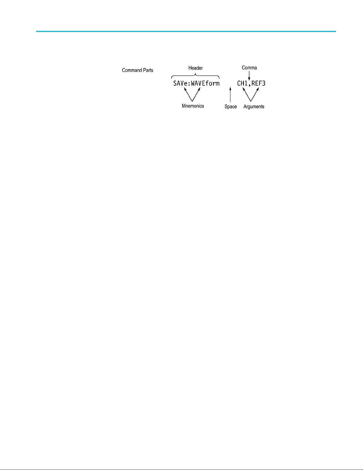
consist of five different element types.
Table 2-3: Command message elements
Symbol Meaning
<Header>
<Mnemonic>
<Argument> A quantity, quality, restriction, or limit associated with the header.
<Comma> A single comma between arguments of multiple-argument commands.
<Space>
The basic command name. If the header ends with a question mark,
the command is a query. The header may begin with a colon (:)
character; if the command is concatenated with other commands the
beginning colon is required. The beginning colon can never be used
with command headers beginning with a star (*).
A header subfunction. Some command headers have only one
mnemonic. If a command header has multiple mnemonics, they are
always separated from each other by a colon (:) character.
Not all commands have an argument, while other commands have
multiple arguments. Arguments are separated from the header by a
<Space>. Arguments are separated from each other by a <Comma>.
It may o ptionally have white space characters before and after the
comma.
A white space character between command header and argument. It
may optionally consist of multiple white space characters.
2-2 TBS1000/B/EDU, TDS2000/B/C, TDS1000/B/C-EDU, TDS200, TPS2000/B Series Programmer
Page 21
Command Syntax
Commands
The following fi
Figure 2-1: Command message elements
Commands cause the oscilloscope to perform a specific function or change one of
its settings. Commands have the structure:
[:]<Header>[<Space><Argument>[<Comma><Argument>]...]
A command header is made up of one or more m nemonics arranged in a
hierarchical or tree structure. The first mnemonic is the base or root of the tree
and each subsequent mnemonic is a level or branch off of the previous one.
Commands at a higher level in the tree may affect those at a lower level. The
g colon (:) always returns you to the base of the command tree.
leadin
gure shows the five command message elements.
Queries
Headers in Query
Responses
Queries cause the oscilloscope to return information about its status or settings.
Queries have the structure:
[:]<Header>
[:]<Header>[<Space><Argument>[<Comma><Argument>]...]
You can specify a query command at any level within the command tree unless
otherwise noted. These branch queries return information about all the mnemonics
below the specified branch or level.
For example, MEASUrement:MEAS<x>:UNIts? returns the measurement
units, while MEASUrement:MEAS<x>:TYPe? returns the measurement type
selected for t he measurement, and MEASUrement:MEAS<x>? returns all the
easurement parameters for the specified measurement.
m
You can control whether the oscilloscope returns headers as part of the query
response. Use the HEADer command to control this feature. If header is on, the
oscilloscope returns command headers as part of the query and formats the query
response as a valid set command. When header is off, the oscilloscope sends
back only the values in the response. This format can make it easier to parse and
extract the information from the response.
TBS1000/B/EDU, TDS2000/B/C, TDS1000/B/C-EDU, TDS200, TPS2000/B Series Programmer 2-3
Page 22

Command Syntax
Clearing the Output Queue
Command Entry
Table 2-4: Comp
Query Header Off response Header On response
ACQuire:NUMAVg
CHx1:COUPling DC CH1:COUPLING DC
To clear the output queue and reset the oscilloscope to accept a new c ommand or
query, send a Device Clear (DCL) from a GPIB host.
From an RS-232 host, send a break signal. The RS-232 interface responds by
returning the ASCII string "DCL."
From a USB host, send an INITIATE_CLEAR followed by
a C HECK_CLEAR_STATUS. The USB interface responds to
CHECK_CLEAR_STATUS with STATUS_SUCCESS when it is finished clearing
the output queue.
Follow these general rules when entering commands:
Enter commands in upper or lower case.
arison of Header Off and Header On responses
64
ACQUIRE:NUMAVG 64
Abbreviating Commands
Concatenating C ommands
You can precede any command with white space characters. White space
characters include any combination of the ASCII control characters 00 through
09 and 0B through 20 hexadecimal (0 through 9 and 11 through 32 decimal).
The oscilloscope ignores commands that consists of just a combination of
white space characters and line feeds.
You can abbreviate many oscilloscope commands. These abbreviations are shown
in capital letters in the command listing in the Command Groups section and
Command Descriptions section. For example, the command ACQuire:NUMAvg
can be entered simply as ACQ : NUMA or acq:numa.
If you use the HEADer command to have command headers included as part
of query responses, you can a lso control whether the returned headers are
abbreviated or are full-length using the VERBose command.
You can concatenate any combination of set commands and queries using a
semicolon (;). The oscilloscope executes concatenated commands in the order
received. When concatenating commands and queries you must follow these rules:
Completely different headers must beseparatedbybothasemicolonand
by the beginning colon on all commands but the first. For example, the
commands TRIGger:MODe NORMal and ACQuire:NUMAVg 16 can be
concatenated into a single command:
2-4 TBS1000/B/EDU, TDS2000/B/C, TDS1000/B/C-EDU, TDS200, TPS2000/B Series Programmer
Page 23

Command Syntax
TRIGger:MODe N
If concatenated commands have headers that differ by only the last
mnemonic, you
beginning colon. For example, the commands ACQuire:MODe AVErage and
ACQuire:NUMAVg 16 could be concatenated into a s ingle command:
ACQuire:MODe AVErag e; NUMAVg 16
The longer v
ACQuire:MODe AVErage;:ACQuire:NUMAVg 16
Never precede a star (*) command with a colon or semicolon:
ACQuire:MODe AVErage;*TRG
The oscilloscope processes commands that follow the star command as if
the star command was not there, so:
ACQuire:MODe AVErage;*TRG;NUMAVg 16
sets the acquisition mode to average and sets acquisition averaging to 16. The
*TRG command is ignored.
When you concatenate queries, the responses to all queries are combined into
a single response message. For example, if channel 1 coupling is set to DC
and the bandwidth is set to 20 MHz, the concatenated query:
ORMal;:ACQuire:NUMAVg 16
can abbreviate the second command and eliminate the
ersion works equally well:
CH1:COUPling;BANdwidth
returns CH1:COUPLING DC;:CH1:BANDWIDTH ON if header is on, or
DC;ON if header is off.
You can concatenate set commands and queries in the same message. For
example:
ACQuire:MODe AVErage;NUMAVg;STATE
s a valid message that sets the acquisition mode to average, queries the
i
number of acquisitions for averaging, and then queries the acquisition state.
The oscilloscope executes concatenated commands and queries in the order
it receives them.
Any query that returns arbitrary data, such as ID, must be the last query when
part of a concatenated command. If the query is not last, the oscilloscope
generates event message 440.
Here are some INVALID concatenation examples:
CH1:COUPling DC;ACQuire:NUMAVg 16 (missing colon before ACQuire)
CH1:COUPling DC;:BANDwidth ON (invalid colon before BANDwidth)
CH1:COUPling DC;:*TRG (invalid colon before a star (*) command)
TBS1000/B/EDU, TDS2000/B/C, TDS1000/B/C-EDU, TDS200, TPS2000/B Series Programmer 2-5
Page 24

Command Syntax
Message Terminators
HORizontal:MA
different; either remove the second occurrence of MAIn:, or put HORizontal:
in front of MAIN:SCAle)
This manual uses the term <EOM> (End of message) to represent a message
terminator.
GPIB End of Message (EOM) Terminators. GPIB EOM terminators can be the
END message (EOI asserted concurrently with the last data byte), the ASCII
code for line feed (LF) sent as the last data byte, or both. The oscilloscope
always terminates messages with LF and EOI. White space is allowed before the
terminator; for example, CR LF is acceptable.
USB End of Message (EOM) Terminators. The EOM bit must be set in the USB
header of the last transfer of a command message
See the USB Test and Measurement Class Specification (USBTMC) section
3.2.1 for details. The oscilloscope terminates messages by setting the EOM
bit in the USB header of the last transfer of a message to the host (USBTMC
Specification section 3.3.1), and by terminating messages with a LF. White space
is allowed before the terminator; for example, CR LF is acceptable.
RS-232 End of Message Terminators. RS-232 EOM terminators can be a CR
(carriage return), LF (line feed), CRLF (carriage return followed by a line feed),
or LFCR (line feed followed by a carriage return)
In:POSition 0;MAIn:SCAle 1E-13 (levels of mnemonics are
When receiving, the oscilloscope accepts all four combinations as valid input
message terminators regardless of the currently selected terminator. When a
combination of multiple characters is selected (CRLF or LFCR), the oscilloscope
interprets the first character as the terminator and the second character as a null
command.
Constructed Mnemonics
Some header mnemonics specify one of a range of mnemonics. For example, a
channel mnemonic could be CH2. You can use these mnemonics in the command
just as you do any other mnemonic. For example, there is a CH1:VOLts command
and there is also a CH2:VOLts command. In the command descriptions, this
list of c hoices is abbreviated CH<x>.
Channel mnemonics. Commands specify the channel to use as a mnemonic in
the header.
Symbol
CH<x> 2-channel models: A channel specifier; <x> is 1 or 2.
Meaning
4-channel models: A channel specifier; <x> is 1, 2, 3, or 4.
2-6 TBS1000/B/EDU, TDS2000/B/C, TDS1000/B/C-EDU, TDS200, TPS2000/B Series Programmer
Page 25

Command Syntax
Reference Waveform
Mnemonics
Waveform Mnemonics
Cursor Position Mnemonic
Commands can sp
ecify the reference waveform to use as a mnemonic in the
header.
Symbol Meaning
REF<x>
2-channel models: A reference waveform specifier; <x> is A or B.
4-channel models: A reference waveform specifier; <x> is A, B, C,
or D.
In some commands you can specify a waveform without regard to its type:
channel waveform, math waveform, or reference waveform. The "y" is the same
as "x" in Reference Waveform Mnemonics.
Symbol Meaning
<wfm> Can be CH<x>, MATH, or REF<y>
When the oscilloscope displays cursors, commands may specify which cursor
of the pair to use.
Symbol Meaning
POSITION<x>
A cursor selector;<x> is 1 or 2.
Measurement Specifier
Mnemonics
Argument Types
Commands can specify which measurement to set or query as a mnemonic in the
header. The oscilloscope can display up to four (TDS200) or five (TBS1000,
TDS2000C, TDS1000C-EDU, TDS2000B, TDS1000B, TDS2000, TDS1000,
TPS2000B, a nd TPS2000) or six (TBS1000B/EDU) automated measurements.
Symbol Meaning
MEAS<x> A measurement specifier; <x> is 1-4 (TDS200) or 1-5 (TBS1000,
TDS2000C, TDS1000C-EDU, TDS2000B, TDS1000B, TDS2000,
S1000, TPS2000B, and TPS2000) or 1-6 (TBS 1000B/EDU).
TD
A command argument can be in one of several forms. The individual descriptions
of each command tell which argument types to use with that command.
TBS1000/B/EDU, TDS2000/B/C, TDS1000/B/C-EDU, TDS200, TPS2000/B Series Programmer 2-7
Page 26

Command Syntax
Numeric Arguments
Many oscillosc
ope commands require numeric arguments.
Table 2-5: Types of numeric arguments
Symbol Meaning
<NR1>
<NR2> Floating po
<NR3> Floating point value with an exponent
Signed integer value
int value without an exponent
The syntax shown is the data format that the oscilloscope returns in response to
aquery.Th
is format is also the preferred format when sending a command to
the oscilloscope.
When you e
nter an incorrect numeric argument, the oscilloscope automatically
forces the numeric argument to a correct value.
Table 2-6: Oscilloscope handling of incorrect numeric arguments
Argument value
Numeric argument is less than lowest correct
value for that command
Numeric argument is greater than the highest
ct value for that command
corre
ic value is between two correct values
Numer
Oscilloscope response
Sets the specified command to the lowest
t value and executes the command
correc
he specified command to the highest
Sets t
correct value and executes the c ommand
s the entered value to the nearest
Round
correct value and executes the c ommand
Quoted String Arguments
Some commands accept or return data in the form of a quoted string, which is
simply a group of ASCII characters enclosed by single quotes (') or double quotes
("). For example:
"this is a quoted string"
Symbol Meaning
<QString> Quoted string of ASCII text
2-8 TBS1000/B/EDU, TDS2000/B/C, TDS1000/B/C-EDU, TDS200, TPS2000/B Series Programmer
Page 27

Command Syntax
Follow these ru
les when you use quoted strings:
1. A quoted string can include any character defined in the 7-bit ASCII character
set. (See page
A-1, ASCII Code Chart.).
2. Use the same type of quote character to open and close the string:
"this is a valid string"
3. You can mix quotation marks within a string if you follow the previous rule:
"this is an 'accepta ble' string"
4. You can include a quote character within a string simply by repeating the
quote. For example,
"hereisa""mark"
5. Strings
can have upper or lower case characters.
6. If you use a GPIB network, you cannot terminate a quoted string with the
END mes
sage before the closing delimiter.
7. A carriage return or line feed embedded in a quoted string does not terminate
ring, but is treated as just another character in the string.
the st
8. The maximum length of a quoted string returned from a query is 1000
cters.
chara
Block Arguments
Herearesomeexamplesofinvalidstrings:
"Invalid string argument' (quotes are not of the same type)
"test<EOI>" (termination character is embedded in the string)
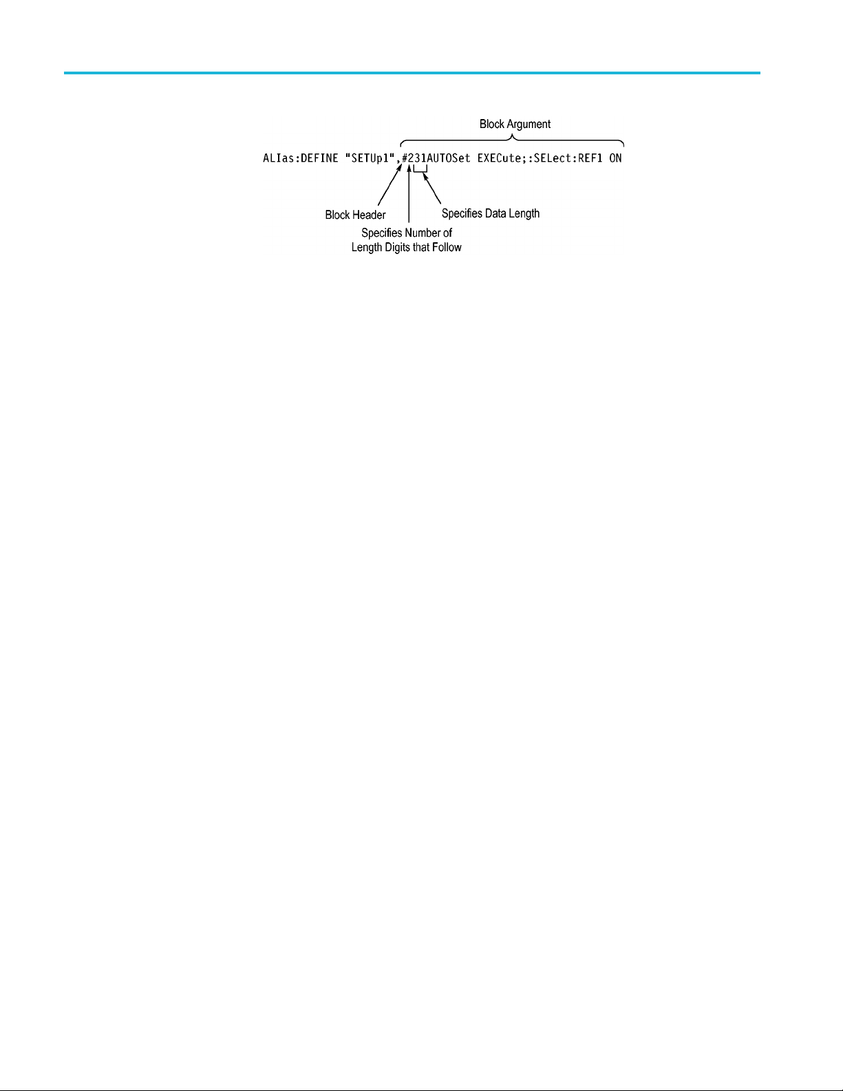
Several oscilloscope commands use a block argument form.
Table 2-7: Parts of a block argument
Symbol Meaning
<NZDig>
<Dig> A digit character, in the range 0-9
<DChar> A character with the hex equivalent of 00 through FF hexadecimal
<Block>
A nonzero digit character, in the range 1-9 Specifies the number of
<Dig> elements that follow
(0 through 255 decimal)
A block of data bytes, defined as:
<Block> := { #<NZDig><Dig>[<Dig>...][<DChar>...] |
#0[<DChar>...]<terminator> }
The following figure shows an example o f a block argument.
TBS1000/B/EDU, TDS2000/B/C, TDS1000/B/C-EDU, TDS200, TPS2000/B Series Programmer 2-9
Page 28
Command Syntax
Figure 2-2: Block argument example
<NZDig> specifies the number of <Dig> elements that follow. Taken together,
the <Dig> elements form a decimal integer that specifies how many <DChar>
elements follow.
#0 means that the <Block> is a n indefinite length block. The <terminator> ends
the block. You should not use indefinite length blocks with RS-232, because there
is no way to include a <terminator> character as a <DChar> character.
The first occurrence of a <terminator> character signals the end of the block and
any subsequent <DChar> characters will be interpreted as a syntax error. With
the GPIB, the EOI line signals the last byte. With the USB, the EOM bit signals
tbyte.
the las
2-10 TBS1000/B/EDU, TDS2000/B/C, TDS1000/B/C-EDU, TDS200, TPS2000/B Series Programmer
Page 29

Command Groups
This section lists the c ommands organized by functional group. The Command
Descriptions section lists all commands alphabetically.
The oscilloscope GPIB, USB, and RS-232 interfaces conform to Tektronix
standard codes and formats except where noted. The GPIB interface also
conforms to IEEE Std 488.2–1987 except where noted. The USB interface also
conforms to USB Test and Measurement Class, Subclass USB488 Specification,
except where noted.
Acquisition Commands
Acquisition commands affect the acquisition of waveforms. These commands
control mode, averaging, and single-waveform acquisition.
Table 2-8: Acquisition commands
Command Description
ACQuire?
ACQuire:MODe Set or query the acquisition mode
ACQuire:NUMACq? Return the # of acquisitions obtained
ACQuire:NUMAVg Set or query the number of acquisitions for
ACQuire:STATE Start or stop the acquisition system
ACQuire:STOPAfter Set or query the acquisition control
Return acquisition parameters
average
Calibration and Diagnostic Commands
Calibration and Diagnostic commands let you initiate the oscilloscope
self-calibr
Table 2-9: Calibration and Diagnostic commands
Command Description
*CAL? Perform an internal self-calibration and
CALibrate:ABOrt Stop an in-progress factory calibration
CALibrate:CONTINUE Perform the next step in the factory
CALibrate:FACtory Initialize the factory calibration sequence
CALibrate:INTERNAL Perform an internal self-calibration
CALibrate:STATUS? Return PASS or FAIL status of the last self-
TBS1000/B/EDU, TDS2000/B/C, TDS1000/B/C-EDU, TDS200, TPS2000/B Series Programmer 2-11
ation routines and examine the results of diagnostic tests.
return result status
calibration sequence
or factory-calibration operation
Page 30

Command Groups
Table 2-9: Calibration and Diagnostic commands (cont.)
Command Description
DIAg:RESUlt:FLAg?
DIAg:RESUlt:LOG?
ERRLOG:FIRST? Returns first entry from error log
ERRLOG:NEXT? Returns next entry from error log
Counter Commands (TBS1000B/EDU models only)
Counter commands provide control over the oscilloscope counter feature.
Return diagnostic tests status
Return diagnostic test sequence results
Cursor Commands
Table 2-10: Coun
Header Description
COUNTERFreq? Returns all coun
COUNTERFreq:CH1Level Sets or queries the CH1 trigger level value
COUNTERFreq:CH1State Sets or queries the CH1 counter to be on or
COUNTERFreq
COUNTERFreq:CH2Level Sets or queries the CH2 trigger level value
COUNTERFreq:CH2State Sets or queries the CH2 counter to be on or
COUNTERFr
ter commands
:CH1Value?
eq:CH2Value?
ter frequency parameters
(TBS1000B/EDU models only)
(TBS1000B/EDU models only)
off (TBS1000B
Returns the C
(TBS1000B/EDU models only)
(TBS1000B/EDU models only)
off (TBS10
Returns th
(TBS1000B/EDU models only)
/EDU)
H1 counter frequency value
00B/EDU models only)
e CH2 counter frequency value
Cursor commands provide control over the oscilloscope cursor display and
readout.
Table 2-11: Cursor commands
Header Description
CURSor?
Command Set or query the cursors on or off; select
CURSor:HBArs
CURSor:HBAr
?
s:DELTa?
Return cursor settings
cursor type
Return horizontal bar settings
Return vertical distance between horizontal
bar cursors
2-12 TBS1000/B/EDU, TDS2000/B/C, TDS1000/B/C-EDU, TDS200, TPS2000/B Series Programmer
Page 31

Command Groups
Table 2-11: Cursor commands (cont.)
Header Description
CURSor:HBArs:POSITION<x> Set or query the position of a horizontal bar
cursor
CURSor:HBArs:UNIts? Q uery vertical scale units
CURSor:SELect:SOUrce Select waveform
CURSor:VBArs?
CURSor:VBArs:DELTa?
CURSor:VBArs:HDELTa?
CURSor:VBArs:HPOS<x>? Return the amplitude of the waveform at the
CURSor:VBArs:POSITION<x> Set or query the position of a vertical bar
CURSor:VBArs:SLOPE? Return the value of the on-screen dV/dt or
CURSor:VBArs:UNIts Set or query the vertical cursors to time or
CURSor:VBArs:VDELTa?
Return vertical bar settings
Return horizontal distance between cursors
Return horizontal distance between cursors.
Same as CURS or:VBA rs:DELTa
cursor position
cursor
dI/dt measurement
frequency
Return the vertical distance between cursors
Data Logging Commands (Available Only On TBS1000B, TBS1000 and TDS2000C
Series Models)
Data logging commands let you direct the oscilloscope to automatically collect
data over a period of time.
Table 2-12: Data logging commands
Command Description
DATALOGging?
DATALOGging:DURAtion Set the duration of the data logging
DATALOGging:SOURCE Set up the data logging source
DATALOGging:STATE Turn on or off the data logging feature
Return all the data logging parameters
Display Commands
Display commands let you change the graticule style, displayed contrast, and
change other display attributes.
TBS1000/B/EDU, TDS2000/B/C, TDS1000/B/C-EDU, TDS200, TPS2000/B Series Programmer 2-13
Page 32

Command Groups
Table 2-13: Dis
Command Description
DISplay?
DISplay:BACKLight Sets the backlight value (TBS1000B/EDU
DISplay:BRIGHTness Set or query the LCD display brightness
DISplay:CONTRast Set or query the LCD display contrast
DISplay:FORMat Set or query the YT or XY display
DISplay:INVert Set or query the normal or inverted
:PERSistence
DISplay
:STYle
DISplay
play commands
Return displa
models only)
monochro
Set or qu
Set or qu
me display
ery the accumulate time
ery the waveform display style
y settings
2-14 TBS1000/B/EDU, TDS2000/B/C, TDS1000/B/C-EDU, TDS200, TPS2000/B Series Programmer
Page 33

Command Groups
FFT Commands (
TBS1000B/EDU models only)
These commands provide control over the oscilloscope FFT feature.
Table 2-14: FFT commands
Command Description
FFT? Returns all FFT parameters (TBS1000B/EDU
FFT:HO Rizontal:POSition Sets or queries the FFT horizontal display
FFT:HORizontal:SCAle Sets or queries the FFT horizontal zoom
FFT:SOURce Sets or queries the FFT source
FFT:SRCWFM Sets or queries the FFT source waveform
FFT:VERtical:POSition Sets or queries the FFT vertical display
FFT:VERtical:SCAle Sets or queries the FFT vertical zoom factor
FFT:WIN
SELect:FFT Sets or queries the FFT display state
models only)
position (TBS1000B/EDU models only)
factor (TBS1000B/EDU models only)
(TBS1000B/EDU models only)
display state (TBS1000B/EDU models only)
position (TBS1000B/EDU models only)
(TBS1000B/EDU models only)
Sets or queries the FFT window state
(TBS1000B/EDU models only)
(TBS1000B/EDU models only)
File System Commands (TBS1000B/EDU, TBS1000, TDS2000C, TDS1000C-EDU,
TDS2000B, TDS1000B, T DS2MEM Module, TPS2000B, and TPS2000 Only)
File system commands perform file management tasks o n the CompactFlash
(CF) card of TPS2000 and TPS2000B oscilloscopes, and TDS models with a
TDS2MEM module; and on USB fl ash drives of TBS1000B/EDU, TBS1000,
DS2000C, TDS1000C-EDU, TDS2000B, TDS1000B oscilloscopes.
T
Table 2-15: File System commands
Command Description
FILESystem? Return the current working directory (CWD)
and CF card or USB flash drive free space
values
FILESystem:CWD Set or query the current CF card or USB
flash drive directory
FILESystem:DELEte Delete specified file on the CF card or USB
flash drive
TBS1000/B/EDU, TDS2000/B/C, TDS1000/B/C-EDU, TDS200, TPS2000/B Series Programmer 2-15
Page 34

Command Groups
Table 2-15: File System commands (cont.)
Command Description
FILESystem:DIR? Return a list of files in current CF card or
USB flash drive directory
FILESystem:FORMat Format the CF card or USB flash drive
FILESystem:FREESpace? Return free space on the CF card or USB
flash drive
FILESystem:MKDir Create a new directory on the CF card or
USB flash drive
FILESystem:REName Assign new name to specifi ed file on the CF
card or USB flash drive
FILESystem:RMDir Delete specified directory
File System Conventions
Use the following conventions when specifying file paths and file names:
The de
fault folder (directory) for non-TBS1000B/EDU models is A:\.
The default folder (directory) for TBS1000B/EDU models is /usb0/.
File and folder names have a maximum of 11 characters; eight characters,
followedbyaperiod,followedbyuptothreecharacters. Thisformatis
erred to as 8.3 naming.
ref
Wild card characters (*, %, ) are not valid characters in file or path names.
Lists the Windows-generated short file and folder names for long file or folder
names created on PC Windows operating systems.
2-16 TBS1000/B/EDU, TDS2000/B/C, TDS1000/B/C-EDU, TDS200, TPS2000/B Series Programmer
Page 35

Command Groups
Hard Copy Comm
ands
The hard copy commands let you control the format of hard copy output, and the
starting and stopping of hard copies.
NOTE. TBS10
00B/EDU, TBS1000. TDS2000C, TDS1000C-EDU, TDS1000B,
and TDS2000B oscilloscopes include PictBridge commands to provide additional
control of the hard copy format.
Table 2-16: Hard Copy commands
Command Description
HARDCopy Start or terminate hard copy
HARDCopy:BUTTON Set or query the hard copy button function
For TBS1000B/EDU, TBS1000, TDS2000C,
TDS1000C-EDU, TDS2000B, TDS1000B,
TPS2000, and TPS2000B set or query the
PRINT button function
HARDCopy:FORMat Set or query the hard copy output format
HARDCopy:INKSaver Set or query the hard copy ink saver option
HARDCopy:LAYout Set or query the hard copy orientation
HARDCopy:PORT Set or query the hard copy port for output:
RS232, GPIB, Centronics, or USB
Horizontal Commands
Horizontal commands control the time bases o f the oscilloscope. You can set the
position and time per division of both the main and window time bases. You
can substitute SECdiv for SCAle in all appropriate horizontal commands. This
provides program compatibility with previous Tektronix digitizing oscilloscopes.
Table 2-17: Horizontal commands
Command Description
HORizontal?
HORizontal:DELay? Return all settings for the window time base.
Return horizontal settings
NOTE. This command is not
applicable to TBS1000B/EDU
models.
HORizontal:DELay:POSition
Position window
NOTE. This command is not
applicable to TBS1000B/EDU
models.
TBS1000/B/EDU, TDS2000/B/C, TDS1000/B/C-EDU, TDS200, TPS2000/B Series Programmer 2-17
Page 36

Command Groups
Table 2-17: Horizontal commands (cont.)
Command Description
HORizontal:DELay:SCAle Set or query the window time base
time/division
NOTE. This command is not
applicable to TBS1000B/EDU
models.
HORizontal:DELay:SECdiv Same as HORizontal:DELay:SCAle
NOTE. This command is not
applica
ble to TBS1000B/EDU
models.
HORizontal:MAIn? Return the main time base time/division
HORizontal:MAIn:POSition Set or query the main time base trigger point
HORizontal:MAIn:SCAle Set or query the main time base time/division
HORizontal:MAIn:SECdiv Same as HORizontal:MAIn:SCAle
HORizontal:POSition Set or query the position of waveform to
display
HORizontal:RECOrdlength? Return waveform record length
HORizontal:SCAle Same as HORizontal:MAIn:SCAle
HORizontal:SECdiv Same as HORizontal:MAIn:SCAle
HORizontal:VIEW Select view
NOTE. This command is not
applicable to TBS1000B/EDU
models.
Limit Test Commands (Available Only On TBS1000B, TBS1000 and TDS2000C
Series Models)
Limit test commands direct the oscilloscope to monitor an active input signal
against a template and to output pass or fail results by judging whether the input
signal is within the bounds of the template.
Table 2-18: Limit test commands
Command Description
LIMit?
LIMit:COMpare Set or return the template against which to
Return all limit test parameters
compare the waveform acquired through the
specified channel.
NOTE. This command is not
applicable to TBS1000B models.
2-18 TBS1000/B/EDU, TDS2000/B/C, TDS1000/B/C-EDU, TDS200, TPS2000/B Series Programmer
Page 37

Command Groups
Table 2-18: Limit test commands (cont.)
Command Description
LIMit:RESUlt:FAIL? Return the number of fail cases
LIMit:RESUlt:PASS? Return the number of pass c ases
LIMit:RESUlt:TOTAL? Return the number of total cases tested
LIMit:SAVEIMAge Set or return whether the oscilloscope should
save the screen image to a file on a limit test
failure event
LIMit:SAVEWFM Set or return whether the oscilloscope should
save the waveform to a file on a limit test
failure event
LIMit:SOUrce Sets or returns the source channel for the
waveform currently being compared to the
test template
LIMit:STATE Turn limit testing on or off, or return whether
limit testing is in effect
LIMit:STOPAfter:MODe Set or restore the mode for the limit test stop
after feature
LIMit:STOPAfter:TIMe Set or return the limit test stop after time
setting
LIMit:STOPAfter:VIOLation Set or return the limit test stop after violation
setting
LIMit:STOPAfter:WAVEform Set or return the setting for the limit test stop
after waveform function
LIMit:TEMPLate
LIMit:TEMPLate:DESTination Set or return the destination reference
Create and store the limit test template
waveform.
NOTE. This command is not
applicable to TBS1000B models.
LIMit:TEMPLate:SOUrce Set or return the limit test source channel or
reference waveform
LIMit:TEMPlate:DUALSOUrce Sets the dual template waveform source.
NOTE. This command is applicable
only to TBS1000B models.
LIMit:TEMPLate:SAVEFIRSource Saves the first template source data
temporarily
NOTE. This command is applicable
only to TBS1000B models.
LIMit:TEMPLate:SAVESECSource Saves the second template source data
temporarily
NOTE. This command is applicable
only to TBS1000B models.
TBS1000/B/EDU, TDS2000/B/C, TDS1000/B/C-EDU, TDS200, TPS2000/B Series Programmer 2-19
Page 38

Command Groups
Math Commands
Table 2-18: Limit test commands (cont.)
Command Description
LIMit:TEMPLate:SAVESOUrce Saves the template source data for single
waveform templates
NOTE. This command is applicable
only to TBS1000B models.
LIMit:TEMPLate:TOLerance:HORizontal Set or return the amount by which the
source waveform is varied horizontally when
creating the destination template waveform
LIMit:TEMPLate:TOLerance:VERTical Set or return the amount by which the source
waveform is varied vertically when creating
the destination template waveform
Math commands provide math function definition.
Table 2-19: Math commands
Command Description
MATH? Query the definition for the m ath waveform
MATH:DEFINE
MATH:FFT?
Set or query the math waveform definition
Return all math FFT parameters.
NOTE. This command is not
applicable to TBS1000B/EDU
models.
MATH:FFT:HORizontal:POSition Set or query the FFT horizontal display
position
NOTE. This command is not
applicable to TBS1000B/EDU
models.
MATH:FFT:HORizontal:SCAle Set or query the FFT horizontal zoom factor
NOTE. This command is not
applicable to TBS1000B/EDU
models.
MATH:FFT:VERtical:POSition Set or query the FFT vertical display position.
NOTE. This command is not
applicable to TBS1000B/EDU
models.
2-20 TBS1000/B/EDU, TDS2000/B/C, TDS1000/B/C-EDU, TDS200, TPS2000/B Series Programmer
Page 39

Command Groups
Table 2-19: Math commands (cont.)
Command Description
MATH:FFT:VERtical:SCAle Set or query the FFT vertical zoom factor
NOTE. This c
ommand is not
applicable to TBS1000B/EDU
models.
MATH:VERtical? Returnall math vertical waveform parameters
MATH:VERtical:POSition Set or query the math waveform display
position
MATH:VERtical:SCAle Set or query the math waveform display
scale
TBS1000/B/EDU, TDS2000/B/C, TDS1000/B/C-EDU, TDS200, TPS2000/B Series Programmer 2-21
Page 40

Command Groups
Measurement C
ommands
Measurement commands control the automated measurement system. The
oscilloscope can display up to four (TDS200) or five (TBS1000, TDS2000C,
TDS1000C-ED
TPS2000) or six (TBS1000B/EDU) automated measurements. In the commands,
these measurement readouts are named MEAS<x>, where <x> c an be 1, 2, 3, or
4 (or 5 for TBS1000, TDS2000C, TDS1000C-EDU, TDS2000B, TDS1000B,
TDS2000, TDS1000, TPS2000B, and TPS2000) (or 6 for the TBS1000B/EDU).
The best method for taking measurements over the computer interface is to use the
MEASUREMENT:IMMED commands and queries. The immediate measurement
has no front-panel equivalent, and the oscilloscope never displays immediate
measure
Because they are computed only when they are requested, immediate
measure
Use the VALue? query to obtain measurement results of either displayed or
immedi
Several measurement commands set and query measurement parameters. You
can as
measurement readout.
U, TDS2000B, TDS1000B, TDS2000, TDS1000, TPS2000B, and
ments.
ments slow the waveform update rate less than displayed measurements.
ate measurements.
sign some parameters, such as waveform sources, differently for each
Table 2-20: Measurement commands
Command Description
MEASUrement?
MEASUrement:CLEARSNAPSHOT Clears the existing snapshot results and
Return all measurement parameters
moves the snapshot window
re
NOTE. This command is applicable
only to TBS1000B/EDU models.
MEASUrement:GATing Sets or returns the measurement gating
NOTE. This command is applicable
only to TBS1000B/EDU models.
MEASUrement:IMMed?
MEASUrement:IMMed:SOUrce[1] Set or query the channel for immediate
MEASUrement:IMMed:SOURCE2 Set or query the channel for
MEASUrement:IMMed:TYPe Set or query the immediate measurement to
MEASUrement:IMMed:UNIts?
MEASUrement:IMMed:VALue?
Return immediate measurement parameters
measurement
two-source immediate measurements
(TPS2000B/TPS2000 with Power Analysis
Module only)
be taken
Return the immediate measurement units
Return the immediate measurement result
2-22 TBS1000/B/EDU, TDS2000/B/C, TDS1000/B/C-EDU, TDS200, TPS2000/B Series Programmer
Page 41

Command Groups
Table 2-20: Measurement commands (cont.)
Command Description
MEASUrement:MEAS<x>?
MEASUrement:MEAS<x>:SOUrce Set or query the channel to take the periodic
MEASUrement:MEAS<x>:TYPe Set or query the type of periodic measurement
MEASUrement:MEAS<x>:UNIts? Return the units for periodic measurement
MEASUrement:MEAS<x>:VALue?
MEASUrement:SNAPSHOT Sets the measurement snapshot
Return parameters on the periodic
measurement
measurement from
to be taken
Return periodic measurement results
measurements
MEASUrement:SNAPSOUrce Sets or returns the snapshot source
Miscellaneous Commands
Miscellaneous commands are a group of commands that do not fit into any other
tegory.
ca
Several commands and queries are common to all 488.2-1987 devices on the
GP
queries are defined by IEEE Std. 488.2-1987 and Tektronix Standard Codes and
Formats 1989 and begin with an asterisk (*) character.
Table 2-21: Miscellaneous commands
Command Description
AUTORange
AUTORange:SETTings Set or query the which parameters autorange
AUTORange:STATE Set or query the autorange to on or off
AUTOSet
AUTOSet:ENABLE
NOTE. T
his command is applicable
only to TBS1000B/EDU models.
NOTE. This command is applicable
only to TBS1000B/EDU models.
IB or USB bus, and the device on the RS-232 interface. These commands and
Return all autorange parameters
can adjust
Automatic oscilloscope setup
Allows educators to disable or enable the
Autorange and Autoset functions.
1
NOTE. This command is not
applicable to TBS1000B/EDU
models.
AUTOSet:SIGNAL? Return the type of signal found by autoset
TBS1000/B/EDU, TDS2000/B/C, TDS1000/B/C-EDU, TDS200, TPS2000/B Series Programmer 2-23
Page 42

Command Groups
Table 2-21: Miscellaneous commands (cont.)
Command Description
AUTOSet:VIEW Set or query the Autoset view
DATE
*DDT Set or query the group execute trigger (GET)
FACtory Reset to factory default
HDR
HEADer
ID? Return identification information
*IDN? Return identification information
LANGuage Set or query the language for display
LOCk Lock front panel (local lockout)
*LRN? Query device settings
REM No action; remark only
*RST
SET? Same as *LRN
TIMe
*TRG Perform Group Execute Trigger (GET)
*TST? Return self-test results
UNLock
VERBose
1
AUTOSet: ENABLE can be manually set from the Service Diag menu. To access the service diagnostics
menu, refer to your product service manual.
Set or query the date value
Same as HEADer
Set or query the command header
messages
Reset
Set or query the time value
Unlock front panel (local lockout)
Return full command name or minimum
spellings with query
PictBridge Commands (TBS1000B/EDU, TBS1000, TDS2000C, TDS1000C-EDU,
TDS2000B, and TDS1000B Only)
The PictBridge commands let you control the format of the hard copy on the
PictBridge compatible printer.
NOTE. The HARDCopy:BUTTON, HARDCopy:INKSaver, and
HARDCopy:LAYOUT commands apply to the TBS1000B/EDU, TBS1000,
TDS2000C, TDS1000C-EDU, TDS2000B, and TDS1000B oscilloscopes.
2-24 TBS1000/B/EDU, TDS2000/B/C, TDS1000/B/C-EDU, TDS200, TPS2000/B Series Programmer
Page 43

Command Groups
Table 2-22: Pic
Command Description
PICTBridge:DEF Set the next six options to default
PICTBridge:PAPERSIZE Set or query the paper size
PICTBridge:IMAGESIZE Set or query the image size
PICTBridge:PAPERTYPE Set or query the paper type
PICTBridge:PRINTQUAL Set or query the print quality
PICTBridge:DATEPRINT Set or query the date print
PICTBridge:IDPRINT Set or query the ID print
tBridge commands
Power and Battery-Related Commands (TPS2000B and TPS2000 Only)
Power and Battery-Related commands provide battery management functions to a
TPS2000B and TPS2000 oscilloscope.
Table 2-23: Power and Battery-Related commands (TPS2000B and TPS2000 only)
Command Description
POWer?
POWer:AC:PRESENt?
POWer:BATTERY<x>:GASgauge?
POWer:BATTERY<x>:STATUS? Return status for battery x
POWer:BATTERIES:TIME?
POWer:BUTTONLIGHT Turn the lighted front-panel buttons on and
Return all power parameters
Return whether the oscilloscope is being
powered by battery or AC
Return the charge remaining in battery x
Return the time remaining in both batteries
off
Power Measurement (TPS2000B/TPS2000 with TPS2PWR1 Power Analysis
Application Key Installed Only)
Power Measurement commands provide power measurements to a
TPS2000B/TPS2000 oscilloscope with the TPS2PWR1 Power Analysis
application software key installed.
Table 2-24: Power Measurement commands (TPS2000B/TPS2000 with TPS2PWR1
only)
Command Description
HARmonics?
HARmonics:ENABle
HARmonics:FREquency? Return the frequency of the selected
TBS1000/B/EDU, TDS2000/B/C, TDS1000/B/C-EDU, TDS200, TPS2000/B Series Programmer 2-25
Return all harmonic parameters
Set or query the harmonics menu on and off
harmonic
Page 44

Command Groups
Table 2-24: Power Measurement commands (TPS2000B/TPS2000 with TPS2PWR1
only) (cont.)
Command Descriptio
HARmonics:
HRMS?
Return the f
n
requency of the selected
harmonic
HARmonics:PERCent? Return the amplitude of the selected
harmonic as a percent of the fundamental
HARmonics:PHAse? Return the phase of the selected harmonic,
s, relative to the fundamental
he amplitude of the harmonics
rms
or I
rms
HARmoni
cs:RMS?
in degree
Return t
source in RMS units. This may be V
depending on the type of source waveform
HARmonics:SAVe Set the file name and path to save harmonic
data
HARmo
HARmo
nics:SELect
nics:SETUp
query the selected harmonic
Set or
query the operating mode for
Set or
harmonics measurements commands
HARmonics:SHOW Set or query the specified harmonics
HARmonics:SOUrce Set or query the source in the harmonics
menu
HARmonics:THDF? Query the total harmonic distortion of the
eform as percent of fundamental
wav
Rmonics:THDR?
HA
ery the total harmonic distortion of the
Qu
waveform as % of input V
rms
POWerANALYSIS:SOUrces Sets or query the power analysis sources
eturn switching loss measurement settings
SWLoss?
R
SWLoss:ACQuire Set or query the type of acquisition to use for
Switching Loss commands
SWLoss:AVErage:CONDUCTION? Return the power loss of the device under
test when the device is conducting
SWLoss:AVErage:N? Return the number of measurements used to
calculate the averaged value for switching
loss commands
SWLoss:AVErage:TOTAL? Return the s um of the turn-on, turn-off, and
conduction switching losses for an Average
measurement
SWLoss:AVErage:TURNOFF? Return the power loss of the device under
test when the device is transitioning from on
to off
SWLoss:AVErage:TURNON? Return the power loss of the device under
test when the device is transitioning from off
to on
SWLoss:ENABLe Set or query switching loss measurements
on or off
2-26 TBS1000/B/EDU, TDS2000/B/C, TDS1000/B/C-EDU, TDS200, TPS2000/B Series Programmer
Page 45

Command Groups
Table 2-24: Power Measurement commands (TPS2000B/TPS2000 with TPS2PWR1
only) (cont.)
Command Descriptio
SWLoss:LEV
SWLoss:LOG:CONDUCTION? Return the Conduction Loss for a switching
SWLoss:LOG:INDEX Set or query which measurement to return
SWLoss:
SWLoss:LOG:TURNOFF? Return the Turn-Off Loss for a switching loss
SWLoss:LOG:TURNON? Return the Turn-On Loss for a switching loss
SWLo
SWLo
SWLoss:STOPAfter Set or query the number of acquisitions used
SWLoss:TOFFEND Set or query a level on the first falling edge
SWLoss:TONEND Set or query a level on the first rising edge of
SWLoss:TOFFSTART Set or query a level on the falling edge of
SWLoss:TONSTART Set or query a level on the falling edge of
SWLoss:UNITs Set or query the units for Switching Loss
SWLoss:VALue:CONDUCTION? Return the power loss of the device under
SWLoss:VALue:TOTAL? Return the sum of the turn-on, turn-off, and
ELS
LOG:TOTAL?
ss:SAVE
ss:SOURCES
Return osci
Measurement settings to factory default
(SWLoss:TONSTART, SWLoss:TONEND,
SWLoss:TO
only)
loss measurement
for a SW L
Return t
measurement
measurement
measu
Save
Set o
Loss Measurements
for Switching Loss Measurements
the current waveform that occurs after the
of
turn-off starts
the voltage waveform that occurs after the
rst falling edge
fi
the voltage waveform that defines where the
beginning of the switching loss measurement
ends
the voltage waveform that defines where the
switching loss measurement begins
Measurement
test when the device is conducting in its on
state
conduction switching losses
n
lloscope Switching Loss
FFSTART, SWLoss:TOFFEND
oss:LOG command
he Total Loss for a switching loss
rement
s the Switching Loss Measurements
r query the input sources for Switching
TBS1000/B/EDU, TDS2000/B/C, TDS1000/B/C-EDU, TDS200, TPS2000/B Series Programmer 2-27
Page 46

Command Groups
Table 2-24: Power Measurement commands (TPS2000B/TPS2000 with TPS2PWR1
only) (cont.)
Command Descriptio
SWLoss:VAL
SWLoss:VALue:TURNON? Return the power loss of the device under
SWLoss:VSAT Set or query the saturation voltage for the
WAVEFORMANALYSIS:SOUrce Set or query the source for Waveform
ue:TURNOFF?
Return the p
test when the device is transitioning between
its on and off state
test when
its off and on state display
device under test
Analysi
n
ower loss of the device under
the device is transitioning between
s commands
RS-232 Commands (TDS2000, TDS1000, TDS200, TPS2000B, and TPS2000 Only)
RS-232 commands allow you to set or query the parameters that control the
RS-232 port.
Table 2-25: RS-232 commands
and
Comm
32?
RS2
32:BAUd
RS2
232:HARDFlagging
RS
232:PARity
RS
S232:SOFTFlagging
R
S232:TRANsmit:TERMinator
R
ription
Desc
ry RS232 parameters
Que
or query the baud rate
Set
t or query the hard flagging
Se
t or query the parity type
Se
et or query the soft flagging
S
et or query the end-of-line terminator
S
Only certain oscilloscope models are compatible with RS-232. (See Table 2-1
on page 2-1.)
Save and Recall Commands
Save and Recall commands allow you to store and retrieve internal waveforms
and settings. When you "save a setting," you save most of the settings of the
oscilloscope. When you then "recall a setting," the oscilloscope restores itself to
the state it was in when you saved that setting.
To display a saved waveform, use the SELect:<wfm> command.
2-28 TBS1000/B/EDU, TDS2000/B/C, TDS1000/B/C-EDU, TDS200, TPS2000/B Series Programmer
Page 47

Command Groups
Status
Table 2-26: Sav
Command Description
*RCL
RECAll:SETUp
RECAll:WAVEForm Recall saved waveform
*SAV Save oscilloscope setting
SAVe:IMAge Save screen image to file
SAVe:IMAge:FILEFormat Set screen image file format
SAVe:SETUp Save oscilloscope setting
SAVe:WAVEform Save waveform
and Error Commands
Status and error commands let you determine the status of the oscilloscope and
control events.
Several commands and queries are common to all devices on the GPIB or USB
bus. These commands and queries are defined by IEEE Std. 488.2-1987 and Tek
dard Codes and Formats 1989, and begin with an asterisk (*) character.
Stan
e and Recall commands
Recall settin
Recall saved
g
oscilloscope setting
Table 2-27: Status and Error commands
Command Description
ALLEv?
BUSY?
*CLS Clear status
DESE Set or query the device event status enable
*ESE Set or query the standard event status
*ESR?
EVENT?
EVMsg?
EVQty? Return number of events in queue
*OPC Set or query the operation complete
*PSC Set or query the power-on status clear
*SRE Set or query the service request enable
*STB?
*WAI
Return all events
Return oscilloscope busy status
enable
Return standard event status register; this
is the usual way to determine whether a set
command executed without error
Return event code
Return event message
Read status byte
Wait to continue
TBS1000/B/EDU, TDS2000/B/C, TDS1000/B/C-EDU, TDS200, TPS2000/B Series Programmer 2-29
Page 48

Command Groups
Trend Plot Com
mands (TBS1000B models only)
Table 2-28: Trend plot commands
Command Description
TRENDPLOT? Returns all t
TRENDPLOT:STATE Returns the running state of the trend plot
TRENDPLOT:TIME Queries the elapsed time (TbS1000B models
TRENDPLO
TRENDPLOT:TP<x>:MAX? Queries the current statistical maximum
TRENDPLOT:TP<x>:MIN? Queries the current statistical minimum value
TRENDP
TRENDPLOT:TP<x>:SCALEMAX? Queries the maximum value you can plot on
TRENDPLOT:TP<x>:SCALEMIN? Queries the minimum value you can plot on
TRE
TRENDPLOT:TP<x>:TYPe Sets or returns the trend plot type (TBS1000B
T:TP<x>:AVG?
LOT:TP<x>:SCALE?
NDPLOT:TP<x>:SOURCE
rend plot parameters (TBS1000B
models only)
(TBS1000B models only)
only)
Queries t
(TBS1000B models only)
value (TBS1000B models only)
(TBS10
Querie
(TBS1000B models only)
the display (TBS1000B models only)
the d
Set
(TBS1000B models only)
models only)
he current statistical average value
00B models only)
s the current scale of per div
isplay (TBS1000B models only)
s or returns the trend plot source
Trigger Commands
rigger commands control all aspects of oscilloscope triggering.
T
The three types of triggers are edge, pulse width, and video. Edge triggering is the
efault type. Edge triggering lets you acquire a waveform when the signal passes
d
through a voltage level of your choosing. Pulse width triggering lets you trigger
on normal or aberrant pulses. Video triggering adds the capability of triggering on
video fields and lines.
Table 2-29: Trigger commands
Command Description
TRIGger
TRIGger:MAIn Set main trigger level to 50%; Query returns
TRIGger:MAIn:EDGE?
2-30 TBS1000/B/EDU, TDS2000/B/C, TDS1000/B/C-EDU, TDS200, TPS2000/B Series Programmer
Force trigger event
main trigger settings
Return edge trigger settings
Page 49

Command Groups
Table 2-29: Trigger commands (cont.)
Command Description
TRIGger:MAIn:EDGE:COUPling Set or query the edge trigger coupling
TRIGger:MAIn:EDGE:SLOpe Set or query the edge trigger slope
TRIGger:MAIn:EDGE:SOUrce Set or query the edge trigger source
TRIGger:MAIn:FREQuency? Return trigger frequency value
(TBS1000B/EDU,TBS1000, TDS2000C,
TDS1000C-EDU, TDS2000B, TDS1000B,
TDS2000, TDS10000, TPS2000B, and
TPS2000 only)
TRIGger:MAIn:HOLDOff? Return trigger holdoff value
TRIGger:MAIn:HOLDOff:VALue Set or query the trigger holdoff value
TRIGger:MAIn:LEVel Set or query the trigger level
TRIGger:MAIn:MODe Set or query the trigger mode
TRIGger:MAIn:PULse?
TRIGger:MAIn:PULse:SOUrce Set or query the pulse trigger source
TRIGger:MAIn:PULse:WIDth?
TRIGger:MAIn:PULse:WIDth:POLarity Set or query the pulse trigger
TRIGger:MAIn:PULse:WIDth:WHEN Set or query the pulse trigger when
TRIGger:MAIn:PULse:WIDth:WIDth Set or query the pulse trigger width
TRIGger:MAIn:TYPe Set or query the main trigger type
TRIGger:MAIn:VIDeo? Query video trigger parameters
TRIGger:MAIn:VIDeo:LINE Set or query the video trigger line
TRIGger:MAIn:VIDeo:POLarity Set or query the video trigger polarity
TRIGger:MAIn:VIDeo:SOUrce Set or query the video trigger source
Return pulse trigger settings
(TBS1000B/EDU,TBS1000, TDS2000C,
TDS1000C-EDU, TDS2000B, TDS1000B,
TDS2000, TDS1000, TPS2000B, and
TPS2000 only)
(TBS1000B/EDU,TBS1000, TDS2000C,
TDS1000C-EDU, TDS2000B, TDS1000B,
TDS2000, TDS1000, TPS2000B, and
TPS2000 only)
Return pulse trigger width parameters
(TBS1000B/EDU,TBS1000, TDS2000C,
TDS1000C-EDU, TDS2000B, TDS1000B,
TDS2000, TDS1000, TPS2000B, and
TPS2000 only)
polarity(TBS1000B/EDU,TBS1000,
TDS2000C, TDS1000C-EDU, TDS2000B,
TDS1000B, TDS2000, TDS1000,
TPS2000B, and TPS2000 only)
(TBS1000B/EDU,TBS1000, TDS2000C,
TDS1000C-EDU, TDS2000B, TDS1000B,
TDS2000, TDS1000, TPS2000B, and
TPS2000 only)
TBS1000/B/EDU, TDS2000/B/C, TDS1000/B/C-EDU, TDS200, TPS2000/B Series Programmer 2-31
Page 50

Command Groups
Vertical Commands
Table 2-29: Trigger commands (cont.)
Command Description
TRIGger:MAIn:VIDeo:STANDard Set or query the video trigger standard
(TBS1000B/EDU,TBS1000, TDS2000C,
TDS1000C-EDU, TDS2000B, TDS1000B,
TDS2000, TDS1000, TPS2000B, and
TPS2000 only)
TRIGger:MAIn:VIDeo:SYNC Set or query the video trigger sync
TRIGger:STATE?
Return trigger system status
Vertical commands control the attributes of the channels. The SELect:<wfm>
command also displays a specified waveform or removes it from the display.
Table 2-30: Vertical commands
Command Description
CH<x>?
CH<x>:BANdwidth Set or query the channel bandwidth
CH<x>:COUPling Set or query the channel coupling
CH<x>:CURRENTPRObe Set or query the scale settings for current
CH<x>:INVert Set or query the channel invert
CH<x>:POSition Set or query the channel position
CH<x>:PRObe Set or query the channel probe parameters
CH<x>:SCAle Set or query the channel volts/div
CH<x>:VOLts Same as CH<x>:SCAle
CH<x>:YUNit Set or query the units of the specified channel
SELect? Controls the display of waveforms
SELect:<wfm> Set or query the waveform display state
1
All oscilloscope, firmware version, and module combinations except TDS210 and TDS220 with both a firmware
version below V 2.00 and a TDS2CMA communications module installed.
Return vertical parameters
probes (TBS1000B/EDU, TBS1000,
TDS2000C, TDS1000C-EDU, TDS2000B,
TDS1000B, TPS2000B, and TPS2000 only)
1
(TBS1000B/EDU, TBS1000, TDS2000C,
TDS1000C-EDU, TDS2000B, TDS1000B,
TPS2000B, and TPS2000 only)
Waveform Commands
Waveform commands let you transfer waveform data points to and from the
oscilloscope. Waveform data points are a collection of values that define a
2-32 TBS1000/B/EDU, TDS2000/B/C, TDS1000/B/C-EDU, TDS200, TPS2000/B Series Programmer
Page 51

Command Groups
waveform. One d
ata value usually represents one data point in the waveform
record. When working with peak-detect waveforms, each data value is either the
min or max of a min/max pair. Before you can transfer waveform data, you must
specify the data format and waveform locations.
Refer to the text following this table for more information about waveform
commands.
Table 2-31: Waveform commands
Command Description
CURVe Transfer waveform data to or from the
oscilloscope
DATa
DATa:DESTination Set or query the destination for waveforms
DATa:ENCdg Set or query the waveform data encoding
DATa:SOUrce Set or query the source of CURVe? data
DATa:STARt Set or query the starting point in waveform
DATa:STOP Set or query the ending point in waveform
DATa:TARget
DATa:WIDth
WAVFrm? Return waveform preamble and curve data
WFMPre? Return waveform preamble
WFMPre:<wfm>? Return waveform formatting data
WFMPre:BIT_Nr
WFMPre:BN_Fmt
WFMPre:BYT_Nr
WFMPre:BYT_Or Set or query the preamble byte order of
WFMPre:ENCdg Set or query the preamble encoding method
WFMPre:NR_Pt? Query the number of points in the curve
WFMPre:<wfm>:NR_Pt? Return the number of points in the transmitted
WFMPre:PT_Fmt
WFMPre:PT_Off Query the trigger offset
Set or query the waveform data format and
location
sent to the oscilloscope
method
transfer
transfer
Same as DATa:DESTination
Set or query the byte width of waveform
points
Set or query the preamble bit width of
waveform points
Set or query the preamble binary encoding
type
Set or query the preamble byte width of
waveform points
waveform points
transfer
waveform record
Set or query the format of curve points
TBS1000/B/EDU, TDS2000/B/C, TDS1000/B/C-EDU, TDS200, TPS2000/B Series Programmer 2-33
Page 52

Command Groups
Table 2-31: Waveform commands (cont.)
Command Description
WFMPre:WFId? Query the waveform identifier
WFMPre:XINcr
WFMPre:XUNit
WFMPre:XZEro
WFMPre:YMUlt
WFMPre:YOFf Set or query the vertical position
WFMPre:YUNit
WFMPre:YZEro
Set or query the horizontal sampling interval
Set or query the horizontal units
Set or query the time of first data point in
waveform
Set or query the vertical scale factor
Set or query the vertical units
Set or query the waveform conversion factor
(TBS1000B/EDU, TB S1000, TDS2000C,
TDS1000C-EDU, TDS2000B, TDS1000B,
TDS2000, TDS1000, TPS2000B, TPS2000,
and TDS200 with TDS2MM m odule only.
Waveform Data Formats
Internally, the oscilloscope uses one 8-bit data byte to represent each waveform
data point, regardless of the acquisition mode.
The DATa:WIDth command lets you specify the number of bytes per data point
when transferring data to and from an oscilloscope. This provides compatibility
with other digitizing oscilloscopes.
When DATa:WIDth is set to two:
If sending data, the oscilloscope multiplies each point by 256; the most
significant byte then has meaningful data and the least significant byte is 0
If receiving data, the oscilloscope truncates the data (divides by 256) and
saves the most significant byte
NOTE. The oscilloscopes uses these methods to handle waveforms transmitted in
ASCII or binary format.
The oscilloscope can transfer waveform data in either ASCII or binary format.
Use the DATa:ENCdg command to specify one of the following formats:
ASCII data is represented by signed integer values. The range of values
depends on the byte width specified. One-byte-wide data ranges from -128 to
127. Two-byte-wide data ranges from -32768 to 32767.
Each data value requires two to seven characters. This includes one character
for the minus sign if the value is negative, one to five ASCII characters for the
waveform value, and a comma to separate data points.
An example of an ASCII waveform data string follows:
2-34 TBS1000/B/EDU, TDS2000/B/C, TDS1000/B/C-EDU, TDS200, TPS2000/B Series Programmer
Page 53

Command Groups
Waveform Data Record
CURVE<space>-
110,-109,-110,-110,-109,-107,-109,-107,
-106,-105,-103,-100,-97,-90,-84,-80
Binary data ca
n be represented by signed integer or positive integer values.
The range of the values depends on the byte width specified.
Table 2-32: Binary data ranges
Byte width Signed integer range Positive integer range
1 -128 to 127 0 to 255
2 -32,768 to
32,767
0 to 65,535
The defined binary formats also specify the order in which the bytes are
transferred giving a total of four binary formats: RIBinary, RPBinary, SRIbinary,
and SRPbinary.
RIBinary is signed integer where the most significant byte is transferred first, and
RPBinary is positive integer where the most significant byte is transferred first.
SRIbinary and SRPbinary correspond to RIBinary and RPBinary respectively but
use a swapped byte order where the least significant byte is transferred first. The
byte or
der is ignored when DATa:WIDth is set to 1.
You can transfer multiple points for each waveform record. You can transfer a
part of the waveform or you can transfer the entire record. The DATa:STARt
ATa:STOP commands let you specify the first and last data points of the
and D
waveform record.
Waveform Data Locations
and Memory Allocation
n transferring data into the oscilloscope you must specify the location of the
Whe
first data point within the waveform record. For example, when DATa:STARt is
set to 1, data points will be stored starting with the first point in the record, and
when DATa:STARt is set to 500, data will be stored starting at the 500
th
point in
the record. The oscilloscope ignores DATa:STOP when reading in data as the
oscilloscope will stop reading data when there is no more data to read or when it
as reached 2500 data points.
h
You must specify the first and last data points in the waveform record when
transferring data from the oscilloscope to an external device. Setting DATa:STARt
to 1 and DATa:STOP to 2500 always sends the entire waveform, regardless of
the acquisition mode.
The DATa:SOUrce command specifies the location of the data when transferring
waveforms f rom the oscilloscope. You can transfer one waveform at a time.
You can transfer only one waveform into the oscilloscope at a time. Each
waveform is stored in one of two stored waveform locations for 2-channel models
or one of four stored waveform locations for 4-channel models. You specify the
stored waveform location with the DATa:DESTination command.
TBS1000/B/EDU, TDS2000/B/C, TDS1000/B/C-EDU, TDS200, TPS2000/B Series Programmer 2-35
Page 54

Command Groups
Waveform Preamble
Scaling Waveform Data
Transferring Waveform
Data
NOTE. The oscil
oscilloscope truncates waveforms longer than 2500 data points.
Each wavefor
contains information such as the horizontal scale, vertical scale, and other settings
in place when the waveform was created. Refer to the WFMPre? commands for
more information about the waveform preamble.
Once you transfer the waveform data to the controller, you can convert the data
points into v oltage values for analysis using information from the waveform
preamble.
Data transfer times depend on data format, data width, and the speed of the
controller. (See page 4-1, Programming Examples.)
From the oscilloscope. To transfer waveforms from the oscilloscope to an
external controller, follow these steps:
1. Use the DATa:SOUrce command to selec
2. Use the DATa:ENCdg command to specify the waveform data format.
loscope stores waveforms that are ≤2500 data points long. The
m that is transferred has an associated waveform preamble that
t the waveform source.
3. Use the DATa:WIDth command to specify the number of bytes per data point.
4. Use the DATa:STARt and DATa:STOP commands to specify the part of the
waveform that you want to transfer.
5. Use the WFMPre? command to transfer waveform preamble information.
6. Use the CURVe command to transfer waveform data.
To the oscilloscope. To transfer waveform data to an oscilloscope waveform
storage location, follow these steps:
1. Use the DATa:DESTination command to specify the stored waveform location.
2. Use the DATa:ENCdg command to specify the waveform data format.
3. Use the DATa:WIDth command to specify the number of bytes per data point.
4. Use the DATa:STARt command to specify the first data point in the waveform
record.
5. Use the WFMPre? command to transfer waveform preamble information.
6. Use the CURVe command to transfer waveform data.
Zoom Commands (TBS1000B/EDU models only)
These commands support the zoom feature.
2-36 TBS1000/B/EDU, TDS2000/B/C, TDS1000/B/C-EDU, TDS200, TPS2000/B Series Programmer
Page 55

Command Groups
Table 2-33: Zoo
Command Description
ZOOM? Returns all zoom parameters (TBS1000B
ZOOM:FACtor Sets or queries the zoom factor of a particular
ZOOM:HORiz
ZOOM:HORizontal:SCAle? Queries the zoom window current time scale
ZOOM:MOD
ZOOM:STATE Sets or queries the zoom on/off state
m commands
ontal:POSition
E
models only)
zoom box (TB
Sets or quer
a particular zoom box (TBS1000B/EDU
models only)
(TBS1000
Sets or qu
SCAle/POSition (TBS1000B/EDU models
only)
(TBS100
S1000B models only)
ies the horizontal position of
B/EDU models only)
eries the zoom mode as
0B/EDU models only)
TBS1000/B/EDU, TDS2000/B/C, TDS1000/B/C-EDU, TDS200, TPS2000/B Series Programmer 2-37
Page 56

Command Groups
2-38 TBS1000/B/EDU, TDS2000/B/C, TDS1000/B/C-EDU, TDS200, TPS2000/B Series Programmer
Page 57

Command Descriptions
Commands either set or query oscilloscope values. Some commands both set and
query, some only set, and some only query.
Manual Conventions
This manual uses the following conventions:
No query form exists for commands identified as "No Query Form"
A question mark (?) appended to the command and "Query Only" indicates
query-only commands
Headers,, mnemonics, and arguments are fully spelled out, with the minimal
spelling shown in upper case. For example, to use the abbreviated form of the
ACQuire:MODe command, just type ACQ:MOD
The syntax of some commands varies, depending on the model of oscilloscope
and extension module you use; differences are noted
Command descriptions list specific oscilloscopes series (and module) when
commands are valid for only those products
ACQuire? (Query Only)
Group
Syntax
Returns
Examples
NOTE.
button), the oscilloscope ignores the set form of most commands. If you send a
command at this time, the oscilloscope generates execution error 221 (Settings
conflict).
Returns current acquisition settings.
Acquisition
ACQuire?
Returns current acquisition settings.
ACQUIRE? might return the following string for the current acquisition:
ACQUIRE:STOPAFTER RUNSTOP;STATE 1;MODE SAMPLE;NUMAVG 16
While Trigger View is active (when you push the front-panel TRIG VIEW
TBS1000/B/EDU, TDS2000/B/C, TDS1000/B/C-EDU, TDS200, TPS2000/B Series Programmer 2-39
Page 58

Command Descriptions
ACQuire:MODe
Sets or queries the oscilloscope acquisition mode. This affects all live waveforms
and is equivalent to setting the Mode option in the Acquire menu.
Waveforms are the displayed data point values taken from acquisition intervals.
Each acquisition interval represents a time duration that is determined by the
horizontal
scale (time per division).
The oscilloscope sampling system can operate at a rate greater than that indicated
by the hori
zontal scale. Therefore, an acquisition interval can include more than
one sample.
Group
Synta
Arguments
The acqui
sition mode, which you set using this
ACQuire:MODe command,
determines how the final value of the acquisition interval is generated from the
many data samples.
Acquisition
ACQuire:MODe { SAMple | PEAKdetect | AVErage }
x
ACQuire:MODe?
SAMple specifies that the displayed data point value is the first sampled value
that was taken during t
he acquisition interval. The waveform data has 8 bits of
precision in all acquisition modes. You can request 16 bit data with a CURVe?
query, but the lower-order 8 bits of data will be zero.
PEAKdetect specifies the display of the high-low range of the samples taken from
SAMple is the default mode.
a single waveform acquisition. The oscilloscope displays the high-low range as a
vertical range that extends from the highest to the lowest value sampled during the
acquisition interval. PEAKdetect mode can reveal the presence of aliasing.
AVErage specifies averaging mode, where the resulting waveform shows an
average of
SAMple data points from several separate waveform acquisitions. The
number of waveform acquisitions that go into making up the average waveform is
set or queried usi
ng the ACQuire:NUMAVg command.
Examples
ACQUIRE:MODE PEAKDETECT displays a vertical area representing the range of
the highest to l
ACQUIRE:MODE? might return SAMPLE.
owest value of the acquired signal.
2-40 TBS1000/B/EDU, TDS2000/B/C, TDS1000/B/C-EDU, TDS200, TPS2000/B Series Programmer
Page 59

Command Descriptions
ACQuire:NUMA
Cq? (Query Only)
Indicates the number of acquisitions that have taken place since starting
oscilloscope acquisition. The maximum number of acquisitions that can be
counted is 2
Horizontal, Vertical, or Trigger arguments that affect the waveform except for
the following:
Changing the trigger level or trigger holdoff when in Sample or Peak Detect
mode does not reset the value
NOTE. Any change made when in Average mode aborts the acquisition and resets
ACQuire:NUMACq to zero.
TDS200: changing the vertical position does not reset the value
TBS1000B/EDU, TBS1000, TDS2000C, TDS1000C-EDU, TDS2000B,
TDS1000B, TDS2000, TDS1000, TPS2000B, and TPS2000 Series: if the
Trigger mode is set to Auto, and the Horizontal Scale is 10 ms/div or slower,
changing the vertical position does not reset the value
NOTE. In Scan mode,
31
-1. This value is reset to zero when you change most Acquisition,
ACQuire:NUMACq? always returns zero.
Group
Syntax
Returns
Examples
ACQuire:NUMAVg
Group
Acquisition
ACQuire:NUMACq?
<NR1>
ACQUIRE:NUMACQ? might return 350, indicating that 350 acquisitions took place
since an ACQuire:STATE RUN command was executed.
Sets the number of oscilloscope waveform acquisitions that make up an averaged
waveform. This command is equivalent to setting the Averages option in the
Acquire menu.
Acquisition
TBS1000/B/EDU, TDS2000/B/C, TDS1000/B/C-EDU, TDS200, TPS2000/B Series Programmer 2-41
Page 60

Command Descriptions
Arguments
Examples
ACQuire:STATE
Syntax
ACQuire:NUMAV
ACQuire:NUMAVg?
<NR1> is the number of waveform acquisitions. Correct values are 4, 16, 64,
g <NR1>
and 128.
ACQUIRE:NUMAVG 16 specifies that an averaged waveform will show the result of
combining 16 separately acquired waveforms.
ACQUIRE:NUMAVG? might return 64, indicating that there are 64 acquisitions
specified for averaging.
Starts or stops oscilloscope acquisitions. This command is the equivalent of
pressing the front-panel RUN/STOP button. If ACQuire:STOPAfter is set to
SEQuence, other signal events may also stop acquisition.
NOTE. The best way to determine when a single sequence acquisition is complete
is to use *OPC rather than ACQuire:STATE.
Group
Syntax
Related Commands
Arguments
Examples
Acquisition
ACQuire:STATE { OFF | ON | RUN | STOP | <NR1> }
ACQuire:STATE?
*OPC
OFF|STOP|<NR1> = 0 stops acquisitions.
ON|RUN|<NR1> ≠ 0 starts acquisition and display of waveforms. If the command
was issued in the middle of an acquisition sequence (for instance averaging),
RUN restarts the sequence, discarding any data accumulated before the STOP. It
also resets the number of acquisitions.
ACQUIRE:STATE RUN starts acquisition of waveform data and resets the number
of acquisitions count (NUMACq) to zero.
ACQUIRE:STATE? returns 0 or 1, depending on whether the acquisition system is
running.
2-42 TBS1000/B/EDU, TDS2000/B/C, TDS1000/B/C-EDU, TDS200, TPS2000/B Series Programmer
Page 61

Command Descriptions
ACQuire:STOP
Arguments
After
Group
Syntax
Tells the oscilloscope when to stop taking acquisitions.
Acquisition
ACQuire:STOPAfter { RUNSTop | SEQuence}
ACQuire:STOPAfter?
RUNSTop specifies that the run and stop states should be determined by pressing
the front-panel RUN/STOP button or issuing the ACQuire:STATE command.
SEQuence specifies "single sequence" operation, where the oscilloscope stops
after it has acquired enough waveforms to satisfy the conditions of the acquisition
mode. For example, if the acquisition mode is set to sample, the oscilloscope
stops after digitizing a waveform from a single trigger event. However, if the
acquisition mode is set to average 64 waveforms, then the oscilloscope stops
only after acquiring all 64 waveforms.
The ACQuire:STATE command and the front-panel RUN/STOP button also stop
acquisitions when the oscilloscope is in single sequence mode.
Examples
ALLEv? (Query Only)
Group
Syntax
Related Commands
Returns
ACQUIRE:STOPAFTER RUNSTOP sets the oscilloscope to stop the acquisition
when you press the front-panel RUN/STOP button.
ACQUIRE:STOPAFTER? might return SEQUENCE.
Causes the oscilloscope to return all events and their messages, and removes the
returned events from the Event Queue. The messages are separated by commas.
Use the *ESR? query to enable the events to be returned. Refer to the Status and
Events section for a complete description of how to use these registers. This
command is similar to repeatedly sending *EVMsg? queries to the oscilloscope.
Status and Error
ALLEv?
*CLS, DESE, *ESE, *ESR?, EVENT?, EVMsg?, EVQty?, *SRE, *STB?
The event code and message in the following format:
TBS1000/B/EDU, TDS2000/B/C, TDS1000/B/C-EDU, TDS200, TPS2000/B Series Programmer 2-43
Page 62

Command Descriptions
<Event Code><C
Code><Comma><QString>...]
<QString>::= <Message>;[<Command>]
<Command> is the command that caused the error and may be returned when a
command error is detected by the oscilloscope. As much of the command is
returned as possible without exceeding the 60 character limit of the <Message>
and <Command> strings combined. The command string is right-justified.
Examples
ALLEV? might return the following string: ALLEV 2225,"MEASUREMENT
ERROR, NO WAVEFORM TO MEASURE; ",420,"QUERY UNTERMINATED; "
AUTORange (No Query Form )
Returns current AUTORange settings.
Conditions
Group
This command applies to the TBS1000B/EDU, TBS1000, TDS2000C,
TDS1000C-EDU, TDS2000B, TDS1000B, TPS2000B, and TPS2000 Series only.
Miscellaneous
omma><QString>[<Comma><Event
Syntax
Examples
AUTORange:STATE
Conditions
Group
Syntax
Related Commands
AUTORange
AUTORANGE? might return AUTORANGE:SETTINGS BOTH;STATE 1, indicating
that Autorange is active and adjusting both the horizontal and vertical settings.
Toggles Autorange off and on.
This command applies to the TBS1000B/EDU, TBS1000, TDS2000C,
TDS1000C-EDU, TDS2000B, TDS1000B, TPS2000B, and TPS2000 Series only.
Miscellaneous
AUTORange:STATE { OFF | ON | <NR1> }
AUTORange:STATE?
AUTORange:SETTings
2-44 TBS1000/B/EDU, TDS2000/B/C, TDS1000/B/C-EDU, TDS200, TPS2000/B Series Programmer
Page 63

Command Descriptions
Arguments
Examples
AUTORange:SETTings
Conditions
Group
OFF deactivate
ON activates the Autorange feature.
<NR1> = 0 deactivates the Autorange feature.
<NR1> ≠ 0 activates the Autorange feature.
AUTORANGE:STATE ON starts the Autorange function.
AUTORANGE:STATE? returns 0 or 1, depending on whether the Autorange
function is on.
Controls the parameters that the Autorange function can adjust. It is equivalent to
the option buttons in the Autorange menu.
This command applies to the TBS1000B/EDU, TBS1000, TDS2000C,
TDS1000C-EDU, TDS2000B, TDS1000B, TPS2000B, and TPS2000 Series only.
Miscellaneous
s the Autorange feature.
Syntax
Related Commands
Arguments
Examples
AUTORange:SETTings { HORizont al | VERTical | BOTH }
AUTORange:SETTings?
AUTORange:STATE
HORizontal allows Autorange to adjust the horizontal, but not vertical, settings.
VERTical allows Autorange to adjust the vertical, but not horizontal, settings.
BOTH allows Autorange to adjust both the horizontal and vertical settings.
AUTORANGE:SETTINGS VERTICAL turns on the Autorange vertical settings.
AUTORANGE:SETTINGS? might return VERTICAL, indicating that Autorange
will only adjust the vertical settings.
AUTOSet (No Query Form)
Causes the oscilloscope to adjust its vertical, horizontal, and trigger controls to
display a stable waveform. This command is equivalent to pushing the front-panel
TBS1000/B/EDU, TDS2000/B/C, TDS1000/B/C-EDU, TDS200, TPS2000/B Series Programmer 2-45
Page 64

Command Descriptions
Group
Syntax
Arguments
AUTOSet:ENABLE
Conditions
AUTOSET button
the user manual for your oscilloscope.
Miscellaneo
AUTOSet EXECute
EXECute invokes Autoset.
Allows educators to disable or enable the Autorange and Autoset functions. The
function can be manually set from the Service Diag menu. To access the menu,
refer to the your product service manual.
This command applies to the TBS1000, TDS2000C, TDS1000C-EDU,
TDS2000B, and TDS1000B Series only. It is not applicable to TBS1000B/EDU
models.
. For a detailed description of the Autoset function, refer to
us
Group
Syntax
Miscellaneous
AUTOSet:ENABLE
AUTOSet:SIGNAL? (Query Only)
Returns the type of signal discovered by the most recent execution of Autoset.
Group
Syntax
Returns
Miscellaneous
AUTOSet:SIGNAL?
LEVEL if the oscilloscope discovered a DC level.
SINE if the oscilloscope discovered a sine-like waveform.
SQUARE if the oscilloscope discovered a square-like waveform.
VIDPAL if the oscilloscope discovered a PAL or SECAM standard video signal.
VIDNTSC if the oscilloscope discovered an NTSC standard video signal.
2-46 TBS1000/B/EDU, TDS2000/B/C, TDS1000/B/C-EDU, TDS200, TPS2000/B Series Programmer
Page 65

Command Descriptions
OTHER if the osc
NONE if the AUTOSET menu is not displayed.
AUTOSet:VIEW (No Query Form)
If the current menu is not the Autoset menu, or if the view is not valid for the
detected waveform, the set command causes the oscilloscope to generate error
221 (Settings conflict).
Conditions
roup
G
Syntax
This command applies to the TBS1000B/EDU, TBS1000, TDS2000C,
TDS1000C-EDU, TDS2000B, TDS1000B, TDS2000, TDS1000, TPS2000B, and
TPS2000 Series only.
Miscellaneous
AUTOSet:VIEW { MULTICYcle | SINGLECYcle | FFT | RISINGe dge |
FALLINGedge | FIELD | ODD | EVEN | LINE | LINENum | DCLIne |
DEFault | NONE }
illoscope was unable to classify the signal.
Arguments
MULTICYcle displays a sine or square wave of several cycles. Default for
sine-like and square-like signals.
SINGLECYcle displays a sine or square wave of approximately one cycle.
FFT displays the FFT of a sine wave.
RISING displays the rising edge of a square wave.
FALLING displays the falling edge of a square wave.
FIELD displays a video signal synchronized on all fields. This is the default for
video signals.
ODD displays a video signal synchronized on odd fields.
EVEN displays a video signal synchronized on even fields.
LINE displays a video signal synchronized on all lines.
LINENum displays a video signal synchronized on the specified line number.
DCLIne returns a query response when the oscilloscope finds a DC level.
DEFault returns a query response when the oscilloscope cannot determine the
signal type.
NONE returns a query response when the AUTOSET menu is not displayed. Set is
ignored.
TBS1000/B/EDU, TDS2000/B/C, TDS1000/B/C-EDU, TDS200, TPS2000/B Series Programmer 2-47
Page 66

Command Descriptions
Examples
BUSY? (Query Only)
VEN
AUTOSET:VIEW E
when operated in autoset mode.
Returns the status of the oscilloscope. This command allows you to synchronize
the operation of the oscilloscope with your application program. (See page 3-7,
Synchronization Methods.)
will display video signals synchronized on even fields
Group
Syntax
Related Commands
Returns
Examples
*CAL? (Query Only)
Certain oscilloscope operations can affect the
on page 3-7.)
Status and Error
BUSY?
*OPC, *WAI
<NR1> = 0 means the oscilloscope is not bu sy processing a command whose
execution time is e xtensive.
<NR1> = 1 means the oscilloscope is busy processing a command whose execu
time is extensive. (See Table 3-3 on page 3-7.)
BUSY? might return :BUSY 1 indicating that the oscilloscope is now busy.
BUSY? response. (See Table 3-3
tion
Performs an internal self-calibration and returns its status. This is equivalent to
selecting the Do Self Cal option in the Utility menu. Although *CAL? is a query
command, it does perform an action.
NOTE. The s
time, the oscilloscope does not execute any commands.
Disconn
self-calibration.
Group
2-48 TBS1000/B/EDU, TDS2000/B/C, TDS1000/B/C-EDU, TDS200, TPS2000/B Series Programmer
Calibration and Diagnostic
elf-calibration can take several minutes to complete. During this
ect all signals from the oscilloscope before performing an internal
Page 67

Command Descriptions
Syntax
Related Commands
Returns
Examples
*CAL?
CALibrate:INTERNAL
0 indicates that the self-calibration completed without any errors detected.
Any value other than zero indicates that the self-calibration did not complete
successfully or completed with errors.
*CAL? performs a self-calibration and might return 0 to indicate that it completed
successfully.
CALibrate:ABOrt (No Query Form)
NOTE. You should only use this command in a qualified service environment. For
more information about the factory calibration sequenc
manual for your oscilloscope.
Aborts the factory calibration process. When you abort
oscilloscope restores the calibration settings to the previous factory calibration
constants stored in nonvolatile memory.
e, refer to the service
the factory calibration, the
Group
Syntax
Examples
Calibration and Diagnostic
CALibrate:ABOrt
CALIBRATE:ABORTstops the in-process factory calibration procedure.
CALibrate:CONTINUE (No Query Form)
NOTE. You should only use this command in a qualified service environment. For
more information about the factory calibration sequence, refer to the service
manual for your oscilloscope.
Performs the next step in the factory calibration operation.
Group
Calibration and Diagnostic
TBS1000/B/EDU, TDS2000/B/C, TDS1000/B/C-EDU, TDS200, TPS2000/B Series Programmer 2-49
Page 68

Command Descriptions
Syntax
Examples
CALibrate:CON
CALIBRATE:CONTINUEperforms the next step in the factory calibration operation.
CALibrate:FACtory (No Query Form)
NOTE. You should only use this command in a qualified service environment. For
more information about the factory calibration sequence, refer to the service
manual for your oscilloscope.
Starts the oscilloscope internal factory calibration operation. The calibration
operation consists of a sequence of steps. You send the CALibrate:CONTINUE
command to advance to the next calibration step. The calibration program
automatically sets up the oscilloscope for each calibration step. Use the
CALibrate:ABOrt command to abort the factory calibration.
You can only send synchronization commands or queries (such as *OPC, OPC,
*WAI, BUSY) while doing a factory calibration.
TINUE
Group
Syntax
Examples
Calibration and Diagnostic
CALibrate:FACtory
CALIBRATE:FACTORYstarts the factory calibration process.
CALibrate:INTERNAL (No Query Form)
Performs an internal self-calibration but does not ret
equivalent to selecting the Do Self Cal option in the Utility menu.
NOTE. The self-calibration can take several minutes to complete. During this
time, the oscilloscope does not execute any commands.
Disconnect all signals from the oscilloscope before performing an internal
self-calibration.
urn any status. This is
Group
2-50 TBS1000/B/EDU, TDS2000/B/C, TDS1000/B/C-EDU, TDS200, TPS2000/B Series Programmer
Calibration and Diagnostic
Page 69

Command Descriptions
Syntax
Related Commands
Examples
CALibrate:INT
*CAL?
CALIBRATE:INTERNALperforms an internal self-calibration.
CALibrate:STATUS? (Query Only)
Returns the status of the last calibration operation performed (either self- or
factory-calibration) since power on.
Group
Syntax
Returns
Calibration and Diagnostic
CALibrate:STATUS?
PASS indicates that the oscilloscope completed the last calibration operation
without detecting any errors.
ERNAL
Examples
CH<x>? (Query Only)
Group
Syntax
Related Commands
FAIL indicates that the oscilloscope detected errors during the last calibration
operation, or that no calibration operations have been performed since power on.
CALIBRATE:STATUS? might return CALIBRATE:STATUS FAIL, if the
oscilloscope failed the last calibration operation
Returns the current oscilloscope vertical settings. The value of <x> can vary from
1 through 4 for 4-channel instruments or 1 through 2 for 2-channel instruments.
Because CH<x>:SCAle and CH<x>:VOLts are identical, only CH<x>:SCAle is
returned.
Vertical
CH<x>?
SELect:<wfm>
.
TBS1000/B/EDU, TDS2000/B/C, TDS1000/B/C-EDU, TDS200, TPS2000/B Series Programmer 2-51
Page 70

Command Descriptions
Returns
Examples
CH<x>:BANdwidth
Group
Syntax
Arguments
Oscilloscope v
CH1? might return the following string for channel 1: CH1:SCALE
1.0E0;POSIT
Sets or queries the bandwidth setting of the specified oscilloscope channel. The
value of <x> can vary from 1 through 4 for 4-channel instruments or 1 through
2 for 2-channel instruments.
This command is equivalent to setting the BW Limit option in the Vertical menu.
Vertical
CH<x>:BANdwidth { ON | OFF }
CH<x>:BANdwidth?
ON sets the channel bandwidth to 20 MHz.
ertical settings.
ION 0.0E0; COUPLING DC;BANDWIDTH OFF;PROBE 1.0E0
Examples
OFF sets the channel bandwidth to the full bandwidth of the oscilloscope.
In most acquisition modes, full bandwidth is 40 MHz, 50 MHz, 60 MHz,
70 MHz, 100 MHz, or 200 MHz (depending on the oscilloscope model). There
are exceptions:
For TBS1000B/EDU, TBS1000, TDS2000C, TDS1000C-EDU, TDS2000B,
TDS1000B, TDS2000, TDS1000, TPS2000B, and TPS2000 Series: At
vertical scales from 2.00 to 4.99 mV/div (sensitivity at the BNC; that is, after
the probe factor is removed), the full bandwidth is 20 MHz.
For TDS200 Series: At vertical scales of 5 mV/div or less (sensitivity at the
BNC; that is, after the probe factor is removed), the full bandwidth is 20 MHz.
When the acquisition mode is Peak Detect, and the vertical scale at the BNC
is 10 mV/div or less, the full bandwidth is also 20 MHz.
CH2:BANDWIDTH ON sets the bandwidth of channel 2 to 20 MHz.
CH1:BANDWIDTH? might return OFF. This indicates there is no bandwidth
limiting on channel 1.
2-52 TBS1000/B/EDU, TDS2000/B/C, TDS1000/B/C-EDU, TDS200, TPS2000/B Series Programmer
Page 71

Command Descriptions
CH<x>:COUPli
Arguments
ng
Group
Syntax
Sets or queries the input attenuator coupling setting of the specified oscilloscope
channel. The value of <x> can vary from 1 through 4 for 4-channel instruments or
1 through 2 fo
This command is equivalent to setting the Coupling option in the Vertical menu.
Vertical
CH<x>:COUPling { AC | DC | GND }
CH<x>:COUPling?
AC sets the specified oscilloscope channel to AC coupling.
DC sets the specified oscilloscope channel to DC coupling.
GND sets the specified oscilloscope channel to ground. Only a flat ground-level
waveform is displayed.
r 2-channel instruments.
Examples
CH1:COUPLING AC establishes AC coupling on channel 1.
CH2:COUPLING? might return DC. Indicating that channel 2 is set to DC coupling.
CH<x>:CURRENTPRObe
Sets or queries the scale factor of the specified channel for current probes. The
value of <x> can vary from 1 through 4 for 4-channel instruments or 1 through
2 for 2-channel instruments.
You can issue this command when CH<x>:YUNit <QString> is set to V. However,
this command only affects the readouts when CH<x>:YUNit <QString> is set
to A.
Conditions
Group
Syntax
This command applies to the TBS1000B/EDU, TBS1000, TDS2000C,
TDS1000C-EDU, TDS2000B, TDS1000B, TPS2000B, and TPS2000 Series only.
Vertical
CH<x>:CURRENTPRObe {0.2|1|2|5|10|50|100|1000}
CH<x>:CURRENTPRObe?
TBS1000/B/EDU, TDS2000/B/C, TDS1000/B/C-EDU, TDS200, TPS2000/B Series Programmer 2-53
Page 72

Command Descriptions
Arguments
Returns
Examples
0.2 sets the spe
1 sets the specified oscilloscope channel to 1X attenuation.
2 sets the specified oscilloscope channel to 2X attenuation.
5 sets the specified oscilloscope channel to 5X attenuation.
10 sets the specified oscilloscope channel to 10X attenuation.
50 sets the specified oscilloscope channel to 50X attenuation.
100 sets th
1000 sets the specified oscilloscope channel to 1000X attenuation.
<NR1>
CH2:CURRENTPROBE 1000 sets channel 2 to 1000X attenuation.
CH1:CURRENTPROBE? might return 10.
cified oscilloscope channel to 0.2X attenuation.
especified oscilloscope channel to 100X attenuation.
CH<x>:INVert
Arguments
Group
Syntax
NOTE. You cannot use this command with a TDS210 or TDS220 oscilloscope with
firmware below V 2.00 and a TDS2CMA (or TDS2CM) communications module.
Sets or queries the inversion state of the specified oscilloscope channel. The
value of <x> can vary from 1 through 4 for 4-channel instruments or 1 through
2 for 2-channel instruments.
This command is equivalent to setting the Invert option in the Vertical channel
menus.
Vertical
CH<x>:INVert { ON | OFF }
CH<x>:INVert?
ON inverts the specified oscilloscope channel.
OFF sets the specified oscilloscope channel to noninverted.
2-54 TBS1000/B/EDU, TDS2000/B/C, TDS1000/B/C-EDU, TDS200, TPS2000/B Series Programmer
Page 73

Command Descriptions
Examples
CH<x>:POSition
Arguments
Group
Syntax
CH1:INVERT ON i
CH2:INVERT? might return OFF, indicating that channel 2 is not inverted.
nverts the signal on channel 1.
Sets or queries the vertical position of the specified oscilloscope channel. The
value of <x> can vary from 1 through 4 for 4-channel instruments or 1 through
2 for 2-channel instruments.
The position voltage value is applied to the signal before digitization. This
command is equivalent to adjusting the front-panel VERTICAL POSITION knob.
Vertical
CH<x>:POSition <NR3>
CH<x>:POSition?
>
<NR3
is the position in divisions from the center graticule.
Examples
Table 2-34: Vertical position ranges using a 1X probe
ical position
Vert
/div
2mV
/div
5mV
mV/div
10
mV/div
20
0 mV/div
5
100 mV /div
200 mV /div
500 mV /div
1V/div
2V/div
5V/div
CH2:POSITION 1.32E0 positions the channel 2 input signal 1.32 divisions
e
Rang
±1000 divs
±400 divs
±200 divs
±100 divs
±40 divs
±20 divs
±10 divs
±100 divs
±50 divs
±25 divs
±10 divs
above the c enter of the display.
CH1:POSITION? might return -1.32E0, indicating that the current position of
channel 1 is at -1.32 divisions.
TBS1000/B/EDU, TDS2000/B/C, TDS1000/B/C-EDU, TDS200, TPS2000/B Series Programmer 2-55
Page 74

Command Descriptions
CH<x>:PRObe
Sets or queries the attenuation factor of the specified channel or voltage probes.
The value of <x> can vary from 1 through 4 for 4-channel instruments or 1
through 2 for
2-channel instruments.
Group
Syntax
Arguments
Vertical
CH<x>:PRObe{1|10|20|50|100|500|1000}
CH<x>:PRObe?
1 sets the specified oscilloscope channel to 1X attenuation.
10 sets the specified oscilloscope channel to 10X attenuation.
20 sets the specified oscilloscope channel to 20X attenuation. (TBS1000B/EDU,
TBS1000, TDS2000C, TDS1000C-EDU, TDS2000B, TDS1000B, TPS2000B,
and TPS2000 Series only)
50 sets the specified oscilloscope channel to 50X attenuation. (TBS1000B/EDU,
TBS1000, TDS2000C, TDS1000C-EDU, TDS2000B, TDS1000B, TPS2000B,
and TPS2000 Series only)
100 sets the specified oscilloscope channel to 100X attenuation.
500 sets the specified oscilloscope channel to 500X attenuation.(TBS1000B/EDU,
TBS1000, TDS2000C, TDS1000C-EDU, TDS2000B, TDS1000B, TPS2000B,
and TPS2000 Series only)
1000 sets the specified oscilloscope channel to 1000X attenuation.
Returns
Examples
<NR1>
CH2:PROBE 1000 sets channel 2 to 1000X attenuation.
CH1:PROBE? might return CH1:PROBE 10.
CH<x>:SCAle
Sets or queries the vertical gain of the specified oscilloscope channel. The value
of <x> can vary from 1 through 4 for 4-channel instruments or 1 through 2 for
2-channel instruments.
This command is equivalent to adjusting the front-panel VOLTS/DIV knob.
2-56 TBS1000/B/EDU, TDS2000/B/C, TDS1000/B/C-EDU, TDS200, TPS2000/B Series Programmer
Page 75

Command Descriptions
Related Commands
Arguments
CH<x>:VOLts
Group
Syntax
Examples
Vertical
CH<x>:SCAle <NR3>
CH<x>:SCAle?
CH<x>:VOLts
<NR3> is the gain, in volts or amps per division. For example, the voltage range is
5 V/div to 2 mV/div when using a 1X voltage probe.
CH1:SCALE 100E-3 sets the channel 1 gain to 100 mV/div.
CH2:SCALE? might return 1.0E0 , indicating that the current V/div setting of
channel 2 is 1 V/div.
Sets or queries the vertical gain of the specified channel. The value of <x> can
vary from 1 through 4 for 4-channel instruments or 1 through 2 for 2-channel
instruments.
CH<x>:YUNit
Group
Syntax
Conditions
Group
This command is identical to the CH<x>:SCAle command and is included for
compatibility purposes. Only CH<x>:SCAle is returned in response to a CH<x>?
query.
Vertical
CH<x>:VOLts
Sets or queries the units of the specified channel. The value of <x> can vary from
1 through 4 for 4-channel instruments or 1 through 2 for 2-channel instruments.
This command applies to the TBS1000B/EDU, TBS1000, TDS2000C,
TDS1000C-EDU, TDS2000B, TDS1000B, TPS2000B, and TPS2000 Series only.
Vertical
TBS1000/B/EDU, TDS2000/B/C, TDS1000/B/C-EDU, TDS200, TPS2000/B Series Programmer 2-57
Page 76

Command Descriptions
Syntax
Arguments
Examples
*CLS (No Query Form)
CH<x>:YUNit <Q
CH<x>:YUNit?
<QString> is either "V" for volts or "A" for amps. This is equivalent to setting
the probe to Voltage or Current in the probe front-panel menu. This command is
case insensitive.
CH2:YUNIT might return CH2:YUNIT "V", indicating that the channel 2 units
are volts.
The *CLS command clears the following oscilloscope status data structures:
The Event Queue
The Standard Event Status Register (SESR)
The Status Byte Register (except the MAV bit)
If the *CLS command immediately follows an <EOI>, the Output Queue and
MAV bit (Status Byte Register bit 4) are also cleared. MAV indicates information
is in the output queue. The device clear (DCL) GPIB control message and the
USBTMC INITIATE_CLEAR control message will clear the output queue and
also MAV.
String>
*CLS does not clear the output queue or MAV. *CLS can suppress a service
request that is to be generated by an *OPC command. This will happen if a hard
copy output or single sequence acquisition operation is still being processed when
the *CLS command is executed. (See page 3-1, Registers.)
Group
Syntax
Related Commands
Status and Error
*CLS
DESE, *ESE, *ESR?, EVENT?, EVMsg?, *SRE, *STB?
COUNTERFreq? (Query Only)
Returns all counter frequency parameters.
Group
Counter
2-58 TBS1000/B/EDU, TDS2000/B/C, TDS1000/B/C-EDU, TDS200, TPS2000/B Series Programmer
Page 77

Command Descriptions
Syntax
COUNTERFreq?
COUNTERFreq:CH1Level
Sets or queries the CH1 trigger level value.
Group
Syntax
Counter
COUNTERFreq:CH1Level <x>
COUNTERFreq:CH1Level?
COUNTERFreq:CH1State
Sets or queries the CH1 counter frequency to be on or off.
Group
Counter
Syntax
Exam
ples
COUNTERFreq:CH1State { OFF | ON | 1 | 0 }
COUNTERFreq:CH1State?
COUNTERFreq:CH1State OFF turns off the CHQ counter frequency feature.
COUNTERFreq:CH1Value? (Query Only)
Returns the CH1 counter frequency value.
Group
Syntax
Counter
COUNTERFreq:CH1Value?
COUNTERFreq:CH2Level
Sets or queries the CH2 trigger level value.
Group
TBS1000/B/EDU, TDS2000/B/C, TDS1000/B/C-EDU, TDS200, TPS2000/B Series Programmer 2-59
Counter
Page 78

Command Descriptions
H2Level <x>
COUNTERFreq:
Examples
Syntax
CH2State
Group
Syntax
COUNTERFreq:C
COUNTERFreq:CH2Level?
Sets or queries the CH2 counter frequency to be on or off.
Counter
COUNTERFreq:CH2State{OFF|ON|1|0}
COUNTERFreq:CH2State?
COUNTERFreq:CH2State ON turns on the CHQ counter frequency feature.
COUNTERFreq:CH2Value? (Query Only)
Returns the CH2 counter frequency value.
Group
Syntax
CURSor? (Query Only)
Group
Syntax
Returns
Examples
Counter
COUNTERFreq:CH2Value?
Returns current cursor settings.
Cursor
CURSor?
Oscilloscope cursor settings.
CURSOR? might return the following string as the current cursor
settings:
CURSOR:VBARS:UNITS SECONDS;POSITION1 0.0E0;POSITION2
4.48E-3;:CURSOR:HBARS:UNITS VOLTS;POSITION1 0.0E0;POSITION2
5.0E-1
CURSOR:FUNCTION VBARS;SELECT:SOURCE CH1;
.
2-60 TBS1000/B/EDU, TDS2000/B/C, TDS1000/B/C-EDU, TDS200, TPS2000/B Series Programmer
Page 79

Command Descriptions
CURSor:FUNCt
Arguments
ion
Group
Syntax
Selects and displays the oscilloscope cursor type. Cursors are attached to the
waveform selected by CURSor:SELect:SOUrce. This command is equivalent to
setting the T
than OFF causes the Cursor menu to be displayed.
NOTE. Setting the display format to XY removes the cursors. Sending the
CURSor:FUNCtion command when the display format is XY causes the
oscilloscope to generate event 221 (Settings conflict) and leaves the display in
XY format.
Cursor
CURSor:FUNCtion { HBArs | OFF | VBArs }
CURSor:FUNCtion?
HBArs specifies horizontal bar cursors that measure the vertical units in volts,
amps, divisions, or decibels.
ype option in the Cursor menu. Setting the function to anything other
OFF removes cursors from the display.
VBArs specifies vertical bar cursors that measure time or frequency.
Examples
CURSOR:FUNCTION VBARS selects vertical bar type cursors.
CURSor:HBArs? (Query Only)
Returns the settings for the oscilloscope horizontal bar cursors.
Group
Syntax
Returns
Examples
Cursor
CURSor:HBArs?
Current horizontal bar cursor settings.
CURSOR:HBARS
VOLTS;POSITION1 0.0E0; POSITI ON2 0.0E0
?
might return the following string: CURSOR:HBARS:UNITS
.
TBS1000/B/EDU, TDS2000/B/C, TDS1000/B/C-EDU, TDS200, TPS2000/B Series Programmer 2-61
Page 80

Command Descriptions
CURSor:HBArs
:DELTa? (Query Only)
Returns the difference (in vertical units) between the two horizontal bar cursors in
the oscilloscope display.
NOTE. If Tri
221 (Settings conflict).
Group
Syntax
Returns
Examples
Cursor
CURSor:HBArs:DELTa?
<NR3>
CURSOR:HBARS:DELTA? might return 5.08E0 for the difference between the
two cursors.
CURSor:HBArs:POSITION<x>
gger View is active, this query returns 9.9E37 and generates event
Group
Syntax
Arguments
Positions a horizontal bar cursor. The value of <x> can vary from 1 through 2.
NOTE. If Trigger View is active, the query form returns 9.9E37 and generates
event 221 (Settings conflict).
Cursor
CURSor:HBArs:POSITION<x> <NR3>
CURSor:HBArs:POSITION<x>?
<NR3> specifies the horizontal bar cursor position, relative to ground (in volts
when the units are volts and amps when the units are amps), relative to the center
of the screen (in divs when uni
when the source is an FFT math waveform), for the waveform specified by the
CURSor:SELect:SOUrce command.
The cursor position is limited to the graticule whenever a n attempt is made to
move it outside the graticule.
NOTE. The source always determines the measurement units.
ts are divisions), or relative to 1 V RMS (in decibels
2-62 TBS1000/B/EDU, TDS2000/B/C, TDS1000/B/C-EDU, TDS200, TPS2000/B Series Programmer
Page 81

Command Descriptions
Examples
CURSOR:HBARS:
at 25.0 mV (assuming the vertical units are volts).
CURSOR:HBARS
:POSITION2
horizontal bar cursor is at -64.0 mV (assuming the vertical units are volts).
CURSor:HBArs:UNIts? (Query Only)
Returns the vertical scale units for the selected cursor source waveform.
Group
Syntax
Returns
Cursor
CURSor:HBArs:UNIts?
VOLTS indicates volts from ground as the unit of measure.
DIVS indicates divisions as the unit of measure, with center of screen as
0 divisions and bottom of screen as -4 divisions.
POSITION1 25.0E-3
might return -6.40E-2, indicating that the second
positions one of the horizontal cursors
DECIBELS indicates decibels as the unit of measure, relative to a 1 V
rms
sine
wave. (FFT only)
UNKNOWN indicates that Trigger View is active. This also generates event mes sage
221. (Settings conflict)
AMPS indicates amperes as the unit of measure. (TBS1000B/EDU, TBS1000,
TDS2000C, TDS1000C-EDU, TDS2000B, TDS1000B, TPS2000B, and
TPS2000 Series only)
VOLTSSQUARED indicates volts squared (V*V) as the unit of measure.
(TBS1000B/EDU, TBS1000, TDS2000C, TDS1000C-EDU, TDS2000B,
TDS1000B, TPS2000B, and TPS2000 Series only)
AMPSSQUARED indicates amperes squared (A*A) as the unit of measure.
(TBS1000B/EDU, TBS1000, TDS2000C, TDS1000C-EDU, TDS2000B,
TDS1000B, TPS2000B, and TPS2000 Series only)
VOLTSAMPS indicates voltage times current (V*A) as the unit of measure.
(TBS1000B/EDU, TBS1000, TDS2000C, TDS1000C-EDU, TDS2000B,
TDS1000B, TPS2000B, and TPS2000 Series only)
NOTE. Unknown units are represented by "" in the oscilloscope readouts.
Examples
CURSOR:HBARS:UNITS? might return CURSOR:HBARS:UNITS VOLTS.
TBS1000/B/EDU, TDS2000/B/C, TDS1000/B/C-EDU, TDS200, TPS2000/B Series Programmer 2-63
Page 82

Command Descriptions
CURSor:SELec
Arguments
Examples
t:SOUrce
Group
Syntax
Sets or queries the waveform that is the source of the vertical and horizontal scale
factors used in determining cursor values. This command is equivalent to setting
theSourceop
Cursor
CURSor:SELect:SOUrce <wfm>
CURSor:SELect:SOUrce?
<wfm> specifies the waveform data source on which cursor measurements will
be taken.
CURSOR:SELECT:SOURCE CH1 selects channel 1.
CURSOR:SELECT:SOURCE? might return MATH.
tion in the Cursor menu.
CURSor:VBArs? (Query Only)
Returns the current vertical bar cursor horizontal position and units settings.
Group
Syntax
Examples
Cursor
CURSor:VBArs?
CURSOR:VBARS? might return CURSOR:VBARS:UNITS SECONDS; POSITION1
1.00E-6;POSITION2 9.00E-6
CURSor:VBArs:DELTa? (Query Only)
Returns the time or frequency difference between the two vertical bar cursors. The
units (seconds or Hertz) are specified by the CURSor:VBArs:UNIts command. If
thecursorsourceisanFFTmathwaveform, CURSor:VBArs:DE LTa is always in
Hertz, regardless of the value set by CURSor:VBArs:UNIts.
NOTE. If Trigger View is active, this query returns 9.9E37 and generates event
221 (Settings conflict).
.
2-64 TBS1000/B/EDU, TDS2000/B/C, TDS1000/B/C-EDU, TDS200, TPS2000/B Series Programmer
Page 83

Command Descriptions
Group
Syntax
Returns
Examples
Cursor
CURSor:VBArs:DELTa?
<NR3>
CURSOR:VBARS:DELTA? might return 8.92E-1, indicating that the time
difference between the vertical bar cursors is 0.892 seconds.
CURSor:VBArs:HDELTa? (Query Only)
Returns the time or frequency difference between the two vertical bar cursors. The
units (seconds or Hertz) are specified by the CURSor:VBArs:UNIts command. If
the cursor source is an FFT math waveform, CURSor:VBArs:DELTa is always in
Hertz, regardless of the value set by CURSor:VBArs:UNIts.
The command is identical to the CURSor:VBArs:DELTa query. It is included for
compatibility with the TDS3000 Series.
NOTE. If Trigger View is active, this query returns 9.9E37 and generates event
221 (Settings conflict).
Conditions
Group
Syntax
Returns
Examples
This command applies to the TBS1000B/EDU, TBS1000, TDS2000C,
TDS1000C-EDU, TDS2000B, TDS1000B, TPS2000B, and TPS2000 Series only.
Cursor
CURSor:VBArs:HDELTa?
<NR3>
CURSOR:VBARS:HDELTA? might return 8.92E-1, indicating that the time
difference between the vertical bar cursors is 0.892 seconds.
CURSor:VBArs:HPOS<x>? (Query Only)
Returns the waveform amplitude at the specified cursor position. The units are
specified by the CURSor:HBArs:UNIts query. <x> specifies the cursor. Valid
values are 1 and 2.
TBS1000/B/EDU, TDS2000/B/C, TDS1000/B/C-EDU, TDS200, TPS2000/B Series Programmer 2-65
Page 84

Command Descriptions
Conditions
Group
Syntax
Related Commands
Returns
Examples
This command ap
TDS1000C-EDU, TDS2000B, TDS1000B, TPS2000B, and TPS2000 Series only.
Cursor
CURSor:VBArs:HPOS<x>?
CURSor:HBArs:UNIts?
<NR3> indicates the amplitude value at the selected position.
CURSOR:VBARS:HPOS1? might return 1.37, indicating the value of one vertical
bar tic.
CURSor:VBArs:POSITION<x>
Positions a vertical bar cursor. The unit is specified by the CURSor:VBArs:UNIts
command, and can be in units of seconds or frequency (Hertz). If the cursor
source is an FFT math waveform, CURSor:VBArs:POSITION is always in Hertz,
regardless of the value set by CURSor:VBArs:UNIts.
plies to the TBS1000B/EDU, TBS1000, TDS2000C,
Group
Syntax
Arguments
Examples
NOTE. If Trigger View is active, the query form returns 9.9E37 and generates
event 221 (Settings conflict).
Cursor
CURSor:VBArs:POSITION<x> <NR3>
CURSor:VBArs:POSITION<x>?
<x> specifies which cursor to position. Correct values are 1 and 2.
<NR3> specifies the cursor position in the units specified by the
CURSor:VBArs:UNIts command. The position is relative to the trigger except
when the cursor source is a math FFT waveform. The cursor position is limited to
the graticule whenever an attempt is made to move it outside the graticule.
CURSOR:VBARS:POSITION2 9.00E-6 positions the second vertical bar cursor
at 9ms.
2-66 TBS1000/B/EDU, TDS2000/B/C, TDS1000/B/C-EDU, TDS200, TPS2000/B Series Programmer
Page 85

Command Descriptions
CURSOR:VBARS:
bar cursor is at 1 μs.
POSITION1?
CURSor:VBArs:SLOPE? (Query Only)
Returns the change in amplitude divided by the change in time, as measured
between the two cursors. The units are derivable from the CURSor:HBArs:UNIts
and CURSor:VBArs:UNIts queries.
Conditions
Group
Syntax
Examples
This command applies to the TPS2000B/TPS2000 Series with TPS2PWR1 Power
Analysis Module only.
Cursor
CURSor:VBArs:SLOPE?
CURSOR:VBARS:SLOPE? might return 1.22E3, indicating the slope measured
between Vertical Cursor 1 and Vertical Cursor 2.
might return 1.00E-6, indicating the first vertical
CURSor:VBArs:UNIts
Group
Syntax
Arguments
Examples
Sets or queries the units for the vertical bar cursors.
NOTE. When Trigger View is active, CURSor:VBArs:UNIts? generates event
221(Settings conflict).
Cursor
CURSor:VBArs:UNIts { SECOnds | HERtz }
CURSor:VBArs:UNIts?
SECOnds specifies units of time.
HERtz specifies units of frequency (reciprocal of time).
CURSOR:VBARS:UNITS SECONDS sets the units for the vertical bar cursors to
seconds.
CURSOR:VBARS:UNITS?returnsHERTZ when the vertical bar cursor units are
Hertz.
TBS1000/B/EDU, TDS2000/B/C, TDS1000/B/C-EDU, TDS200, TPS2000/B Series Programmer 2-67
Page 86

Command Descriptions
CURSor:VBArs
Conditions
Examples
CURVe
:VDELTa? (Query Only)
Returns the vertical (amplitude) difference between the two vertical bar cursors.
Theunitsarespecified by the CURSor:HBArs:UNits query.
This command applies to the TBS1000B/EDU, TBS1000, TDS2000C,
TDS1000C-EDU, TDS2000B, TDS1000B, TPS2000B, and TPS2000 Series only.
Group
Syntax
Returns
Cursor
CURSor:VBArs:VDELTa?
<NR3> indicates the vertical difference between the two vertical bar cursors.
CURSOR:VBARS:VDELTA? might return 1.064E+0, indicating that the vertical
difference between the vertical bar cursor ticks is 1.064 units.
Transfers oscilloscope waveform data to and from the oscilloscope in binary or
ASCII format. Each waveform that is transferred has an associated waveform
preamble that contains information such as data format and scale. For information
about the waveform preamble, refer to WFMPre?. The data format is specified
by the DATa:ENCdg and DATa:WIDth commands.
The CURVe? query sends data from the oscilloscope to an external device. The
data source is specified by the DATa:SOUrce command. The first and last data
points that are transferred are specified by the DATa:STARt and DATa:STOP
commands.
NOTE. If the waveform specified by the DATa:SOUrce command is not displayed,
the CURVe ? query returns nothing, and generates events 2244 (Waveform
requested is not activated) and 420 (Query UNTERMINATED).
In Scan Mode (Sec/div ≥100 ms and AUTO Mode), approximately one division
of data points will be invalid due to the blanked moving cursor.
The CURVe set command sends waveform data from an external device to the
oscilloscope. The data is stored in the stored waveform location specified by
DATa:DESTination, starting with the data point specified by DATa:STARt. Only
one waveform can be transferred at a time. The waveform will only be displayed
if the reference waveform is displayed.
2-68 TBS1000/B/EDU, TDS2000/B/C, TDS1000/B/C-EDU, TDS200, TPS2000/B Series Programmer
Page 87

Command Descriptions
Group
Syntax
Related Commands
Arguments
Refer to Wavef o
(See page 2-32.)
Waveform
CURVe { <Block> | <asc curve> }
CURVe?
DATa
<Block> is the waveform d ata in binary format. The waveform is formatted as:
#<x><yyy><data> where <x> is the number of characters in <yyy>. For example,
if <yyy> = 500, then <x> = 3, w here <yyy> is the number of bytes to transfer.
Refer to Block Arguments
If width is 1, then all bytes on the bus are single data points. If width is 2, then
all bytes on the bus are 2-byte pairs. Use the DATa:WIDth command to set the
width. <data> is the curve data.
<asc curve> is the waveform data in ASCII format. The format for ASCII data
is <NR1>[,<NR1>...] where each <NR1> represents a data point.
rm Commands for a description of the waveform transfer process.
DATa
ed Commands
Relat
Examples
Group
Syntax
Arguments
CURVE might return the following ASCII data:
CURVE 13,6,3,2,-1,-9,-14,-19,-29,-35,-67,-1,-78,-62,
-50,-31,-27,-7,0,12,29,39,45,43,41,47,41,38,33,26
Sets or queries the format and location of the waveform data that is transferred
with the CURVe command. Since DATa:DESTination and DATa:TARget are
equivalent, only DATa:DESTination is returned by the DATa? query.
Waveform
DATa { INIT }
DATa?
CURVe
INIT reinitializes the waveform data settings to their factory defaults.
TBS1000/B/EDU, TDS2000/B/C, TDS1000/B/C-EDU, TDS200, TPS2000/B Series Programmer 2-69
Page 88

Command Descriptions
Examples
DATa:DESTination
Group
Syntax
DATA INIT reini
DESTINATION = REFA (=TARGET) ENCDG = RIBINARY SOUrce = CH1
START=1STOP=
DATA? might return the following string: DATA: ENCDG
RPBINARY;DESTINATION REFA; S OURCE REFB;START 1;STOP
500;WIDTH 2
Sets or que
data that is transferred into the oscilloscope by the CURVe command. This
command is identical to the DATa:TARget command.
Waveform
DATa:DESTination REF<x>
DATa:DESTination?
tializes the waveform data settings to their factory defaults:
2500 WIDTH = 1
ries the reference memory location for storing oscilloscope waveform
Related Commands
DATa:ENCdg
Arguments
Examples
CURVe
REF<x> is the reference memory location where the waveform will be stored.
DATA:DESTINATION REFA stores incoming waveform data into reference
memory REFA.
DATA:DESTINATION? might return REFB as the waveform location that is
currently selected.
Sets or queries the format o f the waveform data. This command is equivalent
to setting WFMPre:ENCdg, WFMPre:BN_Fmt, and WFMPre:BYT_Or. (See
Table 2-35.)
Setting the DATa:ENCdg value causes the corresponding WFMPre values to
update. Setting the WFMPre value causes the corresponding DATa:ENCdg
values to update.
Group
2-70 TBS1000/B/EDU, TDS2000/B/C, TDS1000/B/C-EDU, TDS200, TPS2000/B Series Programmer
Waveform
Page 89

Command Descriptions
Syntax
Related Comma
Arguments
nds
DATa:ENCdg { AS
SRPbinary }
DATa:ENCdg?
CIi | RIBinary | RPBinary | SRIbinary |
WFMPre:ENCdg, WFMPre:BN_Fmt
ASCIi specifies the ASCII representation of signed integer (RIBinary) data. If
this is the value at power-on, the WFMPre values for BN_Fmt, BYT_Or, and
ENCdg are set as RP, MSB, and ASC respectively.
RIBinary specifies signed integer data -point representation with the most
significant byte transferred first. This format results in the fastest data transfer rate
when DATa:WIDth is set to 2.
The range is -128 to 127 when DATa:WIDth is 1. Zero is center screen. The
range is -32768 to 32767 when DATa:WIDth is 2. The upper limit is one division
above the top of the screen and the lower limit is one division below the bottom
of the screen.
RPBinary specifies positive integer data-point representation with the most
significant byte transferred first.
The range is 0 to 255 when DATa:WIDth is 1. Center screen is 127. The range is
0 to 65,535 when DATa:WIDth is 2. The upper limit is one division above the top
of the screen and the lower limit is one division below the bottom of the screen.
Examples
SRIbinary is the same as RIBinary except that the byte order is swapped,
meaning that the least significant byte is transferred first. This format is useful
when transferring data to IBM compatible PCs.
SRPbinary is the same as RPBinary except that the byte order is swapped,
meaning that the least significant byte is transferred first. This format is useful
when transferring data to IBM compatible PCs.
Table 2-35: DATa and WFMPre parameter settings
DATa:ENCdg
setting :ENCdg :BN_Fmt :BYT_Or
ASCIi ASC N/A N/A
RIBinary BIN RI
RPBinary BIN RP
SRIbinary
SRPbinary
DATA:ENCDG RPBINARY sets the data encoding format to be positive integer
WFMPre settings
BIN RI
BIN RP
MSB
MSB
LSB
LSB
where the most significant byte is transferred first.
DATA:ENCDG? might return SRPBINARY for the format of the waveform data.
TBS1000/B/EDU, TDS2000/B/C, TDS1000/B/C-EDU, TDS200, TPS2000/B Series Programmer 2-71
Page 90

Command Descriptions
DATa:SOUrce
Sets or queries which waveform will be transferred from the oscilloscope by the
CURVe, WFMPre, or WAVFrm? queries. You can transfer only one waveform
at a time.
Related Commands
DATa:STARt
Group
Syntax
Arguments
Examples
Waveform
DATa:SOUrce <wfm>
DATa:SOUrce?
CURVe, WFMPre?
<wfm> is the location of the waveform data that will be transferred from the
oscilloscope to the external device. Allowable values are CH<x>, MATH, and
REF<x>. For TBS1000B/EDU models, FFT is also permitted.
DATA:SOURCE REFB specifies that reference waveform REFB will be transferred
in the next CURVe? query.
DATA:SOURCE? might return REFA, indicating the source for the waveform data
that is transferred using the CURVe? command.
Sets or queries the starting data point for waveform data transfers. This command
lets you transfer partial waveforms to and from the oscilloscope.
Group
Syntax
Related Commands
Arguments
2-72 TBS1000/B/EDU, TDS2000/B/C, TDS1000/B/C-EDU, TDS200, TPS2000/B Series Programmer
Waveform
DATa:STARt <NR1>
DATa:STARt?
CURVe
<NR1> is an integer value that ranges from 1 to 2500, and specifies the first data
point that will be transferred. Data is transferred from
2500, whichever is less. When DATa:STOP is less than DATa:STARt, the values
are swapped internally for CURVe.
<NR1> to DATa:STOP or
Page 91

Command Descriptions
DATa:STOP
Related Commands
Examples
Group
Syntax
DATA:START 10 s
DATA:START? might return 214 as the first waveform data point that will be
transferred.
Sets or queries the last data point in the waveform that will be transferred when
executing the CURVe? command. This lets you transfer partial waveforms from
the oscilloscope.
When using the CURVe command, the oscilloscope stops reading data when there
is no more data to read or when the 2500 data point limit is reached.
Waveform
DATa:STOP <NR1>
DATa:STOP?
CURVe
pecifies that the waveform transfer will begin with data point 10.
Arguments
DATa:TARget
Examples
Group
Syntax
<NR1> is an integer value that ranges from 1 to 2500, and specifies the last data
point that will be transferred. When DATa:STOP is less than DATa:STARt, the
values are swapped internally for CURVe.
If you always want to transfer complete waveforms, set DATa:STARt to 1 and
DATa:STOP to 2500.
DATA:STOP 150 specifies that the waveform transfer will stop at data point 150.
DATA:STOP? might return 285 as the last data point that will be transferred.
Sets or queries the location for storing waveform data transferred from an
external device to the oscilloscope when executing the CURVe command. This
command is equivalent to the DATa:DESTination command and is included here
for compatibility with older Tektronix oscilloscopes.
Waveform
DATa:TARget
TBS1000/B/EDU, TDS2000/B/C, TDS1000/B/C-EDU, TDS200, TPS2000/B Series Programmer 2-73
Page 92

Command Descriptions
DATa:WIDth
Sets the number of bytes per waveform data point to be transferred when
executing the CURVe command. (Changing DATa:WIDth may change the
following WFMPre parameters: BIT_Nr, BYT_Nr, YMULt, YOFf, and YZEro.)
Group
Syntax
Related Commands
Arguments
Examples
Waveform
DATa:WIDth <NR1>
DATa:WIDth?
CURVe, WFMPre:BIT_Nr
<NR1> = 1 sets the number of bytes per waveform data point to 1 byte (8 bits).
<NR1> = 2 sets the number of bytes per waveform data point to 2 bytes (16 bits).
If DATa:WIDth is set to 2, the least significant byte is always zero.
DATA:WIDTH 1 sets the data width to 1 byte per data point for CURVe data.
DATALOGging? (Query Only)
Returns all the data logging parameters.
NOTE. Data Logging features are available only on TBS1000B, TBS1000 and
TDS2000C Series models.
Group
Syntax
Data Logging
DATALOGging?
DATALOGging:DURAtion
Sets the duration of the data logging, in minutes.
NOTE. Data Logging features are available only on TBS1000B, TBS1000 and
TDS2000C Series models.
Group
2-74 TBS1000/B/EDU, TDS2000/B/C, TDS1000/B/C-EDU, TDS200, TPS2000/B Series Programmer
Data Logging
Page 93

Command Descriptions
Syntax
Related Commands
Arguments
Examples
DATALOGging:SOURCE
DATALOGging:D
270, 300, 330, 360, 390, 420, 450, 480, 540, 600, 660, 720,
780, 840, 900, 960, 1020, 1080, 1140, 1200, 1260, 1320,
1380, 1440, In
DATALOGging:DURAtion?
DATALOGging:SOURCE, DATALOGging:STATE
{30|60|90|120|150|180|210|240|270|300|330|360|390|420|450|
480 | 540 | 600 | 660 | 720 | 780 | 840 | 900 | 960 | 1020 | 1080 | 1140 | 1200 | 1260 |
1320 | 1380 | 1440} is the data logging time period, in minutes.
{Infinite} runs data logging with no set time limit.
DATALOGGING:DURATION 30
enables data logging to last for 30 minutes.
URAtion 30, 60, 90, 120, 150, 180, 210, 240,
finite.
Group
Syntax
Related Commands
Arguments
Examples
Sets up the data logging source.
NOTE. Data Logging features are available only on TBS1000B, TBS1000 and
TDS2000C Series models.
Data Logging
DATALOGging:SOURCE { CH<x> | MATH | FFT (on TBS1000B models
only)}
DATALOGging:DURAtion, DATALOGging:STATE
CH<x>isachannel,where<x>is1,2,3,or4.
MATH is the MATH channel.
DATALOGGING:SOURCE CH1
sets up CH1 as the source location from which to log data.
TBS1000/B/EDU, TDS2000/B/C, TDS1000/B/C-EDU, TDS200, TPS2000/B Series Programmer 2-75
Page 94

Command Descriptions
DATALOGging:
Related Commands
Arguments
Examples
STATE
Group
Syntax
Turns on or off the data logging feature.
NOTE. Data Logging features are available only on TBS1000B, TBS1000 and
TDS2000C Se
Data Logging
DATALOGging:STATE
DATALOGging:STATE{OFF|ON|0|1}
DATALOGging:DURAtion, DATALOGging:SOURCE
OFF or <NR1> = 0 turns off the data logging function.
ON or <NR1> ≠ 0 turns on the data logging function.
DATALOGGING:STATE ON
turns on data logging.
ries models.
DATE
Conditions
Group
Syntax
Related Commands
Sets or queries the oscilloscope date value. The oscilloscope uses these
values to time stamp files saved to the CompactFlash card (TDS2MEM and
TPS2000B/TPS2000 Series only), or to the USB flash drive (TBS1000B/EDU,
TBS1000, TDS2000C, TDS1000C-EDU, TDS2000B, and TDS1000B Series
only), as well as show the time and date on the oscilloscope display.
This command applies to the TBS1000B/EDU, TBS1000, TDS2000C,
TDS1000C-EDU, TDS2000B, TDS1000B, TPS2000B, and TPS2000 and
TDS2MEM Series only.
Miscellaneous
DATE <QString>
DATE?
TIMe
2-76 TBS1000/B/EDU, TDS2000/B/C, TDS1000/B/C-EDU, TDS200, TPS2000/B Series Programmer
Page 95

Command Descriptions
Arguments
Examples
*DDT (No Query Form)
Group
Syntax
Related Commands
<QString> is a d
DATE "2010-05-06" sets the date to May 6th, 2010.
Lets you specify a command or a list of commands to execute when the
oscilloscope receives a *TRG command, or the GET GPIB interface message, or
the USBTMC TRIGGER message. This is a special alias that *TRG uses.
TRG command, or the GET GPIB interface message, or the USBTMC TRIGGER
message.
Miscellaneous
*DDT { <Block> | <QString> }
*DDT?
*TRG
ate in the form "yyyy-mm-dd".
DESE
Arguments
Examples
Group
Syntax
<Block> or <QString> is a complete sequence of program messages.
The messages must contain only valid commands that must be separated by
semicolons and must follow all rules for concatenating commands (See page 2-4,
Concatenating Commands.). The sequence m
format is always returned as a query response.
*DDT #217ACQuire:STATE RUN<EOI> specifies that the acquisition system will
be started each time a *TRG command is sent.
Sets and queries the bits in the Device Event Status Enable Register (DESER).
The DESER is the mask that determines whether events are reported to the
Standard Event Status Register (SESR), and entered into the Event Queue. (See
page 3-1, Status and Events.)
Status and Error
DESE <NR1>
DESE?
ust be ≤80 characters. <Block>
TBS1000/B/EDU, TDS2000/B/C, TDS1000/B/C-EDU, TDS200, TPS2000/B Series Programmer 2-77
Page 96

Command Descriptions
Related Commands
Arguments
Examples
*CLS, *ESE, *ES
<NR1> is an integer value in the range from 0 to 255. The binary bits of DESER
are set accor
binary value 11010001 (that is, the most significant bit in the register is set to 1,
thenextmostsignificant bit to 1, the next bit to 0, and so on).
The power-on default for DESER is all bits set to 1 if *PSC is 1. If *PSC is 0, the
DESER maintains its value through a power cycle.
NOTE. Setting DESER and ESER to the same value allows only those codes to be
entered into the Event Queue and summarized on the ESB bit (bit 5) of the Status
Byte Register. Use the *ESE command to set ESER. For more information on
event ha
DESE 209 sets the DESER to binary 11010001, which enables the PON, URQ,
EXE, a
DESE? might return the following string DESE 186 , showing that DESER
conta
ndling, refer to the Status and Events section.
nd OPC bits.
ins the binary value 10111010.
R?, EVENT?, EVMsg?, *SRE
ding to this value. For example, DESE 209 sets the DESER to the
DIAg:RESUlt:FLAg? (Query Only)
Returns the Pass/Fail status from the last diagnostic test sequence execution (those
run automatically at power on, or those requested through the Service Menu). Use
the DIAg:RESUlt:LOG? query to determine which test(s) has failed.
oup
Gr
Syntax
Returns
Examples
Calibration and Diagnostic
DIAg:RESUlt:FLAg?
PASS means that the oscilloscope passes all diagnostic tests.
FAIL means that the oscilloscope has failed at least one of the diagnostic tests.
DIAg:RESUlt:FLAG
Returns either PASS or FAIL.
2-78 TBS1000/B/EDU, TDS2000/B/C, TDS1000/B/C-EDU, TDS200, TPS2000/B Series Programmer
Page 97

Command Descriptions
DIAg:RESUlt:
LOG? (Query Only)
Group
Syntax
Returns
Examples
DISplay? (Query Only)
Returns the internal results log from the last diagnostic test sequence execution
(those run automatically at power on, or those requested through the Service
Menu). The li
the pass or fail status of each.
Calibration and Diagnostic
DIAg:RESUlt:LOG?
<QString> in the following format:
<Status>,<Module name>[,<Status>,<Module name>...]
DIAG:RESULT:LOG? might return "PASS-CPU, PASS-ACQ1,
PASS-EXTENSION"
st contains all modules and module interfaces that were tested with
for power-up diagnostics.
Group
Syntax
Returns
Examples
DISplay:BACKLight
Conditions
Returns the current display settings.
Display
DISplay?
The current display settings
DISPLAY? might return DISPLAY:FORMAT YT;STYLE VECTORS;
PERSISTENCE OFF;CONTRAST 50; INVERT OFF
Sets the backlight value.
TBS1000B/EDU models only.
.
Group
TBS1000/B/EDU, TDS2000/B/C, TDS1000/B/C-EDU, TDS200, TPS2000/B Series Programmer 2-79
Display
Page 98

Command Descriptions
Syntax
Arguments
DISplay:BRIGHTness
Conditions
Group
Syntax
Related Commands
DISplay:BACKL
DISplay:BACKLight?
Sets the display backlight value in percent, as an integer, between 1 and 100.
Sets or queries the brightness of the LCD display.
This command applies to the TPS2000 Series and TPS2000B Series only.
Display
DISplay:BRIGHTness { 100 | 90 | 75| 60 | 45 | 30 | 15 | 0 }
DISplay:BRIGHTness?
DISplay:CONTRast
ight <NR3>
Arguments
Examples
DISplay:CONTRast
Group
Syntax
Related Commands
Sets the display brightness in percent.
DISPLAY:BRIGHTNESS 75 sets the display brightness to 75%.
Sets or queries the contrast of the LCD display. This command is equivalent
to setting the Contrast option in the Display menu. The TBS1000B/EDU,
TBS1000, TDS2000C, TDS1000C-EDU, and TDS2000B Series do not support
the
DISplay:CONTRast command and the display contrast feature.
Display
DISplay:CONTRast <NR1>
DISplay:CONTRast?
DISplay:INVert
2-80 TBS1000/B/EDU, TDS2000/B/C, TDS1000/B/C-EDU, TDS200, TPS2000/B Series Programmer
Page 99

Command Descriptions
Arguments
Examples
DISplay:FORMat
Syntax
Arguments
Group
<NR1> is an inte
greater the screen contrast.
DISPLAY:CONTRAST 63 sets the display contrast to 63%.
Sets or queries the oscilloscope display format. This command is equivalent to
setting the Format option in the Display menu.
Display
DISplay:FORMat { XY | YT }
DISplay:FORMat?
XY displays the voltage of channel 1 (horizontal axis) against the voltage of
channel 2 (vertical axis).
ger in the range from 1 through 100. The larger the value, the
Examples
DISplay:INVert
NOTE. Setting the display format to XY turns cursors off. Sending the
CURSor:FUNCtion command when the display format is XY causes the
oscilloscope to generate event 221 (Settings conflict) and leaves the display in
XY format.
YT sets the display to vertical values versus time format and is the default mode.
DISPLAY:FORMAT YT selects a voltage versus time format for the display.
DISPLAY:FORMAT? might return XY for the display format.
Sets or queries the TDS1000B and TDS1000 display format. This command is
equivalent to setting the Display Style option in the Utility Options menu for
the TDS1000B and TDS1000 Series.
The TBS1000B/EDU, TBS1000, TDS2000C, TDS1000C-EDU, TDS2000B,
TDS2000, TPS2000B, and TPS2000 Series do not have a Display Style optio
but accept the DISplay:INVert command and query for compatibility. The query
always returns OFF.
n,
The TDS200 Series is not supported.
TBS1000/B/EDU, TDS2000/B/C, TDS1000/B/C-EDU, TDS200, TPS2000/B Series Programmer 2-81
Page 100

Command Descriptions
Group
Syntax
Arguments
Examples
DISplay:PERSistence
Group
Syntax
Display
DISplay:INVert { ON | OFF}
DISplay:INVert?
OFF chooses a default black-on-white display.
ON chooses a white-on-black display.
DISPLAY:INVERT might return OFF.
Sets the length of time that data points are displayed.
Display
DISplay:PERSistence{1|2|5|INF|OFF}
DISplay:PERSistence?
Arguments
Examples
DISplay:STYle
Returns
1|2|5 specifies the length, in seconds, that the waveform points are displayed
on the screen.
INF specifies infinite persistence.
OFF specifies that persistence is turned off.
0 means that the persistence is turned off.
2 or 5 means that the persistence is set to two or five seconds.
99 means that the persistence is set to infinite.
DISPLAY:PERSISTENCE 5 specifies that the waveform points are displayed on
the screen for five seconds before they fade.
Selects how to display the waveform data. This command is equiv
the Type option in the Display menu.
alent to setting
2-82 TBS1000/B/EDU, TDS2000/B/C, TDS1000/B/C-EDU, TDS200, TPS2000/B Series Programmer
 Loading...