

Tektronix TDS1001B, TDS1002B, TDS1012B, TDS2002B, TDS2004B Service
...
Service Manual
TDS1000B and TDS2000B Series
Digital Storage Oscilloscopes
077-0356-00
*P077035600*
077035600


Service Manual
TDS1000B and TDS2000B Series
Digital Storage Oscilloscopes
077-0356-00
This document applies to firmware version 1.00
and above.
Warning
The servicing instructions are for use by qualified
personnel only. To avoid personal injury, do not
perform any servicing unless you are qualified to
do so. Refer to all safety summaries prior to
performing service.
www.tektronix.com

Copyright © Tektronix. All rights reserved. Licensed software products are owned by Tektronix or its subsidiaries or
suppliers, and are protected by national copyright laws and international treaty provisions.
Tektronix products are covered by U.S. and foreign patents, issued and pending. Information in this publication supercedes
that in all previously published material. Specifica tions and price change privileges reserved.
TEKTRONIX and TEK are registered trademarks of Tektronix, Inc.
OpenChoicet is a registered trademark of Tektronix, Inc.
Contacting Tektronix
Tektronix, Inc.
14200 SW Karl Braun Drive
P.O. Box 500
Beaverton, OR 97077
USA
For product information, sales, service, and techni cal support:
H In North America, call 1-800-833-9200.
H Worldwide, visit www.tektronix.com to find contacts in your area.

Table of Contents
General Safety Summary v...................................
Service Safety Summary vii....................................
Preface ix...................................................
Manual Conventions ix..............................................
Related Documentation ix...........................................
Specifications 1--1.............................................
Operating Information 2--1.....................................
Theory of Operation 3--1.......................................
Main Board 3--4.....................................................
Acquisition System 3 --4...........................................
Processing and Display System 3--5..................................
Input Signal Interface 3--5.........................................
Probe Compensation 3--5..........................................
External Trigger 3--5.............................................
Main Board Power 3--5............................................
Power Supply 3--6...................................................
Display Module 3--6.................................................
Front Panel 3--6.....................................................
Two-Channel Oscilloscopes 3--6....................................
Four-Channel Oscilloscopes 3--7....................................
Performance V erification 4--1...................................
Required Equipment 4--1..............................................
Test Record 4--2.....................................................
Performance Verification Procedures 4--3.................................
Self Test 4--3....................................................
Self Calibration 4--3..............................................
Check DC Gain Accuracy 4--4......................................
Check Bandwidth 4--5............................................
Check Sample Rate Accuracy and Delay Time Accuracy 4--6.............
Check Edge Trigger Sensitivity 4--8.................................
Check External Edge Trigger Sensitivity 4--9..........................
Check Vertical Position Accuracy 4--11................................
Adjustment Procedures 5--1.....................................
Required Equipment 5--1..............................................
Adjustment Procedure 5--2............................................
Enable the Service Menu 5--2......................................
Adjustment Procedure 5--5.........................................
TDS1000B and TDS2000B Series Oscilloscope Service Manual
i

Table of Contents
Maintenance 6--1..............................................
Preventing ESD 6--1.................................................
Inspection and Cleaning 6--2...........................................
General Care 6--2................................................
Interior Cleaning 6--2.............................................
Exterior Cleaning 6--2............................................
Removal and Installation Procedures 6--6.................................
List of Modules 6--6..............................................
Summary of Procedures 6--6.......................................
Required Tools 6--8...............................................
Rear Feet 6--8...................................................
Flip Feet 6--8....................................................
Front-Panel Knobs 6--9............................................
Power Button 6--9................................................
Rear Case 6--9...................................................
Front Feet 6--10...................................................
Power Supply Module 6--11.........................................
Internal Assembly 6-- 12............................................
Display Cable 6--12...............................................
Front-Panel Cable 6--14............................................
Main Board Module 6--15..........................................
Display Module 6--16..............................................
Front-Panel Module 6--18...........................................
Keypad 6--18.....................................................
Front Case 6--19..................................................
Troubleshooting 6--20.................................................
Adjustment After Repair 6--20.......................................
Required Tools and Equipment 6--20..................................
Troubleshooting Tree 6--20.........................................
PROBE COMP Output 6--25........................................
Troubleshooting the Power Supply 6--25..............................
Troubleshooting the Display 6--26...................................
Troubleshooting the Backlight 6--28..................................
Troubleshooting the Front Panel 6--30.................................
Troubleshooting the Main Board 6--32................................
Running Diagnostics 6--33..........................................
Troubleshooting Input Connections 6--33..............................
Troubleshooting the USB Interface 6--34...............................
Using the Error Log 6--34...........................................
Repackaging Instructions 6--36..........................................
Packaging 6--36..................................................
Storage 6--36.....................................................
Diagrams 7--1.................................................
Replaceable Parts 8--1..........................................
Parts Ordering Information 8--1.........................................
Using the Replaceable Parts List 8--3....................................
Appendix A: Example of a Vertical Position Accuracy Test
Spreadsheet A--1...........................................
Index
ii
TDS1000B and TDS2000B Series Oscilloscope Service Manual

List of Figures
Table of Contents
Figure 3--1: Module-level block diagram (two channel) 3--2..........
Figure 3--2: Module-level block diagram (four channel) 3--3..........
Figure 4--1: Example of a line gr aph for the Vertical Position Accuracy
test 4--14...................................................
Figure 5--1: Adjustment setups 5--4...............................
Figure 6--1: Locator for trim and cabinet removal 6--7...............
Figure 6--2: Locator for internal modules 6--7......................
Figure 6--3: Securing the display cable to the chassis 6--14............
Figure 6--4: Oscilloscope troubleshooting tree (1 of 4) 6--21............
Figure 6--5: Oscilloscope troubleshooting tree (2 of 4) 6--22............
Figure 6--6: Oscilloscope troubleshooting tree (3 of 4) 6--23............
Figure 6--7: Oscilloscope troubleshooting tree (4 of 4) 6--24............
Figure 6--8: Measuring the backlight voltage 6--29...................
Figure 7--1: TDS1000B and TDS2000B series block diagram 7--2......
Figure 8--1: Exploded diagram, 2-channel models 8--5...............
Figure 8--2: Exploded diagram, 4-channel models 8--7...............
Figure 8--3: Exploded diagram, power supply module, cables
and wires 8--9.............................................
Figure 8--4: Exploded diagram, back case and trim 8--11.............
TDS1000B and TDS2000B Series Oscilloscope Service Manual
iii

Table of Contents
List of Tables
Table 1--1: Oscilloscope specifications 1--1........................
Table 1--2: Oscilloscope general specifications 1--8..................
Table 5--1: Required equipment 5--1.............................
T able 5--2: Adjustment steps 5--6................................
T able 6--1: External inspection check list 6--3......................
T able 6--2: Internal inspection check list 6--4......................
Table 6--3: List of procedures 6--7...............................
Table 6--4: List of error codes 6--34...............................
Table 8--1: Replaceable parts list, 2-channel models 8--4.............
Table 8--2: Replaceable parts list, 4-channel models 8--6.............
Table 8--3: Replaceable parts list, power supply module, cables,
and wires 8--8.............................................
T able 8--4: Replaceable parts list, back case and trim 8--10...........
T able 8--5: Standard accessories 8--12.............................
Table 8--6: Optional accessories 8--12..............................
iv
TDS1000B and TDS2000B Series Oscilloscope Service Manual

General Safety Summary
Review the following safety precautions to avoid injury and prevent damage to
this product or any products connected to it.
To avoid potential hazards, use this product only as specified.
Only qualified personnel should perform service procedures.
ToAvoidFireor
Personal Injury
Use Proper Power Cord. Use only the power cord specified for this product and
certified for the country of use.
Connect and Disconnect Properly. Connect the probe output to the measurement
instrument before connecting the probe to the circuit under test. Connect the
probe reference lead to the circuit under test before connecting the probe input.
Disconnect the probe input and the probe reference lead from the circuit under
test before disconnecting the probe from the measurement instrument.
Ground the Product. This product is grounded through the grounding conductor
of the power cord. To avoid electric shock, the grounding conductor must be
connected to earth ground. Before making connections to the input or output
terminals of the product, ensure that the product is properly grounded.
Observe All Terminal Ratings. To avoid fire or shock hazard, observe all ratings
and markings on the product. Consult the product manual for further ratings
information before making connections to the product.
Connect the probe reference lead to earth ground only.
Do not apply a potential to any terminal, including the common terminal, that
exceeds the maximum rating of that terminal.
Power Disconnect. The power switch disconnects the product from the power
source. See instructions for the location. Do not block the power switch; it must
remain accessible to the user at all times.
Do Not Operate Without Covers. Do not operate this product with covers or panels
removed.
Do Not Operate With Suspected Failures. If you suspect there is damage to this
product, have it inspected by qualified service personnel.
Avoid Exposed Circuitry. Do not touch exposed connections and components
when power is present.
Do Not Operate in Wet/Damp Conditions.
Do Not Operate in an Explosive Atmosphere.
Keep Product Surfaces Clean and Dry.
TDS1000B and TDS2000B Series Oscilloscope Service Manual
v
General Safety Summary
Provide Proper Ventilation. Refer to the manual’s installation instructions for
details on installing the product so it has proper ventilation.
Terms in this Manual
Symbols and Terms
on the Product
These terms may appear in this manual:
WARNING. Warning statements identify conditions or practices that could result
in injury or loss of life.
CAUTION. Caution statements identify conditions or practices that could result in
damage to this product or other property.
These terms may appear on the product:
H DANGER indicates an injury hazard immediately accessible as you read the
marking.
H WARNING indicates an injury hazard not immediately accessible as you
read the marking.
H CAUTION indicates a hazard to property including the product.
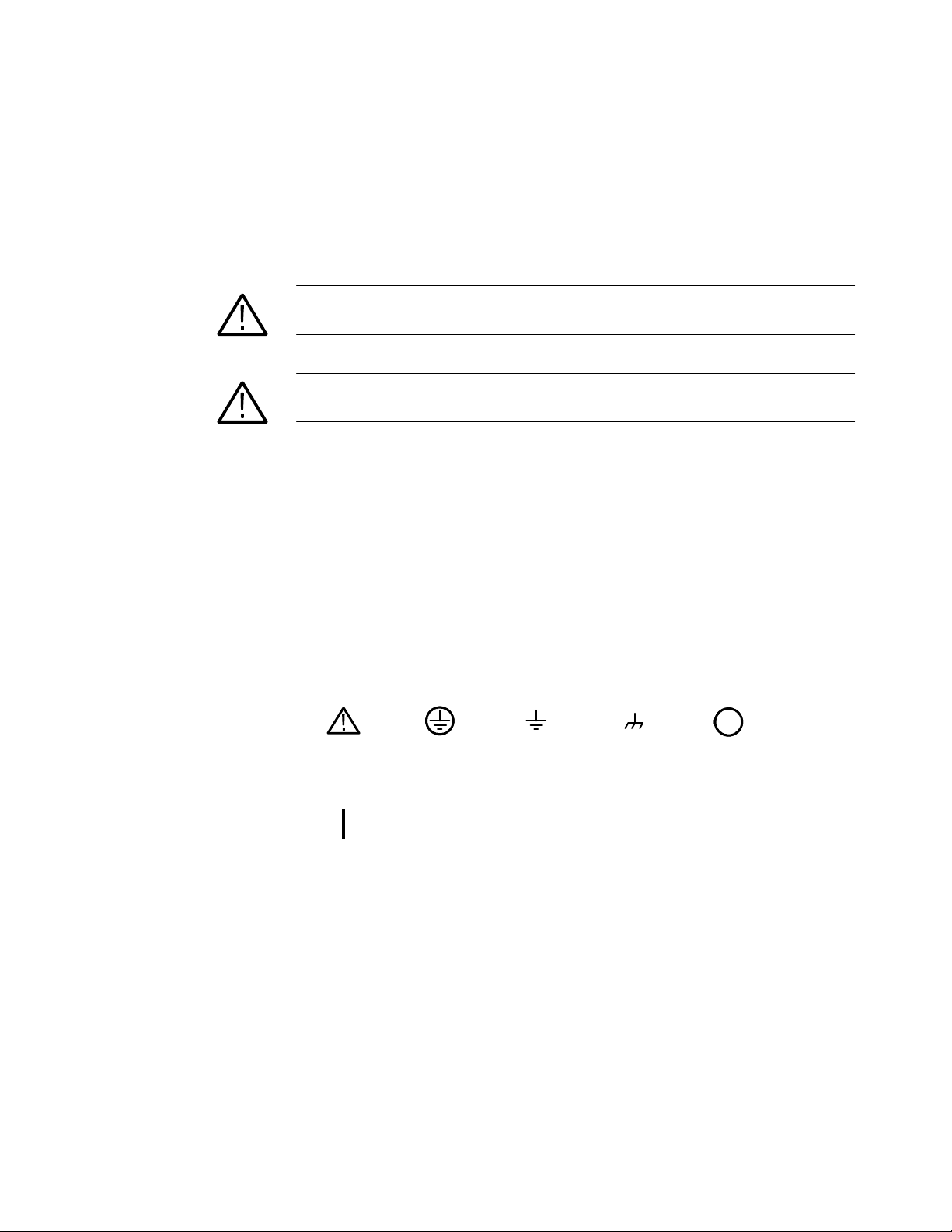
The following symbols may appear on the product:
CAUTION
Refer to Manual
Mains Connected
ON (Power)
vi
Protective Ground
(Earth) Terminal
TDS1000B and TDS2000B Series Oscilloscope Service Manual
Earth Terminal
Chassis Ground
Mains Disconnected
OFF (Power)

Service Safety Summary
Only qualified personnel should perform service procedures. Read this Service
Safety Summary and the General Safety Summary before performing any service
procedures.
Do Not Service Alone. Do not perform internal service or adjustments of this
product unless another person capable of rendering first aid and resuscitation is
present.
Disconnect Power. To avoid electric shock, switch off the instrument power, then
disconnect the power cord from the mains power.
Use Care When Servicing With Power On. Dangerous voltages or currents may
exist in this product. Disconnect power, remove battery (if applicable), and
disconnect test leads before removing protective panels, soldering, or replacing
components.
To avoid electric shock, do not touch exposed connections.
TDS1000B and TDS2000B Series Oscilloscope Service Manual
vii

Service Safety Summary
viii
TDS1000B and TDS2000B Series Oscilloscope Service Manual

Preface
Manual Conventions
This service manual provides information to verify performance of, calibrate,
troubleshoot, disassemble, and replace parts on the TDS1000B and TDS2000B
Series Digital Storage Oscilloscopes.
Unless noted otherwise, the term “oscilloscope” refers to all models in the
TDS1000B and TDS2000B series.
This manual uses certain conventions that you should become familiar with
before attempting service.
Modules
Replaceable Parts
Safety
Related Documentation
Throughout this manual, any replaceable component, assembly, or part is
referred to by the term module. A module is composed of electrical and
mechanical assemblies, circuit cards, interconnecting cables, and user-accessible
controls.
This manual refers to any field-replaceable assembly or mechanical part
specifically by its name or generically as a replaceable part. In general, a
replaceable part is any circuit board or assembly, such as the hard disk drive, or a
mechanical part, such as the I/O port connectors, that is listed in the replaceable
parts list.
Symbols and terms related to safety appear in the Service Safety Summary found
at the beginning of this manual.
To read about Use these documents
Installation and Operation TDS1000B and TDS2000B Series Digital Storage
Oscilloscopes User Manual (available in 11 languages)
Programmer Commands TDS200, TDS1000/2000, TDS1000B/2000B, and TPS2000
Series Digital Oscilloscopes Programmer Manual
Analysis and Connectivity Tools Getting Started with OpenChoicet Solutions Manual
TDS1000B and TDS2000B Series Oscilloscope Service Manual
ix

Preface
x
TDS1000B and TDS2000B Series Oscilloscope Service Manual

Specifications


Specifications
g
q
These specifications apply to all TDS1000B and TDS2000B series oscilloscopes.
To verify that an oscilloscope meets specifications, it must first meet the
following conditions:
H The oscilloscope must have been operating continuously for twenty minutes
H You must perform the Do Self Cal operation, accessible through the Utility
H The oscilloscope must be within the factory calibration interval of one year.
Specifications begin in Table 1--1. All specifications are guaranteed unless noted
“typical.” Specifications that are marked with the n symbol are checked in the
chapter Performance Verification.
Table 1- 1: Oscilloscope specifications
Acquisition
within the specified operating temperature.
menu, if the operating temperature has changed by more than 5 °C(9°F)
since the last time the Do Self Cal operation was performed.
Acquisition Modes Sample, Peak Detect, and Average
Acquisition Rate,
typical
Single Sequence Acquisition Mode Acquisition Stops After
Up to 180 waveforms per second, per channel (Sample acquisition mode, no measurements)
Sample, Peak Detect Single acquisition, all channels simultaneously
Average N acquisitions, all channels simultaneously. N is selectable from 4,
16, 64, and 128
TDS1000B and TDS2000B Series Oscilloscope Service Manual
1- 1

Specifications
g
Ref
ati
t
BNC
I
fth
val
x
ceeded,d
ama
cil
losc
a
y
Table 1- 1: Oscilloscope specifications (Cont.)
Inputs
Input Coupling DC, AC, or GND
Input Impedance, DC
Coupled
P2220 Probe
Attenuation
Supported Probe
Attenuation Factors
Supported Current
Probe Scales
Maximum Voltage Overvoltage Category* Maximum Voltage
Between Signal and
erence
npu
BNC
1MΩ ±2% in parallel with 20 pF ±3pF
1X, 10X
1X, 10X, 20X, 50X, 100X, 500X, 1000X
5 V/A, 1 V/A, 500 mV/A, 200 mV/A, 100 mV/A, 20 mV/A, 10 mV/A, 1 mV/A
CAT I and CAT II 300 V
RMS
Derate at 20 dB/decade above 100 kHz to 13 V peak AC at 3 MHz
For non-sinusoidal waveforms, peak value must be less than 450 V. Excursion above 300 V should be less
than 100 ms duration and the duty factor is limited to ≤ 44%.
{
and above.
RMS signal level including any DC component removed through AC coupling must be limited to 300 V.
ese
Channel-to-Channel
Common Mode
Rejection, typical
uesare e
TDS1001B TDS1002B, TDS2002B,
TDS2004B
100:1 at 60 Hz
20:1at20MHz
{
100:1 at 60 Hz
20:1at30MHz
ge to theos
{
ope m
result.
TDS1012B, TDS2012B, TDS2014B, TDS2022B,
TDS2024B
100:1 at 60 Hz
10:1at50MHz
{
Measured on MATH Ch1 -- Ch2 waveform, with test signal applied between signal and common of both
channels, and with the same VOLTS/DIV and coupling settings on each channel
Measured on MATH Ch3 -- Ch4 waveform for 4-channel models
Channel-to-Channel
Crosstalk
TDS1001B TDS1002B, TDS2002B,
TDS2004B
≥ 100:1 at 20 MHz{≥ 100:1 at 30 MHz
{
TDS1012B, TDS2012B,
TDS2014B
≥ 100:1 at 50 MHz
{
TDS2022B, TDS2024B
≥ 100:1 at 100 MHz
Measured on one channel, with test signal applied between signal and common of the other channel, and
with the same VOLTS/DIV and coupling settings on each channel
*
Refer to the Overvoltage Category description in the TDS1000B and TDS2000b User manual, available on the Tektronix Web site
at www.tektronix.com/manuals.
{
Bandwidth reduced to 6 MHz with a 1X probe.
{
1- 2
TDS1000B and TDS2000B Series Oscilloscope Service Manual

Specifications
n
VerticalPositio
n
inSampleandAverag
e
typical
y
p
Table 1- 1: Oscilloscope specifications (Cont.)
Verticalw
Digitizers 8-bit resolution (except when set to 2 mV/div), each channel sampled simultaneously
VOLTS/DIV Range 2 mV/div to 5 V/div at input BNC
Position Range, typical 2 mV/div to 200 mV/div, ±2V
> 200 mV/div to 5 V/div, ±50 V
n Vertical Position
Accuracy
n Analog Bandwidth
in Sample and Average
modes at BNC or with
P2220 probe set to 10X,
DC Coupled
Analog Bandwidth in
Peak Detect mode
(50 s/div to 5 s/div}),
Selectable Analog Bandwidth Limit, typical
Lower Frequency
Limit, AC Coupled
Rise Time at BNC,
typical
Peak Detect Response}Captures 50% or greater amplitude of pulses ≥12 ns wi de typical (50 s/div to 5 s/div) in the center 8
Measurement Type Volts/Div Setting Position Accuracy
Accuracy of the nominal voltage level
represented by the code at the center of
the dynamic range of the A/D converter
TDS1001B TDS1002B, TDS2002B,
TDS2004B
40 MHz*{
20 MHz* (when vertical scale is set to < 5 mV)
TDS1001B TDS1002B, TDS2002B,
30 MHz*{ 50 MHz*{ 75 MHz*{
20 MHz* (when vertical scale is set to < 5 mV)
20 MHz*
≤ 10 Hz at BNC
≤ 1 Hz when using a 10X passive probe
TDS1001B TDS1002B, TDS2002B,
< 8.4ns <5.8ns <3.5ns <2.1ns
vertical divisions
60 MHz*{ 100 MHz*{ 200 MHz*{
TDS2004B
TDS2004B
2 mV/div to 200 mV/div ±(1% X selected value + 0.1 div + 5 mV)
within the range ±1.8 V
> 200 mV/div to 5 V/div ±(1% X selected value + 0.1 div + 125
mV) within the range ±45 V
TDS1012B, TDS2012B,
TDS2014B
TDS1012B, TDS2012B, TDS2014B, TDS2022B, TDS2024B
TDS1012B, TDS2012B,
TDS2014B
W
W
TDS2022B, TDS2024B
0 °Cto+35°C(32°Fto95°F)
160 MHz*{
0 °Cto+50°C(32°F to 122 °F)
TDS2022B, TDS2024B
For TDS1001B, the pulse must be at least 13 ns wide
w Specifications are with the Probe " Voltage " Attenuation option set to 1X.
W
The “selected value” is the offset value indicated by the oscilloscope in the hint line (not the measurement).
* Bandwidth reduced to 6 MHz with a 1X probe and the Bandwidth Limit is turned off.
{ When vertical scale is set to ≥ 5mV.
}
The oscilloscope reverts to Sample mode when the SEC/DIV (horizontal scale) is set from 2.5 s/div to 5 ns/div on 1 GS/s
models, or from 2.5 s/div to 2.5 ns/div on 2 GS/s models. The Sample mode can still capture 10 ns glitches.
TDS1000B and TDS2000B Series Oscilloscope Service Manual
1- 3

Specifications
n
DCGainAccurac
y
idth)
g
Table 1- 1: Oscilloscope specifications (Cont.)
Verticalw
n DC Gain Accuracy
Volts Measurement
Repeatability, Average
Acquisition Mode
DC Measurement Measurement Type Accuracy
Accuracy, Average
Acquisition Mode
Horizontal
Sample Rate Range TDS1001B, TDS1002B, TDS2004B,
Waveform Interpolation (sin x)/x
Record Length 2500 samples for each channel
SEC/DIV Range TDS1001B, TDS1002B, TDS2004B,
n Sample Rate and
Delay Time Accuracy
Delta Time Measurement Conditions Accuracy
Accuracy (Full Bandw
Position Range TDS1001B, TDS1002B, TDS2004B, TDS1012B, TDS2002B, TDS2012B, TDS2014, TDS2022B, TDS2024B
w Specifications are with the Probe " Voltage " Attenuation option set to 1X.
±3% for Sample or Average acquisition mode, 5 V/div to 10 mV/div
±4% for Sample or Average acquisition mode, 5 mV/div and 2 mV/div
Delta volts between any two averages of
≥ 16 waveforms acquired under same setup
and ambient conditions
Average of ≥ 16 waveforms with vertical
position at zero
Average of ≥ 16 waveforms with vertical scale
with Vertical Scale 2 mV/div to 200 mV/div and
-1.8 V < Vertical Position < 1.8V
Average of ≥ 16 waveforms with vertical
position with Vertical Scale > 200 mV/div and
-45 V < Vertical Position < 45 V
TDS1012B, TDS2002B, TDS2012B, TDS2014B
5S/sto1GS/s 5S/sto2GS/s
TDS1012B, TDS2002B, TDS2012B, TDS2014B
5 ns/div to 50 s/div, in a 1, 2.5, 5 sequence 2.5 ns/div to 50 s/div, in a 1, 2.5, 5 sequence
±50 parts per million (ppm) over any ≥1 ms time interval
Single-shot, Sample mode ±(1 sample interval + 100 ppm × reading + 0.6 ns)
> 16 averages ±(1 sample interval + 100 ppm × reading + 0.4 ns)
Sample interval = s/div ÷ 250
5ns/divto10ns/div (--4 div × s/div) to 20 ms
25 ns/div to 100 s/div (--4 div × s/div) to 50 ms
250 s/divto10s/div (--4 div × s/div) to 50 s
25 s/div to 50 s/div (--4 div × s/div) to 250 s
TDS2022B, TDS2024B
2.5 ns/div (--4 div × s/div) to 20 ms
±(3% × reading + 0.05 div)
±(3% × reading + 0.1 div + 1 mV) when 10 mV/div or
greater is selected
±[3% × (reading + vertical position) + 1% of vertical
position + 0.2 div + 7 mV]
±[3% × (reading + vertical position) + 1% of vertical
position + 0.2 div +175 mV]
TDS2022B, TDS2024B
TDS2022B, TDS2024B
1- 4
TDS1000B and TDS2000B Series Oscilloscope Service Manual

Table 1- 1: Oscilloscope specifications
p
y
qy,typic
a
ggy
,
tDC
C
l
i
typical
Trigger
Specifications
n Trigger Sensitiv-
ity, Edge Trigger
Type, DC coupling,
with a stable display
of a trigger event
Trigger Sensitivity,
Edge Trigger Type,
DC Coupling,
Frequency Counter,
l
Coupling Sensitivity TDS1001B, TDS1002B,
TDS1012B, TDS2002B,
TDS2004B, TDS2012B,
TDS2014B
DC EXT 200 mV from DC to 100 MHz* 200 mV from DC to 100 MHz*
EXT/5 1 V from DC to 100 MHz* 1 V from DC to 100 MHz*
CH1, CH2,
CH3, CH4
≥5mV/div
CH1, CH2,
CH3, CH4
2mV/div
Coupling Sensitivity TDS1001B, TDS1002B,
DC
EXT 300 mV from DC to 100 MHz* 300 mV from DC to 100 MHz*
1 div from DC to 10 MHz*
1.5 div from 10 MHz to Full
2.5 div from DC to 10 MHz*
4divfrom10MHzto20MHz
TDS1012B, TDS2002B,
TDS2004B, TDS2012B,
TDS2014B
TDS2022B, TDS2024B
350 mV from 100 MHz to 200 MHz*
1.75 V from 100 MHz to 200 MHz*
1 div from DC to 10 MHz*
1.5 div from 10 MHz to 100 MHz
2 div from 100 MHz to Full
TDS2022B, TDS2024B
EXT/5 1.5 V from DC to 100 MHz* 1.5 V from DC to 100 MHz*
CH1, CH2,
CH3, CH4
≥5mV/div
CH1, CH2,
CH3, CH4
2mV/div
Trigger Sensitivity, Coupling Sensitivity
Edge Trigger Type,
no
typical
* Bandwidth reduced to 6 MHz with a 1X probe.
oup
ng,
AC Same as DC at 50 Hz and above
NOISE REJ Reduces the DC-coupled trigger sensitivity by 2 times for > 10 mV/div to 5 V/div
HF REJ Same as the DC-coupled limit from DC to 7 kHz, attenuates signals above 80 kHz
LF REJ Same as the DC-coupled limits for frequencies above 300 kHz, attenuates signals
below 300 kHz
500 mV from 100 MHz to 200 MHz*
3 V from 100 MHz to 200 MHz*
1.5 div from DC to 10 MHz*
3 div from 10 MHz to Full
4 div from DC to 10 MHz*
7.5 div from 10 MHz to 20 MHz
TDS1000B and TDS2000B Series Oscilloscope Service Manual
1- 5

Specifications
ggg
,
g
g
y,g
Table 1- 1: Oscilloscope specifications (Cont.)
Trigger
Trigger Level Range, Source Range
typical
Trigger Level Accura- Accuracies are for signals having rise and fall times ≥ 20 ns
cy, typical
SET LEVEL TO 50%,
typical
Default Settings,
Video Trigger
Sensitivity, Video Trig- Composite video signal
ger Type, typical
Signal Formats and
Field Rates, Video
Trigger Type
CH1, CH2, CH3, CH4 ±8 divisions from center of screen
EXT ±1.6 V
EXT/5 ±8V
AC Line Can not be set
Source
Internal
EXT ±(6% of setting + 40 mV) for signals within ±800 mV
EXT/5 ±(6% of setting + 200 mV) for signals within ±4V
Operates with input signals ≥ 50 Hz
Coupling is AC and Auto mode except for a single sequence acquisition
Source Range
Internal Peak-to-peak amplitude of 2 divisions
EXT 400 mV
EXT/5 2V
Supports NTSC, PAL, and SECAM broadcast systems for any field or any line
Accuracy
±0.2 div × volts/div within ±4 divisions from center screen
Holdoff Range 500 ns to 10 s
Pulse Width trigger
Pulse Width
Trigger modes
Pulse Width
Trigger Point
1- 6
Trigger when < (Less than), > (Greater than), = (Equal), or ≠ (Not Equal);
Positive pulse or Negative pulse
Equal: The oscilloscope triggers when the trailing edge of the pulse crosses the trigger level.
Not Equal: If the pulse is narrower than the specified width, the trigger point is the trailing edge. Otherwise, the
oscilloscope triggers when a pulse continues longer than the time specified as the Pulse Width.
Less than: The trigger point is the trailing edge.
Greater than (also called time-out trigger): The oscilloscope triggers when a pulse continues longer than the
time specified as the Pulse Width.
TDS1000B and TDS2000B Series Oscilloscope Service Manual

Table 1- 1: Oscilloscope specifications (Cont.)
Pulse Width trigger
Pulse Width Range Selectablefrom33nsto10s
Pulse Width
Resolution
Equal Guardband t > 330 ns: ±5% ≤ guardband < ±(5.1% + 16.5 ns)
Not Equal Guardband t > 330 ns: ±5% ≤ guardband < ±(5.1% + 16.5 ns)
Trigger frequency counter
Readout Resolution 6 digits
Accuracy (typical) ±51 parts per million including all frequency reference errors and ±1 count errors
Frequency Range AC coupled, 10 Hz minimum to rated bandwidth
Signal Source Pulse Width or Edge Trigger modes: all available trigger sources
16.5 ns or 1 part per thousand, whichever is larger
t ≤ 330 ns: guardband = ±16.5 ns
165 ns < t ≤ 330 ns: guardband = --16.5 ns/+33 ns
t ≤ 165 ns: guardband = ±16.5 ns
Specifications
The Frequency Counter measures trigger source at all times in Pulse Width or Edge modes, including when
the oscilloscope acquisition is halted due to changes in the run status, or acquisition of a single shot event has
completed.
Pulse Width Trigger mode: The oscilloscope counts pulses of significant magnitude inside the 250 ms
measurement window that qualify as triggerable events, such as narrow pulses in a PWM pulse train if
set to < mode and the width is set to a relatively small time.
Edge Trigger mode: The oscilloscope counts all edges of sufficient magnitude and correct pol ari ty.
Video Trigger mode: The Frequency Counter does not operate.
Measurements
Cursors Amplitude difference between cursors (ΔV, ΔA, ΔVA)
Time difference between cursors (Δt)
Reciprocal of ΔtinHertz(1/Δt)
Automatic Measurements
Frequency, Period, Mean, Pk-Pk, Cycle RMS, Min, Max, Rise Time, Fall Time, Pos Width, N eg Width
TDS1000B and TDS2000B Series Oscilloscope Service Manual
1- 7

Specifications
gy,yp
p
Table 1- 2:
Oscilloscope general specifications
Display
Display Type 145 mm (5.7 in) diagonal liquid crystal
Display Resolution 320 horizontal by 240 vertical pixels
Display Contrast* Adjustable, temperature compensated
Backlight Intensity, typical Monochrome display Color display
75 cd/m
2
65 cd/m
2
Probe compensator output
Output Voltage, typical 5Vinto≥ 1MΩ load
Frequency, typical 1 kHz
Power Source
Source Voltage
100 -- 240 VAC
115 VA C
RMS
( 10%) 50/60 Hz ( 10%)
RMS
( 10%) 400 Hz ( 10%)
Power Consumption Less than 30 W
Fuse 1 A, T rating, 250 V
Environmental
Pollution Degree Pollution degree 2{, for indoor use only. Do not operate in an environment where conductive pollutants
may be present.
Temperature Operating 0 °Cto+50°C(32°F to 122 °F)
Non-Operating -- 4 0 °Cto+71°C(--40°F to 159.8 °F)
Cooling Method Convection
Humidity +40 °C or below
5% to 85% relative humidity
(+104 °F or below)
+41 °Cto+50°C
5% to 45% relative humidity
(106 °F to 122 °F)
>+50 °Cto+71°C
Wet bulb temperature of < 37 °C, which is 12% at +71 °C
(>122 °F to 160 °F)
Altitude 3,000 m (approximately 10,000 ft.)
Random Vibration Operating 0.31 g
Non-Operating 2.46 g
from 5 Hz to 500 Hz, 10 minutes on each axis
RMS
from 5 Hz to 500 Hz, 10 minutes on each axis
RMS
Mechanical Shock Operating 50 g, 11 ms, half sine
1- 8
TDS1000B and TDS2000B Series Oscilloscope Service Manual

Specifications
Table 1- 2:
Mechanical
Size Height 158 mm (6.220 in)
Weight (approximate) Instrument only 2.0 kg (4.375 lbs)
* Adjustable through the Display menu.
{ As defined in IEC 61010--1:2001.
Oscilloscope general specifications (Cont.)
Width 326.3 mm (12.845 in)
Depth 124.1 mm (4.885 in)
TDS1000B and TDS2000B Series Oscilloscope Service Manual
1- 9

Specifications
1- 10
TDS1000B and TDS2000B Series Oscilloscope Service Manual

Operating Information


Operating Information
For information on installing and operating your TDS1000B and TDS2000B
Series Digital Storage Oscilloscope, refer to the TDS1000B and TDS2000B
Series Digital Storage Oscilloscope User Manual. The user manuals are
available in eleven languages and are on the Web at www.tektronix.com.
TDS1000B and TDS2000B Series Oscilloscope Service Manual
2- 1

Operating Information
2- 2
TDS1000B and TDS2000B Series Oscilloscope Service Manual
 Loading...