

Tekmar tekmarNet 4 544, tN4 544, tekmarNet 4 543, tN4 543 Wiring Brochure
- Wiring Brochure
tekmarNet®4 Thermostat 544
W 544
12/08
1
Information
Brochure
Choose controls
to match
application
2
Application
Brochure
Design your
mechanical
applications
3
Brochure
Rough-in
instructions
Layout
wiring
4
Wiring
Brochure
Wiring and
installation of
specific control
5
Data
Brochure
Control settings
and sequence of
operation
6
Job
Record
Record settings &
wiring details for
future reference
Overview
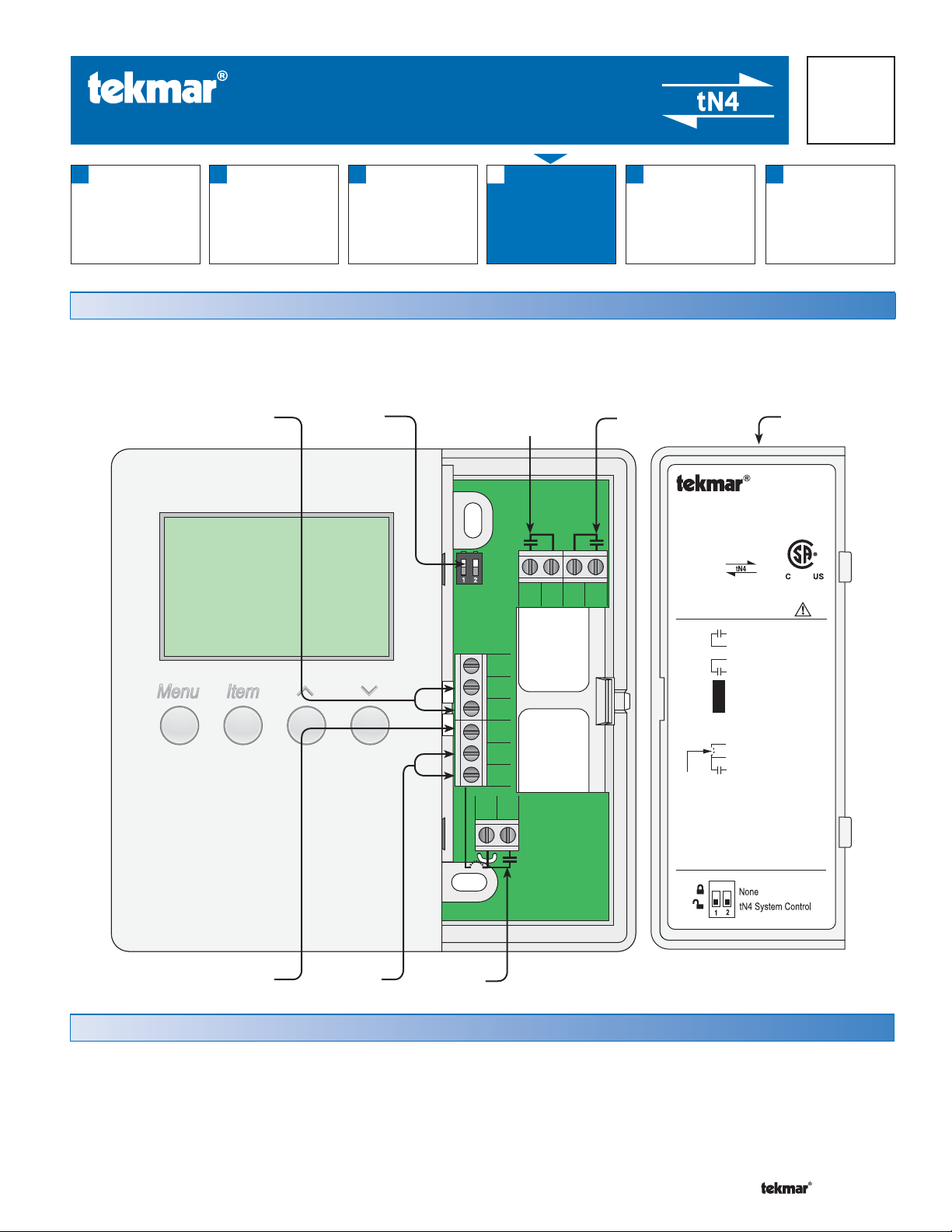
The following brochure describes how to wire the tekmar tekmarNet®4 (tN4) thermostat 544. The 544 has outputs for:
one heat stage, one cooling stage and one fan. The 544 has inputs for two auxiliary sensors. The wiring of 544 thermostat
is simple and cost effective.
Auxiliary
Sensors
DIP
Switches
Com
Rh1
1st Stage
Cooling
Y1 Rc G1 G1
S2
S1
tN4
C
R
W1
1st Stage
Fan
Wiring
Cover
tNt 544
One Stage Heat, One Stage Cool, One Fan
Power: 24 V (ac) ±10% 60 Hz 1.5 VA
Relays: 24 V (ac) 2 A
992-03
Meets Class B: Canadian ICES, FCC Part 15
Terminal Functions
G1
Fan 1 Relay
G1
Fan 1 Relay
Rc
Power Cooling
Y1
Cool 1 Relay
Com
Sensor Common
S2
Sensor 2
No Power
S1
Sensor 1
®
tekmarNet 4
Power Neutral
Power 24 V (ac)
Heat 1 Relay
Heat 1 Relay
To isolate
relay, cut
jumper
tN4
C
R
Rh1
W1
DIP Switch Functions
tN4
Network
24 V (ac)
Power
1st Stage
Heating
Table of Contents:
Definitions ....................................................................... 2
Rough-In Wiring .............................................................2
Remove the Wiring Cover ..............................................3
Mounting the Thermostat ...............................................3
Wiring Symbols ...............................................................3
1 of 12 © 2008 W 544 - 12/08
Electrical Drawings ......................................................3-7
Wiring the Thermostat .................................................8-9
Troubleshooting the Wiring ........................................... 10
Testing the Wiring ......................................................... 11
Technical Data .............................................................. 12
Defi nitions
•
•
•
•
•
•
•
The following defined terms and symbols are used throughout this manual to bring attention to the presence of hazards of
various risk levels, or to important information concerning the life of the product.
– Caution: Refer to accompanying documents.
– Caution: Refer to accompanying documents.
INSTALLATION
CATEGORY II
– Local level appliances.
Caution
Improper installation and operation of this control could result
in damage to the equipment and possibly even personal
injury or death. It is your responsibility to ensure that this
control is safely installed according to all applicable codes
and standards. This electronic control is not intended for
uses as a primary limit control. Other controls that are
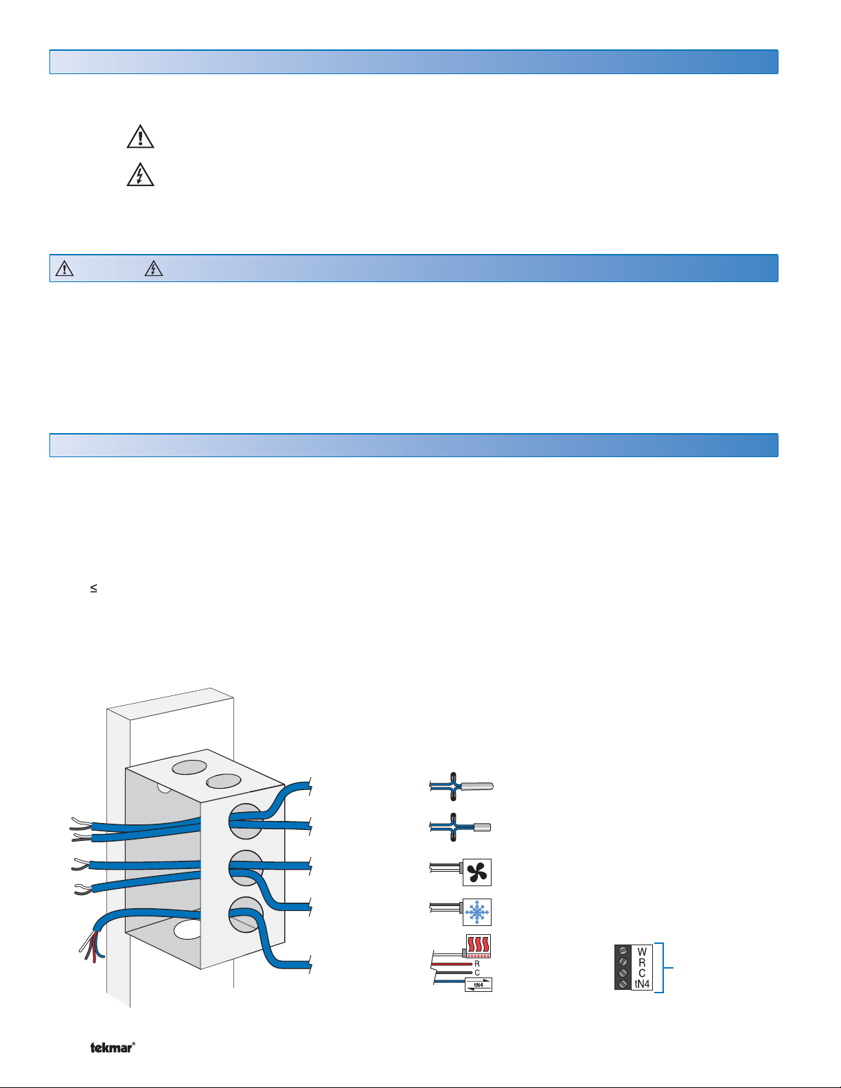
Rough-In Wiring
Choose the placement of the thermostats early in the
construction process to enable proper wiring during
rough-in.
Consider the following:
Interior Wall
Keep dry. Avoid potential leakage onto the control.
RH 80% to 88°F (31°C), down to 50% from 104 to
122°F (40 to 50°C). Non-condensing environment.
No exposure to extreme temperatures beyond 32 - 122°F
(0 - 50°C)
No draft, direct sun, or other cause for inaccurate
temperature readings.
intended and certified as safety limits must be placed into
the control circuit. Do not attempt to service the control.
Refer to qualified personnel for servicing. Apart from any
field replaceable fuse(s) there are no user serviceable
parts. Attempting to do so voids warranty and could result
in damage to the equipment and possibly even personal
injury or death.
Away from equipment, appliances, or other sources of
electrical interference.
Easy access for wiring, viewing, and adjusting the display
screen.
Approximately 5 ft. (1.5 m) off the finished floor.
Use standard 18 AWG wire for the thermostat power, stages
tN4 and sensor connections.
Refer to the diagram below to determine the number of
conductors to run from each piece of equipment to the
thermostat location.
2 Cond. / 18 AWG
2 Cond. / 18 AWG
2 Cond. / 18 AWG
2 Cond. / 18 AWG
4 Cond. / 18 AWG
© 2008 W 544 - 12/08 2 of 12
Sensor 2
Sensor 1
Fan 1
1st Stage Cool
1st Stage Heat
24 V (ac) Power
tN4 Network
Note: When multiple wires
run to the same equipment
location, wiring conductors
can share one wire jacket.
Zone Manager
•
•
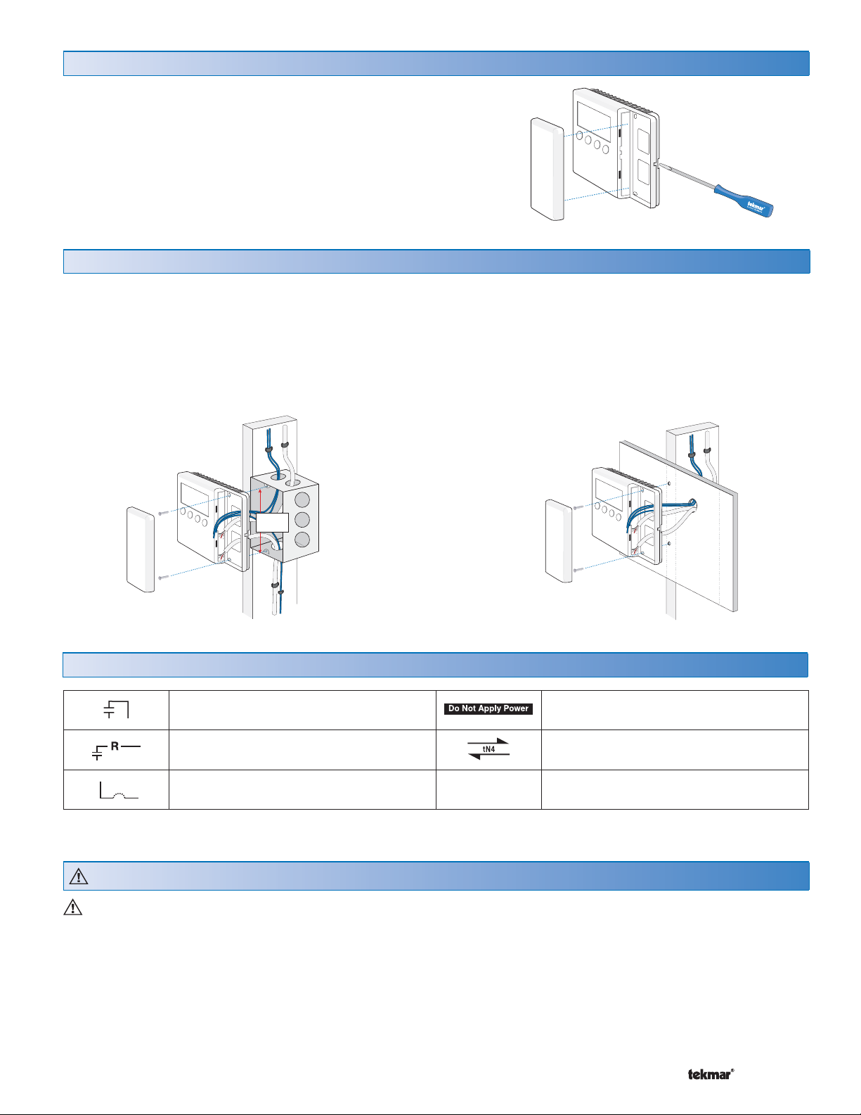
Remove the Wiring Cover:
•
•
•
•
To remove the wiring cover:
Place a small slot screwdriver or similar tool into the slot
located on the right side of the thermostat.
While pushing against the plastic tab, lift off the wiring
cover.
Mounting the Thermostat
If a single or double gang switch box is used, mount the
thermostat directly to the box.
Feed the wiring through the openings in the back of the
thermostat.
Use the upper and lower screw holes to fasten the
thermostat to the box.
Stud
Switch Box
3 1/4”
Terminal
Cover
Thermostat
Base
(83 mm)
Wiring Symbols
If a switch box was not used, mount the thermostat directly
to the wall.
Feed the wiring through the openings in the back of the
thermostat.
Use screws in the upper and lower screw holes to fasten
the thermostat to the wall. At least one of the screws
should enter a wall stud or similar rigid material.
Stud
Wall
OR
Thermostat
Terminal
Cover
Base
Dry contact switch. Operates a device.
Powered switch. 24 V (ac), switched
output to valve, pump relay etc.
Do not apply power to these terminals.
Serious control damage will result.
tekmarNet®4
Factory jumper.
Electrical Drawings
The electrical drawing examples on the following
pages show the 544 in common applications. Choose
the drawing that most accurately depicts the components
in your system and use that drawing as a guide to aid in
wiring your system.
These are only concept drawings, not engineered drawings.
They are not intended to describe a complete system nor
any particular system. It is up to the system designer to
3 of 12 © 2008 W 544 - 12/08
determine the necessary components for and configuration
of the particular system being designed including additional
equipment isolation relays (for loads greater than the
controls specified output ratings) and any safety devices
which in the judgement of the designer are appropriate in
order to properly size, configure and design that system
and to ensure compliance with building and safety code
requirements.
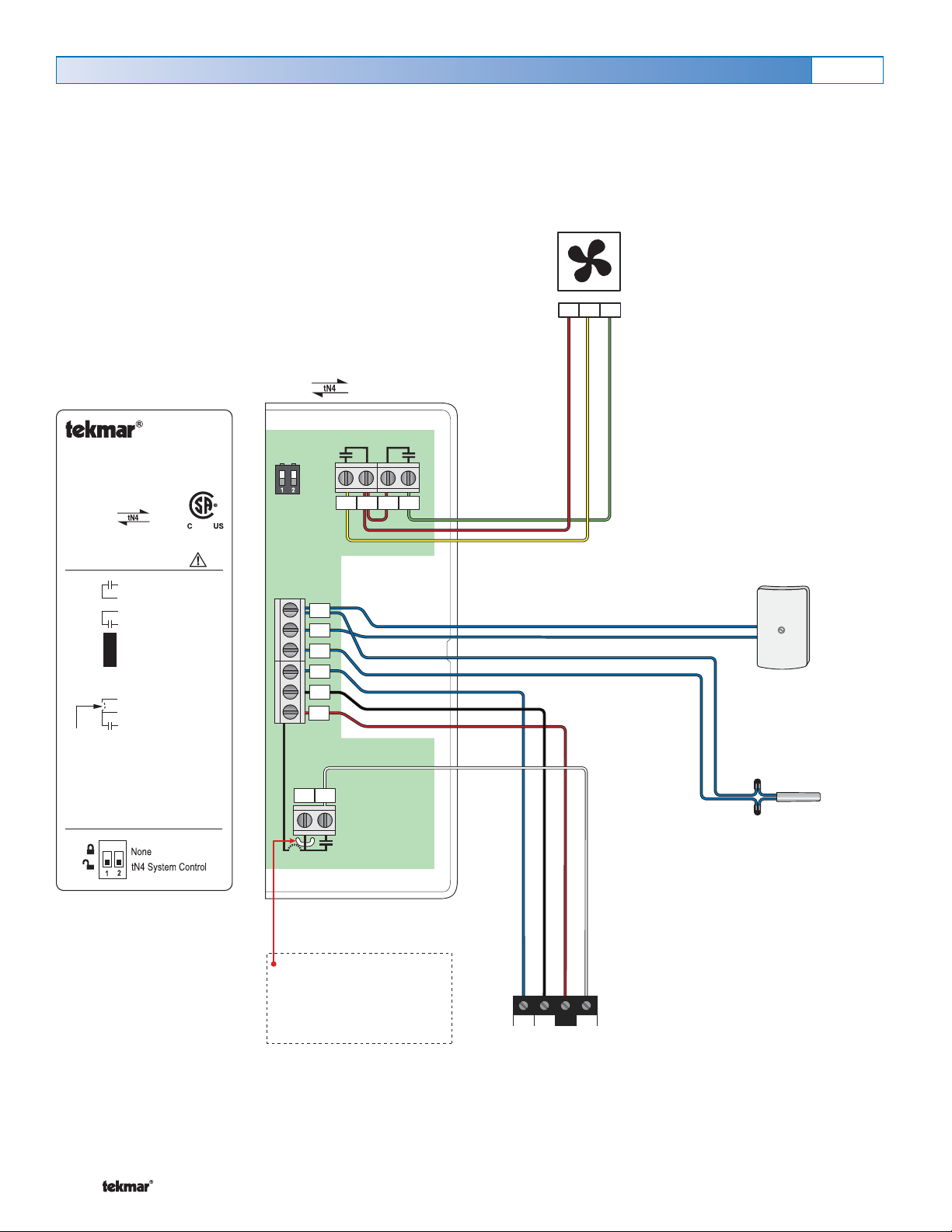
Electrical Application 544 E1
Description:
One Stage Heating (H1 = Radiant), One Stage Cooling (C1 = Compressor), One Speed Fan (F1 = C1), Fan Mode = 1.
Legend:
Sensor 1 = Floor
Sensor 2 = Outdoor
Cooling Equipment
1 Stage Cooling
1 Stage Fan
RcY1G1
544 tNt
tNt 544
One Stage Heat, One Stage Cool, One Fan
Power: 24 V (ac) ±10% 60 Hz 1.5 VA
Relays: 24 V (ac) 2 A
992-03
Meets Class B: Canadian ICES, FCC Part 15
Terminal Functions
G1
Fan 1 Relay
G1
Fan 1 Relay
Rc
Power Cooling
Y1
Cool 1 Relay
Com
Sensor Common
S2
Sensor 2
No Power
S1
Sensor 1
®
tekmarNet 4
Power Neutral
Power 24 V (ac)
Heat 1 Relay
Heat 1 Relay
To isolate
relay, cut
jumper
tN4
C
R
Rh1
W1
DIP Switch Functions
4321
Y1
Rc
G1
G1
Outdoor Sensor
070
5
6
7
8
9
10
Com
S2
S1
tN4
C
R
Slab Sensor
079
Rh1
W1
1211
Factory installed jumper
connects R to Rh1
(terminals 11 to 12) To
isolate Rh1-W1 relay,
cut jumper
© 2008 W 544 - 12/08 4 of 12
tN4 C R W
Zone Manager
 Loading...