


INSTRUCTION MANUAL UK (pag. 2)
NOTICE D’ UTILISATION FR
TM95C61X 40297203
TM95C31X 40297202
(pag. 15)
COD. 310610

PLEASE READ THE INSTRUCTIONS BOOKLET BEFORE INSTALLING AND USING THE APPLIANCE.
These instructions are only for those countries whose symbols appear on the front of the booklet
and on the serial no. plate of the appliance.
The manufacturer may not be held liable for any damage to objects or people, resulting from the
improper or erroneous installation of the appliance.
The manufacturer is not responsible for any inaccuracies, due to printing or typing errors, in this booklet.
The drawings (in the figures) are indicative only.
The manufacturer may make product modifications when considered necessary and useful, without this
changing essential safety and operating characteristics.
HEIGHT-ADJUSTABLE FEET (figure) 1)
The feet are packed in the top box.
The feet should be installed with the cooker close to its final installation position; the feet are not safe to
move the cooker long distances.
After unpacking the cooker, lift it with your foot, to fit the cooker feet in the bases at the bottom. Slowly lower
the cooker so its weight is resting on the feet and on the assembly fixings. We recommend using a lifting
device or pallet instead of tilting the cooker.
INSTALLING THE TOEKICK PANEL (only available for some models)
After installing the feet, install the cooker skirt as shown in the pictures in Figure 2. 2
INSTALLING THE (UPSTAND) RISER
Remove the 2 screws securing the hob at the rear, as shown in (figure 3)
Put the upstand in place and secure at the bottom with the two screws, as shown in (figure 3)
Secure the middle of the upstand using the screws provided with the upstand (figure 3)
INSTALLING THE HOB RAIL AND OVEN HANDLE
The rail and handle are packed with the upstand.
The rail is only available on some models.
Assemble the hob rail and oven handle as shown in the pictures (figures 4A – 4B)
Before connecting the appliance to the gas mains, make sure the data on the rating plate affixed inside the
warming drawer or at the rear of the oven correspond to those of the gas mains.
A label on the last page of this booklet and inside the warming drawer (or at the rear) of the appliance
gives information for adjusting the appliance: type of gas and operating pressure.
IMPORTANT: this appliance must be installed in compliance with current national standards in force and
used only in a well-ventilated room.
NOTE: The gas union of the appliance has a ½ cylindrical male gas thread, conforming to UNI-ISO 228-1
standards.
To connect the appliance to the gas mains using a flexible rubber pipe, an additional rubber union is
required (Figure 6 ) supplied with the appliance, conforming to the UNI 7141 standard.
CONNECTING THE APPLIANCE TO THE GAS MAINS
ADJUSTMENT FOR DIFFERENT TYPES OF GAS
BEFORE CARRYING OUT ANY MAINTENANCE, UNPLUG THE APPLIANCE FROM THE GAS AND
ELECTRICITY MAINS
REPLACING NOZZLES FOR OPERATION WITH ANOTHER TYPE OF GAS:
To change the hob burner nozzles, proceed as follows:
1. Unplug the appliance from the mains, to avoid all electrical contact.
2. Remove the pan supports from the hob (Figure 7).
3.
Remove the burner heads (Figure 7).
4. Use a 7 mm tubular hex wrench to loosen the nozzles and replace them with those suitable for the new type of
gas (Figure 8) as indicated in table no. 1.
To change the oven burner nozzle proceed as follows:
1. Remove the hob by removing screws G (Figure 9) and then the hob.
2. Loosen screw V and remove the burner from its housing, taking care to avoid damaging the spark ignition and
thermocouple (Figure 10).
3. Use a 7 mm tubular hex wrench to replace nozzle R with a nozzle suitable for the new type of gas as indicated
in table no. 1.
2

To change the grill burner nozzle proceed as follows:
1. Loosen the grill screw and remove the burner from its housing, taking care to avoid damaging the spark ignition
and thermocouple (Figure 11).
Use a 7m tubular hex wrench to replace nozzle R with a nozzle suitable for the new type of gas as indicated in
2.
table no. 1.
NOTE: After replacing the nozzles, the installer shall adjust the burners as described below, seal any
regulation and pre-regulation devices, and affix the new gas regulation label, to replace the existing one.
This new label is in the bag with the spare nozzles.
TABLE NO. 1
Burner Gas type Pressur
e
mbar 1/100 mm g/h l/h kw kcal/h
Natural Gas G20 20 72 - 95 1 860
Auxiliary Butane G30 30 50 73 - 1 860
Propane G31 37 50 71 - 1 860
Natural Gas G20 20 97 - 167 1,75 1505
Semirapid Butane G30 30 65 127 - 1,75 1505
Propane G31 37 65 125 - 1,75 1505
Natural Gas G20 20 115 - 286 3 2580
Rapid Butane G30 30 85 218 - 3 2580
Propane G31 37 85 214 - 3 2580
Natural Gas G20 20 120 - 276 2,9 2494
Fish burner Butane G30 30 85 211 - 2,9 2494
Propane G31 37 85 207 - 2,9 2494
Ultra Natural Gas G20 20 131 - 334 3,5 3010
Rapid Butane G30 30 95 254 - 3,5 3010
Propane G31 37 95 250 - 3,5 3010
(model with gas oven and gas grill with double controls)
Natural Gas G20 20 135 - 352 3,7 3182
Oven Butane G30 30 90 269 - 3,7 3182
Propane G31 37 90 264 - 3,7 3182
Natural Gas G20 20 115 - 191 2 1720
Grill Butane G30 30 68 145 - 2 1720
Propane G31 37 68 143 - 2 1720
Nozzle
diameter
Nominal flow rate
(model with gas oven and gas grill with single control, or gas oven and electric grill)
Natural Gas G20 20 150 - 429 4,5 3870
Oven Butane G30 30 90 327 - 4,5 3870
Propane G31 37 90 321 - 4,5 3870
Natural Gas G20 20 115 - 191 2 1720
Grill Butane G30 30 68 145 - 2 1720
Propane G31 37 68 143 - 2 1720
ADJUSTING THE BURNERS
Adjusting the ”MINIMUM” of the burners:
Hob burner adjustment: follow the instructions below to adjust the minimum of the hob burners:
1. Light the burner setting the knob to the MINIMUM position (small flame).
2. Turn the knob of the tap, secured by simple pressure on the rod.
3. If the cooker does not have safety valves on the hob burners, insert a small slotted screwdriver in the hole of
the tap rod (Figure 12) and turn the choke screw to the right or left, until the burner flame is at the minimum; if
the cooker has safety valves, the choke screw is not situated on the rod hole, but on the body of the tap (Figure
13).
4. Make sure the flame does not go out, when switching quickly from the MAXIMUM to the MINIMUM position.
Oven burner adjustment: follow the instructions below to adjust the minimum of the burners:
1. Unplug the appliance before making the adjustment
2. Remove the knobs
3. Remove the control panel by removing the screws from the below the panel
4. Insert the thermostat knob
5. Light the burner setting the knob to the MAXIMUM position (manual lighting with a match)
6. Close the oven door and operate the oven for at least 10 minutes.
7. Set the knob to the MINIMUM position (120°) and then remove it.
8. Use a slotted screwdriver on the choke screw (Figure 14) and, while observing the flame at the same time
through the cooker porthole, evaluate the consistency of the flame so it remains on when switching quickly from
the MINIMUM to the MAXIMUM position.
9. Reassemble the front panel, proceeding as above in point 3, in reverse
Grill burner adjustment: follow the instructions below to adjust the minimum:
1) Light the burner setting the knob to the MAXIMUM position.
3

2) Close the oven door and operate the oven for at least 10 minutes.
3) Set the knob to the MINIMUM position (small flame) and then remove it.
4) The cooker is equipped with safety valves, use a small slotted screwdriver on the valve body (see fig. 13) and
turn the choke screw to the right or left, while observing the flame at the same time through the cooker porthole,
evaluate the consistency of the flame so it remains on when switching quickly from the MINIMUM to the MAXIMUM
position.
WARNING: The above-mentioned adjustment should be made only with natural gas burners, while for
those operating with liquid gas the screw must be locked at the end in a clockwise direction.
WARNING: For the model with single grill burner, the grill burner always operates at maximum and
therefore no minimum adjustment is required.
NOTE: The above-mentioned adjustment should be made only with natural gas burners, while for those
operating with liquid gas the screw must be locked at the end in a clockwise direction. The grill burner
always operates at maximum, therefore no minimum adjustment is required.
Connection to the electric power supply must conform to laws and regulations in force.
Before making the connection make sure:
The electric wiring and sockets are suitable for the maximum rating of the appliance (see the serial no. plate on
the lower part of the cooker body).
The socket or wiring is effectively earthed in accordance with laws and regulations in force. The manufacturer
shall not be held liable for failure to observe these provisions.
When the appliance is connected to the electric power supply by a socket:
Make sure the lead has a normalised plug suitable for the rating indicated on the serial no. plate. Connect the
wires according to the diagram in FIGURE 15, observing the following:
letter L (live) = brown wire;
letter N (neutral) = blue wire;
symbol
The lead must be positioned so no part of it exceeds a temperature of 75 K.
Do not use reductions, adaptors or shunts for the connection, as these could generate false contacts and cause
hazardous over-heating.
When the appliance in connected directly to the electric power supply:
Make sure there is a device to disconnect the appliance from the mains, with a contact opening distance
sufficient for complete disconnection in category III excess voltage conditions.
The earthing wire must not be interrupted by the switch.
Alternatively, a high-sensitivity residual current device can be used to protect the electrical connection.
We strongly recommend securing the green-yellow earthing wire to an efficient earthing system.
WARNING: If the power lead is replaced, the earthing wire (yellow-green) connected to the terminal board
should be 2 cm longer than the other wires.
CONNECTING THE APPLIANCE TO THE ELECTRIC POWER SUPPLY
(earth) = green-yellow wire;
CARING FOR YOUR APPLIANCE
NOTE: IMPORTANT INFORMATION
For cookers resting on a base
NOTE: If the appliance rests on a base, take precautions to prevent the appliance sliding off the base.
For cookers with an electric oven
The appliance heats up during use. Do not touch the heating elements inside the oven.
For cookers with an electric oven
NOTE: Accessible parts may heat up during use. Keep children away from the cooker.
For glass oven doors
Do not use abrasive cleaning products or metal spatulas with sharp edges to clean the glass oven door, as this
could scratch the surface and the glass could break.
Do not use steam cleaners to clean the appliance
NOTE: various parts of the cooker heat up reaching temperatures which seem very high but which are actually
fully within safety limits. According to these limits:
1) With the oven on at 200°C for 1 hour, front accessible parts which cannot be grasped, can reach the following
temperatures:
- Control panel: Tmax = Room Temperature +60°C
- Glass of the oven door: Tmax = Room temperature+60°C
- Metal part of the oven door: Tmax = Room temperature+45°C
2) With the oven on at 230°C for 1 hour, the parts which can be grasped, can reach the following temperatures:
- Plastic knobs: Tmax = Room temperature+60°C
- Metal oven door handle: Tmax = Room temperature+35°C
where the room temperature is the temperature in °C of the place where the appliance is installed.
4

REPLACING COMPONENTS
Before carrying out any maintenance, unplug the appliance from the gas and electricity mains.
To replace components such as knobs and burner heads, simply remove from their housing without disassembling
any part of the cooker.
To replace components such as burner holders, taps and electrical components, proceed as described in the
section on adjusting burners. If replacing the gas tap or thermostat, the two rear ramp brackets need to be
disassembled by removing the 4 screws (2 screws per bracket), which secure it to the rest of the cooker; remove
the 2 screws securing the bracket of the taps to the control panel support, after removing the knobs. If the gas or
electric thermostat is to be replaced, the rear cooker protection also needs to be removed. Remove the screws, to
take out and put back the thermostat bulb.
To replace the oven light, unscrew the light cover inside the oven (Figure 16).
NOTE: Before replacing the light, unplug the appliance from the mains.
NOTE: If replacing the power supply lead, the installer should keep the earthing wire longer than
the live wires and follow instructions for electrical connections.
USE AND MAINTENANCE MANUAL
DESCRIPTION OF HOB PARTS
Size of gas burners Table 3
BURNER SIZE (mm)
1 Auxiliary
2 Semirapid
3 Rapid
4 Triple ring
CONTROL PANEL
On the control panel, a symbol is displayed for each knob or switch, to indicate the function, as described below:
50
70
130
The symbols
show the position of the burners on the hob and the square/circle shows the burner in
question (in this case the front left burner)
The symbol
shows the oven is being used (gas oven electric grill – change-over switch with 9
settings)
the symbol
indicates the electric thermostat for electric fan ovens
the symbol shows the oven fan working button as to allow the oven to operates with fan assisted gas.
The fan operation of the oven prevents the operation of the grill, which therefore cannot be used with the fan in action.
the symbol shows the minute minder
the symbol shows the ignition key for the oven light (all except the electric fan oven)
the symbol shows the push-button for burner ignition
the symbol shows if keys are in position “on” or “off”
5

USING THE BURNERS
y
The symbols printed on the control panel above each knob indicate which knob corresponds with which burner.
The burners can be lit differently, depending on the type of appliance and its specific characteristics:
- Manual ignition (always possible even in the event of a power failure): Push down and turn the knob
corresponding to the selected burner counter clockwise, to the MAXIMUM position (large flame Figure 17) and put
a lit match to the burner.
- Electric ignition: Push down and turn the knob corresponding to the selected burner counter clockwise, to the
MAXIMUM position (large flame Figure 17), hold the knob so it is aligned with the ignition symbol (a star) and
release as soon as the burner is lit.
- Lighting burners with a safety device (thermocouple figure 18): Push down and turn the knob corresponding
to the selected burner counter clockwise, to the MAXIMUM position (large flame Figure 17), push down the knob
and use one of the above ignition methods. After ignition, hold the knob down for about 10 seconds, so the flame
can heat the thermocouple. If the burner goes out after releasing the knob, repeat the entire operation.
N.B.: Do not try to light a burner if the flame spreader is not in the right position.
Recommendations for an optimal use of the burners:
- Use suitable pans for each burner (see table no. 4 and Figure 19).
- When a pan starts to boil, turn the knob to the MINIMUM position (small flame Figure 17).
- Always use lids with pans.
TABLE NO. 4
BURNER Recommended PAN DIAMETERS (cm)
Auxiliar
12 - 14
Semirapid 14 - 26
Rapid 18 - 26
NOTE: Use flat-bottomed pans
NOTE: after cleaning the burners, make sure the caps “A” and flame spreader heads “B” are positioned
properly as shown in figure 20A and are not positioned as shown in figure 20B.
NOTE: If there is no electric power supply, the burners can be lit with matches. When cooking
foods with oil and grease, which are easily inflammable, do not leave the appliance unattended.
If the appliance is fitted with a glass lid, this may shatter when heated. Turn off all burners before lowering
the lid. Do not use sprays near the appliance when in use. When using the burners, make sure pan
handles are positioned properly. Keep children away. If the oven has a lid, clean the oven top of any food
deposits before lowering the lid.
NOTE: The use of a gas cooking appliance produces heat and humidity in the room where it is installed.
Therefore, proper aeration in the room is needed while ensuring that natural ventilation openings remain
unobstructed.
Intensive and continuous use of the appliance may require additional aeration, for example by opening a
window, or more efficient aeration by increasing the power of the mechanical exhauster, if installed.
USING THE GAS OVEN
All gas oven cookers are equipped with a safety thermostat to adjust the cooking temperature. To set the oven
temperature, turn the knob (Figure 21) counter clockwise so the indicator is aligned with the temperature selected.
The gas oven can be operated with the electric grill (figure 21).
The gas oven can also be used with the fan, operating the oven fan from the change-over switch on the control
panel. The circulation of hot air ensures that heat is evenly distributed. It is not necessary to preheat the oven,
however in the case of delicate baking, the oven should be preheated before putting in baking trays. The
convection fan cooking system changes to some extent concepts about traditional cooking. Meat does not have to
be turned during cooking and a spit does not have to be used for rotisserie roasting. The meat can be simply put
on the rack.
Cooking temperatures with a gas fan oven are slightly lower, by about 10-15°C, than a traditional gas oven.
WARNING: If the burner flame accidentally goes out, turn off the control knob and wait for at least 1 minute before
lighting the burner again.
Table no. 5
THERMOSTAT KNOB POSITION TEMPERATURE IN °C
1 120
2 140
3 160
4 180
5 200
6 225
7 245
8 270
6

The oven burner can be lit in different ways:
- Manual ignition: (always possible even in the event of a power failure):
To turn on the oven open the oven door and turn the knob to 260°C. At the same time put a lit match to the ignition
tube at the bottom of the oven (Figure 22). Then push down the thermostat knob (gas will start to flow), and hold it
down for 10 seconds, after the burner has been completely lit. Release the knob and make sure the burner stays
lighted, otherwise repeat the operation.
- Electric ignition (only for models fitted with this device):
In this case, open the oven door beforehand, push down and turn the knob to the maximum temperature 260°C.
Then push the thermostat knob (versions with ignition through knob). Wait about 10 seconds after the burner has
been completely lit, then release the knob. Make sure the burner stays lighted, otherwise repeat the operation. For
cookers without ignition through knob, push down the thermostat knob and switch with the symbol of a spark on,
wait about 10 seconds after the burner has been completely lit, then release the knob. Make sure the burner stays
lighted, otherwise repeat the operation.
The ignition device must not be operated for more than 15 seconds. If the burner does not light after 15
seconds, stop, open the oven door and wait for at least 60 seconds before trying again.
NOTE: always light the oven with the oven door open. When using the oven, leave the cooker lid up, to
prevent it overheating.
WARNING: when using the oven for the first time, leave it on for 15 – 30 minutes at a temperature of about
250° before cooking anything, to eliminate moisture and odour from the internal seals.
During normal use of the oven, wait approximately 15 minutes after lighting the oven so that it preheats before
putting food in.
The oven has 5 grooves at different heights (Figure 23), to fit the racks or tray alike. To prevent getting the oven
too dirty, meat should be cooked on a tray or rack placed in the tray. Table 6 shows indicative cooking times and
the position of the tray for different types of foods. Personal experience will help in making any subsequent
changes to information in the table. In any case, we recommended following the recipe.
USING THE GAS OVEN FOR MODEL WITH DOUBLE CONTROLS
GAS OVEN:
All the gas oven cookers are equipped with a thermostat and safety device to adjust the cooking temperature. The oven
temperature is set by turning the knob counter clockwise to match the indicator with the temperature selected. The gas
oven can be combined with a gas grill or an electric grill. See the specific pages for use information.
When the cooker model allows the combinated use of gas oven and gas grill, the oven inner temperature is adjustable
within the limit indicated in TABLE 6.
FAN GAS OVEN:
Operating the fan of the oven by means of the appropriate switch situated on the control panel, the circulation of warm air
guarantees a uniform heat distribution. The preheating of the oven can be avoided. However for delicate baking, it is
preferable to warm the oven before introducing the baking-pan. The baking system with the fan convection changes in
part the various traditional baking notions. When roasting meat it is not necessary to turn the meat any more and for a
roast on the spit, it is not indispensable to use the spit-roaster, but is sufficient to put the meat directly on the grate.
With the use of the fan gas oven, the baking temperatures are slightly lower of about 10-15°C compared to those in use
with the traditional gas oven. The fan operation of the oven prevents the operation of the grill, which therefore cannot be
used with the fan in action.
The oven can also be used in a traditional way, (by not activating the fan) for foods requiring heat from the bottom, e.g.
pizza.
WARNING: If the burner flames are extinguished accidentally, turn off the control knob and do not try to relight
the oven until after at least 1 minute.
TABLE n° 6
POSITION OF OVEN KNOB ONLY OVEN BURNER OVEN BURNER+GRILL BURNER
1=MINIMUM 140°C 220°C
8=MAXIMUM 230°C 270°C
The oven burner can be ignited in different ways:
- Manual lighting (it is always possible even when the power is cut off):
To light the oven, open the oven door and turn the knob so the no. 8 on the scale matches the indicator (fig.21A). At the
same time put a lit match next to the ignition tube that is visible on the oven level (fig.22). Then press the thermostat knob
(this makes the gas start to flow) and keep it pressed, after the burner has been completely lit, for 10 seconds. Release
the knob and make sure that the burner remains on, otherwise repeat the operation.
- Electric ignition (only for the models equipped with this device):
In this case, first open the oven door, then press and turn the knob to the maximum temperature setting (number 8).
Then press the thermostat knob (models with ignition trough knob). Wait about 10 seconds after the burner has been
completely lit and then release the knob. Make sure that the burner remains on, otherwise repeat the operation. As for
cookers without ignition trough knob, press the thermostat knob and the key with the spark symbol, wait about 10
seconds after the burner has been completely lit and then release the knob. Make sure that the burner remains on,
otherwise repeat the operation.
7

The ignition device should not be used for more than 15 seconds. If after that period the burner still has not
been lit, do not use the device and open the door of the room or wait at least 60 seconds before trying to light
the oven again.
WARNING: afther lighting the oven and grill burners, please wait for 2 or 3 minutes before closing the oven door,
in order to allow the burners flames to became stable
WARNING: when trying to light the oven, the door must always be open. When using the oven, leave the cooker
cover open to prevent it from overheating.
NOTICE: when using the oven for the first time it should be operated for 15-30 minutes at a temperature of
about 250° without cooking anything inside in order to eliminate any moisture and odours from the internal
insulation.
During normal oven use, after lighting the burner and setting the desired temperature, wait about 15 minutes before
putting in any food to preheat the oven. The oven is equipped with 5 guides at different heights (fig.23) which can be
used to insert shelves or the tray. To keep the oven as clean as possible it is recommended to cook meat on the tray or
on the shelf that has been inserted inside the tray.
Table no. 7
TABLE OF COOKING TIMES FOR GAS OVENS
The temperatures in brackets refer to gas fan ovens
TEMP °C HEIGHT MINUTES
MEAT
ROAST PORK 220 (210) 3 60-70
ROAST STEER 250 (240) 3 50-60
ROAST OX 240 (230) 3 60-70
ROAST VEAL 220 (210) 3 60-70
ROAST LAMB 220 (210) 3 45-55
ROAST BEEF 230 (230) 3 55-65
ROAST HARE 235 (225) 3 40-50
ROAST RABBIT 220 (210) 3 50-60
ROAST TURKEY 235 (225) 3 50-60
ROAST GOOSE 225 (215) 3 60-70
ROAST DUCK 235 (225) 3 45-60
ROAST CHICKEN 235 (225) 3 40-45
FISH 200-225 (190-215) 2 15-25
CAKES AND PASTRIES
FRUIT CAKE 220 (210) 2 35-40
SANDWICH CAKE 190 (180) 2 50-55
BRIOCHES 175 (165) 2 25-30
SPONGE CAKE 235 (225) 2 20
DOUGHNUTS 190 (180) 2 30-40
PUFF PASTRY 220 (210) 2 20
GRAPE TART 220 (210) 2 15-20
STRUDEL 180 (170) 2 15-20
SAVOYARD BISCUITS 190 (180) 2 15
APPLE FRITTERS 220 (210) 2 20
PUDDING WITH SAVOYARD
BISCUITS 220 (210) 2 20-30
TOASTED SANDWICH 250 (240) 3 5
BREAD 220 (210) 2 30
PIZZA 220 (210) 2 20
USING THE GAS GRILL (SINGLE CONTROL)
The gas grill can be combined only with the gas oven. It is controlled with the same gas oven knob, but turning it
clockwise instead of counter clockwise (see the gas oven use instructions), matching the symbol with the indicator. The
grill burner always operates at maximum and therefore there is no minimum position. In addition, it is equipped with a
safety device to prevent the flame from going out. The gas grill can also be ignited in different ways:
- Manual lighting: Just completely open the oven door, turn the knob so that the relative symbol matches the indicator,
while pressing the knob, and, at the same time, put a lit match next to the burner. Make sure that the burner is completely
lit and after about 10 seconds release the knob. Make sure that the burner remains on, otherwise repeat the operation.
- Electric ignition: In this case, completely open the oven door, press and turn the knob so that the relative symbol
matches the indicator, then press the thermostat knob (models with ignition trough knob). Wait about 10 seconds after
the burner has been completely lit and then release the knob. Make sure that the burner remains on, otherwise repeat the
operation. As for cookers without ignition trough knob, press the thermostat knob and the key with the spark symbol, wait
about 10 seconds after the burner has been completely lit and then release the knob. Make sure that the burner remains
on, otherwise repeat the operation.
WARNING: As with the oven, the grill must be lit with the door completely open.
The gas grill can be used to grill foods on the oven shelf or using the rotisserie.
Grilling on the shelf: In this case, the shelf supplied is placed on level 1 or 2 and the foods to be grilled are placed on
top, while the tray is inserted on the lower levels to collect the cooking juices.
8

Then light the grill burner according to the instructions described above.
IMPORTANT: grill foods on the shelf always with the door close.
WARNING: the accessible parts may become very hot while grilling. Keep children away from the appliance
while cooking.
WARNING: the accessible parts may become very hot while grilling. Keep children away from the appliance
while cooking.
USING THE GAS OVEN FOR MODEL WITH DOUBLE CONTROLS
The gas grill can be combined only with the gas oven.
A diagram is etched on the control panel above each knob which indicates which burner corresponds to that knob.
The gas grill can be ignited in different ways depending on the type of appliance and its specific characteristics:
- Manual lighting (it is always possible even when the power is cut off): Just completely open the oven door,
turn the knob counter clockwise that corresponds to the gas grill, setting it to the MAXIMUM position at the etched
star (large flame Fig. 17) while keeping the knob pressed and place a lit match up to the burner. Make sure that
the burner is completely lit and after about 10 seconds release the knob. Make sure that the burner remains on,
otherwise repeat the operation.
- Electric ignition: In this case, completely open the oven door, press and turn the knob so that the relative
symbol matches the indicator, then press the thermostat knob (models with ignition trough knob). Wait about 10
seconds after the burner has been completely lit and then release the knob. Make sure that the burner remains on,
otherwise repeat the operation. As for cookers without ignition trough knob, press the thermostat knob and the key
with the spark symbol, wait about 10 seconds after the burner has been completely lit and then release the knob.
Make sure that the burner remains on, otherwise repeat the operation.
WARNING: afther lighting the oven and grill burners, please wait for 2 or 3 minutes before closing the
oven door, in order to allow the burners flames to became stable
WARNING: As with the oven, the grill must be lit with the door completely open.
The gas grill can be used to grill foods on the oven shelf or using the rotisserie.
Grilling on the shelf: In this case, the shelf supplied is placed on level 1 or 2 and the foods to be grilled are
placed on top, while the tray is inserted on the lower levels to collect the cooking juices.
Then light the grill burner according to the instructions described above.
IMPORTANT: grill foods on the shelf always with the door close.
WARNING: the accessible parts may become very hot while grilling. Keep children away from the
appliance while cooking.
USING THE ELECTRIC THERMOSTAT FOR MULTI-FUNCTION COOKERS
The thermostat provided in every model keeps the temperature inside the oven constant at a temperature range
from 50°C to 250°C .
Turn the knob clockwise (Figure 25),to align the selected temperature on the metal ring with the indicator printed
on the front panel. An orange light shows the thermostat is working and goes off when the oven temperature has
exceeded the selected temperature by 10°C and comes on when the selected temperatures drops below 10°C.
The thermostat can operate the oven heating elements only if the switch is in one of the heating element operating
modes. If the switch is set to 0, the thermostat will not operate the heating elements.
USING THE 9-SETTING MULTI-FUNCTION OVEN SELECTOR
The 9+0 setting change-over switch for multi-function ovens is used to control, along with the thermostat, the fan
motor and heating elements. To turn on the elements, both the knob on the 9+0 switch and thermostat need to be
turned; if only one knob is turned, the oven will not work and only the light or fan motor will come on. The electric
oven has 4 heating elements: a bottom element, two top elements and a round element; turn the change-over
switch knob (Figure 26) to enable the heating element matching the symbol on the metal ring. However to
operate this element, you need to turn the thermostat knob until the orange light shows the element has come on.
If you position the change-over switch to any one of the nine operating modes, the relative heating element is
enabled as well as the oven light. After the temperature and heating elements to operate have been selected, the
oven heating elements are operated by the thermostat, so it is normal for the orange light to come on and off
during operation.
To turn off the electric oven, set the change-over switch knob to 0 to prevent the thermostat operating the heating
elements. The heating elements will be disabled, but the fan motor and oven light can be turned on from the
change-over switch.
The switch has 9 settings, for 9 different types of oven operation:
- the symbol
- the symbol
element are on;
- the symbol
or indicates that only the oven light is on;
or indicates that the 1800W bottom heating element and external 1200W top heating
or indicates that only the external 1200 W top heating element is on;
9

- the symbol or indicates that only the 1800W bottom heating element is on;
- the symbol
- the symbol
or indicates that only the 1800 grill heating element is on (see specific section);
or indicates that the external 1200W top heating element and 1800W grill heating
element are on (see specific section);
- the symbol
or indicates that the external 1200W top heating element, the 1800W grill heating
element and fan motor are on (see specific section);
- the symbol
- the symbol
or indicates that the 3000W round heating element and fan motor are on;
or indicates that only the fan motor is on.
When the knob is turned to one of these nine positions, the oven light is always on, to indicate tension inside the
oven.
USING THE ELECTRIC OVEN WITH NATURAL CONVECTION
When using the oven for the first time, leave it on for maximum 30 minutes at a temperature of 250°, to eliminate
smell from the internal seals.
During normal use, select the cooking temperature using the thermostat knob, then wait for the orange light to go
off before putting foods in.
The oven has 5 grooves at different heights (Figure 23) for fitting racks or trays. To prevent getting the oven too
dirty, meat should be cooked on a tray or rack placed in the tray.
TABLE OF COOKING TIMES FOR ELECTRIC OVENS WITH NATURAL CONVECTION
TEMP °C HEIGHT MINUTES
MEAT
ROAST PORK 225 3/4 60-80
ROAST STEER 225 3/4 60-80
ROAST OX 250 3/4 50-60
ROAST VEAL 225 3/4 60-80
ROAST LAMB 225 3 40-50
ROAST BEEF 230 3/4 50-60
ROAST HARE 250 3/4 40-50
ROAST RABBIT 250 3 60-80
ROAST TURKEY 250 3 50-60
ROAST GOOSE 225 3 60-70
ROAST DUCK 250 3/4 45-60
ROAST CHICKEN 250 3/4 40-45
FISH 200-225 2 15-25
CAKES AND PASTRIES
FRUIT CAKE 225 2 35-40
SANDWICH CAKE 175-200 2 50-55
BRIOCHES 175-200 2 25-30
SPONGE CAKE 220-250 2 20-30
DOUGHNUTS 180-200 2 30-40
PUFF PASTRY 200-220 2 15-20
GRAPE TART 250 2 25-35
STRUDEL 180 2 20-30
SAVOYARD BISCUITS 180-200 2 40-50
APPLE FRITTERS 200-220 2 15-20
PUDDING WITH SAVOYARD BISCUITS 200-220 2 20-30
TOASTED SANDWICH 250 3 5
BREAD 220 3 30
PIZZA 220 2 20
10

USING THE ELECTRIC OVEN WITH FAN
When using the oven for the first time, leave it on for maximum 30 minutes at a temperature of 250°, to eliminate
smell from the internal seals.
Before cooking foods, make sure the oven reaches the selected temperature and the orange light is off. This type
of oven has a round heating element inside, where the fan for forced air circulation in a horizontal direction is
positioned. Based on this operating principle, a fan oven can be used for different kinds of cooking at the same
time, without changing the taste of the food. A few models are fitted at the rear with a removable metal filter that
retains grease when cooking roasts. This filter should be cleaned regularly with soapy water to remove the grease
and rinsed thoroughly. To remove the metal filter, apply gentle pressure upwards on the tab, indicated by the
arrow. The circulation of hot air ensures that heat is evenly distributed. It is not necessary to preheat the oven,
however in the case of delicate baking, the oven should be preheated before putting in baking trays. The
convection fan cooking system changes to some extent concepts about traditional cooking. Meat does not have to
be turned during cooking and a spit does not have to be used for rotisserie roasting. The meat can be simply put
on the rack.
COOKING TIMES FOR ELECTRIC FAN OVENS
TEMP °C HEIGHT MINUTES
MEAT
ROAST PORK 160-170 2 70-100
ROAST STEER 170-180 2 65-90
ROAST OX 170-190 2 40-60
ROAST VEAL 160-180 2 65-90
ROAST LAMB 140-160 2 100-130
ROAST BEEF 180-190 2 40-45
ROAST HARE 170-180 2 30-50
ROAST RABBIT 160-170 3 80-100
ROAST TURKEY 160-170 3 160-240
ROAST GOOSE 160-180 3 120-160
ROAST DUCK 170-180 2 100-160
ROAST CHICKEN 180 2 70-90
FISH 160-180 2-3
CAKES AND PASTRIES
FRUIT CAKE 180-200 2 40-50
SANDWICH CAKE 200-220 2 40-45
BRIOCHES 170-180 2 40-60
SPONGE CAKE 200-230 2 25-35
DOUGHNUTS 160-180 2 35-45
PUFF PASTRY 180-200 2 20-30
GRAPE TART 230-250 2 30-40
STRUDEL 160 2 25-35
SAVOYARD BISCUITS 150-180 2 50-60
APPLE FRITTERS 180-200 2 18-25
PUDDING WITH SAVOYARD
BISCUITS 170-180 2 30-40
TOASTED SANDWICH 230-250 3 7
BREAD 200-220 3 40
PIZZA 200-220 2 20
USING THE STATIC ELECTRIC GRILL
The electric grill can be combined with the gas or electric oven.
With a gas oven + electric grill combination, the grill is operated from the oven thermostat knob.
The electric grill for gas oven cookers has a 2500W rating.
IMPORTANT: When using the electric grill in electric oven cookers, do not turn the thermostat knob to
more than 150°C to prevent overheating the oven front; the oven has been designed for closed-door
grilling.
Grilling on the rack: In this case, the rack should be put at level 1 or 2, placing foods on top of the rack and a drip
tray below. Turn on the grill heating element, setting the thermostat to the relative position.
IMPORTANT NOTE: the oven door must be kept closed when grilling using the static electric grill.
WARNING: during use the appliance gets very hot. Do not touch the heating elements inside the oven.
NOTE: accessible parts may heat up during use. Keep children away.
11

USING THE ELECTRIC GRILL WITH FAN
The electric grill with fan is a special function for optimal grilling, with the oven rack at an intermediate position and
the drip tray below.
With gas oven cookers with electric grills, set the thermostat to the grill symbol and the 2+0 change-over switch to
the position to turn on the 2500W grill heating element and fan motor.
With cookers with a 9-setting change-over switch, set the 9+0 switch to the relative position and the electric
thermostat to the temperature required, to turn on the grill heating element and fan motor.
IMPORTANT: When using the electric grill with fan, do not turn the thermostat knob to not more than
175°C (between 150° and 200°C) to prevent overheating the oven front; the oven has been designed for
closed-door fan grilling.
DIGITAL CLOCK
1. Functions:
Power on
Display is flashing
2 Time of day function
3 button version: press time of day button
2 button version: press both button simultaneous
Set time of day with "+" and "-" buttons.
This function remains activated 7 seconds after the last "+" /"-" operation!
3 Change Summertime / Wintertime
Activate time of day function; press the button for 4 seconds until the hours display will flash.
Change the hours only by using the "+" or "-" button. The minutes and hidden seconds will not be affected !
4 Set timer
This function will be activated with "+" button. Press "+" button again to increase duration time.
During setting the units are 10 seconds steps or minutes.
During count down the timer has priority in the display. The bell- symbol illuminated. The units are seconds or
minutes in the long time section.
The maximum time is 10 h. The format change will happen after 99 minutes and 50 seconds to 1 hour and 40
minutes.
The pot- symbol illuminated.
To show time of day press "time of day" button for 6 seconds.
5 Reset timer
Count down to zero with permanent pressing" -" button. (automatic stop at zero)
6 Signal
The signal after "time out" will stay 7 minutes if it has not been reset with "time of day" button.
The following signal will be skipped if time of day is pressed during the last 15 seconds of the timer.
7 Signal frequency
If no function is activated, the signal frequency can be selected by pressing the "-" button.
Three different frequencies are selectable.
ELECTRONIC TIMER (fig. 27)
Setting
Select a function by pressing the function button and set the required time with the +/- buttons.
+/- buttons
pressing the “+” button increases the time set, pressing “-“ decreases it. The count-up pr count down speed increases the
longer the button is held in appropriate position
setting time of day
select time of day function by pressing the duration and end time button together and set time of day with +/- buttons.
Any programme which has been set is cancelled and the outputs switched on
Manual operation
Press duration and end time button together. The relay contacts will switch on. The “A” symbol will be erased, the pot
symbol illuminated. Any programme which has been set is cancelled.
Semi-automatic operation with cooking duration
Select cooking duration function and set required duration with +/- button. “A” and cookpot symbol appear. The relay
output becomes active. If time of day = cooking end time the relay output and the cookpot symbol are switched off.
The audible signal sounds. The symbol “A” blinks.
Semi-automatic operation with cooking end time
Select cooking end time function and set required duration with +/- button. “A” and cookpot symbol appear. The relay
output becomes active. If time of day = cooking end time the relay output and the cookpot symbol are switched off.
The audible signal sounds and “A” blinks.
Fully automatic operation
Select cooking duration function and set required duration with +/- button. The “A” symbol appears. The relay is switched
on and the cookpot symbol appears. Select cooking end time function and the earliest possible end time is displayed. Set
the required end time with the +/- button. The relay and the cookpot symbol are switched off.
12

The cookpot symbol appears again when time of day = the calculated start time.
After the automatic programme has ended, the symbol “A” blinks.
The audible signal his heard and the cookpot symbol and the relay are switched off.
Minute minder
Select minute minder button and set required time with +/- button. As the time set elapses the symbol bell symbol is
displayed. After the time set has elapsed, the audible signal sounds.
Audible signal
The audible signal sounds at the end of a minute minder cycle or of a cooking programme for a period of 7 minutes. The
signal can be cancelled by pressing any function button. Pressing the “-“ button without having previously selected a
function the frequency of the signal changes. A selection from 3 possibilities can be made. The selected signal is audible
as long as time “-“ button is pressed.
Programme start and verification
A programme which has been set is carried out after setting the time required. The “time to run” can be verified at any
time by selecting the appropriate function.
Setting error identification
The setting is correct if time of day is in between the calculated cooking start and end times. If an error has been made,
this will be indicated by the audible signal and by the symbol “A” flashing. The faulty setting can be corrected by changing
one or booth functions.
Cancelling programme
A programme can be cancelled by selecting the manual function. After a programme which has been set comes to an
end, it is automatically cancelled.
USING THE SELF-CLEANING OVEN
On models which have this device, the self-cleaning oven differs from normal ovens because the inner surfaces
are coated with a special micro-porous enamel that absorbs and eliminates grease residues during cooking. If
liquid grease is released, self-cleaning is not sufficient, so wipe the grease stains with a damp sponge and then
heat the oven to the maximum temperature, wait for it to cool down and wipe again with a damp sponge.
CLEANING THE APPLIANCE
Before any cleaning, unplug the appliance and turn off the gas tap.
Do not use steam cleaners to clean the appliance
Cleaning the hob:
Clean the burner heads, enamelled steel pan supports, enamelled caps and flame spreaders regularly using warm
soapy water. Rinse and dry well.
Use a cloth to wipe away any liquids spilt from pans.
If the gas tap does not open or close easily, do not force it, but seek technical assistance immediately.
Cleaning enamelled parts:
Clean enamelled parts frequently with soapy water, to keep their characteristics unaltered. Never use abrasive
powders. Do not leave acid or alkaline substances (vinegar, lemon juice, salt, tomato juice, etc.) on enamelled
parts, and clean the parts when still warm.
Cleaning stainless steel parts:
Clean with soapy water then dry with a soft cloth. Use special stainless steel cleaning products regularly to
maintain the shine. Never use abrasive powders.
Cleaning the flame spreaders:
As the flame spreaders rest on the hob surface, to clean them, remove and wash with soapy water. Dry well and
make sure the holes are not obstructed, before putting them back in position.
Cleaning the oven glass panel:
The oven glass panel can be removed. After opening the doors and blocking the hinges (figure 28) remove the
glass panel (figure 29) and clean. Clean the panel when the oven is cold, using a damp cloth. Do not use abrasive
products. Put the glass panel back, making sure the smooth part is on the outside and the printed part inside the
oven door. Then release the hinges.
Note: do not release the hinges if the glass panel is not fitted on the door.
Cleaning inside the oven:
To make heavy-duty cleaning easier, the door can be removed as follows. After opening the door and blocking the
hinges (figure 28), put the door in a semi-open position and pull towards yourselves until it is released. To
reassemble, proceed as above in reverse. The side racks can also be removed, by removing the nuts securing
them to the oven.
Cast iron or aluminium strip racks:
Soft aluminium-bottomed pans are not recommended, to prevent leaving permanent marks on the rack
surface which cannot be removed with normal washing.
13

14

LIRE ATTENTIVEMENT LE CONTENU DE CETTE NOTICE AVANT D’INSTALLER OU D’UTILISER LA
CUISINIERE.
Cette notice n’est valable que dans les pays de destination dont les sigles figurent sur la couverture
et sur l’étiquette de la cuisinière.
Le fabricant décline toute responsabilité en cas de dommages à des personnes ou à des biens
provoqués par une mauvaise installation ou un usage impropre de la cuisinière.
Le fabricant ne saurait être retenu responsable des inexactitudes éventuelles dues à des erreurs
d’impression ou de transcription, contenues dans cette notice. Les dessins sont purement indicatifs.
Le fabricant se réserve le droit d’apporter les modifications qu’il jugera utiles à tout moment et sans préavis,
mais sans modifier les caractéristiques essentielles de sécurité et de fonctionnement.
CET APPAREIL A ETE CONCU POUR UN USAGE DOMESTIQUE.
NOTICE TECHNIQUE DESTINEE A L’INSTALLATEUR
PIEDS DU SOCLE (FIG.1)
1. Les pieds sont emballés dans une feuille en mousse de polystyrène.
2. Il est nécessaire d’installer les pieds à proximité du lieu d’utilisation de l’appareil, étant donné qu’ils ne sont pas
adaptés à un long déplacement. Après avoir déballé la cuisinière, soulevez-la d’environ 30 cm de manière à pouvoir
inserir les pieds dans leurs accouplements et abaissez-la lentement de manière à ne pas exercer une force excessive
sur les pieds et sur les ferrures de fixation internes. Il est fortement recommandé d’utiliser un transpalette ou un engin de
levage plutôt qu’un dispositif à basculement.
INSTRUCTIONS D’INSTALLATION DU SOCLE (seulement sur quelques modèles)
Après installation des pieds , installez le socle en suivant les indications des images in fig,2
INSTRUCTIONS D’INSTALLATION DU DOSSERET
Après installation des pieds et du socle, installez la dosseret en suivant les indications des images in fig.3
REGLEMENT D’INSTALLATION DE LA PROTECTION FRONTALE DE LA TABLE DE TRAVAIL
ET DE LA POIGNEE FOUR
La protection frontale de la table de travail el la poignee four sont
La protection frontale de la table de travail il est présent seulement sur quelques modèles.
Pour l’installation suivre les indications des images in fig.4A - 4B – 4C
RACCORDEMENT DE L’APPAREIL AU RESEAU DE DISTRIBUTION DU GAZ
Avant de procéder au raccordement de l’appareil au réseau de distribution de gaz, vérifier que les données
reportées sur l’étiquette d’identification appliquée dans le tiroir de rangement ou au dos de la cuisinière sont
compatibles avec celles du réseau de distribution de gaz. L’étiquette appliquée sur la dernière page de cette
notice ou dans le tiroir de rangement ou au dos de l’appareil reporte les conditions de réglage : type de gaz et
pression d’exercice.
ATTENTION : L'installation de la cuisinière doit se conformer à la législation en vigueur dans le pays
d’utilisation.
ATTENTION : le raccord d’entrée du gaz à l’appareil a un taraud cylindrique de 1/2" gas, selon la norme UNI-ISO
228-1.
Pour raccorder l’appareil au gaz avec un tuyau de caoutchouc flexible, il faut un raccord porte-caoutchouc
supplémentaire (Fig. 1) fournit avec l’appareil, en conformité à les normes nationales en vigueur.
ATTENTION : le raccord d’entrée du gaz à l’appareil a un taraud cylindrique de 1/2" gas, selon la norme UNI-ISO
228-1.
Pour raccorder l’appareil au gaz avec un tuyau de caoutchouc flexible, il faut un raccord porte-caoutchouc
supplémentaire (Fig. 6) fournit avec l’appareil, en conformité à les normes nationales en vigueur.
On rappelle également que les appareils fixes ou installés entre deux éléments doivent être reliés à l’installation
par un tube métallique rigide ou bien par un tuyau d’acier inoxydable flexible à paroi continue selon les
prescriptions des normes nationales en vigueur.
rempaquées ensemble à la dosseret.
15

ADAPTATION AUX DIFFERENTS TYPES DE GAZ
Avant toute intervention, couper l’arrivée de gaz à l’appareil.
CHANGEMENT DES INJECTEURS POUR FONCTIONNER AVEC UN AUTRE TYPE DE GAZ :
Pour changer les injecteurs des brûleurs de la table de cuisson, opérer de la façon suivante :
1) Débrancher l’appareil pour éviter tout risque d’électrocution.
2) Enlever les grilles de la table de cuisson (Fig.7).
3) Enlever les brûleurs (Fig. 7).
4) A l’aide d’une clé à 6 pans de 7 mm, dévisser les gicleurs et les remplacer par ceux prévus pour le nouveau type de
gaz (fig. 8) en fonction des indications du tableau N° 1.
Pour changer l’injecteur du brûleur du four, opérer de la façon suivante :
1) Retirer la sole du four (Fig. 9).
2) Dévisser la vis V et retirer le brûleur du support en veillant à ne pas endommager la bougie d’allumage et le
thermocouple (Fig. 10).
3) A l’aide d’une clé à 6 pans de 7 mm remplacer le brûleur R par celui prévu pour le nouveau type de gaz en fonction
des indications du tableau N° 1 .
Pour remplacer l’injecteur du brûleur du grill, intervenir de la façon suivante :
1) Dévisser la vis A e ôter le brûleur de son support tout en faisant attention à ne pas abîmer la flamme d’allumage et le
thermocouple (fig.11).
2) Utiliser la clé à tubes hexagonale de 7 mm et remplacer l’injecteur C par un autre adapté au nouveau type de gaz
suivant les indications du tableaux 1
ATTENTION ! Après avoir exécuté les adaptations ci-dessus, procéder au réglage des brûleurs décrit dans le
paragraphe suivant, plomber éventuellement les organes de réglage et de préréglage et appliquer une nouvelle
étiquette sur l’appareil correspondant au nouveau type de gaz. Cette étiquette se trouve dans le sachet des
injecteurs de rechange.
TABLEAU N°1
Brûleur Type de gaz Pression Ø Injecteur Classe nominale
mbar 1/100 mm g/h l/h kw kcal/h
Naturel G20 20 72 - 95 1 860
Auxiliaire Buthane G30 30 50 73 - 1 860
Propane G31 37 50 71 - 1 860
Naturel G20 20 97 - 167 1,75 1505
Semi-rapid Buthane G30 30 65 127 - 1,75 1505
Propane G31 37 65 125 - 1,75 1505
Naturel G20 20 115 - 286 3 2580
Rapid Buthane G30 30 85 218 - 3 2580
Propane G31 37 85 214 - 3 2580
Double Naturel G20 20 131 - 334 3,5 3010
Couronne Buthane G30 30 95 254 - 3,5 3010
Propane G31 37 95 250 - 3,5 3010
(CUISINIERE AVEC FOUR GAS GRILL GAS CONTROLE SIMPLE)
Naturel G20 20 135 - 352 3,7 3182
Four Buthane G30 30 90 269 - 3,7 3182
Propane G31 37 90 264 - 3,7 3182
Naturel G20 20 115 - 191 2 1720
Grill Buthane G30 30 68 145 - 2 1720
Propane G31 37 68 143 - 2 1720
(CUISINIERE AVEC FOUR GAS GRILL GAS CONTROLE DOUBLE)
Naturel G20 20 150 - 429 4,5 3870
Four Buthane G30 30 90 327 - 4,5 3870
Propane G31 37 90 321 - 4,5 3870
Naturel G20 20 115 - 191 2 1720
Grill Buthane G30 30 68 145 - 2 1720
Propane G31 37 68 143 - 2 1720
REGLAGE DES BRULEURS
1) Réglage de la flamme minimum des brûleurs :
Réglage des brûleurs de la table de cuisson : pour régler la flamme minimum des brûleurs de la table de cuisson,
procéder de la façon suivante :
1) Allumer le brûleur et tourner la manette sur la position de MINIMUM (petite flamme).
2) Enlever la manette du robinet fixée par simple pression.
3) A l’aide d’un petit tournevis, agir sur la vis d’étranglement située dans la traverse de la manette (fig. 12) or sur le
corps du robinet (fig. 13) jusqu’à ce que la flamme du brûleur soit bien réglée sur le MINIMUM.
4) S’assurer qu’en passant rapidement du MAXIMUM au MINIMUM la flamme ne s’éteigne pas.
Réglage du brûleur du four : pour régler la flamme minimum du brûleur du four, procéder de la façon suivante:
1) Allumer le brûleur et tourner la manette sur la position de MAXIMUM.
2) Fermer la porte du four et faire fonctionner le four pendant 10 minutes au moins.
16

3) Tourner la manette sur la position de MINIMUM (en correspondance de 120°) et la retirer ensuite.
4) A l’aide d’un petit tournevis, agir sur la vis d’étranglement (figure 14) et tout en observant la flamme à travers le hublot
du four, régler la consistance de telle façon qu’elle reste allumée en exécutant de rapides passages du MAXIMUM au
MINIMUM avec la manette.
Réglage du brûleur du grill (for grill burner avec 2 commandes) : pour régler la flamme minimum du brûleur du grill,
procéder de la façon suivante:
1) Allumer le brûleur et tourner la manette sur la position de MAXIMUM.
2) Fermer la porte du four et faire fonctionner le four pendant 10 minutes au moins.
3) Tourner la manette sur la position de MINIMUM (petite flamme) et la retirer ensuite.
1) A l’aide d’un petit tournevis, agir sur la vis d’étranglement située sur le corps du robinet (fig. 13) jusqu’à ce que la
flamme du brûleur soit bien réglée sur le MINIMUM.
2) S’assurer qu’en passant rapidement du MAXIMUM au MINIMUM la flamme ne s’éteigne pas.
ATTENTION ! Le réglage ci-dessus s’exécute seulement avec des brûleurs fonctionnant au gaz méthane, avec
des brûleurs fonctionnant au gaz liquide la vis doit être vissée à fond dans le sens des aiguilles d’une montre.
ATTENTION ! Pour les modeles avec le brûleur grill a controle simple, le grill fonctionne toujours au maximum et
il ne faut pas d'effectuer aucune regulation du minimum
BRANCHEMENT ELECTRIQUE DE L’APPAREIL
Le branchement électrique doit être exécuté conformément aux normes et à la législation en vigeur.
Avant de procéder au branchement, vérifier que :
- Le voltage électrique de l’installation et des prises de courant sont compatibles avec la puissance maximale de
l’appareil (cfr. étiquette d’identification appliquée dans la partie inférieure de la contre-porte).
- La prise ou l’installation sont reliées à la terre conformément aux normes et à la législation en vigeur. Le fabricant
décline toute responsabilité en cas de non respect de ces dispositions.
Si le branchement au réseau de distribution se fait à travers une prise :
- Appliquer au câble d’alimentation, s’il en est dépourvu, une fiche normalisée adaptée au voltage indiqué sur l’étiquette
d’identification. Brancher les fils en vous basant sur le schéma de la FIG. 15 et en respectant les indications suivantes :
lettre L (phase) = fil marron.
lettre N (neutre) = fil bleu.
pictogramme terre = fil vert-jaune.
- Le câble d’alimentation doit être positionné de telle façon qu’il n’atteigne à aucun endroit une surtempérature de 75 K.
- Ne pas utiliser de réductions, adaptateurs ou commutateurs car il pourraient provoquer de faux contacts et donc des
surchauffes dangereuses.
Lorsque le branchement se fait directement au réseau électrique :
- Prévoir un dispositif permettant la coupure de l'alimentation dont la distance d'ouverture des contacts puisse garantir
l'isolation complète dans les conditions de la catégorie de surtension III.
- Se rappeler que le câble de terre ne doit pas être interrompu par l’interrupteur.
- Le branchement électrique peut aussi être protégé par un interrupteur différentiel à haute sensibilité.
Il est vivement conseillé de relier le fil de terre vert-jaune à une installation efficace de terre.
ATTENTION : En cas de remplacement du câble d’alimentation, il est recommandé de garder le conducteur de
terre (jaune-vert), plus long de 2 cm environ par apport aux autres conducteurs et relié à la masse.
TYPES DE CABLES D’ALIMENTATION
Le câble d’alimentation de l’appareil doit avoir une gaine en PVC du type H05VV-F, et sa section doit respecter les
valeurs indiquées dans le tableau N°2.
TABLEAU N° 2
MODELES ET SECTIONS DES CABLES D’ALIMENTATION
Fonctionnement Fonctionnement Système d’alimentation et section des caves
table de travail four 230V ~
Four a gaz Grill a gaz
Soulement brûleur gaz Four a gaz Grill électrique
Four électrique ventilé multif.-9
3x0,75mm²
3x1mm²
3x1,5mm²
ENTRETIEN DE L'APPAREIL
ATTENTION: AVERTISSEMENTS IMPORTANTS
Pour les cuisinières posées sur une base
ATTENTION: si l'appareil repose sur une base, prendre les mesures nécessaires de telle sorte que l'appareil ne puisse
glisser de la base d'appui.
Pour cuisinières avec couvercle en verre
ATTENTION: avant d'ouvrir le couvercle en verre de l'appareil, retirer soigneusement tout résidu de liquide présent sur
celui-ci.
ATTENTION: avant de refermer le couvercle en verre de l'appareil, s'assurer que le plan de travail est froid.
Pour cuisinières à four électrique
Durant l'utilisation l'appareil devient chaud. Veiller à éviter de toucher les éléments chauffants à l'intérieur du four.
17

Pour cuisinières à four électrique
ATTENTION: les parties accessibles peuvent devenir chaudes pendant l'utilisation. Veiller à ce que les enfants ne
s'approchent pas.
Pour le logement chauffe-plats (ou plan basculant en l'occurrence)
ATTENTION: les parties internes du logement chauffe-plats peuvent devenir chaudes pendant l'utilisation.
Pour les portes en verre
Ne pas utiliser de produits de nettoyage abrasifs ni de spatules métalliques à bords coupants pour nettoyer la vitre de la
porte du four, pour ne pas risquer d'en rayer la surface voire de la briser.
Ne pas utiliser un nettoyeur à vapeur pour le nettoyage de l'appareil.
CHANGEMENT DES COMPOSANTS
Avant toute opération d’entretien et / ou de réparation, couper l’arrivée de courant et de gaz vers l’appareil.
Pour changer les composants comme les manettes ou les brûleurs, il suffit de les extraire de leur logement sans besoin
de démonter aucune pièce de la cuisinière.
Pour changer des composants comme les supports des injecteurs, les robinets et les composants électriques, suivre la
procédure décrite dans le paragraphe du réglage des brûleurs. En cas de changement du robinet ou du thermostat gaz,
démonter aussi les deux équerres de fixation derrière la rampe, en dévissant les 4 vis (2 par équerre) qui la fixe au reste
de la cuisinière. Retirer toutes les manettes et dévisser les écrous qui fixent les robinets des brûleurs avant au support du
tableau de bord.
En cas de changement du thermostat gaz ou électrique, démonter aussi la protection arrière de la cuisinière, en
dévissant les vis correspondantes, afin de pouvoir retirer et replacer le réservoir du thermostat.
Pour changer l’ampoule du four, il suffit de dévisser la calotte de protection qui dépasse à l’intérieur du four (fig. 16).
ATTENTION ! Avant de changer l’ampoule, débrancher l’appareil.
ATTENTION ! Le câble d’alimentation fourni en dotation est raccordé à l’appareil à travers un branchement de type X
(conformément aux normes EN 60335-1,EN 60335-2-6 et successives modifications), par conséquent il peut être changé
sans avoir besoin d’utiliser des outils spéciaux et ramplacer par un câble du même type que celui installé.
Si le câble d’alimentation est usé, le changer sur la base des indications reportées dans le tableau N° 2.
Pour le changement du câble d'alimentation, soulever le couvercle de protection du bornier puis changer le câble.
ATTENTION ! Lors du changement du câble d’alimentation, l’installateur devra monter un conducteur de terre
plus long que les conducteurs de phase et il devra aussi respecter les instructions concernant le
branchement électrique.
NOTICE DE MODE D’EMPLOI ET D’ENTRETIEN MODE D’EMPLOI ET D'ENTRETIEN
DESCRIPTION DES PLANS DE CUISSON :
Dimension brûleur gaz
Table n.3
BRULEUR DIMENSION (mm)
Auxiliaire Ø 50
Semi-rapide Ø 70
Rapide Ø 95
Triple Couronne Ø 130
DESCRIPTION PANNEAU DE CONTROLE
Sur le panneau de contrôle, en correspondance de chaque bouton ou touche, la function est visualisée par un petit
symbol. Ci dessous on mentionne les plusieurs commandes qu'on peut trouver sur une cuisinière:
le symbole
indique la disposition des brûleurs sur le plan travail, le petit point plein identifie le brûleur en
examen (en ce cas le brûleur antérieur à gauche)
le symbole
indique le functionnement de n’importe quel four (four à gaz avec
grill électrique– commutateur 9 positions)
le symbole
indique le thermostat électrique pour fours électrique ventilés
symbole indique la touche d'actionnement du ventilateur four pour permettre l'emploi du four à gaz ventilé.
Le fonctionnement du ventilateur empêche le fonctionnement du grill électrique, qui ne peut donc pas être utilisé avec le
ventilateur en marche.
18

le symbole indique le compte-minutes
le symbole
le symbole indique le bouton d'allumage des brûleurs
indique le touche d'allumage de la lumière du four (tous sauf le four électrique ventilé)
le symbole indique si les touches sont en position d'allumé ou éteint
UTILISATION DES BRULEURS
Sur le tableau de bord, au-dessus de chaque manette, un schéma a été gravé qui indique à quel brûleur se réfère la
manette. L'allumage des brûleurs peut s’effectuer de différentes façons en fonction du type d’appareil et de ses
caractéristiques particulières :
- Allumage manuel (il est toujours possible même en cas de coupure de courant) : Tourner la manette
correspondant au brûleur sélectionné dans le sens contraire des aiguilles d’une montre et la placer sur la position de
MAXIMUM (grande flamme Fig. 17) et approcher une alumette allumée vers le brûleur.
- Allumage électrique : Tourner la manette correspondant au brûleur sélectionné dans le sens contraire des aiguilles
d’une montre et la placer sur la position de MAXIMUM (grande flamme Fig. 17) tenez le bouton appuyé en
correspondance du symbole d'allumage marqué d'une étoile (pour cuisinières douées d'allumage sous bouton) appuyer
ensuite sur le bouton d’allumage indiqué par une étoile et relâcher dès que le brûleur s’allume.
- Allumage brûleurs dotés d’un dispositif de sécurité (thermocouple)(Fig. 18): Tourner la manette correspondant
au brûleur sélectionné dans le sens contraire des aiguilles d’une montre et la placer sur la position de MAXIMUM (grande
flamme Fig. 17), presser la manette et activer un des allumages décrits ci-dessus. Une fois l’allumage effectué, continuer
à presser la manette pendant 10 secondes environ de façon à laisser le temps à la flamme de chauffer le thermocouple.
Si le brûleur s’éteint après avoir relâché la manette, répéter entièrement l’opération.
N.B.: Il est recommandé de ne pas essayer d’allumer un brûleur si son chapeau n’est pas correctement mis en place.
Conseils pour la meilleure utilisation des brûleurs :
- Utiliser des récipients dont le format est adapté au brûleur (cfr. tableau n° 4 et Fig. 19).
- Lorsque l’ébulliton est atteinte, placer la manette sur le MINIMUM (petite flamme Fig. 17).
- Utiliser toujours des récipients avec couvercle.
TABLEAU N° 4
BRULEUR DIAMETRES DES RECIPIENTS CONSEILLES (cm)
Auxilliaire 12 – 14
Semi-rapide 14 - 26
Rapide 18 - 26
Double couronne 22 - 26
ATTENTION ! Utiliser toujours des récipients à fond plat.
ATTENTION ! En cas de coupure de courant, les brûleurs peuvent être allumés avec une allumette. Durant la
cuisson des aliments avec de l’huile ou autres matières grasses, facilement inflammables, l’utilisateur ne doit
pas s’éloigner de l’appareil.
Si l’appareil est doté d’un couvercle en verre, celui-ci peut éclater sous l’action de la chaleur. Eteindre donc tous
les brûleurs avant d’abaisser le couvercle.
Ne pas utiliser de spray près de l’appareil lorsque celui-ci est en fonction.
Pendant l’utilisation des brûleurs, veiller à ce que les manches des récipients soient orientés vers l’intérieur.
Les enfants doivent être tenus hors de portée.
Après chaque utilisation, il est recommandé de nettoyer la plaque et d’éliminer les résidus éventuels.
NOTE: L’utilisation d’un appareil de cuisson au gaz produit de la chaleur et de l’humidité dans la pièce où il est
installé. Par conséquent la pièce doit être bien aérée et les ouvertures de la ventilation naturelle ne doivent
jamais être obstruées. Activer aussi le dispositif mécanique d’aération / hotte d’aspiration ou électroventilateur.
Une utilisation intensive et prolongée de l’appareil, peut nécessiter une aération supplémentaire, par exemple
l’ouverture d’une fenêtre, ou une aération plus efficace en augmentant la puissance de l’aspiration mécanique si
elle est prévue.
19

UTILISATION DU FOUR A GAZ
FOUR A GAS:
Toutes les cuisinières avec un four à gaz sont équipées d’un thermostat avec sécurité pour le réglage de la température
de cuisson. En tournant la manette dans le sens contraire des aiguilles d’une montre de façon à ce que l’indice et la
température choisie correspondent, on programme la température du four. Le four à gaz peut être combiné à un grilloir à
gaz ou à un grilloir électrique, dont l’utilisation est expliquée dans les pages correspondantes.
FOUR A GAS A CHALEUR TOURNANTE:
En actionnant le ventilateur du four par l’interrupteur approprié situé sur le tableau de commande, la circulation de l’air
chaud assure une distribution uniforme de la chaleur. Le préchauffage du four peut être évité; toutefois, pour la pâtisserie
très délicate, il est préférable de chauffeur le four avant d’y insérer les plats. Le système de cuisson à convection ventilée
change partiellement les différentes notions de cuisson traditionnelle. La viande ne doit plus être retournée pendant la
cuisson et pour obtenir un rôti à la broche il n’est plus indispensable d’utiliser le tournebroche, mais il suffit de mettre la
viande directement sur la grille.
Par l’emploi du four à gaz à chaleur tournante, les températures de cuisson sont légèrement inférieures d’environ 1015°C par rapport à l’utilisation du four à gaz traditionnel. Le fonctionnement du ventilateur empêche le fonctionnement du
grill électrique, qui ne peut donc pas être utilisé avec le ventilateur en marche.
Le four peut aussi être utilisé de façon traditionnelle, (n’activant pas la ventilation) pour les aliments qui exigent la chaleur
du bas, par ex. la pizza.
ATTENTION ! Si la flamme du brûleur s’éteint accidentellement, fermer la manette d’actionnement et attendre 1
minute au moins avant de le rallumer.
Tableau N° 5
POSITION THERMOSTAT TEMPERATURE EN C°
1 120°C
2 140°C
3 160°C
4 180°C
5 200°C
6 225°C
7 245°C
8 270°C
L'allumage du brûleur du four peut s’effectuer de différentes façons :
- Allumage manuel (toujours possible mais en cas de coupure de courant) :
Ouvrir la porte du four et tourner la manette jusqu’à faire correspondre le N° 8 avec l'indice (fig.21A). Approcher en
même temps une allumette allumée vers le petit tube de l’allumage visible sous la sole du four (fig.22). Presser ensuite la
manette du thermostat (de cette façon le gaz commence à passer) et continuer à le presser 10 secondes encore après
l'allumage complet du brûleur. Relâcher la manette et contrôler si le brûleur reste allumé, sinon répéter toute l’opération.
- Allumage électrique (seulement pour les modèles équipés de ce dispositif) :
Ouvrir la porte du four. Tourner ensuite la manette jusqu’à la position maximale de température (numéro 8). Presser
ensuite la manette du thermostat (pour cuisinières douées d'allumage sous bouton) Attendre 10 secondes environ après
l'allumage complet du brûleur et relâcher la manette. Contrôler si le brûleur reste allumé, sinon répéter toute l’opération.
Presser ensuite la manette du thermostat et la touche reportant le pictogramme de l’étincelle. Attendre 10 secondes
environ après l'allumage complet du brûleur et relâcher la manette. Contrôler si le brûleur reste allumé, sinon répéter
toute l’opération.
Le dispositif d’allumage ne doit pas être actionné plus de 15secondes. Si après ce délai, le brûleur ne s’est pas
allumé, cesser d’appuyer sur le bouton, ouvrir la porte du four et attendre au moins 60 secondes avant de tenter
un nouvel allumage.
ATTENTION ! l'allumage du four doit toujours s’effectuer avec la porte ouverte.
ATTENTION ! avant la première utilisation, chauffer le four à vide pendant 15-30 minutes à la température de
250° environ, afin d’éliminer l’humidité et l’odeur des matériaux internes.
Préchauffer le four pendant 15 minutes, avant d’introduire les aliments à cuire.
Le four est équipé de 5 glissières à différentes hauteurs (fig.23), dans lesquelles on peut glisser les grilles ou le plat. Pour
éviter de trop salir le four, il est conseillé de cuire l’aliment dans le plat ou sur une grille elle-même posée sur le plat. Le
tableau ci-dessous reporte les temps de cuisson et la position indicative du plat pour les différents types d’aliments. Ces
informations ne sont données qu’à titre indicatif, et ne sauraient remplacer l’expérience ou les goûts personnels. Il est de
toutes façons conseillé de suivre les indications reportées sur le livre de recettes.
Les températures entre parenthèses se référent à l'emploi du four à gaz ventilé.
UTILISATION DU FOUR A GAZ CONTROLE DOUBLE
FOUR A GAS :
Toutes les cuisinières avec un four à gaz sont équipées d’un thermostat avec sécurité pour le réglage de la température
de cuisson. En tournant la manette dans le sens contraire des aiguilles d’une montre de façon à ce que l’indice et la
température choisie correspondent, on programme la température du four. Le four à gaz peut être combiné à un grilloir à
gaz ou à un grilloir électrique, dont l’utilisation est expliquée dans les pages correspondantes.
Quand on utilise le four a gaz combine avec le grill a gaz, a l'interieur du four les temperatures augmentent comme
indique dans le tableau 8
20

FOUR A GAS A CHALEUR TOURNANTE:
En actionnant le ventilateur du four par l’interrupteur approprié situé sur le tableau de commande, la circulation de l’air
chaud assure une distribution uniforme de la chaleur. Le préchauffage du four peut être évité; toutefois, pour la pâtisserie
très délicate, il est préférable de chauffeur le four avant d’y insérer les plats. Le système de cuisson à convection ventilée
change partiellement les différentes notions de cuisson traditionnelle. La viande ne doit plus être retournée pendant la
cuisson et pour obtenir un rôti à la broche il n’est plus indispensable d’utiliser le tournebroche, mais il suffit de mettre la
viande directement sur la grille.
Par l’emploi du four à gaz à chaleur tournante, les températures de cuisson sont légèrement inférieures d’environ 1015°C par rapport à l’utilisation du four à gaz traditionnel. Le fonctionnement du ventilateur empêche le fonctionnement du
grill, qui ne peut donc pas être utilisé avec le ventilateur en marche.
Le four peut aussi être utilisé de façon traditionnelle, (n’activant pas la ventilation) pour les aliments qui exigent la chaleur
du bas, par ex. la pizza.
ATTENTION ! Si la flamme du brûleur s’éteint accidentellement, fermer la manette d’actionnement et attendre 1
minute au moins avant de le rallumer.
TABLE n° 6
POSITION OF OVEN KNOB ONLY OVEN BURNER OVEN BURNER+GRILL BURNER
1=MINIMUM 140°C 220°C
8=MAXIMUM 230°C 270°C
L'allumage du brûleur du four peut s’effectuer de différentes façons :
- Allumage manuel (toujours possible mais en cas de coupure de courant) :
Ouvrir la porte du four et tourner la manette jusqu’à faire correspondre le N° 8 avec l'indice(fig.21A). Approcher en
même temps une allumette allumée vers le petit tube de l’allumage visible sous la sole du four
(fig.22). Presser ensuite la
manette du thermostat (de cette façon le gaz commence à passer) et continuer à le presser 10 secondes encore après
l'allumage complet du brûleur. Relâcher la manette et contrôler si le brûleur reste allumé, sinon répéter toute l’opération.
- Allumage électrique (seulement pour les modèles équipés de ce dispositif) :
Ouvrir la porte du four. Presser et tourner ensuite la manette jusqu’à la position maximale de température (numéro 8).
Presser ensuite la manette du thermostat (pour cuisinières douées d'allumage sous bouton) Attendre 10 secondes
environ après l'allumage complet du brûleur et relâcher la manette. Contrôler si le brûleur reste allumé, sinon répéter
toute l’opération.
Presser ensuite la manette du thermostat et la touche reportant le pictogramme de l’étincelle. Attendre 10 secondes
environ après l'allumage complet du brûleur et relâcher la manette. Contrôler si le brûleur reste allumé, sinon répéter
toute l’opération.
Le dispositif d’allumage ne doit pas être actionné plus de 15secondes. Si après ce délai, le brûleur ne s’est
pas allumé, cesser d’appuyer sur le bouton, ouvrir la porte du four et attendre au moins 60 secondes avant
de tenter un nouvel allumage.
ATTENTION! l'allumage du four doit toujours s’effectuer avec la porte ouverte.
ATTENTION! avant la première utilisation, chauffer le four à vide pendant 15-30 minutes à la température de 250°
environ, afin d’éliminer l’humidité et l’odeur des matériaux internes.
Préchauffer le four pendant 15 minutes, avant d’introduire les aliments à cuire.
Le four est équipé de 5 glissières à différentes hauteurs (fig.23), dans lesquelles on peut glisser les grilles ou le plat. Pour
éviter de trop salir le four, il est conseillé de cuire l’aliment dans le plat ou sur une grille elle-même posée sur le plat. Le
tableau ci-dessous reporte les temps de cuisson et la position indicative du plat pour les différents types d’aliments. Ces
informations ne sont données qu’à titre indicatif, et ne sauraient remplacer l’expérience ou les goûts personnels. Il est de
toutes façons conseillé de suivre les indications reportées sur le livre de recettes.
TABLEAU N° 7
Les températures entre parenthèses se référent à l'emploi du four à gaz ventilé.
TEMP. C° POSITION GRILLES MINUTES
VIANDE
ROTI DE PORC 220 (210) 4 60-70
ROTI DE BOEUF 250 (240) 4 60-70
ROTI DE VEAU 240 (230) 4 60-70
GIGOT D’AGNEAU 220 (210) 4 45-55
ROAST BEEF 220 (210) 4 55-65
LIEVRE ROTI 230 (230) 4 40-50
LAPIN ROTI 235 (225) 4 50-60
DINDON ROTI 220 (210) 4 50-60
OIE ROTIE 235 (225) 4 60-70
CANARD ROTI 225 (215) 4 45-60
POULET ROTI 235 (225) 4 40-45
POISSON
TEMPERATURES DE CUISSON AVEC UN FOUR A GAZ
200-225 (190-215) 3 15-25
21

PATISSERIE
TARTE AUX FRUITS 200 (210) 3 35-40
PAIN DE GENES 190 (180) 3 50-55
BRIOCHES 175 (165) 3 25-30
GENOISE 235 (225) 3 20
SAVARIN 190 (180) 3 30-40
MILLE-FEUILLES 220 (210) 3 20
GALETTES AUX RAISINS 220 (210) 3 15-20
STRUDEL 180 (170) 3 15-20
BISCUITS A LA CUILLERE 190 (180) 3 15
BEIGNETS AUX POMMES 220 (210) 3 20
FLAN A LA CUILLERE 220 (210) 3 20-30
TOASTS 250 (240) 4 5
PAIN 220 (210) 3 30
PIZZA 220 (210) 3 20
UTILISATION DU GRILL A GAZ (controle simple)
Le grill à gaz fonctionne exclusivement avec le four à gaz. Grill a gaz controle directement par le thermostat. Le bouton
est le même que celui du four, mais au lieu d’être tourné dans le sens inverse des aiguilles d’une montre (voir utilisation
du four à gaz), il faut le tourner dans le sens des aiguilles d’une montre, et faire correspondre le symbole avec le repère.
Le brûleur du grill fonctionne toujours au maximum, il n’existe donc pas de position minimum.
Le grill à gaz peut être allumé de façon suivante :
Allumage manuel : Il suffit d’ouvrir complètement la porte du four, de tourner le bouton en faisant correspondre le
symbole avec le repère, et, continuant à appuyer sur le bouton, approcher une allumette au brûleur. Une fois allumé,
attendre 10 secondes et relâcher le bouton. Vérifier que le brûleur est allumé ; en cas contraire, répéter l’opération.
Allumage électrique : dans ce cas, ouvrir complètement la porte du four, presser et tourner le bouton en faisant
correspondre le symbole avec le repère, presser ensuite la manette du thermostat (pour cuisinières douées d'allumage
sous bouton) et tout en le tenant enfoncé, ou appuyer sur la touche avec le symbole de l’étincelle. Une fois allumé,
attendre 10 secondes et relâcher le bouton. Vérifier que le brûleur est allumé, en cas contraire, répéter l’opération.
ATTENTION: comme pour le four, il est essentiel d’effectuer l’allumage du grill avec la porte complètement
ouverte.
Le grill à gaz peut être utilisé pour griller sur la grille du four ou utilisant le tournebroche.
Grillade sur la grille : dans ce cas, placer la grille fournie avec l’appareil au niveau 1 ou 2 et poser dessus les aliments à
griller. Pour recueillir les sauces de cuisson, le plateau doit être placé aux niveaux inférieurs. Allumer ensuite le brûleur
en suivant les indications reportées ci dessus.
IMPORTANT: pour tous les modèles, la grillade sur la grille doit être toujours faite avec la porte fermée.
ATTENTION: les parties accessibles peuvent devenir très chaudes pendant les opérations de grillade. Eloigner
les enfants de la cuisine.
UTILISATION DU GRILL A GAZ (controle double)
Le grill à gaz fonctionne exclusivement avec le four à gaz. Sur le panneau commandes au-dessus de chaque poignee il
est serographie un schema dans lequel il est indiquee le bruleur a lequel la poignee se refer.
Le grill à gaz peut être allumé de façon suivante :
Allumage manuel : Il suffit d’ouvrir complètement la porte du four, de tourner le bouton en faisant correspondre le
symbole avec le repère, et, continuant à appuyer sur le bouton, approcher une allumette au brûleur. Une fois allumé,
attendre 10 secondes et relâcher le bouton. Vérifier que le brûleur est allumé ; en cas contraire, répéter l’opération.
Allumage électrique : dans ce cas, ouvrir complètement la porte du four, presser et tourner le bouton en faisant
correspondre le symbole avec le repère, presser ensuite la manette du thermostat (pour cuisinières douées d'allumage
sous bouton) et tout en le tenant enfoncé, ou appuyer sur la touche avec le symbole de l’étincelle. Une fois allumé,
attendre 10 secondes et relâcher le bouton. Vérifier que le brûleur est allumé, en cas contraire, répéter l’opération.
ATTENTION: comme pour le four, il est essentiel d’effectuer l’allumage du grill avec la porte complètement
ouverte.
Le grill à gaz peut être utilisé pour griller sur la grille du four ou utilisant le tournebroche.
Grillade sur la grille : dans ce cas, placer la grille fournie avec l’appareil au niveau 1 ou 2 et poser dessus les aliments à
griller. Pour recueillir les sauces de cuisson, le plateau doit être placé aux niveaux inférieurs. Allumer ensuite le brûleur
en suivant les indications reportées ci dessus.
IMPORTANT: pour tous les modèles, la grillade sur la grille doit être toujours faite avec la porte fermée.
ATTENTION: les parties accessibles peuvent devenir très chaudes pendant les opérations de grillade. Eloigner
les enfants de la cuisine.
22

UTILISATION DU THERMOSTAT ELECTRIQUE
(FOUR MULTIFONCTIONS)
Sur ces modèles, le thermostat sert à maintenir constante la température intérieure du four d’une façon constante. La
température préfixée est comprise entre 50°C et 250°C.
Tourner le bouton (Fig. 25) dans le sens des aiguilles d’une montre, jusqu’à ce que la température choisie se trouve en
face du repère imprimée sur le devant de la cuisine. Le thermostat, représenté par le voyant orange s’éteint lorsque la
température intérieure du four sera de 10°C supérieure, et s’allumera lorsqu’elle sera de 10°C inférieure à la température
désirée. Le thermostat peut commander les résistances du four à condition que le commutateur se trouve sur une des
modalités de fonctionnement des résistances du four. Si l’interrupteur se trouve sur le 0, le thermostat n’a plus aucune
influence sur les résistances du four qui restent débranchées.
UTILISATION DU COMMUTATEUR 9+0
(CUISINES AVEC FOUR ELECTRIQUE MULTIFONCTIONS)
Le commutateur 9+0 utilisé sur les modèles avec four multifonctions sert à contrôler la ventilation et les résistances du
four reliées à celui-ci, parallèlement au thermostat. En effet, pour pouvoir les allumer, il faut tourner le bouton du
commutateur 9+0 (fig. 26) et le bouton du thermostat ; en n’en tournant qu’un seul, rien ne se passera, à part l’allumage
de la lampe du four ou de la ventilation, s’ils sont enclenchés.
Le four électrique est chauffé par 4 résistances : une inférieure, deux supérieures et une circulaire ; en tournant le bouton
du commutateur, la résistance qui correspond au symbole sur le bouton s’enclenche mais il faut tourner également le
thermostat pour l’activer jusqu’à ce que le voyant de couleur orange indiquant l’enclenchement de la résistance s’allume.
En plaçant le bouton du commutateur sur une des neuf modalités de fonctionnement, la lampe du four s’enclenche en
même temps que les résistances correspondantes. Une fois sélectionnées la température et les résistances que l’on
désire faire fonctionner, la marche et l’interruption sont contrôlées par le thermostat ; il est donc normal que le voyant
orange s’allume et s’éteigne pendant le fonctionnement.
Pour éteindre le four électrique, positionner le bouton du commutateur sur la position 0 de façon à empêcher au
thermostat de commander les résistances ; en plaçant le bouton du thermostat sur la position 0, les résistances se
débranchent, mais il est possible d’agir sur le commutateur pour contrôler la mise en marche de la ventilation et de la
lampe du four.
Le commutateur offre 9 positions différentes fixes qui correspondent à 9 façons différentes de faire fonctionner le four :
Le symbole
Le symbole
supérieure de 1200W ;
Le symbole o indique la mise en marche uniquement de la résistance externe supérieure de
1200W ;
Le symbole
Le symbole
Le symbole
1200W et de la résistance du grill de 1800W ;
Le symbole
résistance grill à 1800W et de la ventilation ;
Le symbole
Le symbole
Si le bouton est réglé sur une de ces neuf positions, la lampe du four reste toujours allumée, signalant ainsi la présence
de tension dans le four.
o indique la mise en marche uniquement de l’éclairage du four ;
o indique la mise en marche de la résistance inférieure de 1800W et de celle externe
o indique la mise en marche uniquement de la résistance inférieure de 1800W ;
o indique la mise en marche uniquement de la résistance du grill de 1800W ;
o indique la mise en marche uniquement de la résistance externe supérieure de
o indique la mise en marche de la résistance externe supérieure de 1200W de la
o indique la mise en marche de la résistance circulaire à 3000W et de la ventilation ;
o indique la mise en marche uniquement de la ventilation ;
23

UTILISATION DU FOUR ELECTRIQUE A CONVECTION NATURELLE
Avant d’utiliser le four pour la première fois, le chauffer à une température de 250°C pendant 30 minutes au maximum,
afin de chasser les odeurs produites par l’isolement interne.
Pendant le fonctionnement normal, sélectionner la température désirée pour la cuisson avec le bouton du thermostat et
attendre que le voyant orange s’éteigne avant d’introduire les aliments.
Le four est pourvu de 5 guides placés à des différentes hauteurs (Fig. 23) qui permettent de positionner indifféremment
les grilles et les plateaux. Pour éviter de salir excessivement le four, nous conseillons de cuire la viande sur le plateau ou
bien sur la grille qui s’adapte sur le plateau. Dans le tableau N° 7, vous trouverez les temps de cuisson ainsi que la
position du plateau conseillés selon les différents aliments. L’expérience personnelle vous permettra ensuite de changer
éventuellement les valeurs rapportées dans le tableau. Nous conseillons cependant de suivre les indications de la
recette.
TABLEAU N° 8
TEMP. C° POSITION GRILLES MINUTES
VIANDE
ROTI DE PORC 225 4 60-80
ROTI DE BŒUF 250 4 50-60
ROTI DE VEAU 225 4 60-80
GIGOT D’AGNEAU 225 4 40-50
ROAST BEEF 230 4 50-60
LIEVRE ROTI 250 4 40-50
LAPIN ROTI 250 4 60-80
DINDON ROTI 250 4 50-60
OIE ROTIE 225 4 60-70
CANARD ROTI 250 4 45-60
POULET ROTI 250 4 40-45
POISSON
PATISSERIE
TARTE AUX FRUITS 225 3 35-40
PAIN DE GENES 175-200 3 50-55
BRIOCHES 175-200 3 25-30
GENOISE 220-250 3 20-30
SAVARIN 180-200 3 30-40
MILLE-FEUILLES 200-220 3 15-20
GALETTES AUX RAISINS 250 3 25-35
STRUDEL 180 3 20-30
BISCUITS A LA CUILLERE 180-200 3 40-50
BEIGNETS AUX POMMES 200-220 3 15-20
FLAN A LA CUILLERE 200-220 3 20-30
TOASTS 250 4 5
PAIN 220 4 30
PIZZA 220 3 20
TEMPERATURES DE CUISSON AVEC UN FOUR A CONVECTION NATURELLE
200-225 3 15-25
UTILISATION DU FOUR ELECTRIQUE VENTILE
Chauffer le four à une température de 250°C pendant 30 minutes au maximum, avant de l’utiliser pour la première fois,
afin de chasser les odeurs produites par l’isolement interne. Avant de commencer la cuisson, porter le four à la
température désirée et attendre que le voyant orange s’éteigne. Ce type de four possède une résistance circulaire à
l’intérieur de laquelle est disposé un ventilateur qui provoque une circulation d’air forcée en sens horizontal. Grâce à ce
type de fonctionnement, le four ventilé permet de cuire en même temps plusieurs plats, et de maintenir inaltéré le goût de
chaque plat. Sur quelques modèles seulement, un filtre métallique amovible est appliqué sur la paroi postérieure et sert à
retenir le gras produit pendant la cuisson du rôti ; il est donc conseillé d’effectuer périodiquement un lavage avec de l’eau
savonneuse et de rincer abondamment afin d’ôter le gras accumulé. Pour enlever le filtre métallique, il suffit d’exercer
une légère pression vers le haut sur la languette indiquée par la flèche. La circulation de l’air chaud assure une
répartition uniforme de la chaleur. Le préchauffage du four peut être évité ; malgré tout, pour une pâtisserie
particulièrement délicate, il est préférable de réchauffer le four avant d’introduire les plats. Le système a convection
ventilée modifie quelque peu les notions de cuisine traditionnelle. La viande n’a plus besoin d’être retournée pendant la
cuisson et pour avoir un rôti à la broche, il suffit de le mettre directement sur la grille, sans devoir utiliser un
tournebroche.
24

TABLEAU N° 9
TEMP. C° POSITION GRILLES MINUTES
VIANDE
ROTI DE PORC 160-170 3 70-100
ROTI DE BŒUF 170-190 3 40-60
ROTI DE VEAU 160-180 3 65-90
GIGOT D’AGNEAU 140-160 3 100-130
ROAST BEEF 180-190 3 40-45
LIEVRE ROTI 170-180 3 30-50
LAPIN ROTI 160-170 3 80-100
DINDON ROTI 160-170 3 160-240
OIE ROTIE 160-180 3 120-160
CANARD ROTI 170-180 3 100-160
POULET ROTI 180 3 70-90
POISSON
PATISSERIE
TARTE AUX FRUITS 180-200 3 40-50
PAIN DE GENES 200-220 3 40-45
BRIOCHES 175-180 3 40-60
GENOISE 200-230 3 25-35
SAVARIN 160-180 3 35-45
MILLE-FEUILLES 180-200 3 20-30
GALETTES AUX RAISINS 230-250 3 30-40
STRUDEL 160 3 25-35
BISCUITS A LA CUILLERE 150-180 3 50-60
BEIGNETS AUX POMMES 180-200 3 18-25
FLAN A LA CUILLERE 170-180 3 30-40
TOASTS 230-250 4 7
PAIN 200-220 4 40
PIZZA 200-220 3 20
TEMPERATURES DE CUISSON AVEC UN FOUR ELECTRIQUE VENTILE
160-180 3/4 15-25
UTILISATION DU GRILL ELECTRIQUE STATIQUE
Le grill électrique peut être utilisé avec le four à gaz ou avec le four électrique.
Dans les deux cas, le grill est commandé par l'intermédiaire de la commande du thermostat du four (voir également les
instructions d'utilisation du four à gaz ou électrique). Tout comme le grill à gaz, le grill électrique peut être utilisé pour
rôtir/dorer sur la grille du four ou en utilisant le tournebroche.
Durant l'utilisation du grill électrique statique la porte doit être fermée et la température réglable sur le thermostat (si
présent) ne doit pas dépasser 150°C.
Les puissances du grill électrique pour les cuisinières à four à gaz est de 1800W .
Grillade sur la grille : dans ce cas, il s’agit de placer la grille fournie avec l’appareil au niveau 1 ou 2 et de poser dessus
les aliments à griller. Pour recueillir les sauces de cuisson, le plateau doit être placé aux niveaux inférieurs. Mettre en
marche la résistance du grill commutant le thermostat sur la position correspondante.
ATTENTION: lors de son utilisation, l’appareil devient chaud. Faire attention à ne pas toucher les éléments
chauffants situés à l’intérieur du four.
ATTENTION: les parties accessibles peuvent devenir très chaudes pendant les opérations de grillade. Eloigner
les enfants de la cuisine.
UTILISATION DU GRILL ELECTRIQUE VENTILE
Le grill électrique-ventilé est une fonction particulière dont dispose uniquement le four multifonctions. Positionner le
commutateur 9+0 sur la position correspondante de façon à activer la résistance du grill de 3000W et la motoventilation.
Généralement, pour effectuer une grillade parfaite, il est conseillé de positionner la grille du four au milieu et le plateau
au-dessous.
IMPORTANT: pendant l’utilisation du grill électrique-ventilé, ne pas positionner le thermostat sur plus de 175°C,
qui se trouve entre la position 150°C et 200°C afin d’éviter une surchauffe de la paroi avant de l’appareil ; en
effet, la grillade ventilée doit être effectuée avec la porte fermée.
25

UTILISATION DU PROGRAMMATEUR ELECTRONIQUE (Fig. 27)
La programmation se passe en appuyant sur le bouton de la fonction désirée et après l’avoir relâché , il suffit que dans
les 5 secondes on commence à établir le temps par les touches + e - .
TOUCHES + E -
En actionnant les touches + e - , le temps augmente ou diminue à une vitesse variable selon la durée de pression
exercée sur la touche.
REGLAGE DE L’HEURE
En appuyant en même temps sur 2 touches au choix (durée de la cuisson, fin de cuisson , minuterie) et la touche + o - ,
on va régler l’heure désirée. Par cette opération les programmes qui ont été précédemment réglés sont annulés , les
contacts se débranchent et le symbole AUTO clignote.
FONCTIONNEMENT MANUEL
En actionnant la touche “manuel” , les contacts du relais se débranchent , le symbole AUTO s’éteint et le symbole
"CASSEROLE" s’éclaire. Le fonctionnement manuel ne peut se passer qu’à la fin de la programmation automatique ou
après l’avoir annulée.
FONCTIONNEMENT AUTOMATIQUE
En actionnant la touche de durée ou fin de cuisson, le programmateur passe automatiquement de la fonction manuelle à
celle automatique.
FONCTIONNEMENT SEMI-AUTOMATIQUE AVEC DUREE CUISSON
Appuyer sur la touche de durée de cuisson ou de fin de cuisson et régler le temps désiré par les touches + e - . Le
symbole AUTO s’éteint à lumière fixe et ainsi que le symbole de durée de cuisson. Le relais s’insère immédiatement
Quand le temps de cuisson coïncide avec l’heure, le relais et le symbole de durée de cuisson se débranchent , le
symbole AUTO s’éteint et le signal acoustique entre en fonction.
FONCTIONNEMENT SEMI-AUTOMATIQUE AVEC FIN CUISSON
Appuyer sur la touche de fin de cuisson. L’heure du moment sera visualisée sur le display. Sélectionner le temps de fin
de cuisson désirée avec la touche + . Les symboles AUTO et la durée de la cuisson s’éclairent à lumière fixe. Les
contacts du relais se débranchent. Quand le temps de fin de cuisson coïncide avec l’heure, le relais et le symbole de
durée de cuisson se débranchent. Le temps de cuisson écoulé, le symbole AUTO s’éteint, le symbole de durée de
cuisson et le relais se débranchent et le signal acoustique entre en fonction.
FONCTIONNEMENT AUTOMATIQUE AVEC DUREE ET FIN DE CUISSON
Appuyer sur la touche de durée et sélectionner la durée de cuisson désirée par les touches + e - . Les symboles AUTO
et durée de cuisson s’éclairent à lumière fixe et le relais se débranche. Appuyer sur la touche de fin de cuisson; sur le
diplay apparaîtra le temps de fin cuisson le plus proche. Sélectionner le temps de fin cuisson désiré en appuyant sur la
touche + . Le relais et le symbole de durée se débranchent. Le symbole s’éclaire à nouveau au moment où l’heure
coïncide avec le temps de début de cuisson. Le temps de cuisson écoulé, le symbole AUTO s’éclaire, le signal
acoustique se met en fonction et le symbole de durée de cuisson et le relais se débranchent.
SIGNAL ACOUSTIQUE
Le signal acoustique se met en fonction à la fin d’une programmation ou de la fonction minuterie et a la durée de 15
minutes. Pour l’arrêter avant , on devra appuyer sur n’importe quelle touche fonction.
DEBUT PROGRAMME ET CONTROLE
Le programme commence après environ 4 secondes du réglage. Il est toujours possible de contrôler le programme réglé,
en appuyant sur les touches correspondantes.
ERREURS DE PROGRAMMATION
On a une erreur de programmation si l’heure indiquée par l’horloge est comprise entre l’heure du début et de fin de
cuisson. L’erreur sera immédiatement signalée acoustiquement et par le clignotement du symbole AUTO. L'erreur de
réglage peut être corrigée en changeant la durée ou le temps de fin de cuisson. En présence d’une erreur de réglage, les
relais sont débranchés.
ANNULATION D’UN PROGRAMME
Il est possible d’annuler un programme en appuyant sur la touche de durée de cuisson et ensuite la touche - jusqu’à ce
que sur le display ne paraisse l’indication 000. A la fin d’un programme réglé, celui- ci s’efface automatiquement.
UTILISATION DU FOUR AUTONETTOYANT
Sur les cuisines prévues à cet effet, le four autonettoyant diffère du four normal par ses parois internes recouvertes d’un
émail microporeux spécial qui absorbe et élimine les résidus de gras pendant la cuisson. En cas d’écoulement de
liquides gras, l’action auto nettoyante du four est insuffisante, il faut donc passer une éponge humide sur les tâches de
gras et, par la suite, réchauffer le four à la température maximum, attendre que le four se refroidisse et puis passer à
nouveau l’éponge humide.
NETTOYAGE DE L’APPAREIL
Débrancher l’appareil du réseau d’alimentation et fermer le robinet général d’adduction de gaz à l’appareil avant
de procéder à toute opération de nettoyage.
Nettoyage du plan de cuisson :
Les brûleurs, les grilles en acier émaillé, les couvercles émaillés, et les répartiteurs de flamme doivent être lavés
périodiquement avec de l’eau savonneuse tiède, rincés et essuyés avec soin.
L’éventuel liquide débordé des casseroles doit toujours être enlevé avec un chiffon.
Si la manœuvre d’ouverture et de fermeture d’un des robinets est difficile, ne pas insister, mais demander
l’intervention urgente de l’assistance technique.
Nettoyage des éléments émaillés :
26

Les parties émaillées doivent être lavées fréquemment avec de l’eau savonneuse pour en garder longtemps les
caractéristiques. Ne jamais utiliser des poudres abrasives. Eviter de laisser dessus des substances acides ou alcalines
(vinaigre, jus de citron, sel, jus de tomates, etc.) et laver les parties émaillées quand elles sont encore chaudes.
Nettoyage des parties en acier inoxydable :
Les éléments en acier inoxydable doivent être nettoyés avec de l’eau savonneuse, puis rincés avec un chiffon doux.
Utiliser des produits spécifiques que l’on trouve facilement dans le commerce pour maintenir le brillant. Ne jamais utiliser
des produits abrasifs.
Nettoyage des répartiteurs de flamme :
Etant seulement posés, il suffit de les ôter de leurs logements et de les laver avec de l’eau savonneuse. Apres les avoir
bien essuyés et vérifié que les trous de sortie ne sont pas bouchés, les replacer correctement dans leurs positions.
Nettoyage du verre à l’intérieur du four :
Le verre à l’intérieur du four peut être démonté (voir Fig. 28-29) pour le nettoyer. Cette opération se fait à four froid et
avec un chiffon humide, en ayant soin de ne pas utiliser des produits abrasifs.
Nettoyage intérieur du four :
Pour faciliter le nettoyage du four, démonter la porte en suivant les instructions reportées ci-dessous :
Placer le crochet (Fig. 28) dans la charnière . Tenir la porte à semi-ouverte et tirer vers soi avec les mains la petite porte
jusqu’à ce qu’elle se décroche. Pour la remonter, exécuter les opérations en sens inverse ayant soin d’introduire
complètement les deux secteurs. Les grilles latérales peuvent être, elles aussi, enlevées facilement, en dévissant les
embouts qui les fixent au four.
Figure 1
27
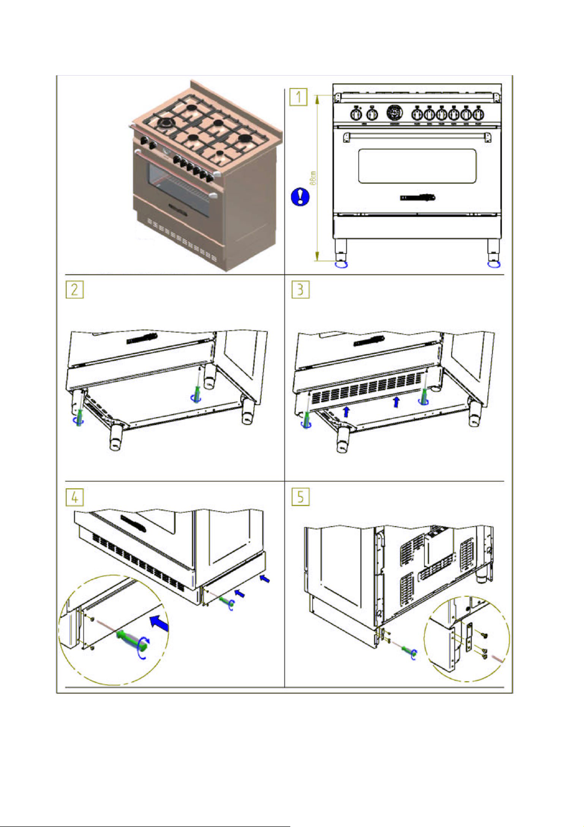
Figure 2
28

Figure 3
29

Figure 4A
30

Figure 4B
31

Figure 6 Figure 7 Figure 8
Figure 9 Figure 10 Figure 11
Figure 12 Figure 13 Figure 14
Figure 15 Figure 16
32

Figure 17 Figure 17 Figure 18
Figure 19 Figure 20
Figure 21 Figure 21 Figure 21A
Figure 21A Figure 22 Figure 23
33

Figure 25 Figure 25 Figure 26
Figure 26 Figure 27
Figure 28 Figure 29
34


ﯽﻗﺮﺑ ﻪﮑﻨﭘ یاراد ﺎهﺮﻓ یاﺮﺑ ﻦﺘﺨﭘ نﺎﻡز
ﻪﻘﻴﻗد عﺎﻔﺕرا اﺮﺡتر °C
70-100 2 160-170
65-90 2 170-180
40-60 2 170-190
65-90 2 160-180
100-130 2 140-160
40-45 2 180-190
30-50 2 170-180
80-100 3 160-170
160-240 3 160-170
120-160 3 160-180
100-160 2 170-180
70-90 2 180
40-50 2 180-200
40-45 2 200-220
40-60 2 170-180
25-35 2 200-230
35-45 2 160-180
20-30 2 180-200
30-40 2 230-250
25-35 2 160
50-60 2 150-180
18-25 2 180-200
30-40 2 170-180
7 3 230-250
40 3 200-220
20 2 200-220
2-3 160-180
یﺰﭘ ﯽﻨﻳﺮﻴﺷ و ﻪچﻮﻠﮐ عاﻮﻧا و ﺎﻬﮑﻴﮐ
درﺎﻳو ﺎﺱ ﺖﺋﻮﮑﺴﺑ زاﺮﭘ ﯽﻧﺮﻓ
کﻮﺥ ندﺮﮐ خﺮﺱ
ﻪﺘﺥا ؤﺎﮔ ندﺮﮐ خﺮﺱ
ﻪﻟﺎﺱﻮﮔ ندﺮﮐ خﺮﺱ
ﻩﺮﺑ ندﺮﮐ خﺮﺱ
وﺎﮔ ندﺮﮐ خﺮﺱ
شﻮﮔﺮﺥ ندﺮﮐ خﺮﺱ
ﯽﮕﻧﺮﻓ شﻮﮔﺮﺥ ندﺮﮐ خﺮﺱ
ﻮﻤﻠﻗﻮﺑ ندﺮﮐ خﺮﺱ
زﺎﻏ ندﺮﮐ خﺮﺱ
کدرا ندﺮﮐ خﺮﺱ
ﯽﭽﻳوﺪﻧﺎﺱ ﮏﻴﮐ
یﺮﻴﻤﺥ تﺎﺠﻴﻨﻳﺮﻴﺷ عاﻮﻧا)شوﺮﺑ(
ﯽﮑﺷاﺮﻴﭘ عاﻮﻧا
دﻮﻟﺁ ﻒﭘ ﻪﭼﻮﻠﮐ
یا ﻩﻮﻴﻣ ﻪﭼﻮﻠﮐ)یرﻮﮕﻧا(
ا ﻪﻟﻮﻟو ﻪﻗرو ﮏﻴﮐی
درﺎﻳوﺎﺱ ﺖﺋﻮﮑﺴﺑ
ﺐﻴﺱ یﺎه ﻩدﺮﺥ زاﺮﭘ ﻪﭼﻮﻠﮐ
ﻩﺪﺷ ﻪﺘﺷﺮﺑ ﭻﻳوﺪﻧﺎﺱ
ﺖﺷﻮﮔ
ندﺮﮐ خﺮﺱﺮﻧ ؤﺎﮔ
ندﺮﮐ خﺮﺱﻪﺟﻮﺟ /غﺮﻣ
ﯽهﺎﻡ
یا ﻩﻮﻴﻣ ﮏﻴﮐ
جﺎﻤﮐ)ﻩدﻮﻟﺁ ﻒﭘ ﮏﻴﮐ(
نﺎﻧ
اﺰﺘﻴﭘ
ﮏﻴﺕﺎﺘﺳا ﯽﻗﺮﺑ ﺮﻓ ﻩدﺎﻔﺘﺳا)ﻦﮐﺎﺳ (
ﻓ ﺎﺑ ناﻮﺗ ﯽﻣ ار ﯽﻗﺮﺑ ﻦﮑﻧﺎﻳﺮﺑداد ﺐﻴﮐﺮﺗ ﯽﻗﺮﺑ ﺎﻳ یزﺎﮔﺮ.
یزﺎﮔﺮﻓ ﺐﻴﮐﺮﺗ ﮏﻳﺎﺑ +دﻮﺷ ﯽﻣ ﻪﺘﺥاﺪﻧا رﺎﮑﺑ ﺮﻓ تﺎﺘﺱﻮﻣﺮﺗ ﻪﻤﮐد زا ﻦﮑﻧﺎﻳﺮﺑ ،ﯽﻗﺮﺑ ﻦﮑﻧﺎﻳﺮﺑ.
2500Wﺪﻨﺷﺎﺑ ﯽﻣ ﯽﻣﺎﻧ .
150°C زا ﺶﻴﺑ نﺪﺷ مﺮﮔ زا ﻪﮑﻨﻳا ﺎﺕ ﺪﻴﻧادﺮﮕﻧ
یاراد یزﺎﮔ ﺮﻓ یﺎﻬﻗﺎﺟا یاﺮﺑ ﯽﻗﺮﺑ ﻦﮑﻧﺎﻳﺮﺑ
ﻢﻬﻡ ﻪﺟﻮﺕ : زا ﺶﻴﺑ ﻪﺑ ار تﺎﺘﺳﻮﻡﺮﺕ ﻪﻤﮐد ،ﯽﻗﺮﺑ ﺮﻓ یﺎﻬﻗﺎﺟا رد ﯽﻗﺮﺑ ﻦﮑﻧﺎﻳﺮﺑ ﻩدﺎﻔﺘﺳا مﺎﮕﻨه
ﺖﺳا ﻩﺪﺷ ﯽﺡاﺮﻃ ﻪﺘﺴﺑ رد ﻦﮐ نﺎﻳﺮﺑ یاﺮﺑ ﺮﻓ ؛دﻮﺷ یﺮﻴﮔﻮﻠﺟ ﺮﻓ ﯽﺋﻮﻠﺟ ﺖﻤﺴﻗ ﺪﺡ.
1 ﺎﻳ 2ﺪﻳراﺬﮕﺑ ﺮﻳز رد ار ﺮﻴﮔ ﻦﻏور ﯽﻨﻴﺱ ﮏﻳ و ﻪﺴﻔﻗ یﻻﺎﺑ ﺮﺑ ار ﺎهاﺬﻏ ،دﻮﺷ ﻪﺘﺷاﺬﮔ .
ﻪﺴﻔﻗﺮﺑ ندﺮﮐ نﺎﻳﺮﺑ : ﺢﻄﺴﺑ ﺪﻳﺎﺑ ﻪﺴﻔﻗ ،درﻮﻣ ﻦﻳا رد
ﻦﮑﻧﺎﻳﺮﺑ ﺶﻳﺎﻣﺮﮔ ﺖﻨﻤﻟاﺪﻴﻨﮐ ﻦﺷور ار .ﺪﻴﺋﺎﻤﻧ ﻢﻴﻈﻨﺗ نﺁ ﻪﻃﻮﺑﺮﻣ ﺖﻟﺎﺤﺑ ار تﺎﺘﺱﻮﻣﺮﺗ.
ﻢﻬﻡ ﻪﺟﻮﺕ :دﻮﺷ ﻪﺘﺷاﺬﮔ ﻪﺘﺴﺑ ﮏﻴﺕﺎﺘﺳا ﯽﻗﺮﺑ ﻦﮑﻧﺎﻳﺮﺑ ﻩدﺎﻔﺘﺳا ﻦﻴﺡ ﺪﻳﺎﺑ ﺮﻓ برد.
راﺪﺸه :دﻮﺷ ﯽﻡ غاد رﺎﻴﺴﺑ قﺎﺟا ﻩﺎﮕﺘﺳد ﻩدﺎﻔﺘﺳا نارود .ﺪﻴﻨﮐ ﺲﻤﻟ ﺖﺳد ﺎﺑ ار ﺮﻓ ﻞﺧاد ﺶﻳﺎﻡﺮﮔ یﺎه ﺖﻨﻤﻟا ﺪﻳﺎﺒﻧ.
ﻪﺟﻮﺕ : ﯽﺳﺮﺘﺳد ﻞﺑﺎﻗ تﺎﻌﻄﻗﺪﻳراﺪﻬﮕﻧ رود ار نﺎﮐدﻮﮐ ۔ﺪﻧدﺮﮔ غاد ﻩدﺎﻔﺘﺳا ﻦﻴﺡ ﺪﻨﻧاﻮﺕ ﯽﻡ.
ﻪﮑﻨﭘ ﺎﺑ ﻦﮑﻧﺎﻳﺮﺑ ﻩدﺎﻔﺘﺳا
راﺮﻗ ﺮﻳز رد ﻦﮐ ﻊﻤﺟ ﻦﻏور ﯽﻨﻴﺱ ﮏﻳ و ﯽﻧﺎﻴﻣ ﺖﻟﺎﺣ ﮏﻴﺑ ﺮﻓ ﻪﺴﻔﻗ ﻪﮐ ﺪﺷﺎﺑ ﯽﻣ ﻪﻨﻴﻬﺑ ندﺮﮐ نﺎﻳﺮﺑ یاﺮﺑ ﻩﮋﻳو ﻞﻤﻋ ﮏﻳ ﻪﮑﻨﭘ ﺎﺑ ﯽﻗﺮﺑ ﻦﮑﻧﺎﻳﺮﺑ
دراد.
2+0 ﺖﻨﻤﻟا ندﺮﮐ ﻦﺷور یاﺮﺑ ﯽﺘﻟﺎﺤﺑ ار
ﺷ ﯽﺡاﺮﻃ ﻪﺘﺴﺑ برد ﺎﺑ ﻪﮑﻨﭘ ﻖﻳﺮﻃ زا ندﺮﮐ نﺎﻳﺮﺑ یاﺮﺑ ﺮﻓ ؛دﻮﺷ یراد دﻮﺧ ﺮﻓ ﯽﺋﻮﻠﺟ ﺪﺡ زا ﺶﻴﺑ نﺪﺷﺖﺳا ﻩﺪ.
ﺮﺑ یﺎﻬﻨﮑﻧﺎﻳﺮﺑ ﺎﺑ ﻩاﺮﻤه یزﺎﮔﺮﻓ یﺎﻬﻗﺎﺟا ﺎﺑ ﯽﻟﺎﻘﺘﻧا ﺪﻴﻠﮐ و ﻦﮑﻧﺎﻳﺮﺑ ﺖﻣﻼﻋ ﻪﺑ ار تﺎﺘﺱﻮﻣﺮﺗ ،ﯽﻗ
2500Wﺪﻴﻨﮐ ﻢﻴﻈﻨﺗ ﻪﮑﻨﭘ رﻮﺗﻮﻣ و ﻦﮑﻧﺎﻳﺮﺑ .
ﺶﻳﺎﻣﺮﮔ
9 ﺪﻴﻠﮐ ،ﯽﻤﻴﻈﻨﺗ ﺖﻟﺎﺣ 9+0 ﮑﻨﻳا ﺎﺗ ﺪﻴﻨﮐ ﻢﻴﻈﻨﺗ موﺰﻟ درﻮﻣ تراﺮﺣ ﻪﺟرد ﻪﺑ ﯽﻗﺮﺑ تﺎﺘﺱﻮﻣﺮﺗ و ﻪﻃﻮﺑﺮﻣ تﺎﺤﺑ ار ﻪ
ﯽﻟﺎﻘﺘﻧا ﺪﻴﻠﮐ یاراد یﺎﻬﻗﺎﺟا ﺎﺑ
ددﺮﮔ ﻦﺷور ﻪﮑﻨﭘ رﻮﺗﻮﻣ و ﻦﮑﻧﺎﻳﺮﺑ ﺶﻳﺎﻣﺮﮔ ﺖﻨﻤﻟا.
ﻢﻬﻡ ﻪﺟﻮﺕ : زا ﺶﻴﺑ ﻪﺑ ﺪﻳﺎﺒﻧ تﺎﺘﺳﻮﻡﺮﺕ ﻪﻤﮐد ،ﯽﻗﺮﺑ ﻦﮑﻧﺎﻳﺮﺑ ندﺮﮐ ﻩدﺎﻔﺘﺳا ﻦﻴﺡ175°C ) ﻦﻴﺑ150° و 200°C( مﺮﮔ زا ﺎﺕ دﻮﺷ ﻩﺪﻴﻧادﺮﮔ

ﯽﻌﻴﺒﻃ تراﺮﺡ لﺎﻘﺘﻧا ﺎﺑ ﯽﻗﺮﺑ ﺮﻓ ﻩدﺎﻔﺘﺳا
ﺎﺑ ﻦﻴﻟوا یاﺮﺑ ﺮﻓ ﻩدﺎﻔﺘﺱا مﺎﮕﻨه ﺮﺜﮐاﺪﺣ یاﺮﺑ ﯽﻠﺥاد یﺎهﺪﻨﺑ زرد زاﻮﺑ عﻮﻧ ﺮه فﺬﺣ ﺮﻃﺎﺨﺑ اﺮﻧﺁ ،ر30 تراﺮﺣ ﻪﺟرد ﺎﺑ ﻪﻘﻴﻗد 250° ﻦﺷور
ﺪﻳراﺬﮕﺑ.
غاﺮﭼ نﺪﺷ شﻮﻣﺎﺥ ﺎﺗ نﺁ ﻞﺥاﺪﺑ ﺎهاﺬﻏ ﻦﺘﺷاﺬﮔ زا ﻞﺒﻗ ًا ﺪ ﻌ ﺑ و ،یﺪﻴﻨﮐ بﺎﺨﺘﻧا دﺎﺘﺱﻮﻣﺮﺗ ﻪﻤﮐد ﻩدﺎﻔﺘﺱا ﺎﺑ ار ﺖﺨﭘ تراﺮﺣ ،یدﺎﻋ ﻩدﺎﻔﺘﺱا نارود
ﺪﻴﺸﮑﺑ رﺎﻈﺘﻧا ﯽﺠﻧرﺎﻧ.
ا رد ﺮﻓ یاراد ﻒﻠﺘﺨﻣ تﺎﻋﺎﻔﺗر5 ﺪﺷﺎﺑ ﯽﻣ رﺎﻴﺷ ) ﻩرﺎﻤﺷ ﻞﮑﺷ23 ( ﺪﻧﻮﺷ ﻩداد ﺎﺟ نﺁ رد ﺎه ﯽﻨﻴﺱ ﺎﻳ ﺎه ﻪﺴﻔﻗ ﻪﮑﻨﻳا ﺎﺗ . ﻒﻴﺜﮐ زا یﺮﻴﮔﻮﻠﺟ ﺮﻃﺎﺨﺑ
دﻮﺷ ﻪﺘﺨﭘ ﯽﻨﻴﺱ رد ﻩﺪﺷ ﻪﺘﺷاﺬﮔ یا ﻪﺴﻔﻗ ﺎﻳ ﯽﻨﻴﺱ ﮏﻳﺮﺑ ﺪﻳﺎﺑ ﺖﺷﻮﮔ ،ﺮﻓ دﺎﻳز نﺪﺷ.
ﯽﻌﻴﺒﻃ تراﺮﺡ لﺎﻘﺘﻧا ﺎﺑ ﯽﻗﺮﺑ ﺮﻓ ﻩدﺎﻔﺘﺳا
ﻪﻘﻴﻗد عﺎﻔﺕرا تراﺮﺡ °C
60-80 3/4 225
60-80 3/4 225
50-60 3/4 250
60-80 3/4 225
40-50 3 225
50-60 3/4 230
40-50 3/4 250
60-80 3 250
50-60 3 250
60-70 3 225
45-60 3/4 250
40-45 3/4 250
15-25 2 200-225
35-40 2 225
50-55 2 175-200
25-30 2 175-200
20-30 2 220-250
30-40 2 180-200
15-20 2 200-220
25-35 2 250
20-30 2 180
40-50 2 180-200
15-20 2 200-220
20-30 2 200-220
5 3 250
30 3 220
20 2 220
یﺰﭘ ﯽﻨﻳﺮﻴﺷ و ﻪچﻮﻠﮐ عاﻮﻧا و ﺎﻬﮑﻴﮐ
درﺎﻳو ﺎﺱ ﺖﺋﻮﮑﺴﺑ زاﺮﭘ ﯽﻧﺮﻓ
کﻮﺥ ندﺮﮐ خﺮﺱ
ﻪﺘﺥا ؤﺎﮔ ندﺮﮐ خﺮﺱ
ندﺮﮐ خﺮﺱﺮﻧ ؤﺎﮔ
ﻪﻟﺎﺱﻮﮔ ندﺮﮐ خﺮﺱ
ﻩﺮﺑ ندﺮﮐ خﺮﺱ
وﺎﮔ ندﺮﮐ خﺮﺱ
شﻮﮔﺮﺥ ندﺮﮐ خﺮﺱ
ﯽﮕﻧﺮﻓ شﻮﮔﺮﺥ ندﺮﮐ خﺮﺱ
ﻮﻤﻠﻗﻮﺑ ندﺮﮐ خﺮﺱ
زﺎﻏ ندﺮﮐ خﺮﺱ
کدرا ندﺮﮐ خﺮﺱ
ندﺮﮐ خﺮﺱﻪﺟﻮﺟ /غﺮﻣ
یا ﻩﻮﻴﻣ ﮏﻴﮐ
ﯽﭽﻳوﺪﻧﺎﺱ ﮏﻴﮐ
یﺮﻴﻤﺥ تﺎﺠﻴﻨﻳﺮﻴﺷ عاﻮﻧا)شوﺮﺑ(
ﯽﮑﺷاﺮﻴﭘ عاﻮﻧا
دﻮﻟﺁ ﻒﭘ ﻪﭼﻮﻠﮐ
یا ﻩﻮﻴﻣ ﻪﭼﻮﻠﮐ)یرﻮﮕﻧا(
یا ﻪﻟﻮﻟو ﻪﻗرو ﮏﻴﮐ
درﺎﻳوﺎﺱ ﺖﺋﻮﮑﺴﺑ
ﺐﻴﺱ یﺎه ﻩدﺮﺥ زاﺮﭘ ﻪﭼﻮﻠﮐ
ﻩﺪﺷ ﻪﺘﺷﺮﺑ ﭻﻳوﺪﻧﺎﺱ
ﺖﺷﻮﮔ
ﯽهﺎﻡ
جﺎﻤﮐ)ﻩدﻮﻟﺁ ﻒﭘ ﮏﻴﮐ(
نﺎﻧ
اﺰﺘﻴﭘ
ددﺮﮔ شﻮﻣﺎﺥ ﯽﺠﻧرﺎﻧ غاﺮﭼ و ﺮﺱﺮﺑ ﻩﺪﺷ بﺎﺨﺘﻧا تراﺮﺣ ﻪﺟرد ﻪﺑ ﺮﻓ ﻪﮐ ﺪﻴﻨﮐ نﺎﻨﻴﻤﻃا ،ﺎهاﺬﻏ ﻦﺘﺨﭘ زﺎﻏﺁ زا ﻞﺒﻗ . ﺖﻨﻤﻟا یاراد ﺮﻓ عﻮﻧ ﻦﻳا
ﻪﺘﻓﺮﮔ راﺮﻗ ﯽﻘﻓا ﺖﻟﺎﺤﺑ یرﺎﺸﻓ یاﻮه شدﺮﮔ یاﺮﺑ ﻪﮑﻨﭘ و ،ﺪﺷﺎﺑ ﯽﻣ ﻞﮑﺷ دﺮﮔ ﯽﻠﺥاد ﺶﻳﺎﻣﺮﮔ . ،ﻞﻤﻋ لﻮﺻا ﻦﻳا سﺎﺱاﺮﺑ ار یا ﻪﮑﻨﭘ ﺮﻓ ﮏﻳ
دﺮﺑ رﺎﮑﺑ اﺬﻏ ﻪﻘﻳاذ رد یﺮﻴﻴﻐﺗ نوﺪﺑ ،نﺎﻣﺰﻤه رﻮﻄﺑ ﺎهاﺬﻏ ﻒﻠﺘﺨﻣ عاﻮﻧا ﻦﺘﺨﭘ یاﺮﺑ ناﻮﺗ ﯽﻣ . یﺎهﺮﺘﻠﻴﻓ ﺎﺑ ﻩاﺮﻤه ﺐﻘﻋ ﺖﻤﺴﻗ رد ﺎﻬﻟﺪﻣ ﯽﻀﻌﺑ
ﺖﺱا ﻩﺪﺷ یراﺬﮔ ﺖﻣﻼﻋ ﺮﻴﺗ ﮏﻳﺎﺑ ﻪﮐ ،ﺪﻴﻨﮐ لﺎﻤﻋا ﺮﻴﺷ یﻻﺎﺑ یﻮﺱ ار ﯽﻔﻴﻌﺿ رﺎﺸﻓ . رﻮﻄﺑ ﺶﻳﺎﻣﺮﮔ ﻪﮐ ﺪﻨﮐ ﯽﻣ ﻦﻴﻤﻀﺗ مﺮﮔ یاﻮه شدﺮﮔ
ﻪﮑﻨﭘ ﺎﺑ ﯽﻗﺮﺑ ﺮﻓ ﻩدﺎﻔﺘﺳا
ﺮﺜﮐاﺪﺣ یاﺮﺑ ار نﺁ ،رﺎﺑ ﻦﻴﻟوا یاﺮﺑ ﺮﻓ لﺎﻤﻌﺘﺱا مﺎﮕﻨه30 تراﺮﺣ ﻪﺟرد ﺎﺑ ﻪﻘﻴﻗد 250° ﻨﻳا ﺎﺗ ﺪﻳراﺬﮕﺑ ﻦﺷور فﺬﺣ ﯽﻠﺥاد یﺎهﺪﻨﺑزرد زاﻮﺑ ﻪﮑ
دﻮﺷ.
دراد ﯽﻣ ﻪﮕﻧ ندﺮﮐ خﺮﺱ ﻦﻴﺣ ار بﺮﭼ ﻪﮐ ﺪﻧا ﻩﺪﺷ ﺐﺼﻧ ﯽﻧﺪﺷ اﺪﺟ یﺰﻠﻓ . دﻮﺷ ﯽﺸﮑﺑﺁ ﻞﻣﺎﮐ رﻮﻄﺑ ﺪﻳﺎﺑ ﺮﺘﻠﻴﻓ ﻦﻳا . ﻦﺘﺥﺎﺱ اﺪﺟ یاﺮﺑ ،یﺰﻠﻓ ﺮﺘﻠﻴﻓ
ﺖﺱا ﻩﺪﺷ ﺶﺨﭘ راﻮﻤه . ددﺮﮔ مﺮﮕﺸﻴﭘ ﺎه ﯽﻨﻴﺱ ﻦﺘﺷاﺬﮔ زا ﻞﺒﻗ ﺪﻳﺎﺑ ﺮﻓ ،ﻒﻴﻄﻟ یﺎهاﺬﻏ ﻦﺘﺨﭘ درﻮﻣ رد ﺎﻣا ،دراﺪﻧﺮﻓ ندﺮﮐ مﺮﮕﺸﻴﭘ ﻪﺑ جﺎﻴﺘﺣا .
ﻢﺘﺴﻴﺱ تراﺮﺣ لﺎﻘﺘﻧا ﻪﮑﻨﭘ ﻖﻳﺮﻃ زا ﻦﺘﺨﭘ )ﺶﻳﺎﻣﺮﮔ ( ﺪﻨﮐ ﯽﻣ ضﻮﻋ یﺪﺤﺑ ار ﺰﭘو ﺖﺨﭘ ﯽﺘﻨﺱ مﺎﻬﻓا . نارود ندﺮﮐ ﺮﻳزو ور ﻪﺑ جﺎﻴﺘﺣا ﺖﺷﻮﮔ
ﺪﺷﺎﺑ ﯽﻤﻧ ﺦﻴﺱ ﻪﺑ جﺎﻴﺘﺣا نﺎﻳﺮﺑ ﺖﺨﭘ یاﺮﺑ و دراﺪﻧ ﻦﺘﺨﭘ .ﺖﺷاﺬﮔ ﻪﺴﻔﻗ یور ﺮﺑ ﺪﻳﺎﺑ ﻂﻘﻓ ار ﺖﺷﻮﮔ.

ﻩرﺎﮐ ﺪﻨچ یﺎﻬﻗﺎﺟا یاﺮﺑ ﯽﻗﺮﺑ تﺎﺘﺴﻡﺮﺕ ﻩدﺎﻔﺘﺳا
دوﺪﺤﺑ ار ﺮﻓ ﻞﺥاد تراﺮﺣ لﺪﻣ ﺮه رد ﻩﺪﺷ ﻢهاﺮﻓ تﺎﺘﺱﻮﻣﺮﺗ50°C ﺎﺗ 250°Cدراد ﯽﻣ ﻪﮕﻧ ﺖﺑﺎﺙ.
ﻮﻠﺟ ﻪﺤﻔﺻ ﺮﺑ ﻩﺪﺷ پﺎﭼ ﺖﻣﻼﻋ ﺎﺑ یﺰﻠﻓ ﻪﻘﻠﺣ ﺮﺑ ﻪﺟرد ﻦﺘﺥﺎﺱ ﻒﻳدﺮﻤه ﺮﻃﺎﺨﺑ ار ﻪﻤﮐد) ﻞﮑﺷ25 ( ﺪﻴﻧادﺮﮕﺑ دﺮﮕﺘﻋﺎﺱ ﺖﻤﺴﺑ . غاﺮﭼ ﮏﻳ
C ﺾﺤﻣ و ددﺮﮔ ﯽﻣ شﻮﻣﺎﺥ ﺪﻳﺎﻤﻧ زوﺎﺠﺗ
C دﻮﺷ ﯽﻣ ﻦﺷور . رد ﺪﻴﻠﮐ ﺮﮔا دزاﺪﻧا رﺎﮑﺑ ﯽﺗرﻮﺻ رد ﻂﻘﻓ ار ﺶﻳﺎﻣﺮﮔ یﺎﻬﺘﻨﻤﻟا ﺪﻧاﻮﺗ ﯽﻣ تﺎﺘﺱﻮﻣﺮﺗ
زا ﺮﺗ ﻦﻴﺋﺎﭙﺑ تراﺮﺣ ﻦﺘﻓﺎﻳ ﻞﻴﻠﻘﺗ10°
ﮑﻳ ﯽﮔدﺮﮐرﺎﮐ ﺖﻟﺎﺣﺪﺷﺎﺑ ﺶﻳﺎﻣﺮﮔ ﺖﻨﻤﻟا زا ﯽ . ﺖﻟﺎﺣ ﻪﺑ ﺪﻴﻠﮐ ﺮﮔا0ﺖﺥاﺪﻧا ﺪهاﻮﺨﻧ رﺎﮑﺑ ار ﺶﻳﺎﻣﺮﮔ یﺎه ﺖﻨﻤﻟا تﺎﺘﺱﻮﻣﺮﺗ ،ﻩﺪﺷ ﻪﺘﺷاﺬﮔ .
رﻮﺘﮑﻠﺳ ﻩدﺎﻔﺘﺳا9-ﺮﻓ ﻩرﺎﮐ ﺪﻨچ ﻪﻤﻴﻈﻨﺕ
ﯽﻟﺎﻘﺘﻧا ﺪﻴﻠﮐ9+0 دﻮﺷ ﯽﻣ ﻩدﺎﻔﺘﺱا ﺶﻳﺎﻣﺮﮔ یﺎه ﺖﻨﻤﻟا و ﻪﮑﻨﭘ رﻮﺗﻮﻣ ،تﺎﺘﺱﻮﻣﺮﺗ ﺎﺑ ﻩاﺮﻤه ،لﺮﺘﻨﮐ یاﺮﺑ ﻩرﺎﮐ ﺪﻨﭼ یﺎهﺮﻓ یاﺮﺑ . ﻦﺷور یاﺮﺑ
ﺪﻴﻠﮐ ﺮه ﻪﻤﮐد ود ﺮه ،ﺎه ﺖﻨﻤﻟا ندﺮﮐ9+0 ﺎﻳ غاﺮﭼ ﻂﻘﻓ و دﺮﮐ ﺪهاﻮﺤﻧ رﺎﮐ ﺮﻓ ،ﺪﺷ ﻩﺪﻧادﺮﮔ ﻪﻤﮐد ﮏﻳ ﻂﻘﻓ ﺮﮔا ؛ﺪﻧﻮﺷ ﻩﺪﻧادﺮﮔ ﺪﻳﺎﺑ تﺎﺘﺱﻮﻣﺮﺗ و
ﺪﻨﺘﻓا ﯽﻣ رﺎﮑﺑ ﻪﮑﻨﭘرﻮﺗﻮﻣ . یاراد ﯽﻗﺮﺑ ﺮﻓ4 ﺪﻨﺷﺎﺑ ﯽﻣ ﺶﻳﺎﻣﺮﮔ ﺖﻨﻤﻟا . ﻠﮐ ﻪﻤﮐد ؛دﺮﮔ ﺖﻨﻤﻟا ﮏﻳ و ﯽﺋﻻﺎﺑ ﺖﻨﻤﻟا ود ،ﺮﻳز ﺖﻨﻤﻟا ﮏﻳ ﯽﻟﺎﻘﺘﻧا ﺪﻴ
ﻪﺘﺸﮔ ﻦﺷور ﺖﻨﻤﻟا ﻪﮐ ﺪهد نﺎﺸﻧ ﻩﺪﺷ ﻦﺷور ﯽﺠﻧرﺎﻧ غاﺮﭼ ﺎﺗ ﺪﻴﻧادﺮﮕﺑ یﺪﺤﺑ ار . زا ﯽﮑﻴﺑ ار ﯽﻟﺎﻘﺘﻧا ﺪﻴﻠﮐ ﺮﮔا9 ﺮﻗ دﺮﮐ ﻞﻤﻋ ﺖﻟﺎﺣ ،ﺪﻴهد را
دﻮﺷ ﯽﻣ ﻦﺷور ﺮﻓ غاﺮﭼ نﻮﭽﻤه و ددﺮﮔ ﯽﻣ لﺎﻌﻓ ﻪﻃﻮﺑﺮﻣ ﺶﻳﺎﻣﺮﮔ ﺖﻨﻤﻟا . دﺮﮐ ﻞﻤﻋ یاﺮﺑ ﺶﻳﺎﻣﺮﮔ یﺎه ﺖﻨﻤﻟا و تراﺮﺣ ﻪﺟرد ﻪﮑﻨﻳا زا ﺪﻌﺑ
رﺎﮐ ﯽﺠﻧرﺎﻧ غاﺮﭼ نﺪﺷ شﻮﻣﺎﺥ و ﻦﺷور ﺮﻓ ﯽﮔدﺮﮐرﺎﮐ ﻦﻴﺣ ﻦﻳﺮﺑﺎﻨﺑ ،ﺪﺘﻓا ﯽﻣ رﺎﮑﺑ تﺎﺘﺱﻮﻣﺮﺗ ﻖﻳﺮﻃ زا ﺮﻓ ﺶﻳﺎﻣﺮﮔ یﺎه ﺖﻨﻤﻟا ،ﺪﺷ بﺎﺨﺘﻧا
ﺪهاﻮﺥ یدﺎﻋدﻮﺑ .
ﻪﺑ ار ﯽﻟﺎﻘﺘﻧا ﺪﻴﻠﮐ ﻪﻤﮐد ،ﯽﻗﺮﺑ ﺮﻓ ندﺮﮐ شﻮﻣﺎﺥ یاﺮﺑ0 ﺪﻳﺎﻤﻧ یﺮﻴﮔﻮﻠﺟ ﺎه ﺖﻨﻤﻟا ندﺮﮐ غاد زا تﺎﺘﺱﻮﻣﺮﺗ ﻪﮑﻨﻳا ﺎﺗ ﺪﻴﻧادﺮﮕﺑ . یﺎه ﺖﻨﻤﻟا
ﺖﺥﺎﺱ ﻦﺷور ﯽﻟﺎﻘﺘﻧا ﺪﻴﻠﮐ زا ناﻮﺗ ﯽﻣ ار ﺮﻓ غاﺮﭼ و ﻪﮑﻨﭘ رﻮﺗﻮﻣ ﺎﻣا ،ﺪﻧﻮﺷ ﯽﻣ لﺎﻌﻓ ﺮﻴﻏ ﺶﻳﺎﻣﺮﮔ.
یاراد ﺪﻴﻠﮐ9 یاﺮﺑ ﯽﻤﻴﻈﻨﺗ ﺖﻟﺎﺣ 9ﺨﻣ عﻮﻧ ﺪﺷﺎﺑ ﯽﻣ ﺮﻓ یزاﺪﻧا رﺎﮐ ﻒﻠﺘ:
ﻧ ﻪﺑ ﻩﺪﺷ بﺎﺨﺘﻧا ﻪﺟرد زا تراﺮﺣ ﻪﮑﻴﻣﺎﮕﻨه و ﺪﻨﮐ ﯽﻣ رﺎﮐ تﺎﺘﺱﻮﻣﺮﺗ ﻪﮐ ﺪهد ﯽﻣ نﺎﺸﻧ ﯽﺠﻧرﺎ10°
) ﻞﮑﺷ26 ( ﺪﻨﮐ ﺖﻘﺑﺎﻄﻣ یﺰﻠﻓ ﻪﻘﻠﺣ ﺮﺑ ﺖﻣﻼﻋ ﺎﺑ ﺶﻳﺎﻣﺮﮔ ﺖﻨﻤﻟا ﻪﮑﻨﻳا ﺎﺗ ﺪﻴﻧادﺮﮕﺑ ار . تﺎﺘﺱﻮﻣﺮﺗ ﻪﻤﮐد ﺪﻳﺎﺑ ﺖﻨﻤﻟا ﻦﻳا ﻦﺘﺥاﺪﻧا رﺎﮑﺑ یاﺮﺑ ﺎﻣا و
ﺎﻳ ؛ﺖﺱا ﻦﺷور ﺮﻓ غاﺮﭼ ﻂﻘﻓ ﻪﮐ ﺪهد ﯽﻣ نﺎﺸﻧ
ﺎﻳ ﺶﻳﺎﻣﺮﮔ ﺖﻨﻤﻟا ﻪﮐ ﺪهد ﯽﻣ نﺎﺸﻧ 1200W ﺶﻳﺎﻣﺮﮔ ﺖﻨﻤﻟا و ﯽﻨﻴﺋﺎﭘ 1800W؛ﺪﻨﺷﺎﺑ ﯽﻣ ﻦﺷور ﯽﺟرﺎﺥ ﯽﺋﻻﺎﺑ
ﺎﻳ ﺪهد ﯽﻣ نﺎﺸﻧ ﺶﻳﺎﻣﺮﮔ ﺖﻨﻤﻟا ﻂﻘﻓ ﻪﮐ 1200W؛ﺖﺱا ﻦﺷور ﯽﺋﻻﺎﺑ
ﺎﻳ ﺪهد ﯽﻣ نﺎﺸﻧ ﺶﻳﺎﻣﺮﮔ ﺖﻨﻤﻟا ﻂﻘﻓ ﻪﮐ 1800W؛ﺖﺱا ﻦﺷور ﯽﻨﻴﺋﺎﭘ
ﺎﻳ ﺪهد ﯽﻣ نﺎﺸﻧ ﺶﻳﺎﻣﺮﮔ ﺖﻨﻤﻟا ﻂﻘﻓ ﻪﮐ 1800W ﺖﺱا ﻦﺷور ﻦﮑﻧﺎﻳﺮﺑ)ﺪﻴﻨﮐ ﻊﺟاﺮﻣ نﺁ صﻮﺼﺨﻣ ﺖﻤﺴﻗ ﻪﺑ(؛
ﺎﻳ ﺪهد ﯽﻣ نﺎﺸﻧ ﺶﻳﺎﻣﺮﮔ ﺖﻨﻤﻟا ﻪﮐ 1200W ﮑﻧﺎﻳﺮﺑ ﺶﻳﺎﻣﺮﮔ ﺖﻨﻤﻟا و ﯽﺟرﺎﺥ ﯽﺋﻻﺎﺑ ﻦ1800W ﯽﻣ ﻦﺷور
ﺎﻳ ﺪهد ﯽﻣ نﺎﺸﻧ ﺶﻳﺎﻣﺮﮔ ﺖﻨﻤﻟا ﻪﮐ 1200W ﻦﮑﻧﺎﻳﺮﺑ ﺶﻳﺎﻣﺮﮔ ﺖﻨﻤﻟا ،ﯽﺟرﺎﺥ ﯽﺋﻻﺎﺑ 1800W ﻪﮑﻨﭘ رﻮﺗﻮﻣ و
ﺪﻨﺷﺎﺑ ﯽﻣ ﻦﺷور)ﺪﻴﻨﮐ ﻊﺟاﺮﻣ صﻮﺼﺨﻣ ﺖﻤﺴﻘﺑ(؛
ﺎﻳ ﺪهد ﯽﻣ نﺎﺸﻧ ﺶﻳﺎﻣﺮﮔ ﺖﻨﻤﻟا ﻪﮐ 3000Wﻨﭘ رﻮﺘﻣو دﺮﮔ ﺪﻨﺷﺎﺑ ﯽﻣ ﻦﺷور ﻪﮑ .
ﺎﻳ ﺪهد ﯽﻣ نﺎﺸﻧ ﺖﺱا ﻦﺷور ﻪﮑﻨﭘرﻮﺗﻮﻣ ﻂﻘﻓ ﻪﮐ .
زا ﯽﮑﻴﺑ ﻪﻤﮐد ﻪﮑﻴﻣﺎﮕﻨه9ﺪهد نﺎﺸﻧ ار ﺮﻓ ﻞﺥاد ژﺎﺘﻟو ﺎﺗ ﺪﺷﺎﺑ ﯽﻣ ﻦﺷور ﻪﺸﻴﻤه ﺮﻓ غاﺮﭼ ،دﻮﺷ ﯽﻣ ﻩﺪﻴﻧادﺮﮔ رﻮﮐﺬﻣ ﺖﻟﺎﺣ .
- ﺖﻣﻼﻋ
- ﺖﻣﻼﻋ
- ﺖﻣﻼﻋ
- ﺖﻣﻼﻋ
- ﺖﻣﻼﻋ
- ﺖﻣﻼﻋ
ﺪﻨﺷﺎﺑ)ﺪﻴﻨﮐ ﻊﺟاﺮﻣ نﺁ صﻮﺼﺨﻣ ﺖﻤﺴﻘﺑ(؛
- ﺖﻣﻼﻋ
- ﺖﻣﻼﻋ
ﺖﻣﻼﻋ

یزﺎﮔ ﻦﮑﻧﺎﻳﺮﺑ ﻩدﺎﻔﺘﺳا)ﮏﺕ لﺮﺘﻨﮐ(
زﺎﮔﺮﻓ ﺎﺑ ﻂﻘﻓ ناﻮﺗ ﯽﻣ ار یزﺎﮔ ﻦﮑﻧﺎﻳﺮﺑ داد ﺐﻴﮐﺮﺗ ی . دﺮﮕﺘﻋﺎﺱ یﻮﺴﺑ دﺮﮕﺘﻋﺎﺱ دﺎﭘ یﺎﺠﺑ ﺎﻣا ،دﻮﺷ ﯽﻣ لﺮﺘﻨﮐ یزﺎﮔ ﺮﻓ ﻪﻤﮐد نﺎﻤه ﺎﺑ نﺁ
دﻮﺷ ﻩﺪﻨﻳادﺮﮔ) ﺪﻴﻨﮐ ﻊﺟاﺮﻣ یزﺎﮔﺮﻓ ﻩدﺎﻔﺘﺱا تارﻮﺘﺱد ﻪﺑ( ﺪﻨﮐ اﺪﻴﭘ ﺖﻘﺑﺎﻄﻣ رﻮﺗﺎﮑﻳﺪﻧا ﺎﻳ ﺖﻣﻼﻋ ﻪﮐ ، . ﻪﺟرد ﺮﺜﮐاﺪﺣ ﻪﺑ ﻪﺸﻴﻤه ﻦﮑﻧﺎﻳﺮﺑ ﻦﮑﻓا ﻪﻠﻌﺷ
ﻤﻧ ﻞﻗاﺪﺣ ﻪﺟرد یاراد ﻦﻳﺮﺑﺎﻨﺑ و ﺪﻨﮐ ﯽﻣ رﺎﮐ ﺪﺷﺎﺑ ﯽ . ﯽﻣ یﺮﻴﮔﻮﻠﺟ ﺮﻓ زا ﻪﻠﻌﺷ نﺪﺷ جرﺎﺥ زا ﻪﮐ ﻩﺪﺷ ﺰﻬﺠﻣ ﯽﻨﻤﻳا ﻪﻠﻴﺱو ﮏﻳﺎﺑ نﺁ ،ﻪﻓﺎﺿا ﻪﺑ
ﺪﻨﮐ .ﺖﺥﺎﺱ ﻦﺷور ﻒﻠﺘﺨﻣ قﺮﻄﺑ ناﻮﺗ ﯽﻣ ﺰﻴﻧ ار یزﺎﮔ ﻦﮑﻧﺎﻳﺮﺑ:
- ﯽﺘﺳد ﻦﺷور : ددﺮﮔ ﻒﻳدﺮﻤه رﻮﺗﺎﮑﻳﺪﻧا ﺎﻳ ﻪﻃﻮﺑﺮﻣ ﺖﻣﻼﻋ ﻪﮑﻨﻳا ﺎﺗ ﺪﻴﻧادﺮﮕﺑ ار ﻪﻤﮐد ،ﺪﻴﻨﮐ زﺎﺑ ﻞﻣﺎﮐ رﻮﻄﺑ ار ﺮﻓ برد :ندﺮﺸﻓ ﻦﻴﺣ ؛و ،ﻪﻤﮐد
ﺪﻳراﺪﻬﮕﻧ ﻦﮑﻓا ﻪﻠﻌﺷ یﻮﻠﻬﭙﺑ ار ﻦﺷور ﺖﻳﺮﺒﮐ ﮏﻳ نﺎﻣﺰﻤه رﻮﻄﺑ . زا ﺪﻌﺑ و ددﺮﮔ ﻦﺷور ًﻼ ﻣ ﺎ ﮐ ﻦﮑﻓا ﻪﻠﻌﺷ ﻪﮐ ﺪﻴﻨﮐ نﺎﻨﻴﻤﻃا10 ار ﻪﻤﮐد ﻪﻴﻧﺎﺙ
ﺪﻳرﺎﺸﻔﺑ ار تﺎﺘﺱﻮﻣﺮﺗ ﻪﻤﮐد ًا ﺪ ﻌ ﺑ ،ددﺮﮔ) ﻪﻤﮐد ﻖﻳﺮﻃ زا ﯽﻧز ﻪﻗﺮﺟ ﺎﺑ ﺎﻬﻟﺪﻣ .( ﺎﺗ دﻮﺷ ﻦﺷور ﻞﻣﺎﮐ رﻮﻄﺑ ﻦﮑﻓا ﻪﻠﻌﺷ ﻪﮑﻨﻳا زا ﺪﻌﺑ10 رﺎﻈﺘﻧا ﻪﻴﻧﺎﺙ
ﺪﻴﻨﮐ ﺎهر ار ﻪﻤﮐد ًا ﺪ ﻌ ﺑ و ﺪﻴﺸﮐ . ﺪﻴﻨﮐ نﺎﻨﻴﻤﻃا ﺪﻴﻨﮐ راﺮﮑﺗ ار ﻞﻤﻋ ﻦﻳا ﻪﻧﺮﮔو ،ﺪﻧﺎﻤﺑ ﻦﺷور ﻦﮑﻓا ﻪﻠﻌﺷ ﻪﮐ . نز ﻪﻗﺮﺟ نوﺪﺑ ﺎﻬﻗﺎﺟا صﻮﺼﺥ رد
ﺎﺗ ،ﺪﻴهد رﺎﺸﻓ ار ﻪﻗﺮﺟ ﺖﻣﻼﻋ یاراد ﺪﻴﻠﮐو تﺎﺘﺱﻮﻣﺮﺗ ﻪﻤﮐد ،یا ﻪﻤﮐد10 ﻩﺪﺷ ﻦﺷور ﻞﻣﺎﮐ رﻮﻄﺑ ﻦﮑﻓا ﻪﻠﻌﺷ ﻪﮑﻨﻳا زا ﺪﻌﺑ و ﺪﻴﺸﮑﺑ رﺎﻈﺘﻧا ﻪﻴﻧﺎﺙ
ﺪﻳزﺎﺱ ﺎهر ار ﻪﻤﮐد . ﻦﮑﻓا ﻪﻠﻌﺷ ﻪﮐ ﺪﻴﻨﮐ نﺎﻨﻴﻤﻃاﺪﻧﺎﻤﺑ ﻦﺷور .دﻮﺷ راﺮﮑﺗ ﻞﻤﻋ ﻦﻳا ترﻮﺻ نﺁ ﺮﻴﻏ رد.
ﺪﻴﻨﮐ ﺎهر .دﻮﺷ اﺮﮑﺗ رﻮﮐﺬﻣ ماﺪﻗا ﻪﻧﺮﮔو ،ﺪﻧﺎﻤﺑ ﻦﺷور ﻦﮑﻓا ﻪﻠﻌﺷ ﻪﮐ ﺪﻴﻨﮐ نﺎﻨﻴﻤﻃا.
- ﯽﻗﺮﺑ ﻦﺷور: ﺎﺑ ًﻼ ﻣ ﺎ ﮐ ار ﺮﻓ برد ،ترﻮﺻ ﻦﻳا رد ﻒﻳدﺮﻤه رﻮﺘﮑﻳﺪﻧا ﻪﻃﻮﺑﺮﻣ ﺖﻣﻼﻋ ﺎﺑ ﻪﮑﻨﻳا ﺎﺗ ﺪﻴﻧادﺮﻴﮕﺑ ﯽﺘﻴﻟﺎﺤﺑ ﻩدﺮﺸﻓ ار ﻪﻤﮐد ،ﺪﻴﻨﮐ ز
راﺪﺸه:دﻮﺷ ﻦﺷور ﻞﻡﺎﮐ زﺎﺑ برد ﺎﺑ ﺪﻳﺎﺑ ﻦﮑﻧﺎﻳﺮﺑ ،ﺮﻓ درﻮﻡ رد .
دﺮﺑ رﺎﮑﺑ ﺰﭙﺑﺎﺒﮐ ﻩدﺎﻔﺘﺱا ﺎﺑﺎﻳﺮﻓ ﻪﺴﻔﻗ ﺮﺑ ﺎهاﺬﻏ ندﺮﮐ نﺎﻳﺮﺑ یاﺮﺑ ناﻮﺗ ﯽﻣ ار یزﺎﮔ ﻦﮑﻧﺎﻳﺮﺑ.
ﻪﺴﻔﻗ یورﺮﺑ ندﺮﮐ نﺎﻳﺮﺑ: ﺢﻄﺱ ﺮﺑ ﻩﺪﺷ ﻢهاﺮﻓ ﻪﺴﻔﻗ ،صﻮﺼﺥ ﻦﻳا رد 1 ﺎﻳ 2 ﺟ ،ﺪﻧﻮﺷ ﯽﻣ ﻪﺘﺷاﺬﮔ نﺁ یورﺮﺑ نﺎﻳﺮﺑ درﻮﻣ یﺎهاﺬﻏ و ﻩﺪﺷ ﻩدادﺎ
دﻮﺷ ﻊﻤﺟ نﺁ یور اﺬﻏ زا ﻩﺪﻴﮑﭼ بﺁ ﻪﮑﻨﻳا ﺎﺗ دﻮﺷ ﯽﻣ ﻪﺘﺷاﺬﮔ ﻞﺥاﺪﺑ ﯽﻨﻴﺋﺎﭘ حﻮﻄﺱ ﺮﺑ ﯽﻨﻴﺱ ﻪﮑﻴﻟﺎﺣ رد.
ﺪﻴﺋﺎﻤﻧ ﻦﺷور ﻻﺎﺑ ﻩﺪﺷ ﺮﮐذ تارﻮﺘﺱد ﺐﺴﺣﺮﺑ ار ﻦﮑﻧﺎﻳﺮﺑ ﻦﮑﻓا ﻪﻠﻌﺷ ًا ﺪ ﻌ ﺑ.
ﻢﻬﻡ ﻪﺟﻮﺕ:ﺘﺴﺑ برد ﺎﺑ ﻪﺴﻔﻗ ﺮﺑ ﻪﺸﻴﻤه ار ﺎهاﺬﻏ ﺪﻴﻨﮐ نﺎﻳﺮﺑ ﻪ.
راﺪﺸه:ﺪﻧﻮﺷ غاد رﺎﻴﺴﺑ ﺪﻨﻧاﻮﺕ ﯽﻡ سﺮﺘﺳد ﻞﺑﺎﻗ تﺎﻌﻄﻗ اﺬﻏ نﺪﺷ نﺎﻳﺮﺑ ﻦﻴﺡ .ﺪﻳراﺪﻬﮕﻧ رود قﺎﺟا ﻩﺎﮕﺘﺳد زا اﺬﻏ ﺖﺨﭘ ﻦﻴﺡ ار نﺎﮐدﻮﮐ.
راﺪﺸه:ﺪﻧدﺮﮔ غاد رﺎﻴﺴﺑ ﻦﮑﻧﺎﻳﺮﺑ ﻦﻴﺡ ﺪﻨﻧاﻮﺕ ﯽﻡ سﺮﺘﺳد ﻞﺑﺎﻗ تﺎﻌﻄﻗ .ﺪﻳراﺪﻬﮕﻧ رود قﺎﺟا ﻩﺎﮕﺘﺳد زا ﺖﺨﭘ ﻦﻴﺡ ار نﺎﮐدﻮﮐ.
ﺎﮔﺮﻓ ﻩدﺎﻔﺘﺳاﻪﻟوﺮﺘﺘﮐ ود لﺪﻡ یاﺮﺑ یز
داد ﺐﻴﮐﺮﺗ یزﺎﮔ ﺮﻓ ﺎﺑ ﻂﻘﻓ ناﻮﺗ ﯽﻣ ار یزﺎﮔ ﻦﮑﻧﺎﻳﺮﺑ.
دراد ﻖﻠﻌﺗ ﻪﻤﮐد ماﺪﮐ ﺎﺑ ﻦﮑﻓا ﻪﻠﻌﺷ ماﺪﮐ ﻪﮐ ﺖﺱا نﺁ ﻩﺪﻨهد نﺎﺸﻧ ﻪﮐ ﻩﺪﺷ ﮏﺣ ﻪﻤﮐد ﺮه یﻻﺎﺑ لﺮﺘﻨﮐ ﻪﺤﻔﺻ یورﺮﺑ ﻪﺸﻘﻧ ﮏﻳ . ار یزﺎﮔ ﻦﮑﻧﺎﻳﺮﺑ
ﺻﻮﺼﺥ و ﻩﺎﮕﺘﺱد عﻮﻧ ﻪﺑ ﺮﺼﺤﻨﻣ ﺎﻣا دﺮﮐ ﻦﺷور ﻒﻠﺘﺨﻣ قﺮﻄﺑ ناﻮﺗ ﯽﻣﺪﺷﺎﺑ ﯽﻣ نﺁ ﻩﮋﻳو تﺎﻴ:
ﯽﺘﺳد ﻦﺷور) قﺮﺑ ﻊﻄﻗ مﺎﮕﻨه ﯽﺘﺡ ﺖﺳا ﺮﻳﺬﭘ نﺎﮑﻡا ﻪﺸﻴﻤه :( یزﺎﮔ ﻦﮑﻧﺎﻳﺮﺑ ﺎﺑ ﻪﮐ دﺮﮕﺘﻋﺎﺱ دﺎﭘ ﺖﻤﺴﺑ ار ﻪﻤﮐد ،ﺪﻴﻨﮐ زﺎﺑ ًﻼ ﻣ ﺎ ﮐ ار ﺮﻓ برد
-
ﺪﻴﻨﮐ ﻢﻴﻈﻨﺗ ﺮﺜﮐاﺪﺣ ﺖﻟﺎﺤﺑ ﻩﺪﺷ ﮏﺣ ﻩرﺎﺘﺱ ﻪﺑ و ﺪﻴﻧادﺮﮕﺑ دراد ﺖﻘﺑﺎﻄﻣ) ﻞﮑﺷ ﺪﻨﻠﺑ ﻪﻠﻌﺷ17 ( ﻳ ﻩدﺮﺸﻓ ار ﻪﻤﮐد لﺎﺣ ﻦﻴﺣ رد و ﻦﺷور ﺖﻴﻳﺮﺒﮐ ﮏ
ﺪﻳراﺬﮕﺑ ﻦﮑﻓا ﻪﻠﻌﺷ یور ﺮﺑ ار . زا ﺪﻌﺑ و ﻪﺘﺸﮔ ﻦﺷور ًﻼ ﻣ ﺎ ﮐ ﻦﮑﻓا ﻪﻠﻌﺷ ﻪﮐ ﺪﻴﻨﮐ نﺎﻨﻴﻤﻃا10 ﺪﻳزﺎﺱ ﺎهر ار ﻪﻤﮐد ﻪﻴﻧﺎﺙ . ﻪﻠﻌﺷ ﻪﮐ ﺪﻴﻨﮐ نﺎﻨﻴﻤﻃا
ﻩﺪﻧﺎﻤﺑ ﻦﺷور ﻦﮑﻓا .دﻮﺷ راﺮﮑﺗ رﻮﮐﺬﻣ ماﺪﻗا ﺪﻳﺎﺑ ترﻮﺻ نﺁ ﺮﻴﻏ رد.
ﯽﻗﺮﺑ ﻦﺷور : ﻳراﺬﮕﺑ زﺎﺑ ﻻﺎﮐ ار ﺮﻓ برد ﯽﺻﻮﺼﺥ ﻦﻳا رد ،دﻮﺷ ﻒﻳدﺮﻤه رﻮﺗﺎﮑﻳﺪﻨﻳا ﺎﻳ ﻪﻃﻮﺑﺮﻣ ﺖﻣﻼﻋ ﻪﮑﻨﻳا ﺎﺗ ﺪﻴﻧادﺮﮕﺑ ﻩدﺮﺸﻓ ار ﻪﻤﮐد ،ﺪ
-
تﺎﺘﺱﻮﻣﺮﺗ ﻪﻤﮐد ًا ﺪ ﻌ ﺑ) ﻪﻤﮐد ﻖﻳﺮﻃ زا ﻪﻗﺮﺟ ﺎﺑ ﺎﻬﻟدﻮﻣ رد ( ﺪﻴهد رﺎﺸﻓ ار . ﺎﺗ10 ًا ﺪ ﻌ ﺑ و ددﺮﮔ ﻦﺷور ﻼﻣﺎﮐ ﻦﮑﻓا ﻪﻠﻌﺷ ﻪﮑﻨﻳا ﺎﺗ ﺪﻴﻨﮐ رﺎﻈﺘﻧا ﻪﻴﻧﺎﺙ
ﺪﻳزﺎﺱ ﺎهر ار ﻪﻤﮐد . ﺷور ﻦﮑﻓا ﻪﻠﻌﺷ ﻪﮐ ﺪﻴﺷﺎﺑ ﻦﻴﺌﻤﻄﻣ دﻮﺷ راﺮﮑﺗ رﻮﮐﺬﻣ ماﺪﻗا ﻪﻧﺮﮔو ،ﺪﻧﺎﻤﺑ ﻦ . ،نز قﺮﺟ ﻪﻤﮐد نوﺪﺑ ﺎﻬﻗﺎﺟا صﻮﺼﺥ رد و
ﻓا ﻪﻠﻌﺷ ﻪﮑﻨﻳا زا ﺪﻌﺑ و ،ﺪﻳرﺎﻔﺸﺑ ار ﻪﻗﺮﺟ ﺖﻣﻼﻋ ﺪﻴﻠﮐ و تﺎﺘﺱﻮﻣ ﺮﺗ ﻪﻤﮐدﮑ رﻮﻄﺑ ﻦﮐ ﺎﺗ ﺪﺷ ﻦﺷور ﻞﻣﺎ 10 ﺎهر ار ﻪﻤﮐد ًا ﺪ ﻌ ﺑ و ﺪﻴﻨﮐ ﺮﺒﺻ ﻪﻴﻧﺎﺙ
ﺪﻳزﺎﺱ .ﺮﻴﻏ ردﺎﻣا ،ﺪﻧﺎﻤﺑ ﻦﺷور ﻦﮑﻓا ﻪﻠﻌﺷ ﻪﮐ ﺪﻴﻨﮐ نﺎﻨﻴﻤﻃاﺗ رﻮﮐﺬﻣ ﻞﻤﻋ ترﻮﺼﻧﺁ ﮑدﻮﺷ راﺮ.
راﺪﺸه : ﺎﺕ ًﺎ ﻔ ﻄ ﻟ ﺮﻓ برد ﻦﺘﺴﺑ زا ﻞﺒﻗ ،ﻦﮑﻧﺎﻳﺮﺑ یﺎﻬﻨﮑﻓا ﻪﻠﻌﺷ و ﺮﻓ ندﺮﮐ ﻦﺷور زا ﺪﻌﺑ2 ﺎﻳ 3ﺪﻧدﺮﮔ ﺖﺑﺎﺙ ﺎه ﻪﻠﻌﺷ ﻪﮑﻨﻳا ﺎﺕ ،ﺪﻴﻨﮐ ﺮﺒﺹ ﻪﻘﻴﻗد .
راﺪﺸه :دﻮﺷ ﻦﺷور ﻞﻡﺎﮐ زﺎﺑ برد ﺎﺑ ﺰﻴﻧ ﻦﮑﻧﺎﻳﺮﺑ ،ﺮﻓ ﺪﻨﻧ ﺎﻤه .
دﺮﮐ نﺎﻳﺮﺑ یاﺮﺑ ناﻮﺗ ﯽﻣ ار یزﺎﮔ ﻦﮑﻧﺎﻳﺮﺑدﺮﮐ ﻩدﺎﻔﺘﺱا اﺰﭙﺑﺎﺒﮐ ندﺮﺑ رﺎﮑﺑ ﺎﺑ ﺎﻳﺮﻓ ﻪﺴﻔﻗ ﺮﺑ ﺎهاﺬﻏ ن.
ﻪﺴﻔﻗ یور ﺮﺑ ندﺮﮐ نﺎﻳﺮﺑ : ﺢﻄﺱ ﺮﺑ ﻩﺪﺷ ﻢهاﺮﻓ ﻪﺴﻔﻗ ردﻮﻣ ﻦﻳا رد1 ﺎﻳ 2 رد دﻮﺷ ﯽﻣ ﻪﺘﺷاﺬﮔ نﺁ یﻻﺎﺑ ﺮﺑ نﺎﻳﺮﺑ درﻮﻣ یﺎهاﺬﻏ و دراد راﺮﻗ
ﻊﻤﺟ نﺁ یور ﺖﺨﭘ ﻦﻴﺣ ﻩﺪﻴﭼ بﺁ ﻪﮑﻨﻳا ﺎﺗ دﻮﺷ ﯽﻣ ﻪﺘﺷاﺬﮔ ﯽﻨﻴﺋﺎﭘ حﻮﻄﺱ ﺮﺑ ﯽﻨﻴﺱ ﻪﮑﻴﻟﺎﺣدﻮﺷ.
ﺪﻴﻨﮐ ﻦﺷور ﻻﺎﺑ ﻩﺪﺷ ﺮﮐذ تارﻮﺘﺱد ﻖﺑﺎﻄﻣ ار ﻦﮑﻧﺎﻳﺮﺑ ﻦﮑﻓا ﻪﻠﻌﺷ ًا ﺪ ﻌ ﺑ.
ﻢﻬﻡ ﻪﺟﻮﺕ :ﺪﻴﻨﮐ نﺎﻳﺮﺑ ﻪﺘﺸﺑ برد ﺎﺑ ﻪﺸﻴﻤه ﻪﺴﻔﻗﺮﺑ ار ﺎهاﺬﻏ.
راﺪﺸه :ﺪﻧﻮﺷ غاد رﺎﻴﺴﺑ ﺪﻨﻧاﻮﺕ ﯽﻡ نﺎﻳﺮﺑ ﻦﻴﺡ سﺮﺘﺳد ﻞﺑﺎﻗ تﺎﻌﻄﻗ .ﺪﻳراﺪﻬﮕﻧ رود نﺁرد اﺬﻏ ﻦﺘﺨﭘ ﻦﻴﺡ قﺎﺟا ﻩﺎﮕﺘﺳد زا ار نﺎﮐدﻮﮐ.

ﺮﻓ ﻦﮑﻓا ﻪﻠﻌﺷ+ﻦﮑﻧﺎﻳﺮﺑ ﻦﮑﻓا ﻪﻠﻌﺷ ﺮﻓ ﻦﮑﻓا ﻪﻠﻌﺷ ﻂﻘﻓ
220°C 140°C
270°C 230°C
ﺮﻓ ﻪﻤﮐد ﺖﻟﺎﺡ
ﺖﺥﺎﺱ ﻦﺷور ﻒﻠﺘﺨﻣ یﺎهزﺮﻄﺑ ناﻮﺗ ﯽﻣ ار ﺮﻓ ﻦﮑﻓا ﻪﻠﻌﺷ:
ﻩرﺎﻤﺷ ﻪﮐ ﺪﻴﻧادﺮﮕﺑ ﯽﻋﻮﻨﺑ ار ﻪﻤﮐد ﻩدﻮﻤﻧ زﺎﺑ ار نﺁ برد ،ﺮﻓ ندﺮﮐ ﻦﺷور ﺮﻃﺎﺨﺑ8 ددﺮﮔ ﻒﻳدﺮﻤه رﻮﺗ ﺎﮑﻳﺪﻨﻳا ﺎﺑ ناﺰﻴﻣ ﺮﺑ ) ﻞﮑﺷ21A .(
ﺪﻳراﺬﮕﺑ ﺖﺱا نﺎﻳﺎﻤﻧ ﺮﻓ ﺢﻄﺱ ﺮﺑ ﻪﮐ ﻪﻗﺮﺟ ﻪﻟﻮﻟ یﻮﻠﻬﭘ رد ار ﻦﺷور ﺖﻳﺮﺒﮐ ﮏﻳ نﺎﻣﺰﻤه رﻮﻄﺑ) ﻞﮑﺷ22 ( ﺪﻳرﺎﺸﻔﺑ ار تﺎﺘﺱﻮﻣﺮﺗ ﻪﻤﮐد ًا ﺪ ﻌ ﺑ و
ﺪﻴﻨﮐ راﺮﮑﺗ ار رﻮﮐﺬﻣ ماﺪﻗا ترﻮﺻ نﺁﺮﻴﻏ ردﺎﻣا و ،ﺪﻧﺎﻤﺑ ﻦﺷور ﻦﮑﻓا ﻪﻠﻌﺷ.
برد لوا ،درﻮﻣ ﻦﻳا رد تراﺮﺣ ﺮﺜﮐاﺪﺣ ﻪﺟرد یﻮﺴﺑ ﻩدﺮﺸﻓ ار ﻪﻤﮐد ًا ﺪ ﻌ ﺑ ،ﺪﻴﻨﮐ زﺎﺑ ار ﺮﻓ) ﻩرﺎﻤﺷ8 (ﺪﻴﻧادﺮﮕﺑ . رﺎﺸﻓ ار تﺎﺘﺱﻮﻣﺮﺗ ﻪﻤﮐد ًا ﺪ ﻌ ﺑ
زا ﺶﻴﺑ ﻪﺑ ﺪﻳﺎﺒﻧ نز ﻪﻗﺮﺟ ﻪﻠﻴﺳو15 دﻮﺷ ﻩدﺮﺑ رﺎﮑﺑ ﻪﻴﻧﺎﺙ . و ﺪﻴﻨﮑﻧ لﺎﻤﻌﺘﺳا ار ﻪﻠﻴﺳو ﻦﻳا ،ددﺮﮕﻧ ﻦﺷور ﻦﮑﻓا ﻪﻠﻌﺷ نﺎﻡز نﺁ زا ﺪﻌﺑ ﺮﮔا ﺎﻡاو
ﺎﺕ ﻞﻗاﺪﺡ ﺎﻳ و ﺪﻴﻨﮐ زﺎﺑ ار قﺎﻃا برد60ﺪﻳزادﺮﭙﺑ ﺮﻓ ندﺮﮐ ﻦﺷوﺮﺑ ًادﺪﺠﻡ ﻪﮑﻧﺎﻳا ﺎﺕ ﺪﻴﻨﮐ ﺮﺒﺹ ﻪﻴﻧﺎﺙ .
ددﺮﮔ فﺬﺡ ﯽﻘﻳﺎﻋ یﺎﻬﺸﺷﻮﭘ زا یﻮﺑ و ﺖﺑﻮﻃر عﻮﻧ ﺮه ﻪﮑﻨﻳا ﺎﺕ.
ﺑ ﺮﻈﻧ درﻮﻣ تراﺮﺣ ندﺮﮐ ﻢﻴﻈﻨﺗ و ﻦﮑﻓا ﻪﻠﻌﺷ ندﺮﮐ ﻦﺷور زا ﺪﻌﺑ ،ﺮﻓ یدﺎﻋ لﺎﻤﻌﺘﺱا نارود ﺎﺗ ﺮﻓ ﺪﻳراﺬﮕ15 ﺎﺗ ﺪﻧﺎﻤﺑ مﺮﮕﺸﻴﭘ ﺖﻟﺎﺤﺑ ﻪﻘﻴﻗد
ﺪﻴﻨﮐ نﺁ دراو اﺬﻏ ًا ﺪ ﻌ ﺑ ﻪﮑﻨﻳا . ﺎﺑ ﺮﻓ5 ﻒﻠﺘﺨﻣ تﺎﻋﺎﻔﺗرا ﻪﺑ ﯽﺋﻮﺸﮐ ) ﻞﮑﺷ23 ( رﺎﮑﺑ ﯽﻨﻴﺱ ﺎﻳ ﻪﺴﻘﻓ ندﺮﮐ ﻞﺥاد یاﺮﺑ ناﻮﺗ ﯽﻣ ﻪﮐ ﺪﺷﺎﺑ ﯽﻣ ﺰﻬﺠﻣ
ﻩرﺎﻤﺷ لوﺪﺟ6
یزﺎﮔ یﺎهﺮﻓ یاﺮﺑ ﺖﺨﭘ نﺎﻡز لوﺪﺟ
ﺪﺷﺎﺑ ﯽﻣ یزﺎﮔ ﻪﮑﻨﭘ یﺎهﺮﻓ ﻪﺑ ﻖﻠﻌﺘﻣ ﺰﺘﻧاﺮﭘ رد ﻩﺪﺷ ﺮﮐذ تراﺮﺣ ﻪﺟرد
ﻪﻘﻴﻗد عﺎﻔﺕرا تراﺮﺡ °C
60-70 3 220 (210)
50-60 3 250 (240)
60-70 3 240 (230)
60-70 3 220 (210)
45-55 3 220 (210)
55-65 3 230 (230)
40-50 3 235 (225)
50-60 3 220 (210)
50-60 3 235 (225)
60-70 3 225 (215)
45-60 3 235 (225)
40-45 3 235 (225)
15-25 2 200-225 (190-215)
35-40 2 220 (210)
50-55 2 190 (180)
25-30 2 175 (165)
20 2 235 (225)
30-40 2 190 (180)
20 2 220 (210)
15-20 2 220 (210)
15-20 2 180 (170)
15 2 190 (180)
20 2 220 (210)
20-30 2 220 (210)
5 3 250 (240)
30 2 220 (210)
20 2 220 (210)
یﺰﭘ ﯽﻨﻳﺮﻴﺷ و ﻪچﻮﻠﮐ عاﻮﻧا و ﺎﻬﮑﻴﮐ
درﺎﻳو ﺎﺱ ﺖﺋﻮﮑﺴﺑ زاﺮﭘ ﯽﻧﺮﻓ
کﻮﺥ ندﺮﮐ خﺮﺱ
ﻪﺘﺥا ؤﺎﮔ ندﺮﮐ خﺮﺱ
ندﺮﮐ خﺮﺱﺮﻧ ؤﺎﮔ
ﻪﻟﺎﺱﻮﮔ ندﺮﮐ خﺮﺱ
ﻩﺮﺑ ندﺮﮐ خﺮﺱ
وﺎﮔ ندﺮﮐ خﺮﺱ
شﻮﮔﺮﺥ ندﺮﮐ خﺮﺱ
ﯽﮕﻧﺮﻓ شﻮﮔﺮﺥ ندﺮﮐ خﺮﺱ
ﻮﻤﻠﻗﻮﺑ ندﺮﮐ خﺮﺱ
زﺎﻏ ندﺮﮐ خﺮﺱ
کدرا ندﺮﮐ خﺮﺱ
ندﺮﮐ خﺮﺱﻪﺟﻮﺟ /غﺮﻣ
یا ﻩﻮﻴﻣ ﮏﻴﮐ
ﯽﭽﻳوﺪﻧﺎﺱ ﮏﻴﮐ
یﺮﻴﻤﺥ تﺎﺠﻴﻨﻳﺮﻴﺷ عاﻮﻧا)شوﺮﺑ(
ﯽﮑﺷاﺮﻴﭘ عاﻮﻧا
دﻮﻟﺁ ﻒﭘ ﻪﭼﻮﻠﮐ
یا ﻩﻮﻴﻣ ﻪﭼﻮﻠﮐ)یرﻮﮕﻧا(
یا ﻪﻟﻮﻟو ﻪﻗرو ﮏﻴﮐ
درﺎﻳو ﺎﺱ ﺖﺋﻮﮑﺴﺑ
ﺐﻴﺱ یﺎه ﻩدﺮﺥ زاﺮﭘ ﻪﭼﻮﻠﮐ
ﻩﺪﺷ ﻪﺘﺷﺮﺑ ﭻﻳوﺪﻧﺎﺱ
ﻩرﺎﻤﺷ لوﺪﺟ4
1 = ﻞﻗاﺪﺣ
8 = ﺮﺜﮐاﺪﺣ
- ﯽﺘﺳد ﻦﺷور :)ﺖﺱا ﺮﻳﺬﭘ نﺎﮑﻣا قﺮﺑ ﻊﻄﻗ ترﻮﺻ رد ﯽﺘﺣ و ﻪﺸﻴﻤه:(
) ار زﺎﮔ نﺁ دزاﺪﻧا ﯽﻣ نﺎﻳﺮﺤﺑ ( ﺎﺗ و10 ﺪﻧﺎﻤﺑ ﻦﺷور ﻞﻣﺎﮐ رﻮﻄﺑ ﻦﮑﻓا ﻪﻠﻌﺷ ﻪﮑﻨﻳا ﺎﺗ ﺪﻳراﺪﻬﮕﻧ ﻩدﺮﺸﻓ ﻪﻴﻧﺎﺙ . ﻪﮐ ﺪﻴﻨﮐ نﺎﻨﻴﻤﻃا و ﺪﻴﻨﮐ ﺎهر ار ﻪﻤﮐد
- ﯽﻗﺮﺑ ﻦﺷور)ﻪﻠﻴﺱو ﻦﻳا ﺎﺑ ﺰﻬﺠﻣ ﺎﻬﻟﺪﻣ ﻂﻘﻓ:(
ﺪﻴهد) ﻪﻤﮐد ﻖﻳﺮﻃ زا ﻪﻗﺮﺟ ﺎﺑ ﺎﻬﻟﺪﻣ ( ﺪﻴﻨﮐ ﺎهر ار ﻪﻤﮐد ًا ﺪ ﻌ ﺑ و ددﺮﮔ ﻦﺷور ﻼﻣﺎﮐ ﻦﮑﻓا ﻪﻠﻌﺷ ﺎﺗ ﺪﻴﺷﺎﺑ ﺮﻈﺘﻨﻣ ﻪﻴﻧﺎﺙ ﻩدﺎﺗ . ﻪﻠﻌﺷ ﻪﮐ ﺪﻴﻨﮐ نﺎﻨﻴﻤﻃا
ﺪﻧﺎﻤﺑ ﻦﺷور ﻦﮑﻓا ﺪﻴﻨﮐ راﺮﮑﺗ ار رﻮﮐﺬﻣ ماﺪﻗا ﻪﻧﺮﮔ و . رﺎﺸﻓ ار ﻪﻗﺮﺟ ﺖﻣﻼﻋ یاراد ﺪﻴﻠﮐ و تﺎﺘﺱﻮﻣﺮﺗ ﻪﻤﮐد نز ﻪﻗﺮﺟ نوﺪﺑ ﺎﻬﻗﺎﺟا ترﻮﺻ رد
ﺎﺗ ،ﺪﻴهد10 ﺪﻴﻨﮐ ﺎهر ار ﻪﻤﮐد ًا ﺪ ﻌ ﺑ و ددﺮﮔ ﻦﺷور ﻞﻣﺎﮐ رﻮﻄﺑ ﻦﮑﻓا ﻪﻠﻌﺷ ﻪﮑﻨﻳا ﺎﺗ ﺪﻴﺋﺎﻤﺑ ﺮﻈﺘﻨﻣ ﻪﻴﻧﺎﺙ . ،ﺪﻧﺎﻤﺑ ﻦﺷور ﻦﮑﻓا ﻪﻠﻌﺷ ﻪﮐ ﺪﻴﻨﮐ نﺎﻨﻴﻤﻃا
ﺠﻧا ﻞﻤﻋ ﻪﻧ ﺮﮔودﻮﺷ راﺮﮑﺗ ﺪﻳﺎﺑ ﻩداد مﺎ.
راﺪﺸه :ﻌﺑ ﺎﺕ ًﺎ ﻔ ﻄ ﻟ ﺮﻓ برد ﻦﺘﺴﺑ یاﺮﺑ ،ﻦﮑﻧﺎﻳﺮﺑ یﺎﻬﻨﮑﻓا ﻪﻠﻌﺷ و ﺮﻓ ندﺮﮐ ﻦﺷور زا ﺪ2 ﺎﻳ 3ﺪﻧدﺮﮕﺑ ﺖﺑﺎﺙ ﺎه ﻪﻠﻌﺷ ﻪﮑﻨﻳا ﺎﺕ ،ﺪﻴﻨﮐ ﺮﺒﺹ ﻪﻘﻴﻗد .
راﺪﺸه : ﺪﻧﺎﻤﺑ زﺎﺑ ﻪﺸﻴﻤه برد ،ﺮﻓ ندﺮﮐ ﻦﺷور مﺎﮕﻨه . ﺪﺡ زا ﺶﻴﺑ ﻪﺑ نﺪﺷ غاد زا ﺎﺕ ﺪﻳراﺬﮕﺑ زﺎﺑ ار قﺎﺟا شﻮﭘﺮﺳ ﺮﻓ ﻩدﺎﻔﺘﺳا ﺖﻟﺎﺡ رد
دﻮﺷ یﺮﻴﮔﻮﻠﺟ.
ارﺎﻄﺧ : ًادوﺪﺡ تراﺮﺡ ﻪﺟرد ﮏﻳ ﺎﺑ ﺪﻳﺎﺑ نﺁ ﺮﻓ ﻩدﺎﻔﺘﺳا ﻦﻴﺘﺴﺨﻧ مﺎﮕﻨه250° ﺎﺕ ﺶﻠﺧاد رد یﺰﻴچ ﻦﺘﺨﭘ نوﺪﺑ 15-30 ﺪﻧﺎﻤﺑ ﻦﺷور ﯽﻟﺎﺧ ﻪﻘﻴﻗد
دﺮﺑ .ﺑ ﻪﮐ ﻪﭽﻗﺎﻃ یور ﺎﻳ ﯽﻨﻴﺱ ﮏﻳﺮﺑ ار ﺖﺷﻮﮔ ﻪﮐ دﻮﺷ ﯽﻣ ﻪﻴﺻﻮﺗ ﺮﻓﺮﺗ ﺰﻴﻤﺗ ﻪﭼﺮه یراﺪﻬﮕﻧ یاﺮﺑﺪﻳﺰﭙﺑ ﻩﺪﺷ ﻪﺘﺷاﺬﮔ ﯽﻨﻴﺱ ﻞﺥاﺪ.
ﺖﺷﻮﮔ
ﯽهﺎﻡ
جﺎﻤﮐ)ﻩدﻮﻟﺁ ﻒﭘ ﮏﻴﮐ(
نﺎﻧ
اﺰﺘﻴﭘ

راﺪﺸه : ﻞﻗاﺪﺡ ﻦﮑﻓا ﻪﻠﻌﺷ دﺪﺠﻡ ندﺮﮐ ﻦﺷور زا ﻞﺒﻗ و ﺪﻴﻧادﺮﮕﺑ شﻮﻡﺎﺧ ﺖﻟﺎﺤﺑ ار لﺮﺘﻨﮐ ﻪﻤﮐد ،دﻮﺷ شﻮﻡﺎﺧ ﻦﮑﻓا ﻪﻌﻠﺷ زا ًﺎ ﻓ د ﺎ ﺼ ﺕ ﻪﻠﻌﺷ ﺮﮔا
1ﺪﻴﻨﮐ ﺮﺒﺹ ﻪﻘﻴﻗد .
ﻩرﺎﻤﺷ لوﺪﺟ5
ﻪﺑ تراﺮﺣ ﮥﺟرد °C ﻪﻤﮐد ﺖﻟﺎﺣتﺎﺘﺱﻮﻣﺮﺗ
120 1
140 2
160 3
180 4
200 5
225 6
245 7
270 8
دﺮﮐ ﻦﺷور ﻒﻠﺘﺨﻣ قﺮﻄﺑ ناﻮﺗ ﯽﻣ ار ﺮﻓ ﻦﮑﻓا ﻪﻠﻌﺷ
- ﯽﺘﺳد ﻦﺷور :)ﻪﺸﻴﻤهقﺮﺑ ندﻮﺑ ﻊﻄﻗ ﻊﻗﻮﻣ ﯽﺘﺣ ،دراد نﺎﮑﻣا :(
ﻪﺑ ار ﻪﻤﮐد ﻩدﺮﮐ زﺎﺑ ار ﺮﻓ برد ﺮﻓ ندﺮﮐ ﻦﺷور یاﺮﺑ260°C ﺪﻴﻧادﺮﮕﺑ . ر ﺖﻳﺮﺒﮐ ﮏﻳ نﺎﻣﺰﻤه رﻮﻄﺑ و ﻒﮐ رد شﺎﭘ ﺖﺥﻮﺱ ﺮﺱ ﺮﺑ ار ﻦﺷو
ﺮﻓ) ﻞﮑﺷ22 (ﺪﻳراﺬﮕﺑ . ﺪﻳرﺎﺸﻔﺑ ﻦﻴﺋﺎﭙﺑ ار تﺎﺘﺱﻮﻣﺮﺗ ﻪﻤﮐد ًا ﺪ ﻌ ﺑ) ﺪﺘﻓا ﯽﻣ نﺎﻳﺮﺠﺑ زﺎﮔ .( رﻮﻄﺑ ﻦﮑﻓا ﻪﻠﻌﺷ ﻪﮑﻨﻳا ﺎﺗ ،ﺪﻳراﺪﻬﮕﻧ ﻪﻴﻧﺎﺙ ﻩدﺎﺗ ار نﺁ و
دﻮﺷ ﻦﺷور ﻞﻣﺎﮐ . راﺮﮑﺗ ار ﻞﻤﻋ ﻦﻳا ﻪﻧ ﺮﮔ و ﺪﻧﺎﻤﺑ ﻦﺷور ﻦﮑﻓا ﻪﻠﻌﺷ ﻪﮐ ﺪﻴﻨﮐ نﺎﻨﻴﻤﻃا ﻩدﺮﮐ ﺎهر ار ﻪﻤﮐدﺪﻴﻨﮐ.
- ﯽﻗﺮﺑ ﻦﺷور :)ﻪﻠﻴﺱو ﻦﻳا ﺎﺑ ﻩﺪﺷ ﺐﺼﻧ ﺎﻬﻟﺪﻣ رد ﻂﻘﻓ:(
ﺪﻳرﺎﺸﻔﺑ ﻩﺪﻴﺸﮐ ﻦﻴﺋﺎﭙﺑ ار ﻪﻤﮐد ،ﺪﻴﻨﮐ زﺎﺑ ﻞﺒﻗ زا ارﺮﻓ برد ،صﻮﺼﺥ ﻦﻳا رد) ﻪﻤﮐد ﻖﻳﺮﻃ زا ﻦﮐ ﻦﺷور عﻮﻧ ترﻮﺻ رد .( نﺪﺷ ﻦﺷور زا ﺪﻌﺑ
یاﺮﺑ ﻞﻣﺎﮐ رﻮﻄﺑ ﻦﮑﻓا ﻪﻠﻌﺷ10 ﺪﻳزﺎﺱ ﺎهر ار ﻪﻤﮐد ًا ﺪ ﻌ ﺑ و ﺪﻴﻨﮐ ﺮﺒﺻ ﻪﻴﻧﺎﺙ . ﻨﮐ نﺎﻨﻤﻴﻃا مﺎﺠﻧا ﻞﻤﻋ زﺮﻃ ﻪﻧﺮﮔ و ﺪﻧﺎﻤﺑ ﻦﺷور ﻦﮑﻓا ﻪﻠﻌﺷ ﻪﮐ ﺪﻴ
ﺪﻴﻨﮐ راﺮﮑﺗ ار ﻩﺪﺷ ﻩداد . ﻪﮑﻨﻳا زا ﺪﻌﺑ و ،ﺪﻳزﺎﺱ ﻦﺷور ﻪﻗﺮﺟ ﺖﻣﻼﻋ ﺎﺑ و ﺪﻴﺸﮑﺑ ﻦﻴﺋﺎﭙﺑ ار تﺎﺘﺱﻮﻣﺮﺗ ﻪﻤﮐد ،ﻦﮐ ﻦﺷور ﻪﻤﮐد نوﺪﺑ یﺎﻬﻗﺎﺟا یاﺮﺑ
یاﺮﺑ ﺪﺷ ﻦﺷور ﻞﻣﺎﮐ رﻮﻄﺑ ﻦﮑﻓا ﻪﻠﻌﺷ10 ﺪﻴﻨﮐ ﺎهر ار ﻪﻤﮐد و ﺪﻴﻨﮐ ﺮﺒﺻ ﻪﻴﻧﺎﺙ . نﺎﻨﻴﻤﻃا ترﻮﺻ ﻦﻳا ﺮﻴﻏرد ،ﺪﻧﺎﻤﺑ ﻦﺷور ﻦﮑﻓا ﻪﻠﻌﺷ ﻪﮐ ﺪﻴﻨﮐ
ﺪﻨﻴﮐ راﺮﮑﺗ ﺪﻳﺎﺑ ار ﻩﺪﺷ ﻩداد مﺎﺠﻧا ﻞﻤﻋ.
زا ﺶﻴﺒﺑ ﺪﻳﺎﺒﻧ ﻦﮐ ﻦﺷور ﻪﻠﻴﺳو15 دﻮﺷ ﻩدﺮﺑ رﺎﮑﺑ ﻪﻴﻧﺎﺙ . زا ﺪﻌﺑ ﻦﮑﻓا ﻪﻠﻌﺷ ﺮﮔا15 و ﺪﻴﻨﮐ زﺎﺑ ار ﺮﻓ برد ،ﺪﻴﻨﮐ ﻒﻗﻮﺕ ،دﻮﺸﻧ ﻦﺷور ﻪﻴﻧﺎﺙ
ﺎﺕ ﻞﻗاﺪﺡ نﺁ دﺪﺠﻡ ندﺮﮐ ﻦﺷور ﻪﺑ تردﺎﺒﻡ زا ﻞﺒﻗ60 ﺪﻴﻨﮐ ﺮﺒﺹ ﻪﻴﻧﺎﺙ.
ﻪﺟﻮﺕ: ﺪﻴﻨﮐ ﻦﺷور نﺁ برد ﻦﺘﺷاﺪﻬﮕﻧ زﺎﺑ ﺎﺑ ﻪﺸﻴﻤه ار ﺮﻓ . زﺎﺑ ار قﺎﺟا ﻪﭽﻳرد ﺪﺡ زا ﺶﻴﺑ زا ﺶﻧﺪﺷ مﺮﮔ زا یﺮﻴﮔﻮﻠﺟ ﺮﻃﺎﺨﺑ ،ﺮﻓ ﻩدﺎﻔﺘﺳا ﻦﻴﺡ
ﺪﻳراﺬﮕﺑ.
راﺪﺸه: ًادوﺪﺡ تراﺮﺡ ﻪﺟرد ﺎﺑ ار نا رﺎﺑ ﻦﻴﻟوا یاﺮﺑ ﺮﻓ ندﺮﮐ ﻩدﺎﻔﺘﺳا مﺎﮕﻨه 250° ﺎﺕ یﺰﻴچ ﻦﺘﺨﭘ زا ﻞﺒﻗ15 ﯽﻟا 30ﺪﻳراﺬﮕﺑ ﻦﺷور ﻪﻘﻴﻗد .
دﺮﮐ ﺪهاﻮﺥ فﺬﺣ ﯽﻠﺥاد یﺎهﺪﻨﺑزرد زا ار یﻮﺑ ﺎﻳو ﺖﺑﻮﻃر عﻮﻧ ﺮه نﺁو . ًادوﺪﺣ ﺎﺗ ﺶﻧدﺮﮐ ﻦﺷور زا ﺪﻌﺑ ،ﺮﻓ یدﺎﻋ ﻩدﺎﻔﺘﺱا یاﺮﺑ15 ﻪﻘﻴﻗد
دﻮﺸﺑ مﺮﮔ ﺶﻴﭘ ﻦﺘﺨﭘ یاﺮﺑ ﯽﺋاﺬﻏ ندﺮﮐ دراو زا ﻞﺒﻗ ﻪﮑﻨﻳا ﺎﺗ ﺪﻴﺸﮑﺑ رﺎﻈﺘﻧا.
یاراد ﻒﻠﺘﺨﻣ تﺎﻋﺎﻔﺗرا رد ﺮﻓ5 ﺪﺷﺎﺑ ﯽﻣ رﺎﻴﺷ ) ﻞﮑﺷ23 ( ﺪهد راﺮﻗ راﻮﻤه رﻮﻄﺑ ار ﯽﻨﻴﺱ ﺎﻳ ﺎه ﻪﺴﻔﻗ ﺎﺗ . ﻒﻴﺜﮐ رﺎﻴﺴﺑ زا یﺮﻴﮔﻮﻠﺟ ﺮﻃﺎﺨﺑ
دﻮﺷ ﻪﺘﺨﭘ ﯽﻨﻴﺱﺮﺑ ﻩﺪﺷ ﻪﺘﺷﺬﮔ ﻪﺴﻔﻗ ﺎﻳ ﯽﻨﻴﺱ ﮏﻳ یور ﺮﺑ ﺪﻳﺎﺑ ﺖﺷﻮﮔ ،ﺮﻓ نﺪﺷ . ﻩرﺎﻤﺷ لوﺪﺟ6 یاﺮﺑ ﯽﻨﻴﺱ یﺎﺟو ﺖﻟﺎﺣ و ﯽﺘﻣﻼﻋ ﺖﺨﭘ یﺎﻬﻧﺎﻣز
ﺪهد ﯽﻣ نﺎﺸﻧ ار ﻒﻠﺘﺨﻣ یﺎهاﺬﻏ عاﻮﻧا . رد ﯽﺼﺨﺷ ﻪﻘﺑﺎﺱ ﻪﺘﺒﻟا ﺪهاﻮﺥ ﮏﻤﮐ لوﺪﺟ رد دﻮﺟﻮﻣ تﺎﻋﻼﻃا رد یﺪﻌﺑ ﺮﻴﻴﻐﺗ عﻮﻧ ﺮه ندروﺁ ﻞﻤﻋ
دﺮﮐ .ﻢﻴﻨﮐ ﯽﻣ ﻪﻴﺻﻮﺗ ﺎﻤﺷ یاﺮﺑ ار ﺮﻳز یﺰﭙﮐارﻮﺥ تارﻮﺘﺱد ﺎﻣ ترﻮﺻ ﺮﻬﺑ.
لﺮﺘﻨﮐ ود یاراد یﺎﻬﻟﺪﻡ یاﺮﺑ یزﺎﮔﺮﻓ ﻩدﺎﻔﺘﺳا
یزﺎﮔﺮﻓ:
ﺰﻬﺠﻣ ﺖﺨﭘ تراﺮﺣ ﻢﻴﻈﻨﺗ ﺖﻬﺟ ﯽﻨﻤﻳا ﻪﻠﻴﺱو ﮏﻳ و تﺎﺘﺱﻮﻣﺮﺗ ﺎﺑ یزﺎﮔ رادﺮﻓ یﺎﻬﻗﺎﺟا مﺎﻤﺗ ﺪﻨﺷﺎﺑ ﯽﻣ . دﺎﭘ ﺖﻤﺴﺑ ﻪﻤﮐد نﺪﻧادﺮﮔ ﺎﺑ ﺮﻓ تراﺮﺣ
داد ﺐﻴﮐﺮﺗ ﯽﻗﺮﺑ ﺎﻳ یزﺎﮔ ﻦﮑﻧﺎﻳﺮﺑ ﮏﻳ ﺎﺑ ناﻮﺗ ﯽﻣ ار یزﺎﮔﺮﻓ ،ﺪﺷﺎﺑ ﯽﻣ ﻢﻴﻈﻨﺗ ﻞﺑﺎﻗ ﻩﺪﺷ بﺎﺨﺘﻧا تراﺮﺣ ﺎﺑرﻮﺗ ﺎﮑﻳﺪﻧا نﺪﺷ ﺖﻔﺟ ﺎﺑ دﺮﮕﺘﻋﺎﺱ . ﻪﺑ
ﺪﻴﺋﺎﻤﻧ ﻊﺟاﺮﻣ یﺮﺑرﺎﮐ تﺎﻋﻼﻃا صﻮﺼﺨﻣ تﺎﺤﻔﺻ.
زﺎﮔﺮﻓ ﯽﺒﻴﮐﺮﺗ ﻩدﺎﻔﺘﺱا ﻪﺑ قﺎﺟا لﺪﻣ ﮏﻳ ﻪﮑﻴﺘﻗو لوﺪﺟ رد ﻩﺪﺷ ﻩداد حﺮﺷ ﻩدوﺪﺤﻣ رد ﺮﻓ ﯽﻠﺥاد تراﺮﺣ ،ﺪهد ﻩزﺎﺟا یزﺎﮔ ﻦﮑﻧﺎﻳﺮﺑو ی6 ﻞﺑﺎﻗ
ﺪﺷﺎﺑ ﯽﻣ ﻢﻴﻈﻨﺗ.
یا ﻪﮑﻨﭘ یزﺎﮔﺮﻓ:
ﺪﻨﮐ ﯽﻣ ﻦﻴﻤﻀﺗ ار ﺶﻳﺎﻣﺮﮔ راﻮﻤه ﺶﺨﭙﺑ مﺮﮔ یاﻮه شدﺮﮔ ،لﺮﺘﻨﮐ ﻪﺤﻔﺻ ﺮﺑ ﺐﺱﺎﻨﻣ دﻮﺟﻮﻣ ﺪﻴﻠﮐ ﻖﻳﺮﻃ زا ﺮﻓ ﻪﮑﻨﭘ یزاﺪﻧا ﻩار . مﺮﮔ ﺶﻴﭘ زا
ﺮﮐ ﺮﻈﻧ فﺮﺻ ناﻮﺗ ﯽﻣ ﺮﻓ ندﺮﮐد . ﺪﻴﻨﮐ مﺮﮔ اﺬﻏ فﺮﻇ ندﺮﮐ دراو زا ﻞﺒﻗ ار ﺮﻓ ﺖﺱا ﺮﺘﻬﺑ ﻒﻴﻄﻟ یاﺬﻏ ﻦﺘﺨﭘ یاﺮﺑ ﺎﻣا . ﻪﮑﻨﭘ ﺎﺑ ﺖﺨﭘ ﻢﺘﺴﻴﺱ
ﺪهد ﯽﻣ ﺮﻴﻴﻐﺗ ار دﺪﻌﺘﻣ ﺰﭘو ﺖﺨﭘ ﯽﻣﻮﺱﺮﻣ تارﻮﺼﺗ ﺎﻣﺮﮔ لﺎﻘﺘﻧا . ﻩﺪﻧادﺮﮔ ﺮﻳز و ور ﺮﮕﻳد ﺖﺷﻮﮔ ﻪﮐ ﺖﺴﻴﻧ یروﺮﺿ ﺖﺷﻮﮔ ندﺮﮐ خﺮﺱ ﻦﻴﺣ
ادﺮﮔ ﺰﭙﺑﺎﺒﮐ ﺦﻴﺱ ،ﯽﺨﻴﺱ نﺎﻳﺮﺑ یاﺮﺑ ﻦﻴﻨﭽﻤه و دﻮﺷدﻮﺷ ﻪﺘﺷاﺬﮔ ﺮﻓ ﻪﺴﻔﻗ ﺮﺑ ﺖﺷﻮﮔ ﻪﮐ ﺖﺱا ﯽﻓﺎﮐ ﺎﻣا ،ﺪﺷﺎﺑ ﯽﻤﻧ یروﺮﺿ ن.
C ﺪﺷﺎﺑ ﯽﻣ ﯽﻣﻮﺱﺮﻣ یزﺎﮔﺮﻓ ﻩدﺎﻔﺘﺱا رد ﻪﺴﻳﺎﻘﻤﺑ . ﻪﮑﻨﭘ ﯽﮔدﺮﮐرﺎﮐ
ﺎﻗ ﻪﮑﻨﭘ ندﺮﮐ رﺎﮐ ﻦﻴﺣ ﻞﺻا رد ﻪﮐ ،ﺪﻨﮐ ﯽﻣ یﺮﻴﮔﻮﻠﺟ ﻦﮑﻧﺎﻳﺮﺑ دﺮﮐ ﻞﻤﻋ زا ﺮﻓﺪﺷﺎﺑ ﯽﻤﻧ ﻩدﺎﻔﺘﺱا ﻞﺑ.
دوﺪﺤﺑ ﺮﺗ ﻦﻴﺋﺎﭘ ﯽﻤﮐ ﺖﺨﭘ یﺎﻬﺗراﺮﺣ ،یا ﻪﮑﻨﭘ یزﺎﮔﺮﻓ زا ﻩدﺎﻔﺘﺱا ﺎﺑ10-15°
ﯽﻣﻮﺱﺮﻣ رﻮﻄﺑ ناﻮﺗ ﯽﻣ ﺰﻴﻧ ار ﺮﻓ)ﻪﮑﻨﭘ ﻦﺘﺥﺎﺴﻧ لﺎﻌﻓﺎﺑ ﯽﻨﻌﻳ (دﺮﺑ رﺎﮑﺑ اﺰﺘﻴﭘ ﺪﻨﻧﺎﻣ ،ﺮﻳز زا ﺶﻳﺎﻣﺮﮔ جﺎﻴﺘﺣا درﻮﻣ یﺎهاﺬﻏ یاﺮﺑ.
راﺪﺸه : ﻞﻗا اﺪﺡ نﺪﺸﻧ یﺮﭙﺳ ﺎﺕ و ﺪﻴﻧادﺮﮕﺑ شﻮﻡﺎﺧ ﺖﻟﺎﺤﺑ ار لﺮﺘﻨﮐ ﻪﻤﮐد ،ﺪﻧﻮﺷ شﻮﻡﺎﺧ ًﺎﻓدﺎﺼﺕ ﺎﻬﻨﮑﻓا ﻪﻠﻌﺷ ﺮﮔا1 ﻦﺷور ﻪﺑ ﻪﻘﻴﻗد
ﮐﺪﻳزادﺮﭙﻧ نﺁ دﺪﺠﻡ ندﺮ.

ﺎﻬﻨﮑﻓا ﻪﻠﻌﺷ ﻩدﺎﻔﺘﺳا
دراد ﻖﻠﻌﺗ ﮏﻳ ماﺪﮐ ﺎﺑ ﻪﻤﮐد ماﺪﮐ ﻪﮐ ﺪهد ﯽﻣ نﺎﺸﻧ ﻪﻤﮐد ﺮه یﻻﺎﺑ لﺮﺘﻨﮐ ﻪﺤﻔﺻ ﺮﺑ ﻩﺪﺷ پﺎﭼ ﻢﺋﻼﻋ . ﻪﻧﺎﮔاﺪﺟ رﻮﻄﺑ ناﻮﺗ ﯽﻣ ار ﺎﻬﻨﮑﻓا ﻪﻠﻌﺷ
ﺖﺥﺎﺱ ﻦﺷور نﺁ ﻩﮋﻳو تﺎﻴﺻﻮﺼﺥ و ﻩﺎﮕﺘﺱد عﻮﻧ ﺮه ﺮﺼﺤﻨﻣ:
- ﺖﺳد ﺎﺑ ندﺮﮐ ﻦﺷور) ﻳﺬﭘ نﺎﮑﻡا قﺮﺑ ﯽﺷﻮﻡﺎﺧ ترﻮﺹ رد ﯽﺘﺡ ﻪﺸﻴﻤه ﺪﺷﺎﺑ ﯽﻡ ﺮ:( ﻩﺪﻴﺸﮐ ﻦﻴﺋﺎﭙﺑ ار ﻩﺪﺷ بﺎﺨﺘﻧا ﻦﮑﻓا ﻪﻠﻌﺷ ﻖﻠﻌﺘﻣ ﻪﻤﮐد
ﺪﻴﻧادﺮﮕﺑ ﺮﺜﮐاﺪﺣ ﺖﻟﺎﺤﺑ ،دﺮﮕﺘﻋﺎﺱ دﺎﭘ ﺖﻤﺴﺑ) ﻩرﺎﻤﺷ ﻞﮑﺷ ﺪﻨﻠﺑ ﻪﻠﻌﺷ17 (ﺪﻳراﺬﮕﺑ ﻦﮑﻓا ﻪﻠﻌﺷ یورﺮﺑ ار ﻦﺷور ﺖﻳﺮﺒﮐ ﮏﻳ و.
- قﺮﺑ ﺎﺑ ندﺮﮐ ﻦﺷور: دﺮﮕﺘﻋﺎﺱدﺎﭘ ﺖﻤﺴﺑ ﻩﺪﻴﺸﮐ ﻦﻴﺋﺎﭙﺑ ار ﻩﺪﺷ بﺎﺨﺘﻧا ﻦﮑﻓا ﻪﻠﻌﺷ ﻪﺑ ﻖﻠﻌﺘﻣ ﻪﻤﮐد ﺪﻴﻧادﺮﮕﺑ ﺮﺜﮐاﺪﺣ ﺖﻟﺎﺤﺑ) ﻞﮑﺷ ﺪﻨﻠﺑ ﻪﻠﻌﺷ
ﻩرﺎﻤﺷ17( ﻪﻗﺮﺑ ﺖﻣﻼﻋ ﻒﻳدﺮﻤه ﻪﮑﻨﻳا ﺎﺗ ﺪﻳراﺪﻬﮕﻧ ار ﻪﻤﮐد ،) ندﺮﮐ ﻦﺷور ( ﺪﻳﺁرد)ﻩرﺎﺘﺱ ( ﺎهر اﺮﻧﺁ ﻦﮑﻓا ﻪﻠﻌﺷ نﺪﺷ ﻦﺱور زا ﺪﻌﺑ یرﻮﻓ و
ﺪﻴﻨﮐ.
- ﺮﻄﺥ ﯽﺑ ﻪﻠﻴﺱو ﮏﻳ ﺎﺑ ﺎﻬﻨﮑﻓا ﻪﻠﻌﺷ ندﺮﮐ ﻦﺷور) ﻞﮑﺷ ﻞﭘﻮﮐﻮﻣﺮﺗ18 ( ﻪﻤﮐد ﺎﺨﺘﻧا ﻦﮑﻓا ﻪﻠﻌﺷ ﻪﺑ ﻖﻠﻌﺘﻣ دﺎﭘ ﺖﻤﺴﺑ ﻩﺪﻴﺸﮐ ﻦﻴﺋﺎﭙﺑ ار ﻩﺪﺷ ب
ﺪﻴﻧادﺮﮕﺑ ﺮﺜﮐاﺪﺣ ﺖﻟﺎﺤﺑ دﺮﮕﺘﻋﺎﺱ) ﻩرﺎﻤﺷ ﻞﮑﺷ ﺪﻨﻠﺑ ﻪﻠﻌﺷ17( ﺪﻳﺮﺒﺑ رﺎﮑﺑ ار ﻻﺎﺑ ﻩﺪﺷ ﺮﮐذ یزﺎﺱ ﻦﺷور قﺮﻃ زا ﯽﮑﻳو ﺪﻴﺸﮑﺑ ﻦﻴﺋﺎﭙﺑ ار ﻪﻤﮐد ، .
دوﺪﺣﺎﺗ ﻪﻤﮐد ،نﺪﺷ ﻦﺷور زا ﺪﻌﺑ10 دزﺎﺱ مﺮﮔ ار ﻞﭘﻮﮐﻮﻣﺮﺗ ﺪﻧاﻮﺘﺑ ﻪﻠﻌﺷ ﻪﮑﻨﻳا ﺎﺗ ،ﺪﻳراﺪﻬﮕﻧ ﻦﻴﺋﺎﭙﺑ ﻪﻴﻧﺎﺙ . ندﺮﮐ ﺎهر زا ﺪﻌﺑ ﻦﮑﻓا ﻪﻠﻌﺷ ﺮﮔا
ﺪﻴﻨﮐ راﺮﮑﺗ ار ﻩداد مﺎﺠﻧا ماﺪﻗا ،دﻮﺷ شﻮﻣﺎﺥ.
طﺎﻴﺘﺡا:ﺪﻴﺋﺎﻤﻧ یراد دﻮﺥ ﻦﮑﻓا ﻪﻠﻌﺷ ندﺮﮐ ﻦﺷور زا دراﺪﻧ راﺮﻗ دﻮﺥ ﺢﻴﺤﺻ ﺖﻟﺎﺣ رد ﻪﻠﻌﺷ ﻩﺪﻨﻨﮐ ﺶﺨﭘ ﻪﮑﻴﺗرﻮﺻ رد .
ﺎﻬﻨﮑﻓا ﻪﻠﻌﺷ ﻩدﺎﻔﺳا ﻦﻳﺮﺘﻬﺑ یاﺮﺑ ﺎه ﻪﻴﺹﻮﺕ:
- ﮐ ﻩدﺎﻔﺘﺱا ار ﻦﮑﻓا ﻪﻠﻌﺷ ﺮه ﺐﺱﺎﻨﻣ فوﺮﻇ ﺪﻴﻨ) ﻩرﺎﻤﺷ لوﺪﺠﺑ4 ﻞﮑﺷ و 19ﺪﻴﻨﮐ ﻊﺟاﺮﻣ .(
- ﻞﻗاﺪﺣ ﺖﻟﺎﺤﺑ ار ﻪﻤﮐد ،دﻮﺷ نﺪﻣﺁ شﻮﺠﺑ عوﺮﺷ فﺮﻇ ﻪﮑﻴﻣﺎﮕﻨه) ﻞﮑﺷ ﻩﺎﺗﻮﮐ ﻪﻠﻌﺷ17 (ﺪﻴﻧادﺮﮕﺑ.
- ﺪﻴﻨﮐ ﻩدﺎﻔﺘﺱا نﺎﺷ شﻮﭘﺮﺱ ﺎﺑ ار فوﺮﻇ ﻪﺸﻴﻤه.
رﺎﻤﺷ لوﺪﺟﻩ 4
ﺮﻄﻗهﻴﺹﻮﺕ يﺎﻪﺪﺷ ﻩ فوﺮﻇ )س م( ﻠﻌﺷﻪﻦﮑﻓا
12 - 14
14 - 26
18 - 26
22 - 26
ﻲﮑﻤﮐ
ﺪﻨﺕ ﻢﻴﻧ
ﺪﻨﺕ
ﻞﺑود ﮓﻨﻳر
ﻪﺟﻮﺕ:ﺪﻴﻨﮐ ﻩدﺎﻔﺘﺱا ﻦﻬﭘ ﺢﻄﺱ یﺎﻬﻓﺮﻇ .
A” ﻦﮐ ﺶﺨﭘ ﻪﻠﻌﺷ یﺎﻬﺷﻮﭘﺮﺳ و “B” ،ﺪﻨﺷﺎﺑ ﻩﺪﻧﺎﺸﻧﺎﺟﺮﺑ ﺐﺳﺎﻨﻡ رﻮﻄﺑ
ﻪﺸﻘﻧ رد ﻪﮑﻳرﻮﻃ20
A ﻞﮑﺷ رد ﻩﺪﺷ ﻩداد نﺎﺸﻧ ﺪﻨﻧﺎﻡ ﺪﻳﺎﺒﻧ و ،ﻩﺪﺷ ﻩداد نﺎﺸﻧ 20Bﺪﻨﺷﺎﺑ ﻪﺘﺷاد راﺮﻗ .
ﻪﺟﻮﺕ: ﺎهﻼﮐﺮﺳ ﻪﮐ ﺪﻴﻨﮐ نﺎﻨﻴﻤﻃا ،ﺎﻬﻨﮑﻓا ﻪﻠﻌﺷ ندﺮﮐ کﺎﭘ زا ﺪﻌﺑ “
ﻪﺟﻮﺕ : دﺮﮐ ﻦﺷور ﺖﻳﺮﺒﮐ ﺎﺑ ناﻮﺕ ﯽﻡ ار ﺎه ﻦﮑﻓا ﻪﻠﻌﺷ ،ﺪﺷﺎﺑ ﻊﻄﻗ قﺮﺑ نﺎﻳﺮﺟ ﺮﮔا . ﯽﻡ ﺮﻴﮕﺸﺕﺁ ﯽﻧﺎﺳﺁ ﻪﺑ ﻪﮐ بﺮچ ﺎﻳ ﻦﻏور ﺎﺑ اﺬﻏ ﻦﺘﺨﭘ مﺎﮕﻨه
دﻮﺷ ﻪﺘﺷاﺬﮔ ﺐﻗاﺮﻡ ﯽﺑ ﺪﻳﺎﺒﻧ ﺪﻨﺷﺎﺑ.
ﺪﻨﮑﺸﺑ نﺪﺷ غاد مﺎﮕﻨه ﺪﻧاﻮﺕ ﯽﻡ ،ﺪﺷﺎﺑ ﺐﺼﻧ ﻪﺸﻴﺷ برد ﺎﺑ ﻩﺎﮕﺘﺳد ﺮﮔا . ﻦﻴﺋﺎﭘ زا ﻞﺒﻗ ﺪﻴﻨﮐ شﻮﻡﺎﺧ ار ﺎﻬﻨﮑﻓا ﻪﻠﻌﺷ مﺎﻤﺕ برد نﺪﻴﺸﮐ . زا
ﺪﻴﺋﺎﻤﻧ یراددﻮﺧ ﻦﺷور قﺎﺟا ﻩﺎﮕﺘﺳد ﯽﮑﻳدﺬﻧرد یا ﻊﻳﺎﻡ نﺪﻧﺎﺸﻓا . فﺮﻇ یﺎه ﻪﺘﺳد ﻪﮐ ﺪﻴﻨﮐ نﺎﻨﻴﻤﻃا ﺪﻳﺎﺑ ﺎﻬﻨﮑﻓا ﻪﻠﻌﺷ ﻩدﺎﻔﺘﺳا ﻦﻴﺡ/ ﻪﻤﻠﺑﺎﻗ
ﺪﻧراد راﺮﻗ ﺢﻴﺤﺹ تﺎﺤﺑ . ﺪﻳراﺪﻬﮕﻧرود ﻞﺤﻡ ﻦﻳازا ار نﺎﮐدﻮﮐ . ﻗ ار ﺮﻓﺮﺳ ،ﺪﺷﺎﺑ ﯽﺑرد یارادﺮﻓ ﺮﮔا ﯽﻨﻴﺸﻧ ﻪﺕ ﺎﻳ ﺎه ﻪﮑﻟ ﺮه زا ندروﺁ ﻦﻴﺋﺎﭘ زا ﻞﺒ
ﺪﻴﻨﮐ ﺰﻴﻤﺕ ﯽﺋاﺬﻏ یﺎه.
ﻪﺟﻮﺕ : دﻮﺷ ﯽﻡ نﺁ ﺐﺼﻧ قﺎﻃا رد ﺖﺑﻮﻃر و تراﺮﺡ دﺎﺠﻳا ﺚﻋﺎﺑ یزﺎﮔ قﺎﺟا ﻩﺎﮔﺎﺳد ﻩدﺎﻔﺘﺳا . و ﺖﺳا یروﺮﺿ ﺐﺳﺎﻨﻡ نداد اﻮه ﻞﻤﻋ ﻦﻳﺮﺑﺎﻨﺑ
ﺪﻨﺷﺎﺑ ﻊﻧاﻮﻡ عﻮﻧ ﺮه زا دازﺁ اﻮه ﻪﻳﻮﻬﺕ یﺎﻬﻠﺤﻡ ﻪﮐ دﻮﻤﻧ ﺖﻗد ﺪﻳﺎﺑ ﺰﻴﻧ.
ﻩدﺎﻔﺘﺳا ﺪﺷﺎﺑ ﯽﻡ قﺎﺟا ﻩﺎﮕﺘﺳﺪﺑ ﯽﻓﺎﺿا نداد اﻮه ﻞﻤﻋ مﺰﻠﺘﺴﻡ ﺪﻳﺪﺷ و مواﺪﻡ . ﯽﮑﻴﻧﺎﮑﻴﻡ زوﺰﮔا ترﺪﻗ ندوﺰﻓا ﺎﺑ ﺎﻳ یا ﻩﺮﺠﻨﭘ ندﺮﮐ زﺎﺑ ﺎﺑ ًﻼ ﺜ ﻡ
)ﺶﻧدﻮﺑ ﺐﺼﻧ ترﻮﺹ رد (ﺖﺧﺎﺳ ﺮﺕ ﺮﺙﻮﻡ ار نداد اﻮه ﻞﻤﻋ ناﻮﺕ ﯽﻡ.
یزﺎﮔﺮﻓ ﻩدﺎﻔﺘﺳا
ﺱﻮﻣﺮﺗ ﺎﺑ ﺖﺨﭘ تراﺮﺣ ندﺮﮐ ﻢﻴﻈﻨﺗ ﺮﻃﺎﺨﺑ یزﺎﮔ رادﺮﻓ یﺎﻬﻗﺎﺟا مﺎﻤﺗ ﺪﻨﺷﺎﺑ ﯽﻣ ﺰﻬﺠﻣ ﯽﻨﻤﻳا تﺎﺘ . ﻪﻤﮐد ،ﺮﻓ تراﺮﺣ ﮥﺟرد ﻢﻴﻈﻨﺗ یاﺮﺑ) ﻞﮑﺷ
ﻩرﺎﻤﺷ21 ( رﻮﺗﺎﮑﻳﺪﻧا ﻪﮑﻨﻳا ﺎﺗ ﺪﻴﻧادﺮﮕﺑ دﺮﮕﺘﻋﺎﺱ دﺎﭘ ﺖﻤﺴﺑ ار)ﺎﻤﻨهار ( ددﺮﮔ ﻩﺪﺷ بﺎﺨﺘﻧا تراﺮﺣ ﻒﻳدﺮﻤه . ﻦﮑﻧﺎﻳﺮﺑ ﺎﺑ ناﻮﺗ ﯽﻣ ار یزﺎﮔﺮﻓ
ﯽﻗﺮﺑ) ﻞﮑﺷ21 (دﺮﺑ رﺎﮑﺑ و ﺖﺥاﺪﻧا ﻩاﺮﺑ.
ﻪﮑﻨﭘ ﺎﺑ ناﻮﺗ ﯽﻣ ﺰﻴﻧ ار یزﺎﮔﺮﻓ دﺮﮐ ﻩدﺎﻔﺘﺱا لﺮﺘﻨﮐ ﻪﺤﻔﺻ ﺮﺑ دﻮﺟﻮﻣ ﯽﻟﺎﻘﺘﻧا ﺪﻴﻠﮐ زا ﺮﻓ یزاﺪﻧا ﻩار ﺎﺑ . ﻪﮐ ﺪﻨﮐ ﯽﻣ ﻦﻴﻤﻀﺗ مﺮﮔ یاﻮه شدﺮﮔ
دﻮﺷ ﯽﻣ ﺶﺨﭘ راﻮﻤه رﻮﻄﺑ ﺎﻣﺮﮔ . دﻮﺷ مﺮﮔ ﺶﻴﭘ ﺮﻓ ﻪﮐ ﺖﺴﻴﻧ یروﺮﺿ) دﻮﺷ ﻩدﺮﮐ مﺮﮔ ﻩدﺎﻔﺘﺱا زا ﻞﺒﻗ( و ﻒﻴﻄﻟ یﺎﻬﺘﺨﭘ صﻮﺼﺥ رد ﺎﻣا ؛
ﻞﺥاﺪﺑ ﺰﭘ اﺬﻏ ﯽﻨﻴﺱ ﻦﺘﺷاﺬﮔ زا ﻞﺒﻗ ﺪﻳﺎﺑ ﺮﻓ ،ﺲﻴﻔﻧ دﻮﺷ مﺮﮔ ﺶﻴﭘ . یﺪﺤﺑ ار ﯽﻣﻮﺱﺮﻣ ﻦﺘﺨﭘ زﺮﻇ ﻢﻬﻓ مﺮﮔ لﺎﻘﺘﻧا ﻪﮑﻨﭘ ﻖﻳﺮﻃ زا ﺮﭘ ﺖﺨﭘ ﻢﺘﺴﻴﺱ
ﺪﻨﮐ ﯽﻣ ﺮﻴﻴﻐﺗ . دراﺪﻧ ﺦﻴﺱ ﻪﺑ جﺎﻴﺘﺣا ندﺮﮐ خﺮﺱ ﺰﭘ بﺎﺒﮐ یاﺮﺑ و دراﺪﻧ ﺶﻧدﺮﮐ ﻻﺎﺑ و ور ﻪﺑ جﺎﻴﺘﺣا ﺖﺷﻮﮔ ﻦﺘﺨﭘ یاﺮﺑ . ﻪﺴﻔﻗ یور ﻂﻘﻓ ﺖﺷﻮﮔ
دﻮﺷ ﻪﺘﺷاﺬﮔ .
Cﺖﺱا ﺮﺘﻤﮐ .
اد ﻪﮑﻨﭘ یزﺎﮔ ﺮﻓ ﮏﻳ ﺎﺑ ﻦﺘﺨﭘ تراﺮﺣ یﺎه ﻪﺟرد دوﺪﺤﺑ ﯽﻣﻮﺱﺮﻣ یزﺎﮔﺮﻓ ﻪﺴﻳﺎﻘﻤﺑ ﻪﮐ ﺪﺷﺎﺑ ﯽﻣ ﺮﺗ ﻦﻴﺋﺎﭘ ﯽﻤﮐ ر10-15°
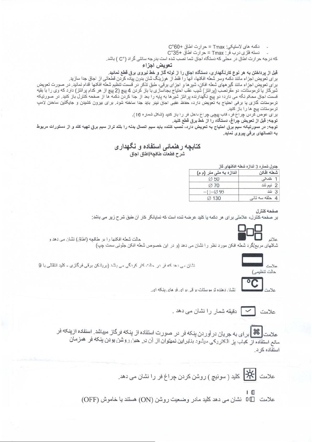

10. ﻪﻄﻘﻧ رد ﻩﺪﺷ ﺮﮐذ ماﺪﻗا ﺎﺑ ار ﯽﺋﻮﻠﺟ بﺎﻗ3ﺪﻴﻨﮐ راﻮﺱ ادﺪﺠﻣ سﻮﮑﻌﻣ ﺖﻟﺎﺣ رد ،ﯽﺋﻻﺎﺑ .
ﻦﮑﻧﺎﻳﺮﺑ ﻪﻠﻌﺷ ﻢﻴﻈﻨﺕ/ﻦﮐ خﺮﺳ:ﺪﻴﻨﮐ ماﺪﻗا ﺮﻳز تارﻮﺘﺱد ﺐﺴﺣﺮﺑ ﻞﻗاﺪﺣ ﻢﻴﻈﻨﺗ یاﺮﺑ :
ﻪﮑﻨﻳا ﺎﺗ ﺪﻴﺋﺎﻤﻧ ﺖﻗد ار ﻪﻠﻌﺷ ﺖﻈﻠﻏ قﺎﺟا خارﻮﺱ ﻖﻳﺮﻃ زا ﻪﻠﻌﺷ ﻦﺘﺷاﺪﻬﮕﻧ ﻦﻴﺣ نﺎﻣﺰﻤه رﻮﻄﺑ و ﺪﻴﻧادﺮﮕﺑ ﭗﭼ ﺎﻳ ﺖﺱار یﻮﺴﺑ ار تﺎﺱﺎﺱ
ﺪﻧﺎﻤﺑ ﻦﺷور ﺮﺜﮐاﺪﺣ ﻪﺑ ﻞﻗاﺪﺣ ﺖﻟﺎﺣ زا ﻊﻳﺮﺱ لﺎﻘﺘﻧا مﺎﮕﻨه یو.
راﺪﺸه: ﺎﻬﻧﺁ ﺎﻡا و ،دﻮﺷ مﺎﺠﻧا ﯽﻌﻴﺒﻃ زﺎﮔ یﺎﻬﻨﮑﻓا ﻪﻠﻌﺷ رد ﻂﻘﻓ ﻻﺎﺑ ﻩﺪﺷ ﺮﮐذ ﻢﻴﻈﻨﺕ ﺖﻤﺴﺑ ﺮﺧﺁ رد ﺪﻳﺎﺑ ﭻﻴﭘ ،ﻊﻳﺎﻡ زﺎﮔ ﺎﺑ ﻩدﺎﻔﺘﺳا ﻞﺑﺎﻗ ی
دﻮﺷ ﻞﻔﻗ دﺮﮕﺘﻋﺎﺳ.
راﺪﺸه: دراﺪﻧ ﻞﻗاﺪﺡ ﻢﻴﻈﻨﺕ ﻪﺑ ﯽﺟﺎﻴﺘﺡا ﻦﻳﺮﺑﺎﻨﺑ و ﺪﻨﮐ ﯽﻡ رﺎﮐ ﺮﺜﮐاﺪﺡ ﻪﺟرﺪﺑ ﻪﺸﻴﻤه ﻦﮑﻧﺎﻳﺮﺑ ﻦﮑﻓا ﻪﻠﻌﺷ ،ﻦﮑﻧﺎﻳﺮﺑ ﮏﺕ ﻦﮑﻓا ﻪﻠﻌﺷ ﺎﺑ ﯽﻟﺪﻡرد.
ﻪﺟﻮﺕ : ﻮﺷ مﺎﺠﻧا ﯽﻌﻴﺒﻃ زﺎﮔ یﺎﻬﻨﮑﻓا ﻪﻠﻌﺷ رد ﻂﻘﻓ ﻻﺎﺑ ﻩﺪﺷ ﺮﮐذ ﻢﻴﻈﻨﺕ ﺖﻤﺴﺑ ﺮﺧﺁ رد ﺪﻳﺎﺑ ﭻﻴﭘ ،ﻊﻳﺎﻡ زﺎﮔ ﺎﺑ ﻩدﺎﻔﺘﺳا ﻞﺑﺎﻗ یﺎﻬﻧﺁ مﺎﻡا و ،د
دﻮﺷ ﻞﻔﻗ دﺮﮕﺘﻋﺎﺳ .دراﺪﻧ ﻞﻗاﺪﺡ ﻢﻴﻈﻨﺕ ﻪﺑ جﺎﻴﺘﺡا ﭻﻴه ،ﻦﻳﺮﺑﺎﻨﺑ ﺪﻨﮐ ﯽﻡ رﺎﮐ ﺮﺜﮐاﺪﺡ ﺖﻟﺎﺤﺑ ﻪﺸﻴﻤه ﻦﮑﻧﺎﻳﺮﺑ ﻦﮑﻓا ﻪﻠﻌﺷ.
قﺮﺑ یوﺮﻴﻧ ﻂﺧ ﺎﺑ ﻩﺎﮕﺘﺳد ندﺮﮐ ﻞﺼﺘﻡ
ﻧاﻮﻗ و تارﺮﻘﻡ مﺎﻤﺕ ﻖﻓاﻮﻡ ﺪﻳﺎﺑ قﺮﺑ یوﺮﻴﻧ ﻂﺧ ﺎﺑ لﺎﺼﺕاﺪﺷﺎﺑ ﻢﮐﺎﺡ ﻦﻴ.
ﻪﮐ ﺪﻴﻨﮐ نﺎﻨﻴﻤﻃا ﺪﻳﺎﺑ لﺎﺼﺗا عﻮﻧ ﺮه زا ﻞﺒﻗ:
دﻮﺑ ﺪهاﻮﺨﻧ لﻮﺌﺴﻣ ﻪﺟو ﭻﻴﻬﺑ ﻩﺪﻨﻨﮐ ﺪﻴﻟﻮﺗ ﻪﻣزﻻ.
ﺪﺷﺎﺑ ﻞﺼﺘﻡ قﺮﺑ یوﺮﻴﻧ ﻂﺧ ﺎﺑ یﺰﻳﺮﭘ ﻖﻳﺮﻃ زا ﻩﺎﮕﺘﺳد ﻪﮑﻴﺕرﻮﺹ رد:
ﻧ زا ﺖﻳﺎﻋر ﺎﺑﺪﻴﻨﮐ ﻞﺼﺘﻣ ﺮﻳز تﺎﮑ:
فوﺮﺡL) ﻩﺪﻧز = (؛یا ﻩﻮﻬﻗ ﻢﻴﺳ
فوﺮﺡ
N) ﯽﻨﺜﻨﺧ = (؛ﮓﻧر ﯽﺑﺁ ﻢﻴﺳ
) ﻪﻧﺪﺑ لﺎﺼﺕا = (ﺰﺒﺳ ﻢﻴﺳ-؛درز
ﺖﻡﻼﻋ
ددﺮﮔ کﺎﻧﺮﻄﺥ نﺪﺷ غاد ﺐﺟﻮﻣ.
ﺪﺷﺎﺑ ﻞﺼﺘﻡ قﺮﺑ یوﺮﻴﻧ ﻂﺧ ﺎﺑ ﻢﻴﻘﺘﺴﻡ رﻮﻄﺑ ﻩﺎﮕﺘﺳد ﻪﮑﻴﺕرﻮﺹ رد:
ﺪﺷﺎﺑ ﺮﻳﺬﭘ نﺎﮑﻣا قﺮﺑ.
ﺰﺒﺱ ﻪﻧﺪﺑ لﺎﺼﺗا ﻢﻴﺱ ﻪﮐ ﻢﻴﻨﮐ ﯽﻣ ﻪﻴﺻﻮﺗ ًﺎ ﻳ ﻮ ﻗ ﺎﻣ- زﺎﺱرﺎﮐ ﻢﺘﺴﻴﺱ ﮏﻳﺎﺑ ار ﮓﻧر درز ﺪﻳزﺎﺱ ﻢﮑﺤﻣ ﻪﻧﺪﺑ لﺎﺼﺗا.
راﺪﺸه : ﻪﻧﺪﺑ لﺎﺼﺕا ﻢﻴﺳ ،ﻩﺪﺷ ﺾﻳﻮﻌﺕ قﺮﺑ ﻢﻴﺳ ﺮﮔا)درز-ﺰﺒﺳ ( ﺪﻳﺎﺑ قﺮﺑ ﻮﻠﺑﺎﺕ ﻪﺑ ﻪﺘﺳﻮﻴﭘ2ﺪﺷﺎﺑ ﺎﻬﻤﻴﺳ ﺮﺋﺎﺳ زا ﺮﺕ ﺪﻨﻠﺑ ﺮﺘﻡ ﯽﺘﻧﺎﺳ .
نﺎﺕ ﻩﺎﮕﺘﺳد زا ﺖﺒﻗاﺮﻡ
ﻪﺟﻮﺕ :ﻢﻬﻡ تﺎﻋﻼﻃا
ﻪﻳﺎﭘﺮﺑ ﻪﺘﻓﺮﮔ راﺮﻗ یﺎﻬﻗﺎﺟا یاﺮﺑ
ﻪﺟﻮﺗ :ﺑ ،ﻪﺘﻓﺮﮔ راﺮﻗ ﻪﻳﺎﭘﺮﺑ ﺎﻤﺷ ﻩﺎﮕﺘﺱد ﺮﮔاﺪﻴﻨﮐ ﺖﻳﺎﻋر ار طﺎﻴﺘﺣا ﻪﻳﺎﭘ یور زا شدرﻮﺥﺮﺱ زا یﺮﻴﮔﻮﻠﺟ ﺮﻃﺎﺨ.
ﯽﻗﺮﺑ ﺮﻓ ﺎﺑ ﺎﻬﻗﺎﺟا یاﺮﺑ
دﻮﺷ ﯽﻣ غاد ﻩدﺎﻔﺘﺱا نارود ﻩﺎﮕﺘﺱد .ﺪﻴﻨﮐ ﺲﻤﻟ ﺪﻳﺎﺒﻧ ار ﺮﻓ ﻞﺥاد رد ﺶﻳﺎﻣﺮﮔ ﺖﻨﻤﻟا.
ﯽﻗﺮﺑ ﺮﻓ ﺎﺑ ﺎﻬﻗﺎﺟا یاﺮﺑ
ﻪﺟﻮﺗ :ﺪﻧﻮﺷ غاد ﻩدﺎﻔﺘﺱا نارود ﺪﻨﻧاﻮﺗ ﯽﻣ ﯽﺱﺮﺘﺱد ﻞﺑﺎﻗ تﺎﻌﻄﻗ . قﺎﺟا زا ار نﺎﮐدﻮﮐﺪﻳراﺪﻬﮕﻧ رود.
ﺮﻓ یا ﻪﺸﻴﺷ یﺎﻬﺑرد یاﺮﺑ
ار ﺢﻄﺱ ﺪﻧاﻮﺗ ﯽﻣ نﺁ ﻪﮑﻧﻮﭼ ﺪﻳزرو یراد دﻮﺥ یﺰﻠﻓ ﯽﮑﺷﺎﻗ راﺰﺑا ﺎﻳ ﻩﺪﻨﻳﺎﺱ ﻦﮑﮐ ﺎﭘ تﻻﻮﺼﺤﻣ ﻩدﺎﻔﺘﺱا زا ﺮﻓ یا ﻪﺸﻴﺷ برد ندﺮﮐ ﺰﻴﻤﺗ یاﺮﺑ
ددﺮﮔ ﻪﺸﻴﺷ ﻦﺘﺴﮑﺷ ﺚﻋﺎﺑ ﻩﺪﻴﺷاﺮﺥ.
دﺮﮐ ﻩدﺎﻔﺘﺳا یﻮﺷرﺎﺨﺑ زا ﺪﻳﺎﺒﻧ قﺎﺟا ﻩﺎﮕﺘﺳد ندﺮﮐ ﺰﻴﻤﺕ یاﺮﺑ.
ﻪﺟﻮﺕ:ﻄﻗ راﺮﻗ ﻞﻣﺎﮐ ﯽﻨﻤﻳا یﺎﻬهدوﺪﺤﻣ رد ﺖﻘﻴﻘﺣ رد ﻪﮐ ﺪﺷﺎﺑ ﯽﻣ ﻻﺎﺑ رﺎﻴﺴﺑًاﺮهﺎﻇ ﻪﮐ ﺪﻨﺱر ﯽﻣ ﯽﺗراﺮﺣ ﻪﺟرﺪﺑ نﺪﺷ غاد ﺎﺑ قﺎﺟا دﺪﻌﺘﻣ تﺎﻌ
Cﺪﻨﺱﺮﺑ ﺮﻳز تراﺮﺣ ﻪﺟرﺪﺑ ﺪﻨﻧاﻮﺗ ﯽﻣ ﺮﻴﮔ ﻞﺑﺎﻗ ﯽﺗﺎﻌﻄﻗ ،ﺖﻋﺎﺱ ﮏﻳ یاﺮﺑ :
ﺪﻧراد .ﺎﻬﺘﻳدوﺪﺤﻣ ﻦﻳا ﻖﺑﺎﻄﻣ:
- لﺮﺘﻨﮐ ﻪﺤﻔﺻ :Tmax = قﺎﻃا تراﺮﺣ+60°C
- ﺮﻓ برد ﻪﺸﻴﺷ :Tmax = قﺎﻃا تراﺮﺣ+60°C
- ﺮﻓ برد یﺰﻠﻓ ﺖﻤﺴﻗ :Tmax = قﺎﻃا تراﺮﺣ+45°C
) 1 ﻪﻤﮐد ﻦﺘﺷاﺪﻬﮕﻧﺎﺑ ار ﻦﮑﻓا ﻪﻠﻌﺷﺪﻴﻨﮐ ﻦﺷور ﺮﺜﮐاﺪﺣ ﺖﻟﺎﺤﺑ.
)2 ﻞﻗاﺪﺣ یاﺮﺑ ﻪﺘﺴﺑ ار ﺮﻓ برد10ﺪﻳراﺪﻬﮕﻧ ﻦﺷور ﻪﻘﻴﻗد .
)3 ﻞﻗاﺪﺣ ﺖﻟﺎﺤﺑ ار ﻪﻤﮐد)ﮏﭼﻮﮐ ﻪﻠﻌﺷ (ﺪﻳزﺎﺱاﺪﺟ ًا ﺪ ﻌ ﺑ و ﺪﻴﻨﮐ ﻢﻴﻈﻨﺗ.
)4 پﺎﭘﻮﺱ ﻪﻧﺪﺑ ﺮﺑ ار راﺪﮐﺎﭼ ﮏﭼﻮﮐ ﯽﺘﺸﮑﭽﻴﭘ ﮏﻳ ،ﺪﺷﺎﺑ ﯽﻣ ﺰﻬﺠﻣ ﯽﻨﻤﻳا یﺎﻬﭘﺎﭘﻮﺱ ﺎﺑ قﺎﺟا) ﻩرﺎﻤﺷ ﻞﮑﺷ13 دﻮﺷ ﻊﺟاﺮﻣ ( ﻩدﺮﺑ رﺎﮑﺑ ﭻﻴﭘ
• ﻪﺷﺎﺑ ﻩﺎﮕﺘﺱد ﺮﺜﮐاﺪﺣ ﯽﻣﺎﻧ ﺖﻴﻓﺮﻇ ﺐﺱﺎﻨﻣ ﺎهﺰﻳﺮﭘ و ﯽﺸﮑﻤﻴﺱ)ﺪﻴﻨﮐ ﻊﺟاﺮﻣ قﺎﺟا ﻪﻧﺪﺑ ﯽﻨﻴﺋﺎﭘ ﺖﻤﺴﻗ رد لﺎﻳﺮﺱ کﻼﭘ ﻪﺑ.(
• ﺪﺷﺎﺑ ﺮﺙﻮﻣو ﻪﻧﺪﺑ لﺎﻬﺼﺗا یاراد ﻢﮐﺎﺣ تارﺮﻘﻣو ﻦﻴﻧاﻮﻗ ﺐﺴﺣﺮﺑ ﺐﺱﺎﻨﻣ رﻮﻄﺑ ﯽﺸﮑﻤﻴﺱ ﺎﻳ ﺰﻳﺮﭘ . ﻋ عﻮﻧ ﺮه یاﺮﺑ تارﺮﻘﻣ زا ﺖﻳﺎﻋر مﺪ
• ﺪﺷﺎﺑ لﺎﻳﺮﺱ ﻩرﺎﻤﺷ کﻼﭘﺮﺑ ﻩﺪﺷ ﺮﮐذ ﯽﻣﺎﻧ ﺖﻴﻓﺮﻇ ﺐﺱﺎﻨﻣ یدﺎﻋ ﺶﻴﻓ ﮏﻳ یاراد ﻢﻴﺱ ﻪﮐ ﺪﻴﻨﮐ نﺎﻨﻴﻤﻃا ﺪﻳﺎﺑ . ﻩرﺎﻤﺷ ﻞﮑﺷ ﻖﺑﺎﻄﻣ ارﺎﻬﻤﻴﺱ15
• تراﺮﺣ ﻪﺟرد زا نﺁ ﺖﻤﺴﻗ ﭻﻴه ﻪﮐ دﺮﻴﮔ راﺮﻗ ﯽﺘﻟﺎﺤﺑ قﺮﺑ ﻢﻴﺱ75 Kﺪﻨﮑﻧ زوﺎﺠﺗ .
• ﻣراﺪﻣ ﺎﻳ ﺎﻬهﺪﻨهﺎﮐ ،ﺎهرﻮﺘﭘادﺁ ندﺮﮐ ﻩدﺎﻔﺘﺱا زا لﺎﺼﺗا یاﺮﺑ و ﯽﻋﻮﻨﺼﻣ یﺎﻬﻟﺎﺼﺗا ﺚﻋﺎﺑ ﺪﻨﻧاﻮﺗ ﯽﻣ ﺎﻬﻧﺁ ﻪﮑﻧﻮﭼ ﺪﻳزرو یراددﻮﺥ قﺮﺑ یزاﻮ
• ﻪﺟرد ﻂﻳاﺮﺷ ﺖﺤﺗ ﻪﮐ ،ﺪﺷﺎﺑ ﻪﺘﺷاد دﻮﺟو قﺮﺑ ﻊﺒﻨﻣ زا ﻩﺎﮕﺘﺱد ﻊﻄﻗ یاﺮﺑ یا ﻪﻠﻴﺱو ﺪﻴﻨﮐ نﺎﻨﻴﻤﻃاIIIﺱﺎﻨﻣ ﻪﻠﺻﺎﻔﺑ ژﺎﺘﻟو ﻞﻣﺎﮐ ﻊﻄﻗ یاﺮﺑ زﺎﺑ ﺐ
• ﺪﺷﺎﺑ ﻪﺘﺷاد یا ﻊﻧﺎﻣ ﭻﺋﻮﺱ ﻖﻳﺮﻃ زا ﺪﻳﺎﺒﻧ ﻪﻧﺪﺑ لﺎﺼﺗا ﻢﻴﺱ.
• دﺮﺑ رﺎﮑﺑ ﯽﻗﺮﺑ لﺎﺼﺗا ﻆﻔﺣ یاﺮﺑ ناﻮﺗ ﯽﻣ ار قﺮﺑ نﺎﻳﺮﺟ ﻪﻓﺮﻃ ﮏﻳ سﺎﺴﺣ قﻮﻓ ﻪﻠﻴﺱو ﮏﻳ ًﺎﺑوﺎﻨﺘﻣ.
)1 تراﺮﺣ ﻪﺟرﺪﺑ ﺮﻓ ﺎﺑ200°Cﺰﻳر تراﺮﺣ تﺎﺟرد ﻪﺑ ﺪﻨﻧاﻮﺗ ﯽﻣ ﺪﻨﺷﺎﺒﻧ ﺮﻴﮔ ﻞﺑﺎﻗ ﻪﮐ ﯽﺋﻮﻠﺟ ﯽﺱﺮﺘﺱد ﻞﺑﺎﻗ تﺎﻌﻄﻗ ،ﺖﻋﺎﺱ ﮏﻳ یاﺮﺑ ﺪﻨﺱﺮﺑ :
)2 تراﺮﺣ ﻪﺟرﺪﺑ ﺮﻓ ﺎﺑ230°

یرﻮﺻ نﺎﻳﺮﺟ ناﺰﻴﻣ لزﺎﻧ ﺮﻄﻗ رﺎﺸﻓ زﺎﮔ عﻮﻧ ﻦﮑﻓا ﻪﻠﻌﺷ
kcal/h kw l/h g/h 1/100 ﺮﺘﻣ ﯽﻠﻣ mbar
860 1 95 - 72 20
860 1 - 73 50 30
860 1 - 71 50 37
1505 1,75 167 - 97 20
1505 1,75 - 127 65 30
1505 1,75 - 125 65 37
2580 3 286 - 115 20
2580 3 - 218 85 30
2580 3 - 214 85 37
2494 2,9 276 - 120 20
2494 2,9 - 211 85 30
2494 2,9 - 207 85 37
3010 3,5 334 - 131 20
3010 3,5 - 254 95 30
3010 3,5 - 250 95 37
3182 3,7 352 - 135 20
3182 3,7 - 269 90 30
3182 3,7 - 264 90 37
1720 2 191 - 115 20
1720 2 - 145 68 30
1720 2 - 143 68 37
ﯽﻗﺮﺑ ﻦﮑﻧﺎﻳﺮﺑ و یزﺎﮔﺮﻓ ﺎﻳ ،ﮏﺕ لﺮﺘﻨﮐ ﺎﺑ ﻩاﺮﻤه یزﺎﮔ ﻦﮑﻧﺎﻳﺮﺑو یزﺎﮔﺮﻓ ﺎﺑ لﺪﻡ(
3870 4,5 429 - 150 20
3870 4,5 - 327 90 30
3870 4,5 - 321 90 37
1720 2 191 - 115 20
1720 2 - 145 68 30
1720 2 - 143 68 37
ﺎﻬﻨﮑﻓا ﻪﻠﻌﺷ ﻢﻴﻈﻨﺕ
دراد دﻮﺟو ﺮﻴﺷ ﻪﻧﺪﺑ ﺮﺑ ﻪﮑﻠﺑ ﺪﺷﺎﺑ ﯽﻤﻧ دﻮﺟﻮﻣ ﻪﻠﻴﻣ خارﻮﺱ ﺮﺑ تﺎﺱﺎﺱ) ﻩرﺎﻤﺷ ﻞﮑﺷ13.(
ﯽﻌﻴﺒﻃ زﺎﮔ G20
نﺎﺗﻮﺑ G30 ﯽﮑﻤﮐ
نﺎﭘوﺮﭘG31
ﯽﻌﻴﺒﻃ زﺎﮔ G20
نﺎﺗﻮﺑ G30 ﺪﻨﺗ ﻢﻴﻧ
نﺎﭘوﺮﭘG31
ﯽﻌﻴﺒﻃ زﺎﮔ G20
نﺎﺗﻮﺑ G30 ﺪﻨﺗ
نﺎﭘوﺮﭘG31
ﯽﻌﻴﺒﻃ زﺎﮔ G20
نﺎﺗﻮﺑ G30 ﺰﭘ ﯽهﺎﻣ ﻪﻠﻌﺷ
نﺎﭘوﺮﭘG31
ﯽﻌﻴﺒﻃ زﺎﮔ G20 قﻮﻓ
نﺎﺗﻮﺑ G30 ﺪﻨﺗ
ﭘ نﺎﭘوﺮG31
)ﻞﺑود یﺎﻬﻟﺮﺘﻨﮐﺎﺑ یزﺎﮔ ﻦﮑﻧﺎﻳﺮﺑ و یزﺎﮔ ﺮﻓ ﺎﺑ لﺪﻡ(
ﯽﻌﻴﺒﻃ زﺎﮔ G20
نﺎﺗﻮﺑ G30 ﺮﻓ
نﺎﭘوﺮﭘG31
ﯽﻌﻴﺒﻃ زﺎﮔ G20
نﺎﺗﻮﺑ G30 ﻦﮑﻧﺎﻳﺮﺑ
نﺎﭘوﺮﭘG31
ﯽﻌﻴﺒﻃ زﺎﮔ G20
نﺎﺗﻮﺑ G30 ﺮﻓ
نﺎﭘوﺮﭘG31
ﯽﻌﻴﺒﻃ زﺎﮔ G20
نﺎﺗﻮﺑ G30 ﻦﮑﻧﺎﻳﺮﺑ
نﺎﭘوﺮﭘG31
قﺎﺟا ﻪﭽﻗﺎﻃ ﻦﮑﻓا ﻪﻠﻌﺷ ﻢﻴﻈﻨﺕ:ﺪﻴﺋﺎﻤﻧ ماﺪﻗا ﺮﻳز رﻮﺘﺱد ﺐﺴﺣ ﺮﺑ ﻪﭽﻗﺎﻃ یﺎﻬﻨﮑﻓا ﻪﻠﻌﺷ ﻞﻗاﺪﺣ ﻢﻴﻈﻨﺗ یاﺮﺑ :
ﺮﻓ ﻦﮑﻓا ﻪﻠﻌﺷ ﻢﻴﻈﻨﺕ:ﻳز یﺎهرﻮﺘﺱد ﻖﺒﻃ ﺎﻬﻨﮑﻓا ﻪﻠﻌﺷ ﻞﻗاﺪﺣ ﻢﻴﻈﻨﺗ ﺮﻃﺎﺨﺑ ﺪﻴﺋﺎﻤﻧ ماﺪﻗا ﺮ.
ﻩرﺎﻤﺷ لوﺪﺟ1
ﻢﻴﻈﻨﺕ"ﻞﻗاﺪﺡ "ﺎﻬﻨﮑﻓا ﻪﻠﻌﺷ:
1. ﻞﻗاﺪﺣ ﻪﺟرد ﻪﺑ ﻢﻴﻈﻨﺗ ﺎﺑ ار ﻦﮑﻓا ﻪﻠﻌﺷ)ﮏﭼﻮﮐ ﻪﻠﻌﺷ (ﮐ ﻦﺷورﺪﻴﻨ.
2. ﺪﻴﻧادﺮﮕﺑ ﻪﻠﻴﻣ ﺮﺑ ﯽﻟﻮﻤﻌﻣ رﺎﺸﻓ ﺎﺑ ار ﺮﻴﺷ ﻪﻤﮐد.
3. ﺮﻴﺷ ﻪﻠﻴﻣ رد ار راﺪﮐﺎﭼ ﯽﺘﺸﮐ ﭻﻴﭘ ﮏﻳ ،ﺪﺷﺎﺑ ﻪﺘﺷاﺪﻧ ﻪﭽﻗﺎﻃا یﺎﻬﻨﮑﻓا ﻪﻠﻌﺷ یور ﺮﺑ ﯽﻨﻤﻳا یﺎه پﺎﭘﻮﺱ قﺎﺟا ﻪﮑﻴﺗرﻮﺻ رد) ﻩرﺎﻤﺷ ﻞﮑﺷ12
( ﺮﮔا ؛ﺪﺱﺮﺑ ﻞﻗاﺪﺣ ﺖﻟﺎﺣ ﻪﺑ ﻪﻠﻌﺷ ﻪﮑﻨﻳا ﺎﺗ ﺪﻨﻳادﺮﮕﺑ ﭗﭼ ﺎﻳ ﺖﺱار ﺖﻤﺴﺑ تﺎﺱ ﺎﺱ ﭻﻴﭘ و ﺪﻴﻨﮐ ﻞﺥاد ﭻﻴﭘ ،ﺪﺷﺎﺑ ﯽﻨﻤﻳا یﺎﻬﭘﺎﭘﻮﺱ یاراد قﺎﺟا
4. ﻪﺑ ﺮﺜﮐاﺪﺣ زا ﻪﺟرد ﻊﻳﺮﺱ لﺎﻘﺘﻧا مﺎﮕﻨه ﻪﮐ ﺪﻴﻨﮐ نﺎﻨﻴﻤﻃاﻞﻗاﺪﺣدﻮﺸﻧ شﻮﻣﺎﺥ ﻪﻠﻌﺷ ،.
1. ﺪﻳزﺎﺱ ﻊﻄﻗ تﻻﺎﺼﺗا زا ار ﻩﺎﮕﺘﺱد ﺎﻬﻤﻴﻈﻨﺗ عﻮﻧ ﺮه مﺎﺠﻧا زا ﻞﺒﻗ
2. ﺪﻴﻨﮐ اﺪﺟ ار ﺎه ﻪﻤﮐد
3. ﺪﻳزﺎﺱ اﺪﺟ بﺎﻗ ﻒﮐ زا ﺎﻬﭽﻴﭘ ندﺮﮐزﺎﺑ ﺎﺑ ار لﺮﺘﻨﮐ بﺎﻗ
4. ﺪﻳزﺎﺱ ﻞﺥاد ار تﺎﺘﺱﻮﻣﺮﺗ ﻪﻤﮐد
5. یﺪﻴﻨﮐ ﻦﺷور ﺮﺜﮐاﺪﺣ ﺖﻟﺎﺤﺑ ﻪﻤﮐد ندﺮﮐ ﻢﻴﻈﻨﺗﺎﺑ ار ﻦﮑﻓا ﻪﻠﻌﺷ) .ور ﺖﺱد ﺎﺑ ناﻮﺗ ﯽﻣ ﺖﻳﺮﺒﮐﺎﺑدﺮﮐ ﻦﺷ.(
6. یﺮﺑ ﻞﻗاﺪﺣ ار ﺮﻓ و ﺪﻳﺪﻨﺒﺑ ار ﺮﻓ برد10ﺪﻳراد ﻪﮕﻧ ﻦﺷور ﻪﻘﻴﻗد .
7. ﺖﻟﺎﺤﺑ ار ﻪﻤﮐدﻞﻗاﺪﺣ )120°(ﺪﻴﺸﮐ نوﺮﻴﺑ اﺮﻧﺁ ﻩدﺮﮐ ﻢﻴﻈﻨﺗ .
8. تﺎﺱﺎﺱ ﭻﻴﭘ ﺮﺑ ار راﺪﮐﺎﭼ ﯽﺘﺸﮑﭽﻴﭘ ﮏﻳ) ﻩرﺎﻤﺷ ﻞﮑﺷ14 (نﺎﻣﺰﻤه رﻮﻄﺑو ﺪﻳﺮﺒﺑ رﺎﮑﺑ
9. ﻪﻧزور ﻖﻳﺮﻃ زا ﻪﻠﻌﺷ ﻦﺘﺷاﺪﻬﮕﻧ ﻦﻴﺣ)خارﻮﺱ ( ار ﻪﻠﻌﺷ ﺖﻈﻠﻏ ،قﺎﺟا ﻦﺷور ﺮﺜﮐاﺪﺣ ﻪﺑ ﻞﻗاﺪﺣ ﺖﻟﺎﺣ زا ﻊﻳﺮﺱ لﺎﻘﺘﻧا ﻦﻴﺣ ﻪﮑﻨﻳا ﺎﺗ ﺪﻴﻨﮐ ﺖﻗد
ﺪﻧﺎﻤﺑ.

ﺪﻗ ﻢﻴﻈﻨﺕ یﺎه ﻪﻳﺎﭘ) ﻩرﺎﻤﺷ ﻞﮑﺷ1(
ﺪﻧا ﻩﺪﺷ یﺪﻨﺑ ﻪﺘﺴﺑ ﯽﺋﻻﺎﺑ ﻪﺒﻌﺟ رد ﺎه ﻪﻳﺎﭘ.
ه ﻪﻳﺎﭘﺪﻨﺷﺎﺑ ﯽﻤﻧ ﺶﺨﺑ نﺎﻨﻴﻤﻃا یدﺎﻳز یﺎه ﻪﻠﺻﺎﻓ ﻪﺑ قﺎﺟا لﺎﻘﺘﻧا یاﺮﺑ ﺎه ﻪﻳﺎﭘ ؛ﺪﻧﻮﺷ ﻩداد ﺎﺟ قﺎﺟا ﯽﺋﺎﻬﻧ ﺐﺼﻧ ﺖﻟﺎﺣ رد ﺪﻳﺎﺑ ﺎ.
ﺪﻧﺮﻴﮔﺎﺟ ﺢﻴﺤﺻ رﻮﻄﺑ ﻒﮐ رد قﺎﺟا یﺎه ﻪﻳﺎﭘ ﻪﮑﻨﻳا ﺎﺗ ﺪﻴﻨﮐ ﺪﻨﻠﺑ دﻮﺥ یﺎﭘ ﺎﺑ ار نﺁ ،قﺎﺟا یﺪﻨﺑ ﻪﺘﺴﺑ ندﺮﮐ زﺎﺑ زا ﺪﻌﺑ . ﺎﺗ ﺪﻳرﺁ ﻦﻴﺋﺎﭘ ﻪﺘﺱﺁ ار قﺎﺟا
ﺶﻧزو ﻪﮑﻨﻳادﺮﻴﮔﺎﺟ ﻪﻋﻮﻤﺠﻣ ﻦﻣﺎﺿ یﺎه ﻪﻳﺎﭘﺮﺑ .دﻮﺷ ﻩدﺮﺑ رﺎﮑﺑ یا ﻪﻠﻴﻣ ﺎﻳ ﻦﮐ ﺪﻨﻠﺑ راﺰﺑا ﻪﮐ دﻮﺸﻴﻣ ﻪﻴﺻﻮﺗ قﺎﺟا ندﺮﮐ ﺞﮐ یﺎﺠﺑ.
قﺎﺟا ﻦﻡاد ﺐﺼﻧ) ﺪﺷﺎﺑ ﯽﻡ دﻮﺟﻮﻡ صﻮﺼﺨﺑ یﺎﻬﻟﺪﻡ رد ﻂﻘﻓ(
ﻞﮑﺷ رد ﻩﺪﺷ ﻩداد نﺎﺸﻧ ﻖﺑﺎﻄﻣ ار قﺎﺟا ﻦﻣاد ﺎه ،ﻪﻳﺎﭘ ﺐﺼﻧ زا ﺪﻌﺑ2.2ﺪﻴﻨﮐ ﺐﺼﻧ .
ﻢﺋﺎﻗ ﻩﺮﺠﻨﭘ ﺐﺼﻧ
ﻢﺋﺎﻗ ﻩﺮﺠﻨﭘ ﺎﺑ ﻩﺪﺷ ﻪﻴﻬﺗ یﺎه ﭻﻴﭘﺎﺑ ار ﻒﮐ و ﺪﻳراﺬﮕﺑﺎﺟﺮﺑ ار ﻢﺋﺎﻗ ﻩﺮﺠﻨﭘ) ﻞﮑﺷ3 (ﺪﻴﭽﻴﭙﺑ ﻢﮑﺤﻣ.
ﺗ یﺎﻬﭽﻴﭘ زا ﻩدﺎﻔﺘﺱا ﺎﺑ ار ﻢﺋﺎﻗ ﻩﺮﺠﻨﭘ ﻂﺱوﻬﻴ ﻢﺋﺎﻗ ﻪﻳﺎﭘ ﺎﺑ ﻩﺪﺷ ﻪ) ﻞﮑﺷ3 (ﺪﻳﺪﻨﺒﺑ ﻢﮑﺤﻣ.
ﺮﻓ ﻪﺘﺳد و ﺐﻘﻋ ﻩدﺮﻧ ﺐﺼﻧ
ﻪﺘﺱد و ﻩدﺮﻧﺖﺱا ﻩﺪﺷ یﺪﻨﺑ ﻪﺘﺴﺑ ﻢﺋﺎﻗ ﻩﺮﺠﻨﭘ ﺎﺑ ﻩاﺮﻤه .
ﺖﺱا ﻩﺪﺷ ﻢهاﺮﻓ ﯽﺻﻮﺼﺨﺑ ﻲﺋﺎﻬﻟﺪﻣ ﺎﺑ ﻩاﺮﻤه ﻂﻘﻓ ﻩدﺮﻧ.
A – 4B- 4Cﺪﻴﻨﮐ ژﺎﺘﻨﻣ
یﺎﻬﻠﮑﺷ رد ﻩﺪﺷ ﻩداد نﺎﺸﻧ ﻖﺒﻃ ار ﺮﻓ ﻪﺘﺱد و قﺎﺟا ﻩدﺮﻧ4
نﺪﺷ نﻮﮔژاو زا یﺮﻴﮔﻮﻠﺟ یاﺮﺑ ﻢﺘﺴﻴﺳ ﺐﺼﻧ
ﺪﻳﺎﺑ ﻩﺪﺷ ﻪﻴﻬﺗ ﻢﺘﺴﻴﺱ ،ﯽﻓدﺎﺼﺗ نﺪﺷ نﻮﮔژاو زا یﺮﻴﮔﻮﻠﺟ ﺮﻃﺎﺨﺑدﻮﺷ ﺐﺼﻧ . یﺎﻬﻠﮑﺷ رد ﻩﺪﺷ ﻩداد نﺎﺸﻧ ﺐﺴﺣﺮﺑ ار ﻢﺘﺴﻴﺱ5–5Aﺪﻴﻨﮐ ﺐﺼﻧ .
زﺎﮔ ﯽﺸﮐ ﻪﻟﻮﻟ ﺎﺑ ﻩﺎﮕﺘﺳد ندﺮﮐ ﻞﺼﺘﻡ
ﺎﺑ ﺮﻓ ﺐﻘﻋرد ﺎﻳو ﻦﮑﻡﺮﮔ ﯽﺋﻮﺸﮐ ﻞﺧاد ﺐﺼﻧ کﻼﭘ ﺮﺑ ﻩﺪﺷ جرد تﺎﺼﺨﺸﻡ ﻪﮐ ﺪﻴﻨﮐ نﺎﻨﻴﻤﻃا ،زﺎﮔ ﯽﺸﮐ ﻪﻟﻮﻟﺎﺑ ﻩﺎﮕﺘﺳد ندﺮﮐ ﻞﺼﺘﻡ زا ﻞﺒﻗ
ﺪﺷﺎﺑ ﻪﺘﺷاد ﺖﻘﺑﺎﻄﻡ زﺎﮔ ﯽﺸﮐ ﻪﻟﻮﻟ تﺎﺼﺨﺸﻡ.
چﺮﺑ ﻩﺎﮕﺘﺳد ﻦﮑﻡﺮﮔ یﻮﺸﮐ ﻞﺧاد رد و ﻪﭽﺑﺎﺘﮐ ﻦﻳا ﺮﺧﺁ ﻪﺤﻔﺹ رد ﯽﭙﺴ) ﺐﻘﻋ ﺖﻤﺴﻘﺑ ﺎﻳ ( ﯽﻡ ﻢهاﺮﻓ ار ﻩﺎﮕﺘﺳد ندﺮﮐ ﻢﻴﻈﻨﺕ ﻪﺑ ﻊﺟار ﯽﺕﺎﻋﻼﻃا
ﺪﻨﮐ :یزاﺪﻧا ﻩار رﺎﺸﻓ و زﺎﮔ عﻮﻧ.
ﻢﻬﻡ ﻪﺟﻮﺕ:دﺎﻔﺘﺳا بﻮﺧ راد اﻮه قﺎﻃا ﮏﻳ رد ﻂﻘﻓ ﺪﻳﺎﺑ و دﻮﺷ ﺐﺼﻧ یرﺎﺟ ﻢﮐﺎﺡ ﯽﻠﻡ یﺎهدراﺪﻧﺎﺘﺳا ﺐﺴﺡﺮﺑ ﻪﻳﺎﺑ ﻩﺎﮕﺘﺳد ﻦﻳا دﻮﺷ ﻩ.
ﻪﺟﻮﺕ: ﻩوزر ﮏﻳ یراد ﻩﺎﮕﺘﺳد زﺎﮔ ﻩرﻮﺳ ﺎﻡ ﻩﺮﻬﻡ ½یﺎهدراﺪﻧﺎﺘﺳا ﺐﺴﺡﺮﺑ ﻪﮐ ﺪﺷﺎﺑ ﯽﻡ یزﺎﮔ ﺮﻧ یرﺪﻨﻠﺳ UNI-ISO 228-1 ﺪﺷﺎﺑ ﯽﻡ.
ﯽﮑﺘﻴﺳﻻ ﮓﻨﻠﺷ ﮏﻳ زا ﻩدﺎﻔﺘﺳا ﺎﺑ زﺎﮔ ﯽﺸﮐ ﻪﻟﻮﻟ ﺎﺑ ﻩﺎﮕﺘﺳد ندﺮﮐ ﻞﺼﺘﻡ یاﺮﺑ جﺎﻴﺘﺡا درﻮﻡ ﯽﮑﻴﺘﺳﻻ ﯽﻓﺎﺿا یا ﻩرﻮﺳ ﺎﻡ ﻩﺮﻬﻡ ﮏﻳ ،راد ﺶﺸﮐ
UNI 7141دراد ﺖﻘﺑﺎﻄﻡ .
زﺎﮔ ﻒﻠﺘﺨﻡ عاﻮﻧا یاﺮﺑ ﻢﻴﻈﻨﺕ
ﺪﻴﺋﺎﻤﻧ ﻊﻄﻗ ﯽﻗﺮﺑ تﻻﺎﺼﺕا و زﺎﮔ ﯽﺸﮐ ﻪﻟﻮﻟ زا ار ﻩﺎﮕﺘﺳد ،یﺮﻴﻤﻌﺕ و یراﺪﻬﮕﻧ رﺎﮐ عﻮﻧ ﺮه مﺎﺠﻧا زا ﻞﺒﻗ
یﺮﮕﻳد زﺎﮔ عﻮﻧ ﺎﺑ یزاﺪﻧا ﻩار یاﺮﺑ ﺎﻬﻟزﺎﻧ ﯽﻨﻳﺬﮕﻳﺎﺟ:
ﺎﻬﻟزﺎﻧ ندﺮﮐ ضﻮﻋ یاﺮﺑﺪﻴﺋﺎﻤﻧ ماﺪﻗا ﺮﻳز ﻖﺒﻃ قﺎﺟا ﺐﻘﻋ یﺎﻬﻨﮑﻓا ﻪﻠﻌﺷ ی:
ﻩرﺎﻤﺷ8 ( ﻩرﺎﻤﺷ لوﺪﺟ رد ﻩﺪﺷ ﻩداد نﺎﺸﻧ ﻖﺒﻃ1ﺪﻳزﺎﺱ ﻦﻳﺬﮔﺎﺟ .
ﺪﻴﺋﺎﻤﻧ ماﺪﻗا ﺮﻳز ﻖﺒﻃﺮﺑ ﻦﮑﻓا ﻪﻠﻌﺷ لزﺎﻧ ندﺮﮐ ضﻮﻋ یاﺮﺑ:
دﻮﺸﻧ ﻩﺪﻴﻧﺎﺱر.
یا ﻪﻟﻮﻟ7ﺪﻴﻨﮐ ﻩدﺎﻔﺘﺱا ار یﺮﺘﻣ ﯽﻠﻣ .
ﺪﻴﺋﺎﻤﻧ ماﺪﻗا ﺮﻳز ﻖﺒﻃ ﻦﮑﻧﺎﻳﺮﺑ ﻦﮑﻓا ﻪﻠﻌﺷ لزﺎﻧ ندﺮﮐ ضﻮﻋ یاﺮﺑ:
11(
یا ﻪﻟﻮﻟ7ﺪﻴﻨﮐ ﻩدﺎﻔﺘﺱا ار یﺮﺘﻣ ﯽﻠﻣ .
ﻪﺟﻮﺕ : دزﺎﺳ رﻮﻬﻤﻡ ار ﯽﻤﻴﻈﻨﺕ ﺶﻴﭘ و ﯽﻤﻴﻈﻨﺕ ﻪﻠﻴﺳو عﻮﻧ ﺮه ،ﺪﻨﮐ ﻢﻴﻈﻨﺕ ﺪﻳز ﺮﮐﺬﺕ ﻖﺒﻃ ار ﺎﻬﻨﮑﻓا ﻪﻠﻌﺷﺪﻳﺎﺑ ﻩﺪﻨﻨﮐ ﺐﺼﻧ ،ﺎﻬﻟزﺎﻧ ﺾﻳﻮﻌﺕ زا ﺪﻌﺑ
ﺪﺷﺎﺑ ﯽﻡ دﻮﺟﻮﻡ ﯽﮐﺪﻳ یﺎﻬﻟزﺎﻧ ﺎﺑ ﻩاﺮﻤه ﻪﺴﻴﮐ ﻞﺧاد رد ﻮﻧ ﭗﺴچﺮﺑ ﻦﻳا.
2ا ﻦﻣﺎﺿ ﭻﻴﭘ ﺖﺸﭘ رد قﺎﺟ) ﻩرﺎﻤﺷ ﻞﮑﺷ رد ﻩﺪﺷ ﻩداد نﺎﺸﻧ3 (ﺪﻴﻨﮐ زﺎﺑ
) ﻩرﺎﻤﺷ ﻞﮑﺷ6 ( دراﺪﻧﺎﺘﺳا ﺎﺑ ﻪﮐ ﺖﺳا ﻩﺪﺷ ﻢهاﺮﻓ ﻩﺎﮕﺘﺳد ﺎﺑ
1. ﺪﻴﺷﺎﺑ ﻪﺘﺷاﺪﻧ ﯽﮕﺘﻓﺮﮔ قﺮﺑ ﺮﻄﺥﺎﺗ ﺪﻴﻨﮐ ﻊﻄﻗ ﯽﻠﺻا تﻻﺎﺼﺗا زا ار ﻩﺎﮕﺘﺱد.
2. ﺪﻳزﺎﺱا ﺪﺟ قﺎﺟا ﺐﻘﻋ زا ار ﯽﻨﻴﺱ یﺎه ﻦﻣﺎﺿ) ﻩرﺎﻤﺷ ﻞﮑﺷ7.(
3. ﺪﻳزﺎﺱ اﺪﺟ ار ﻦﮑﻓا ﻪﻠﻌﺷ یﺎهﺮﺱ) ﻩرﺎﻤﺷ ﻞﮑﺷ7.(
4. ﻪﻟﻮﻟ یا ﻪﺷﻮﮔ ﺶﺷ رﺎﭼﺁ ﺎﻬﻨﮑﻓا ﻪﻠﻌﺷ ندﺮﮐ ﻞﺷ یاﺮﺑ یا7 ﻮﻧ ﻢﺴﻗ زﺎﮔ رﻮﺥرد ﺐﺱﺎﻨﻣ عﻮﻧ ﺎﺑ ار ﺎﻬﻧﺁ و ﺪﻴﻨﮐ ﻩدﺎﻔﺘﺱا ار یﺮﺘﻣ ﯽﻠﻣ ) ﻞﮑﺷ
1. یﺎﻬﭽﻴﭘ ندﺮﮐ اﺪﺟ ﺎﺑ ار قﺎﺟا قﺎﻃاG) ﻩرﺎﻤﺷ ﻞﮑﺷ9 (ﺖﻤﺴﻗ ًا ﺪ ﻌ ﺑ و ،ﺪﻳزﺎﺱ اﺪﺟﺪﻳرﺁ رد ار ﺐﻘﻋ .
2. ﭻﻴﭘV ﯽﮑﺒﻠﻌﻧ زا ار ﻦﮑﻓا ﻪﻠﻌﺷ ﻩدﺮﮐ ﻞﺷار )ﮓﻨﻳزﻮه ( ﻞﭘﻮﮐﻮﻣﺮﺗ و نز ﻪﻗﺮﺠﺑ ﻪﮑﻨﻳا زا ﺖﺒﻗاﺮﻣ ﺎﺑ ،ﺪﻳزﺎﺱ اﺪﺟ) ﻩرﺎﻤﺷ ﻞﮑﺷ10 ( یرﺮﺿ
3. لزﺎﻧ ﻦﺘﺥﺎﺱ ﻦﻳﺬﮕﻳﺎﺟ یاﺮﺑR ﻩرﺎﻤﺷ لوﺪﺟ رد ﻩﺪﺷ ﻩداد نﺎﺸﻧ ﻖﺒﻃ ﺪﻳﺪﺟ زﺎﮔ عﻮﻧ یاﺮﺑ ﺐﺱﺎﻨﻣ لزﺎﻧ ﮏﻳ ﺎﺑ 1 ﮏﻳ ،ﺁ ﻩﺎﮕﺘﺱد ﻪﺷﻮﮔ ﺶﺷ رﺎﭼ
1. ﺪﻳزﺎﺱ اﺪﺟ نﺁ ﮓﻨﻳزﻮه زا ار ﻦﮑﻓا ﻪﻠﻌﺷ ﻪﺘﺥﺎﺱ ﻞﺷار ﻦﮑﻧﺎﻳﺮﺑ ﭻﻴﭘ . ﺪﻨﻨﻴﺑ ﻪﻧ یزﺮﺻ ﻞﭘﻮﮐﻮﻣﺮﺗو نز ﻪﻗﺮﺟ ﻪﮐ ﺪﻴﺷﺎﺑ ﺐﻗاﺮﻣ ﺎﻣا)ﻩرﺎﻤﺷ ﻞﮑﺷ
2. لزﺎﻧ ﻦﺘﺥﺎﺱ ﻦﻳﺬﮕﻳﺎﺟ یاﺮﺑR ﻩرﺎﻤﺷ لوﺪﺟ رد ﻩﺪﺷ ﻩداد نﺎﺸﻧ ﻖﺒﻃ ﺪﻳﺪﺟ زﺎﮔ عﻮﻧ یاﺮﺑ ﺐﺱﺎﻨﻣ لزﺎﻧ ﮏﻳ ﺎﺑ 1 . ﻪﺷﻮﮔ ﺶﺷ رﺎﭼﺁ ﻩﺎﮕﺘﺱد
وﺪﻨﮐ قﺎﺼﻟا ﻩدﻮﺟﻮﻡ ﯽﻨﻳﺬﮕﻳﺎﺠﺑ ار زﺎﮔ ﻢﻴﻈﻨﺕ ﺪﻳﺪﺟ ﭗﺴچ ﺮﺑ ﮏﻳ .

TM95C61X 40297203
TM95C31X 40297202
 Loading...