


TASC-6100
LIQUID/GRANULAR
APPLICATION CONTROL SYSTEM
USER GUIDE
PN - 98-05018
R2
Software Version 1.30
CE & STANDARD VERSION
TASC-6100
Rate Controller
® |
ON |
OPERATE |
INC. |
MID-TECH |
|
|
|
MPH |
OFF |
SETUP |
DEC. |
MIDWEST TECHNOLOGIES, INC. |
Product Vol. |
%Rate |
Appl. Rate |
|
|||||
|
|
|
||||||
Fan RPM |
|
|
Total Applied |
|||||
|
Area |
|
|
|
Width |
|
|
|
|
Speed |
|
|
Distance |
|
|||
|
|
Scan |
Test |
PSI/Prime |
|
|
||
|
|
|
Speed |
|
|
|
|
|
|
|
DISPLAY SELECTOR |
|
|
||||
Alt.-Rate |
|
|
|
|
|
|
|
|
Standard Rate |
|
|
|
|
|
|
|
|
OFF |
2 |
3 |
4 |
5 |
6 |
7 |
8 |
9 |
1 |
||||||||
BOOMS
Midwest Technologies, Inc. of Illinois
Springfield, IL 62703
TASC 6100 |
|
|
|
98-05018 |
|
|
|
|
R2 |
|
|
CHANGE LOG |
||
|
|
|
||
DATE: DATE CODE: |
PAGES AFFECTED: |
SW VERSION |
||
4/24/98 |
98114 |
New Manual(TASC-6100 w/Fan RPM) |
1.20 |
|
10/1/98 |
98114 |
A-4 (No Revision Change) |
1.20 |
|
5/15/00 |
00060 |
All - New Format/SW, CE Console |
1.30 |
|
2/20/00 |
01110 |
Corrected graphic, updatedlogo & |
1.30 |
|
|
|
warranty, cleaned up text |
|
|
II |
CE&STANDARD VERSION |
II
TASC 6100 |
98-05018 |
||||
|
|
|
|
R2 |
|
|
|
|
|
|
|
|
TABLE OF CONTENTS |
|
|
|
|
CHANGE LOG |
|
II |
|||
TABLE OF CONTENTS |
|
III |
|||
LIST OF ILLUSTRATIONS |
|
V |
|||
HOW TO USE THIS MANUAL |
VI |
||||
CHAPTER 1 SWITCHES AND CONTROLS |
1-1 |
||||
CONSOLE SWITCHES AND INDICATORS |
1 |
-1 |
|||
POWER SWITCH |
1-1 |
||||
MODE SELECTOR SWITCH |
1-1 |
||||
INC / DEC SWITCH |
1-2 |
||||
BOOM SECTION “ON/OFF” INDICATORS |
1-2 |
||||
RATE SWITCH |
1-2 |
||||
DISPLAY SELECTOR SWITCH |
1-2 |
||||
IMPLEMENT STATUS INPUT |
1 |
-6 |
|||
GROUND SPEED OVERRIDE SWITCH (GSO) |
1 |
-7 |
|||
CHAPTER 2 CALIBRATION |
2-1 |
||||
SELECTING THE APPLICATION PROGRAM |
2 |
-1 |
|||
SELECTING ENGLISH OR METRIC, UNITS |
2 |
-1 |
|||
UNITS FOR EACH DISPLAY SELECTOR SWITCH POSITION |
2-2 |
||||
UNITS FOR EACH DISPLAY SELECTOR SWITCH POSITION |
2-2 |
||||
CHANGING UNITS |
2-2 |
||||
LIQUID/GRANULAR COMMON SETUP ITEMS |
2 |
-3 |
|||
SETTING APPLICATION RATES |
2-3 |
||||
SETTING THE % RATE CHANGE |
2-3 |
||||
SETTING BOOM WIDTHS |
2-4 |
||||
DISTANCE CALIBRATION - GROUND SPEED SENSOR |
2-5 |
||||
SETTING THE HOLD/CLOSE RESPONSE OF THE FLOW CONTROL VALVE |
2-7 |
||||
SETTING THE GROUND SPEED OVERRIDE (GSO) VALUE |
2-9 |
||||
PRODUCT VOLUME (FULL LOAD VALUE) |
2-10 |
||||
RESETTING ACCUMULATORS |
2-11 |
||||
OPERATING UNDER EXTERNAL RATE COMMANDS |
2-11 |
||||
LIQUID ONLY SET-UP |
2-12 |
||||
SETTING THE CORRECTION FACTOR |
2-12 |
||||
FLOW SENSOR CALIBRATION |
2-12 |
||||
GRANULAR ONLY SET-UP |
2-20 |
||||
SETTING THE PRODUCT DENSITY |
2-20 |
||||
SETTING THE FAN TACH CAL. # |
2-20 |
||||
RATE SENSOR CALIBRATION |
2-21 |
||||
SETTING AUTO POWER DOWN TIME |
2-24 |
||||
CHAPTER 3 OPERATION |
3-1 |
||||
NORMAL START-UP AND OPERATION |
3-1 |
||||
CHANGING ACTIVE BOOM SECTIONS |
3-2 |
||||
CHANGING APPLICATION RATE |
3-2 |
||||
ALTERNATEAPPLICATION RATE |
3-2 |
||||
% RATE CHANGE |
3-2 |
||||
PRIMING THE MAIN PUMP AND BOOM |
3-3 |
||||
RAPID UNLOAD USING THE CONVEYOR |
3-4 |
||||
GROUND SPEED OVERRIDE (GSO) |
3-5 |
||||
III |
CE&STANDARD VERSION |
98-05018
R2
|
|
TASC 6100 |
CHAPTER 4 MAINTENANCE |
4-1 |
|
FLUSHING AND CLEANING |
4-1 |
|
CONTROL CONSOLE |
4-1 |
|
GROUND SPEED SENSOR |
4-2 |
|
FLOW AND PRESSURE SENSOR |
4-2 |
|
CONVEYOR RATE SENSOR |
4-3 |
|
FLOW CONTROL VALVE |
4-3 |
|
WIRING HARNESS |
4-3 |
|
CHAPTER 5 TROUBLE SHOOTING - ERROR MESSAGES |
5-1 |
|
LIQUID ERROR MESSAGES |
5-1 |
|
GRANULAR ERROR MESSAGES |
5-5 |
|
CHAPTER 6 EMERGENCY OPERATION |
6-1 |
|
GROUND SPEED SENSOR FAILURE |
6-1 |
|
FLOW CONTROL VALVE FAILURE |
6-2 |
|
FLOWMETER OR PRESSURE SENSOR FAILURE |
6-4 |
|
APPENDIX A - SYSTEM DIAGRAMS |
A-1 |
|
APPENDIX B - SYSTEM OVERVIEW |
B-1 |
|
HOW THE TASC 6100 CONTROLS APPLICATION RATE |
B-2 |
|
TASC 6100 SYSTEM COMPONENTS |
B-3 |
|
AUTO TIP CONTROL |
B-7 |
|
EXTERNAL RATE CONTROL |
B-7 |
|
APPENDIX C - GLOSSARY/TABLES |
C-1 |
|
GLOSSARY |
C-2 |
|
USEFUL FORMULAS |
C-4 |
|
ENGLISH/METRIC CONVERSION |
C-4 |
|
MISCELLANEOUS NOTES |
C-6 |
|
CALIBRATION NUMBERS |
C-6 |
|
CE&STANDARD VERSION |
IV |
IV

TASC 6100 |
98-05018 |
|
R2 |
|
List of Illustrations
FIG. 1-1. TASC CONSOLE SWITCHES AND INDICATORS |
1-1 |
FIG. 1-2. DISPLAY SELECTOR FUNCTIONS - OPERATE MODE |
1-3 |
FIG. 1-3. DISPLAY SELECTOR FUNCTIONS - SET-UP MODE |
1-4 |
FIG. 1-4. TASC 6100 DEFAULT VALUES - LIQUID STANDARD MODE |
1-8 |
FIG. 1-5. TASC 6100 DEFAULT VALUES - LIQUID PRESSURE MODE |
1-9 |
FIG. 1-6. TASC 6100 DEFAULT VALUES - GRANULAR MODE |
1-10 |
FIG. A1 - TYPICAL FLOW/PRESSURE BASED WIRING DIAGRAM |
A-2 |
FIG. A 2. TYPICAL FLOW/PRESSURE BASED PLUMBING DIAGRAM |
A-3 |
FIG. A 3. TYPICAL TASC 6100 GRANULAR SYSTEM WIRING DIAGRAM |
A-4 |
FIG. A 4. TASC 6100 W/AUTO TIP CONTROL WIRING DIAGRAM |
A-5 |
FIG. A 5. SERVICE FORM |
A-6 |
FIG. B-1 TASC 6100 SYSTEM DATA FLOW |
B-2 |
FIG. B-2. TASC 6100 CONSOLE |
B-3 |
FIG. B-3. GROUND SPEED RADAR |
B-4 |
FIG. B-4. FLOWMETER |
B-5 |
FIG. B-6. 100 PULSE SENSOR |
B-5 |
FIG. B-5. PRESSURE SENSOR |
B-5 |
FIG. B-7. FLOW CONTROL VALVE |
B-6 |
FIG. B-8. BOOM CONTROL SWITCHBOX |
B-7 |
FIG. B-10. DATA LINK |
B-7 |
FIG. B-9. AUTO TIP CONTROL BOX |
B-7 |
V |
CE&STANDARD VERSION |

98-05018
R2
HOW TO USE THIS MANUAL
This manual is designed to provide you with the basic information needed to set up and operate the Mid-Tech® TASC 6100 control system. Actual procedures may vary
somewhat, depending on the configuration of your system.
When you see "Mitch", he is pointing out special information that you should be aware of, regarding safety, preventing console damage, an easier way to perform an operation, etc..
Below is a listing of the chapters in this manual, along with a brief description of the information found in each chapter.
Chapter 1 - Switches and Controls - Lists each control switch, on the face of the console, and gives a brief description of its use.
Chapter 2 - Calibration and Setup - Takes you, step by step, through the calibration of each sensor providing input to the console, and entering other information the console needs to perform the functions you require.
Chapter 3 - Operation - Briefly describes how to initiate the application operation.
Chapter 4 - Trouble shooting - Lists possible causes and remedies for the error codes that appear on the TASC display if the console detects a problem.
Chapter 5 - Maintenance - Covers the basic maintenance needed to keep your system operating at peak performance.
Chapter 6 - Emergency Operations - Suggests ways to operate, under reduced accuracy, in the event of a major fault.
Appendix A - Sample system wiring and plumbing diagrams.
Appendix B - System Overview - Describes the major components of the TASC system and their individual functions in application control.
Appendix C - Glossary/Tables
Back Cover - Quick Start/Quick Set Up Guides
CE&STANDARD VERSION |
VI |
TASC 6100
Mid-Tech
Mid-Tech

TASC 6100
CHAPTER 1 SWITCHES AND CONTROLS
Several switches and indicators serve as the interface between the operator and the MidTech control system.
98-05018
R2
Switches |
Cont |
. |
|
|
|
& |
|
|
|
|
|
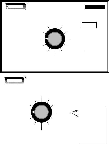
CONSOLE SWITCHES AND INDICATORS
This section shows the location of each switch and indicator found on the TASC 6100 control console and discusses its function in both the
Operate and Setup modes.
POWER SWITCH |
|
|
|
|
|
|
|
|
|
|
|
The power switch (see #1 in Fig. 1-1) controls power |
|
|
|
|
|
|
|
|
|
||
to the console. The CE console has an "Auto Power |
1 |
|
|
2 |
3 |
||||||
Down" feature which |
|
|
|
|
|||||||
|
|
|
|
|
|
|
|
|
|
|
|
powers the console off |
|
|
|
® |
|
|
|
|
|
||
Flow |
|
|
|
ON |
OPERATE INC. |
||||||
|
|
|
|
|
|
|
|
|
|
|
|
after a operator selectable |
|
-Ac |
MID- |
TECH |
|
|
|
|
|
|
|
|
|
|
|
OFF |
SETUP |
DEC. |
|||||
|
|
MIDWEST TECHNOLOGIES, INC. |
|||||||||
time has elapsed. The |
|
|
|
|
|
|
|
|
%Rate |
4 |
|
console has a nonvolatile |
|
Gal./ |
|
|
|
Product Vol. |
Appl. Rate |
||||
|
|
|
|
Fan RPM |
|
|
Total Applied |
||||
|
|
|
|
|
Area |
|
|
Width |
|||
|
|
|
|
|
Speed |
|
|
|
|||
memory so it "remembers" |
|
|
|
|
|
|
|
Distance |
|||
|
|
|
|
|
|
Scan Test PSI/Prime |
|||||
|
|
|
|
|
|
|
|
Speed |
|
||
the constants and data |
|
|
|
|
|
|
DISPLAY SELECTOR |
||||
TASC-6100 |
Alt.-Rate |
|
|
|
|
|
|
|
|
5 |
|
Standard Rate |
|
|
|
|
|
|
|
|
|||
previously entered, even |
Rate Controller |
OFF |
|
|
|
|
|
|
|
|
|
|
|
|
|
|
1 2 3 |
4 5 |
6 7 8 9 |
||||
BOOMS
with the power removed.
6
NOTE: The “Auto Power Down Feature is only available on the CE version of the console (CE designation label on back of console).
MODE SELECTOR SWITCH
The Mode Selector switch (see #2 in Fig. 1-1) switches between the OPERATE and SET-UP modes of the control console. This switch must be in the “OPERATE” position when applying product. The “SET-UP” position is used for entering set-up information into the console. In the SET-UP Mode an “Err” message appears if a position which can not be programmed is selected.
Fig. 1-1. TASC
Console Switches and
Indicators
1-1 |
CE&STANDARD VERSION |

98-05018
R2
CE&STANDARD VERSION
TASC 6100
INC / DEC SWITCH
The Increase/Decrease (INC/DEC) switch (see #3 in Fig. 1-1) is used, in both the OPERATE and SET-UP modes, to adjust the values appearing in the display.
BOOM SECTION “ON/OFF” INDICATORS
The boom section On/Off indicators (see #5 in Fig. 1- 1) indicate which boom sections the operator has selected. When a boom is turned on, its indicator is lit. There are a maximum of nine boom sections available.
RATE SWITCH
The Rate Selector switch (see #6 in Fig. 1-1) is a three position switch that allows the operator to select either a pre-selected standard rate, an alternate rate, or stop the application.
DISPLAY SELECTOR SWITCH
The Display Selector (see #4, Fig. 1-1) is used to choose which of the console functions is displayed on the screen and is available for setting by the operator.
Display Selector - Operate Mode (Liquid)
(See Fig. 1-2)
Speed: The current vehicle speed.
Area: Area Accumulator #1. The total area treated since the counter was last reset.*
Fan RPM: Not used in liquid mode.
Product Vol: Amount of product aboard the vehicle. Value counts down as the product is applied and alarm sounds when 10 % of the full load is left.**
1-2

TASC 6100
%Rate: The percent of programmed application rate at which the system is applying product.***
|
98-05018 |
|
R2 |
OPERATE |
|
® ON |
OPERATE INC. |
MID- CH |
|
SETUP |
|
OFF |
SETUP |
|
%Rate |
Product Vol. Appl. Rate |
|
Fan RPM |
Total Applied |
|
|
|
Area |
Width |
|
|
|
Speed |
Distance |
Application Rate: |
%Rate |
|
Scan |
Test PSI/Prime |
Appl. Rate |
|
Speed |
||
Product Vol. |
DISPLAY SELECTOR |
|||
Displays the |
FanTASCRPM-6100 |
Total Applied |
|
|
target application |
Rate Controller |
|
|
|
Area |
Width |
|
|
|
rate when the |
Speed |
Distance |
|
|
ground speed is |
Scan |
PSI/Prime |
|
|
Test |
|
|
||
zero or all booms |
Speed |
|
|
|
DISPLAY SELECTOR |
|
|
||
are OFF.** The |
|
|
||
|
|
Fig. 1-2. Display Selector |
||
actual application |
|
|
Functions - Operate Mode |
|
rate is displayed here once
application has started.
Switches |
Cont |
. |
|
|
|
& |
|
|
|
|
|
Total Applied: The total volume of product applied since the last time the counter was reset, as measured by the pressure sensor or flow meter.*
Impl. Width: The active boom width, (total of all boom sections turned ON).
Distance: The total distance traveled since the last time the counter was reset.
PSI/Prime: Used to open the control valve during product pump priming, for fast unload, and to display boom pressure when operating in pressure based mode.
Test Speed: The speed the console uses for stationary tests of the sprayer.**
Scan: The display scans Speed, Area #1, Product Vol., Application Rate, Total Applied, and Fan RPM, stopping at each position for approximately two seconds before automatically cycling to the next.
1-3
*Totals can be zeroed in this mode.
**Values are programmable in this mode.
***Values changeable by a % increase or decrease.
CE&STANDARD VERSION

98-05018 |
|
|
|
|
|
|
|
|
|
|
|
|
|
|
|
|
|
|
TASC 6100 |
R2 |
|
|
|
|
|
|
|
|
|
|
|
|
|
|
|
|
|
|
|
|
|
|
|
|
Display Selector |
|
- Setup Mode (Liquid) |
||||||||||||
|
|
|
|
|
|
|
|||||||||||||
|
|
|
|
|
|
|
|
(See Fig. 1-3) |
|
|
|
||||||||
|
|
|
|
|
|
|
|
|
|
|
|
|
|
|
|
|
|
|
Speed: Ground speed |
|
|
|
|
|
OPERATE |
|
|
|
|
|
|
|
|
override (GSO) value.** |
|||||
|
MPH |
|
|
|
|
|
|
|
® |
|
ON |
OPERATE |
INC. |
|
|
Area: Area Accumulator |
|||
|
|
|
|
|
|
|
|
|
|
|
|||||||||
|
|
|
|
|
SET- |
UP |
|
|
|
|
|
|
|
|
|
|
|||
|
|
|
|
|
MID-TECH |
|
|
|
|
|
|
|
|
|
|
|
|
|
|
|
|
MIDWEST TECHNOLOGIES, INC. |
|
OFF |
SETUP |
DEC. |
|
|
#2. The total area treated |
||||||||||
|
|
|
|
|
|
|
|
|
|
||||||||||
|
|
|
|
|
|
|
|
|
|
|
|
|
%Rate |
|
|
|
|
||
|
|
|
|
|
|
|
|
|
|
|
|
|
Total Applied |
since the counter was last |
|||||
|
|
|
|
|
|
|
|
|
|
Product Vol. |
|
Appl. Rate |
|
|
|||||
|
|
|
|
|
|
|
|
|
|
Fan RPM |
|
|
|
|
|
|
|
||
|
|
|
|
|
|
|
|
|
|
|
Area |
|
|
|
Width |
|
|
reset.* |
|
%Rate |
|
|
|
|
|
|
|
|
|
|
Speed |
|
|
Distance |
|
||||
|
|
|
|
|
|
|
|
|
|
|
Scan Test |
PSI/Prime |
|
|
|
||||
Product Vol. |
Appl. Rate |
|
|
|
|
|
|
|
|
Speed |
|
|
|
|
|
||||
|
|
|
|
|
|
|
DISPLAY SELECTOR |
|
|
|
|||||||||
FanTASCRPM -6100 |
|
|
|
|
|
|
|
|
|
|
|
|
|
|
|||||
Total Applied |
|
|
|
|
|
|
|
|
Fan RPM: The current fan |
||||||||||
Rate Controller |
Width |
|
|
|
|
|
|
|
|
|
|
|
|
|
|
||||
Area |
1 |
2 |
3 |
4 |
5 |
6 |
7 |
8 |
9 |
RPM. calibration number. |
|||||||||
Speed |
Distance |
|
|
|
|
|
BOOMS |
|
|
|
|
|
|
||||||
|
|
|
|
|
|
|
|
|
|
|
|
|
|
Since not used in liquid |
|||||
Test PSI/Prime |
|
|
|
|
|
|
|
|
|
|
|
|
|
|
|||||
Scan |
|
|
|
|
|
|
|
|
|
|
|
|
|
|
|
|
|
|
|
Speed |
|
|
|
|
|
|
|
|
|
|
mode, can be set to zero to remove the fan |
||||||||
DISPLAY SELECTOR |
|
|
|
RPM reading from the scan feature.** |
|||||||||||||||
|
|
|
|
|
|
|
|
||||||||||||
Fig. 1-3. Display Selector
Functions - Set-Up Mode
Product Volume: Used to set the full load value of the vehicle.**
%Rate: The percent rate change value (the percent by which the programmed application rate can be changed with each activation of the INC/DEC switch).**
Application Rate: Psi mode - A flow sensor cal. # correction factor that allows for corrections due to differences in product viscosities without changing the base cal. #. STnrd and rEFLO modes - ERR, No function in this mode.
Total Applied: The pressure sensor or flow meter
*Totals can be zeroed in this mode.
**Values are programmable in this mode.
***Values changeable by a % increase or decrease.
CE&STANDARD VERSION
calibration number. NOTE: Must have all booms ON when in REFLOW Mode.**
Width: Individual boom section widths. The display cycles through the individual boom sections, in order, unless a particular boom switch is activated and the boom master switch is ON.**
Distance: The current distance calibration number.**
PSI/Prime: The current console operating mode.**
Test Speed: The current test speed.**
Scan: ERR, No function in SETUP mode.
1-4
TASC 6100
Display Selector - Operate Mode (Gran.)
(See Fig. 1-2)
Speed: The current vehicle speed.
Area: Area Accumulator #1. The total area treated since the counter was last reset.*
Fan RPM: The current speed of the fan (spinners).
Product Vol.: Amount of product aboard the vehicle.**
%Rate: The percent of programmed application rate at which the product is being applied.***
Application Rate: Displays the target application rate, when the ground speed is zero or all booms are OFF. ** Once application begins, the actual application rate is displayed here.
Total Applied: The total volume applied since the accumulator was last reset, as measured by the rate sensor.*
Impl. Width: The active spread width, (total of all spreader sections turned “ON”).
Distance: The total distance traveled since the last time the counter was reset.
Prime: Used to open the control valve. It can be used in the granular application to unload the vehicle at its maximum discharge rate.
Test Speed: The speed the console uses for stationary tests of the spreader.**
Scan: The display scans Speed, Area #1, Product Volume, Application Rate, Total Applied, and Fan RPM (if Fan RPM Cal # not set to zero). The display stops at each position for approximately two seconds before automatically cycling to the next.
1-5
98-05018
R2
Switches |
Cont |
. |
|
|
|
& |
|
|
|
|
|
*Totals can be zeroed in this mode.
**Values are programmable in this mode.
***Values changeable by a % increase or decrease.
CE&STANDARD VERSION

98-05018 |
|
TASC 6100 |
R2 |
|
|
|
|
|
Display Selector |
- Set-Up Mode (Gran.) |
|
(See fig. 1-3) |
|
|
Speed: Ground Speed Override (GSO) value.**
Area: Area Accumulator #2. The total area treated since the counter was last reset.*
Fan RPM: The current fan RPM calibration number. This cal # can be set to zero to remove the fan RPM reading from the scan feature.**
Product Volume: Used to set the full load capacity of the vehicle.**
*Totals can be zeroed in this mode.
**Values are programmable in this mode.
***Values changeable by a % increase or decrease.
%Rate: The percent rate change value (the percent by which the programmed application rate can be changed with each activation of the INC/DEC switch).**
Application Rate: Product density.**
Total Applied: The rate sensor calibration number [spreader constant].**
Width: Individual boom section widths.**
Distance: The current distance calibration number.**
Prime: The current console operating mode.**
Test Speed: The current test speed.**
Scan: Err, No function in the SETUP mode.
IMPLEMENT STATUS INPUT
An external “Implement Status” input can be used to override the TASC control. The input must present a positive voltage (+12.0
VDC) on the boom interface cable sense line. As long as this condition is present, the control console operates normally. If the voltage is interrupted, the control console automatically stops applying. At the same time, the control console will either "HOLD" or
CE&STANDARD VERSION |
1-6 |

TASC 6100
"CLOSE" the control valve, depending on the response selected by the operator. (See Page 2-7).
This feature allows the operator to control the operation of the control valve through the normal operation of the vehicle. The implement status input can be used to sense the ON/OFF condition of the main vehicle pump switch, a separate Master switch, or, an external switch sensing an implement "UP"/ "DOWN" condition.
GROUND SPEED OVERRIDE SWITCH (GSO)
If your TASC system includes an optional MIDTECH® Boom Control Switch Box, the GSO switch is already installed. An optional, externally
mounted, GSO switch can be used to temporarily operate the vehicle using a pre-selected GSO minimum speed rather than the actual speed registered by the ground speed sensor. The override feature is used to allow the vehicle to reach the application rate quickly when starting from a complete stop or to maintain a good application pattern when the vehicle is moving at very low ground speeds. It can also be used to allow the operator to flush or empty the tank of a sprayer, or empty the bed of a spreader, from the cab, with the vehicle stopped.
98-05018
R2
Switches |
Cont |
. |
|
|
|
& |
|
|
|
|
|
Fig. B-8, in Appendix B, shows a “Boom Control Switch Box” which incorporates the Implement Status Switch and the GSO function into one switch. The “OFF” position provides a Status Switch “OFF” condition, “AUTO” furnishes Status Switch ON, and “GSO” activates the GSO function. Other methods of controlling these functions are also available. This switchbox also includes an individual ON/OFF switch for each boom section.
The control console operates normally as long as the GSO switch condition is open (OFF). Whenever the override switch is closed (ON) and the actual ground speed is less than the GSO Speed, the control console automatically uses the GSO Speed to control application rate. As soon as the switch reverts to its normally open (OFF) condition, or the actual ground speed increases above the preset GSO speed, the control console will adjust the rate based on the actual ground speed.
MMid-Teechh
-T
CAUTION: Controlling application rates based on a GSO Speed is not as accurate as using the actual ground speed. When GSO is being used and the true ground speed is less than the GSO speed", the console sounds an alarm and the display flashes a "Too Slow" message to warn the operator of over application.
1-7 |
CE&STANDARD VERSION |

98-05018 |
TASC 6100 |
R2 |
|
|
R |
MID-TECH |
TASC 6100, DISPLAYED VALUES WHEN IN OPERATE
MIDWEST TECHNOLOGIES, INC.
Specialists In Control System Electronics Since 1983
% Rate
Use INC switch to set full load,
INC/DEC to change Product Vol.
Fan RPM
Area
Use DEC switch to zero display
Speed
Scan
Test Speed
|
|
SOFTWARE VER. 1.30 |
|
|
LIQUID STD MODE |
Use INC/DEC switch to change up or down |
Preset #1 |
|
|
|
|
100 |
|
|
|
Use INC/DEC switch to change up or down |
|
Application Rate 10.0/12.0
Total Applied
Use DEC switch to zero display
Impl. Width
Distance
Hold increase switch to drive valve OPEN
PSI/Prime -----
10.0
Use INC/DEC switch to change up or down
Default values shown in upper left of boxes.
|
|
|
|
|
|
|
|
|
|
|
|
|
|
|
|
|
|
|
|
|
|
|
|
|
|
|
|
|
|
|
|
|
|
|
R |
|
|
|
|
|
|
|
|
|
|
|
|
|
|
|
|
|
|||||
|
|
|
|
|
|
|
|
|
|
|
|
|
|
|
|
SET-UP |
|
|
|
|||||||||
|
MID-TECH |
|
|
|
TASC 6100, DISPLAYED VALUES WHEN IN |
|
|
|
||||||||||||||||||||
|
MIDWEST TECHNOLOGIES, INC. |
|
|
|
|
|
|
|
|
|
|
SOFTWARE VER. 1.30 |
|
|||||||||||||||
|
|
|
|
|
|
|
|
|
|
|
LIQUID STD MODE |
|
||||||||||||||||
|
Specialists In Control System Electronics Since 1983 |
|
|
|
|
|
|
|
|
|
|
|
||||||||||||||||
|
|
|
|
|
|
|
|
|
|
|
Rate Change Increment |
|
|
Preset #1 |
|
|
|
|
||||||||||
|
|
|
|
|
|
|
% Rate |
10 |
|
|
|
|
|
|
|
|
|
|
|
|
|
|
|
|
|
|||
|
|
|
|
|
Full Load Amount |
|
|
|
|
|
Correction factor |
|
|
|
|
|
|
|
|
|
||||||||
|
Product Vol. |
|
Application Rate |
|
|
|
|
|
|
|
|
|
||||||||||||||||
|
500 |
|
|
|
|
|
1.00 |
|
|
|
|
|
|
|
|
|
|
|
|
|||||||||
|
|
|
|
|
|
|
|
|
|
|
|
|
|
|
|
|
|
|
|
|
|
|
|
|
|
|
|
|
|
Fan RPM |
|
|
|
|
|
|
|
|
|
Total Applied |
Rate Sensor Cal# |
|
|
|
|
|
|
|
|
|
|||||||
|
|
|
|
|
|
|
|
|
|
|
|
|
|
|
|
|
|
|
||||||||||
|
|
2.00 |
|
|
|
|
|
|
|
71.0 |
|
|
|
|
|
|
|
|
|
|||||||||
|
|
|
|
|
|
|
|
|
|
|
|
|
|
|
|
|
|
|
|
|
|
Default |
Custom |
|
||||
|
Area |
|
|
|
|
|
|
|
|
|
|
Impl. Width |
|
|
|
|||||||||||||
|
0.0 |
|
|
|
|
|
|
|
|
C |
960 |
|
|
|
|
|
||||||||||||
|
|
|
|
|
|
|
|
|
|
|
|
|
|
|
|
|
|
|
|
|
|
|
|
|
|
|
||
|
|
|
|
|
|
|
|
|
|
|
|
|
|
|
|
|
|
|
|
1 |
|
120 |
|
|
|
|
|
|
|
|
|
|
|
|
|
|
|
|
|
|
|
|
|
|
|
|
|
|
|
|
|
|
|
||||
|
|
Ground Speed Override |
|
|
|
Distance Sensor Cal# |
2 |
|
|
|
|
|
|
|
|
|||||||||||||
|
Speed |
Distance |
|
200 |
|
|
|
|
|
|||||||||||||||||||
|
7.0 |
|
|
|
|
|
|
|
1000 |
|
|
|
|
|
|
|
|
|
||||||||||
|
|
|
|
|
|
|
|
|
|
|
3 |
|
|
|
|
|
|
|
|
|||||||||
|
|
|
|
|
|
|
|
|
|
|
|
|
|
|
|
|
|
|
|
|
320 |
|
|
|
|
|
||
|
|
|
|
|
|
|
|
|
|
|
|
|
|
|
|
|
|
|
|
4 |
|
|
|
|
|
|
||
|
|
|
Scan |
|
|
|
|
|
|
|
PSI/Prime |
DEC sets to granular |
5 |
|
200 |
|
|
|
|
|
||||||||
|
|
|
|
Err |
|
|
|
|
INC sets to liquid |
|
|
|
|
|
|
|
|
|
||||||||||
|
|
|
|
|
|
|
|
Stnrd L |
|
6 |
|
120 |
|
|
|
|
|
|||||||||||
|
|
|
|
|
|
|
|
|
|
|
|
|
|
|
|
|
|
|
|
|
||||||||
|
|
|
|
|
|
Test Speed |
|
|
|
|
|
|
|
|
|
|
7 |
|
0 |
|
|
|
|
|
||||
|
|
|
|
|
|
|
10.0/ |
|
|
|
|
|
|
|
|
8 |
|
|
|
|
|
|
|
|
||||
|
|
|
|
|
|
|
|
|
|
|
|
|
|
|
|
|
|
|
|
|
0 |
|
|
|
|
|
||
|
|
|
|
|
|
|
|
|
|
|
|
|
|
|
|
|
|
|
|
9 |
|
|
|
|
|
|
||
|
Default values shown in upper left of boxes. |
|
0 |
|
|
|
|
|
||||||||||||||||||||
|
|
|
|
|
|
|
|
|||||||||||||||||||||
|
|
|
0 |
|
|
|
|
|
||||||||||||||||||||
|
Use the INC/DEC switch to change values. |
|
|
|
|
|
|
|
|
|
|
|
|
|
|
|
||||||||||||
|
|
|
|
|
|
|
|
|
|
|
|
|
|
|
|
|
|
|
|
|
|
|
|
|
|
|
|
|
|
|
|
|
|
|
|
|
|
|
|
|
|
|
|
|
|
|
|
|
|
|
|
|
|
|
|
|
|
99362
Fig. 1-4. TASC 6100 Default Values
- Liquid Standard Mode
CE&STANDARD VERSION |
1-8 |

TASC 6100 |
98-05018 |
|
R2 |
|
Switches |
Cont |
. |
|
|
|
& |
|
|
|
|
|
R |
MID-TECH |
TASC 6100, DISPLAYED VALUES WHEN IN OPERATE
MIDWEST TECHNOLOGIES, INC.
Specialists In Control System Electronics Since 1983
% Rate
Use INC switch to set full load,
INC/DEC to change Product Vol.
Fan RPM
Area
Use DEC switch to zero display
|
|
SOFTWARE VER. 1.30 |
|
|
LIQUID PSI MODE |
Use INC/DEC switch to change up or down |
Preset #1 |
|
100 |
|
|
|
Use INC/DEC switch to change up or down |
|
Application Rate 10.0
Total Applied
Use DEC switch to zero display
Impl. Width
Speed |
|
Distance |
||
|
|
Hold increase switch to drive valve OPEN |
||
Scan |
PSI/Prime |
Ps--- |
|
|
Test Speed |
|
|
|
|
10.0 |
|
|
|
|
|
|
|
||
|
Use INC/DEC switch to change up or down |
|||
Default values shown in upper left of boxes.
|
|
|
|
|
|
|
|
|
|
|
|
|
|
|
|
|
|
|
|
|
|
|
|
|
|
|
|
|
|
|
|
|
|
|
|
|
R |
|
|
|
|
|
|
|
|
|
|
|
|
|
|
|
|
|
|
|
|||||
|
|
|
|
|
|
|
|
|
|
|
|
|
|
|
|
|
|
SET-UP |
|
|
|
|
||||||||
|
MID-TECH |
|
|
|
|
TASC 6100, DISPLAYED VALUES WHEN IN |
|
|
|
|
||||||||||||||||||||
|
MIDWEST TECHNOLOGIES, INC. |
|
|
|
|
|
|
|
|
|
|
|
SOFTWARE VER. 1.30 |
|
|
|
||||||||||||||
|
|
|
|
|
|
|
|
|
|
|
|
LIQUID PSI MODE |
|
|
|
|||||||||||||||
|
Specialists In Control System Electronics Since 1983 |
|
|
|
|
|
|
|
|
|
|
|
|
|
|
|||||||||||||||
|
|
|
|
|
|
|
|
|
|
|
Rate Change Increment |
|
|
Preset #1 |
|
|
|
|
|
|||||||||||
|
|
|
|
|
|
|
|
|
|
|
|
|
|
|
|
|
|
|
|
|
||||||||||
|
|
|
|
|
|
|
% Rate |
10 |
|
|
|
|
|
|
|
|
|
|
|
|
|
|
|
|
|
|
|
|||
|
|
|
|
|
Full Load Amount |
|
|
|
|
|
Correction factor |
|
|
|
|
|
|
|
|
|
|
|||||||||
|
Product Vol. |
|
Application Rate |
|
|
|
|
|
|
|
|
|
|
|||||||||||||||||
|
500 |
|
|
|
|
|
1.00 |
|
|
|
|
|
|
|
|
|
|
|
|
|
|
|||||||||
|
|
|
|
|
|
|
|
|
|
|
|
|
|
|
|
|
|
|
|
|
|
|
|
|
|
|
|
|
||
|
Fan RPM |
|
|
|
|
|
|
|
|
Total Applied |
Rate Sensor Cal# |
|
|
|
|
|
|
|
|
|
|
|||||||||
|
|
|
|
|
|
|
|
|
|
|
|
|
|
|
|
|
|
|
||||||||||||
|
2.00 |
|
|
|
|
|
|
|
10.0/12.0 |
|
|
|
|
|
|
|
|
|
|
|||||||||||
|
Area |
|
|
|
|
|
|
|
|
|
|
|
|
|
|
|
|
|
|
|
|
Default |
Custom |
|
|
|
||||
|
|
|
|
|
|
|
|
|
|
|
Impl. Width |
|
|
|
|
|
||||||||||||||
|
0.0 |
|
|
|
|
|
|
|
|
C |
960 |
|
|
|
|
|
|
|
||||||||||||
|
|
|
|
|
|
|
|
|
|
|
|
|
|
|
|
|
|
|
|
|
|
|
|
|
|
|
|
|
||
|
|
|
|
|
|
|
|
|
|
|
|
|
|
|
|
|
|
|
|
|
1 |
|
120 |
|
|
|
|
|
|
|
|
|
|
|
|
|
|
|
|
|
|
|
|
|
|
|
|
|
|
|
|
|
|
|
|
|
|
|
|||
|
|
Ground Speed Override |
|
|
|
Distance Sensor Cal# |
2 |
|
|
|
|
|
|
|
|
|
||||||||||||||
|
Speed |
Distance |
|
200 |
|
|
|
|
|
|
|
|||||||||||||||||||
|
7.0 |
|
|
|
|
|
|
|
1000 |
|
|
|
|
3 |
|
|
|
|
|
|
|
|
|
|||||||
|
|
|
|
|
|
|
|
|
|
|
|
|
|
|
|
|
|
|
|
|
|
320 |
|
|
|
|
|
|
|
|
|
|
|
|
|
|
|
|
|
|
|
|
|
|
|
|
|
|
|
|
|
4 |
|
|
|
|
|
|
|
|
|
|
|
|
Scan |
|
|
|
|
|
|
|
PSI/Prime |
DEC sets to granular |
5 |
|
200 |
|
|
|
|
|
|
|
||||||||
|
|
|
|
Err |
|
|
|
|
INC sets to liquid |
|
|
|
|
|
|
|
|
|
|
|||||||||||
|
|
|
|
|
|
|
|
|
|
|
|
|
|
PSi |
|
|
6 |
|
120 |
|
|
|
|
|
|
|
||||
|
|
|
|
|
|
Test Speed |
|
|
|
|
|
|
|
|
|
|
|
7 |
|
0 |
|
|
|
|
|
|
|
|||
|
|
|
|
|
|
|
10.0 |
|
|
|
|
|
|
|
|
|
8 |
|
|
|
|
|
|
|
|
|
||||
|
|
|
|
|
|
|
|
|
|
|
|
|
|
|
|
|
|
|
|
|
|
|
||||||||
|
|
|
|
|
|
|
|
|
|
|
|
|
|
|
|
|
|
|
|
|
|
0 |
|
|
|
|
|
|
|
|
|
|
|
|
|
|
|
|
|
|
|
|
|
|
|
|
|
|
|
|
|
9 |
|
|
|
|
|
|
|
|
|
|
Default values shown in upper left of boxes. |
|
0 |
|
|
|
|
|
|
|
||||||||||||||||||||
|
|
|
|
|
|
|
|
|
|
|||||||||||||||||||||
|
|
|
0 |
|
|
|
|
|
|
|
||||||||||||||||||||
|
Use the INC/DEC switch to change values. |
|
|
|
|
|
|
|
|
|
|
|
|
|
|
|
|
|
|
|||||||||||
|
|
|
|
|
|
|
|
|
|
|
|
|
|
|
|
|
|
|
|
|
|
|
|
|
|
|
|
|
|
|
|
|
|
|
|
|
|
|
|
|
|
|
|
|
|
|
|
|
|
|
|
|
|
|
|
|
|
|
|
|
|
99362
Fig. 1-5. TASC 6100 Default Values
- Liquid Pressure Mode
1-9 |
CE&STANDARD VERSION |
98-05018 |
TASC 6100 |
R2 |
|
|
R |
MID-TECH |
TASC 6100, DISPLAYED VALUES WHEN IN OPERATE
MIDWEST TECHNOLOGIES, INC.
Specialists In Control System Electronics Since 1983
% Rate
Use INC switch to set full load,
INC/DEC to change Product Vol.
Fan RPM
Area
Use DEC switch to zero display
|
|
SOFTWARE VER. 1.30 |
|
|
GRANULAR MODE |
Use INC/DEC switch to change up or down |
Preset #1 |
|
100 |
|
|
|
Use INC/DEC switch to change up or down |
|
|
||
Application Rate 200/250
Total Applied
Use DEC switch to zero display
Impl. Width
Speed |
|
Distance |
||||
|
|
Hold increase switch to drive valve OPEN |
||||
Scan |
PSI/Prime |
|
----- |
|
|
|
|
|
|||||
Test Speed |
|
|
|
|
|
|
10.0 |
|
|
|
|
|
|
|
|
|
||||
|
Use INC/DEC switch to change up or down |
|||||
Default values shown in upper left of boxes.
|
|
|
|
|
|
|
|
|
|
|
|
|
|
|
|
|
|
|
|
|
|
|
|
|
|
|
|
|
|
|
|
|
|
|
|
|
|
|
|
|
|
|
|
|
|
|
|
|
|
|
|
|
|
|
|
|
|
|
|
|
|
|
|
|
|
|
|
|
|
|
R |
|
|
|
|
|
|
|
|
|
|
|
|
SET-UP |
|
|
|
||||||||
|
MID-TECH |
|
|
|
|
TASC 6100, DISPLAYED VALUES WHEN IN |
|
|
|
||||||||||||||||||||||
|
|
|
|
|
|
|
|
|
|
|
|
|
|
|
|
|
|
|
|
|
|
|
|
SOFTWARE VER. 1.30 |
|
||||||
|
MIDWEST TECHNOLOGIES, INC. |
|
|
|
|
|
|
|
|
|
|
|
GRANULAR MODE |
|
|||||||||||||||||
|
Specialists In Control System Electronics Since 1983 |
|
|
|
|
|
|
|
|
|
|
|
Preset #1 |
|
|
|
|
||||||||||||||
|
|
|
|
|
|
|
|
|
|
|
|
Rate Change Increment |
|
|
|
|
|
|
|||||||||||||
|
|
|
|
|
|
|
|
|
|
|
|
|
|
|
|
|
|
|
|
|
|
||||||||||
|
|
|
|
|
|
|
|
% Rate |
10 |
|
|
|
|
|
|
|
|
|
|
|
|
|
|
|
|
|
|
|
|||
|
|
|
|
|
|
Full Load Amount |
|
|
|
|
|
Density |
|
|
|
|
|
|
|
|
|
|
|||||||||
|
Product Vol. |
|
Application Rate |
|
|
|
|
|
|
|
|
|
|
||||||||||||||||||
|
10750 |
|
|
|
|
|
65.0 |
|
|
|
|
|
|
|
|
|
|
|
|
|
|
||||||||||
|
|
|
|
|
|
|
|
|
|
|
|
|
|
|
|
|
|
|
|
|
|
|
|
|
|
|
|
|
|
||
|
Fan RPM |
|
|
|
|
|
|
|
|
|
Total Applied |
Rate Sensor Cal# |
|
|
|
|
|
|
|
|
|
|
|||||||||
|
|
|
|
|
|
|
|
|
|
|
|
|
|
|
|
|
|
|
|
||||||||||||
|
|
2.00 |
|
|
|
|
|
|
|
1630.0 |
|
|
|
|
|
|
|
|
|
|
|||||||||||
|
|
|
|
|
|
|
|
|
|
|
|
|
|
|
|
|
|
|
|
|
|
|
|
Default |
Custom |
|
|||||
|
|
|
|
|
|
|
|
|
|
|
|
|
|
|
|
|
|
|
|
|
|
|
|
|
|||||||
|
|
|
|
|
|
|
|
|
|
|
|
|
|
Impl. Width |
|
|
|
||||||||||||||
|
Area |
0.0 |
|
|
|
|
|
|
|
|
|
C |
720 |
|
|
|
|
|
|
|
|||||||||||
|
|
|
|
|
|
|
|
|
|
|
|
|
|
|
|
|
|
|
|
|
|
1 |
|
360 |
|
|
|
|
|
|
|
|
|
|
|
|
|
|
|
|
|
|
|
|
|
|
|
|
|
|
|
|
|
|
|
|
|
|
|
|
|||
|
Speed |
Ground Speed Override |
Distance |
Distance Sensor Cal# |
2 |
|
360 |
|
|
|
|
|
|
|
|||||||||||||||||
|
7.0 |
|
|
|
|
|
|
|
|
1000 |
|
|
|
|
3 |
|
|
|
|
|
|
|
|
|
|||||||
|
|
|
|
|
|
|
|
|
|
|
|
|
|
|
|
|
|
|
|
|
|
|
0 |
|
|
|
|
|
|
|
|
|
|
|
|
|
|
|
|
|
|
|
|
|
|
|
|
|
|
|
|
|
|
4 |
|
|
|
|
|
|
|
|
|
|
|
|
Scan |
|
|
|
|
|
|
|
PSI/Prime |
DEC sets to granular |
5 |
|
0 |
|
|
|
|
|
|
|
|||||||||
|
|
|
|
Err |
|
|
|
|
INC sets to liquid |
|
|
|
|
|
|
|
|
|
|
||||||||||||
|
|
|
|
|
|
|
|
|
|
|
|
|
|
|
Stnrd C |
|
|
6 |
|
0 |
|
|
|
|
|
|
|
||||
|
|
|
|
|
|
|
|
|
|
|
|
|
|
|
|
|
|
|
|
|
|
|
|
||||||||
|
|
|
|
|
|
|
Test Speed |
|
|
|
|
|
|
|
|
|
|
|
7 |
|
0 |
|
|
|
|
|
|
|
|||
|
|
|
|
|
|
|
|
10.0 |
|
|
|
|
|
|
|
|
|
|
|
|
|
|
|
|
|
||||||
|
|
|
|
|
|
|
|
|
|
|
|
|
|
|
|
|
|
|
|
|
|
8 |
|
0 |
|
|
|
|
|
|
|
|
Default values shown in upper left of boxes. |
9 |
|
0 |
|
|
|
|
|
|
|
||||||||||||||||||||
|
|
|
|
|
|
|
|
|
|
||||||||||||||||||||||
|
|
|
0 |
|
|
|
|
|
|
|
|||||||||||||||||||||
|
Use the INC/DEC switch to change values. |
|
|
|
|
|
|
|
|
|
|
|
|
|
|
|
|
|
|
||||||||||||
|
|
|
|
|
|
|
|
|
|
|
|
|
|
|
|
|
|
|
|
|
|
|
|
|
|
|
|
|
|
|
|
|
|
|
|
|
|
|
|
|
|
|
|
|
|
|
|
|
|
|
|
|
|
|
|
|
|
|
|
|
|
|
|
99362
Fig. 1-6. TASC 6100 Default Values
- Granular Mode
CE&STANDARD VERSION |
1-10 |

TASC 6100
CHAPTER 2 CALIBRATION
NOTE: PLEASE READ THROUGH THE FOLLOWING SECTIONS COMPLETELY BEFORE YOU BEGIN CALIBRATION!
Specific information about your applicator (i.e. application rates, boom widths, test speed, etc.) must be programmed into the control console and
the flow/rate and ground speed sensors must be calibrated before the system is ready to use. The calibration and set up procedures are not difficult but must be followed precisely in order to get the maximum possible accuracy out of the system.
98-05018
R2
Mid-Tech
Mid-Tech
|
|
|
|
|
|
|
|
|
|
|
|
Setup |
|
Cal |
|
|
|
|
. |
|
|
|
& |
|
|
|
|
|
|
SELECTING THE APPLICATION PROGRAM
8erify that the proper console application pro gram is selected.
To view the program currently selected, set the Mode switch to Setup and the Display Selector to PSI/Prime.
Pump L PSi(bAr) is LIQUID PRESSURE application (normal pressure based spraying) Pump L STnrd is STANDARD LIQUID application (normal flow based spraying) Pump L rEFLO is LIQUID REFLOW application (for use on some European sprayers) Pump C STnrd is standard GRANULAR application (single conveyor spreaders) Pump C SPLit is GRANULAR SPLIT DRIVE application (dual conveyor spreaders)
To change programs, hold the INC. switch up to set LIQUID and cycle between standard, reflow, and pressure. Hold the DEC. switch down to set GRANULAR and cycle between standard and split drive. The display changes about every ten seconds. The program being displayed, when the INC./ DEC. switch is released, is the program selected. If you have a question about which application to use, check with your dealer or call MID-TECH Customer Service.
SELECTING ENGLISH OR METRIC, UNITS
The control console is capable of displaying either
US or Metric units of measure.
2-1 |
CE & StandardVersion |

98-05018 |
|
|
|
|
|
|
|
TASC 6100 |
||
|
R2 |
|
|
|
|
|
|
|
||
|
|
|
|
|
|
|
|
|
||
UNITS FOR EACH DISPLAY SELECTOR SWITCH POSITION |
||||||||||
|
|
(Liquid Mode)** |
|
|
|
|
|
|||
|
|
|
|
|
|
|
||||
POSITION |
|
US |
|
METRIC |
|
|
||||
Speed |
Miles/Hour |
(mph) |
Kilometers/Hour |
(kmph) |
|
|||||
Field |
Area |
Acres |
(acre) |
|
Hectares |
(ha) |
|
|
||
Total |
Area |
Acres |
(acre) |
|
Hectares |
(ha) |
|
|
||
Product Vol. |
US |
Gallons |
(gal.) |
Liters (l) |
|
|
|
|||
Appl. Rate |
US |
Gallons/acre (gpa) |
Liters/Hectare (l/ha) |
|||||||
Total |
Applied |
US |
Gallons |
(gal.) |
Liters (l) |
|
|
|
||
Impl. Width |
Inches - Feet (in., ft.) |
Meters (m) |
|
|
||||||
Distance |
Feet - Miles (ft.-miles)* |
Meters - Kilometers (m-km)* |
||||||||
Test Speed |
Miles/Hour |
(mph) |
Kilometers/Hour |
(kmph) |
||||||
UNITS FOR EACH DISPLAY SELECTOR SWITCH POSITION |
||||||||||
|
|
(Granular Mode)** |
|
|
|
|
||||
|
|
|
|
|
|
|
|
|||
|
POSITION |
|
|
US |
|
METRIC |
|
|
||
|
Speed |
Miles/Hour (MPH) |
Kilometers/Hour (KPH) |
|
||||||
Field |
Area |
Acres |
(Ac) |
|
Hectares |
(-Ha) |
|
|
||
Total |
Area |
Acres |
(Ac) |
|
Hectares |
(-Ha) |
|
|
||
Product Vol. |
Pounds (lb) |
Kilograms |
|
Appl. Rate |
pounds/Acre (lb/Ac) |
Kilograms/Hectare |
(-Ha) |
Total Applied |
Pounds-Tons (lb -Tons) |
Kilograms-Metric |
Tons |
Impl. Width |
Inches-Feet (In.-Ft.) |
Meters (Meters) |
|
Distance |
Feet-Miles (Ft.)* |
Meters-Kilometers |
(Meters)* |
Test Speed |
Miles/Hour (MPH) |
Kilometers/Hour (KPH) |
|
Prod. Density |
Pounds/Cubic Ft. (Cu Ft.) |
Kilograms/Tenths Meter3 (Meters Cu) |
|
*No units displayed after roll over of feet to miles or meters to kilometers
**Items in parenthesis are the abbreviations that appear on the screen.
CHANGING UNITS
A-1 |
A-2 |
B |
|
||
ON |
OPERATE |
INC. |
OFF |
SETUP |
DEC. |
|
|
|
|
% Rate |
|
|
|
|
|
|
Product Vol. |
Application Rate |
|||||
|
Fan RPM |
|
|
Total Applied |
||||
A-3 |
|
Area |
|
|
Impl. Width |
|||
|
|
Speed |
|
|
Distance |
|
||
|
|
|
Scan |
|
PSI/Prime |
|
||
|
|
|
|
Test |
|
|
|
|
|
|
|
|
Speed |
|
|
|
|
|
|
DISPLAY SELECTOR |
|
|
||||
1 |
2 |
3 |
4 |
5 |
6 |
7 |
8 |
9 |
BOOMS |
|
|
|
|
|
|
||
A. Set the console switches to the following positions:
1. Power |
ON |
2. Mode Selector |
OPERATE |
3. Display selector |
Speed |
The display shows the current speed units.
B.Hold down the INC./DEC. switch for approximately 5 sec. The display alternates between MPH (US) and KPH (Metric). Release the switch when the mode that you desire is being displayed.
CE&STANDARD VERSION |
2-2 |

TASC 6100
LIQUID/GRANULAR COMMON SETUP ITEMS
SETTING APPLICATION RATES
The TASC 6100 system is designed to maintain a constant, pre-selected application rate. In order for the control console to do this, the operator must
enter the desired application rate. Two, switch selectable, rates can be pre-programmed into the console.
Standard Rate
A. Set the console switches to the following positions:
1. Power |
ON |
2. Mode Selector |
OPERATE |
(APPLICATION RATE IS SET IN THE OPERATE MODE!!!)
3. |
Display Selector |
Application Rate |
4. |
Rate switch |
Standard Rate |
The display shows the current application rate.
B. Use the INC./DEC. switch to set the desired rate.
Alternate Rate
C. Set the console switches to the following positions:
1. Power |
ON |
2. Mode Selector |
OPERATE |
(APPLICATION RATE IS SET IN THE OPERATE MODE!!!)
3. |
Display Selector |
Application Rate |
4. |
Rate switch |
Alt.- Rate |
The display shows the current application rate.
D. Use the INC./DEC. switch to set the desired rate.
SETTING THE % RATE CHANGE
This feature allows the operator to change the application rate “ON THE GO” with a simple actuation of the INC./DEC. switch. The amount of
change each switch actuation makes is proportional to the value programmed into this position, (e.g. 20 =20%
2-3
98-05018
R2
A-1 |
A-2 |
B |
|
|
ON |
OPERATE |
INC. |
|
Setup |
|
Cal |
. |
OFF |
SETUP |
DEC. |
A-3 |
|
& |
|
|
|
|
|
|||||
|
|
|
|
|
|
|
% Rate |
|
Product Vol. |
Application Rate |
Fan RPM |
Total Applied |
Area |
Impl. Width |
Speed |
Distance |
Scan |
PSI/Prime |
Test |
|
Speed |
|
DISPLAY SELECTOR
1 2 3 4 5 6 7 8 9
BOOMS
Alt.-Rate
Standard Rate
OFF |
A-4 |
|
Setting the APPLICATION RATE to 0.0 will turn off the flow control function.
A-1 |
A-2 |
B |
|
ON OPERATE INC.
OFF SETUP DEC.
A-3
% Rate |
|
Product Vol. |
Application Rate |
Fan RPM |
Total Applied |
Area |
Impl. Width |
Speed |
Distance |
Scan |
PSI/Prime |
Test |
|
Speed |
|
DISPLAY SELECTOR
1 2 3 4 5 6 7 8 9
BOOMS
Alt.-Rate 
Standard Rate 
A-4
OFF
CE & StandardVersion

98-05018
R2
A-1 |
A-2 |
B |
|
ON OPERATE INC.
OFF |
SETUP |
DEC. |
A-3
% Rate |
|
Product Vol. |
Application Rate |
Fan RPM |
Total Applied |
Area |
Impl. Width |
Speed |
Distance |
Scan |
PSI/Prime |
Test |
|
Speed |
|
DISPLAY SELECTOR
1 2 3 4 5 6 7 8 9
BOOMS
TASC 6100
change in the target rate). For example, with the application rate set to 10.0 gallons per acre, a single actuation of the INC. switch causes the system to control flow at the rate of 12.0 gallons per acre (10.0 + 20% = 12.0).
A. Set the console switches to the following positions:
1. Power |
ON |
2. Mode Selector |
SET-UP |
3. Display Selector |
% Rate |
The display shows the current % change value.
B.Use the INC./DEC. switch to set this number to the desired % change value.
SETTING BOOM WIDTHS
|
|
|
|
|
|
|
|
|
|
he MID-TECH control console is designed to |
|
|
|
|
|
|
|
|
|
|
|
automatically compensate for changes in the swath |
|
|
|
|
|
|
|
|
|
|
|
Twidth, caused by turning boom sections on or off. |
|
|
|
|
|
|
|
|
|
|
|
To accurately respond to changes in swath width, the |
|
|
A-1 |
A-2 |
E |
|
B, C, D, E |
|
console must know the length of each boom section. Use |
||||
|
|
|
the following procedure to set boom section widths. |
||||||||
|
|
|
|
|
|
|
|
|
|
||
|
|
ON |
|
OPERATE |
INC. |
|
|
|
|
||
|
|
OFF |
|
SETUP |
DEC. |
|
|
A. Set the console to the following positions; |
|||
|
|
|
|
|
|
|
|||||
|
|
|
|
% Rate |
|
|
|
A-3 |
1. Power |
ON |
|
|
|
Product Vol. |
Application Rate |
||||||||
|
Fan RPM |
|
|
Total Applied |
|
2. Mode Selector |
SETUP |
||||
|
|
Area |
|
|
Impl. Width |
|
|||||
|
|
|
Scan |
PSI/Prime |
|
|
3. Display Selector |
Impl. Width |
|||
|
|
Speed |
|
|
Distance |
|
|
|
|||
|
|
|
|
Test |
|
|
|
|
4. Boom switches |
OFF |
|
|
|
|
|
Speed |
|
|
|
|
|||
|
|
DISPLAY SELECTOR |
|
|
|||||||
1 |
2 |
3 |
4 |
5 |
6 |
7 |
8 |
9 |
|
(or Master switch) |
|
|
|
|
|||||||||
BOOMS |
|
|
|
|
|
|
|
The display cycles through each boom position (1 |
|||
|
|
|
|
|
|
|
|
|
|
||
|
|
|
|
|
|
|
|
|
|
through 9) and displays its current width in inches |
|
|
|
|
|
|
|
|
|
|
|
(meters). |
|
|
|
MASTER |
|
|
|
|
|
|
|
||
A-4 |
|
|
|
|
|
|
|
|
|
B. As each boom position appears on the display, use |
|
|
|
|
|
|
ON |
|
|
MI |
|
||
|
|
|
|
|
|
|
|
|
the INC./DEC. switch to set the display to the |
||
E |
|
|
|
|
|
|
|
|
|
||
|
|
|
|
|
|
|
|
|
number of inches (meters) covered by that boom. |
||
|
|
|
|
|
|
|
|
|
|
||
|
|
|
|
|
|
|
|
|
|
Repeat for each section. |
|
C.Set all unused boom sections to a width of zero “0” inches (meters). This insures that accidentally turning a boom switch ON doesn’t affect the control console. (An ERROR 0 Boom # will then result if an unused boom gets accidentally turned on)
CE&STANDARD VERSION |
2-4 |
TASC 6100
D.Finally, let the boom width display cycle through the boom sections until it shows “Boom C”. When the “C” width is displayed, set it to the normal operating width of the entire sprayer, in inches (meters), using the INC./DEC. switch.
E.The boom width is now set. Turn all booms ON and return to the OPERATE mode. The new total boom width will be displayed in feet (meters). If this does not agree with your total applicator width, check the individual boom widths, ( steps B and C).
Record these calibration numbers on last page of manual.
DISTANCE CALIBRATION - GROUND SPEED SENSOR
General Considerations and Initial Calibration
Numbers
The control console must be calibrated for the ground speed sensor installed to ensure accurate application rates. The procedure involves physi-
cally measuring an accurate distance along a road or field, driving the vehicle through that distance, mathematically comparing the distance computed by the control console to the actual measured distance, and making any necessary adjustments to the distance calibration number. Follow the recommended procedure below to ensure accuracy of operation.
The distance calibration should be checked periodically to maintain its accuracy. This is especially important if the sensor mounting has become loose or has been repositioned, or if the tires have been changed.
Use the following initial calibration numbers. It is important to field calibrate the distance sensor to insure maximum accuracy!
MID-TECH® COMPACT RADAR - 780
Dj RADAR - 1000
WHEEL SENSOR - 3500
SPEEDOMETER SENSOR - 3500
2-5
98-05018
R2
Boom widths are entered in inches in the US system. For example; for a liquid boom with 7 nozzles on 30" spacings, enter 210 for that boom. There is no need to convert to feet, the control console does that automatically when it is switched back to the Operate Mode. (In metric, all widths are entered in meters.)
CE & StandardVersion
Setup |
|
Cal |
|
|
. |
|
& |
|
|
|
|

98-05018 |
|
|
TASC 6100 |
|
R2 |
|
|
||
A-2 |
A. Set the control console switches to the following |
|||
|
||||
A-1 |
B |
|||
|
||||
|
|
settings: |
||
ON |
OPERATE |
INC. |
|
|
|
|
OFF |
SETUP |
DEC. |
|
1. Power |
ON |
|
|
2. Mode Selector |
SETUP |
||||
|
|
|
|
|
||
|
% Rate |
|
|
3. Display Selector |
Distance |
|
Product Vol. |
Application Rate |
A-3 |
||||
Fan RPM |
|
|
Total Applied |
|
|
|
|
|
|
|
|
||
Area |
|
|
Impl. Width |
|
|
|
Speed |
|
|
Distance |
|
The display shows the current distance calibration |
|
Scan |
PSI/Prime |
|
||||
|
Test |
|
|
|
|
|
|
Speed |
|
|
|
value. |
|
DISPLAY SELECTOR |
|
|
||||
1 |
2 |
3 |
4 |
5 |
6 |
7 |
8 |
9 |
B. Use the INC./DEC. switch to enter the initial |
BOOMS |
|
|
|
|
|
|
|
||
|
|
|
|
|
|
|
|
|
distance calibration number suggested. |
|
|
|
|
|
|
|
|
|
|
|
|
|
|
|
|
|
|
|
You can now perform the distance calibration. |
Distance Calibration Procedure
The following procedure is recommended by MIDWEST TECHNOLOGIES for establishing an accurate distance calibration. NOTE: All boom switches should remain
OFF during the entire procedure.
A.Fill the vehicle 1/2 full of material (unless it is a pull type unit with the speed sensor mounted on the tow vehicle), to approximate average load conditions.
B.Measure a known distance of at least 400 ft. in a field or roadway (preferably in terrain similar to that being treated). A longer distance, allows for a more accurate calibration.
C.Record the current distance cal. #, which can be viewed using the switch settings shown in the
“GENERAL CONSIDERATIONS AND INITIAL CALIBRATION
NUMBERS” section above. For this example assume an initial cal. # of 760.
D.Move the vehicle to the starting point of the measured distance.
E.Reset the distance accumulator to zero (see page 2- 11)
F.Drive the vehicle to the other end of the measured distance at a speed of between five and ten miles per hour. Distance will accumulate on the display.
CE&STANDARD VERSION |
2-6 |

TASC 6100 |
98-05018 |
|
R2 |
||
|
G.Stop the vehicle at the measured distance end marker. Compare the distance indicated by the console to the actual measured distance, to determine how much correction is necessary. For example: if the indicated distance is 396 Ft. after driving over a 400 foot range, the error in the distance calibration is 1.0%.
H.Calculate the new distance calibration number using the following formula:
Measured distance x Old DC# = New DC#
Indicated distance
Example:
396400 x 760 = 768, the New DC#
NOTE: Use the same equation, regardless of the type of distance sensor .
I. Enter the corrected cal. # using the switch settings
shown in the “GENERAL CONSIDERATIONS AND INITIAL
CALIBRATION NUMBERS” section above. Switch back to the OPERATE mode. The distance accumulator should now agree with the measured distance that you traveled. If it doesn't , recheck your calculations.
RECORD THIS CALIBRATION NUMBER
ON LAST PAGE OF MANUAL.
SETTING THE HOLD/CLOSE RESPONSE OF THE FLOW
CONTROL VALVE
The operator can select a "Hold" or "Close" response of the flow control valve to both “Implement Status switch” and “All Booms OFF" conditions.
These responses are independent of each other, allowing the operator to select a "Hold" condition for one and a "Close" for the other. Careful consideration should be given to both conditions and the response selected for your application.
Implement Status Switch
When the operator selects the "Hold" condition, deactivation of the Implement Status switch (open circuit) hold’s the flow control valve in its current position. When
2-7 |
CE & StandardVersion |
Setup |
|
Cal |
|
|
. |
|
& |
|
|
|
|
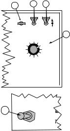
98-05018 |
TASC 6100 |
|
R2 |
||
|
turning on the Implement Status switch (closed circuit) the flow control valve is already open and product flow is instantaneous. This response assumes that some other device, such as a boom section valve, has stopped the product flow.
|
|
|
|
When the operator selects the "Close" condition, |
|
|
|
|
|
deactivation of the Implement Status Switch (open |
|
|
|
|
|
circuit) automatically causes the flow control valve to |
|
|
|
|
|
close. This response is preferred when it is necessary to |
|
|
|
|
|
use the flow control valve to stop the product flow. |
|
|
|
|
|
Use the following procedure to set the Status switch |
|
|
|
|
|
response. |
|
A-1 |
A-2 |
|
C |
A. Set the console to the following positions; |
|
|
|
|
|
|
|
ON |
OPERATE |
INC. |
1. Power |
ON |
|
OFF |
SETUP |
DEC. |
2. Mode Selector |
OPERATE |
|
|
% Rate |
A-3 |
3. Display Selector |
Total Applied |
|
Fan RPM |
Total Applied |
4. Boom switches |
OFF |
||
Product Vol. |
Application Rate |
|
|
||
Area |
|
|
Impl. Width |
(or Master switch) |
|
Speed |
|
|
Distance |
|
|
Scan |
PSI/Prime |
|
|
||
|
Test |
|
|
|
|
|
Speed |
|
|
|
|
|
|
DISPLAY SELECTOR |
|
|
|
B. Hold the INC./DEC. switch up to display the current |
||
|
|
|
|
|
|
|
|
|
1 2 3 4 5 6 7 8 9 |
|
|
setting (Hold or Close). Continuing to hold the INC. |
|||||
|
BOOMS |
|
|
|
switch up will cause the display to alternate |
|||
|
|
|
|
|
|
|
|
between the two options at about three to ten |
|
|
|
|
|
|
|
|
|
|
|
|
|
|
|
|
|
second intervals. The option appearing in the |
|
|
|
|
|
|
|
|
|
B |
MASTER |
|
|
|
display when the INC. switch is released is the |
|||
|
|
|
|
|
|
response selected. |
||
|
|
|
|
|
|
|||
|
|
|
|
|
|
|
|
|
|
|
ON |
|
MI |
|
|||
|
|
|
|
|
|
|
|
|
|
|
|
|
|
|
|
|
|
All Booms Off
When the operator selects a "Hold" condition, an “All Booms OFF" condition (either all Boom switches or the Master switch OFF) hold’s the flow control valve in its current position. When the boom valves are turned ON again the flow control valve is already open and product flow is instantaneous.
When the "Close" condition is selected, an “All Booms OFF" condition automatically causes the flow control valve to close. This response is preferred when it is necessary to use the flow control valve to stop the product flow.
CE&STANDARD VERSION |
2-8 |

TASC 6100 |
|
|
98-05018 |
|
|
R2 |
|
Use the following procedure to set the “All Booms OFF” |
|
|
|
A-1 |
A-2 |
C |
|
response. |
|
|
|
|
|
|
|
|
ON |
OPERATE |
INC. |
A. Set the console to the following positions; |
OFF |
SETUP |
DEC. |
1. Power |
ON |
|
|
|
% Rate |
|
|
A-3 |
||
|
Product Vol. |
|
Application Rate |
|||||||
|
|
|
|
|||||||
2. Mode Selector |
OPERATE |
Fan RPM |
|
|
|
Total Applied |
||||
|
Area |
|
|
|
Impl. Width |
|||||
3. Display Selector |
Impl. Width |
|
Speed |
|
|
|
Distance |
|
||
|
|
Scan |
Test |
PSI/Prime |
|
|||||
4. Boom switches |
OFF |
|
|
|
Speed |
|
|
|
|
|
|
DISPLAY SELECTOR |
|
|
|||||||
(or Master switch) |
1 |
2 |
3 |
4 |
5 |
6 |
7 |
8 |
9 |
|
|
||||||||||
BOOMS
B.Hold the INC./DEC. switch up to display the current setting (Hold or Close). Continuing to hold the switch up causes the display to alternate between the
two options at about three to ten second intervals. |
MASTER |
|
|
|
|
The option appearing in the display when the INC. |
B |
|
ON |
MI |
|
Switch is released is the response selected. |
|
|
SETTING THE GROUND SPEED OVERRIDE (GSO)
VALUE
To use the GSO feature, set the GSO value to the minimum ground speed you want to control to when the GSO switch is activated. This should be
the lowest speed at which the vehicle can dispense material satisfactorily. If you do not intend to use this feature, set this value to zero (0.0). (See page 1-7 for a more complete description of GSO operation.)
A-1 |
A-2 |
B |
|
||
|
|
ON OPERATE INC.
OFF |
SETUP |
DEC. |
Use the following procedure to set the GSO Speed.
|
|
|
% Rate |
|
|
|
|
|
Product Vol. |
Application Rate |
|
A. Set the console to the following positions; |
|
Fan RPM |
|
Total Applied |
|
A-3 |
Area |
|
Impl. Width |
||
|
|
|
Speed |
|
Distance |
|
|
|
Scan |
PSI/Prime |
|
1. Power |
ON |
|
Test |
|
|
|
Speed |
|
|||
|
DISPLAY SELECTOR |
||||
2. Mode Selector |
SET-UP |
|
1 2 3 4 5 |
6 |
7 8 9 |
3. Display Selector |
Speed |
|
|||
|
|
|
BOOMS |
|
|
B. Use the INC./DEC. switch to set the GSO speed to the
desired value. |
Mid-Tech |
|
Mid-Tech |
CAUTION: When traveling at a speed slower than the GSO speed setting, this feature will cause the product to be applied at a rate consistent with the GSO speed, rather than the true ground speed, possibly resulting in serious over application. When Ground Speed Override is being used, and the true ground speed is less
2-9 |
CE & StandardVersion |
Setup |
|
Cal |
|
|
. |
|
& |
|
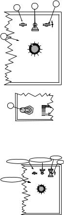
98-05018 |
|
TASC 6100 |
|
R2 |
|
||
than the pre-selected GSO Speed, the console will sound |
|||
|
|||
|
an alarm and the display will flash a “Too Slow” |
||
|
message to warn the operator of possible over applica- |
||
|
tion. |
||
|
PRODUCT VOLUME (FULL LOAD VALUE) |
||
A-1 |
A-2 |
C |
|
||
|
|
ON OPERATE INC.
OFF |
SETUP |
DEC. |
A-3 |
|
|
|
% Rate |
|
|
|
|
|
|
Product Vol. |
Application Rate |
|||||
|
Fan RPM |
|
|
Total Applied |
||||
|
|
Area |
|
|
Impl. Width |
|||
|
|
Speed |
|
|
Distance |
|
||
|
|
|
Scan |
|
PSI/Prime |
|
||
|
|
|
|
Test |
|
|
|
|
|
|
|
|
Speed |
|
|
|
|
|
|
DISPLAY SELECTOR |
|
|
||||
1 |
2 |
3 |
4 |
5 |
6 |
7 |
8 |
9 |
BOOMS |
|
|
|
|
|
|
||
Setting the Full Load Value
The Full Load Value of the vehicle can be preset into the console and automatically recalled when the vehicle is reloaded.
Use the following procedure to set the Full Load Value into the console.
A. Set the console to the following switch settings:
|
MASTER |
|
B |
|
|
OFF |
ON |
MI |
|
|
1. Power |
ON |
2. Mode Selector |
SET-UP |
3. Display Selector |
Product Vol. |
4. Boom switches |
OFF |
(or Master switch) |
|
|
|
|
Recall |
|
Recall & Set |
Recall & Set |
Set |
||
|
|
|
||
|
ON |
OPERATE |
INC. |
|
|
OFF |
SETUP |
DEC. |
|
Recall & Set
% Rate |
|
Product Vol. |
Application Rate |
Fan RPM |
Total Applied |
Area |
Impl. Width |
Speed |
Distance |
Scan |
PSI/Prime |
Test |
|
Speed |
|
DISPLAY SELECTOR
1 2 3 4 5 6 7 8 9
BOOMS
The display shows the current Full Load Value.
B.Use the INC./DEC. switch to set the desired Full Load Value.
Recalling the Full Load Value
When Product Vol. and OPERATE mode are selected, the Full Load Value of the vehicle can be recalled by holding the INC. switch up for at least three seconds.
Setting a Load Value Less than Full Load
If a full load is not taken aboard the vehicle, the actual amount loaded can be set without changing the Full Load Value. First recall the Full Load Value as explained in the previous section, then use the INC./DEC. switch to set the actual volume loaded into the tank.
CE&STANDARD VERSION |
2-10 |
 Loading...