


OPERATORS MANUAL
FOR THE
LH 4000 SPRAYER MONITOR
LH No. 020-183-UK Version 1.05
LH Technologies Denmark ApS
Mølhavevej 2
9440 Aabybro
Denmark
Tel. +45 9696 2500
Fax. +45 9696 2501
Internet: http://www.lh-agro.com/

LH 4000 OPERATORS MANUAL
2 |
LH AGRO |

|
LH 4000 OPERATORS MANUAL |
Contents |
|
INTRODUCTION ................................................................................................................. |
5 |
GENERAL USE ................................................................................................................... |
6 |
BEFORE USE ............................................................................................................. |
6 |
TRACTOR-INFO ..................................................................................................... |
6 |
CONTRAST ............................................................................................................ |
7 |
MEMORY-KEY........................................................................................................ |
7 |
TANK-FILL CONTROL............................................................................................ |
7 |
CLEAR-KEY............................................................................................................ |
7 |
SCREEN LIGHT...................................................................................................... |
7 |
NUMERIC KEYS..................................................................................................... |
7 |
THE DISPLAY......................................................................................................... |
8 |
BASIC "MENU"-SCREEN ....................................................................................... |
8 |
"STATUS" SCREEN ............................................................................................... |
9 |
SPRAY-PROGRAM............................................................................................................. |
9 |
SPRAYER, OPERATION................................................................................................... |
10 |
PRE-DEFINED FUNCTIONS .................................................................................... |
10 |
DOSAGE (APPLICATION).................................................................................... |
10 |
SPRAY-BOOM INDICATOR STATUS .................................................................. |
10 |
SPEED.................................................................................................................. |
10 |
OPERATOR SELECTABLE FUNCTIONS ................................................................ |
11 |
TRACTOR FUNCTIONS....................................................................................... |
11 |
SPRAY FUNCTIONS ............................................................................................ |
12 |
AREA FUNCTIONS .............................................................................................. |
14 |
TIME FUNCTIONS................................................................................................ |
14 |
SPRAY ENCODEMENTS.................................................................................................. |
15 |
DOSERATE............................................................................................................... |
15 |
DO’S AND DON’TS............................................................................................... |
15 |
STEP %..................................................................................................................... |
16 |
LITRE LEFT .............................................................................................................. |
16 |
HA LEFT.................................................................................................................... |
16 |
FLOW-FIGURE ......................................................................................................... |
16 |
FLOW CALIBRATION........................................................................................... |
16 |
BOOM WIDTH........................................................................................................... |
17 |
DRIVE FACTOR........................................................................................................ |
17 |
REGULATION DELAY .......................................................................................... |
17 |
UNIFORM PRESSURE............................................................................................. |
18 |
SPEED SENSOR (WHEEL TRACTOR, WHEEL SPRAYER) ................................... |
18 |
WHEEL TRACTOR ............................................................................................... |
18 |
WHEEL SPRAYER ............................................................................................... |
18 |
SPEED SENSOR CALIBRATION......................................................................... |
18 |
TANK VOLUME......................................................................................................... |
19 |
METRE SWITCH....................................................................................................... |
20 |
INPUT SET-UP ......................................................................................................... |
20 |
RPM SENSOR .......................................................................................................... |
20 |
WARNING ENCODE................................................................................................. |
20 |
LH AGRO |
3 |

LH 4000 OPERATORS MANUAL |
|
DATE-CLOCK ........................................................................................................... |
20 |
SPRAYER - DATA DELETE .............................................................................................. |
21 |
LOG BOOK........................................................................................................................ |
22 |
THE "LOG-BOOK", HOW TO USE THIS FEATURE................................................. |
22 |
START TASK ............................................................................................................ |
23 |
END TASK ................................................................................................................ |
24 |
SEE TASK................................................................................................................. |
25 |
DELETE TASK .......................................................................................................... |
25 |
EXITING "TASK-MODE" ........................................................................................... |
25 |
TANK FILL FEATURE ....................................................................................................... |
26 |
FILL-FLOWMETER CALIBRATION ...................................................................... |
27 |
OTHER IMPLEMENT ........................................................................................................ |
28 |
OTHER IMPLEMENT, OPERATION ................................................................................. |
29 |
SELECTABLE FUNCTIONS ..................................................................................... |
29 |
TRACTOR FUNCTIONS....................................................................................... |
29 |
AREA FUNCTIONS .............................................................................................. |
30 |
TIME FUNCTIONS................................................................................................ |
30 |
OTHER IMPLEMENT, ENCODE ....................................................................................... |
31 |
HA LEFT.................................................................................................................... |
31 |
WORKING WIDTH .................................................................................................... |
31 |
SPEED SENSOR. (WHEEL TRACTOR, WHEEL IMPLEMENT) .............................. |
32 |
WHEEL-TRACTOR............................................................................................... |
32 |
WHEEL IMPLEMENT ........................................................................................... |
32 |
SPEED SENSOR CALIBRATION......................................................................... |
32 |
IMPLEMENT SENSOR ............................................................................................. |
32 |
METRE-SWITCH ...................................................................................................... |
32 |
WARNING ENCODE................................................................................................. |
32 |
DATE/CLOCK ........................................................................................................... |
32 |
OTHER IMPLEMENT-DATA/DELETE............................................................................... |
33 |
LOG-BOOK........................................................................................................................ |
34 |
THE "LOG-BOOK", HOW TO USE THIS FACILITY ............................................. |
34 |
START TASK........................................................................................................ |
35 |
END TASK ............................................................................................................ |
36 |
SEE TASK............................................................................................................. |
37 |
DELETE TASK...................................................................................................... |
37 |
LEAVING "TASK-MODE"...................................................................................... |
37 |
SYSTEM MENU ................................................................................................................ |
38 |
TEST INPUT ......................................................................................................... |
39 |
TEST OUTPUT ..................................................................................................... |
40 |
SPEED SIMULATION ........................................................................................... |
40 |
SYSTEM DATA ......................................................................................................... |
40 |
ERROR-MESSAGES......................................................................................................... |
41 |
VOLTAGE WARNING........................................................................................... |
41 |
WARNING OUTPUT ............................................................................................. |
41 |
MEMORY-FAILURE.............................................................................................. |
41 |
MACHINE SETTING CHART ............................................................................................ |
42 |
NOTES .............................................................................................................................. |
43 |
4 |
LH AGRO |

LH 4000 OPERATORS MANUAL
INTRODUCTION
Congratulations with your new LH 4000 Spray Controller!
The product is a specifically developed spray controller based on the latest available technology. We are confident that it will serve you to your full satisfaction in the years to come.
The computer provides you with a comprehensive selection of valuable information’s not only when spraying, but in conjunction with all field work where its facilities for speed and area recording etc. may be desired.
We have endeavoured to deliver a fault free product. To ensure optimal use of the equipment we ask that great attention be paid when reading the manual. We are more than happy to help should any queries arise, both when the product is used for the first time and at any later date. Regarding responsibility for use of the product we refer to our sales and delivery terms especially paragraph 7, which follows:
7.Product usage.
7.1Any use of the product is at the sole risk of the buyer. The buyer is therefore not entitled to any form for compensation caused by, for example, any of the following:
!Disturbance to/from any electronic services or products that do not confirm to the standards for CE marking,
!Missing or poor signal coverage or a succession hereof from external transmitters/receivers, used by the buyer,
!Functional faults, which apply to or from a PC-program or PCequipment, not delivered by the seller,
!Faults that may arise from the buyers negligence to react to warnings and fault messages from the product, or which can be traced to negligence and/or absent constant control of the work carried out in comparison to the planned job.
7.2When implementing any new equipment the buyer must take great care and pay attention. Any doubts as to correct operation/use should result in contacting the sellers service department.
LH AGRO |
5 |
LH 4000 OPERATORS MANUAL
GENERAL USE
The LH 4000 is (specifically) designed for crop sprayer control.
The software design is consequently designed for easy use and access for the operator in conjunction with spray work.
The computer communicates with you through the screen in clear language.
Minimum use of this manual is therefore required.
BEFORE USE
It is essential that you make yourself familiar with the keys and their use. Please read carefully and study the following pages.
Unfold the back page, which shows the fascia of the computer.
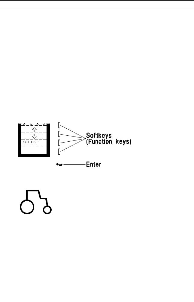
You communicate with the computer using only 5 keys.
You will appreciate that the screens relating to the four upper functionkeys (softkeys) change, as you proceed.
The screen shows the present significance of each individual key. The lower "enter/return-key" allows you to return to the previous screen.
TRACTOR-INFO
This key instantly displays:
ACTUAL SPEED
WORK EFFICIENCY
AREA WORKED
REMAINING AREA
6 |
LH AGRO |

LH 4000 OPERATORS MANUAL
CONTRAST
Adjustment of screen contrast. Can be useful when working under dark or sunny conditions.
NOTE! The screen may go dark in extreme hot or cold conditions. The display will return to normal when the working temperature of the monitor is back to normal.
To adjust the screen contrast; Use the +/- keys.
MEMORY-KEY
If you want an instant return to any screen, press this key before you scroll to another screen. The memokey allows for instant return to the memorised screen.
TANK-FILL CONTROL
This key activates the "FILL" feature, which is detailed later in this manual.
CLEAR-KEY
Only active in conjunction with encoding. Will erase any incorrectly entered figure.
SCREEN LIGHT
Switches the back-light on and off.
NUMERIC KEYS
Only active when encoding values, or when simulating forward speed.
|
|
|
|
|
|
LH AGRO |
7 |
|

LH 4000 OPERATORS MANUAL
THE DISPLAY
The screen is divided in two sections. The upper section is the information screen.
The lower relates to the softkeys.
THE INFO-SCREEN:
You will appreciate the information screen is designed by the manufacturer and cannot be altered by you.
THE LOWER (SOFTKEY) FUNCTIONSCREEN:
The actual significance of the four keys is displayed. You will notice that this status changes as you proceed. (see the following examples)
BASIC "MENU"-SCREEN
When powered up, the screen will light up and display the "main menu". Should you have selected an other screen, press the return-key until the "main menu" is displayed again:
SPRAYER
OTHER IMPLEMENT
SYSTEM
The "cursor" can be moved up & down using the softkeys. Place the cursor on the function you require and press "SELECT".
8 |
LH AGRO |

LH 4000 OPERATORS MANUAL
IMPORTANT! IMPORTANT! IMPORTANT!
The software program does not allow menu changes whilst the machine is moving.
This is to prevent operator mistakes and incorrect recordings.
"STATUS" SCREEN
Any time the "operation-menu" is selected, or you leave any encode menu, the status screen will appear. Here all the current encoded values will be shown. CHECK & ACCEPT the values before proceeding, by pressing the enter/returnkey.
NOTE! Before start remember to cancel (reset) all relevant counters. (Area-litre etc.) using the "DATA/DELETE" function, if required.
SPRAY-PROGRAM
From the basic menu, select sprayer:
Move cursor to "SPRAYER".
Press "SELECT".
From there you can choose:
OPERATION
ENCODE
DATA DELETE
LOG BOOK
LH AGRO |
9 |

LH 4000 OPERATORS MANUAL
SPRAYER, OPERATION
Two "Status screens" must be accepted. Press the "Return-key" until the following screen is displayed
PRE-DEFINED FUNCTIONS
DOSAGE (APPLICATION)
The primary function under sprayer is dosage. The dosage (application rate) is shown in Litres per Hectare, calculated as a result of the flow through the flowmeter, the speed and the recorded area. Subsequently no reading will show if the machine is stationary, or if there is no flow through the flowmeter.
Two arrows in the upper left corner of screen indicate the length and status of control signals to the pressure regulator.
NOTE! The shown application rate (L/Ha) is dependent of a correct calibration of wheel/ circumference/flow-figure/working width. (Details later in this manual).
SPRAY-BOOM INDICATOR STATUS
The number and position of active/inactive boom-sections is shown on the screen.
SPEED
The forward speed is displayed in km/h. (One decimal).
NOTE! Ensure you select the correct sensor. (Wheel tractor, Wheel sprayer) Radar is not available!
10 |
LH AGRO |
LH 4000 OPERATORS MANUAL
OPERATOR SELECTABLE FUNCTIONS
TRACTOR FUNCTIONS
METRE IN
TRACK: The distance recorded in the current track (tramline).
METRE: Recorded total metres
METRE START/
METRE STOP: Manual start/stop of distance counter.
BATT.: |
Battery voltage |
METRE IN TRACK:
The distance recorded in current track. You may use this function to locate a position in the track (e.g. the spot where the tank ran empty).
This function is related to the "REDUCE TRA. M." (This function is only visible whilst the sprayer is inactive.)
The "METRE IN TRACK"-counter is reset to NIL, each time the sprayer is shut
(e.g. at headlands).
However, should you shut the sprayer in a track, the computer memorises the distance driven! And displays "REDUCE TRA. M."
NOTE! Should you stop spraying at a position you would like to relocate, (E.g. if you need to refill your tank) Proceed thus:
After refilling your tank drive to start of track (headland border). Press "REDUCE TRA. M" and drive along the tramline. An audible and visual warning will be given 5 metres before the location at which the tank ran empty.
When the position is instruction is given to start spraying.
METRE.:
The total distance driven in metres.
This is measured with the wheel with the speed sensor fitted. You may choose "manual" start/stop of counter. Or automatically via the override sensor (sprayer main valve) switch. Select your mode in: "ENCODE" "METRE SWITCH".
or:
METRE START/ METRE STOP:
Manual Start/Stop of metre counter. The start/stop selection screen will only appear if “MANUAL” has been selected in “ENCODE”.
BATT.:
The current voltage of battery.
LH AGRO |
11 |

LH 4000 OPERATORS MANUAL
SPRAY FUNCTIONS
LITRE: Amount consumed from tank.
LITRE LEFT: Amount remaining in tank.
LITRE/MIN.: Litre consumption per minute.
LITRE: The total amount consumed since counter was reset. This function is a "trip-counter", which may be reset using the "DATA/DELETE" function. The "grand total" counter is also available in this menu.
LITRE LEFT: The amount of liquid in tank. However, this feature requires encoding the tank volume/amount filled, before starting. This is done in encode “LITRE LEFT”. This value is automatically entered is the optional tank fill feature is used.
LITRE/MIN.: The actual flow in Litres per minute through the flowmeter. Do not regard this as the Pump-capacity.
Pressing the "NEXT PAGE" key displays the next functions.
+xx %: Increase of application rate.
-xx %: Decrease of application rate.
DOSE-RATE/
NORMAL: Encodement of application rate, OR instant return to normal rate (+/- % activation)
+ xx %: Percentile increase of the application rate. You select the percent figure you require, in encode "STEP%"
- xx %: Percent decrease of application rate. (similar figure will be entered automatically, ref. the above).
NORMAL/
DOSAGE: Multifunctional softkey.
It will read "DOSE-RATE" normally. Select, and you will have instant access to enter or alter your desired application rate.
However, should you have activated either your "+" or "-" %- keys, the softkey will read "NORMAL". Subsequently, pressing this key will return your application rate to "normal" regardless what over/under rate you are currently applying.
12 |
LH AGRO |

LH 4000 OPERATORS MANUAL
Pressing the "NEXT PAGE" key displays the next functions.
+: Manual increase of pressure (application).
-: Manual decrease of pressure (application).
AUTO/MAN: Select automatic or manual application control. (+/- keys will appear when you select manual-mode
This facility may be used e.g. under severe field conditions where automatic (computer control) is inefficient, or you have observed abnormalities in the computer control mode.
NOTE! Be aware. Should you have selected "MANUAL" mode is the computer unable to resume to control before you reset to "AUTOMATIC" control mode
Pressing the "NEXT PAGE" key displays the next functions.
RPM: Shaft speed of an axle (only displayed if RPM ON is selected in encode).
LH AGRO |
13 |
LH 4000 OPERATORS MANUAL
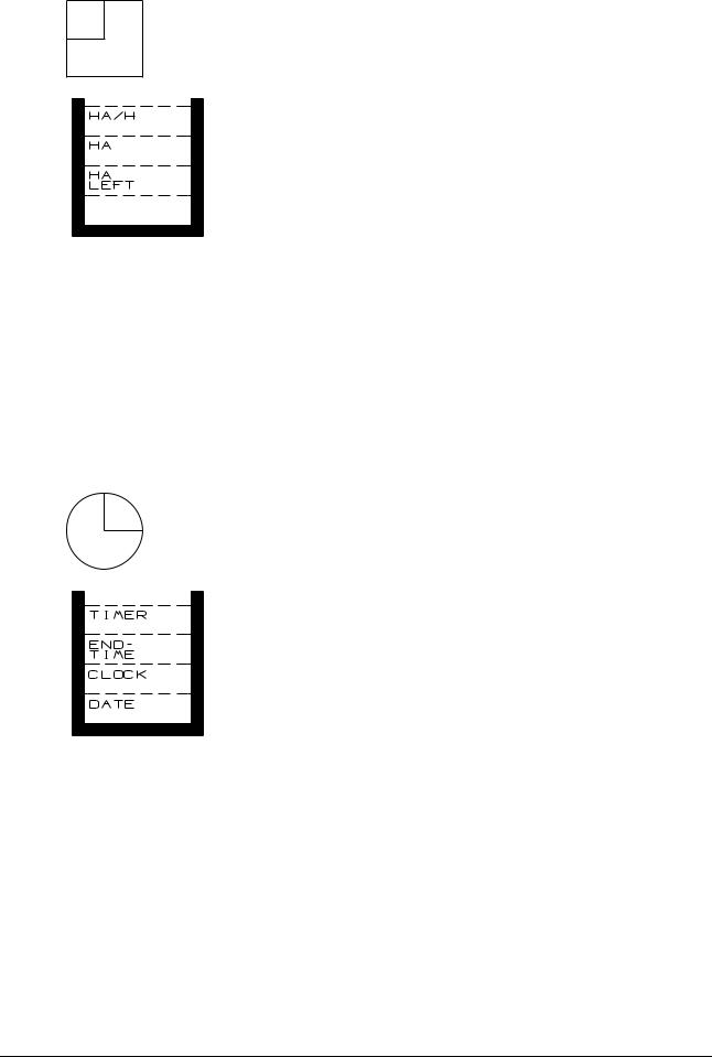
AREA FUNCTIONS
HA/H: Work efficiency.
HA: |
Area worked. |
HA LEFT: Remaining area.
HA/H: Work efficiency. The actual area capacity per hour.
HA: Area counter. The recorded area worked since reset of counter. May be reset in the "DATA/DELETE" menu. This is also where you will find the "Grand Total Area counter"
HA LEFT: Remaining area to work. This function requires encodement of actual size of the area in encode “HA LEFT”.
TIME FUNCTIONS
TIMER: Work hours/minutes.
END TIME: Expected time of finalisation.
CLOCK: |
Actual time. |
DATE: Day-month-year
TIMER: Records the work time on a specific job. You start and stop this recorder manually. May be reset in menu "DATA/DELETE", where the "Total time" recorder is also available.
END TIME: Expected time of day at which the job will be complete. Requires field size to be entered in encode “HA LEFT”.
CLOCK: Actual time. Time is adjusted in "ENCODE".
DATE: The actual date. The date is adjusted in "ENCODE".
14 |
LH AGRO |
 Loading...