


 Spraying Systems Co.®
Installation,
Programming
and Operating
Manual

Cable Connections
BATTERY
BATTERY
CABLE
844 SPRAYER CONTROL
BATTERY
CABLE
LEAD
FLOW METER (OPTION 1)
PRESSURE TRANDUCER (OPTION 2)
SENSOR END
CABLE
SPEED
SENSOR
SENSOR
CABLE
LEAD
PRESSURE
REGULATING
VALVE
VALVE
CABLE LEAD
VALVE END
CABLE
BOOM
CONTROL VALVES

Table of Contents
Introduction |
2 |
|
Sprayer Control Installation |
4 |
|
Mounting Sprayer Components |
4 |
|
|
Pressure Regulator in Bypass Mode |
4 |
|
Pressure Regulator in Throttling Mode |
5 |
|
Flow meter |
6 |
|
Boom Control Valves |
6 |
|
Pressure Transducer |
6 |
Installing the Speed Sensor Assembly |
7-9 |
|
Mounting the TeeJet 844 Console |
10-12 |
|
Connecting System Components to the Control Console |
13 |
|
Component Wiring |
14-15 |
|
Programming Guidelines |
16 |
|
Steps to Successful Programming |
17 |
|
System Setup Mode |
17 |
|
Programming Steps |
|
|
1 |
Setting the Program Mode - U.S./Turf/NH3/Imperial/S.I. |
17 |
2 |
Flow meter or Pressure Based |
17 |
3 |
Flow meter Pulses |
18 |
4 |
Pressure Transducer Maximum Rating (P Hi) |
18 |
5 |
Pressure Transducer Low Pressure Calibration (P rEF) |
19 |
6 |
Nozzle Spacing |
19 |
7 |
Number of Spray Tips Per Boom Section |
20 |
8 |
User Programmable Tip |
20 |
9 |
Pressure Regulating Mode |
21 |
10 |
Regulation Adjustment Speed |
22 |
11 |
Boom Control Valve Type |
22 |
12 |
Recording Speed Sensor Magnetic Pulses |
23-24 |
|
Radar Speed Sensor Pulses |
|
13 |
Distance Counter |
24 |
14 |
Simulated Ground Speed |
24 |
15 |
Liquid Specific Gravity |
25 |
16 |
Communications |
25 |
17 |
Minimum Regulating Pressure Setting |
26 |
Application Setup Mode |
27 |
|
Programming Steps |
|
|
1 |
Target Application Rate |
27 |
2 |
Nozzle Selection |
27-28 |
3 |
Calculation Step |
28-29 |
Operating Instructions |
|
|
Sprayer Checkout |
30 |
|
The Spraying Operation |
31 |
|
Features |
|
|
Boost Mode |
32 |
|
Area/Volume Feature |
32 |
|
Flow Rate Feature |
33 |
|
Application Alarm |
33 |
|
No Flow Alarm |
33 |
|
Printing |
|
34 |
Troubleshooting Guide |
35-37 |
|
Flow meter Calibration |
38-39 |
|
Terms and Conditions of Sale |
40 |
|
TeeJet is a registered trademark of
Spraying Systems Co.
1

Introduction
The TeeJet® 844 Sprayer Control package for pressure based systems could consist of the components shown in this photograph.
They include:
(1)Computerized Control Console
(2)Pressure Regulating Valve
(3)Connecting cables, plugs, and cable ties
(4)Pressure Transducer
(5)Speed Sensor Kit – Magnetic type
(6)TeeJet Agricultural Spray Products Catalog (not shown)
(7)844 Mini Manual (not shown)
Congratulations! And thank you for choosing Spraying Systems’ advanced 844 sprayer control system. With its proper installation and maintenance, you can enjoy many seasons of accurate and uniform spray application with fingertip convenience and ease of operation.
Installation and Programming of your control system will be covered in easy- to-follow, step-by-step instructions.
WE RECOMMEND THAT YOU READ THESE INSTRUCTIONS COMPLETELY before attempting installation and programming of your 844 sprayer control. The unit’s performance will depend on its proper installation and programming, along with planned preventive maintenance of your entire sprayer.
PRESSURE
REGULATING
VALVE
COMPUTERIZED
CONTROL CONSOLE
PRESSURE
TRANSDUCER
CONNECTING
CABLES,
PLUGS AND
CABLE TIES
SPEED SENSOR KIT
2

The TeeJet® 844 Sprayer Control basic package for flow based systems could consist of the components shown in this photograph.
They include:
(1)Computerized Control Console
(2)Pressure Regulating Valve
(3)Connecting cables, plugs, and cable ties
(4)Flow meter
(5)Speed Sensor Kit – Magnetic type
(6)TeeJet Agricultural Spray Products Catalog (not shown)
(7)844 Mini Manual (not shown)
PRESSURE
REGULATING
VALVE
COMPUTERIZED
CONTROL CONSOLE
CONNECTING
CABLES,
PLUGS AND
CABLE TIES
FLOW METER
SPEED SENSOR KIT
NOTE: The 844 Sprayer Control is fully capable of operating and controlling NH3 applications. However, hardware components such as flow meters, regulating valves, and cooling towers will vary from the Standard Kit. A complete TeeJet NH3 Hardware Kit is available through your TeeJet dealer. The 844 is also compatible with other NH3 systems currently on the market. Contact your TeeJet dealer for more information.
3

Mounting Sprayer Components
PRESSURE REGULATOR IN BYPASS MODE
All pressure regulating valves for the 844 will be wired for use in a by-pass system. While plumbed in a by-pass mode, with the Auto/Man key in the “MAN” mode, the valve should close when the  key is depressed and open when the
  key is depressed.
The pressure regulating valve can also be mounted in a throttling situation as an alternative location. Refer to page 5, and Figures 8 and 8A.
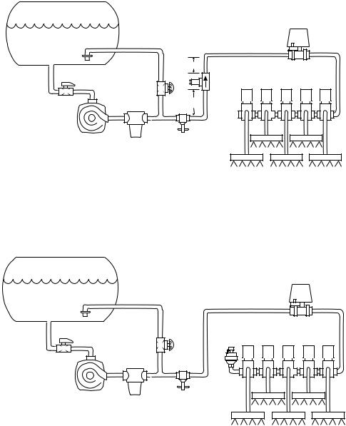
NOTE: The diagrams in Figures 7, 7A, 8 and 8A are shown as general guidelines to follow when plumbing 844 components. The type of pump used and location of other components can vary from sprayer to sprayer. It is important to ensure that if a pressure transducer is used that it is located as close to the spray tips as possible. Normally this is at the boom control valves. However, if one particular boom section is always used, the pressure transducer can be mounted on that particular boom section. If a flow meter is used, ensure that all of the flow going through the flow meter is directed to the spray tips. Make sure that proper distance is allowed on the inlet and outlet side of the flow meter (refer to figures 7A and 8).
TANK |
|
FIGURE 7 |
|
|
|
BYPASS PLUMBING DIAGRAM |
|
JET AGITATOR |
|
PRESSURE BASED SYSTEM |
|
|
|
||
|
DIAPHRAGM |
AGITATOR |
|
TANK SHUT-OFF |
PUMP |
||
VALVE |
|||
|
|||
|
|
PRESSURE |
|
|
|
TRANSDUCER |
|
STRAINER |
|
ELECTRIC |
|
|
|
BALL VALVES |
|
PRESSURE RELIEF VALVE |
|
||
PRESSURE |
|
REGULATING |
BOOM SECTIONS |
VALVE |
TANK
JET AGITATOR |
FIGURE 7A |
|
|
BYPASS PLUMBING DIAGRAM |
|
DIAPHRAGM |
FLOW BASED SYSTEM |
|
PUMP |
AGITATOR |
|
TANK SHUT-OFF |
||
|
VALVE |
|
STRAINER |
ELECTRIC |
|
BALL VALVES |
||
|
PRESSURE RELIEF VALVE 


PRESSURE
REGULATING
VALVE
5-7” 
(12-17 CM)
10-12”
(25-35 CM)
FLOW METER
BOOM SECTIONS
4
PRESSURE REGULATOR IN
THROTTLING MODE
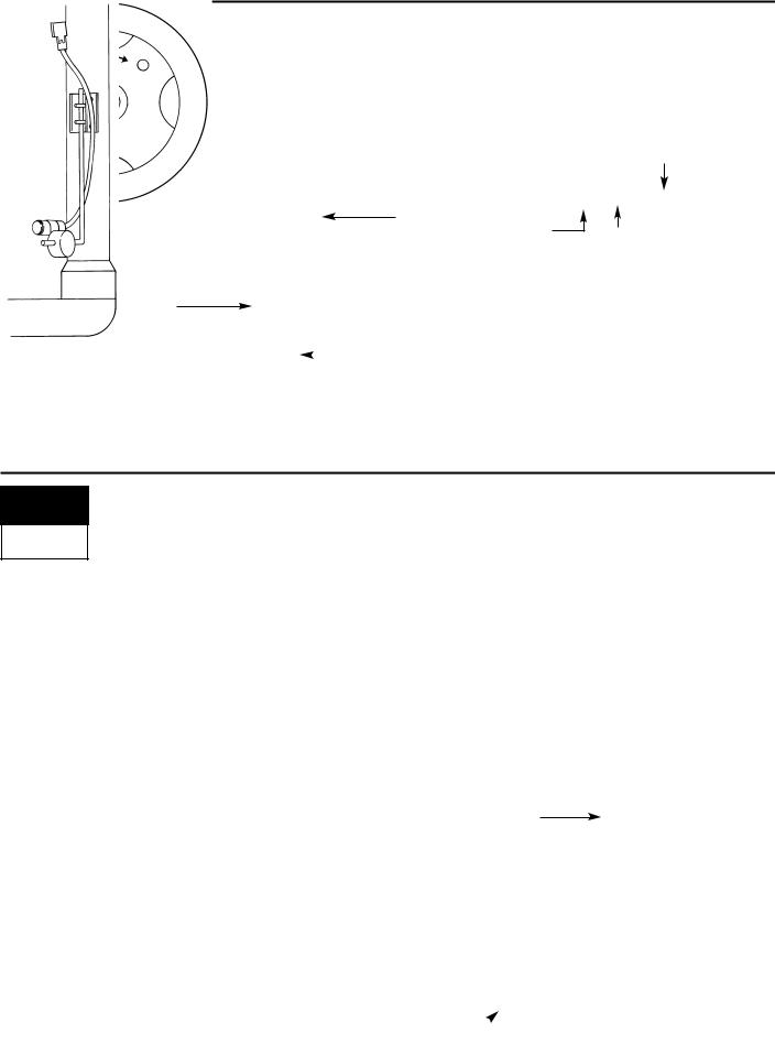
In large flow situations, the pressure regulating valve, as shown in Figures 8 and 8A, can be located in the supply line before the boom control valves. If you choose this location, the 844 will need to be properly programmed to reverse the polarity of the valve. This step can be found in the System Setup instructions on page 21. When in throttling mode, the valve should open when the  key is depressed, and close when the
  key is depressed. Be sure to check this before plumbing the valve into the system.
PRESSURE
TANK REGULATING
VALVE
JET AGITATOR
5-7”
(12-17 CM)
TANK SHUT-OFF |
SOLENOID VALVES |
FLOW METER |
|
AGITATOR |
|
VALVE |
|
10-12” |
|
(25-35 CM) |
|
CENTRIFUGAL
PUMP
THROTTLING
STRAINER VALVE
BOOM SECTIONS
FIGURE 8
THROTTLING PLUMBING DIAGRAM
FLOW BASED SYSTEM
PRESSURE
TANK REGULATING
VALVE
JET AGITATOR |
|
TANK SHUT-OFF |
|
AGITATOR |
SOLENOID VALVES |
VALVE |
|
CENTRIFUGAL |
|
PUMP |
PRESSURE |
|
TRANSDUCER |
STRAINER |
THROTTLING |
VALVE |
|
|
BOOM SECTIONS |
FIGURE 8A
THROTTLING PLUMBING DIAGRAM
PRESSURE BASED SYSTEM
5

FLOW METER
To ensure accurate readings, the flow meter (if used) must be mounted 10˝to 12˝ (25-35 cm) from other pipe fittings, preferably in a vertical position with the flow going up. It should also be mounted with direction of flow arrow pointing toward the boom control valves. Refer to Figures 7A and 8.
Be sure the flow meter is plumbed so that all liquid passing through it is routed to the booms and not back to the tank. When using three-way boom control valves, refer to page 22 of this manual for programming guidelines.
BOOM CONTROL VALVES
The Boom Control Valves are connected in tandem and centered in front of the boom sections. See the Control Valve Instruction Manual for mounting instructions. If using three-way valves, refer to the instruction manual of the valves you are using for valve calibration instructions.
PRESSURE TRANSDUCER
The pressure transducer (if used) should be installed as close to the spray tips as possible. Normally this is at the boom control valve assembly. Refer to pages 4 and 5, Figures 7 and 8A. Mount the unit vertically on a short stand pipe to help protect the sensor.
NOTE: Pressure drop, to some degree, is found in most plumbing systems. Pressure drop is created when there is any kind of restriction in the spray line reducing flow rate and is quite often produced between the boom control valve assembly and the spray tips. If one of the boom sections on the sprayer is always used, the pressure transducer can be installed on that particular boom section, therefore minimizing any potential pressure drops between the sensor and spray tips. If the pressure drop in your system is greater than 5 psi (0.3 bar), you should consider this as an alternative location for the pressure transducer.
Check all components to make sure they are mounted securely to avoid excessive vibration.
6
Installing the Speed Sensor Assembly
Components: Two magnets, Sensor with attached connector cable, and mounting hardware.
If you are installing a radar ground speed sensor, follow the instructions supplied with that unit.
SPEED
STE P
1
Location
The speed sensor assembly should be installed on a non-driven wheel to avoid potential errors that are likely to occur from a slipping drive wheel. Refer to Figure 1.
Proximity Sensor (optional)
An optional proximity sensor is available to use in cases where space
is limited or for drive shaft mounting.
MAGNET
The proximity sensor will work by sensing any metal object. The proximity sensor must be mounted so that the sensor face is within 1/8 to 3/8 inch (3-10 mm) of the metal object being read.
RIM
CABLE
 SENSOR
FIGURE 1
WHEEL MOUNTING
OF MAGNETIC
SPEED SENSOR
 TIRE
TIRE
NOTE:
TARGET FACES
TIRE LUGS
FIGURE 2
7
SPEED
STE P
2
Installing the Wheel Magnets
Check for pre-drilled holes in the wheel rim. If pre-drilled holes are not available, layout a pattern as shown in Figure 4 and drill two 3/8 inch (10 mm) holes, locating them near the outer edge of the rim, if possible and 180° from each other.
Place the magnets into each of the two holes on the inside rim and securely fasten using the nuts and washers provided.
MAGNET
NUT 
WHEEL
WASHER |
NUT |
|
3/8˝(10 mm) HOLE FOR MAGNET
|
|
TIRE |
|
|
|
FIGURE 4 |
FIGURE 5 |
|
MAGNET LOCATIONS |
MAGNET ASSEMBLY |
|
SPEED
STE P
3
FIGURE 6
SENSOR MOUNTING
Installing the Magnetic Sensor
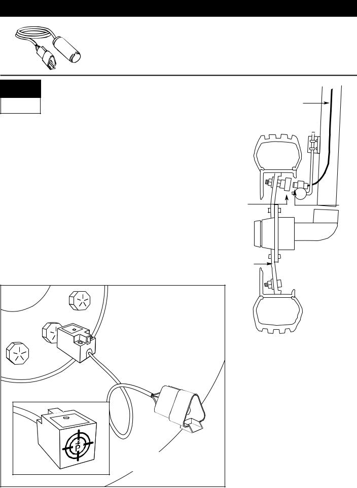
The flat, pressed L bracket of the wheel speed sensor kit should be secured to a vertical member near the non-driven wheel. The round, right angle steel bracket is then secured to the flat bracket with the two U-bolts and necessary hardware provided. The round, right angle bracket is then used to secure the magnetic sensor mounting clamp.
The magnetic sensor should be inserted into the mounting clamp and positioned to within 1/8 to 3/8 inch (3-10 mm) of the wheel magnet. Tighten the sensor clamp using the clamp screw per Figure 6A.
Your installation will likely vary from the example. It may be necessary to customize the installation to accommodate your specific machine. Keep in mind that the two magnets must be spaced an equal distance around the wheel. The magnetic sensor
with the magnets and positioned 3/8 inch (3-10 mm) from each
pass the Sensor assembly.
FLAT
L BRACKET
FIGURE 6A
SENSOR ASSEMBLY
 BRACKET
SENSOR 
SENSOR 
CLAMP
SCREW
8
SPEED
STE P
4
Confirming Speed Sensor Installation
Magnetic Wheel Sensor:
After your wheel or proximity sensor is installed and once the 844 console is installed and powered up, you can test the speed sensor installation. Connect the wheel speed or proximity sensor to the sensor cable, and in turn connect the sensor cable to the 844 console. When the connection is made, rotate the wheel on which the magnets are installed. If using a proximity sensor, you will be sensing metal objects and not magnets. Each time a magnet (metal object for proximity sensor) passes the sensor a red LED (orange LED for proximity sensor) on the back of the sensor will light. The LCD display on the console will also indicate a speed as the sensor receives and sends electronic pulses.
Radar:
If you are using a radar speed sensor it should be connected to the speed sensor connector on the sensor end cable. An adapter cable will be necessary when using most radars and are available through your TeeJet 844 dealer. The 844 will automatically sense if the speed sensor is a wheel speed or proximity type or radar type sensor during calibration. The 844 is automatically adapted to most brands of radar speed sensors, provided that the appropriate adapter cable is used. If using a radar sensor, the 844 will display rAd during the calibration procedure.
9

MOUNTING THE TEEJET 844 CONSOLE
CONSOLE
STE P
1
Location
Determine the best location for the control console in the cab or operator’s compartment. Allow sufficient clearance, approximately 4-5˝(10-12 cm) to accommodate for the power and operating cables that will be connected to the cable leads and connectors on the right side of the console.
CONSOLE
STE P
2
Mounting
Mount the console to a firm support within the cab area, and secure using the slots provided on the top, back, or bottom of the Console. Although two simple brackets are supplied with the unit, some additional bracketing may be necessary. The slots in the 844 will accept 1/4˝(6 mm) bolts.
BRACKETS PROVIDE ANGLE ADJUSTMENT
10

CONSOLE
STE P
3
BATTERY
Power Connection
Locate the power cable which has a black connector on one end, and two battery terminal rings on the other. Extend the battery terminal ring end of this cable from the cab to the battery.
Note: Some tractors use two 6 Volt batteries as a power source. Make sure there is a total of 12 Volts delivered to the controller by connecting to the
(+) terminal on one battery and the (-) terminal on the other battery.
Reliable operation of the 844 Sprayer Control depends on a clean power supply. Ensure this by connecting the power cables directly to the battery and not to another power source.
Connect the battery terminal rings to the battery posts, making sure that the positive (red) and negative (black) wires correspond with the polarity of the battery terminals.
Note: The power cable is designed to provide the simple addition of a remote master boom switch in a convenient location (i.e. on the throttle, gear shift, or floor switch). To install a remote boom switch, simply install a switch in the loop of brown wire in the power cable. The switch should be rated to handle the total current used by all boom section valves combined. If installed, the remote master switch will operate in series with the boom switches on the console.
Connect the battery cable to the console by joining its connector with the connector on the short power cable lead that extends from the middle of the right side of the console.
Test the installation by depressing the  key once to turn the 844 console on. If the display shows information, you have wired the power correctly.
Note: The TeeJet 844 Sprayer Control has an automatic power down feature. With the master boom switch in the “off” position, the 844 will automatically shut down after 10 minutes of no inputs. This prevents possible battery drainage. To turn the console “off” with the Master Switch located in the “off” position, depress and hold the  key while depressing the
  key once, and then releasing both keys. The console display will read “OFF” and will shut down after 5 seconds providing no other keys are depressed.
|
CONSOLE |
RED (POS.) |
CONSOLE |
RED (POS.) |
|
BATTERY |
|
|
BATTERY |
|
WIRES |
|
WIRES |
|
|
|
|
BLACK (NEG.) |
|
BLACK (NEG.) |
|
|
|
|
|
24-VOLT SYSTEM USING |
|
ONE 12-VOLT BATTERY |
|
TWO 12-VOLT BATTERIES |
|
RED (POS.) |
CONSOLE |
|
CONSOLE |
|
BATTERY |
RED (POS.) |
BATTERY |
|
WIRES |
|
WIRES |
BLACK (NEG.) |
BLACK (NEG.) |
||
|
|
||
12-VOLT SYSTEM USING |
|
12-VOLT SYSTEM USING |
|
TWO 6-VOLT BATTERIES |
|
TWO 6-VOLT BATTERIES |
|
11
CONSOLE
STE P
4
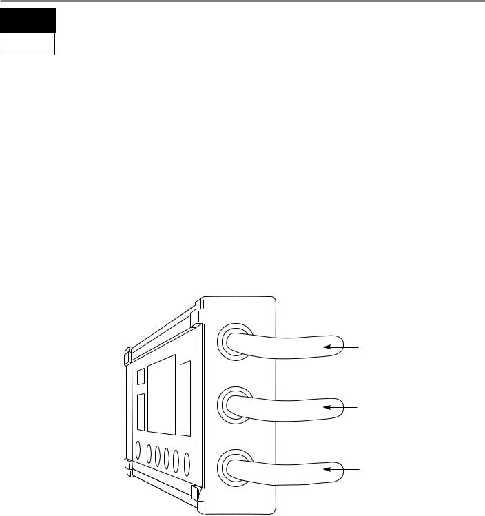
Connecting Component Cables to Console
Now that you have the console installed you can begin connecting it to the other components of the 844 system. The standard kit contains a valve end cable that attaches to the boom control valves and the pressure regulating valve on one end, and directly to the lower right cable lead of the 844 on the other end. The valve end cable can be identified as the one with a single connection plug on one end and either 5 or 7 single wires and one small two wire connector on the valve end.
A second cable connects the flow meter and/or pressure sensor, and a magnetic wheel speed sensor, proximity speed sensor or radar speed sensor to the 844 console. It attaches to the sensor cable connector located on the top of the right side of the controller. The correct cables will be supplied with the 844 kit you ordered or purchased.
Lay out the cables before installing the sprayer components to be sure the cables are long enough. Each of these cables is 15 feet (4.5 meters) in length from the sensor connections to the 844 console connection. If your installation requires longer cables, an 8 or 15 foot (2.5 or 4.5 meter) extension that installs between the console and the standard end cable is available.
If an exit hole had to be cut in the cab, be sure the edges are deburred and protected to prevent damage to the cables.
SENSOR CABLE
LEAD
POWER CABLE
LEAD
VALVE CABLE
LEAD
12
 Loading...