


CenterLine
Software Version 2.02
Copyrights
© 2007 TeeJet Technologies Inc. All rights reserved. No part of this document or the computer programs described in it may be reproduced, copied, photocopied, translated, or reduced in any form or by any means, electronic or machine readable, recording or otherwise, without prior written consent from TeeJet Technologies, Inc.
Trademarks
Unless otherwise noted, all other brand or product names are trademarks or registered trademarks of their respective companies or organizations.
Limitation of Liability
TEEJET TECHNOLOGIES, INC. PROVIDES THIS MATERIAL “AS IS” WITHOUT WARRANTY OF ANY KIND, EITHER EXPRESSED OR IMPLIED. NO COPYRIGHT LIABILITY OR PATENT IS ASSUMED. IN NO EVENT SHALL TEEJET TECHNOLOGIES, INC. BE LIABLE FOR ANY LOSS OF BUSINESS, LOSS OF PROFIT, LOSS OF USE OR DATA, INTERRUPTION OF BUSINESS, OR FOR INDIRECT, SPECIAL, INCIDENTAL, OR CONSEQUENTIAL DAMAGES OF ANY KIND, EVEN IF TEEJET TECHNOLOGIES HAS BEEN ADVISED OF SUCH DAMAGES ARISING FROM TEEJET SOFTWARE.

TABLE OF CONTENTS
CHAPTER 1 - INTRODUCTION . . . . . . . . . . . . . . . . . . . . . . . . . . . . . . . 1
STRAIGHT OR CURVED GUIDANCE . . . . . . . . . . . . . . . . . . . . . . . . . . . . . . . . . . . . 1 WIRELESS REMOTE CONTROL UNIT . . . . . . . . . . . . . . . . . . . . . . . . . . . . . . . . . . . 1 LIGHTBAR DISPLAY . . . . . . . . . . . . . . . . . . . . . . . . . . . . . . . . . . . . . . . . . . . . . . . . . 1 MENU ITEMS AND PICK LIST TEXT . . . . . . . . . . . . . . . . . . . . . . . . . . . . . . . . . . . . 1
Wireless Remote Control . . . . . . . . . . . . . . . . . . . . . . . . . . . . . . . . . . . . . . . . . . . . . . . . . . 3
LIGHTBAR . . . . . . . . . . . . . . . . . . . . . . . . . . . . . . . . . . . . . . . . . . . . . . . . . . . . . . . . . 4 FCC STATEMENT . . . . . . . . . . . . . . . . . . . . . . . . . . . . . . . . . . . . . . . . . . . . . . . . . . . 4
CHAPTER 2 - SETUP . . . . . . . . . . . . . . . . . . . . . . . . . . . . . . . . . . . . . . . 5
QUICK START GUIDE . . . . . . . . . . . . . . . . . . . . . . . . . . . . . . . . . . . . . . . . . . . . . . . . 5
First Time Start-Up Sequence . . . . . . . . . . . . . . . . . . . . . . . . . . . . . . . . . . . . . . . . . . . . . . 5 Typical Start-Up Sequence . . . . . . . . . . . . . . . . . . . . . . . . . . . . . . . . . . . . . . . . . . . . . . . . 5
CENTERLINE SETUP . . . . . . . . . . . . . . . . . . . . . . . . . . . . . . . . . . . . . . . . . . . . . . . . 7
Guidance Mode . . . . . . . . . . . . . . . . . . . . . . . . . . . . . . . . . . . . . . . . . . . . . . . . . . . . . . . . . 7 Lightbar . . . . . . . . . . . . . . . . . . . . . . . . . . . . . . . . . . . . . . . . . . . . . . . . . . . . . . . . . . . . . . 15 System Setup . . . . . . . . . . . . . . . . . . . . . . . . . . . . . . . . . . . . . . . . . . . . . . . . . . . . . . . . . . 19
TOOLS . . . . . . . . . . . . . . . . . . . . . . . . . . . . . . . . . . . . . . . . . . . . . . . . . . . . . . . . . . . 23
Receiver . . . . . . . . . . . . . . . . . . . . . . . . . . . . . . . . . . . . . . . . . . . . . . . . . . . . . . . . . . . . . . 24 Lightbar . . . . . . . . . . . . . . . . . . . . . . . . . . . . . . . . . . . . . . . . . . . . . . . . . . . . . . . . . . . . . . 24 Level . . . . . . . . . . . . . . . . . . . . . . . . . . . . . . . . . . . . . . . . . . . . . . . . . . . . . . . . . . . . . . . . . 24 e-Dif . . . . . . . . . . . . . . . . . . . . . . . . . . . . . . . . . . . . . . . . . . . . . . . . . . . . . . . . . . . . . . . . . 24 e-Dif Info . . . . . . . . . . . . . . . . . . . . . . . . . . . . . . . . . . . . . . . . . . . . . . . . . . . . . . . . . . . . . . 25 Demo . . . . . . . . . . . . . . . . . . . . . . . . . . . . . . . . . . . . . . . . . . . . . . . . . . . . . . . . . . . . . . . . 25 Next . . . . . . . . . . . . . . . . . . . . . . . . . . . . . . . . . . . . . . . . . . . . . . . . . . . . . . . . . . . . . . . . . 25 To Start . . . . . . . . . . . . . . . . . . . . . . . . . . . . . . . . . . . . . . . . . . . . . . . . . . . . . . . . . . . . . . . 25
CHAPTER 3 - OPERATION . . . . . . . . . . . . . . . . . . . . . . . . . . . . . . . . . 27
OPERATION MENU . . . . . . . . . . . . . . . . . . . . . . . . . . . . . . . . . . . . . . . . . . . . . . . . . 27
New? Resume? . . . . . . . . . . . . . . . . . . . . . . . . . . . . . . . . . . . . . . . . . . . . . . . . . . . . . . . . 27 Apply On/Off . . . . . . . . . . . . . . . . . . . . . . . . . . . . . . . . . . . . . . . . . . . . . . . . . . . . . . . . . . . 28 Return To Point . . . . . . . . . . . . . . . . . . . . . . . . . . . . . . . . . . . . . . . . . . . . . . . . . . . . . . . . 30
HEADLAND GUIDANCE . . . . . . . . . . . . . . . . . . . . . . . . . . . . . . . . . . . . . . . . . . . . . 30
Reference Guideline . . . . . . . . . . . . . . . . . . . . . . . . . . . . . . . . . . . . . . . . . . . . . . . . . . . . . 31 Switching From Headland To Straight-Line Guidance . . . . . . . . . . . . . . . . . . . . . . . . . . . 31 Headland Guidance Lightbar Graphics . . . . . . . . . . . . . . . . . . . . . . . . . . . . . . . . . . . . . . 32
STRAIGHT-LINE GUIDANCE . . . . . . . . . . . . . . . . . . . . . . . . . . . . . . . . . . . . . . . . . 33
Curved AB Guidance . . . . . . . . . . . . . . . . . . . . . . . . . . . . . . . . . . . . . . . . . . . . . . . . . . . . 34
APPLIED AREA DETECTION . . . . . . . . . . . . . . . . . . . . . . . . . . . . . . . . . . . . . . . . . 35
Applied Area Detection . . . . . . . . . . . . . . . . . . . . . . . . . . . . . . . . . . . . . . . . . . . . . . . . . . . 35 Neighboring Swath Detection . . . . . . . . . . . . . . . . . . . . . . . . . . . . . . . . . . . . . . . . . . . . . . 36
LIGHTBAR INDEX . . . . . . . . . . . . . . . . . . . . . . . . . . . . . . . . . . . . . . . . . . . . . . . . . . 36 SWATH MANAGER 5 . . . . . . . . . . . . . . . . . . . . . . . . . . . . . . . . . . . . . . . . . . . . . . . 39
Installation . . . . . . . . . . . . . . . . . . . . . . . . . . . . . . . . . . . . . . . . . . . . . . . . . . . . . . . . . . . . 39
TILT COMPENSATION MODULE . . . . . . . . . . . . . . . . . . . . . . . . . . . . . . . . . . . . . . 41
Tilt Compensation Module Installation . . . . . . . . . . . . . . . . . . . . . . . . . . . . . . . . . . . . . . . 42
EXITING OPERATION . . . . . . . . . . . . . . . . . . . . . . . . . . . . . . . . . . . . . . . . . . . . . . . 43
CenterLine 2.02 i
98-05054 R6

ii

CHAPTER 1 - INTRODUCTION
CenterLine is an economical lightbar guidance system that is controlled by a wireless remote. CenterLine provides accurate Straight-Line and Curved Guidance for use in spraying, seeding, and other related jobs at a cost that rivals foam markers. The CenterLine product is equipped with a combination Beacon/WAAS or WAAS only DGPS receiver, providing sub-meter, pass-to-pass positioning accuracy. The wireless remote control is used to configure and operate the system through menus and options displayed on the lightbar.
CenterLine’s attractive design combines compact size with fully adjustable, easy to see LEDs. Using dedicated buttons on the wireless remote, the lightbar can be dimmed to efficiently run at night and brightened for viewing in full sunlight.
STRAIGHT OR CURVED GUIDANCE
CenterLine guides along various types of swaths with sub-meter, pass-to-pass accuracy. Select the driving pattern and CenterLine determines the closest swath to follow. There is no need to decide a guidance pattern ahead of time or commit to a pattern for the entire job. CenterLine allows the switching of patterns during operation, determining when a new pattern is being used and keeping the operator informed of the current status.
WIRELESS REMOTE CONTROL UNIT
CenterLine’s ergonomic, handheld remote control is easier to use than most television remotes. Seven easy-to-read buttons allow for the scrolling of menus displayed on the lightbar. The remote keypad is backlit for nighttime operation. Three AAA batteries (included) power the unit for an entire season.
The small, powerful remote permits mounting the weather-resistant lightbar outside on the hood or in the cab. When mounted outside, wireless communication permits easy operation while the cab stays clean and sealed from dust and contaminants.
LIGHTBAR DISPLAY
A text display on the lightbar reports a choice of guidance information. It also warns when an area of the field is entered that has already been applied. Guidance text information can be turned off, if preferred. Two of the following guidance messages are available for selection during operation to monitor progress:
•Cross-Track Error
•Current Swath Number
•Vehicle Speed
•Applied Area
•Vehicle Course On Ground (COG)
MENU ITEMS AND PICK LIST TEXT
Throughout this User’s Guide, menu item text is displayed between < > characters (i.e., <START>). Buttons on the remote control are denoted in italics (i.e., Arrow buttons) and will be displayed in the margin of the User’s Guide.
Most of the figures in this guide are menu items that are displayed in the text window of the lightbar. This text represents either a menu item, such as <GUIDANCE>, or a list item, such as <METRIC>.
Arrow buttons
CenterLine 2.02 1
98-05054 R6
The lightbar text window can display a single line of text up to ten characters in length. Figure 1-1 illustrates an example of a single text line that would be displayed on the lightbar.
Figure 1-1: Example of Lightbar Text Display
Start
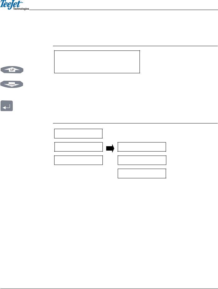
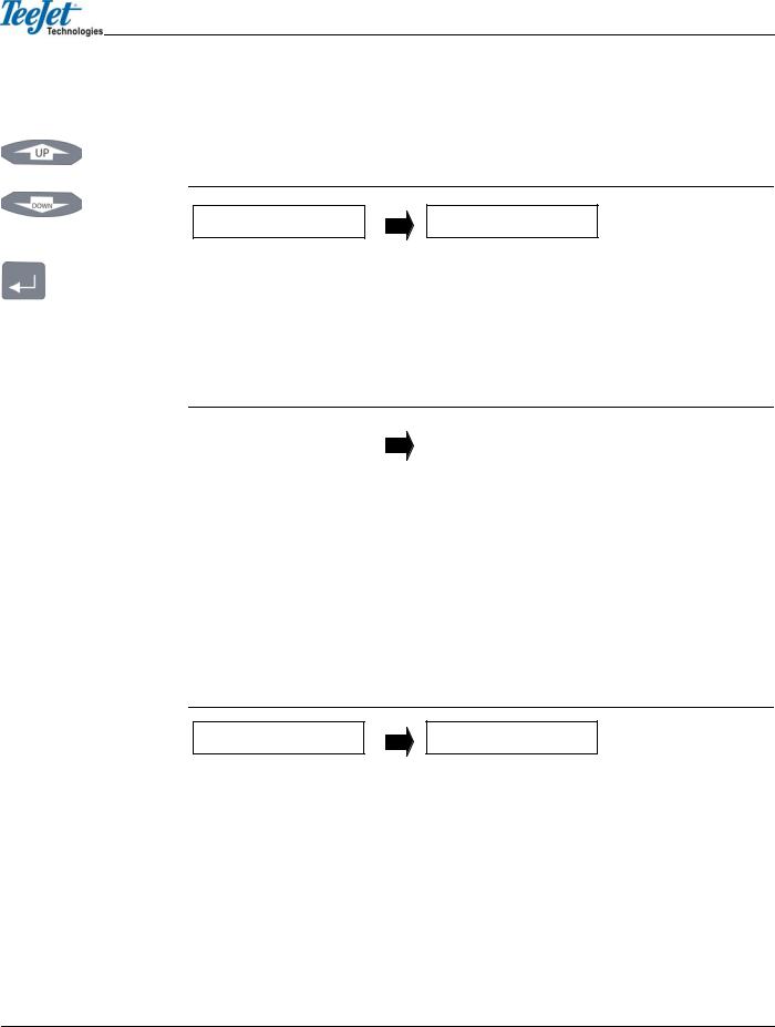
Figures with multiple menu items are depicted with menu items above and below, and with submenu items located to the right of the text item currently in view. Figure 1-2 represents several menu items.
Arrow buttons The current menu item in view is <SETUP> and is denoted with a black arrow to the right of the text. The figure shows that the Arrow buttons can be used to scroll between <START>, <SETUP>, and <TOOLS>. If the Enter button is pressed, the display will progress into <SETUP> and continue with <GUIDANCE> menu options. The Arrow buttons would then be able to scroll between <GUID-
ANCE>, <LIGHTBAR>, <SYSTEM>, etc.
Enter button
Figure 1-2: Example of Multiple Text Lines
Start
Setup Guidance
Tools Lightbar
System
There are two additional menu items that are located in almost every menu:
•<NEXT>
•<TO START>
Figure 1-3 illustrates the <NEXT> and <TO START> menu items in the System Setup menu list. Pressing the Enter button when <NEXT> is displayed will launch the next menu heading. For example, during Lightbar Setup, pressing Enter at <NEXT> will launch <SYSTEM>. Once in System Setup, pressing the Escape (ESC) button at <NEXT> will launch the <LIGHTBAR> menu again. Selecting <TO START> automatically reverts the operator back to the main menu. This is useful when it is necessary to make only minor modifications and quickly resume operation.
2 Chapter 1 - Introduction
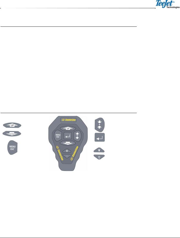
Figure 1-3: <Next> and <To Start> Examples
System |
|
|
Units |
|
|
||
|
|
|
|
|
|
|
Language |
|
|
|
|
|
|
|
|
|
|
|
Next |
|
|
|
|
|
|
|
|
|
|
|
To Start |
|
|
|
Wireless Remote Control
Operation of the CenterLine software occurs via remote keypad input and menu items displayed in the text display area. The Arrow buttons are used to scroll through menus and sub-menus. The Enter button is used to enter menus and sub-menus and accepts the appropriate entry. The Escape (ESC) button acts as a cancel button.
Figure 1-4: Wireless Remote Control
Up Arrow button |
Return to Point button |
|
|
Down Arrow button |
Enter button |
|
|
Menu/Escape button |
Brighter/Dimmer |
|
|
|
contrast buttons |
CenterLine 2.02 3
98-05054 R6
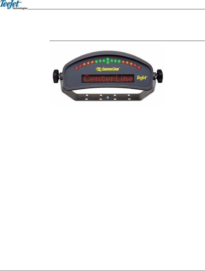
LIGHTBAR
Figure 1-5: CenterLine Lightbar
Lightbar Specifications |
|
Housing Material |
ABS/Poly carbonate alloy construction. |
Dimensions |
3.70” H x 9.40” W x 3.80” D / 95mm x 240mm x 100mm |
Weight |
0.8 lbs / 0.36 kg |
Processor |
Intel StrongARM |
Memory |
16 MB Ram, 2 MB Flash |
LEDs |
High-lumen red, yellow, and green radial light pattern and 10-char- |
|
acter LED alphanumeric text display. Full brightness control adjust- |
|
ment using wireless remote. |
Operating Voltage |
10-14 VDC |
Operating Temperature |
32o to 160oF / 0o to 70o C |
Storage Temperature |
-40o to 185o F / -40o to 85o C |
I/O to DGPS |
1 asynchronous RS232 |
I/O to Control Unit |
Wireless link operating at 433 MHz. FCC Part 15 and Industry Can- |
|
ada RS-210 certified. Other certifications pending. |
Mounting |
Mounting bracket supplied. Magnetic and suction mounts are |
|
optional. |
FCC STATEMENT
This device complies with Part 15 of the FCC Rules. Operation is subject to the following two conditions: (1) This device may not cause harmful interference; and (2) this device must accept any interference received, including interference that may cause undesired operation.
QS7CL7850094
QS7CL7850107
TR19JN96.008
Changes or modifications to the product, not expressly approved by TeeJet Technologies, Inc. could void the user’s authority as granted under Part 15 of the FCC Rules to operate the equipment.
4 Chapter 1 - Introduction

CHAPTER 2 - SETUP
It is assumed that the CenterLine system has been properly installed. Refer to the following CenterLine diagrams for system configuration.
QUICK START GUIDE
First Time Start-Up Sequence
1.Turn ON power to CenterLine.
2.The lightbar will perform a start-up sequence.
3.The lightbar will display the current software version.
4.The lightbar will display <START>.
5.Using the Arrow buttons, scroll until <SETUP> is displayed on the lightbar. Press the Enter button.
6.Configure the CenterLine system by choosing the appropriate settings under <GUIDANCE>, <LIGHTBAR>, and <SYSTEM>. It is important to enter the correct swath width for operation.
7.Use the Arrow buttons to locate <TO START>. Press the Enter button. The operator will return to the main menu.
8.Once <START> is displayed on the lightbar, press ENTER to begin operation.
Typical Start-Up Sequence
1.Turn ON power to CenterLine.
2.The lightbar will perform a start-up sequence.
3.The lightbar will display the current software version.
4.The lightbar will display <START>.
5.<START> will remain visible on the lightbar until the Enter button is pressed to begin operation or the Arrow buttons are pressed to select a menu option.
Arrow buttons
Enter button
CenterLine 2.02 5
98-05054 R6

Figure 2-1: CenterLine Without DGPS Receiver
A GPS data cable is required but not provided in the kit.
Adapter Cable  15’ / 5 m
45-05338
GPS Data Cable 15’ / 5 m 45-05337
to battery
Lightbar 78-50112
Wireless Remote 78-50107
CenterLine Power Cable 12’ / 4 m 45-05324
5 Amp
 Boom Sense +12V when booms are ON
 Ignition Sense +12V when ignition is ON
Power Cable
12’ / 4 m 45-05298
Figure 2-2: CenterLine With DGPS Receiver
RX400P 78-50062
Inline fuse
Lightbar 78-50112
|
|
|
Wireless Remote |
|
|
|
78-50107 |
RX370P |
|
|
|
78-50148 |
|
CenterLine Power Cable |
|
|
|
||
GPS Data Cable 15’ / 5 m |
12’ / 4 m 45-05324 |
||
|
|
||
45-05338 |
|
|
|
GPS Data Cable 15’ / 5 m |
|
5 Amp |
|
|
|
|
|
45-05337 |
|
|
|
|
Ignition Sense +12V |
|
|
|
when ignition is ON |
|
|
|
Power Cable |
|
Boom Sense |
|
12’ / 4 m 45-05298 |
+12V when |
|
|
to battery |
|
booms are ON |
6 Chapter 2 - Setup
CENTERLINE SETUP
CenterLine Setup allows for the configuration of the CenterLine product to best suit current guidance and mapping needs. For a complete overview of the setup process, refer to Figure 2-31 (page 22). CenterLine Setup consists of three sub-menus:
•Guidance
•Lightbar
•System
The top level of CenterLine software contains three menus available for selection: <START>, <SETUP>, and <TOOLS>. To access the setup menus, use the Arrow buttons to scroll to <SETUP> and press the Enter button. Once in <SETUP> mode, menu options will consist of <GUIDANCE>, <LIGHTBAR>, and <SYSTEM>. Access to setup options is achieved by pressing the Enter button.
Figure 2-3: CenterLine Setup Flow
Start
Setup |
Guidance |
Tools Lightbar
System
Guidance Mode
Guidance Mode allows for the establishment of several parameters that pertain to guidance functionality. To access Guidance Mode, use the Arrow buttons to scroll through the menu selections until <GUIDANCE> appears on the lightbar. Press the Enter button.
If the first menu item displayed is <SWATH MAN>, Swath Manager 5 has been detected on the system and needs to be configured. Refer to CHAPTER 2 - SWATH MANAGER for additional information.
Arrow buttons
Enter button
CenterLine 2.02 7
98-05054 R6

Arrow buttons
Enter button
Figure 2-4: Guidance Setup Flow
Guidance
Width
 Ahead
Ahead
 Antenna
 Status
Alarm
 GPS Type
1 Hz MSG
Next
 To Start
Table 2-1: Guidance Default Settings
Setting |
Default Value |
Change at Initial Startup |
|
|
|
|
|
|
Width |
30.0 feet/10 meters |
Required |
|
|
|
Ahead |
1.5 seconds |
Optional |
|
|
|
Antenna - Direction |
None |
Recommended |
|
|
|
Antenna - Distance |
0.0 feet |
Recommended |
|
|
|
Antenna - Height |
9.8 feet / 2.9 meters |
Recommended |
|
|
|
Status Detect |
Off |
Optional |
|
|
|
Alarm |
Off |
Recommended |
|
|
|
GPS Type |
DGPS |
Recommended |
|
|
|
1 Hz MSG |
Yes |
Not Recommended |
|
|
|
Swath Manager 5
The Guidance parameter <SWATH MAN> is only displayed when Swath Manager 5 is connected to the system. If Swath Manager 5 is not being used, this section is not required and can be skipped.
To adjust <SWATH MAN> settings in <GUIDANCE> mode, use the Arrow keys until <SWATH MAN> is displayed and press the Enter button. The Swath Manager menu contains four parameters:
•% overlap
•Sections
•Width 1-5
•Delay
8 Chapter 2 - Setup
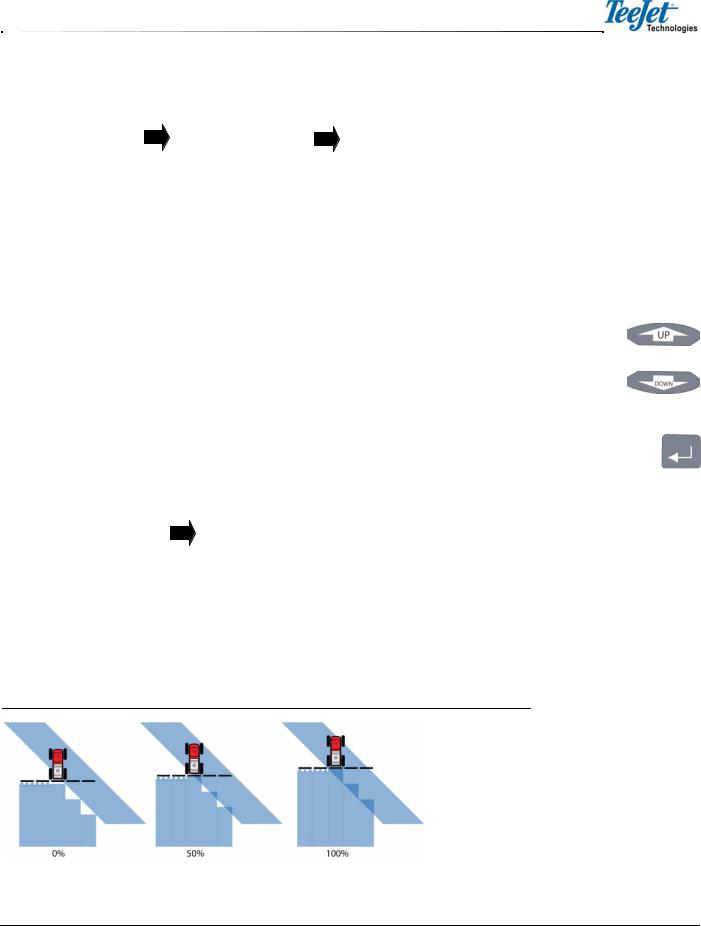
Figure 2-5: Swath Manager 5 Setup |
|
|
|
|
|
|
|
||||||
|
|
|
|
|
|
|
|
|
|
|
|
|
|
|
Setup |
|
|
|
Guidance |
|
|
Swath Man |
|
|
|||
Table 2-2: Swath Manager Settings |
|
|
|
|
|
|
|
||||||
|
|
|
|
|
|
|
|
|
|
|
|
|
|
|
|
|
|
|
|
|
|
|
|
|
|
|
|
|
Setting |
|
Description |
|
|
|
|
|
|
|
|||
|
|
|
|
|
|
|
|
|
|
|
|
|
|
|
|
|
|
|
|
|
|
|
|
|
|
|
|
|
% Overlap |
|
Boom sections are activated and deactivated based on the percentage of boom overlap |
|
|||||||||
|
|
|
setting (0%, 50%, and 100%) |
|
|
|
|
|
|||||
|
|
|
|
|
|
|
|
|
|
|
|
|
|
|
Sections |
|
The number of sections (1-5) active on the system. |
|
|||||||||
|
|
|
|
|
|
|
|
|
|
|
|
|
|
|
Width 1-5 |
|
The width for each boom 1-5. |
|
|
|
|
|
|||||
|
|
|
|
|
|
|
|
|
|
|
|
|
|
|
Delay |
|
The delay in seconds to turn the booms on and off when entering/exiting applied zones. |
|
|||||||||
|
|
|
|
|
|
|
|
|
|
|
|
|
|
% Overlap |
|
|
|
|
|
|
|
|
|
|
|
||
%Overlap determines the amount of overlap allowance to eliminate skips in application. Enter the |
Arrow buttons |
||||||||||||
appropriate pattern |
by using the Arrow buttons to select |
0%, 50%, or 100% and press the |
|
||||||||||
Enter button to accept the setting. |
|
|
|
|
|
|
|
||||||
Figure 2-6: % Overlap Settings |
|
|
|
|
|
|
Enter button |
||||||
|
|
|
|
|
|
|
|||||||
|
|
|
|
|
|
|
|
|
|
||||
|
% Overlap |
|
|
0% |
|
|
|
|
|
|
|||
|
|
|
|
|
|
|
|
|
|
|
|
|
|
|
|
|
|
|
|
|
50% |
|
|
|
|
|
|
|
|
|
|
|
|
|
|
|
|
|
|
|
|
|
|
|
|
|
|
|
100% |
|
|
|
|
|
|
Figure 2-7: % Overlap Illustration
CenterLine 2.02 9
98-05054 R6
Arrow buttons
Enter button
Sections
Enter the number of sections that are active in the system. Use the Arrow buttons to scroll to the appropriate number (1 - 5) and press the Enter button to accept the setting.
Figure 2-8: Number of Sections
Sections |
5 |
Width
Enter the width in feet / meters for boom section 1 by using the Arrow buttons to scroll through the options, followed by the Enter button. Repeat the process for the remaining boom sections. The total width of all boom sections is NOT the width that will be used for guidance. Refer to CHAPTER 2 - WIDTH for additional information.
Figure 2-9: Boom Section Width
Width 1 |
|
10 |
Delay
Enter the delay in seconds. This acts as the look ahead to turn booms on and off when entering and exiting applied zones.
Entering Applied Zones: When entering an applied zone, the setting acts as a look ahead and turns the booms off prior to entering the zone according to the number of seconds entered in Delay Setup. The setting allows time for the valves to shut off.
Exiting Applied Zones: When exiting an applied zone, the setting acts as a look ahead and turns the booms on prior to exiting the zone according to the number of seconds entered in Delay Setup. The setting allows time for the booms to re-engage before exiting the applied area.
Figure 2-10: Delay
Delay |
1.5 |
Width
The Guidance parameter Width measures the distance between guidelines. This width is typically the vehicle implement width, otherwise known as spread width. Setting this width slightly smaller than the actual width reduces skips. Setting this width slightly larger than the actual width reduces overlap. To adjust width setting, select <GUIDANCE> followed by the Enter button. Use the Arrow buttons and select <WIDTH>, followed by the Enter button. To increase the width, press the Up Arrow button. To decrease the width, press the Down Arrow button. Press the Enter button once the desired width is established. Width value is established in 0.1 foot increments.
10 Chapter 2 - Setup
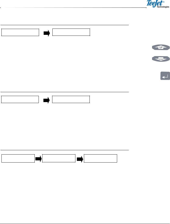
Figure 2-11: Guidance Width
Width |
58.5 |
Ahead
The Look Ahead value, Ahead, is the number of seconds ahead of the vehicle the operator desires the software to calculate the cross track error. Based on the vehicle’s speed and trajectory combined with the look ahead value, CenterLine can determine where the vehicle will be with respect to the current guideline. This setting will vary based on the operator’s driving ability and preference. This value is only used during Parallel Guidance. It is not used during Headland Guidance or Circle Pivot. A look ahead value that best fits the operator will result in smoother guidance operation. Typically, this value is set to 1.5 or 2.0 seconds. To adjust Ahead settings, select <GUIDANCE> followed by the Enter button. Use the Arrow buttons until <AHEAD> is displayed in the text window. Press the Enter button and use the Arrow buttons to adjust the value. Press the Enter button to save the settings and return to the Guidance setup menu.
Figure 2-12: Ahead Value
Ahead |
1.5 |
Antenna
The Antenna sub-menu defines the spatial relationship between the GPS antenna and the vehicle implement or delivery point. The GPS antenna should always be mounted along the vehicle’s center line (refer to Figure 2-16). The two primary antenna settings are <DIRECTION> and <DISTANCE>.
To enter the Antenna sub-menu, navigate to <GUIDANCE>, use the Arrow buttons until <ANTENNA> is displayed, and press the Enter button. Several options will be displayed: <DIRECTION>, <TO START>, <NEXT>, <HEIGHT>, and <DISTANCE>. Press the Enter button to save the settings and return to the Guidance setup menu.
Figure 2-13: Antenna Sub-Menu
Guidance Antenna Direction
Antenna - Direction
The Direction sub-menu defines the direction from the swath (refer to Figure 2-16). To change the Direction setting, navigate to <GUIDANCE>, use the Arrow buttons until <ANTENNA> is displayed, and press the Enter button. Use the Arrow buttons to select <DIRECTION> and press the Enter button. Scroll through the direction list using the Arrow buttons until the desired direction is displayed in the text window. Press the Enter button to save the setting and return to the Guidance setup menu.
Arrow buttons
Enter button
CenterLine 2.02 11
98-05054 R6
 Loading...