


854 Sprayer Control

854SprayerControl
COPYRIGHTS
© 2010 TeeJet Technologies. All rights reserved. No part of this document or the computer programs described in it may be reproduced, copied, photocopied, translated, or reduced in any form or by any means, electronic or machine readable,
recording or otherwise, without prior written consent from TeeJet Technologies.
TRADEMARKS
Unless otherwise noted, all other brand or product names are trademarks or registered trademarks of their respective companies or organizations.
LIMITATION OF LIABILITY
TEEJET TECHNOLOGIES PROVIDES THIS MATERIAL “AS IS” WITHOUT WARRANTY OF ANY KIND, EITHER EXPRESSED OR IMPLIED. NO COPYRIGHT LIABILITY OR PATENT IS ASSUMED. IN NO EVENT SHALL TEEJET TECHNOLOGIES BE LIABLE FOR ANY LOSS OF BUSINESS, LOSS OF PROFIT, LOSS OF USE OR DATA, INTERRUPTION OF BUSINESS, OR FOR INDIRECT, SPECIAL, INCIDENTAL, OR CONSEQUENTIAL DAMAGES OF ANY KIND, EVEN IF TEEJET TECHNOLOGIES HAS BEEN ADVISED OF SUCH DAMAGES ARISING FROM TEEJET TECHNOLOGIES SOFTWARE
TableofContents |
|
COPYRIGHTS.......................................................................................................................................................... |
I |
TRADEMARKS........................................................................................................................................................ |
I |
LIMITATION OF LIABILITY.................................................................................................................................. |
I |
CHAPTER 1 - INTRODUCTION..................................................................... |
1 |
Power On the Console_ _______________________________________________ 2 |
|
Power Off the Console_ _______________________________________________ 2 |
|
CHAPTER 2 - OEM PROGRAM MODE......................................................... |
3 |
Number of Boom Section Switches On the Console_________________________ 3 |
|
Lane Width (GLM Working Units)________________________________________ 3 |
|
Regulation Parameters________________________________________________ 4 |
|
Minimum Regulating Valve Voltage________________________________________ 4 |
|
Regulation Stop Band_________________________________________________ 4 |
|
Rotation Time of Regulating Valve_______________________________________ 5 |
|
Display Stabilization__________________________________________________ 6 |
|
Data Display Screen Options_ __________________________________________ 6 |
|
Calibrate Tip Level Percent_____________________________________________ 6 |
|
Digital Output #2____________________________________________________ 7 |
|
Dual Boom Regulation Mode___________________________________________ 8 |
|
Fill Valve Default_ ____________________________________________________ 8 |
|
Auto Power Down____________________________________________________ 9 |
|
www.teejet.com i

854SprayerControl |
|
TEEJET COMMUNICATION SYSTEM (TCS) CONFIGURATION............................................................. |
9 |
Job Operating System________________________________________________ 9 |
|
Console Identification Number_ _______________________________________ 10 |
|
Maximum Speed Achieved___________________________________________ 10 |
|
Hidden Area Counter_ _______________________________________________ 10 |
|
Hidden Volume Counter______________________________________________ 10 |
|
PRESSURE TRANSDUCER CALIBRATION (P HI)..................................................................................... |
11 |
Memory Save Function_______________________________________________ 12 |
|
CHAPTER 3 - SYSTEM SETUP MODE....................................................... |
13 |
Selection of Working Units____________________________________________ 13 |
|
Reset to Defaults____________________________________________________ 13 |
|
Speed Sensor Calibration_____________________________________________ 14 |
|
Proximity/Magnetic Pulses______________________________________________ 14 |
|
Automatic Calibration__________________________________________________ 14 |
|
Distance Counter___________________________________________________ 15 |
|
Pressure Hold______________________________________________________ 15 |
|
Pressure Sensor Installed_ ____________________________________________ 16 |
|
Pressure Transducer Low Pressure Calibration (P Ref)______________________ 16 |
|
Automatic Calibration__________________________________________________ 16 |
|
Pressure Transducer Maximum Rating (P HI)______________________________ 17 |
|
Flow Meter Installed_________________________________________________ 17 |
|
Flow Meter Pulses___________________________________________________ 18 |
|
Manual Entry_________________________________________________________ 18 |
|
Automatic Calibration__________________________________________________ 18 |
|
Flow Sensor Minimum Flow Capacity_ __________________________________ 19 |
|
Sensor Selection____________________________________________________ 20 |
|
Section Valve Type__________________________________________________ 20 |
|
Pressure Regulating Mode____________________________________________ 21 |
|
Regulating Valve Capacity_ ___________________________________________ 22 |
|
Regulating Valve Speed - Coarse Adjustment_____________________________ 22 |
|
Regulating Valve Speed - Fine Adjustment_______________________________ 23 |
|
Tank Volume_ ______________________________________________________ 23 |
|
Low Tank Volume Alarm______________________________________________ 24 |
|
Fill Flow Meter Calibration_ ___________________________________________ 24 |
|
Manual Entry_________________________________________________________ 24 |
|
Automatic Calibration__________________________________________________ 24 |
|
Communications____________________________________________________ 26 |
|
Printing Memory Contents______________________________________________ 26 |
|
Using GPS___________________________________________________________ 27 |
|
ii www.teejet.com

854SprayerControl
Communicating With a Laptop Running Fieldware Software__________________ 27 Logging Information to a Laptop running Logging Software__________________ 28
GPS Speed_________________________________________________________ 28 Use External Rate_ __________________________________________________ 28
Simulated Ground Speed_____________________________________________ 29
Low Speed___________________________________________________________ 29 High Speed___________________________________________________________ 29
Auto Master Off - Speed______________________________________________ 30 Minimum Pressure Setting____________________________________________ 30 Maximum Pressure Setting___________________________________________ 30 Audible Alarm______________________________________________________ 31 Dual Boom On Setting_ ______________________________________________ 31 Memory Reload Function_____________________________________________ 32
CHAPTER 4 - APPLICATION PRESET SETUP MODE................................ |
33 |
Tip Spacing_ _______________________________________________________ 33 Number of Tips Per Boom Section______________________________________ 34
Density___________________________________________________________ 34
Alternate Density Used_________________________________________________ 34 Density Value_________________________________________________________ 34
Tip Selection_______________________________________________________ 35 Target Application Rate_ _____________________________________________ 35
Calculation Steps___________________________________________________ 36
Known Pressure Calculation____________________________________________ 36 Known Speed Calculation______________________________________________ 36
CHAPTER 5 |
- OPERATIONS....................................................................... |
37 |
Sprayer Evaluation_ _________________________________________________ 37 |
|
|
Spraying__________________________________________________________ 38 |
|
|
CHAPTER 6 |
- FEATURES............................................................................ |
39 |
Area/Volume Display________________________________________________ 39
Memory Feature_ ___________________________________________________ 40
Viewing Memory Information____________________________________________ 40 Clearing Memory Locations_____________________________________________ 40 Saving Information to Memory___________________________________________ 40
Tank Feature_ ______________________________________________________ 41
Auto Tank Filling______________________________________________________ 41 Tank Volume Feature___________________________________________________ 42
Viewing Remaining Tank Volume______________________________________ 42 Resetting Tank Volume______________________________________________ 42
www.teejet.com iii

854SprayerControl
Application Alarm___________________________________________________ 42
Sensor LED Alarms_ _________________________________________________ 43
No Speed Alarm_______________________________________________________ 43 No Flow Alarm________________________________________________________ 43 No Pressure Alarm____________________________________________________ 44 Flow/Pressure Discrepancy Alarm_______________________________________ 44
Boost Mode________________________________________________________ 44
Boost Up____________________________________________________________ 44 Boost Down__________________________________________________________ 45
Auto Power Down___________________________________________________ 45 Smart Sensing______________________________________________________ 45
iv www.teejet.com
854SprayerControl
CHAPTER 1 - INTRODUCTION
This User Guide provides information for software version 1.20.
Make sure that all hardware components are properly installed and tested. Before starting the programming process, confirm that the console and all sensors are working properly.
IMPORTANT! Before beginning, review the following Program Guidelines that control the programming process.
To exit any Setup Mode, press and hold the PROGRAM key for 3 seconds. The inputs are stored and the computer will exit Program Mode.
To increase the value of a programmable digit, press the PLUS key. To decrease the value, press the MINUS
 key. These keys are located directly to the right of the display. For some program steps, press and hold the PLUS
 and MINUS
 keys to quickly change the values. Press the PLUS
 and MINUS
 keys once to increment/decrement the values by one unit.
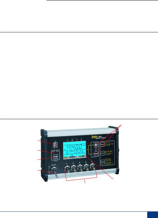
Figure 2-1: 854 Console
Press and hold the AUTO/MAN key to reset the value to “0” or restore factory default settings during some steps.
Press the PROGRAM key to advance the system to the next program step. After the final program step is complete, the console will finish the programming loop and return to the initial programming step.
System Setup mode contains the options that customize the controller to the sprayer or sprayer components. These include calibration steps and parameters that seldom change once programmed.
Application Setup mode contains settings that are frequently changed (tip spacing, number of tips per boom section, density, nozzles used, and target application rate).
Sensor LED Alarms |
|
Plus and Minus keys |
|||
On/Program button |
|
|
|
|
Preset key |
|
|
|
|
||
|
|
|
|
||
Auto/Manual mode indicator |
|
||||
|
|||||
|
Tank key |
||||
Auto/Man key |
|
||||
|
|||||
|
Memory key |
||||
Master Switch |
|
||||
|
|
||||
|
|
|
|
Display |
|
|
Boom Section Controls |
|
|
||
www.teejet.com 1
854SprayerControl
Power On the Console
The 854 console can be powered on by pressing the PROGRAM key one time. The console will initially display the software version at the top of the screen and the serial number of the console at the bottom of the screen. After approximately 5 seconds, the console will enter into swath width view.
Press the PROGRAM key to advance to normal Operations mode.
Figure 2-2: Power On the Console
SFt 1.20
H28 0008
Power Off the Console
To power off the 854 console, press and release the MINUS and PROGRAM
 keys simultaneously. The console will save new information (area and volume counters) to memory before it powers down. The console also has an automatic power down feature. This is described in further detail in the Features section of this User Guide.
Figure 2-3: Power Off the Console
2 www.teejet.com

854SprayerControl
CHAPTER 2 - OEM PROGRAM MODE
The OEM Program Mode contains configuration steps for the console. The console is typically pre-configured before being shipped. Changing the configurations is not recommended unless instructed to do so as it may adversely affect the performance of the controller.
•To enter the OEM Program Mode:
•Begin with the console powered “Off”.
•Press the MINUS key and the PROGRAM
 key simultaneously to turn the console “Off” if required.
• Press and hold the PLUS and MINUS
 keys. While still holding them, press the PROGRAM
 key 4 times.
• Release all keys.
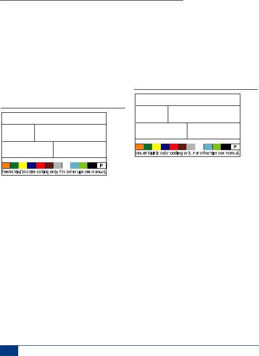
Figure 3-1: Entering OEM Program Mode
nr 5
SEC
Number of Boom Section Switches On the Console
The number of individual boom section switches actually present on the control console (regardless of the number of boom sections that are on the sprayer) can be programmed.
•Press and hold the AUTO/MAN key for 3 seconds to set the value to “1”.
•Press the AUTO/MAN key once to reset the value to the default value of “5”.
•Press the PROGRAM key to accept the value and advance to the next program step.
Lane Width (GLM Working Units)
When Gallons per Lane Mile “GLM” is selected as the working units, this screen will allow the operator to enter the lane width in inches.
•Use the PLUS or MINUS
 keys to modify the value.
•Press the Program key to accept the value and advance to the next program step.
Figure 3-2:
Lane Width (GLM Working Units) Window
144
•Use the PLUS or MINUS
 keys to modify the value.
•1 to 11 switches can be programmed.
•This number will determine the number of spray tips per boom section during the System Setup Mode.
www.teejet.com 3
854SprayerControl
Regulation Parameters
The regulation algorithm is configured with the next three parameters:
1.Minimum Regulating Valve Voltage: the minimum voltage that can drive the regulating valve.
2.Regulation Stop Band: the maximum allowed application error rate.
3.Rotation Time of Regulating Valve: the total time required to close the regulating valve at maximum speed.
These three OEM parameters depend on the regulating valve used.
Minimum Regulating Valve Voltage
The console uses variable voltages to drive the regulating valve. Select the minimum voltage that the regulating valve needs to make it turn at its slowest rotation speed (i.e., if the motor of the regulating valve turns with a minimum of 3.5v, the number should be used in this location).
The affect of this parameter on the regulation behavior is illustrated in Figure 2-4. This value must match the actual operation of the regulating valve used. Check with the valve manufacturer for the value.
•Use the Plus or MINUS
 keys to change the voltage.
•Press and hold the AUTO/MAN key for 3 seconds to set the value to “0.0”.
•Press the AUTO/MAN key once to set to the default value of 3.5v.
•Press the PROGRAM key to accept the value and advance to the next program step.
NOTE: Standard TeeJet Technologies regulating valve minimum voltage is 3.5v.
If 12v is selected as a minimum voltage, no variable voltage regulation occurs. Instead, a pulse regulation occurs. This is necessary when using solenoid operated regulating valves (i.e., a Ramsay valve).
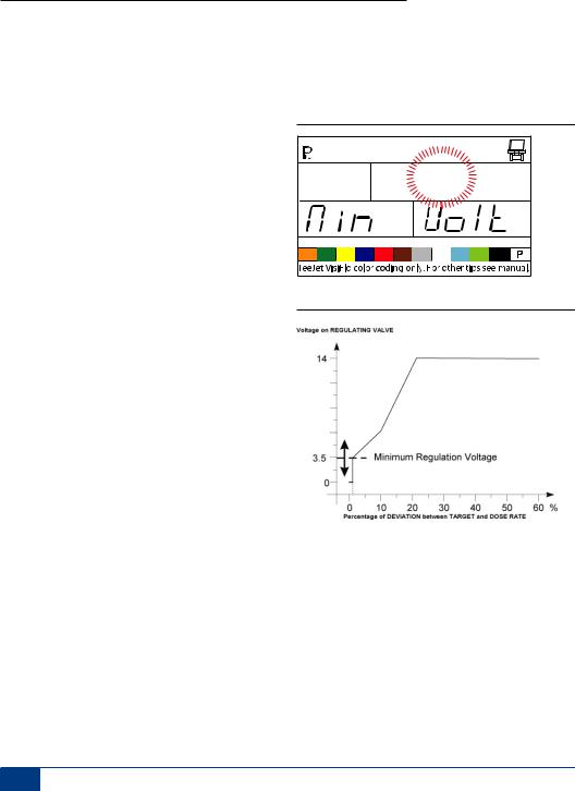
Figure 3-3: Minimum Regulating Valve Voltage
rE6 3.5
Figure 3-4: Voltage Comparison
Regulation Stop Band
The Regulation Stop Band is the maximum error percentage allowed on the application rate before the regulating valve reacts (i.e., if a stop band of 1.5% is selected, there is no action on the regulating valve if the actual application rate is within 1.5% of the target rate). This minimum percentage prevents the regulating valve from oscillating in a narrow band around the target point.
•Use the PLUS or MINUS
 keys to change the regulation stop band (value is expressed
4 www.teejet.com

854SprayerControl
in error percentage). The maximum value is 10.0%.
•Press and hold the AUTO/MAN key for 3 seconds to set the value to “0.0”.
•Press the AUTO/MAN key once to set the value to the default setting of “1.5%”.
•Press the PROGRAM key to accept the value and advance to the next program step.
Figure 3-5: Regulation Stop Band
rE6 1.5
STP BAnd
Rotation Time of Regulating Valve
The Rotation Time of Regulating Valve is the number of seconds the regulating valve needs to turn from the complete closed position to the complete open position at the nominal voltage (i.e., 14v).
Use the PLUS or MINUS
 keys to change the rotating time of the regulating valve in seconds (minimum “0’s”, maximum “50’s”).
Press and hold the AUTO/MAN key for 3 seconds to set the value to “0.0”.
Press the AUTO/MAN key once to set the value to the default setting of “6 seconds”.
Press the PROGRAM key to accept the value and advance to the next program step.
NOTE: Standard TeeJet regulating valve rotation time is 6 seconds.
Figure 3-6: Effects of Parameters |
|
|
The console uses this parameter to control the |
||||
|
|
regulation speed. The value must match the actual |
|||||
|
|
|
|
|
|
||
Voltage on REGULATING VALVE |
|
|
|
|
operation of the regulating valve used. Check with |
||
14 |
|
|
|
|
|
the valve manufacturer for this value. |
|
|
|
|
|
|
Figure 3-7: Rotation Time of Regulating Valve |
||
|
|
|
|
|
|
||
|
|
|
|
|
|
rE6 |
6 |
0 |
Regulation Stop Band |
|
SPd |
SEC |
|||
|
|
|
|
|
|
|
|
0 |
10 |
20 |
30 |
40 |
50 |
60 % |
|
Percentage of DEVIATION between TARGET and DOSE RATE |
|
|
|||||
www.teejet.com 5
854SprayerControl
Display Stabilization
Display Stabilization establishes the stabilization rate that steadies the Application Rate displayed during minor adjustments of the control system. The controller will continue to make the required adjustments at all times. Enter the percentage of allowable change from the target rate in this step.
For example, the system has a target rate of 20 GPA with 5% programmed for Display Stabilization. The display will indicate 20 GPA at any time the actual rate is +/- 5%, or:
•Use the PLUS or MINUS
 keys to change the value.
•Press and hold the AUTO/MAN key for 3 seconds to set the value to “0.0”.
•Press the AUTO/MAN key once to set the value to the default setting of “5%”.
•Press the PROGRAM key to accept the value and advance to the next program step.
NOTE: The Display Stabilization value is limited to 20%. A value of 0% will disable the setting.
Figure 3-8: Display Stabilization
s O |
5 |
diS |
rAtE |
Data Display Screen Options
The lower right hand display used during normal operations mode can be customized to display:
•volume sprayed
•area covered
•both volume sprayed and area covered (alternating every 3 seconds)
To customize the data display options:
•Use the PLUS or MINUS
 keys to change the data to be displayed.
•Press the PROGRAM key to accept the value and advance to the next program step.
Figure 3-9: Data Display Screen
dAt bOth
Calibrate Tip Level Percent
If both a pressure sensor and a flow meter are installed and being used, the 854 uses one sensor to cross check the other for system errors.
Select the primary sensor (used for regulation) in the Sensor Select step of System Setup Mode. The opposite sensor will automatically perform the crosschecking function.
The Calibrate Tip Level % will establish the % of allowable error between the sensors before an alarm is activated. All sprayer systems have some discrepancy between pressure and flow due to pressure drops and positioning of sensors.
•Use the PLUS or MINUS
 keys to change the % of allowable error.
•Press the PROGRAM key to accept the value and advance to the next program step.
NOTE: It is recommended that this value remain at 50% unless instructed otherwise.
6 www.teejet.com
|
|
854SprayerControl |
|
Figure 3-10: Calibrate Tip Level % |
Figure 3-11: Digital Output # 2a |
||
CAL |
50 |
Out |
2 |
tIP |
LEv |
nOT |
USEd |
Digital Output #2
The primary output from the console computer drives the pressure regulating valve. A second output is available and can be configured for the following uses:
•Not Used - the second digital output is not used
•Dual Boom - used to control a shutoff valve on a second boom line that is automatically activated based on speed and pressure
•Fill Valve - used to automatically shut off a valve or switch during a tank filling operation when used with a tank fill flow meter
To establish the Digital Output settings:
•Use the PLUS or MINUS
 keys to change the value.
•Press the PROGRAM key to accept the value and advance to the next program step.
Out |
2 |
dUA |
bOOn |
Out |
2 |
FiL |
vALV |
www.teejet.com 7
854SprayerControl
Dual Boom Regulation Mode
NOTE: This step will only be displayed if “Dual Boom” was selected during the DIGITAL OUTPUT #2 step.
Dual Boom Regulation Mode is used to regulate the dual boom feature by either speed (SPD) or pressure (PRS).
If speed is used to regulate the mode, when the vehicle reaches the designated speed, the second boom line will turn On/Off.
If pressure is used to regulate the mode, when the pressure reaches the designated amount, the second boom line will turn On/Off.
•Use the PLUS or MINUS
 keys to change the value.
•Press the PROGRAM key to accept the value and advance to the next program step.
The value selected will determine how programming steps appear during System Setup Mode. Specific speed or pressure values to be used during operation are selected during the System Setup Mode.
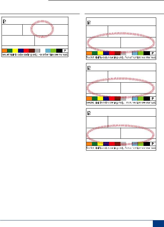
Figure 3-12: Dual Boom Regulation Mode - Speed
db SPd
re6
Figure 3-13: Dual Boom Regulation Mode - Pressure
db PrS
re6
Fill Valve Default
NOTE: This step will only be displayed if “Dual Boom” was selected during the DIGITAL OUTPUT #2 step.
The Fill Valve Default establishes the normal operating state of the fill valve being used. If the fill valve requires a +12v signal during the spraying operation, the valve default is “On”. If the fill valve requires a +12v signal during the filling operation, the valve default is “Off”.
•Use the PLUS or MINUS
 keys to change the value.
•Press the PROGRAM key to accept the value and advance to the next program step.
Figure 3-14: Fill Valve Default
FiL OUt
OFF dFLt
8 www.teejet.com
854SprayerControl
Auto Power Down
The 854 console is designed to automatically power down after 10 minutes of inactivity from the sensor or operator. To adjust the length of time:
•Use the PLUS or MINUS
 keys to change the value of the power down time.
•Press the PROGRAM key to accept the value and advance to the next program step.
NOTE: If the Power Down Time is set to “0”, the Auto Power Down feature will be disabled.
Figure 3-15: Auto Power Down
Pur 10
Off
TEEJET COMMUNICATION SYSTEM (TCS) CONFIGURATION
NOTE: If the TeeJet Communication System (TCS) package was not purchased for this console, the next 2 programming steps DO NOT pertain to your spraying operation. IF THIS IS THE CASE, THESE VALUES SHOULD BE LEFTAT THE DEFAULT SETTINGS.
Job Operating System
•Job No (Default) - the console uses application parameters entered by the operator only
•Job Only - the console uses application parameters entered from the TeeJet Communication System only
•Job Both - the console accepts application parameters for both the operator and the TeeJet Communication System
To establish the Job Operating System settings:
•Use the PLUS or MINUS
 keys to change the value.
•Press the PROGRAM key to accept the value and advance to the next program step.
Figure 3-16: Job Operating System
JOb
www.teejet.com 9

854SprayerControl
Console Identification Number
The TeeJet Communications System (TCS) is capable of monitoring and communicating with several consoles at one time. Therefore each console communicating with a single TCS must be assigned a unique identification number. THE DEFAULT NUMBER IS “1”.
•Use the PLUS or MINUS
 keys to change the value.
•Press the PROGRAM key to accept the value and advance to the next step.
Figure 3-17: Console Identification Number
1
Id
Maximum Speed Achieved
The Maximum Speed Achieved feature records the maximum speed achieved by the sprayer. This value can only be cleared by an authorized TeeJet Dealer, Distributor, or Representative.
•Press the PROGRAM key to advance to the next step.
Figure 3-18: Maximum Speed Achieved
SPd
MPH
5.3 High
Hidden Area Counter
The Hidden Area Counter can only be viewed and cleared during this step. This value can only be cleared by an authorized TeeJet Dealer, Distributor, or Representative.
•Press the PROGRAM key to advance to the next step.
Figure 3-19: Hidden Area Counter
Ar
1480Ac
Hidden Volume Counter
The Hidden Volume Counter can only be viewed and cleared during this step. This value can only be cleared by an authorized TeeJet Dealer, Distributor, or Representative.
•Press the PROGRAM key to advance to the next step.
Figure 3-20: Hidden Volume Counter
uOL
4630Vol
10 www.teejet.com

854SprayerControl
PRESSURE TRANSDUCER CALIBRATION (P HI)
NOTE: This step may not appear if the console has not been programmed during System Setup Mode for use with a pressure sensor.
WARNING! It is not recommended that this calibration procedure be initially performed. It should ONLY be performed if a known pressure drop exists between the Pressure Transducer and the spray tips and if a TeeJet representative recommends performing it.
The pressure sensor can be automatically calibrated to compensate for pressure loss between the pressure transducer and the spray tips.
•Press and hold the PLUS and MINUS
 keys to start the Auto Calibration process. The lower left hand screen will go blank.
•Place an accurate manual pressure gauge in the spray line, as close to the spray tips as possible.
•Activate the pump and boom sections to be used for calibration.
•Turn the Master Switch to the “On” position.
•Press the PLUS or MINUS
 keys to adjust the pressure on the manual pressure gauge near the tips to the desired pressure to be used for the calibration. The higher the pressure the better.
•Turn the Master Switch to the “Off” position.
•Use the PLUS or MINUS
 keys to adjust the displayed pressure to match the actual calibration pressure.
•Activate the pump and boom sections to be used for calibration.
•Confirm that the actual pressure matches the displayed pressure.
•Press the PROGRAM key to begin calibration.
•The console will display “0-10” during the calibration process.
•The new Pressure Transducer Maximum Rating will be displayed. The value is automatically carried over to the System Setup Mode.
•Press the PROGRAM key to advance to the next step.
Figure 3-21: Pressure Transducer Calibration
145PSI PHi
PrS SenS
PSI75 16.2
206
www.teejet.com 11
 Loading...