

Page 1

OPERATING INSTRUCTIONS
LH 3000
LH No. 023-160-UK Version 2.00
LH Technologies Denmark ApS
Mølhavevej 2
9440 Aabybro
Denmark
Tel. +45 9696 2500
Fax. +45 9696 2501
Internet: http://www.lh-agro.com/
Page 2

LH 3000
OPERATING MANUAL
2 LH A
GRO
Page 3

LH 3000
OPERATING MANUAL
Contents
INTRODUCTION .................................................................................................................5
DESCRIPTION OF THE SYSTEM ......................................................................................6
LH 3000 MONITOR .............................................................................................................7
ENCODING KEYS...............................................................................................................7
OPERATION IN GENERAL.................................................................................................8
ENCODING .........................................................................................................................8
01 WORKING WIDTH................................................................................................. 9
02 WHEEL CIRCUMFERENCE ..................................................................................9
03 FLOW FIGURE ....................................................................................................10
04 BOOM SECTION .................................................................................................11
05 CHOOSE OF SPEED SENSOR ..........................................................................12
06 ALARM LIMITS FOR APPLICATION RATES ......................................................12
07 ALARM LIMITS FOR PRESSURE .......................................................................12
08 ALARM LIMITS FOR RPM...................................................................................13
09 PLUS/MINUS CHANGES IN APPLICATION RATE.............................................13
10 DRIVING FACTOR (REGULATION SPEED).......................................................13
11 UNIFORM PRESSURE COMPENSATION..........................................................13
12 METRIC/IMPERIAL..............................................................................................14
13 CHOOSE OF IMPLEMENT SENSOR.................................................................. 14
14 PRINTER TYPE ...................................................................................................14
FUNCTION KEYS.............................................................................................................. 15
RPM ..........................................................................................................................15
TIMER .......................................................................................................................15
ZEROING OF TIMER............................................................................................15
SPEED ...................................................................................................................... 15
METRES ...................................................................................................................16
REMAINING AREA ...................................................................................................16
AREA RECORDING.................................................................................................. 16
AREA PER HOUR.....................................................................................................17
LITRES PER MINUTE...............................................................................................17
REMAINING LITRES IN THE TANK .........................................................................17
CONSUMPTION FROM TANK .................................................................................18
WORKING PRESSURE ............................................................................................ 18
APPLICATION ..........................................................................................................19
PLUS/MINUS APPLICATION CHANGES ................................................................. 19
JOBNO......................................................................................................................20
MEMO .......................................................................................................................20
CLEAR ......................................................................................................................21
PRINT .......................................................................................................................21
SYSTEM ...................................................................................................................21
AGRO 3
LH
Page 4

LH 3000
OPERATING MANUAL
TEST OF SENSORS ......................................................................................................... 22
SPEED SENSOR.................................................................................................. 22
FLOW METER ......................................................................................................22
PRM SENSOR......................................................................................................22
PRESSURE SENSOR ..........................................................................................23
MOTOR CONTROL ..............................................................................................23
IMPLEMENT SENSOR.........................................................................................23
ERRORS AND WARNINGS ..............................................................................................23
4 LH A
GRO
Page 5

INTRODUCTION
Congratulation on your new LH 3000 monitor. This monitor is an advanced
auxililary machine, which can be a great assistent for you for many years,
presupposed correctly, encoded, used as maintained.
In the development of the LH 3000 great importance was attached to the
simplifying of the daily use. This has been made by “removing” all encoding keys
and arranging all encoding values in a register under only one key, the “SYSTEM”
key. This makes the daily use much simpler.
Thus it is of great importance that the encoded values are frequently checked and
especially before use of automatic applications as the encoded values are not
visible immediately. In this connection it is recommended to keep the form for
encoded data up to date.
LH 3000
OPERATING MANUAL
Also it is recommended to “test” the system frequently by the integrated test
programme, especially before use of automatic application.
The entire responsibility rests with the user to ensure that the programming of the
monitor is accurately carried out. LH Agro can under no circumstances be hold
responsible for erroes in programming or their consequences.
On the following pages the individual functions will be explained. It is
recommended to operate the monitor while reading the manual.
AGRO 5
LH
Page 6
LH 3000
OPERATING MANUAL
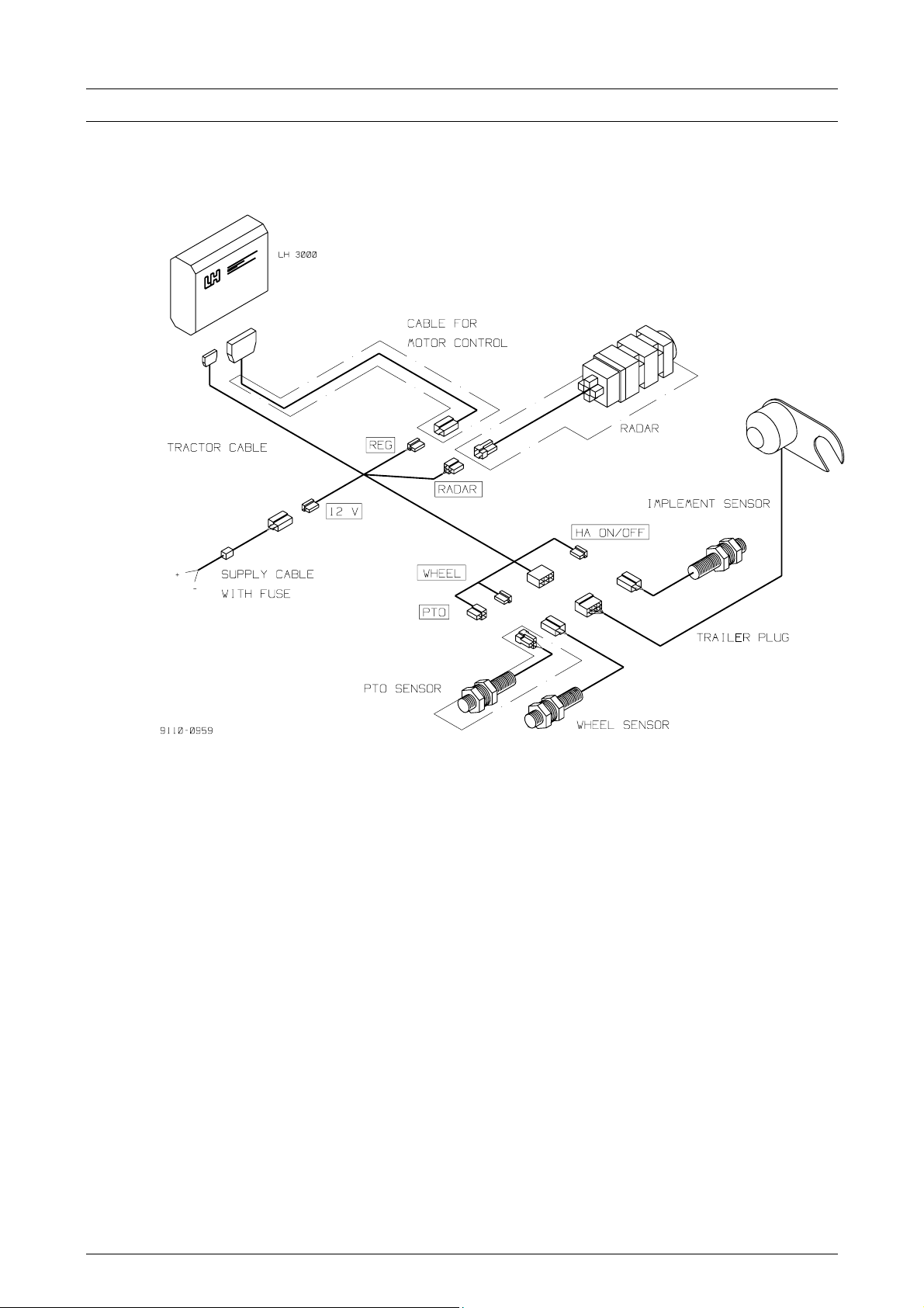
DESCRIPTION OF THE SYSTEM
On the below drawing the LH 3000 system is illustrated. The standard kit has
been made with full-drawn lines and extra equipment with broken lines.
6 LH A
GRO
Page 7
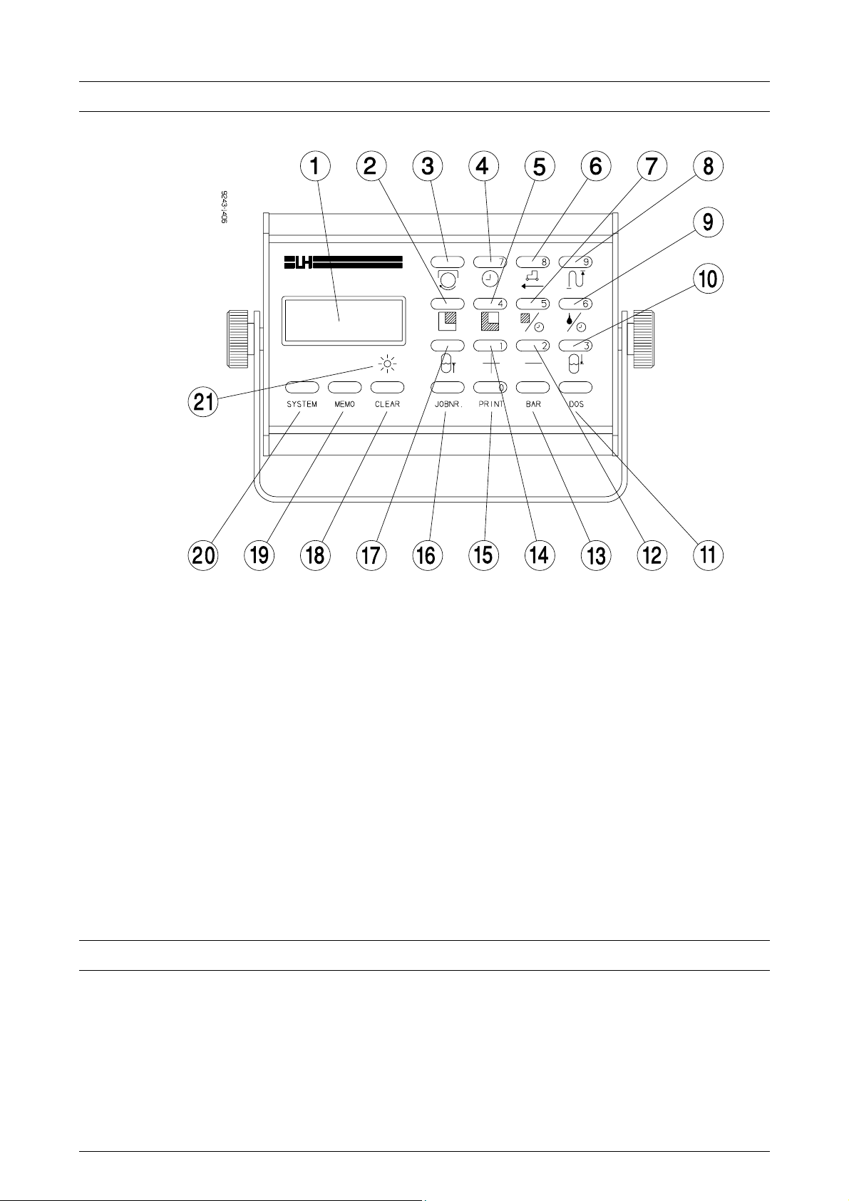
LH 3000 MONITOR
LH 3000
OPERATING MANUAL
1. Display
2. Remaining area to work
3. PTO shaft revolutions per minute
4. Working time (Timer)
5. Area counter (trip and total)
6. Speed km/h
7. Hectar per hour
8. Travelled distance in metres
9. Application rate per minute
10. Litre consumption from tank
11. Litre application per hectar
ENCODING KEYS
12. Step application (reduction)
13. Manometer pressure in bar
14. Step application (increase)
15. Print of stored data in the memory
16. Field No. or Customer No. Max 9
digits.
17. Remaining litres in tank
18. Clear key
19. Memory of data
20. Encoding values 1-14
21. Control lamp for implement sensor
The figure keys 0 – 9 are only lit and thus visible when they are to be used, e. g.
when values are to be encoded.
AGRO 7
LH
Page 8

LH 3000
OPERATING MANUAL
OPERATION IN GENERAL
All encoding values (basic data) for the calculations are divided in 14 values (1 –
14).
Th encoding values will appear by pressing the “SYSTEM”-key after which the
numerical keyboard will be lit and the values can be encoded.
By repeated press on the “SYSTEM”-key the order of encoding values (1 – 14)
can be leafed through.
A “bip” will sound when a key is pressed during normal operation (not during
encode) and the chosen function will be lit.
If one of the encoded alarm limits is exceeded 3 quick “bip2 will be given
(repeated at intervals) and a displayed error code states alarm type.
ENCODING
All encode value are arranged under the “SYSTEM”-key:
The order of encoding values is:
01 = Working width in cm.
02 = Wheel circumference in cm.
03 = Flow figure.
04 = Boom sections.
05 = Choice of speed sensor.
06 = Warning limit application rate.
07 = Warning limit pressure.
08 = Warning limit rpm
09 = +/- change of application rate
10 = Time factor (automatic dosage).
11 = Uniform pressure
12 = Metric/Imperial
13 = Choice of implement sensor
14 = Printer
By means of the “SYSTEM”-key it can be leafed through the order of the above
values, step by step.
The encoding is ended by pressing the “SYSTEM”-key for 3 seconds, whereever
in the order you are.
LH 3000 automatically deletes the “old” encoding value when the encoding is
started.
8 LH A
GRO
Page 9

LH 3000
OPERATING MANUAL
01 WORKING WIDTH
The working width is the width measures in cm represented by the implement.
Thus 1500 has to be encoded for a 15 m sprayer.
NB! If boom compensation has been fitted the individual section must be
encoded under “04 section”.
Exit the encoding as described above when completed and the new value will be
stored automatically in the memory.
Encode as follows:
Press for about 3 seconds.
The display will now show 01, indication “encoding 01”, and a figure (say 1200)
indicating the encoded working width.
Nov this value can be changed by means of the numerical keys (visible when
encoding).
Example:
The working width must be changed from 1200 cm to 1500 cm.
1. Press “SYSTEM” for 3 seconds and “01” and “1200” will be displayed by
turns.
2. Now enter 1500 by the numerical keyboard. This value will flash to the right
in the display.
3. Press “SYSTEM” for 3 seconds until the lit figures come off.
The monitor has now deleted 1200 and stored a new working width of 1500 cm.
The other encoding values will be described one by one on the following pages.
02 WHEEL CIRCUMFERENCE
The wheel circumference is the distance travelled by the vehicle by one revolution
of the wheel.
Encoding values are determined as follows:
Method 1:
Use this method when speed sensor has been fitted at wheel.
1. Mark out in the field and at the wheel.
2. Make 10 turns with the wheel.
3. Again mark out in the field.
4. Measure the distance between the two marks and divide by 10.
5. Divide the wheel circumference by the number of magnets.
NB! The turns must be counted of the wheel on which the magnet is
fitted.
6. The result is the effective wheel circumference. Encode in cm. E. g. 2,53 m
to encode as 253 cm.
AGRO 9
LH
Page 10

LH 3000
OPERATING MANUAL
The effective wheel circumference is much dependent on tyre pressure, weigth,
ground conditions, etc. Therefore it is recommended to check the wheel
circumference frequently an write it on the supplied form for the various
implements.
Method 2:
Use this method when the speed sensor has been fitted at cardan or similar.
Here the monitor is used in normal operation (not incode mode).
1. Measure a distance of 100 m.
2. Drive the tractor to the “start” mark.
3. Press “DISTANCE” for 5 seconds and the display will show 5 bars.
4. Drive the measured 100 metres and stop exactly at the stop mark.
5. Press “DISTANCE” again and the display shows the value to be encoded as
wheel circumference (to be encoded under SYSTEM 02).
03 FLOW FIGURE
The flow figure is number of 1/100 mm chemical through the flow meter pr
impulse. Calculation of flow figure:
Make the following calibration while the tractor is standing to avoid misreading on
the tank.
1. Encode A “test” flow figure of: Standard flow meter = 2000
Low flow meter = 1250
2. Take in not less than 600 litres of clean water in the sprayer. (To one of the
marks).
3. Check that the monitor’s litres counter is at 0.
4. Spray out min. 500 litres.
OBS: Do not empty the tank, as this will disturb the measurements.
5. Use the following formula to calculate the new flow figure:
New flow figure =
Old flow figure X litres read on tank mark
Litres displayed by monitor
OBS: for optimum accuracy when calibrating the flow meter weighing can be
recommended.
10 LH A
GRO
Page 11

LH 3000
OPERATING MANUAL
04 BOOM SECTION
Is electronic for boom compensation fitted the LH 3000 can take account for
shutting of one or several sections when calibrating area and chemical
consumption. To enable the monitor these calculations the following must be
encoded:
A. Number of sections of the boom.
B. The width of the individual sections.
Use the following procedure:
Choose ENCODE 04. The display changes between 04 to the left and another
figure to the right.
A:
1. Encode the number of sections on the numerical keyboard.
2. Press MEMO and 2 horisontal bars are displayed.
B:
LH 3000 is now ready for encoding of the individual section widths. This
programming has connection with the sprayer’s operation panel. The switches for
the individual sections will be lit one by one from the left to the right and the width
is encoded as follows:
1. Set the switch for the left section on. “01” will now flash to the left in the
display. Encode the width of the section in cm, and set the switch off again.
2. Set the switch for the second section from the left on. “02” will now flash.
Encode the width of this section in cm, an set the switch off again.
3. All sections are to be encoded as described under 1 and 2.
4. As a control all switched will be lit at one time. The sum of all the encoded
sections will now be equal to the working width of the sprayer (encoding
value 01).
Exit encoding of SECTIONS by the “SYSTEM”-key.
NB!
The encoding of sections must be completed when started. The encode cannot be
exited until widths of all sections encoded before has been made.
Does the number of encoded sections not correspond with the number of lit
section switches “ERR 8” will be displayed.
Does the encoded working width not correspond with the monitor will display “ERR
9” and the faulty encoding must be corrected.
AGRO 11
LH
Page 12

LH 3000
OPERATING MANUAL
05 CHOOSE OF SPEED SENSOR
LH 3000 can operate with 3 individual speed sensors:
1. Sensor mounted on tractor wheel.
2. Sensor mounted on trailed implement (can only be connected via electronics
for boom compensation).
3. Radar.
Select sensor by encoding the corresponding number.
NB! Check that wheel circumference corresponds to the selected wheel sensor.
06 ALARM LIMITS FOR APPLICATION RATES
Here the maximum accepted deviation can be encoded. Encode the figure in per
cent.
Is the encoded alarm limit exceeded the alarm will be given as follows:
3 “bip” (repeated at intervals) will sound and simultaneously the display will show:
ERR 2 = over-application
ERR 3 = under-application
NB! No matter automatic application or not the wanted application rate must
be encoded to make the alarm function work. To be encoded by the
function key “DOS”.
IMPORTANT:
Is no alarm wanted 0 must be encoded.
07 ALARM LIMITS FOR PRESSURE
Here the maximum acceptable deviation of operation pressure of the sprayer is
encoded. Encode in per cent.
NB! This function is only active if a pressure sensor has been mounted on the
sprayer and the wanted operation pressure has been encoded. (See “BAR”-key).
The alarm will be given by 3 “bip” (repeated at fixed intervals) and at the same
time the following will be displayed:
ERR 4 = Pressure too high
ERR 5 = Pressure too low
IMPORTANT:
Is no alarm wanted 0 must be encoded.
12 LH A
GRO
Page 13

LH 3000
OPERATING MANUAL
08 ALARM LIMITS FOR RPM
Here the maximum accepted deviation for RPM is encoded. Encoded in per cent.
NB! This function is only active if a RPM sensor has been mounted and the
wanted RPM has been encoded. (See the –key).
The alarm will be given by 3 “bip” (repeated at fixed intervals) and at the same
time the following will be displayed:
ERR 6 = revolution figure too high
ERR 7 = revolution figure too small
IMPORTANT:
Is no alarm wanted 0 must be encoded.
09 PLUS/MINUS CHANGES IN APPLICATION RATE
Here the required change of application rates in percent is encoded. The change
goes for the “+” as well as for “-“ keys. Besides see the functions of the plus/minus
keys.
10 DRIVING FACTOR (REGULATION SPEED)
At fully automatic application the motor valve is controlled by impulses from the
monitor. The length of these impulses vary (driving factor) from 0 – 100. Normal
value is 50. Is the monitor too slow at reaching the required application rate the
figure must be increased. Is the application rate fluctuating about the required rate
– from far below to far above – the figure must be reduced.
11 UNIFORM PRESSURE COMPENSATION
Here can be encoded whether or not the sprayer fittings is equipped with uniform
pressure valves.
Switch between “ON” and “OFF” by pressing the “MEMO” key.
“ON” is selected if uniform pressure valves are mounted. (Do not forget to adjust
them correctly).
“OFF” is selected if there are no uniform pressure valves or if they are shut
(tightened).
AGRO 13
LH
Page 14

LH 3000
OPERATING MANUAL
12 METRIC/IMPERIAL
LH 3000 can operate with 2 individual measuring units.
Metric: Imperial:
Speed in kilometres per hour (kmh). Speed in miles per hour (mph).
(HA): The area is displayed in
hectare (ha)
(AC): The area is displayed in acres
(ac)
Flow volume in litres (l). Flow volume in litres (l).
Is the metric system selected “HA” is displayed. Is the Imperial system selected
“AC” will be displayed. Switch between the two systems by pressing the “MEMO”key.
13 CHOOSE OF IMPLEMENT SENSOR
The implement sensor is the function which starts and stops the area meters. The
area recording can be stopped in on of the following 4 ways (select number):
1. Implement sensor on tractor is activated.
2. Implement sensor on implement (sprayer) is activated.
3. No flow in the flow meter (stand still).
4. No impulses from the RPM sensor (stand still).
The wanted implement sensor function is selected by encoding the number for the
function (1 - 4).
NB! The control lamp under the display is lit when the area is recorded.
14 PRINTER TYPE
How to print the stored data from the memory:
1. Print by PC printer RS 232 serial printer
2. Data transmission to PC. RS 232 serial interface to PC.
3. Print by small tractor printer. Serial to LH Agro printer.
Encoded the number for the selected function.
14 LH A
GRO
Page 15

FUNCTION KEYS
RPM
By pressing this key RPM will be displayed (sensor must be mounted).
WARNING: Is control of RPM wanted the wanted RPM figure must be encoded
here as follows:
1. Press for app. 3 seconds, until figure keys are lit.
2. Encode the wanted RPM.
3. Press again.
NB! The maximum deviation to be encoded during encoding (“SYSTEM”-key)
point 08.
LH 3000
OPERATING MANUAL
The warning function is only active when the implement operates.
TIMER
The timer shows consumed working time.
The timer is started and stopped by pressing the key. A flashing dot indicates
“operation”, a fixed point “stop”.
The timer counts to maximum 99 hours and 59 minutes after which it will restart
from zero. The consumed time can be stored for later print of job cards. See
“JOBNO” and “MEMO”.
ZEROING OF TIMER
Press “MEMO” until 2 horizontal bars and “STO” is displayed simultaneously with
3 quick warnings.
The timer is zeroed.
NOTE: Zeroing of timer causes zeroing of consumption from tank and area trip
simultaneously.
SPEED
Forward speed.
AGRO 15
LH
Page 16

LH 3000
OPERATING MANUAL
METRES
Travelled distance in metres since last zero setting. Maximum display 99999
metres after which the counter restarts from zero.
The meter counters is zeroed by pressing the key simultaneously by the
key.
REMAINING AREA
Remaining area to work.
The function presupposes encoding of area before start. To be done as follows:
EXAMPLE:
The field is 10.40 ha.
1. Press for 3 seconds until the figure keys are lit.
2. Encode 1040 on the keyboard.
3. Press . The figure keys disappear and the monitor is operational.
The remaining area may be displayed with a minus in front. This appears if the
worked area is bigger than the originally encoded area. (Or if a zero setting has
been forgotten).
AREA RECORDING
Two area meters are available: a trip counter and a total counter:
TRIP COUNTER: Press and area since the last zero setting is displayed
with two decimals.
TOTAL COUNTER: Keep the key pressed and the total area since last zero
setting will be displayed.
The area recording can be stored for later print of job cards. See “JOBNO” and
“MEMO”.
Zeroing of area counters when no print of job cards is required:
16 LH A
GRO
Page 17

LH 3000
OPERATING MANUAL
TRIP COUNTER: Press . Then press until “STO” is displayed
followed by 3 quick warning tones. The counter is zeroed.
TOTAL COUNTER: Press and then keep the keys pressed
simultaneously for app. 3 seconds. The counter is zeroed.
Note: Zeroing of deleting of trip counter will cause zeroing of TIME and
CONSOMPTION FROM TANK at the same time.
AREA PER HOUR
Area worked per hour (working efficiency).
LITRES PER MINUTE
Control of flow in the flow meter measures in litres per minute. The function is for
instance used for calibration of flow meter and for pump capacity and nozzle
control.
REMAINING LITRES IN THE TANK
Litres left in the tank.
This function presupposes encode of litres filled into the tank.
EXAMPLE:
1200 litres have been filled into the tank.
1. Press for app. 3 seconds, until the numerical keyboard is lit.
2. Encode 1 2 0 0 by the keyboard (Is zeroing wanted encode “0”).
3. Press and the figure keys disappear. The monitor is ready for use.
Like “trip area” this counter may display minus value. This occures if the encoded
value does not correspond with the filled in volume or if a zero setting has not
been made.
NOTE! Is the tank not empty when refilled the volume in the tank must be added
to the refilled volume.
AGRO 17
LH
Page 18

LH 3000
OPERATING MANUAL
CONSUMPTION FROM TANK
Two litre counters record the consumption from the tank. Both can be read from
this key.
TRIP LITRE CONSUMPTION FROM TANK:
Press and the trip consumption from the tank since last zero setting is
displayed.
TOTAL LITRE CONSUMPTION FROM TANK:
Keep the key pressed and the total consumption from the tank since last
zero setting will be displayed.
The litre consumption (trip and total) can be stored for later print of job cards. See
“JOBNO” and “MEMO”.
ZEROING OF COUNTERS:
TRIP COUNTER: Press . Press until “STO” is displayed followed by
3 quick warning tones. The counter is zeroed.
TOTAL COUNTER: Press simultaneously with for 3 seconds and
the counter is zeroed.
NOTE Zeroing or deleting of trip litre counter causes zeroing of TIME and TRIP
AREA at the same time.
WORKING PRESSURE
By pressing this key the working pressure of the sprayer is displayed in bars
(presupposed sensor is mounted).
WARNING: For pressure control the wanted pressure is encoded here as
follows:
1. Press for app. 3 seconds until the numerical keyboard is lit.
2. Encode wanted pressure.
3. Press again.
NOTE: The maximum deviation to be encoded during encode (“SYSTEM”-key)
point 07.
The warning function is only active when the implement works.
18 LH A
GRO
Page 19

LH 3000
OPERATING MANUAL
APPLICATION
By pressing this key the actual application in litres per hectare is displayed.
WARNING: To control the application rate the wanted rate is encoded here as
follows:
1. Press for app. 3 seconds until the figure keys are lit.
2. Encode the wanted application.
3. Press again.
NOTE: The maximum deviation is encoded during the encode (“SYSTEM”-key)
point 07.
The warning function is only active when the implement works.
AUTOMATIC APPLICATION: The wanted application rate for automatic
applications is encoded as above under warning. The monitor will then control the
application rate comparred to forward speed.
NOTE: The prescribed working pressure for the used nozzles must be kept.
Warning for pressure or over/under application is a good control that the
automatic application is operating as it should.
By encoding an application rate of “0” the motor valve can be regulated up or
down manually by pressing the “+” and “-“ keys respectively.
PLUS/MINUS APPLICATION CHANGES
The automatically controlled application is increased by a pre-encoded per cent
rate when pressing the “plus” key. The “minus” key reduces the automatic
application rate correspondingly.
This function presupposes programming. See Encode point 09.
EXAMPLE: The application will be increased by 5% when activating the
Is the key pressed again the application rate will be increased by 10%, etc. The
application rate can be stepped maximum 5 times. By pressing the “MINUS” key
the application is reduced correspondingly.
“PLUS” key if a 5% deviation has been encoded.
If the “PLUS” or the “MINUS” key is activated the display will change between the
actual function choise and a figure indicating per cent of over or under application.
By pressing the key it is returned to original application rate.
AGRO 19
LH
Page 20

LH 3000
JOBNO
OPERATING MANUAL
The job number is used for numbering the job in question.
Therefore the use of “JOBNO” is only of interest when print of job cards is
required.
EXAMPLE OF OPERATING THE KEY:
Registration of the job number 1234567:
1. Press
for 3 seconds until the figure keys are lit.
2. Encode 1 2 3 4 5 6 7. As the display is only 5-figured it will change between
1 2 and 3 4 5 6 7 in the next picture.
3. Press . Numerical keyboard disappears and the above job number
has been registered.
NOTE: To avoid errors (several job cards with the same job number) the encoded
job number is deleted when storing in the memory (by he “MEMO” key).
MEMO
“MEMO” means memory. The key is used for storing recorded data (job cards) in
the memory. Trip counters for area, time and litre consumption from tank are
zeroed simultaneously with storing.
OPERATION OF THE KEY:
1. Select one of the 3 functions (say TIMER).
2. Press “MEMO” until “STO” is displayed followed by 3 quick warning tones.
3. The following has taken place:
A. The 3 counters mentioned have been zeroed.
B. Data are stored in the memory for later print or transmission to PC.
C. Jobno. Changes to “0”.
NOTE: The 3 counters mentioned are zeroed simultaneously.
20 LH A
GRO
Page 21

LH 3000
OPERATING MANUAL
CLEAR
The “clear” key is used for deleting any encoding and works almost like the c-key
of a pocket calculator. Used for deleting encode of faulty figures.
Besides the key is used for zeroing of total counters (flow + area).
EXAMPLE: Zeroing of “area”:
1. Press and simultaneously until the display is blank.
2. The area counter is now zeroed.
NB! The “CLEAR” key and the “MEMO” key are also used together for deleting
the memory. First press "MEMO" and then "CLEAR" and keep them
pressed simultaneously until the display shows "CLEAR".
PRINT
Print of stores memory is started by pressing the "PRINT"-key.
EXAMPLE:
1. Connect printer
2. Press . The display will show "PRINT" and the last stored
card will be printed.
Are all job cards required printed do as follows:
3. Press for 3 seconds. The display will show "ALL" and all stored
cards will be printed.
NOTE: If print of all cards has been started the printer cannot be stopped until the
memory is empty.
Select of printer type is done in ENCODE point 14.
SYSTEM
The "SYSTEM" key is the key for "ENCODE". Only if programmed data, say
working width, should be changed, operation of this function will be needed. See
also page 8.
AGRO 21
LH
Page 22

LH 3000
OPERATING MANUAL
TEST OF SENSORS
Encode a working width of 6666 as follows:
Press
for app. 3 seconds until the display changes between 01 and the
encoded working width and the numerical keyboard is lit.
Encode 6666.
Press
and the display shows "TEST" (flashes).
The individual sensors can now be tested.
SPEED SENSOR
Press
To the left in the display the sensor selected in "ENCODE" will be shown.
h1 = speed sensor on tractor
h2 = speed sensor on implement
h3 = radar
To the right the display will show:
"ON" = sensor active
"OFF" = sensor not active
Flashes if there are pulses.
FLOW METER
Press
"F" appears to the left in the display. To the right "ON/OFF" will flash when the
paddle wheel in the flow meter is turned.
PRM SENSOR
Press
"P" appears to the left in the display. To the right "ON/OFF" will be flashing when
the PRM sensor is activated.
22 LH A
GRO
Page 23

LH 3000
OPERATING MANUAL
PRESSURE SENSOR
Press
"t" appears to the left in the display and "ON/OFF" changes to the right when the
pressure sensor is activated.
MOTOR CONTROL
By pressing or the regulation valve should go up or down
respectivly.
"+" = up
"-" = down
IMPLEMENT SENSOR
The control lamp on the monitor shows if the implement sensor works.
NB! Choose the right imple ment sensor in ENCODE point 13.
ERRORS AND WARNINGS
Any warning is given by 3 x "bip" (repeatedly) and an error code which will flash in
the display.
Err 0 Electronics for boom compensation not mounted.
Err 1 Motor valve for automatic application uses too much power.
Err 2 Application warning: over application
Err 3 Application warning: under application
Err 4 Pressure warning: upper warning limit
Err 5 Pressure warning: lover warning limit
Err 6 RPM warning: upper rpm limit
Err 7 RPM warning: lower rpm limit
Err 8 Number of encoded sections do no correspond with switches that are on.
Err 9 The sum of boom widths does not correspond with the encoded working
width.
Err 10 Main valve not off.
AGRO 23
LH
Page 24

LH 3000
OPERATING MANUAL
NOTES
24 LH A
GRO
 Loading...