

Page 1
FITTING INSTRUCTIONS
FOR
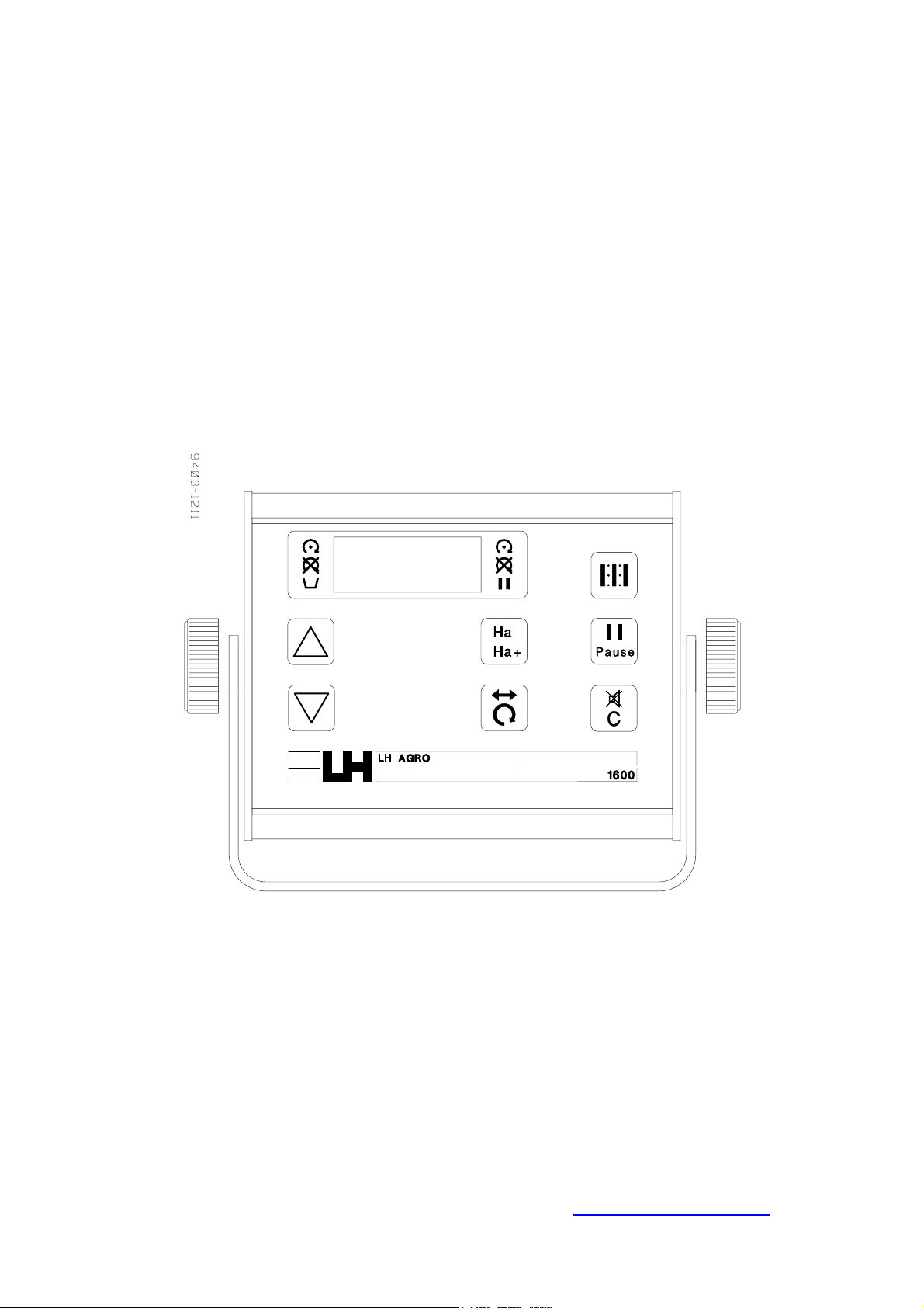
LH 1600 M
LINE TRAM MONITOR
LH No. 010-153-UK
SCA 0500
LH Technologies Denmark ApS
Mølhavevej 2
9440 Aabybro
Denmark
Tel. +45 9696 2500
Fax. +45 9696 2501
Internet: http://www.lh-agro.com/
Page 2
F
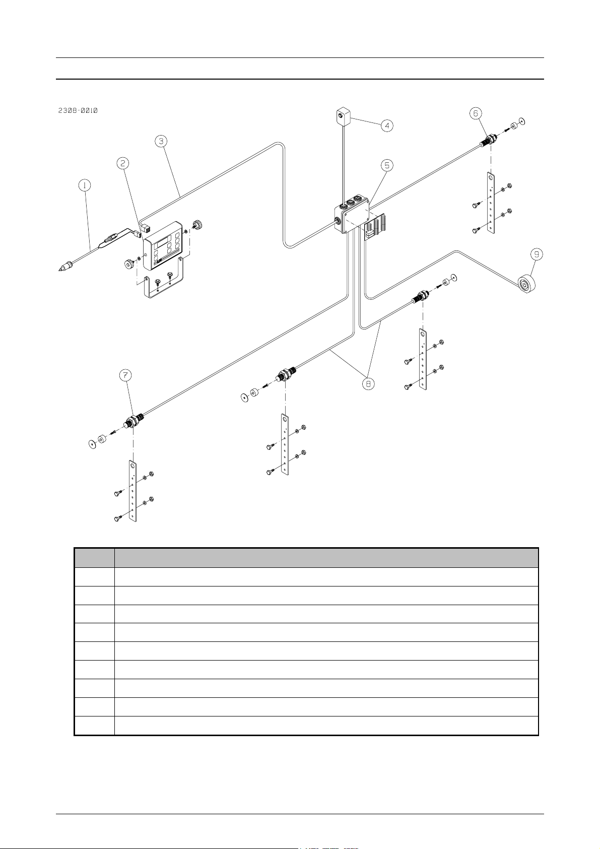
GENERAL OVERVIEW
ITTING INSTRUCTIONS
LH 1600 M
Pos. Description
1 Power cable
2 Monitor
3 Main cable
4 Hopper sensor, empty hopper (optional extra)
5 Junction box
6 Wheel sensor
7 RPM sensor, fan speed (optional extra)
8 Implement sensors
9 RPM sensor, metering shaft (optional extra)
2 LH A
GRO
Page 3
F
ITTING INSTRUCTIONS
LH 1600 M
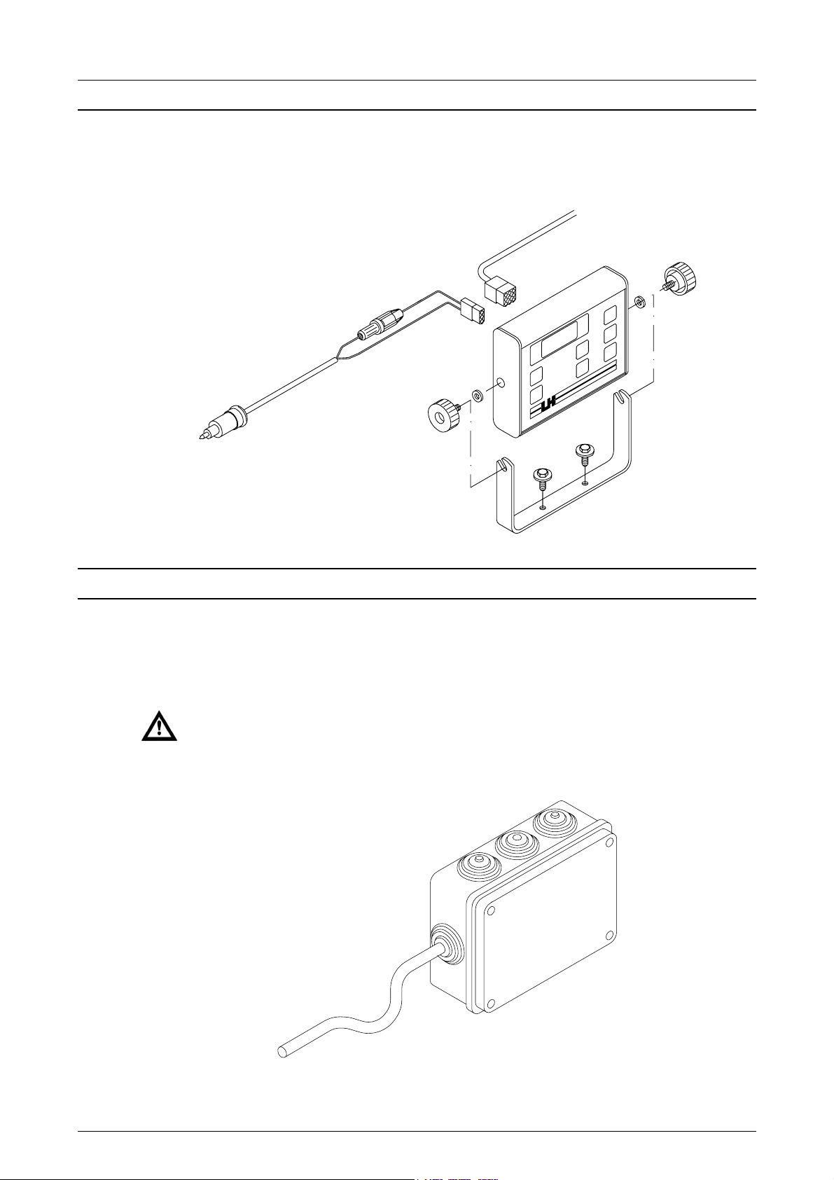
FITTING THE MONITOR
Fit the monitor in the cab in reach of the operator. Connect the monitor to the
tractor’s 12V supply via the 2-pin power plug.
FITTING THE JUNCTION BOX
Fit the junction box on the front of the seed drill in the middle. When the cables
are connected in the box, make sure that each cable has a drip off bend so that
water does not run along the cable and into the junction box.
Make sure that the holes through the rubber grommets are not too large,
make the hole as small as possible and push the cable through.
LH A
GRO
3
Page 4

F
FITTING THE IMPLEMENT SENSORS
The LH 1600M is delivered with 2 implement sensors that are connected via the
junction box print in series. This means that both sensors must be active (magnet
by the sensor) before the bout number is counted and the area counter is
stopped. Fit a sensor on each marker.
ITTING INSTRUCTIONS
LH 1600 M
FITTING THE WHEEL SENSOR
Fit the wheel sensor on the seed drill land wheel. The distance between the
magnet and the sensor is approx. 5-mm.
4 LH A
GRO
Page 5

F
ITTING INSTRUCTIONS
LH 1600 M
FITTING THE RPM SENSOR ON THE FAN
OPTIONAL EXTRA EQUIPMENT (LH NO. 930-983)
A RPM sensor can be fitted on the fan as optional extra equipment. The sensor
can be fitted, i.e. on the end of the fan axle as shown on the following drawing.
The distance between the magnet and the sensor must be 3 – 5 mm.
Remember that the South Pole of the magnet must face the sensor:
FITTING THE HOPPER LEVEL SENSOR (EXTRA EQUIPMENT)
A hopper level sensor can be supplied as optional extra equipment. Fit the hopper
level sensor as shown on the following drawing approx. 150 mm over the bottom
of the hopper. Drill a hole in the correct size for the sensor, which is then screwed
into the plate (do not tighten too hard):
LH A
GRO
5
Page 6
F
ITTING INSTRUCTIONS
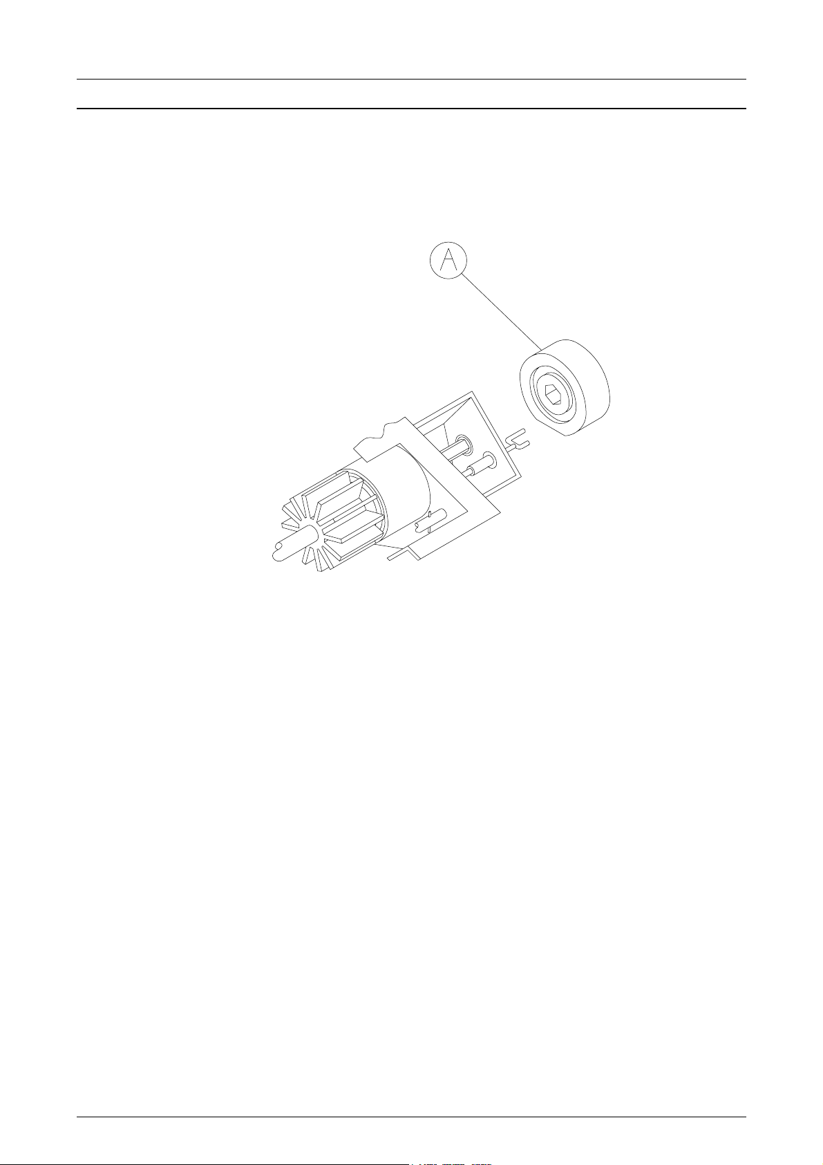
FITTING THE RPM SENSOR FOR THE METERING SHAFT
OPTIONAL EXTRA EQUIPMENT (LH NO. 905-152)
A RPM sensor can be fitted to the metering shaft. The sensor (pos. A) can be
ordered with the above LH no. The sensor is delivered without fitting parts.
LH 1600 M
6 LH A
GRO
Page 7

F
ITTING INSTRUCTIONS
LH 1600 M
ELECTRICAL CONNECTIONS
Connect the sensors and motors in the junction box as on the following diagram.
Stick the supplied label on the inside of the junction box lid:
LH1600M
Pos. Description
1 Main cable to monitor.
2 Empty hopper level sensor (optional extra).
3 RPM sensor for fan speed (optional extra).
4 RPM sensor for metering shaft (optional extra).
5 Speed sensor fitted to the land wheel.
6 Motors that stop and start tramlining.
7 Implement sensor for left marker.
8 Implement sensor for right marker.
Connection to pos. 2 for:
LH nr.: 904-151 LH nr.: 904-152
Connector: Color: Connector: Color:
1 Brown 1 Black
LH A
2 White 2 Red
3 Blue 3 Blue
GRO
7
Page 8

F
NOTES
ITTING INSTRUCTIONS
LH 1600 M
8 LH A
GRO
 Loading...